EP0815876B1 - Instrument sterilization container formed of a liquid crystal polymer - Google Patents
Instrument sterilization container formed of a liquid crystal polymer Download PDFInfo
- Publication number
- EP0815876B1 EP0815876B1 EP97304655A EP97304655A EP0815876B1 EP 0815876 B1 EP0815876 B1 EP 0815876B1 EP 97304655 A EP97304655 A EP 97304655A EP 97304655 A EP97304655 A EP 97304655A EP 0815876 B1 EP0815876 B1 EP 0815876B1
- Authority
- EP
- European Patent Office
- Prior art keywords
- sterilization
- liquid crystal
- tray
- container
- crystal polymer
- Prior art date
- Legal status (The legal status is an assumption and is not a legal conclusion. Google has not performed a legal analysis and makes no representation as to the accuracy of the status listed.)
- Expired - Lifetime
Links
- 0 C*(C**1=CCC=*1)*(C)=C Chemical compound C*(C**1=CCC=*1)*(C)=C 0.000 description 2
Images

Classifications
-
- A—HUMAN NECESSITIES
- A61—MEDICAL OR VETERINARY SCIENCE; HYGIENE
- A61L—METHODS OR APPARATUS FOR STERILISING MATERIALS OR OBJECTS IN GENERAL; DISINFECTION, STERILISATION OR DEODORISATION OF AIR; CHEMICAL ASPECTS OF BANDAGES, DRESSINGS, ABSORBENT PADS OR SURGICAL ARTICLES; MATERIALS FOR BANDAGES, DRESSINGS, ABSORBENT PADS OR SURGICAL ARTICLES
- A61L2/00—Methods or apparatus for disinfecting or sterilising materials or objects other than foodstuffs or contact lenses; Accessories therefor
- A61L2/26—Accessories or devices or components used for biocidal treatment
-
- B—PERFORMING OPERATIONS; TRANSPORTING
- B65—CONVEYING; PACKING; STORING; HANDLING THIN OR FILAMENTARY MATERIAL
- B65D—CONTAINERS FOR STORAGE OR TRANSPORT OF ARTICLES OR MATERIALS, e.g. BAGS, BARRELS, BOTTLES, BOXES, CANS, CARTONS, CRATES, DRUMS, JARS, TANKS, HOPPERS, FORWARDING CONTAINERS; ACCESSORIES, CLOSURES, OR FITTINGS THEREFOR; PACKAGING ELEMENTS; PACKAGES
- B65D1/00—Containers having bodies formed in one piece, e.g. by casting metallic material, by moulding plastics, by blowing vitreous material, by throwing ceramic material, by moulding pulped fibrous material, by deep-drawing operations performed on sheet material
- B65D1/02—Bottles or similar containers with necks or like restricted apertures, designed for pouring contents
- B65D1/0207—Bottles or similar containers with necks or like restricted apertures, designed for pouring contents characterised by material, e.g. composition, physical features
-
- C—CHEMISTRY; METALLURGY
- C08—ORGANIC MACROMOLECULAR COMPOUNDS; THEIR PREPARATION OR CHEMICAL WORKING-UP; COMPOSITIONS BASED THEREON
- C08K—Use of inorganic or non-macromolecular organic substances as compounding ingredients
- C08K3/00—Use of inorganic substances as compounding ingredients
- C08K3/40—Glass
-
- C—CHEMISTRY; METALLURGY
- C08—ORGANIC MACROMOLECULAR COMPOUNDS; THEIR PREPARATION OR CHEMICAL WORKING-UP; COMPOSITIONS BASED THEREON
- C08L—COMPOSITIONS OF MACROMOLECULAR COMPOUNDS
- C08L31/00—Compositions of homopolymers or copolymers of compounds having one or more unsaturated aliphatic radicals, each having only one carbon-to-carbon double bond, and at least one being terminated by an acyloxy radical of a saturated carboxylic acid, of carbonic acid or of a haloformic acid; Compositions of derivatives of such polymers
- C08L31/06—Homopolymers or copolymers of esters of polycarboxylic acids
- C08L31/08—Homopolymers or copolymers of esters of polycarboxylic acids of phthalic acid
-
- A—HUMAN NECESSITIES
- A61—MEDICAL OR VETERINARY SCIENCE; HYGIENE
- A61L—METHODS OR APPARATUS FOR STERILISING MATERIALS OR OBJECTS IN GENERAL; DISINFECTION, STERILISATION OR DEODORISATION OF AIR; CHEMICAL ASPECTS OF BANDAGES, DRESSINGS, ABSORBENT PADS OR SURGICAL ARTICLES; MATERIALS FOR BANDAGES, DRESSINGS, ABSORBENT PADS OR SURGICAL ARTICLES
- A61L2/00—Methods or apparatus for disinfecting or sterilising materials or objects other than foodstuffs or contact lenses; Accessories therefor
- A61L2/02—Methods or apparatus for disinfecting or sterilising materials or objects other than foodstuffs or contact lenses; Accessories therefor using physical phenomena
- A61L2/04—Heat
- A61L2/06—Hot gas
- A61L2/07—Steam
-
- A—HUMAN NECESSITIES
- A61—MEDICAL OR VETERINARY SCIENCE; HYGIENE
- A61L—METHODS OR APPARATUS FOR STERILISING MATERIALS OR OBJECTS IN GENERAL; DISINFECTION, STERILISATION OR DEODORISATION OF AIR; CHEMICAL ASPECTS OF BANDAGES, DRESSINGS, ABSORBENT PADS OR SURGICAL ARTICLES; MATERIALS FOR BANDAGES, DRESSINGS, ABSORBENT PADS OR SURGICAL ARTICLES
- A61L2/00—Methods or apparatus for disinfecting or sterilising materials or objects other than foodstuffs or contact lenses; Accessories therefor
- A61L2/02—Methods or apparatus for disinfecting or sterilising materials or objects other than foodstuffs or contact lenses; Accessories therefor using physical phenomena
- A61L2/14—Plasma, i.e. ionised gases
-
- A—HUMAN NECESSITIES
- A61—MEDICAL OR VETERINARY SCIENCE; HYGIENE
- A61L—METHODS OR APPARATUS FOR STERILISING MATERIALS OR OBJECTS IN GENERAL; DISINFECTION, STERILISATION OR DEODORISATION OF AIR; CHEMICAL ASPECTS OF BANDAGES, DRESSINGS, ABSORBENT PADS OR SURGICAL ARTICLES; MATERIALS FOR BANDAGES, DRESSINGS, ABSORBENT PADS OR SURGICAL ARTICLES
- A61L2/00—Methods or apparatus for disinfecting or sterilising materials or objects other than foodstuffs or contact lenses; Accessories therefor
- A61L2/16—Methods or apparatus for disinfecting or sterilising materials or objects other than foodstuffs or contact lenses; Accessories therefor using chemical substances
- A61L2/20—Gaseous substances, e.g. vapours
- A61L2/206—Ethylene oxide
-
- A—HUMAN NECESSITIES
- A61—MEDICAL OR VETERINARY SCIENCE; HYGIENE
- A61L—METHODS OR APPARATUS FOR STERILISING MATERIALS OR OBJECTS IN GENERAL; DISINFECTION, STERILISATION OR DEODORISATION OF AIR; CHEMICAL ASPECTS OF BANDAGES, DRESSINGS, ABSORBENT PADS OR SURGICAL ARTICLES; MATERIALS FOR BANDAGES, DRESSINGS, ABSORBENT PADS OR SURGICAL ARTICLES
- A61L2/00—Methods or apparatus for disinfecting or sterilising materials or objects other than foodstuffs or contact lenses; Accessories therefor
- A61L2/16—Methods or apparatus for disinfecting or sterilising materials or objects other than foodstuffs or contact lenses; Accessories therefor using chemical substances
- A61L2/20—Gaseous substances, e.g. vapours
- A61L2/208—Hydrogen peroxide
-
- A—HUMAN NECESSITIES
- A61—MEDICAL OR VETERINARY SCIENCE; HYGIENE
- A61L—METHODS OR APPARATUS FOR STERILISING MATERIALS OR OBJECTS IN GENERAL; DISINFECTION, STERILISATION OR DEODORISATION OF AIR; CHEMICAL ASPECTS OF BANDAGES, DRESSINGS, ABSORBENT PADS OR SURGICAL ARTICLES; MATERIALS FOR BANDAGES, DRESSINGS, ABSORBENT PADS OR SURGICAL ARTICLES
- A61L2202/00—Aspects relating to methods or apparatus for disinfecting or sterilising materials or objects
- A61L2202/10—Apparatus features
- A61L2202/12—Apparatus for isolating biocidal substances from the environment
- A61L2202/122—Chambers for sterilisation
-
- A—HUMAN NECESSITIES
- A61—MEDICAL OR VETERINARY SCIENCE; HYGIENE
- A61L—METHODS OR APPARATUS FOR STERILISING MATERIALS OR OBJECTS IN GENERAL; DISINFECTION, STERILISATION OR DEODORISATION OF AIR; CHEMICAL ASPECTS OF BANDAGES, DRESSINGS, ABSORBENT PADS OR SURGICAL ARTICLES; MATERIALS FOR BANDAGES, DRESSINGS, ABSORBENT PADS OR SURGICAL ARTICLES
- A61L2202/00—Aspects relating to methods or apparatus for disinfecting or sterilising materials or objects
- A61L2202/10—Apparatus features
- A61L2202/18—Aseptic storing means
- A61L2202/182—Rigid packaging means
-
- A—HUMAN NECESSITIES
- A61—MEDICAL OR VETERINARY SCIENCE; HYGIENE
- A61L—METHODS OR APPARATUS FOR STERILISING MATERIALS OR OBJECTS IN GENERAL; DISINFECTION, STERILISATION OR DEODORISATION OF AIR; CHEMICAL ASPECTS OF BANDAGES, DRESSINGS, ABSORBENT PADS OR SURGICAL ARTICLES; MATERIALS FOR BANDAGES, DRESSINGS, ABSORBENT PADS OR SURGICAL ARTICLES
- A61L2202/00—Aspects relating to methods or apparatus for disinfecting or sterilising materials or objects
- A61L2202/20—Targets to be treated
- A61L2202/24—Medical instruments, e.g. endoscopes, catheters, sharps
Definitions
- This invention relates to a sterilization container for use in sterilizing, storing and transporting and presenting instruments, in particular medical instruments.
- reusable medical instruments require sterilization before each use.
- Many methods are employed for sterilization, but the most prevalent methods include: steam autoclaving, vapor phase chemical sterilization and vapor phase chemical sterilization in combination with a plasma field.
- the chemical sterilants include hydrogen peroxide and ethylene oxide.
- One of the most versatile, quickest and most effective methods employs an initial period of vapor phase hydrogen peroxide followed by application of an electromagnetic field which drives the hydrogen peroxide vapor into the plasma state of matter.
- the plasma phase enhances the sterilization and when the electromagnetic field is released the plasma free radicals recombine to form water and oxygen.
- instruments are placed into a container and then the container is placed into the sterilization device.
- Portals for the passage of sterilizing media must be provided.
- the container is usually provided with a filter material which allows passage of the sterilizing media through the portals and container yet prevents the ingress of microorganisms.
- the portal and filter material may be combined as in the Nichols, US-A-4,704,254, issued November 3, 1987, or the container may be provided with a plurality of apertures and then be wrapped prior to each sterilization in a filter wrapping material such as SPUNGUARD brand CSR wrap available from Kimberly Clark Corporation which is a spunbonded/meltblown/spunbonded (SMS) laminate consisting of nonwoven outer layers of spun-bonded polyolefins and an interior barrier layer of melt-blown polyolefins.
- SMS spunbonded/meltblown/spunbonded
- holding devices of one form or another hold one or more individual instruments within the container.
- the holding device may comprise clips or other such arrangements, which may or may not be specially adapted to hold a particular medical instrument.
- One popular holding device simply comprises a plurality of upwardly extending flexible projections, sometimes called fingers, which prevent the instruments from moving about within the container and provide minimal contact with the instruments. Typically, these are provided on a mat which lies in the bottom of the container.
- the ideal sterilization tray or container is compatible with all major sterilization methodologies, minimizes or eliminates condensation collection through thin, yet strong, walls, has a long life, is easy to operate and can be provided for a reasonable cost.
- Containers presently known suffer from shortcomings which limit their performance in one or more of these areas. For instance, many trays designed for steam autoclaves are formed of stainless steel which may interfere with formation of a plasma in some systems. Other trays made of polymers may not have sufficient heat resistance to withstand repeated steam sterilization cycles. Some tray materials interact with chemical sterilants, and may even decompose the sterilant. Other materials may absorb excessive amounts of chemical sterilants, thereby decreasing the sterilization effectiveness by decreasing the amount of sterilant available for sterilizing.
- the present invention overcomes these and other limitations in the prior art and provides compatibility with hydrogen peroxide vapor, liquid or gas plasma, steam autoclaves, ethylene oxide and other chemical or heat based sterilizing methods. It is durable, inexpensive to produce, enhances drainage and limits condensate entrapment.
- a sterilization container for sterilizing instruments comprises a wall enclosing the container, means for holding a medical instrument within the container; and one or more openings into the container for admitting sterilizing gases.
- the wall is formed of a thermoplastic liquid crystal polymer whereby the wall resists chemical attack from hydrogen peroxide, ethylene oxide, and other chemical sterilants or their precursors, the wall does not unduly interfere with any electromagnetic fields, and the wall resists attack from elevated temperatures.
- the thermoplastic liquid crystal polymer comprises a wholly aromatic polyester.
- the liquid crystal polymer is preferably selected from the group consisting of: polybenzoate-naphthalate; polybenzoate-terephthalate bisphenol-isophthalate; polybenzoate-terephthalate-ethylene glycol; and polynaphthalate-amino terephthalate.
- the liquid crystal polymer can be reinforced with a filler, such as glass, mineral fibers, or fluoropolymers, in the form of powder, flakes or fibers.
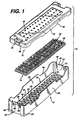
- FIG. 1 illustrates a first embodiment of a sterilization container 10 according to the present invention.
- the container 10 comprises a tray 12, a mat 14, and a lid 16.
- the tray 12 comprises a rectangular base 18 from which extends upwardly two opposing side walls 20 and two opposing end walls 22. Corners 24 formed between the side walls 20 and end walls 22 are rounded for a pleasing appearance, improved strength, and to reduce sharp edges which may compromise the integrity of an operator's protective rubber glove (not shown).
- a fillet 26 between the base 18 and the side and end walls 20 and 22 also enhances the strength of the tray 12.
- the base 18 comprises a plurality of drainage wells 28, each one comprising a downwardly sloping surface 30 terminating in a drainage aperture 32.
- the sloping surfaces 30 of adjacent drainage wells 28 intersect to form peaks 34.
- the peaks 34 form distinct lines or singularities, as opposed to rounded interfaces between adjacent sloping surfaces 30. This minimizes the surface areas of the peaks 34 which support the mat 14, thereby reducing the area of contact between the base 18 and mat 14. Thus, little space is provided in which condensate or other liquid matter may become trapped.
- the mat 14 has a plurality of mat apertures 38 therethrough and a plurality of upwardly extending projections 36 for holding medical instruments (not shown) that are to be sterilized within the container 10. Apertures 38 on the mat 14 align with drainage apertures 32 through the tray base 18.
- the mat 14 is formed of a silicone or other elastomeric substance which resists high heat associated with steam autoclaving, and also resists chemical attack from hydrogen peroxide, ethylene oxide, or other chemical or their precursors, particularly the oxidizing type sterilants. Further, the material of the mat 14 should not absorb or chemically interact with such chemical sterilants.
- the upwardly extending projections 36 may take several forms. For instance, they may taper upwardly, or have constant diameter.
- the tip may be flat, rounded or radiused. They may be relatively soft or they may be rigid.
- the total number and spacing of the projections 36 may also be varied. Such mats are known in the art, and it is well within the ordinary skill of a practitioner in the art to vary these design parameters to achieve a desired overall effect.
- the container lid 16 has a plurality of lid apertures 40 to promote the passage of sterilizing vapors therethrough.
- the lid apertures 40 may align with the drainage apertures in the tray 12, but need not be so aligned.
- the lid 16 further comprises downwardly depending sidewalls 42 and endwalls 44.
- the tray 12 and lid 16 are sized so that the tray endwalls or sidewalls and endwalls 20 and 22 fit snugly within the lid sidewalls and endwalls 42 and 44.
- a latching mechanism 46 is integrally formed in the tray 12 and lid 16.
- Each of the base endwalls 22 has a recessed portion 48.
- a pair of U-shaped cutouts 50 in each recess portion 48 define a flexible tang 52.
- An upper extent 54 of each tang 52 comprises a sloped camming surface 56 and a retaining lip 58.
- Recessed portions 60 in the lid 16 align with the endwall recesses 48 and comprise an aperture 62 and retaining lip 64.
- each tang 52 is inserted into the corresponding aperture 62 in the lid 16 and cammed over the retaining lip 64 until the retaining lip 58 on the tang 52 snaps into engagement with the retaining lip 64.
- Inward pressure on the tang 52 applied manually, disengages the retaining lips 58 and 64 to release the latch mechanism 46.
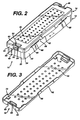
- each of the tray sidewalls 20 and lid sidewalls 42 contain several shallow cutout portions 66. As best seen in FIG. 2, when the lid 16 and tray 12 are interconnected, the cutout portions 66 thereon align with each other to form shallow slit-like openings 68 into the container 10. This enhances the flow of sterilizing gases through the container 10.
- four pads 70 are provided inside of the lid 16 to space the lid 16 from the tray 12 and thereby minimize any surface contact area therebetween which might block the flow of gas or liquid or which might trap, condensate, or other liquid material.
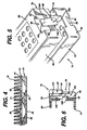
- FIG. 4 illustrates the drainage enhancing features of the present invention.
- the peaks 34 of the base 18 support the flexible mat 14. Condensate or other liquid which enters between the mat 14 and base 18 comes within one of the drainage wells 28.
- the small contact surface 71 formed between the peaks 34 and mat 14 prevents condensate or other liquids from being trapped between surfaces of the base 18 and mat 14.
- the downwardly sloping surfaces 30 of the drainage wells 28 encourage any condensate or other liquids to move toward the drainage apertures 32. Condensate then physically drains out of the container 10.
- the supporting characteristics of the peaks 34 can not be over emphasized. Silicone and other elastomeric materials suitable for forming the mat 14 tend to soften considerably in high temperature sterilizing environments. Accordingly, it is crucial to properly support the mat 14.
- tray material for use in hydrogen peroxide or chemical based sterilization technology is influenced by the chemical resistance and inertness of the material with respect to the sterilant or precursor for chemical plasma.
- the inertness of the material with respect to the plasma precursor is even more critical due to possible low concentrations of precursor available to generate plasma in some preferred plasma methodologies.
- the tray material should be nonreactive to the sterilant(s), or the precursor(s) for the chemical plasma in order not to affect biological lethality of the sterilizer chamber.
- the material should also be resistant to the chemical and thermal environments during the cleaning and decontamination procedure of instruments and trays as commonly used in clinical situations. Hospitals typically use a washer/decontaminator operating at 132°C (270°F) as well as detergents and enzymatic cleaners for removing organic matter.
- the ideal tray material should further be compatible with all major sterilization methods employed by hospitals and the like, including steam (flash and gravity), ethylene oxide gas, and hydrogen peroxide based sterilizers.
- steam flash and gravity
- ethylene oxide gas ethylene oxide gas
- hydrogen peroxide based sterilizers One example of the hydrogen peroxide based plasma sterilization is the STERRAD Sterilization System that uses hydrogen peroxide plasma to eliminate microorganisms on medical instruments. Therefore, the ideal material should have adequate thermo-mechanical properties to withstand steam, exhibit low ethylene oxide residuals after processing, and have extremely low interaction with H 2 O 2 or other oxidative sterilants.
- the most preferred structures are the wholly polyester aromatic liquid crystal polymers, which are polybenzoate-naphthalate and polybenzoate-terephthalate-bis phenol-isophthalate. Both neat and reinforced grades are preferred due to the structural strength of this material family.
- the most preferred reinforcements fillers are glass or mineral fibers, or fluoropolymers in powders,
- the first characteristic to be controlled is the surface smoothness of final product.
- the surface of the sterilization tray should be as smooth as possible so as to reduce surface area/volume ratio. Since both chemical and physical interactions with sterilants or precursor(s) for chemical plasma and material degradation are a function of the surface area/volume ratio, smooth surfaces will reduce the rate of these interactions.
- the second characteristic to be controlled is wall thickness.
- Wall thickness is integral to the structural strength of the tray or container.
- the condensation of chemical sterilant or precursor for chemical plasma should be minimized.
- Condensation is a function of the thermal mass and heat transfer characteristics of the tray or container, which may reduce the amount of available sterilant or precursor for chemical plasma in vapor phase and thereby effect the biological lethality.
- the wall thickness of the tray or container should be minimized.
- the preferred materials for forming the tray 12 and lid 16 are as follows:
- FIGS. 5 and 6 illustrate a second embodiment of a sterilization container according to the invention.
- the container 72 comprises a tray 74, lid 76 and mat (not shown) similar to the previous embodiment. However, it incorporate an alternative latching mechanism 78.
- the lid 76 comprises an apertured top wall 80; side and endwalls 82 and 84, respectively, depending therefrom.
- a latch member 86 is integrally molded into a recessed portion 88 in each endwall 84 of the lid 76.
- a pair of torsion bars 90 extend inwardly of the recess portion 88 from opposing sidewalls 92 thereof to rotatably support the latch member 86. The torsion bars 90 bias the latch member 86 into a standing, engaged position as shown best in FIG. 6, and allow a limited amount of rotation away from the engaged position.
- a notch 94 in each endwall 96 of the tray 74 forms an engagement surface 98.
- the torsion bars 90 return the latch member 86 to its standing, engaged position.
- All edges and surfaces of the latch member 86 are rounded and smooth especially those on that portion 108 of the latch member facing outwardly of the recess 88. The only exception is the lip 100 which lies on that portion 109 of the latch member facing inwardly of the tray 74, to thereby present no sharp edges or surfaces which may engage and tear the users protective glove (not shown). All portions of the latching mechanism 78 are integrally molded with either the tray 74 or lid 76 thereby reducing manufacturing and assembly costs.
- the orientation of the latching mechanism 78 may be reversed, such that the latch member 86 is formed in the tray 74.
- the lid 76 could be adapted to pivot about a hinge (not shown) and of course, the latching mechanism 78 need not be provided in the endwall 84 but could be located elsewhere on the container 72. However, the orientation illustrated in FIG. 5 is particularly convenient.
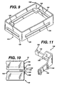
- FIGS. 7 and 8 illustrate an alternative arrangement for a tray 110 according to the invention.
- the tray 110 may be used with a sterilization container as in the first and second embodiment and differs primarily in its base 112.
- the base 112 comprises a flat panel 114 having a plurality of apertures 116 therethrough. Additionally, a number of larger, elongated apertures 118 penetrate the panel 114 and an upwardly extending lip 120 encircles each of the elongated apertures 118.
- the lips 120 support a mat 122 and further provide rigidity to the tray base 112. Apertures 124 through the mat 122 aligned with the elongated apertures 118 through the tray base 112 to provide an efficient diffusion path for sterilizing gases.
- FIG. 9 illustrates a stacking device 124 for stacking sterilization trays 10 during a sterilization procedure.
- the stacking device 124 is rectangular in shape and of slightly larger dimensions and than the sterilization tray 10 (not shown in FIG. 9). It comprises vertical sidewalls 126 and vertical endwalls 128.
- An L-shaped shelf member 130 extends horizontally inwardly from each comer 132 of the stacking device 124.
- each of the sidewalls 126 and endwalls 128 has elongated openings 134 therethrough of similar vertical dimensions to the shelf member 130 so that when containers 10 are stacked using the stacking device 124, the flow of sterilizing gases into and out of the individual containers 10 is not impeded by the stacking device 124.
- FIG. 10 shows two sterilization containers 10, each wrapped in a sterile wrap material 136.
- the stacking member 124 sits atop a first tray 10 with the shelf member 130 resting upon the tray 10.
- the second tray 10 rests upon the shelf member 130.
- Both trays 10 are positioned within the side and endwalls 126 and 128 of the stacking device. Thus, the two trays 10 are stacked and separated from each other with a full and open flow path thereabout.
- FIG. 11 illustrates an alternative embodiment of a stacking device 138.
- each of the side and endwalls 140 and 142 respectively have a low vertical profile vertically offset from a shelf member 144 to thereby provide an open flow path to the stacked trays (not shown in FIG. 11).
- Vertical ribs 146 on the side and endwalls 140 and 142 provide rigidity and maintain an open flow path, if the stacking device is placed next to another stacking device or flat surface.
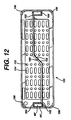
- FIG. 12 illustrates an alternative embodiment of a lid 150 according to the invention.
- the lid 150 duplicates the lid 16 of FIGS. 1 and 3, with several modifications. Accordingly, features similar to those on the lid 16 will be designated with similar numerals with the addition of a single prime symbol ('). Specifically, the lid 150 differs from the lid 16 in its mixture of round and elongated apertures 152 and 154 respectively. Also, an additional fillet 156 has been added at each comer which both strengthens the lid 150 aids in lifting the lid 150 above the base 8 (not shown in FIG. 12) for improved circulation.
- Liquid crystal polymers are known for their difficulty in molding.
- One particular problem arises where opposing flows of molten polymer meet. Such areas often have reduced strength and accordingly it is desirable to locate them away from areas of the molded article which will be subjected to high levels of stress.
- the recess 60' is formed by a core pin in the mold (not shown). The molten polymer flows around the core pin and meets to enclose the recess 60'. Normally these flows would meet at the retaining lip 64'. However, this area is subjected to high stresses.
- the lid 150 is formed with a pair of flow leaders 158, each leading from a center area 160 of the lid 150 where the molten polymer is injected in the molding process and leading to an inside corner 162 of the respective recesses 60'. During the molding process the molten polymer thus flows around the core pin and the opposing flows meet at a side portion 164 of the recess 60'.
Abstract
Description
- This invention relates to a sterilization container for use in sterilizing, storing and transporting and presenting instruments, in particular medical instruments.
- Most, reusable medical instruments require sterilization before each use. Many methods are employed for sterilization, but the most prevalent methods include: steam autoclaving, vapor phase chemical sterilization and vapor phase chemical sterilization in combination with a plasma field. The chemical sterilants include hydrogen peroxide and ethylene oxide. One of the most versatile, quickest and most effective methods employs an initial period of vapor phase hydrogen peroxide followed by application of an electromagnetic field which drives the hydrogen peroxide vapor into the plasma state of matter. The plasma phase enhances the sterilization and when the electromagnetic field is released the plasma free radicals recombine to form water and oxygen.
- Typically, instruments are placed into a container and then the container is placed into the sterilization device. Portals for the passage of sterilizing media must be provided. Also, the container is usually provided with a filter material which allows passage of the sterilizing media through the portals and container yet prevents the ingress of microorganisms. The portal and filter material may be combined as in the Nichols, US-A-4,704,254, issued November 3, 1987, or the container may be provided with a plurality of apertures and then be wrapped prior to each sterilization in a filter wrapping material such as SPUNGUARD brand CSR wrap available from Kimberly Clark Corporation which is a spunbonded/meltblown/spunbonded (SMS) laminate consisting of nonwoven outer layers of spun-bonded polyolefins and an interior barrier layer of melt-blown polyolefins.
- Usually, holding devices of one form or another hold one or more individual instruments within the container. The holding device may comprise clips or other such arrangements, which may or may not be specially adapted to hold a particular medical instrument. One popular holding device simply comprises a plurality of upwardly extending flexible projections, sometimes called fingers, which prevent the instruments from moving about within the container and provide minimal contact with the instruments. Typically, these are provided on a mat which lies in the bottom of the container.
- The ideal sterilization tray or container is compatible with all major sterilization methodologies, minimizes or eliminates condensation collection through thin, yet strong, walls, has a long life, is easy to operate and can be provided for a reasonable cost. Containers presently known suffer from shortcomings which limit their performance in one or more of these areas. For instance, many trays designed for steam autoclaves are formed of stainless steel which may interfere with formation of a plasma in some systems. Other trays made of polymers may not have sufficient heat resistance to withstand repeated steam sterilization cycles. Some tray materials interact with chemical sterilants, and may even decompose the sterilant. Other materials may absorb excessive amounts of chemical sterilants, thereby decreasing the sterilization effectiveness by decreasing the amount of sterilant available for sterilizing.
- The present invention overcomes these and other limitations in the prior art and provides compatibility with hydrogen peroxide vapor, liquid or gas plasma, steam autoclaves, ethylene oxide and other chemical or heat based sterilizing methods. It is durable, inexpensive to produce, enhances drainage and limits condensate entrapment.
- A sterilization container for sterilizing instruments according to the present invention, comprises a wall enclosing the container, means for holding a medical instrument within the container; and one or more openings into the container for admitting sterilizing gases. The wall is formed of a thermoplastic liquid crystal polymer whereby the wall resists chemical attack from hydrogen peroxide, ethylene oxide, and other chemical sterilants or their precursors, the wall does not unduly interfere with any electromagnetic fields, and the wall resists attack from elevated temperatures.
- Preferably, the thermoplastic liquid crystal polymer comprises a wholly aromatic polyester. The liquid crystal polymer is preferably selected from the group consisting of: polybenzoate-naphthalate; polybenzoate-terephthalate bisphenol-isophthalate; polybenzoate-terephthalate-ethylene glycol; and polynaphthalate-amino terephthalate. The liquid crystal polymer can be reinforced with a filler, such as glass, mineral fibers, or fluoropolymers, in the form of powder, flakes or fibers.
-
- FIG. 1 is an exploded, perspective view of a sterilization container according to the invention;
- FIG. 2 is a perspective view of the assembled sterilization container of FIG. 1;
- FIG. 3 is a perspective view of the inverted lid of the sterilization container of FIG. 1;
- FIG. 4 is a cross-section taken along lines 4 - 4 of FIG. 2;
- FIG. 5 is a perspective, disassembly view of a portion of a sterilization container according to the present invention which illustrates an alternative latching mechanism according to the present invention;
- FIG. 6 is a cross-section of the latching mechanism of FIG. 5, with the latch shown in the closed position;
- FIG. 7 is a perspective view of a further embodiment of a sterilization tray according to the present, invention;
- FIG. 8 is a cross-section taken along line 8 -- 8 of FIG. 7;
- FIG. 9 is a perspective view of a stacking device according to the present invention;
- FIG. 10 is a side view of the stacking device of FIG. 9 positioned between two sterilization containers to stack and separate the containers;
- FIG. 11 is a perspective view of a further embodiment of a stacking device according to the present invention; and
- FIG. 12 is underside plan view of a further embodiment of a lid according to the present invention.
-
- FIG. 1 illustrates a first embodiment of a
sterilization container 10 according to the present invention. Thecontainer 10 comprises atray 12, amat 14, and alid 16. Thetray 12 comprises arectangular base 18 from which extends upwardly twoopposing side walls 20 and twoopposing end walls 22.Corners 24 formed between theside walls 20 andend walls 22 are rounded for a pleasing appearance, improved strength, and to reduce sharp edges which may compromise the integrity of an operator's protective rubber glove (not shown). Afillet 26 between thebase 18 and the side andend walls tray 12. - The
base 18 comprises a plurality ofdrainage wells 28, each one comprising a downwardly slopingsurface 30 terminating in adrainage aperture 32. The slopingsurfaces 30 ofadjacent drainage wells 28 intersect to formpeaks 34. Preferably, thepeaks 34 form distinct lines or singularities, as opposed to rounded interfaces betweenadjacent sloping surfaces 30. This minimizes the surface areas of thepeaks 34 which support themat 14, thereby reducing the area of contact between thebase 18 andmat 14. Thus, little space is provided in which condensate or other liquid matter may become trapped. - The
mat 14 has a plurality ofmat apertures 38 therethrough and a plurality of upwardly extendingprojections 36 for holding medical instruments (not shown) that are to be sterilized within thecontainer 10.Apertures 38 on themat 14 align withdrainage apertures 32 through thetray base 18. Preferably, themat 14 is formed of a silicone or other elastomeric substance which resists high heat associated with steam autoclaving, and also resists chemical attack from hydrogen peroxide, ethylene oxide, or other chemical or their precursors, particularly the oxidizing type sterilants. Further, the material of themat 14 should not absorb or chemically interact with such chemical sterilants. - The upwardly extending
projections 36 may take several forms. For instance, they may taper upwardly, or have constant diameter. The tip may be flat, rounded or radiused. They may be relatively soft or they may be rigid. The total number and spacing of theprojections 36 may also be varied. Such mats are known in the art, and it is well within the ordinary skill of a practitioner in the art to vary these design parameters to achieve a desired overall effect. - The
container lid 16 has a plurality oflid apertures 40 to promote the passage of sterilizing vapors therethrough. The lid apertures 40 may align with the drainage apertures in thetray 12, but need not be so aligned. Thelid 16 further comprises downwardly depending sidewalls 42 andendwalls 44. - Turning also now to FIG. 2, the
tray 12 andlid 16 are sized so that the tray endwalls or sidewalls and endwalls 20 and 22 fit snugly within the lid sidewalls and endwalls 42 and 44. Preferably, alatching mechanism 46 is integrally formed in thetray 12 andlid 16. Each of the base endwalls 22 has a recessedportion 48. A pair ofU-shaped cutouts 50 in eachrecess portion 48 define aflexible tang 52. Anupper extent 54 of eachtang 52 comprises a slopedcamming surface 56 and a retaininglip 58. Recessedportions 60 in thelid 16 align with the endwall recesses 48 and comprise anaperture 62 and retaininglip 64. To engage thelatch mechanism 46, thecamming surface 56 on eachtang 52 is inserted into the correspondingaperture 62 in thelid 16 and cammed over the retaininglip 64 until the retaininglip 58 on thetang 52 snaps into engagement with the retaininglip 64. Inward pressure on thetang 52, applied manually, disengages the retaininglips latch mechanism 46. - To enhance the flow of sterilizing gases through the
container 10, each of the tray sidewalls 20 and lid sidewalls 42 contain severalshallow cutout portions 66. As best seen in FIG. 2, when thelid 16 andtray 12 are interconnected, thecutout portions 66 thereon align with each other to form shallow slit-like openings 68 into thecontainer 10. This enhances the flow of sterilizing gases through thecontainer 10. - Turning to FIG. 3, four
pads 70 are provided inside of thelid 16 to space thelid 16 from thetray 12 and thereby minimize any surface contact area therebetween which might block the flow of gas or liquid or which might trap, condensate, or other liquid material. - FIG. 4 illustrates the drainage enhancing features of the present invention. The
peaks 34 of the base 18 support theflexible mat 14. Condensate or other liquid which enters between themat 14 andbase 18 comes within one of thedrainage wells 28. Thesmall contact surface 71 formed between thepeaks 34 andmat 14 prevents condensate or other liquids from being trapped between surfaces of thebase 18 andmat 14. The downwardly slopingsurfaces 30 of thedrainage wells 28 encourage any condensate or other liquids to move toward thedrainage apertures 32. Condensate then physically drains out of thecontainer 10. The supporting characteristics of thepeaks 34 can not be over emphasized. Silicone and other elastomeric materials suitable for forming themat 14 tend to soften considerably in high temperature sterilizing environments. Accordingly, it is crucial to properly support themat 14. - The selection of tray material for use in hydrogen peroxide or chemical based sterilization technology is influenced by the chemical resistance and inertness of the material with respect to the sterilant or precursor for chemical plasma. For chemical plasma sterilization methods which depend on excited free radicals, the inertness of the material with respect to the plasma precursor is even more critical due to possible low concentrations of precursor available to generate plasma in some preferred plasma methodologies. The tray material should be nonreactive to the sterilant(s), or the precursor(s) for the chemical plasma in order not to affect biological lethality of the sterilizer chamber. For ease of operation, the material should also be resistant to the chemical and thermal environments during the cleaning and decontamination procedure of instruments and trays as commonly used in clinical situations. Hospitals typically use a washer/decontaminator operating at 132°C (270°F) as well as detergents and enzymatic cleaners for removing organic matter.
- The ideal tray material should further be compatible with all major sterilization methods employed by hospitals and the like, including steam (flash and gravity), ethylene oxide gas, and hydrogen peroxide based sterilizers. One example of the hydrogen peroxide based plasma sterilization is the STERRAD Sterilization System that uses hydrogen peroxide plasma to eliminate microorganisms on medical instruments. Therefore, the ideal material should have adequate thermo-mechanical properties to withstand steam, exhibit low ethylene oxide residuals after processing, and have extremely low interaction with H2O2 or other oxidative sterilants.
- We have rigorously examined and tested many materials to identify a material suitable for such varied and extreme service environments. As a result of our investigations, we have found that neat (non-reinforced) and reinforced polyester based liquid crystal polymers, neat and reinforced polyesters, and reinforced polypropylene. Within the scope of the present invention, the most preferred material is neat or reinforced polyester liquid crystal polymer. One commercially available example of a suitable liquid crystal polymer is the Vectra® family produced by the Hoechst Celanese Corporation.
- There are preferred chemical structures of liquid crystal polymers, either with or without reinforcement, which can be considered as tray materials:
- Liquid crystal polymers, in which there are four major structural
variations:
- 1. Polybenzoate-naphthlate
An example of a commercially available product is under the tradename VECTRA® A and C series by Hoechst Celanese Corporation.

- 2. Polybenzoate-terephthalate-bis phenol-isophthalate
An example of a commercially available product is under the tradename of Xydar® by Amoco Performance Products.

- 3. Polybenzonate-terephthalate-ethylene glycol
An example of a commercially available product is under the tradename of X7G and X7H by Eastman Chemical Company and

- 4. Polynaphthalate-amino terephthalate
An example of a commercially available product is under the tradename of Vectra® B series by Hoechst Celanese Corporation.

-
- The most preferred structures are the wholly polyester aromatic liquid crystal polymers, which are polybenzoate-naphthalate and polybenzoate-terephthalate-bis phenol-isophthalate. Both neat and reinforced grades are preferred due to the structural strength of this material family. The most preferred reinforcements fillers are glass or mineral fibers, or fluoropolymers in powders,
- The material characteristics in a hydrogen peroxide environment are of particular importance. Both the tendency to absorb hydrogen peroxide and the tendency to decompose hydrogen peroxide were studied for a variety of materials. The following Table 1 illustrates the results for some of the more important materials.
Material Tradename Material Family H2O2 Absorption (ppm) H2O2 Decomposition (g/g) Ultem 1000 Polyetherimide 144.3 Ultem CRS 5011 Polyetherimide 346 Radel R-5100 Polyaryl sulfone 356 Noryl Polyphenylene oxide/ Polystyrene blend 52 Vectra A530 Polyester liquid crystal polymer (mineral fiber filled) 4.5 0.009 Vectra A115 Polyester liquid crystal polymer (glass fiber filled) no absorption 0.013 DPP40W18357 40% calcium carbonate filled polypropylene no absorption 0.012 Ektar EG-015 Glass fiber filled poly ethylene terephthalate 3.3 no decomposition - Another study was conducted to evaluate the compatibility of tray materials with simulated hydrogen peroxide plasma sterilization and washer/decontamination cycles, which includes alternating hydrogen peroxide plasma sterilization cycle, washer/decontaminator cycle and enzymatic cleaner immersion. The samples were placed under 0.5% and 0.75% strain. The following Table 2 illustrates the results of this evaluation.
Material Strain Level Yield Strength [MPa] Tensile Strength [MPa] Elongation at Break Ultem 1000 Control 106
(15,320 psi)101
(14,690 psi)68.5% Ultem 1000 0.5% 70
(10,140 psi)70
(10,140 psi)2.4% Ultem 1000 0.75% 80
(11,630 psi)77
(11,230 psi)4.2% Noryl Control 69
(9,965 psi)54
(7,852 psi)13.1% Noryl 0.5% 72
(10,400 psi)55
(7,961 psi)9.3% Noryl 0.75% 73
(10,550 psi)56
(8,091 psi)98.5% Vectra A530 Control n/a 156
(22,672 psi)n/a Vectra A530 0.5% n/a 154
(22,371 psi)n/a Vectra A530 0.75% n/a 155
(22,431 psi)n/a Vectra A115 Control n/a 167
(24,265 psi)n/a Vectra A115 0.5% n/a 160
(23,266 psi)n/a Vectra A115 0.75% n/a 162
(23,485 psi)n/a DPP40WI Control 22
(3,258 psi)19
(2,699 psi)19.27% DPP40WI 0.5% 20
(2,862 psi17
(2,449 psi)54.42% - Aside from using chemically inert material, there are other controlling characteristics of sterilization trays or containers so as to reduce interaction with she sterilization environment and so as to enhance the resistance to hospital-use cleaning chemicals. Interaction of tray material with the sterilants or precursor for chemical plasma reduces the available sterilant or precursor for chemical plasma in vapor phase so as to effect the biological lethality. Resistance to hospital-use chemicals will lengthen the expected product life. The first characteristic to be controlled is the surface smoothness of final product. The surface of the sterilization tray should be as smooth as possible so as to reduce surface area/volume ratio. Since both chemical and physical interactions with sterilants or precursor(s) for chemical plasma and material degradation are a function of the surface area/volume ratio, smooth surfaces will reduce the rate of these interactions.
- The second characteristic to be controlled is wall thickness. Wall thickness is integral to the structural strength of the tray or container. For the sterilization tray or container to operate in an oxidative chemical vapor or chemical plasma environment, often under reduced pressure and low concentration, the condensation of chemical sterilant or precursor for chemical plasma should be minimized. Condensation is a function of the thermal mass and heat transfer characteristics of the tray or container, which may reduce the amount of available sterilant or precursor for chemical plasma in vapor phase and thereby effect the biological lethality. To minimize the thermal mass and enhance the heat transfer characteristics, the wall thickness of the tray or container should be minimized.
- Accordingly, the preferred materials for forming the
tray 12 andlid 16 are as follows: - Neat or reinforced liquid crystal polymer. The most preferred structures are the wholly polyester aromatic liquid crystal polymer, which can be of the chemical structure of polybenzoate-naphthalate or polybenzoate-terephthalate-bis phenol-isophthalate. Both neat and reinforced grades are preferred due to the thermo-mechanical strength of this material family. The most preferred reinforcements types are glass and mineral fibers.
-
- FIGS. 5 and 6 illustrate a second embodiment of a sterilization container according to the invention. The
container 72 comprises atray 74,lid 76 and mat (not shown) similar to the previous embodiment. However, it incorporate analternative latching mechanism 78. - The
lid 76 comprises an aperturedtop wall 80; side and endwalls 82 and 84, respectively, depending therefrom. Alatch member 86 is integrally molded into a recessedportion 88 in each endwall 84 of thelid 76. A pair oftorsion bars 90 extend inwardly of therecess portion 88 from opposingsidewalls 92 thereof to rotatably support thelatch member 86. The torsion bars 90 bias thelatch member 86 into a standing, engaged position as shown best in FIG. 6, and allow a limited amount of rotation away from the engaged position. - A
notch 94 in eachendwall 96 of thetray 74 forms anengagement surface 98. Alip 100 protruding from alower portion 102 of thelatch member 86 engages theengagement surface 98 on thetray 74 to thereby hold thelid 76 securely to thetray 74. Finger pressure against anactuation surface 104 on anupper portion 106 of thelatch member 86 pivots thelatch member 86 about the torsion bars 90 to disengage theengagement surface 98 from thelip 100 and thereby release thelid 76 from thetray 74. When the pressure on theactuation surface 104 is release, the torsion bars 90 return thelatch member 86 to its standing, engaged position. - All edges and surfaces of the
latch member 86 are rounded and smooth especially those on thatportion 108 of the latch member facing outwardly of therecess 88. The only exception is thelip 100 which lies on thatportion 109 of the latch member facing inwardly of thetray 74, to thereby present no sharp edges or surfaces which may engage and tear the users protective glove (not shown). All portions of thelatching mechanism 78 are integrally molded with either thetray 74 orlid 76 thereby reducing manufacturing and assembly costs. Of course, the orientation of thelatching mechanism 78 may be reversed, such that thelatch member 86 is formed in thetray 74. Further, thelid 76 could be adapted to pivot about a hinge (not shown) and of course, thelatching mechanism 78 need not be provided in the endwall 84 but could be located elsewhere on thecontainer 72. However, the orientation illustrated in FIG. 5 is particularly convenient. - FIGS. 7 and 8 illustrate an alternative arrangement for a
tray 110 according to the invention. Thetray 110 may be used with a sterilization container as in the first and second embodiment and differs primarily in itsbase 112. Thebase 112 comprises aflat panel 114 having a plurality ofapertures 116 therethrough. Additionally, a number of larger,elongated apertures 118 penetrate thepanel 114 and an upwardly extendinglip 120 encircles each of theelongated apertures 118. Thelips 120 support amat 122 and further provide rigidity to thetray base 112.Apertures 124 through themat 122 aligned with theelongated apertures 118 through thetray base 112 to provide an efficient diffusion path for sterilizing gases. - FIG. 9 illustrates a stacking
device 124 for stackingsterilization trays 10 during a sterilization procedure. The stackingdevice 124 is rectangular in shape and of slightly larger dimensions and than the sterilization tray 10 (not shown in FIG. 9). It comprisesvertical sidewalls 126 andvertical endwalls 128. An L-shapedshelf member 130 extends horizontally inwardly from eachcomer 132 of the stackingdevice 124. As illustrated in FIGS. 9 and 10, each of thesidewalls 126 and endwalls 128 has elongatedopenings 134 therethrough of similar vertical dimensions to theshelf member 130 so that whencontainers 10 are stacked using the stackingdevice 124, the flow of sterilizing gases into and out of theindividual containers 10 is not impeded by the stackingdevice 124. - FIG. 10 shows two
sterilization containers 10, each wrapped in asterile wrap material 136. The stackingmember 124 sits atop afirst tray 10 with theshelf member 130 resting upon thetray 10. Thesecond tray 10 rests upon theshelf member 130. Bothtrays 10 are positioned within the side and endwalls 126 and 128 of the stacking device. Thus, the twotrays 10 are stacked and separated from each other with a full and open flow path thereabout. - FIG. 11 illustrates an alternative embodiment of a stacking
device 138. In place of theopening 134, each of the side and endwalls 140 and 142 respectively have a low vertical profile vertically offset from ashelf member 144 to thereby provide an open flow path to the stacked trays (not shown in FIG. 11).Vertical ribs 146 on the side and endwalls 140 and 142 provide rigidity and maintain an open flow path, if the stacking device is placed next to another stacking device or flat surface. - FIG. 12 illustrates an alternative embodiment of a
lid 150 according to the invention. Thelid 150 duplicates thelid 16 of FIGS. 1 and 3, with several modifications. Accordingly, features similar to those on thelid 16 will be designated with similar numerals with the addition of a single prime symbol ('). Specifically, thelid 150 differs from thelid 16 in its mixture of round andelongated apertures additional fillet 156 has been added at each comer which both strengthens thelid 150 aids in lifting thelid 150 above the base 8 (not shown in FIG. 12) for improved circulation. - Liquid crystal polymers are known for their difficulty in molding. One particular problem arises where opposing flows of molten polymer meet. Such areas often have reduced strength and accordingly it is desirable to locate them away from areas of the molded article which will be subjected to high levels of stress. In the
lid 150, the recess 60' is formed by a core pin in the mold (not shown). The molten polymer flows around the core pin and meets to enclose the recess 60'. Normally these flows would meet at the retaining lip 64'. However, this area is subjected to high stresses. Accordingly, thelid 150 is formed with a pair offlow leaders 158, each leading from acenter area 160 of thelid 150 where the molten polymer is injected in the molding process and leading to aninside corner 162 of the respective recesses 60'. During the molding process the molten polymer thus flows around the core pin and the opposing flows meet at aside portion 164 of the recess 60'. - While the invention has been particularly described in connection with specific embodiments thereof, it is to be understood that this is by way of illustration and not of limitation, and that the scope of the appended claims should be construed as broadly as the prior art will permit.
Claims (7)
- A sterilization container for sterilizing instruments, comprising:characterized in that the wall is formed of a thermoplastic liquid crystal polymer.a wall enclosing the container;means for holding a medical instrument within the container; andat least one opening into the container for admitting sterilizing gases;
- A sterilization container according to claim 1 wherein the thermoplastic liquid crystal polymer comprises a wholly aromatic polyester.
- A sterilization container according to claim 2 wherein the wholly aromatic polyester comprises polybenzoate-naphthalate.
- A sterilization container according to claim 2 wherein the wholly aromatic polyester comprises polybenzoate-terephthalate-bisphenol-isophthalate.
- A sterilization container according to claim 1 wherein the liquid crystal polymer is selected from the group consisting of: polybenzoate-naphthalate; polybenzoate-terephthalate-bisphenol-isophthalate; ethylene glycol; and polynaphthalate-amino terephthalate.
- A sterilization container according to claim 1 wherein the liquid crystal polymer is reinforced with a filler.
- A sterilization container according to claim 6 wherein the filler comprises glass or mineral fibers.
Applications Claiming Priority (2)
| Application Number | Priority Date | Filing Date | Title |
|---|---|---|---|
| US08/672,802 US6379631B1 (en) | 1996-06-28 | 1996-06-28 | Instrument sterilization container formed of a liquid crystal polymer |
| US672802 | 1996-06-28 |
Publications (3)
| Publication Number | Publication Date |
|---|---|
| EP0815876A2 EP0815876A2 (en) | 1998-01-07 |
| EP0815876A3 EP0815876A3 (en) | 1999-12-15 |
| EP0815876B1 true EP0815876B1 (en) | 2003-10-08 |
Family
ID=24700061
Family Applications (1)
| Application Number | Title | Priority Date | Filing Date |
|---|---|---|---|
| EP97304655A Expired - Lifetime EP0815876B1 (en) | 1996-06-28 | 1997-06-27 | Instrument sterilization container formed of a liquid crystal polymer |
Country Status (18)
| Country | Link |
|---|---|
| US (4) | US6379631B1 (en) |
| EP (1) | EP0815876B1 (en) |
| JP (1) | JPH1066722A (en) |
| KR (1) | KR100699180B1 (en) |
| CN (1) | CN1135118C (en) |
| AT (1) | ATE251468T1 (en) |
| AU (1) | AU727245B2 (en) |
| BR (1) | BR9703802B1 (en) |
| CA (1) | CA2208927C (en) |
| DE (1) | DE69725389T2 (en) |
| DK (1) | DK0815876T3 (en) |
| IN (1) | IN191124B (en) |
| MY (1) | MY130947A (en) |
| NO (1) | NO312498B1 (en) |
| RU (1) | RU2226405C2 (en) |
| SG (1) | SG50859A1 (en) |
| TW (1) | TW413626B (en) |
| ZA (1) | ZA975766B (en) |
Families Citing this family (61)
| Publication number | Priority date | Publication date | Assignee | Title |
|---|---|---|---|---|
| US6495100B1 (en) * | 1996-04-04 | 2002-12-17 | Ethicon, Inc. | Method for sterilizing devices in a container |
| US6379631B1 (en) * | 1996-06-28 | 2002-04-30 | Johnson & Johnson Medical, Inc. | Instrument sterilization container formed of a liquid crystal polymer |
| US7569180B2 (en) | 2004-10-12 | 2009-08-04 | Ethicon, Inc. | Sterilization system and method and orifice inlet control apparatus therefor |
| US6852279B2 (en) * | 2002-06-28 | 2005-02-08 | Ethicon, Inc. | Sterilization with temperature-controlled diffusion path |
| DE10124252B4 (en) * | 2001-05-18 | 2005-12-15 | Aesculap Ag & Co. Kg | Screen basket for surgical instruments |
| SE522756C2 (en) * | 2001-06-13 | 2004-03-02 | Getinge Disinfection Ab | Disinfection chamber for use in a disinfecting device |
| US7049237B2 (en) * | 2001-12-21 | 2006-05-23 | Micron Technology, Inc. | Methods for planarization of Group VIII metal-containing surfaces using oxidizing gases |
| US7807100B2 (en) * | 2002-06-28 | 2010-10-05 | Ethicon, Inc. | Sterilization system and method with temperature-controlled condensing surface |
| US7201869B2 (en) * | 2002-06-28 | 2007-04-10 | Ethicon, Inc. | Sterilizer with restrictor |
| US20040062693A1 (en) * | 2002-09-30 | 2004-04-01 | Szu-Min Lin | Sterilization container with a sealable filtered opening |
| US7300637B2 (en) * | 2002-09-30 | 2007-11-27 | Ethicon, Inc. | Sterilization container kit |
| US20040071587A1 (en) * | 2002-10-11 | 2004-04-15 | Mcatarian Patrick F. | Quick setup decontamination stall |
| US20050042130A1 (en) * | 2003-08-22 | 2005-02-24 | Szu-Min Lin | Mist sterilization system |
| US20050095169A1 (en) * | 2003-10-31 | 2005-05-05 | Wu Su-Syin | Sterilization tray and mat |
| FR2862618B1 (en) * | 2003-11-24 | 2007-04-13 | Pierre Malek | TOOL DISCHARGE TOOL STORAGE DEVICE |
| US20050147777A1 (en) * | 2004-01-05 | 2005-07-07 | Fries Carolyn A. | Lightweight plastic laminate suitable for gas and moisture resistant environmental housings |
| US7713473B2 (en) * | 2005-06-30 | 2010-05-11 | Ethicon, Inc. | Sterilization system and vaporizer therefor |
| US7758825B2 (en) * | 2005-08-10 | 2010-07-20 | Cook Incorporated | Tray removal handle |
| JP2007054343A (en) * | 2005-08-25 | 2007-03-08 | Pentax Corp | Tray for steam sterilization of endoscope |
| US7544336B2 (en) * | 2005-11-07 | 2009-06-09 | Andrew Powell | Sterilization tray with base and elastomeric lid |
| DE102005057111A1 (en) * | 2005-11-28 | 2007-05-31 | Karl Storz Gmbh & Co. Kg | Device for blocking a tendon transplant |
| TW200812650A (en) * | 2006-03-23 | 2008-03-16 | Biomedical Technology Solutions Inc | Heat processing systems, apparatuses, and methods for collection and disposal of infectious and medical waste |
| US20070231201A1 (en) * | 2006-03-31 | 2007-10-04 | Roberts Charles G | Method and system for prion inactivation |
| US20070231196A1 (en) * | 2006-03-31 | 2007-10-04 | Szu-Min Lin | Foam pretreatment for medical instruments |
| US20070231200A1 (en) * | 2006-03-31 | 2007-10-04 | Szu-Min Lin | Hydrogen peroxide foam treatment |
| US20070228085A1 (en) * | 2006-03-31 | 2007-10-04 | Szu-Min Lin | Dispenser for delivering foam and mist |
| US20070231198A1 (en) * | 2006-03-31 | 2007-10-04 | Szu-Min Lin | Hydrogen Peroxide Foam Treatment |
| US20070259801A1 (en) * | 2006-03-31 | 2007-11-08 | Szu-Min Lin | Composition for a foam pretreatment for medical instruments |
| US20070231202A1 (en) | 2006-03-31 | 2007-10-04 | Roberts Charles G | method and system for prion inactivation |
| US7871581B1 (en) * | 2006-10-19 | 2011-01-18 | Patient Care Solutions, LLC | Medical instrument holding assembly and method for improved pre-sterilization cleaning using same |
| ES2357439T3 (en) * | 2007-09-12 | 2011-04-26 | Datamars Sa | ASSEMBLY PROCEDURE OF AN IMPLANTABLE MINIATURE TRANSPONDER. |
| US20100064948A1 (en) * | 2008-07-25 | 2010-03-18 | Tucker Holly S | Drawer Liner |
| EP2163219B1 (en) * | 2008-09-15 | 2012-04-11 | Straumann Holding AG | Cassette for storage of medical instruments |
| US8418872B2 (en) | 2010-12-21 | 2013-04-16 | Kimberly-Clark Worldwide, Inc. | Sterilization container with releasable and permanent lock |
| WO2012084199A1 (en) * | 2010-12-23 | 2012-06-28 | Straumann Holding Ag | Cassette for storage of medical instruments |
| US9028020B2 (en) * | 2011-03-11 | 2015-05-12 | Electrolux Home Products, Inc. | Stabilizing panel |
| USD666305S1 (en) * | 2011-08-19 | 2012-08-28 | Life Technologies Corporation | Apparatus for docking and charging electrophoresis devices and portable electrophoresis system |
| CN104136046B (en) | 2011-12-28 | 2017-06-09 | 雅培制药有限公司 | The method and apparatus that biological carrying is reduced using sensing heating |
| US9463257B1 (en) | 2012-03-22 | 2016-10-11 | Integrated Medical Technologies, Inc. | Rapid heat transfer sterilization system for surgical instruments and devices |
| EP2672215B1 (en) * | 2012-06-08 | 2014-09-24 | Alfa Laval Corporate AB | Plate heat exchanger |
| CN104837510B (en) * | 2012-08-07 | 2017-07-21 | 希康有限公司 | Container for the washing of article, sterilization, transport and sterile storage |
| US20140077435A1 (en) * | 2012-09-14 | 2014-03-20 | Andrew Powell | Sterilization Base-Tray with Internal Frame and Integrated Latching and Intrument Retention System |
| US9687299B2 (en) | 2012-10-24 | 2017-06-27 | Symmetry Medical Manufacturing, Inc. | Light reflection and glare preventing medical instrument holding apparatus and related methods |
| US9610126B2 (en) | 2013-05-20 | 2017-04-04 | Practicon, Inc. | Flexible containers for use in sterilizing, storing, transporting, and presenting medical instruments |
| CN103391045B (en) | 2013-07-30 | 2015-11-25 | 浙江大学 | Oscillator on integrated circuit chip is adjusted in reviewing one's lessons by oneself of anti-process fluctuation |
| US9205989B1 (en) * | 2013-08-02 | 2015-12-08 | John M. Leslie | Chain mounted product capturing gripper construction |
| GB201318237D0 (en) * | 2013-10-15 | 2013-11-27 | Anacail Ltd | Plasma Treatment System for Rigid Containers |
| CA2946588C (en) | 2014-05-06 | 2018-06-05 | American Sterilizer Company | Sterilizer |
| US10071178B2 (en) | 2014-12-30 | 2018-09-11 | Safe-Decon, Inc. | Sealable decontamination holding vessel for isolating contaminated items |
| WO2016138482A1 (en) * | 2015-02-26 | 2016-09-01 | K&K Lukas LLC | Dry heat sanitizer and method of use |
| US20160303791A1 (en) | 2015-04-17 | 2016-10-20 | Symmetry Medical Manufacturing, Inc | System and Method for Sterilization of Medical Instruments within a Hydrogen Peroxide Sterilization Process |
| US10543054B2 (en) | 2015-10-30 | 2020-01-28 | O&M Halyard, Inc. | Sterilization packaging systems |
| RU171409U1 (en) * | 2016-12-16 | 2017-05-30 | Федеральное государственное бюджетное образовательное учреждение высшего образования "Пермский государственный медицинский университет имени академика Е.А. Вагнера" Министерства здравоохранения Российской Федерации | Separator for storing biological preparations of teeth for the purpose of modeling artificial caries |
| CN110291843B (en) | 2016-12-22 | 2022-06-28 | 雅培制药有限公司 | Induction heating system for reducing biological carryover and control method thereof |
| US11575281B2 (en) | 2017-09-26 | 2023-02-07 | Stryker Corporation | System and method for wirelessly charging a medical device battery |
| US10668176B2 (en) | 2017-12-01 | 2020-06-02 | Asp Global Manufacturing Gmbh | Sterilization tray |
| US10814027B2 (en) | 2017-12-07 | 2020-10-27 | Asp Global Manufacturing Gmbh | Sterilization-assistance device |
| USD903901S1 (en) | 2017-12-12 | 2020-12-01 | Practicon, Inc. | Medical instruments tray |
| US10967084B2 (en) | 2017-12-15 | 2021-04-06 | Asp Global Manufacturing Gmbh | Flow restrictor |
| US11191859B2 (en) | 2017-12-29 | 2021-12-07 | Asp Global Manufacturing Gmbh | Sterilization tray |
| DE102018104938A1 (en) * | 2018-03-05 | 2019-09-05 | Aesculap Ag | Sterilizing mesh tray with a corrugation or bulging or bulging forming sheet metal floor |
Family Cites Families (64)
| Publication number | Priority date | Publication date | Assignee | Title |
|---|---|---|---|---|
| US295075A (en) * | 1884-03-11 | stone | ||
| JPS54142271A (en) * | 1978-04-28 | 1979-11-06 | Kureha Chem Ind Co Ltd | Multi-layer blow molded article |
| JPS55131049A (en) * | 1979-04-02 | 1980-10-11 | Sumitomo Chem Co Ltd | Novel thermoplastic resin composition |
| ES248326Y (en) * | 1980-02-04 | 1981-01-01 | STACKABLE AND PALLETIZABLE SQUARE DRUM | |
| US4370369A (en) * | 1981-07-02 | 1983-01-25 | Composite Container Corporation | Heat-sealable sheet and container |
| DE3146349C2 (en) | 1981-11-23 | 1983-12-15 | Georg Wagner KG, 8000 München | Sterilization container |
| US4468384A (en) * | 1982-01-05 | 1984-08-28 | The Research Foundation Of State University Of New York | Method for the inhibition of the replication of DNA viruses with 5-substituted 2-pyrimidinone nucleosides |
| US4468364A (en) | 1983-04-28 | 1984-08-28 | Celanese Corporation | Process for extruding thermotropic liquid crystalline polymers |
| US4541992A (en) | 1983-08-10 | 1985-09-17 | Hu-Friedy Manufacturing Co. | Apparatus for organizing, sterilizing, and maintaining medical/dental instruments |
| US4915913A (en) * | 1984-05-22 | 1990-04-10 | Genesis Medical Corporation | Medical sterilizer device with improved latch mechanism |
| US4716025A (en) | 1984-11-05 | 1987-12-29 | Nichols Robert L | Medical sterilization container with instrument tray |
| US4704254A (en) | 1984-11-05 | 1987-11-03 | Nichols Robert L | Filtered port suitable for medical sterilization containers and method or use thereof |
| US5202098A (en) | 1984-11-05 | 1993-04-13 | Nichols Robert L | Medical instrument sterilization container with pressure induced positive drainage |
| US4752453A (en) | 1984-11-05 | 1988-06-21 | Nichols Robert L | Medical instrument sterilization container with fluid filters |
| US4728504A (en) | 1984-11-05 | 1988-03-01 | Nichols Robert L | Stackable medical instrument sterilizer container |
| US5080874A (en) | 1984-11-05 | 1992-01-14 | Nichols Robert L | Medical instrument sterilization container |
| US4915918A (en) | 1984-11-05 | 1990-04-10 | Nichols Robert L | Medical instrument sterilization container |
| US4900519A (en) | 1984-11-05 | 1990-02-13 | Nichols Robert L | Medical instrument sterilization container |
| US5183643A (en) | 1984-11-05 | 1993-02-02 | Nichols Robert L | Medical instrument sterilization container |
| US4617178A (en) | 1984-11-05 | 1986-10-14 | Nichols Robert L | Medical instrument sterilization container |
| DE3442835A1 (en) | 1984-11-23 | 1986-06-05 | Bosch-Siemens Hausgeräte GmbH, 7000 Stuttgart | Closure device for a cover plate of a housing opening on a domestic appliance |
| US4783321A (en) * | 1984-12-18 | 1988-11-08 | Instrumed, Inc. | Sterlization container system |
| US4661326A (en) * | 1985-02-25 | 1987-04-28 | Herbert Schainholz | Sterilization container |
| US4854475A (en) | 1985-07-22 | 1989-08-08 | Hu-Friedy Manufacturing Co., Inc. | Instrument cassette |
| USD295075S (en) | 1985-07-22 | 1988-04-05 | Hu-Friedy Manufacturing Co., Inc. | Combined instrument sterilization and storage cassette |
| DE3544341C1 (en) | 1985-12-14 | 1987-06-04 | Aesculap Werke Ag | Sterilising vessel for surgical instruments |
| US4625885A (en) | 1986-03-20 | 1986-12-02 | Nichols Robert L | Controlled-release security band for sterilization container |
| US4798292A (en) | 1987-04-03 | 1989-01-17 | Biomedical Laser Industries | Sterilization, storage, and presentation container for surgical instruments |
| JPH01153453A (en) * | 1987-12-10 | 1989-06-15 | Toyo Seikan Kaisha Ltd | Pressure-and heat-resisting container and production thereof |
| CA1334469C (en) | 1988-03-03 | 1995-02-14 | Marvin Edward Sauers | Poly(aryl ether sulfones) with improved environmental stress-crack resistance and medical devices made therefrom |
| JP2790840B2 (en) | 1989-03-31 | 1998-08-27 | ダイセル化学工業株式会社 | Packaging materials for medical articles |
| US5352312A (en) | 1989-05-10 | 1994-10-04 | Thiokol Corporation | Method of insulating a rocket motor |
| US5124125A (en) | 1990-07-10 | 1992-06-23 | Brent David A | Method for processing infectious waste using microwaves |
| JP2971934B2 (en) * | 1990-10-17 | 1999-11-08 | ポリプラスチックス株式会社 | Manufacturing method of transparent heat-resistant container |
| EP0488255B1 (en) * | 1990-11-28 | 1996-03-06 | Matsushita Electric Industrial Co., Ltd. | Fiber-optic coil and method of manufacturing same |
| US5098676B2 (en) | 1991-01-04 | 1997-11-25 | Poly Vac Inc | Sterilization and storage container tray |
| DE4103146C1 (en) | 1991-02-02 | 1992-03-26 | Richard Wolf Gmbh, 7134 Knittlingen, De | |
| US5324489A (en) | 1991-03-04 | 1994-06-28 | Johnson & Johnson Medical, Inc. | Medical instrument sterilization container with a contaminant plug |
| US5227074A (en) | 1991-03-04 | 1993-07-13 | Monarch Products, Inc. | Filter for medical instrument sterilization containers and method for removing moisture and contaminants therefrom |
| US5283114A (en) | 1991-04-25 | 1994-02-01 | Edison Polymer Innovation Corporation | Wholly aromatic polyester fiber-reinforced polystyrene-poly(phenylene oxide) blend |
| US5215726A (en) | 1991-07-17 | 1993-06-01 | Hu-Friedy Mfg. Co., Inc. | Two-tiered sterilization and storage cassette |
| US5165539A (en) * | 1991-12-19 | 1992-11-24 | Kimberly-Clark Corporation | Surgical instrument transport tray |
| US5384103A (en) * | 1992-03-17 | 1995-01-24 | Micromedics, Inc. | Instrument tray |
| US5346075A (en) | 1992-04-17 | 1994-09-13 | Johnson & Johnson Medical, Inc. | Apparatus and method for holding a medical instrument |
| US5346677A (en) | 1992-09-04 | 1994-09-13 | Risk William B | Instrument cassette |
| JP3249200B2 (en) | 1992-09-16 | 2002-01-21 | 株式会社リコー | Curl straightener |
| US5281400A (en) * | 1992-09-30 | 1994-01-25 | Carr Metal Products | Plastic autoclave tray and lid combination |
| SI9300468A (en) | 1992-10-14 | 1994-06-30 | Hoffmann La Roche | Injectable composition for the sustained release of biologically active compounds |
| US5356017A (en) * | 1992-10-28 | 1994-10-18 | Aptargroup, Inc. | Child resistant closure with recessed latch |
| US5451379A (en) * | 1992-12-07 | 1995-09-19 | Bowlin, Jr.; Eugene F. | Sterilization cassette for dental instruments |
| US5350059A (en) | 1993-02-02 | 1994-09-27 | Minnesota Mining And Manufacturing Company | Dental dispensing system |
| US5377860A (en) * | 1993-09-14 | 1995-01-03 | James River Corporation Of Virginia | Double seal food container |
| US5407648A (en) | 1993-09-29 | 1995-04-18 | Paragon Group Of Plastics Companies, Inc. | Combination sterilization tray and mat |
| US5518115A (en) * | 1994-09-22 | 1996-05-21 | Poly Vac Incorporated | Sterilization and storage container tray including grommets |
| US5525314A (en) * | 1994-09-26 | 1996-06-11 | Bausch & Lomb Incorporated | Surgical tool container system |
| AU3458095A (en) | 1994-11-03 | 1996-05-09 | Johnson & Johnson Medical, Inc. | Liquid repellent sterilizable material |
| US5490975A (en) * | 1994-12-14 | 1996-02-13 | Poly-Vac Incorporated | Sterilization and storage container tray |
| JP2716683B2 (en) * | 1995-08-11 | 1998-02-18 | 株式会社クラレ | Heat resistant polyester thermoformed container |
| US5730311A (en) * | 1995-11-13 | 1998-03-24 | Tenneco Packaging Inc. | Controlled atmosphere package |
| US6379631B1 (en) | 1996-06-28 | 2002-04-30 | Johnson & Johnson Medical, Inc. | Instrument sterilization container formed of a liquid crystal polymer |
| US6572819B1 (en) * | 1996-06-28 | 2003-06-03 | Johnson & Johnson Medical, Inc. | Instrument sterilization container having improved drainage and support for an instrument mat |
| US6264902B1 (en) * | 1996-06-28 | 2001-07-24 | Johnson & Johnson Medical, Inc. | Instrument sterilization container having an improved latching mechanism |
| US5896987A (en) * | 1998-03-17 | 1999-04-27 | Sterilization Cassette Systems, Inc. | Instrument cassette having stacking feature |
| US6164738A (en) * | 1999-01-29 | 2000-12-26 | Poly Vac, Inc. | Stacking sterilizing tray system |
-
1996
- 1996-06-28 US US08/672,802 patent/US6379631B1/en not_active Expired - Lifetime
-
1997
- 1997-06-26 IN IN1226CA1997 patent/IN191124B/en unknown
- 1997-06-26 AU AU27543/97A patent/AU727245B2/en not_active Expired
- 1997-06-26 SG SG1997002202A patent/SG50859A1/en unknown
- 1997-06-26 CA CA002208927A patent/CA2208927C/en not_active Expired - Lifetime
- 1997-06-27 DE DE69725389T patent/DE69725389T2/en not_active Expired - Lifetime
- 1997-06-27 ZA ZA975766A patent/ZA975766B/en unknown
- 1997-06-27 MY MYPI97002915A patent/MY130947A/en unknown
- 1997-06-27 EP EP97304655A patent/EP0815876B1/en not_active Expired - Lifetime
- 1997-06-27 DK DK97304655T patent/DK0815876T3/en active
- 1997-06-27 RU RU97111184/14A patent/RU2226405C2/en active
- 1997-06-27 NO NO19973011A patent/NO312498B1/en not_active IP Right Cessation
- 1997-06-27 JP JP9208253A patent/JPH1066722A/en active Pending
- 1997-06-27 KR KR1019970031034A patent/KR100699180B1/en not_active IP Right Cessation
- 1997-06-27 AT AT97304655T patent/ATE251468T1/en not_active IP Right Cessation
- 1997-06-28 CN CNB971178151A patent/CN1135118C/en not_active Expired - Lifetime
- 1997-06-30 BR BRPI9703802-4A patent/BR9703802B1/en not_active IP Right Cessation
- 1997-07-24 TW TW086109215A patent/TW413626B/en not_active IP Right Cessation
-
2002
- 2002-04-02 US US10/114,212 patent/US6692693B2/en not_active Expired - Lifetime
-
2003
- 2003-02-28 US US10/376,993 patent/US20030211023A1/en not_active Abandoned
- 2003-02-28 US US10/376,939 patent/US6759017B2/en not_active Expired - Lifetime
Also Published As
| Publication number | Publication date |
|---|---|
| US20030185731A1 (en) | 2003-10-02 |
| KR100699180B1 (en) | 2007-07-09 |
| CN1182624A (en) | 1998-05-27 |
| DE69725389T2 (en) | 2005-11-03 |
| TW413626B (en) | 2000-12-01 |
| NO973011L (en) | 1997-12-29 |
| EP0815876A3 (en) | 1999-12-15 |
| US6759017B2 (en) | 2004-07-06 |
| SG50859A1 (en) | 1998-07-20 |
| CN1135118C (en) | 2004-01-21 |
| CA2208927C (en) | 2005-11-22 |
| NO973011D0 (en) | 1997-06-27 |
| US6379631B1 (en) | 2002-04-30 |
| RU2226405C2 (en) | 2004-04-10 |
| EP0815876A2 (en) | 1998-01-07 |
| CA2208927A1 (en) | 1997-12-28 |
| DK0815876T3 (en) | 2004-01-26 |
| AU2754397A (en) | 1998-01-15 |
| US6692693B2 (en) | 2004-02-17 |
| IN191124B (en) | 2003-09-27 |
| US20030211023A1 (en) | 2003-11-13 |
| ZA975766B (en) | 1998-12-28 |
| KR980000472A (en) | 1998-03-30 |
| JPH1066722A (en) | 1998-03-10 |
| DE69725389D1 (en) | 2003-11-13 |
| ATE251468T1 (en) | 2003-10-15 |
| AU727245B2 (en) | 2000-12-07 |
| BR9703802B1 (en) | 2009-01-13 |
| MY130947A (en) | 2007-07-31 |
| US20020192108A1 (en) | 2002-12-19 |
| MX9704965A (en) | 1998-05-31 |
| NO312498B1 (en) | 2002-05-21 |
| BR9703802A (en) | 1998-11-10 |
Similar Documents
| Publication | Publication Date | Title |
|---|---|---|
| EP0815876B1 (en) | Instrument sterilization container formed of a liquid crystal polymer | |
| EP0815874B1 (en) | Instrument sterilization container having improved drainage and support for an instrument mat | |
| EP0815875B1 (en) | Instrument sterilization container having a latching mechanism | |
| EP1888416B1 (en) | Sterilization case assembly | |
| KR100257170B1 (en) | Apparatus and method for holding a medical instrument | |
| US20060191943A1 (en) | Orthopaedic instrument sterilization case | |
| MXPA97004965A (en) | Instrument sterilization container formed of a liquid crystal polymer | |
| EP2196223B1 (en) | Sterilization chamber made of polyethersulfone, process for its manufacture and sterilization apparatus comprising this chamber |
Legal Events
| Date | Code | Title | Description |
|---|---|---|---|
| PUAI | Public reference made under article 153(3) epc to a published international application that has entered the european phase |
Free format text: ORIGINAL CODE: 0009012 |
|
| AK | Designated contracting states |
Kind code of ref document: A2 Designated state(s): AT BE CH DE DK FI FR GB IT LI NL SE |
|
| PUAL | Search report despatched |
Free format text: ORIGINAL CODE: 0009013 |
|
| AK | Designated contracting states |
Kind code of ref document: A3 Designated state(s): AT BE CH DE DK ES FI FR GB GR IE IT LI LU MC NL PT SE |
|
| 17P | Request for examination filed |
Effective date: 20000522 |
|
| AKX | Designation fees paid |
Free format text: AT BE CH DE DK FI FR GB IT LI NL SE |
|
| 17Q | First examination report despatched |
Effective date: 20020506 |
|
| GRAH | Despatch of communication of intention to grant a patent |
Free format text: ORIGINAL CODE: EPIDOS IGRA |
|
| GRAS | Grant fee paid |
Free format text: ORIGINAL CODE: EPIDOSNIGR3 |
|
| GRAA | (expected) grant |
Free format text: ORIGINAL CODE: 0009210 |
|
| RAP1 | Party data changed (applicant data changed or rights of an application transferred) |
Owner name: ETHICON, INC. |
|
| AK | Designated contracting states |
Kind code of ref document: B1 Designated state(s): AT BE CH DE DK FI FR GB IT LI NL SE |
|
| REG | Reference to a national code |
Ref country code: GB Ref legal event code: FG4D |
|
| REG | Reference to a national code |
Ref country code: CH Ref legal event code: EP |
|
| REF | Corresponds to: |
Ref document number: 69725389 Country of ref document: DE Date of ref document: 20031113 Kind code of ref document: P |
|
| REG | Reference to a national code |
Ref country code: DK Ref legal event code: T3 |
|
| REG | Reference to a national code |
Ref country code: CH Ref legal event code: NV Representative=s name: E. BLUM & CO. PATENTANWAELTE |
|
| REG | Reference to a national code |
Ref country code: SE Ref legal event code: TRGR |
|
| PGFP | Annual fee paid to national office [announced via postgrant information from national office to epo] |
Ref country code: SE Payment date: 20040604 Year of fee payment: 8 |
|
| PGFP | Annual fee paid to national office [announced via postgrant information from national office to epo] |
Ref country code: AT Payment date: 20040611 Year of fee payment: 8 |
|
| PGFP | Annual fee paid to national office [announced via postgrant information from national office to epo] |
Ref country code: FI Payment date: 20040614 Year of fee payment: 8 |
|
| PGFP | Annual fee paid to national office [announced via postgrant information from national office to epo] |
Ref country code: DK Payment date: 20040615 Year of fee payment: 8 |
|
| ET | Fr: translation filed | ||
| PGFP | Annual fee paid to national office [announced via postgrant information from national office to epo] |
Ref country code: BE Payment date: 20040813 Year of fee payment: 8 |
|
| PLBE | No opposition filed within time limit |
Free format text: ORIGINAL CODE: 0009261 |
|
| STAA | Information on the status of an ep patent application or granted ep patent |
Free format text: STATUS: NO OPPOSITION FILED WITHIN TIME LIMIT |
|
| 26N | No opposition filed |
Effective date: 20040709 |
|
| PG25 | Lapsed in a contracting state [announced via postgrant information from national office to epo] |
Ref country code: FI Free format text: LAPSE BECAUSE OF NON-PAYMENT OF DUE FEES Effective date: 20050614 |
|
| PG25 | Lapsed in a contracting state [announced via postgrant information from national office to epo] |
Ref country code: AT Free format text: LAPSE BECAUSE OF NON-PAYMENT OF DUE FEES Effective date: 20050627 |
|
| PG25 | Lapsed in a contracting state [announced via postgrant information from national office to epo] |
Ref country code: SE Free format text: LAPSE BECAUSE OF NON-PAYMENT OF DUE FEES Effective date: 20050628 |
|
| PG25 | Lapsed in a contracting state [announced via postgrant information from national office to epo] |
Ref country code: DK Free format text: LAPSE BECAUSE OF NON-PAYMENT OF DUE FEES Effective date: 20050630 Ref country code: BE Free format text: LAPSE BECAUSE OF NON-PAYMENT OF DUE FEES Effective date: 20050630 |
|
| EUG | Se: european patent has lapsed | ||
| REG | Reference to a national code |
Ref country code: DK Ref legal event code: EBP |
|
| REG | Reference to a national code |
Ref country code: CH Ref legal event code: PFA Owner name: ETHICON, INC. Free format text: ETHICON, INC.#U.S. ROUTE 22#SOMERVILLE, NJ 08876 (US) -TRANSFER TO- ETHICON, INC.#U.S. ROUTE 22#SOMERVILLE, NJ 08876 (US) |
|
| BERE | Be: lapsed |
Owner name: *ETHICON INC. Effective date: 20050630 |
|
| REG | Reference to a national code |
Ref country code: FR Ref legal event code: PLFP Year of fee payment: 20 |
|
| PGFP | Annual fee paid to national office [announced via postgrant information from national office to epo] |
Ref country code: CH Payment date: 20160613 Year of fee payment: 20 Ref country code: GB Payment date: 20160622 Year of fee payment: 20 Ref country code: DE Payment date: 20160622 Year of fee payment: 20 |
|
| PGFP | Annual fee paid to national office [announced via postgrant information from national office to epo] |
Ref country code: NL Payment date: 20160610 Year of fee payment: 20 Ref country code: FR Payment date: 20160516 Year of fee payment: 20 |
|
| PGFP | Annual fee paid to national office [announced via postgrant information from national office to epo] |
Ref country code: IT Payment date: 20160621 Year of fee payment: 20 |
|
| REG | Reference to a national code |
Ref country code: DE Ref legal event code: R071 Ref document number: 69725389 Country of ref document: DE |
|
| REG | Reference to a national code |
Ref country code: NL Ref legal event code: MK Effective date: 20170626 |
|
| REG | Reference to a national code |
Ref country code: CH Ref legal event code: PL |
|
| REG | Reference to a national code |
Ref country code: GB Ref legal event code: PE20 Expiry date: 20170626 |
|
| PG25 | Lapsed in a contracting state [announced via postgrant information from national office to epo] |
Ref country code: GB Free format text: LAPSE BECAUSE OF EXPIRATION OF PROTECTION Effective date: 20170626 |