EP0816757A2 - Burner element - Google Patents
Burner element Download PDFInfo
- Publication number
- EP0816757A2 EP0816757A2 EP97109528A EP97109528A EP0816757A2 EP 0816757 A2 EP0816757 A2 EP 0816757A2 EP 97109528 A EP97109528 A EP 97109528A EP 97109528 A EP97109528 A EP 97109528A EP 0816757 A2 EP0816757 A2 EP 0816757A2
- Authority
- EP
- European Patent Office
- Prior art keywords
- ceramic elements
- ceramic
- burner
- burner element
- element according
- Prior art date
- Legal status (The legal status is an assumption and is not a legal conclusion. Google has not performed a legal analysis and makes no representation as to the accuracy of the status listed.)
- Granted
Links
Images


Classifications
-
- F—MECHANICAL ENGINEERING; LIGHTING; HEATING; WEAPONS; BLASTING
- F23—COMBUSTION APPARATUS; COMBUSTION PROCESSES
- F23D—BURNERS
- F23D14/00—Burners for combustion of a gas, e.g. of a gas stored under pressure as a liquid
- F23D14/46—Details, e.g. noise reduction means
-
- F—MECHANICAL ENGINEERING; LIGHTING; HEATING; WEAPONS; BLASTING
- F23—COMBUSTION APPARATUS; COMBUSTION PROCESSES
- F23D—BURNERS
- F23D14/00—Burners for combustion of a gas, e.g. of a gas stored under pressure as a liquid
- F23D14/12—Radiant burners
- F23D14/14—Radiant burners using screens or perforated plates
- F23D14/145—Radiant burners using screens or perforated plates combustion being stabilised at a screen or a perforated plate
-
- F—MECHANICAL ENGINEERING; LIGHTING; HEATING; WEAPONS; BLASTING
- F23—COMBUSTION APPARATUS; COMBUSTION PROCESSES
- F23D—BURNERS
- F23D2203/00—Gaseous fuel burners
- F23D2203/10—Flame diffusing means
- F23D2203/102—Flame diffusing means using perforated plates
-
- F—MECHANICAL ENGINEERING; LIGHTING; HEATING; WEAPONS; BLASTING
- F23—COMBUSTION APPARATUS; COMBUSTION PROCESSES
- F23D—BURNERS
- F23D2203/00—Gaseous fuel burners
- F23D2203/10—Flame diffusing means
- F23D2203/105—Porous plates
-
- F—MECHANICAL ENGINEERING; LIGHTING; HEATING; WEAPONS; BLASTING
- F23—COMBUSTION APPARATUS; COMBUSTION PROCESSES
- F23D—BURNERS
- F23D2212/00—Burner material specifications
- F23D2212/10—Burner material specifications ceramic
-
- F—MECHANICAL ENGINEERING; LIGHTING; HEATING; WEAPONS; BLASTING
- F23—COMBUSTION APPARATUS; COMBUSTION PROCESSES
- F23D—BURNERS
- F23D2213/00—Burner manufacture specifications
Definitions
- the invention relates essentially to a burner element tubular design made of ceramic material for a radiation burner, in particular infrared radiation burner, that with liquid or gaseous, in particular fossil fuels can be operated.
- EP 0 536 706 A2 discloses a method for producing a flame holder for a radiation burner and one made by this method Flame holder.
- This well known flame holder for Radiation burner for liquid or gaseous fuels consists of a ceramic molded body using the plasma spray process is constructed.
- this plasma ceramic Shaped bodies are passage channels for using a laser beam the fuel-air mixture drilled.
- Disadvantage of this previously known Flame holder is that its manufacture is very is complex and that as a result very high Production costs arise.
- EP 0 382 674 A2 is an infrared radiation burner known from a corrosion-resistant screen jacket on which there is a thick, porous coating is applied from ceramic fibers.
- This well-known one too Radiation burner has the disadvantage that its manufacture complex, technically complicated and therefore very much is expensive.
- this is known Radiation burner the risk that by applying the thick, porous sheathing made of ceramic fibers substantially uneven covering is created, which in particular lead to uneven combustion the outer surface can lead.
- the object of the invention is to further develop a burner element in such a way that it can be produced in a simple and cost-effective manner, with essentially uniform combustion being ensured over the entire outer surface of the burner element.
- the solution to this problem provides several interconnected, essentially identically designed plate-shaped ceramic elements which have a large number of passage channels for the fuel-air mixture over their entire surface, the ceramic elements being arranged in a closed polygonal pattern.
- the burner element according to the invention consists of several cuboid ceramic elements, being adjacent ceramic elements arranged to each other on their longitudinal edges are interconnected.
- the assembled ceramic elements thus essentially form a burner element tubular design, the polyline with increasing Number of ceramic elements increasingly one approximates cylindrical configuration of the burner element.
- the ceramic elements in the area of their adjacent Edges are rounded on the outer surface.
- This configuration makes it possible that already at Use of a few ceramic elements, for example from six ceramic elements, one essentially cylindrical External shape of the burner element is achieved. Through the cylindrical outer surface becomes an even combustion on the outer surface of the burner element provided so that over the entire outer surface identical or constant conditions of the burner element, combustion temperatures prevail in particular.
- a burner element according to the invention be provided that the ceramic elements on their inner surface are concave. Then there is one cylindrical opening within the traverse of the Ceramic elements. This configuration also serves Achieve uniform combustion on the outer surface of the burner element.
- the ceramic elements on their adjacent Mitred edges are worked, preferably such that the connection plane between adjacent ceramic elements arranged radially to an opening in the burner element are.
- This configuration has in particular Advantage that the individual ceramic elements in simpler Can be attached to one another in a manner that fits perfectly, the miter leads to a large mounting surface neighboring ceramic elements are created.
- the ceramic elements are preferably together connected, in particular glued, for example a temperature-resistant ceramic adhesive is used. Alternatively or additionally, it can be provided that between adjacent ceramic elements a particularly as Matte ceramic sealing element as a connector is arranged.
- connection between the ceramic elements can be provided be that the ceramic elements with at least one in substantially annular, d. H. to the outer contour of the Ceramic elements matched element are connected preferably at an axial end of the ceramic elements is attached. But it can also be provided that each axial end of the ceramic element one Element has.
- the annular element preferably consists of a Material whose coefficient of thermal expansion is essentially with the coefficient of thermal expansion of ceramic material matches, so that when heated the ceramic elements and the annular elements Tensions between these two components as possible be kept low and at the same time one in proportion to the ceramic elements larger or smaller expansion of the annular element does not cause the Holding forces of the ring-shaped element reduced too much or the pressure on the ceramic elements is increased becomes.
- the annular element can be L-shaped in cross section or Be U-shaped, the U-shaped configuration of the annular element has the particular advantage that the two free legs of the U-shaped Elementes the ceramic plates on both sides, d. H. both on the outer surface as well as on the inner surface hold the burner element.
- the annular element can also be axially connected neighboring ceramic elements in cross-section T-shaped or Be H-shaped. In this case, too, it is H-shaped trained annular element the above mentioned advantages with regard to the better mounting of the Ceramic elements.
- the annular element covers an opening Has lid.
- two arranged at the axial ends annular elements with each other are connected via a tie rod.
- the tie rod the can consist of a threaded rod, for example, which is screwed into corresponding threaded nuts, can the two at the axial ends of the burner element arranged annular elements towards each other or be moved away from each other, so that either a bracing the ceramic elements is achieved or that too large Tension is reduced by loosening the tie rod will.
- connection from axially adjacent arranged ceramic elements can be provided that in Ceramic elements arranged adjacent to one another in the axial direction form-fitting with each other via a tongue and groove connection are connected. It can also be provided that the Tongue and groove in combination with a temperature-resistant adhesive is used.
- the passage channels in the ceramic elements are preferred formed and arranged as a pinhole pattern.
- the diameter of the Passage channels depending on the material thickness of the Ceramic element formed so that there is a uniform Resistance in all passageways results.
- the passage channels Shorter in the edge area of the ceramic elements are, as in the central region of the ceramic elements, so that there is a longer flow path for which gives fuels.
- the ceramic elements over their entire area have a uniform material thickness.
- This embodiment too has the advantage that on the outer surface of the fuel element have the same combustion parameters prevail, the even combustion of the fuels enable.
- a distributor element is another feature of Invention provided that in the polygon Opening the burner element arranged a distributor element is.
- the distributor element is preferably in the area the feed opening of the fuels arranged so that as soon as possible after inflowing the fuel or Fuel mixture in the fuel assembly even distribution of the fuel is achieved. This also ensures the even combustion of the Fuel on the outer surface of the fuel assembly promoted.
- the distributor element is preferably on the tie rod attached, as this is a simple and inexpensive Design and arrangement of the distributor element results.
- the surface of the individual plate-shaped ceramic elements can according to another feature of the invention be structured.
- the invention further relates to a method of manufacture a substantially annular burner element ceramic material for a radiant burner, in particular for an infrared radiation burner that works with liquid or gaseous, especially fossil fuels is operable, with several plate-shaped ceramic elements arranged in a closed polygon and with each other get connected.
- the ceramic elements are preferably in the region of their adjacent edges in the form of a segment of an arc ground in order to make a to achieve a substantially cylindrical outer surface.
- the method provides that the ceramic elements before Assemble the burner element on the outer surface and / or ground the inner surface in the form of a circular arc so that after assembling the Ceramic elements are essentially hollow cylindrical in cross section trained burner element results.
- Alternatively to this embodiment is according to a second embodiment provided that the ceramic elements after Assemble the burner element on the outer surface and / or the inner surface is ground in the form of a circular arc will.
- This embodiment of the invention Process has proven particularly useful in the manufacture of Burner elements made of at least six or eight ceramic elements proven, because then due to the approximation of the ceramic elements arranged in relation to one another already in essentially hollow-cylindrical in cross section Body results, in which case the necessary grinding work are relatively small.
- the ceramic elements are preferably together glued to a sufficient strength of the burner element to achieve. But it has also proven itself to arrange ceramic sealing bodies between the ceramic elements, which also form a non-positive connection lead adjacent ceramic elements and especially the Seal the transition area between adjacent ceramic elements.
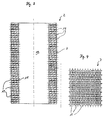
- a burner element 1 shown in FIG. 1 exists from a substantially hollow cylindrical Ceramic jacket 2, which consists of six plate-shaped ceramic elements 3, which are arranged with respect to one another, that they form a closed polygon. End the burner element 1 each has an annular element 4 or 5, which are U-shaped in cross section are, the two legs 6 of the annular Element 4 or 5 on the outer surface 7 of the ceramic jacket 2 concerns.
- the annular element 5 has one in its Center arranged bore 8 at least two in a uniform Distance to the bore 8 arranged openings 9, through which a gas-air mixture in the interior 10 of the Burner element 1 flows.
- the inflow direction of the gas-air mixture is represented by the arrows 11.
- the annular element 4 has compared to the annular Element 5 only one arranged in its center Bore 12, which is coaxial with the bore 8 in the annular Element 5 is arranged and which holes 8th and 12 are penetrated by a threaded rod 13.
- the Threaded rod 13 has a screwed on the outside Mother 14, which each have a Washer 15 on the end face 16 of the annular Elements 4 and 5 are supported.
- the threaded rod 13 forms the nuts 14 and the washers 15 a tie rod.
- distributor element 17 In the immediate area of the annular element 5 inside the interior 10 there is a distributor element 17 the threaded rod 13 attached, which distributor element 17th the gas-air mixture flowing in the direction of arrows 11 evenly on the inner wall 18 of the ceramic jacket 2 distributed so that the gas-air mixture through a variety of passage channels 19 in the area of the outer surface 7 arrives where the gas-air mixture for heating is burned.
- the passage channels 19 are evenly spaced from one another over the entire outer surface 7 of the burner element 1 distributed so that the passage channels 19 form a pinhole image.
- the flow direction of the gas-air mixture from the interior 10 through the passage channels 19 is through the arrows 20 indicated.
- FIG. 2 is a second embodiment of the burner element 1, which differs only from the first embodiment of the burner element 1 according to FIG. 1 distinguishes that some of the through channels 19 in one dome-shaped opening 21 which ends in the surface area the outer surface 7 are arranged.
- the respective ceramic jackets 2 are two embodiments shown in FIGS. 1 and 2. It can be clearly seen that the ceramic jacket 2 has an interior 10 open on both sides, which 1 and 2 by the annular elements 4th or 5 is completed. 4 and 6 show a section of the surface of the Outer lateral surface 7, which can be clearly seen in FIG. 4 is that the passage channels 19 have the same diameter, the passageways 19 overall a close-knit Form pinhole pattern. In comparison, the Fig. 6 additionally the arrangement of the dome-shaped Openings, each seven adjacent Combine passage channels 19. The surface of the 5 is the outer surface 7 of the ceramic shell 2 thus structured, whereas the surface of the Outer lateral surface 7 of the ceramic jacket 2 according to FIG. 3 a has a smooth surface.
- FIG. 7 is the outer surface 7 of the ceramic shell 2 in essentially corresponding to the lateral surface of a cylinder formed, whereas the inner wall 18 of the ceramic jacket 2 is polygonal.
- the neighboring ceramic elements 3 are mitered along their longitudinal edges 22 worked and in such a way that the longitudinal edges 22 of the Ceramic elements 3 radially to the outer surface 7 of the Ceramic jacket 2 run. Between neighboring ceramic elements 3 is also in the outer surface 7 in Area of the longitudinal edges 22 each in the longitudinal direction of the ceramic jacket 2 extending groove-shaped depression ordered.
- the individual ceramic elements 3 according to the embodiments 7 and 8 are on the one hand by the annular Elements 4 and 5 connected together. On the other hand can between the adjacent ceramic elements 3 Adhesive to be applied to the longitudinal edges 22, the Adjacent ceramic elements 3 glued together.
- FIGS. 9 and 10 differ In contrast, the embodiments according to FIGS. 7 and 8 in that between adjacent ceramic elements 3, a ceramic seal 24 is arranged.
- This Seals 24 serve to seal the neighboring ones Ceramic elements 3 made exclusively by the front arranged ring-shaped elements 4 and 5 with each other are connected.
- a burner element 1 according to FIG. 1 and / or 2 made of ceramic material for a radiant burner, especially for an infrared radiation burner, that with liquid or gaseous, in particular fossil fuels can be operated, it is provided that several, preferably six ceramic elements 3 in one closed polygon arranged and interconnected will.
- the originally cuboid ceramic elements 3 on its outer lateral surface 7 in the form of a segment of a circular arc sanded and then the longitudinal edges 22 of each ceramic element 3 mitred will.
- the Longitudinal edges 22 with a temperature-resistant ceramic adhesive are coated before the longitudinal edges 22 are adjacent Ceramic elements 3 are glued together.
- the ceramic element 2 with the two can annular elements 4 and 5 are provided at the ends, which are then clamped together via the threaded rod 13 . It should be ensured that the on the Ceramic elements 3 transmitted axial pressure not too high is, so that damage to the Ceramic elements 3 can not be done.
- Ceramic between adjacent ceramic elements Seals 24 are arranged.
- This ceramic Seals 24 consist of mat-like structures, which the space between adjacent ceramic elements 3 seal.
- the ceramic elements 3 in a first step their outer lateral surfaces 7 in the shape of a circular arc grind, then the ground ceramic elements 3 to assemble the ceramic jacket 2 and finally the at this point, the inner wall is still polygonal 18 parallel to the outer surface 7 to grind.
- advantage this latter possibility is that a more uniform Result achievable in the area of the inner wall 18 is, whereas the advantage of the former possibility the inventive method of producing an inventive Burner element 1 is that the grinding the individual ceramic elements 3 technically less expensive is.
Abstract
Description
Die Erfindung betrifft ein Brennerelement in im wesentlichen rohrförmiger Ausgestaltung aus keramischem Material für einen Strahlungsbrenner, insbesondere Infrarotstrahlungsbrenner, der mit flüssigen oder gasförmigen, insbesondere fossilen Brennstoffen betreibbar ist.The invention relates essentially to a burner element tubular design made of ceramic material for a radiation burner, in particular infrared radiation burner, that with liquid or gaseous, in particular fossil fuels can be operated.
Derartige Brennerelemente sind aus der Technik bekannt. Beispielsweise offenbart die EP 0 536 706 A2 ein Verfahren zum Herstellen eines Flammenhalters für einen Strahlungsbrenner und einen nach diesem Verfahren hergestellten Flammenhalter. Dieser vorbekannte Flammenhalter für Strahlungsbrenner für flüssige oder gasförmige Brennstoffe besteht aus einem keramischen Formkörper, der im Plasmaspritzverfahren aufgebaut ist. In diesem plasmakeramischen Formkörper sind mittels Laserstrahl Durchtrittskanäle für das Brennstoff-Luftgemisch gebohrt. Nachteil dieses vorbekannten Flammenhalters ist, daß seine Herstellung sehr aufwendig ausgebildet ist und daß hierdurch sehr hohe Produktionskosten entstehen.Such burner elements are known from the art. For example, EP 0 536 706 A2 discloses a method for producing a flame holder for a radiation burner and one made by this method Flame holder. This well known flame holder for Radiation burner for liquid or gaseous fuels consists of a ceramic molded body using the plasma spray process is constructed. In this plasma ceramic Shaped bodies are passage channels for using a laser beam the fuel-air mixture drilled. Disadvantage of this previously known Flame holder is that its manufacture is very is complex and that as a result very high Production costs arise.
Ferner ist aus der EP 0 382 674 A2 ein Infrarotstrahlungsbrenner bekannt, der aus einem korrosionsbeständigen Siebmantel besteht, auf welchem eine dicke, poröse Ummantelung aus keramischen Fasern aufgebracht ist. Auch dieser vorbekannte Strahlungsbrenner hat den Nachteil, daß seine Herstellung aufwendig, technisch kompliziert und damit sehr kostenintensiv ist. Ferner besteht bei diesem vorbekannten Strahlungsbrenner die Gefahr, daß durch das Aufbringen der dicken, porösen Ummantelung aus keramischen Fasern eine im wesentlichen ungleichmäßige Ummantelung geschaffen wird, die insbesondere zu einer ungleichmäßigen Verbrennung auf der Mantelfläche führen kann. Furthermore, EP 0 382 674 A2 is an infrared radiation burner known from a corrosion-resistant screen jacket on which there is a thick, porous coating is applied from ceramic fibers. This well-known one too Radiation burner has the disadvantage that its manufacture complex, technically complicated and therefore very much is expensive. Furthermore, this is known Radiation burner the risk that by applying the thick, porous sheathing made of ceramic fibers substantially uneven covering is created, which in particular lead to uneven combustion the outer surface can lead.
Ausgehend von diesem Stand der Technik liegt der Erfindung die Aufgabe zugrunde, ein Brennerelement dahingehend weiterzubilden, daß es in einfacher und kostengünstiger Weise herstellbar ist, wobei über die gesamte Außenoberfläche des Brennerelementes eine im wesentlichen gleichmäßige Verbren-nung sichergestellt sein soll.Based on this prior art, the object of the invention is to further develop a burner element in such a way that it can be produced in a simple and cost-effective manner, with essentially uniform combustion being ensured over the entire outer surface of the burner element.
Die Lösung dieser Aufgabenstellung sieht mehrere miteinander verbundene, im wesentlichen gleich ausgebildete plattenförmige Keramikelemente vor, die über ihre gesamte Fläche eine Vielzahl von Durchtrittskanälen für das Brennstoff-Luftgemisch aufweisen, wobei die Keramikelemente in einem geschlossenen Polygonzug zueinander angeordnet sind.The solution to this problem provides several interconnected, essentially identically designed plate-shaped ceramic elements which have a large number of passage channels for the fuel-air mixture over their entire surface, the ceramic elements being arranged in a closed polygonal pattern.
Demzufolge besteht das erfindungsgemäße Brennerelement aus mehreren quaderförmigen Keramikelementen, wobei benachbart zueinander angeordnete Keramikelemente an ihren Längskanten miteinander verbunden sind. Die zusammengefügten Keramikelemente bilden somit ein Brennerelement in im wesentlichen rohrförmiger Ausgestaltung, wobei der Polygonzug mit zunehmender Anzahl von Keramikelementen sich zunehmend einer zylindrischen Ausgestaltung des Brennerelementes annähert.Accordingly, the burner element according to the invention consists of several cuboid ceramic elements, being adjacent ceramic elements arranged to each other on their longitudinal edges are interconnected. The assembled ceramic elements thus essentially form a burner element tubular design, the polyline with increasing Number of ceramic elements increasingly one approximates cylindrical configuration of the burner element.
Nach einem weiteren Merkmal der Erfindung ist vorgesehen, daß die Keramikelemente im Bereich ihrer aneinander angrenzenden Kanten auf der Außenmantelfläche abgerundet sind. Durch diese Ausgestaltung ist es möglich, daß bereits bei Verwendung von wenigen Keramikelementen, beispielsweise von sechs Keramikelementen, eine im wesentlichen zylindrische Außengestalt des Brennerelementes erzielt wird. Durch die zylindrische Außenmantelfläche wird eine gleichmäßige Verbrennung auf der Außenmantelfläche des Brennerelementes bereitgestellt, so daß über die gesamte Außemantelfläche des Brennerelementes gleiche bzw. gleichbleibende Bedingungen, insbesondere Verbrennungstemperaturen herrschen. According to a further feature of the invention, that the ceramic elements in the area of their adjacent Edges are rounded on the outer surface. This configuration makes it possible that already at Use of a few ceramic elements, for example from six ceramic elements, one essentially cylindrical External shape of the burner element is achieved. Through the cylindrical outer surface becomes an even combustion on the outer surface of the burner element provided so that over the entire outer surface identical or constant conditions of the burner element, combustion temperatures prevail in particular.
Ergänzend kann bei einem erfindungsgemäßen Brennerelement vorgesehen sein, daß die Keramikelemente auf ihrer Innenfläche konkav ausgebildet sind. Es ergibt sich dann eine zylinderförmige Öffnung innerhalb des Polygonzuges der Keramikelemente. Auch diese Ausgestaltung dient der Erzielung einer gleichmäßigen Verbrennung auf der Außenmantelfläche des Brennerelementes.In addition, in a burner element according to the invention be provided that the ceramic elements on their inner surface are concave. Then there is one cylindrical opening within the traverse of the Ceramic elements. This configuration also serves Achieve uniform combustion on the outer surface of the burner element.
Nach einem weiteren Merkmal der Erfindung ist vorgesehen, daß die Keramikelemente an ihren aneinander angrenzenden Kanten auf Gehrung gearbeitet sind, vorzugsweise derart, daß die Verbindungsebene zwischen benachbarten Keramikelementen radial zu einer Öffnung im Brennerelement angeordnet sind. Diese Ausgestaltung hat insbesondere den Vorteil, daß die einzelnen Keramikelemente in einfacher Weise und paßgenau aneinander angesetzt werden können, wobei die Gehrung dazu führt, daß eine große Befestigungsfläche benachbarter Keramikelemente entsteht.According to a further feature of the invention, that the ceramic elements on their adjacent Mitred edges are worked, preferably such that the connection plane between adjacent ceramic elements arranged radially to an opening in the burner element are. This configuration has in particular Advantage that the individual ceramic elements in simpler Can be attached to one another in a manner that fits perfectly, the miter leads to a large mounting surface neighboring ceramic elements are created.
Die Keramikelemente sind vorzugsweise miteinander verbunden, insbesondere verklebt, wobei beispielsweise ein temperaturbeständiger Keramikkleber verwendet wird. Alternativ oder ergänzend hierzu kann vorgesehen sein, daß zwischen benachbarten Keramikelementen ein insbesondere als Matte ausgebildetes Keramikdichtelement als Verbinder angeordnet ist.The ceramic elements are preferably together connected, in particular glued, for example a temperature-resistant ceramic adhesive is used. Alternatively or additionally, it can be provided that between adjacent ceramic elements a particularly as Matte ceramic sealing element as a connector is arranged.
Zur weiteren Verbesserung und zur Erhöhung der Stabilität der Verbindung zwischen den Keramikelementen kann vorgesehen sein, daß die Keramikelemente mit zumindest einem im wesentlichen ringförmigen, d. h. an die Außenkontur der Keramikelemente angepaßtes Element verbunden sind, das vorzugsweise an einem axialen Ende der Keramikelemente aufgesteckt ist. Es kann aber auch vorgesehen sein, daß jedes axiale Ende des Keramikelementes ein derartiges Element auf-weist. To further improve and increase stability the connection between the ceramic elements can be provided be that the ceramic elements with at least one in substantially annular, d. H. to the outer contour of the Ceramic elements matched element are connected preferably at an axial end of the ceramic elements is attached. But it can also be provided that each axial end of the ceramic element one Element has.
Vorzugsweise besteht das ringförmige Element aus einem Material, dessen Wärmeausdehnungskoeffizient im wesentlichen mit dem Wärmeausdehnungskoeffizienten des keramischen Materials übereinstimmt, so daß bei Erwärmung der Keramikelemente und der ringförmigen Elemente die Spannungen zwischen diesen beiden Bauteilen möglichst gering gehalten werden und gleichzeitig eine im Verhältnis zu den Keramikelementen größere oder kleinere Ausdehnung des ringförmigen Elementes nicht dazu führt, daß die Haltekräfte des ring-förmigen Elementes zu stark verringert werden oder der Druck auf die Keramikelemente vergrößert wird.The annular element preferably consists of a Material whose coefficient of thermal expansion is essentially with the coefficient of thermal expansion of ceramic material matches, so that when heated the ceramic elements and the annular elements Tensions between these two components as possible be kept low and at the same time one in proportion to the ceramic elements larger or smaller expansion of the annular element does not cause the Holding forces of the ring-shaped element reduced too much or the pressure on the ceramic elements is increased becomes.
Das ringförmige Element kann im Querschnitt L-förmig oder U-förmig ausgebildet sein, wobei die U-förmige Ausbildung des ringförmigen Elementes insbesondere den Vorteil hat, daß die beiden freien Schenkel des U-förmig ausgebildeten Elementes die Keramikplatten beidseitig, d. h. sowohl auf der Außenmantelfläche als auch auf der Innenmantelfläche des Brennerelementes halten.The annular element can be L-shaped in cross section or Be U-shaped, the U-shaped configuration of the annular element has the particular advantage that the two free legs of the U-shaped Elementes the ceramic plates on both sides, d. H. both on the outer surface as well as on the inner surface hold the burner element.
Das ringförmige Element kann ferner zur Verbindung axial benachbarter Keramikelemente im Querschnitt T-förmig oder H-förmig ausgebildet sein. Auch in diesem Fall hat das H-förmig ausgebildete ringförmige Element die voranstehend genannten Vorteile hinsichtlich der besseren Halterung der Keramikelemente.The annular element can also be axially connected neighboring ceramic elements in cross-section T-shaped or Be H-shaped. In this case, too, it is H-shaped trained annular element the above mentioned advantages with regard to the better mounting of the Ceramic elements.
Nach einem weiteren Merkmal der Erfindung ist vorgesehen, daß das ringförmige Element einen die Öffnung abdeckenden Deckel aufweist. Ferner ist nach einem weiteren Merkmal der Erfindung vorgesehen, daß zwei an den axialen Enden angeordnete ringförmige Elemente miteinander, beispielsweise über einen Zuganker verbunden sind. Über den Zuganker, der beispielsweise aus einer Gewindestange bestehen kann, welche in entsprechende Gewindemuttern geschraubt ist, können die beiden an den axialen Enden des Brennerlementes angeordneten ringförmigen Elemente aufeinander zu- oder voneinander wegbewegt werden, so daß entweder eine Verspannung der Keramikelemente erzielt wird oder daß zu große Spannungen über eine Lockerung des Zugankers reduziert werden.According to a further feature of the invention, that the annular element covers an opening Has lid. Furthermore, according to another feature Invention provided that two arranged at the axial ends annular elements with each other, for example are connected via a tie rod. About the tie rod, the can consist of a threaded rod, for example, which is screwed into corresponding threaded nuts, can the two at the axial ends of the burner element arranged annular elements towards each other or be moved away from each other, so that either a bracing the ceramic elements is achieved or that too large Tension is reduced by loosening the tie rod will.
Als alternative Verbindung von axial benachbart angeordneten Keramikelementen kann vorgesehen sein, daß in axialer Richtung benachbart angeordnete Keramikelemente über eine Nut-Feder-Verbindung formschlüssig miteinander verbunden sind. Hierbei kann auch vorgesehen sein, daß die Nut-Feder-Verbindung in Kombination mit einem temperaturbeständigen Klebstoff Verwendung findet.As an alternative connection from axially adjacent arranged ceramic elements can be provided that in Ceramic elements arranged adjacent to one another in the axial direction form-fitting with each other via a tongue and groove connection are connected. It can also be provided that the Tongue and groove in combination with a temperature-resistant adhesive is used.
Die Durchtrittskanäle in den Keramikelementen sind vorzugsweise als Nadellochbild ausgebildet und angeordnet. Um eine gleichmäßige Verbrennung an der Außenmantelfläche des Brennerelementes zu erzielen, sind die Durchmesser der Durchtrittskanäle in Abhängigkeit der Materialstärke des Keramikelementes ausgebildet, so daß sich ein gleichmäßiger Widerstand in allen Durchtrittskanälen ergibt. Hierbei ist insbesondere darauf hinzuweisen, daß bei Keramikelementen, die bei der Montage des Brennerelementes quaderförmig ausgebildet sind und welche anschließend an ihren Längskantenbereich derart geschliffen werden, daß ein im wesentlichen zylinderförmiges Brennerelement entsteht, die Durchtrittskanäle im Randbereich der Keramikelemente kürzer ausgebildet sind, als im Mittelbereich der Keramikelemente, so daß sich im Mittelbereich ein längerer Durchströmweg für die Brennstoffe ergibt.The passage channels in the ceramic elements are preferred formed and arranged as a pinhole pattern. To one uniform combustion on the outer surface of the To achieve burner element, the diameter of the Passage channels depending on the material thickness of the Ceramic element formed so that there is a uniform Resistance in all passageways results. Here is especially to point out that with ceramic elements, which are cuboid in the assembly of the burner element and which are next to their longitudinal edge area be ground so that a substantially cylindrical burner element is created, the passage channels Shorter in the edge area of the ceramic elements are, as in the central region of the ceramic elements, so that there is a longer flow path for which gives fuels.
In alternativer und bevorzugter Ausführungsform ist vorgesehen, daß die Keramikelemente über ihre gesamte Fläche eine gleichmäßige Materialstärke aufweisen. Auch diese Ausführungsform weist den Vorteil auf, daß an der Außenmantelfläche des Brennelementes gleiche Verbrennungsparameter herrschen, die eine gleichmäßige Verbrennung der Brennstoffe ermöglichen.In an alternative and preferred embodiment, that the ceramic elements over their entire area have a uniform material thickness. This embodiment too has the advantage that on the outer surface of the fuel element have the same combustion parameters prevail, the even combustion of the fuels enable.
Um auch innerhalb des Polygonzuges bzw. des Brennerelementes eine gleichmäßige Verteilung des zugeführten Brennstoffes zu erzielen, ist nach einem weiteren Merkmal der Erfindung vorgesehen, daß in der vom Polygonzug gebildeten Öffnung des Brennerelementes ein Verteilerelement angeordnet ist. Das Verteilerelement ist vorzugsweise im Bereich der Einzugsöffnung der Brennstoffe angeordnet, so daß möglichst unmittelbar nach Einströmen des Brennstoffes bzw. Brennstoffgemisches in das Brennelement eine vergleichmäßigte Verteilung des Brennstoffes erzielt wird. Hierdurch wird ebenfalls die gleichmäßige Verbrennung des Brennstoffes auf der Außen-mantelfläche des Brennelementes gefördert.To also within the polyline or the burner element an even distribution of the fuel supplied To achieve, is another feature of Invention provided that in the polygon Opening the burner element arranged a distributor element is. The distributor element is preferably in the area the feed opening of the fuels arranged so that as soon as possible after inflowing the fuel or Fuel mixture in the fuel assembly even distribution of the fuel is achieved. This also ensures the even combustion of the Fuel on the outer surface of the fuel assembly promoted.
Vorzugsweise ist das Verteilerelement am Zuganker befestigt, da sich hierdurch eine einfache und kostengünstige Ausgestaltung und Anordnung des Verteilerelementes ergibt.The distributor element is preferably on the tie rod attached, as this is a simple and inexpensive Design and arrangement of the distributor element results.
Die Oberfläche der einzelnen plattenförmigen Keramikelemente kann nach einem weiteren Merkmal der Erfindung strukturiert ausgebildet sein. Vorzugsweise endet zumindest ein Teil der Durchtrittskanäle im Bereich der Oberfläche der plattenförmigen Keramikelemente in vorzugsweise kalottenförmig ausgebildeten Öffnungen, deren Durchmesser größer ist als der Durchmesser der Durchtrittskanäle.The surface of the individual plate-shaped ceramic elements can according to another feature of the invention be structured. Preferably at least ends part of the passage channels in the area of the surface of the plate-shaped ceramic elements in preferably dome-shaped openings, their diameter is larger than the diameter of the passage channels.
Die Erfindung betrifft ferner ein Verfahren zur Herstellung eines im wesentlichen ringförmigen Brennerelementes aus keramischem Material für einen Strahlungsbrenner, insbesondere für einen Infrarotstrahlungsbrenner, der mit flüssigen oder gasförmigen, insbesondere fossilen Brennstoffen betreibbar ist, wobei mehrere plattenförmige Keramikelemente in einem geschlossenen Polygonzug angeordnet und miteinander verbunden werden.The invention further relates to a method of manufacture a substantially annular burner element ceramic material for a radiant burner, in particular for an infrared radiation burner that works with liquid or gaseous, especially fossil fuels is operable, with several plate-shaped ceramic elements arranged in a closed polygon and with each other get connected.
Vorzugsweise werden die Keramikelemente im Bereich ihrer aneinander angrenzenden Kanten kreisbogenabschnittförmig geschliffen, um eine möglichst gleichmäßig abgerundete, im wesentlichen zylindrische Außenmantelfläche zu erzielen.The ceramic elements are preferably in the region of their adjacent edges in the form of a segment of an arc ground in order to make a to achieve a substantially cylindrical outer surface.
Gemäß einer ersten Ausführungsform des erfindungsgemäßen Verfahrens ist vorgesehen, daß die Keramikelemente vor dem Zusammensetzen des Brennerelementes an der Außenfläche und / oder der Innenfläche kreisbogenabschnittförmig geschliffen werden, so daß sich nach dem Zusammensetzen der Keramikelemente ein im Querschnitt im wesentlichen hohlzylindrisch ausgebildetes Brennerelement ergibt. Alternativ zu dieser Ausführungsform ist nach einer zweiten Ausführungsform vorgesehen, daß die Keramikelemente nach dem Zusammensetzen des Brennerelementes an der Außenfläche und / oder Innenfläche kreisbogenabschnittförmig geschliffen werden. Diese Ausgestaltung des erfindungsgemäßen Verfahrens hat sich insbesondere bei der Herstellung von Brennerelementen aus zumindest sechs oder acht Keramikelementen bewährt, da sich dann aufgrund der Annäherung der zu-einander angeordneten Keramikelemente bereits ein im wesentlichen im Querschnitt hohlzylindrisch ausgebildeter Körper ergibt, wobei dann die notwendigen Schleif-arbeiten relativ gering sind.According to a first embodiment of the invention The method provides that the ceramic elements before Assemble the burner element on the outer surface and / or ground the inner surface in the form of a circular arc so that after assembling the Ceramic elements are essentially hollow cylindrical in cross section trained burner element results. Alternatively to this embodiment is according to a second embodiment provided that the ceramic elements after Assemble the burner element on the outer surface and / or the inner surface is ground in the form of a circular arc will. This embodiment of the invention Process has proven particularly useful in the manufacture of Burner elements made of at least six or eight ceramic elements proven, because then due to the approximation of the ceramic elements arranged in relation to one another already in essentially hollow-cylindrical in cross section Body results, in which case the necessary grinding work are relatively small.
Die Keramikelemente werden vorzugsweise miteinander verklebt, um eine ausreichende Festigkeit des Brennerelementes zu erzielen. Es hat sich aber auch bewährt, zwischen den Keramikelementen keramische Dichtkörper anzuordnen, die ebenfalls zu einer kraftschlüssigen Verbindung benachbarter Keramikelemente führen und insbesondere den Übergangsbereich benachbarter Keramikelemente abdichten. The ceramic elements are preferably together glued to a sufficient strength of the burner element to achieve. But it has also proven itself to arrange ceramic sealing bodies between the ceramic elements, which also form a non-positive connection lead adjacent ceramic elements and especially the Seal the transition area between adjacent ceramic elements.
Schließlich ist nach einem weiteren Merkmal der Erfindung vorgesehen, daß auf beiden axialen Enden der Keramikelemente jeweils ein im wesentlichen ringförmiges Element aufgesetzt wird, welches die Keramikelemente miteinander verbindet, ohne daß eine erhöhte Spannung auf die Keramikelemente übertragen wird.Finally, another feature of the invention provided that on both axial ends of the ceramic elements each have an essentially annular element is placed, which the ceramic elements together connects without an increased tension on the Ceramic elements is transferred.
Weitere Merkmale und Vorteile der Erfindung ergeben sich aus der nachfolgenden Beschreibung der zugehörigen Zeichnung, in der bevorzugte Ausführungsformen des erfindungsgemäßen Brennerelementes dargestellt sind.Further features and advantages of the invention result from the following description of the related Drawing, in the preferred embodiments of the invention Burner element are shown.
In der Zeichnung zeigen:
Ein in der Fig. 1 dargestelltes Brennerelement 1 besteht
aus einem im wesentlichen hohlzylindrisch ausgebildeten
Keramikmantel 2, welcher aus sechs plattenförmigen Keramikelementen
3 besteht, die derart zueinander angeordnet sind,
daß sie einen geschlossenen Polygonzug bilden. Endseitig
weist das Brennerelement 1 jeweils ein ringförmiges Element
4 bzw. 5 auf, welche im Querschnitt U-förmig ausgebildet
sind, wobei die beiden Schenkel 6 des ringförmigen
Elementes 4 bzw. 5 an der Außenmantelfläche 7 des Keramikmantels
2 anliegen.A
Das ringförmige Element 5 weist neben einer in seinem
Zentrum angeordneten Bohrung 8 zumindest zwei in gleichmäßigem
Abstand zur Bohrung 8 angeordnete Öffnungen 9 auf,
durch welche ein Gas-Luftgemisch in den Innenraum 10 des
Brennerelementes 1 einströmt. Die Einströmrichtung des Gas-Luftgemisches
ist durch die Pfeile 11 dargestellt.The
Das ringförmige Element 4 weist im Vergleich zu dem ringförmigen
Element 5 lediglich eine in seinem Zentrum angeordnete
Bohrung 12 auf, die koaxial zur Bohrung 8 im ringförmigen
Element 5 angeordnet ist und welche Bohrungen 8
und 12 von einer Gewindestange 13 durchgriffen sind. Die
Gewindestange 13 weist jeweils außenseitig eine aufgeschraubte
Mutter 14 auf, welche sich jeweils über eine
Unterlegscheibe 15 auf der Stirnfläche 16 der ringförmigen
Elemente 4 bzw. 5 abstützt. Die Gewindestange 13 bildet mit
den Muttern 14 und den Unterlegscheiben 15 einen Zuganker.The
Im unmittelbaren Bereich des ringförmigen Elementes 5
innerhalb des Innenraumes 10 ist ein Verteilerelement 17 an
der Gewindestange 13 befestigt, welches Verteilerelement 17
das in Richtung der Pfeile 11 einströmende Gas-Luftgemisch
gleichmäßig an der Innenwandung 18 des Keramikmantels 2
verteilt, so daß das Gas-Luftgemisch durch eine Vielzahl
von Durchtrittskanälen 19 in den Bereich der Außenmantelfläche
7 gelangt, wo das Gas-Luftgemisch zur Erwärmung
verbrannt wird.In the immediate area of the
Die Durchtrittskanäle 19 sind in gleichmäßigem Abstand zueinander
über die gesamte Außenmantelfläche 7 des Brennerelementes
1 verteilt angeordnet, so daß die Durchtrittskanäle
19 ein Nadellochbild bilden.The
Die Ausströmrichtung des Gas-Lufgemisches aus dem Innenraum
10 durch die Durchtrittskanäle 19 ist durch die Pfeile 20
angedeutet.The flow direction of the gas-air mixture from the interior
10 through the
In der Fig. 2 ist eine zweite Ausführungsform des Brennerelementes
1 dargestellt, die sich nur insofern von der
ersten Ausführungsform des Brennerelementes 1 gemäß Fig. 1
unterscheidet, daß einige der Durchtrittskanäle 19 in einer
kalottenförmigen Öffnung 21 enden, welche im Oberflächenbereich
der Außenmantelfläche 7 angeordnet sind.2 is a second embodiment of the
In den Fig. 3 und 5 sind die jeweiligen Keramikmäntel 2 der
beiden Ausführungsformen gemäß den Fig. 1 und 2 dargestellt.
Hierbei ist deutlich zu erkennen, daß der Keramikmantel
2 einen beidseitig offenen Innenraum 10 hat, welcher
gemäß den Fig. 1 und 2 durch die ringförmigen Elemente 4
bzw. 5 abgeschlossen wird.
Die Fig. 4 und 6 zeigen einen Ausschnitt der Oberfläche der
Außenmantelfläche 7, wobei in Fig. 4 deutlich zu erkennen
ist, daß die Durchtrittskanäle 19 gleiche Durchmesser aufweisen,
wobei die Durchtrittskanäle 19 insgesamt ein engmaschiges
Nadellochbild bilden. Im Vergleich dazu zeigt die
Fig. 6 ergänzend die Anordnung der kalottenförmigen
Öffnungen, die jeweils sieben benachbart angeordnete
Durchtrittskanäle 19 zusammenfassen. Die Oberfläche der
Außenmantelfläche 7 des Keramikmantels 2 gemäß Fig. 5 ist
somit strukturiert ausgebildet, wogegen die Oberfläche der
Außenmantelfläche 7 des Keramikmantels 2 gemäß Fig. 3 eine
glatte Oberfläche aufweist.
In den Fig. 7 bis 11 sind verschiedene Ausführungsformen
des Keramikmantels 2 im Querschnitt dargestellt. Gemäß Fig.
7 ist die Außenmantelfläche 7 des Keramikmantels 2 im
wesentlichen entsprechend der Mantelfläche eines Zylinders
ausgebildet, wogegen die Innenwandung 18 des Keramikmantels
2 polygonal ausgebildet ist. Die benachbarten Keramikelemente
3 sind entlang ihrer Längskanten 22 auf Gehrung
gearbeitet und zwar derart, daß die Längskanten 22 der
Keramikelemente 3 radial zur Außenmantelfläche 7 des
Keramikmantels 2 verlaufen. Zwischen benachbarten Keramikelementen
3 ist darüberhinaus in der Außenmantelfläche 7 im
Bereich der Längskanten 22 jeweils eine in Längsrichtung
des Keramikmantels 2 verlaufende nutförmige Vertiefung
ange-ordnet.
Die einzelnen Keramikelemente 3 gemäß den Ausführungsformen
nach den Fig. 7 und 8 sind einerseits durch die ringförmigen
Elemente 4 und 5 miteinander verbunden. Andererseits
kann zwischen den benachbarten Keramikelementen 3 ein
Kleber auf die Längskanten 22 aufgetragen sein, der die
benachbarten Keramikelemente 3 miteinander verklebt. 3 and 5, the respective
Die Ausführungsformen gemäß den Fig. 9 und 10 unterscheiden
sich demgegenüber von den Ausführungsformen gemäß den Fig.
7 und 8 dadurch, daß zwischen benachbarten Keramikelementen
3 eine keramische Dichtung 24 angeordnet ist. Diese
Dichtungen 24 dienen der Abdichtung der benachbarten
Keramik-elemente 3, die ausschließlich durch stirnseitig
angeordne-te ringförmige Elemente 4 und 5 miteinander
verbunden sind.The embodiments according to FIGS. 9 and 10 differ
In contrast, the embodiments according to FIGS.
7 and 8 in that between adjacent
Zur Herstellung eines Brennerelementes 1 gemäß den Fig. 1
und / oder 2 aus keramischem Material, für einen Strahlungsbrenner,
insbesondere für einen Infrarotstrahlungsbrenner,
der mit flüssigen oder gasförmigen, insbesondere
fossilen Brennstoffen betreibbar ist, ist vorgesehen, daß
mehrere, vorzugsweise sechs Keramikelemente 3 in einem
geschlossenen Polygonzug angeordnet und miteinander verbunden
werden. Hierzu kann beispielsweise vorgesehen sein,
daß die ursprünglich quaderförmig ausgebildeten Keramikelemente
3 an ihrer Außenmantelfläche 7 kreisbogenabschnittförmig
geschliffen und anschließend die Längskanten
22 eines jeden Keramikelementes 3 auf Gehrung geschnitten
werden. In einem nachfolgenden Schritt können dann die
Längskanten 22 mit einem temperaturbeständigen Keramikkleber
bestrichen werden, bevor die Längskanten 22 benachbarter
Keramikelemente 3 miteinander verklebt werden.
Ergänzend kann hierzu das Keramikelement 2 mit den beiden
ringförmigen Elementen 4 und 5 endseitig versehen werden,
die anschließend über die Gewindestange 13 miteinander verspannt
werden, wobei darauf zu achten ist, daß der auf die
Keramikelemente 3 übertragene axiale Druck nicht zu hoch
ist, so daß im warmen Zustand Beschädigungen an den
Keramikelementen 3 nicht erfolgen können.To produce a
Alternativ zu dem voranstehend genannten Klebemittel können
zwischen benachbarten Keramikelementen 3 keramische
Dichtungen 24 angeordnet werden. Diese keramischen
Dichtungen 24 bestehen aus mattenartigen Gebilden, welche
den Zwischenraum zwischen benachbarten Keramikelementen 3
abdichten. Bei dieser konstruktiven Ausgestaltung des
Brennerelementes 1 ist es zwingend notwendig, daß die
Keramikelemente 3 über die ringförmigen Elemente 4 und 5
miteinander verbunden werden, wenn nicht zusätzlich ein
Kleber auf die Längskanten 22 der Keramikelemente 3
aufgetragen wird.As an alternative to the
Um einen Keramikmantel 2 zu erzielen, der entsprechend den
Ausführungsformen gemäß den Fig. 8 und 11 ausgebildet ist,
ist es notwendig, daß nicht nur die Außenmantelfläche 7 der
einzelnen Keramikelemente 3 kreisbogenabschnittförmig
geschliffen werden, sondern daß auch die Innenwandung 18 in
entsprechender Weise ausgebildet wird. Hierzu sind generell
zwei Möglichkeiten vorgesehen. Zum einen besteht die Möglichkeit,
daß die einzelnen Keramikelemente 3 vor dem
Zusammenfügen der Keramikelemente 3 zum Keramikmantel 2
sowohl auf der Außenmantelfläche 7 als auch auf der Innenwandung
18 schleifend bearbeitet werden, um einen kreisbogenabschnittförmigen
Teil des Keramikmantels 2 zu
schaffen. Andererseits besteht die alternative Möglichkeit,
die Keramikelemente 3 in einem ersten Schritt an
ihren Außenmantelflächen 7 kreisbogenabschnittförmig zu
schleifen, anschließend die geschliffenen Keramikelemente 3
zum Keramikmantel 2 zusammenzufügen und schließlich die zu
diesem Zeitpunkt noch polygonal ausgebildete Innenwandung
18 parallel zur Außenmantelfläche 7 zu schleifen. Vorteil
dieser zuletzt genannten Möglichkeit ist, daß ein gleichmäßigeres
Ergebnis im Bereich der Innenwandung 18 erzielbar
ist, wogegen der Vorteil der erstgenannten Möglichkeit
der erfindungsgemäßen Herstellungsweise eines erfindungsgemäßen
Brennerelementes 1 darin liegt, daß das Beschleifen
der einzelnen Keramikelemente 3 technisch weniger aufwendig
ist.To achieve a
Claims (29)
gekennzeichnet durch
mehrere miteinander verbundene, im wesentlichen gleich ausgebildete plattenförmige Keramikelemente (3), die über ihre gesamte Fläche eine Vielzahl von Durchtrittskanälen (19) für das Brennstoff-Luftgemisch aufweisen, wobei die Keramikelemente (3) in einem geschlossenen Polygonzug zueinander angeordnet sind.Burner element in an essentially tubular configuration made of ceramic material for a radiation burner, in particular infrared radiation burner, which can be operated with liquid or gaseous, in particular fossil, fuels,
marked by
a plurality of interconnected, essentially identically shaped plate-shaped ceramic elements (3) which have a large number of passage channels (19) for the fuel-air mixture over their entire surface, the ceramic elements (3) being arranged in a closed polygonal pattern.
dadurch gekennzeichnet,
daß die Keramikelemente (3) im Bereich ihrer aneinander angrenzenden Kanten (22) auf der Außenmantelfläche (7) abgerundet sind.Burner element according to claim 1,
characterized,
that the ceramic elements (3) are rounded in the region of their mutually adjacent edges (22) on the outer surface (7).
dadurch gekennzeichnet,
daß die Keramikelemente (3) auf ihrer Innenfläche (18) konkav ausgebildet sind.Burner element according to claim 1,
characterized,
that the ceramic elements (3) are concave on their inner surface (18).
dadurch gekennzeichnet,
daß die Keramikelemente (3) an ihren aneinander angrenzenden Kanten (22) auf Gehrung gearbeitet sind, vorzugsweise derart, daß die Verbindungsebene zwischen benachbarten Keramikelementen (3) radial zu einer Öffnung im Brennerelement (1) angeordnet sind. Burner element according to claim 1,
characterized,
that the ceramic elements (3) are mitred at their adjacent edges (22), preferably in such a way that the connection plane between adjacent ceramic elements (3) is arranged radially to an opening in the burner element (1).
dadurch gekennzeichnet,
daß die Keramikelemente (3) miteinander verbunden, vorzugsweise verklebt sind, wobei insbesondere ein temperaturbeständiger Keramikkleber verwendet wird.Burner element according to claim 1,
characterized,
that the ceramic elements (3) are connected, preferably glued, in particular using a temperature-resistant ceramic adhesive.
dadurch gekennzeichnet,
daß zwischen benachbarten Keramikelementen (3) ein insbesondere als Matte ausgebildetes Keramikdichtelement (24) als Verbinder angeordnet ist.Burner element according to claim 1,
characterized,
that a ceramic sealing element (24), in particular a mat, is arranged as a connector between adjacent ceramic elements (3).
dadurch gekennzeichnet,
daß die Keramikelemente (3) mit zumindest einem, im wesentlichen ringförmigen, d. h. an die Außenmantelfläche (7) der Keramikelemente (3) angepaßtes Element (4, 5) verbunden sind, das vorzugsweise an einem axialen Ende der Keramikelemente (3) aufgesteckt ist.Burner element according to claim 1,
characterized,
that the ceramic elements (3) are connected to at least one essentially ring-shaped element (4, 5) which is adapted to the outer lateral surface (7) of the ceramic elements (3) and which is preferably attached to an axial end of the ceramic elements (3).
dadurch gekennzeichnet,
daß das ringförmige Element (4, 5) aus einem Material besteht, dessen Wärmeausdehnungskoeffizient im wesentlichen mit dem Wärmeausdehnungskoeffizienten des keramischen Materials übereinstimmt.Burner element according to claim 7,
characterized,
that the annular element (4, 5) consists of a material whose coefficient of thermal expansion substantially corresponds to the coefficient of thermal expansion of the ceramic material.
dadurch gekennzeichnet,
daß das ringförmige Element (4, 5) im Querschnitt L-förmig oder U-förmig ausgebildet ist.Burner element according to claim 7,
characterized,
that the annular element (4, 5) is L-shaped or U-shaped in cross section.
dadurch gekennzeichnet,
daß das ringförmige Element (4, 5) zur Verbindung axial benachbarter Keramikelemente (3) im Querschnitt T-förmig oder H-förmig ausgebildet ist.Burner element according to claim 7,
characterized,
that the annular element (4, 5) for connecting axially adjacent ceramic elements (3) is T-shaped or H-shaped in cross section.
dadurch gekennzeichnet,
daß das ringförmige Element (4, 5) einen die Öffnung abdeckenden Deckel aufweist.Burner element according to claim 7,
characterized,
that the annular element (4, 5) has a cover covering the opening.
dadurch gekennzeichnet,
daß zwei an den axialen Enden angeordnete ringförmige Elemente (4, 5) miteinander, beispielsweise über einen Zuganker verbunden sind.Burner element according to claim 7,
characterized,
that two annular elements (4, 5) arranged at the axial ends are connected to one another, for example via a tie rod.
dadurch gekennzeichnet,
daß jedes Keramikelement (3) im Bereich seiner aneinander angrenzenden Kanten (22) eine Nut aufweist.Burner element according to claim 1,
characterized,
that each ceramic element (3) has a groove in the region of its adjacent edges (22).
dadurch gekennzeichnet,
daß in axialer Richtung benachbart angeordnete Keramikelemente (3) über Nut-Feder-Verbindungen formschlüssig miteinander verbunden sind.Burner element according to claim 1,
characterized,
that ceramic elements (3) arranged adjacent to one another in the axial direction are positively connected to one another via tongue and groove connections.
dadurch gekennzeichnet,
daß die Durchtrittskanäle (19) als Nadellochbild ausgebildet und angeordnet sind.Burner element according to claim 1,
characterized,
that the passage channels (19) are designed and arranged as a pinhole pattern.
dadurch gekennzeichnet,
daß die Durchmesser der Durchtrittskanäle (19) in Abhängigkeit der Materialstärke des Keramikelementes (3) ausgebildet sind, um einen gleichmäßigen Widerstand in allen Durchtrittskanälen (19) zu erzielen. Burner element according to claim 1,
characterized,
that the diameters of the passage channels (19) are designed as a function of the material thickness of the ceramic element (3) in order to achieve a uniform resistance in all passage channels (19).
dadurch gekennzeichnet,
daß die Keramikelemente (3) über ihre gesamte Fläche eine gleichmäßige Materialstärke aufweisen.Burner element according to claim 1,
characterized,
that the ceramic elements (3) have a uniform material thickness over their entire surface.
dadurch gekennzeichnet,
daß der Polygonzug aus einer geradzahligen Anzahl, vorzugsweise aus sechs, acht oder mehr Keramikelementen (3) besteht.Burner element according to claim 1,
characterized,
that the polygon consists of an even number, preferably of six, eight or more ceramic elements (3).
dadurch gekennzeichnet,
daß in der vom Polygonzug gebildeten Öffnung (10) ein Verteilerelement (17) angeordnet ist.Burner element according to one of claims 1 to 18,
characterized,
that a distributor element (17) is arranged in the opening (10) formed by the polygon.
dadurch gekennzeichnet,
daß das Verteilerelement (17) im Bereich der Einzugsöffnung (9) der Brennstoffe angeordnet ist.Burner element according to claim 19,
characterized,
that the distributor element (17) is arranged in the region of the feed opening (9) of the fuels.
dadurch gekennzeichnet,
daß das Verteilerelement (17) am Zuganker befestigt ist.Burner element according to claim 19,
characterized,
that the distributor element (17) is attached to the tie rod.
dadurch gekennzeichnet,
daß die Oberfläche (7) der einzelnen plattenförmigen Keramikelemente (3) strukturiert ist.Burner element according to claim 1,
characterized,
that the surface (7) of the individual plate-shaped ceramic elements (3) is structured.
dadurch gekennzeichnet,
daß zumindest ein Teil der Durchtrittskanäle (19) im Bereich der Oberfläche (7) der plattenförmigen Keramikelemente (3) in vorzugsweise kalottenförmig ausgebildeten Öffnungen (21) endet.Burner element according to claim 1,
characterized,
that at least some of the passage channels (19) end in the region (7) of the plate-shaped ceramic elements (3) in openings (21) which are preferably dome-shaped.
dadurch gekennzeichnet,
daß die Keramikelemente (3) im Bereich ihrer aneinander angrenzenden Kanten (22) kreisbogenabschnittförmig geschliffen werden, um eine möglichst gleichmäßig abgerundete Außenmantelfläche (7) zu erzielen.A method according to claim 24,
characterized,
that the ceramic elements (3) are ground in the region of their adjoining edges (22) in the form of an arc of a circle in order to achieve an outer surface (7) which is rounded as uniformly as possible.
dadurch gekennzeichnet,
daß die Keramikelemente (3) vor dem Zusammensetzen des Brennerelementes (1) an der Außenfläche (7) und / oder der Innenfläche (18) kreisbogenabschnittförmig geschliffen werden.A method according to claim 24,
characterized,
that the ceramic elements (3) are ground on the outer surface (7) and / or the inner surface (18) in the form of an arc of a circle before the burner element (1) is assembled.
dadurch gekennzeichnet,
daß die Keramikelemente (3) nach dem Zusammensetzen des Brennerelementes (1) an der Außenfläche (7) und / oder Innenfläche (18) kreisbogenabschnittförmig geschliffen werden.A method according to claim 24,
characterized,
that the ceramic elements (3) are ground on the outer surface (7) and / or inner surface (18) in the form of a circular arc after the burner element (1) has been assembled.
dadurch gekennzeichnet,
daß die Keramikelemente (3) miteinander verklebt werde. A method according to claim 24,
characterized,
that the ceramic elements (3) are glued together.
dadurch gekennzeichnet,
daß auf beiden axialen Enden der Keramikelemente (3) jeweils ein ringförmiges Element (4, 5) aufgesetzt wird.A method according to claim 24,
characterized,
that an annular element (4, 5) is placed on each of the two axial ends of the ceramic elements (3).
Applications Claiming Priority (2)
| Application Number | Priority Date | Filing Date | Title |
|---|---|---|---|
| DE19627103 | 1996-07-05 | ||
| DE19627103A DE19627103C1 (en) | 1996-07-05 | 1996-07-05 | Tubular ceramic radiation burner for infra-red radiation |
Publications (3)
| Publication Number | Publication Date |
|---|---|
| EP0816757A2 true EP0816757A2 (en) | 1998-01-07 |
| EP0816757A3 EP0816757A3 (en) | 1999-03-31 |
| EP0816757B1 EP0816757B1 (en) | 2005-08-24 |
Family
ID=7799024
Family Applications (1)
| Application Number | Title | Priority Date | Filing Date |
|---|---|---|---|
| EP97109528A Expired - Lifetime EP0816757B1 (en) | 1996-07-05 | 1997-06-12 | Burner element |
Country Status (3)
| Country | Link |
|---|---|
| EP (1) | EP0816757B1 (en) |
| DE (2) | DE19627103C1 (en) |
| ES (1) | ES2248828T3 (en) |
Cited By (4)
| Publication number | Priority date | Publication date | Assignee | Title |
|---|---|---|---|---|
| EP0950853A2 (en) | 1998-04-18 | 1999-10-20 | Bray Technologies Plc | Improvements relating to fuel/air pre-mixed burners |
| WO2009065733A1 (en) * | 2007-11-19 | 2009-05-28 | Sit La Precisa S.P.A. Con Socio Unico | A burner, specifically a premix burner |
| ITPN20100034A1 (en) * | 2010-06-08 | 2011-12-09 | Giorik Spa | PREMIXED BURNER, IN PARTICULAR FOR COOKING OVENS |
| CN103851619A (en) * | 2012-12-07 | 2014-06-11 | 青岛瑞迪燃气具制造有限公司 | Combustion plate of infrared combustion machine |
Families Citing this family (3)
| Publication number | Priority date | Publication date | Assignee | Title |
|---|---|---|---|---|
| DE10132578B4 (en) * | 2001-07-10 | 2007-04-26 | Forschungszentrum Jülich GmbH | Method for joining metallic and / or ceramic molded parts |
| JP3996139B2 (en) * | 2004-03-29 | 2007-10-24 | リンナイ株式会社 | Cylindrical burner |
| JP4034749B2 (en) * | 2004-03-29 | 2008-01-16 | リンナイ株式会社 | Cylindrical burner |
Citations (2)
| Publication number | Priority date | Publication date | Assignee | Title |
|---|---|---|---|---|
| EP0382674A2 (en) | 1989-02-06 | 1990-08-16 | Carrier Corporation | Method of making an infrared burner |
| EP0536706A2 (en) | 1991-10-08 | 1993-04-14 | Lüdi, Roger | Method of manufacturing a flame holder for a radiant burner and flame holder made by means of this method |
Family Cites Families (6)
| Publication number | Priority date | Publication date | Assignee | Title |
|---|---|---|---|---|
| DE1815256A1 (en) * | 1968-12-18 | 1970-07-09 | Schwank Gasgeraete Gmbh | Infrared heater |
| FR2051066A5 (en) * | 1969-06-14 | 1971-04-02 | Schwank Gmbh | Infra red radiation device |
| FR2503836A1 (en) * | 1981-04-10 | 1982-10-15 | Vaneecke Solaronics | Large area multiple flame burner - has perforated ceramic block supported at metal housings and with retaining rods |
| FR2534353A1 (en) * | 1982-10-11 | 1984-04-13 | Vaneecke Solaronics | ALVEOLED RADIANT FACING PLATE FOR RADIANT BURNER |
| US5085579A (en) * | 1991-03-25 | 1992-02-04 | Mor-Flo Industries, Inc. | Powered chamber combustion system and burner therefor |
| NL1001688C2 (en) * | 1995-11-17 | 1997-05-21 | Furigas Assen Bv | Burner with segmented burner deck. |
-
1996
- 1996-07-05 DE DE19627103A patent/DE19627103C1/en not_active Expired - Fee Related
-
1997
- 1997-06-12 DE DE59712400T patent/DE59712400D1/en not_active Expired - Fee Related
- 1997-06-12 ES ES97109528T patent/ES2248828T3/en not_active Expired - Lifetime
- 1997-06-12 EP EP97109528A patent/EP0816757B1/en not_active Expired - Lifetime
Patent Citations (2)
| Publication number | Priority date | Publication date | Assignee | Title |
|---|---|---|---|---|
| EP0382674A2 (en) | 1989-02-06 | 1990-08-16 | Carrier Corporation | Method of making an infrared burner |
| EP0536706A2 (en) | 1991-10-08 | 1993-04-14 | Lüdi, Roger | Method of manufacturing a flame holder for a radiant burner and flame holder made by means of this method |
Cited By (5)
| Publication number | Priority date | Publication date | Assignee | Title |
|---|---|---|---|---|
| EP0950853A2 (en) | 1998-04-18 | 1999-10-20 | Bray Technologies Plc | Improvements relating to fuel/air pre-mixed burners |
| WO2009065733A1 (en) * | 2007-11-19 | 2009-05-28 | Sit La Precisa S.P.A. Con Socio Unico | A burner, specifically a premix burner |
| ITPN20100034A1 (en) * | 2010-06-08 | 2011-12-09 | Giorik Spa | PREMIXED BURNER, IN PARTICULAR FOR COOKING OVENS |
| CN103851619A (en) * | 2012-12-07 | 2014-06-11 | 青岛瑞迪燃气具制造有限公司 | Combustion plate of infrared combustion machine |
| CN103851619B (en) * | 2012-12-07 | 2016-11-23 | 青岛瑞迪燃气具制造有限公司 | A kind of infrared combustion machine burner plate |
Also Published As
| Publication number | Publication date |
|---|---|
| EP0816757B1 (en) | 2005-08-24 |
| DE19627103C1 (en) | 1997-07-24 |
| DE59712400D1 (en) | 2005-09-29 |
| ES2248828T3 (en) | 2006-03-16 |
| EP0816757A3 (en) | 1999-03-31 |
Similar Documents
| Publication | Publication Date | Title |
|---|---|---|
| DE10218597C2 (en) | System, method and device for the production of a structure or framework | |
| DE1510359C3 (en) | Roller for dewatering fiber suspensions | |
| DE2834864B2 (en) | Blade for a gas turbine | |
| EP0396151A2 (en) | Method for manufacturing a pipe flange joint | |
| WO2008044105A1 (en) | Electrical bushing, in particular for pressure applications, and method for producing such a bushing | |
| EP3290757A1 (en) | Rotary valve with compact sealing unit | |
| DE19627103C1 (en) | Tubular ceramic radiation burner for infra-red radiation | |
| DE1964981A1 (en) | Spray nozzle for liquids and gases and processes for their production | |
| DE102009053683B4 (en) | Filter element with center tube | |
| WO2014005751A2 (en) | Surface combustion burner | |
| EP1840388A2 (en) | Method for producing an oscillating actuator | |
| DE2058043A1 (en) | Process for producing cylindrical parts | |
| DE19609168C2 (en) | Assembled decorative body, in particular decorative star, consisting of a carrier body and attached to it formed as pyramid-shaped tips parts and method for its production | |
| EP0751346A1 (en) | Gas mixing cutting tip | |
| DE3130922C1 (en) | Screw system | |
| EP0489231A1 (en) | Aerator for liquids | |
| WO1992019404A1 (en) | Process for making control grooves in a control sleeve | |
| DE10219577A1 (en) | Sealing ring comprises sealing and seating surfaces whose radially averaged area normals form angles with the ring axis which in installed state of the ring are smaller than in noninstalled state | |
| DE2648915A1 (en) | VALVE HOUSING | |
| DE4030135C2 (en) | Nozzle ring for a liquid propane gas burner for hot air balloons and a method for producing it | |
| DE102005017563B4 (en) | Method for producing hollow shafts and hollow shafts | |
| DE60129780T2 (en) | Pipe structure, flow channel structure and heat exchanger | |
| DE102023122027A1 (en) | Multiple nozzle insert and airless spray gun | |
| CH682006A5 (en) | Flange coupling for pipe connection | |
| AT403957B (en) | DEVICE FOR ADJUSTING THE POSITION OF A GAS PIPE FOR A WATER HEATER |
Legal Events
| Date | Code | Title | Description |
|---|---|---|---|
| PUAI | Public reference made under article 153(3) epc to a published international application that has entered the european phase |
Free format text: ORIGINAL CODE: 0009012 |
|
| AK | Designated contracting states |
Kind code of ref document: A2 Designated state(s): BE DE ES IT NL |
|
| PUAL | Search report despatched |
Free format text: ORIGINAL CODE: 0009013 |
|
| AK | Designated contracting states |
Kind code of ref document: A3 Designated state(s): AT BE CH DE DK ES FI FR GB GR IE IT LI LU MC NL PT SE |
|
| 17P | Request for examination filed |
Effective date: 19990924 |
|
| AKX | Designation fees paid |
Free format text: BE DE ES IT NL |
|
| 17Q | First examination report despatched |
Effective date: 20020503 |
|
| GRAP | Despatch of communication of intention to grant a patent |
Free format text: ORIGINAL CODE: EPIDOSNIGR1 |
|
| GRAS | Grant fee paid |
Free format text: ORIGINAL CODE: EPIDOSNIGR3 |
|
| GRAA | (expected) grant |
Free format text: ORIGINAL CODE: 0009210 |
|
| AK | Designated contracting states |
Kind code of ref document: B1 Designated state(s): BE DE ES IT NL |
|
| REF | Corresponds to: |
Ref document number: 59712400 Country of ref document: DE Date of ref document: 20050929 Kind code of ref document: P |
|
| REG | Reference to a national code |
Ref country code: ES Ref legal event code: FG2A Ref document number: 2248828 Country of ref document: ES Kind code of ref document: T3 |
|
| PGFP | Annual fee paid to national office [announced via postgrant information from national office to epo] |
Ref country code: NL Payment date: 20060622 Year of fee payment: 10 |
|
| PGFP | Annual fee paid to national office [announced via postgrant information from national office to epo] |
Ref country code: ES Payment date: 20060629 Year of fee payment: 10 |
|
| PGFP | Annual fee paid to national office [announced via postgrant information from national office to epo] |
Ref country code: IT Payment date: 20060630 Year of fee payment: 10 Ref country code: BE Payment date: 20060630 Year of fee payment: 10 |
|
| PLBE | No opposition filed within time limit |
Free format text: ORIGINAL CODE: 0009261 |
|
| STAA | Information on the status of an ep patent application or granted ep patent |
Free format text: STATUS: NO OPPOSITION FILED WITHIN TIME LIMIT |
|
| 26N | No opposition filed |
Effective date: 20060526 |
|
| PG25 | Lapsed in a contracting state [announced via postgrant information from national office to epo] |
Ref country code: DE Free format text: LAPSE BECAUSE OF NON-PAYMENT OF DUE FEES Effective date: 20070103 |
|
| BERE | Be: lapsed |
Owner name: *SCHWANK G.M.B.H. Effective date: 20070630 |
|
| NLV4 | Nl: lapsed or anulled due to non-payment of the annual fee |
Effective date: 20080101 |
|
| PG25 | Lapsed in a contracting state [announced via postgrant information from national office to epo] |
Ref country code: BE Free format text: LAPSE BECAUSE OF NON-PAYMENT OF DUE FEES Effective date: 20070630 |
|
| PG25 | Lapsed in a contracting state [announced via postgrant information from national office to epo] |
Ref country code: NL Free format text: LAPSE BECAUSE OF NON-PAYMENT OF DUE FEES Effective date: 20080101 |
|
| REG | Reference to a national code |
Ref country code: ES Ref legal event code: FD2A Effective date: 20070613 |
|
| PG25 | Lapsed in a contracting state [announced via postgrant information from national office to epo] |
Ref country code: ES Free format text: LAPSE BECAUSE OF NON-PAYMENT OF DUE FEES Effective date: 20070613 |
|
| PG25 | Lapsed in a contracting state [announced via postgrant information from national office to epo] |
Ref country code: IT Free format text: LAPSE BECAUSE OF NON-PAYMENT OF DUE FEES Effective date: 20070612 |