FIELD OF THE INVENTION
The present invention relates to a multiplexed data
producing apparatus, an encoded data reproducing apparatus,
a clock conversion apparatus, an encoded data recording
medium, an encoded data transmission medium, a multiplexed
data producing method, an encoded data reproducing method,
and a clock conversion method. More particularly, the
present invention relates to production of multiplexed data
and synchronization/reproduction of encoded data when
digital video, audio, or digital data is multiplexed to be
transmitted or to be stored.
BACKGROUND OF THE INVENTION
Recently, with progresses of digitization of data and
compression technique, applications of digital images and
digital sounds have been developed in broadcasting, CATV or
the like. Merits of using digitized data in broadcasting
are as follows. i) Since various data including video,
sounds, characters or the like may be handled collectedly,
integration of services can be provided. ii) By utilizing
compression technique in transmitting/receiving data, a
great deal of broadcasting of high quality can be performed
utilizing a limited transmission bandwidth. iii) Uniform
services can be provided using an error correcting
technique. iv) High techniques may be utilized with ease as
an encryption technique for limited receive.
Packetization is generally employed for
transmitting/receiving digitized data or compressed/encoded
data. A packet represents an unit of data with entire data
divided into a given size. Transmitting/receiving data as a
packet allows high efficiency and precision in data
communications. For example, in the case of performing
exchange of packets in a computer network, respective
separate packets are sent to transfer destination at varied
timings through a network and reconstructed into original
data in the transfer destination, so that information as to
the transfer destination, transmission origin or order of
packets is added to respective packets.
In the case of handling digital data, use of a
packetization technique allows various data such as video,
sounds, and character information·additional information to
be packetized and combined to make multiplexed data, which
is transmitted/received as a transport stream (TS) for
transmission. Accordingly, both the compression technique
and a multiplexing method of data are important in
transmitting the data.
International standards of the multiplexing method of
data includes MPEG2 (ISO/IEC 13818-1: Information
technology-Generic coding of moving pictures and associated
audio: Systems", 1996.4). A description is given of
production of multiplexed data according to the MPEG2
standard and reproduction of the produced multiplexed data
in the prior art.
Figures 19 (a) to 19(c) and 20 (a) to 20(e) are
diagrams for explaining multiplexed data which is produced
according to the MPEG2 in the prior art, wherein figure 19
(a) to 19(c) illustrate TS for use in transmission of
digitized data and figure 20 (a) to 20(e) illustrate packets
constituting TS. A description is given of production of
multiplexed data in the prior art with reference to figures
19(a) to 19(c) and figures 20(a) to 20(e).
Video data is compressed/encoded for each frame
corresponding to a screen and audio data is
compressed/encoded every given sample number such as 1024,
and one or a plurality of frames are collected into packets
which are refereed to as PES (packetized elementary stream)
packets. It should be noted that the given sample number of
the audio data represents a frame in the MPEG. Figure 20(a)
to 20(c) schematically show formats of TS packets as packets
constituting PES. The PES packet includes a header, and the
header includes types of subsequent data areas, i.e., a
stream ID indicating video data, audio data or the other
data, DTS (decoding time stamp) and PTS (presentation time
stamp) as time information for synchronization video with
audio to be reproduced. The PES packet is divided into a
plurality of TS packets of 188 byte length, respectively, to
be transmitted or to be stored.
Figures 20(d) and 20(e) schematically illustrate
formats of TS packets comprising an adaptation field in
which various information is included. As shown in figures,
the adaptation field includes PCR (program clock reference).
The PCR has a time base for encoding data such as video data
or audio data, and has the same time base as PTS and DTS.
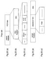
Figures 19(a) to 19(c) schematically show formats of TS
packets. The TS packets have numbers inherent in packets,
respectively, which are called PIDs (packet identifiers).
For example, the same PES packet has the sane PID. The TS packets
comprise a header, an adaptation field or data part
subsequent to the header as shown in figure 19(b). The PID
of the TS packet is given as a part of the header as shown
in figure 19(c).
In figures 19(a) to 19(c), a data region of the TS
packet may include information as to program selection which
is called PSI (program specific information) other than the
PES. In the PSI, a number of a program and the PID of the TS
packet including video data PES, audio data PES and data PES
packets are described. Multiplexed data of a specific
program is decoded and reproduced to obtain original images,
referring to the PSI.
According to the prior art, the PES packet or the TS
packet is produced by adding various information to various
data of video data or audio data, resulting in a TS, which
is recorded and stored or transmitted.
A description is given of a prior art multiplexed data
reproducing apparatus wherein data multiplexed in the MPEG2
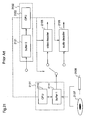
data multiplexing system is decoded/reproduced. Figure 21
is a block diagram illustrating the prior art reproducing
apparatus. In the figure, a separating means 2101 is for
separating required portion from multiplexed data for each
packet, comprising a first buffer 2111 and a CPU 2112. A
control means 2102 is for controlling of decoding,
comprising a second buffer 2121 and a CPU 2122. A video
decoder 2105 is for decoding video data. An audio decoder
2106 is for decoding audio data.
Figure 22 is a flowchart illustrating a procedure of
control of the control means 2102. A description is given
of an operation of the prior art MPEG2 multiplexed data
reproducing apparatus constructed above.
As shown in figure 21, multiplexed data is input from a
recording medium 2107 or a transmission medium 2108 to the
buffer 2111, the multiplexed data being stored temporarily
therein. The CPU 2112 extracts video PES and audio PES
corresponding to a desired program number based on a
correspondence between a program and a PID which is obtained
from separated/extracted PSI and outputs the video PES and the audio
PES to a video decoder 2105 and an audio decoder 2106,
respectively.
Each decoder performs decoding processing, directed by
the control means 2102. Figure 22 is a flowchart
illustrating a processing procedure of control of the
control means 2102. A description is given of control
procedure of the control means 2102, following a flow in
figure 22. In step 2201, an STC (system time clock) is
obtained as a time base of the decoding apparatus on the
basis of PCR in the TS packet. By obtaining the STC, a time
base of reproducing apparatus matches a time base of an
encoding apparatus. In step 2202, the video decoder 2105
performs decoding to obtain PTS or DTS. Similarly in step
2203, the audio decoder 2106 performs decoding to obtain
DTS.
In step 2204, it is decided that whether the video
decoder 2105 has started decoding or not and whether the PTS
or the DTS which is obtained in step 2202 matches the STC.
When it is decided that the video decoder 2105 has not
started processing and the PTS or the DTS matches the STC,
step 2206 is performed and the video decoder 2105 starts
decoding. Similarly, in step 2205, it is decided whether
the audio decoder 2106 has started decoding or not and
whether the DTS which is obtained in step 2203 matches the
STC or not. When it is decided that the audio decoder 2106
has not started processing and the DTS matches the STC, step
2207 is performed and the audio decoder 2106 starts
decoding. For decision in step 2204, both PTS and DTS are
not used for comparison. The video decoder 2105 and the
audio decoder 2106 have the same time base under the control
described above, so that synchronization and reproduction
are performed, to be displayed.
A description is given of a prior art multiplexed data
reproducing apparatus according to the standard MPEG2
(ISO/IEC 13818-1, "Information technology-Generic coding of
moving pictures and associated audio information: Systems",
1996.4), in terms of use of clock information.
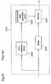
Figure 23 is a block diagram illustrating the prior art
data reproducing apparatus according to MPEG2. In the
figure, a decoder 2301 is for decoding and reproducing
compressed video data and audio data. A buffer 2302 is for
storing the data temporarily. A clock extraction circuit
2303 is for extracting clock information from input
multiplexed data. A synchronization clock generation
circuit 2304 is for generating synchronization clock signals
on the basis of input clock information. For example, a PLL
(phase locked loop) circuit under a feedback control may be
employed to generate the synchronization clock signals.
Figure 24 illustrates multiplexed digital data as an input
of the data reproducing apparatus. In the figure, reference
characters d11 to d15 designate compressed digital video
data, reference characters d21 to d22 designate compressed
digital audio data, and reference characters c1 and c2
designate clock information, which have been multiplexed.
Clock information includes a value of clocks at 27 MHs of
the apparatus which is counted using set modulo.
A description is given of the prior art data
reproducing apparatus constructed above. When multiplexed
data is input to the apparatus, the clock extraction circuit
2303 separates/extracts the clock information c1 and c2 and
outputs the extracted c1 and c2 shown in figure 24 to the
synchronization clock generation circuit 2304. Video data
d11 to d15 and audio data d21 to d25 in figure 24 are output
to the buffer 2302 and stored therein temporarily for
decoding.
The synchronization clock generation circuit 2304
generates synchronized clock signals on the basis of input
clock information and outputs the synchronized clock signals
to the decoder 2301. The decoder 2301 decodes video data
and audio data stored temporarily in the buffer 2302 using
the synchronized clock signals, resulting in an output of
the apparatus.
Figure 25 is a diagram for explaining transition of a
buffer in the case of decoding video data, where a lateral
axis represents time and a longitudinal axis represents a
buffer occupation. This figure does not illustrate
transition itself of the buffer 2302 in figure 23 but
illustrates transition of a virtual buffer as a model.
Namely, a transition of a buffer defined as a virtual buffer
model in MPEG2 is shown in this figure. It is assumed that
data is input to the buffer at a given transfer rate through
a transmission path and a decoder performs decoding in a
short time every 1/30 second, i.e., for each frame.
Therefore, data required for decoding of each frame is
fetched from the buffer every 1/30 second. In encoding
according to MPEG2, buffer status of a decoder is reproduced
virtually by using a virtual buffer model and data is sent
under control so that overflow and underflow may not occur
in the buffer.
Reference numeral 251 in figure 25 indicates a normal
status. In the normal status, clocks of the reproducing
apparatus is synchronized with clocks of the encoding
apparatus, so that processing is performed with no overflow
or underflow mentioned later. Reference numeral 252
indicates a status in which speed of the clocks of the
encoding apparatus is somewhat higher than that of the
reproducing apparatus. In this case, since the encoding
apparatus operates at high speed, the reproducing apparatus
is in a status in which a transfer rate of input becomes
higher. As a result, data to be input is more than data to
be fetched as represented by 252 and accordingly buffer
occupation of 252 becomes significantly higher than that of
251, resulting in overflow above buffer maximum at one point
as shown by a and loss of data. On the other hand, in the
case of higher speed clocks of the reproducing apparatus, a
transfer rate is practically lower. As a result, as
represented by 253, occupation becomes lower gradually,
resulting in underflow below lower limit as represented by b
in the figure which causes discontinuity of reproduction of
motion pictures. Thus, when clocks of the encoding
apparatus are different from clocks of reproducing
apparatus, speed of transmitted data and speed of decoded
data are varied from each other, causing overflow or
underflow in the buffer of the reproducing apparatus.
For the reason mentioned above, clock information is
multiplexed into multiplexed data as shown in figure 24 and
synchronized clocks obtained on the basis of the clock
information are used in the reproducing apparatus, thereby
the problem previously mentioned is avoided.
As concerns image encoding, attention has been paid to
an object encoding method in which components constituting
an image, i.e., a background, characters, moving objects or
the like are handled independently, respectively, and
encoding is performed for each object. In the object
encoding, since encoding is performed for each object,
editing such as replacing specific objects can be performed
with ease.
However, in production of multiplexed data and decoding
and reproduction thereof according to the prior art, the
following problem arises. According to the prior art,
decoding and reproduction can be performed on the basis of
the same time base on the assumption that multiplexed data
is produced in the same encoding apparatus. Therefore, for
the case of performing object encoding, if each object
included in one piece of multiplexed data can be encoded in
the same encoding apparatus and can be processed using the
same time base, decoding and reproduction can be performed
with ease. However, since each object to be edited is not
always encoded by the same encoding apparatus, it does not
always has the same base. In such case, synchronization and
reproduction of objects cannot be performed using the prior
art method.
For example, when multiplexed two objects are decoded
using clocks synchronized with clocks of one encoding
apparatus, one object can be reproduced with ease and clocks
for the other object has not been synchronized. As a
result, the buffer overflows or underflows, and decoding and
reproduction cannot be performed normally.
SUMMARY OF THE INVENTION
It is an object of the present invention to provide a
method and an apparatus for producing multiplexed data
wherein, for producing multiplexed data on the basis of
digital data resulting from an object encoding, when
respective objects are encoded in different encoding
apparatus, troubles due to lack of synchronization of clocks
in reproduction can be avoided.
It is another object of the present invention to
provide a method and an apparatus for clock conversion
wherein troubles due to lack of synchronization of clocks
are avoided in reproduction of multiplexed data with
different time base.
It is still another object of the present invention to
provide a method and an apparatus for reproducing
multiplexed data wherein troubles due to lack of
synchronization of clocks are avoided in reproduction of
multiplexed data with different time base, thereby smooth
reproduction can be realized.
Other objects and advantages of the invention will
become apparent from the detailed description that follows.
The detailed description and specific embodiments described
are provided only for illustration since various additions
and modifications within the spirit and scope of the
invention will be apparent to those skill in the art from
the detailed description.
According to a first aspect of the present invention, a
multiplexed data producing apparatus which multiplexes N
(integer) pieces of object data in which one of video data,
audio data, and digital data is multiplexed to produce one
piece of multiplexed data comprises a temporal storage means
for temporarily storing the N pieces of object data; a
control means for controlling synchronization of time
information of each object data for each temporarily stored
object data; and a multiplexing means for multiplexing the
processed object data to produce multiplexed data.
Therefore, in the case of encoding objects using their
respective encoding apparatus, it is possible to produce
multiplexed data with no troubles in reproduction due to
lack of synchronization.
According to a second aspect of the present invention,
the multiplexed data producing apparatus according to the
first aspect wherein, the control means extracts time
information of specified object data of the N pieces of
object data, extracts the video data, the audio data, and
the digital data of object data except the specified object
data of the N pieces of object data, produces a reference
clock on the basis of the extracted time information, and
multiplexes the video data, the audio data, and the digital
data which are extracted from object data except the
specified object data using the reference clock to produce
corrected object data.
According to a third aspect of the present invention,
the multiplexed data producing apparatus according to the
first aspect wherein the control means uses time information
of specified object data of the N pieces of object data as a
reference, and performs control so as to produce
synchronization control data including absolute time
information and time precision information on the basis of a
difference between time information of object data except
the specified object data of the N pieces of object data and
the reference time information.
According to a fourth aspect of the present invention,
the multiplexed data producing apparatus according to the
third aspect wherein the control means performs control so
as to produce priority information indicating that the
reference clock is obtained on the basis of time information
of object data of the N pieces of object data in the order
of priorities when the produced multiplexed data is decoded.
According to a fifth aspect of the present invention,
the multiplexed data producing apparatus according to the
first aspect wherein the control means uses time information
of specified object data of the N pieces of object data as a
reference and performs control so as to change a
multiplexing interval of object data except the specified
object data of the N pieces of object data in accordance
with the reference time information.
According to a sixth aspect of the present invention,
the multiplexed data producing apparatus according to the
fifth aspect wherein the control means controls change of
the multiplexing interval by one of inserting null data and
deserting the null data.
According to a seventh aspect of the present invention,
the multiplexing data producing apparatus according to the
first aspect wherein the control means uses time information
of specified object data of the N pieces of object data as a
reference and performs control so as to renew time
information of object data except the specified object data
of the N pieces of object data into the reference time
information.
According to an eighth aspect of the present invention,
the multiplexing data producing apparatus according to the
seventh aspect wherein the control means performs control so
as to add a special reproduction flag for correcting a
difference in time precision between object data except the
specified object data of the N pieces of object data and the
specified object data.
According to a ninth aspect of the present invention,
an encoded data reproducing apparatus which decodes and
reproduces multiplexed data in which one of video data,
audio data, and digital data is multiplexed comprises a
demultiplexing means for extracting required data from the
multiplexed data; a decoding means for decoding the
extracted data; and a control means for controlling the
decoding so that the multiplexed data can be synchronized
and reproduced. Therefore it is possible to produce
multiplexed data with no reproduction troubles.
According to a tenth aspect of the present invention,
an encoded data reproducing apparatus processes multiplexed
data which is produced in the multiplexed data producing
apparatus according to any of the first to tenth aspect,
thereby the multiplexed data which is produced in the
multiplexed data producing apparatus according to the first
aspect can be reproduced with no troubles in reproduction.
According to a 11th aspect of the present invention,
the encoded data reproducing apparatus according to a ninth
aspect wherein the control means performs control so as to
use video data included in specified object data of N pieces
of object data multiplexed into the multiplexed data as a
background of an image to be reproduced, and to use time
information of the specified object data as a reference
clock of the encoded data reproducing apparatus.
According to a 12th aspect of the present invention,
an encoded data reproducing apparatus which decodes and
reproduces multiplexed data in which one of video data,
audio data, and digital data is multiplexed, and inputs
multiplexed data which is produced in the multiplexed data
producing apparatus according to the fourth aspect comprises
a demultiplexing means for extracting required data from the
multiplexed data; a decoding means for decoding the
extracted data; and a control means for controlling the
decoding so that the multiplexed data can be synchronized
and reproduced by setting a reference clock of the encoded
data reproducing apparatus in accordance with the priority.
According to a 13th aspect of the present invention, an
encoded data recording medium which records one piece of
multiplexed data in which N pieces of object data is
multiplexed, each of the N pieces of object data including
one of video data, audio data, and digital data which has
been multiplexed, is for recording multiplexed data in which
time information of the N pieces of object data is
synchronized. Therefore, multiplexed data can be stored
with no troubles in reproduction.
According to a 14th aspect of the present invention, an
encoded data recording medium records multiplexed data which
is produced in the multiplexed data producing apparatus
according to the first aspect in the encoded data recording
medium according to the 13th aspect.
According to a 15th aspect of the present invention, an
encoded data transmission medium which transmits one piece
of multiplexed data in which N pieces of object data is
multiplexed, each of the N pieces of object data including
one of video data, audio data, and digital data which has
been multiplexed, is for transmitting multiplexed data in
which time information of the N pieces of object data is
synchronized. Therefore, multiplexed data with no troubles
in reproduction can be transmitted.
According to a 16th aspect of the present invention, an
encoded data transmission medium which transmits multiplexed
data which is produced in the multiplexed data producing
apparatus according to the first aspect.
According to a 17th aspect of the present invention,
there is provided an encoded data reproducing apparatus for
decoding encoded digital data in which one of video data,
audio data, and text data is compressively encoded, to
reproduce one of video, audio, and text, and the apparatus
comprises: storage means for storing N pieces of encoded
digital data each including clock information of an encoding
apparatus used for the compressive encoding; decoding means
for decoding the encoded digital data; and control means for
controlling the storage means and the decoding means so that
the encoded digital data stored in the storage means are
read out using a clock of this encoded data reproducing
apparatus and then decoded. Therefore, trouble caused by
lack of clock synchronization at reproduction of multiplexed
data having different time bases is avoided, resulting in
satisfactory reproduction.
According to an 18th aspect of the present invention,
there is provided an encoded data reproducing apparatus for
decoding encoded digital data in which one of video data,
audio data, and text data is compressively encoded, to
reproduce one of video, audio, and text, and the apparatus
comprises: storage means for storing N pieces of encoded
digital data each including clock information of an encoding
apparatus used for the compressive encoding, except
specified encoded digital data; decoding means for decoding
the encoded digital data; and control means for controlling
the decoding so that a synchronized clock of this encoded
data reproducing apparatus is generated according to the
clock information included in the specified encoded digital
data, and the encoded digital data stored in the storage
means are read out using a clock of this encoded data
reproducing apparatus. Therefore, trouble caused by lack of
clock synchronization at reproduction of multiplexed data
having different time bases is avoided, resulting in
satisfactory reproduction.
According to a 19th aspect of the present invention,
there is provided an encoded data reproducing apparatus for
decoding encoded digital data in which one of video data,
audio data, and text data is compressively encoded, to
reproduce one of video, audio, and text, and the apparatus
comprises: storage means for storing N pieces of encoded
digital data each including clock information of an encoding
apparatus used for the compressive encoding; and decoding
means for reading the encoded digital data stored in the
storage means using a clock of this encoded data reproducing
apparatus and then decoding the read data. Therefore,
trouble caused by lack of clock synchronization at
reproduction of multiplexed data having different time bases
is avoided, resulting in satisfactory reproduction.
According to a 20th aspect of the present invention,
there is provided a clock conversion apparatus for
converting clock information possessed by encoded digital
data in which one of video data, audio data, and text data
is compressively encoded, and the apparatus comprises:
storage means for storing N pieces of encoded digital data
each including clock information of an encoding apparatus
used for the compressive encoding; and clock conversion
means for renewing the clock information of the encoded
digital data stored in the storage means, using a clock of
this clock conversion apparatus. Therefore, trouble caused
by lack of clock synchronization at reproduction of
multiplexed data having different time bases is avoided.
According to a 21st aspect of the present invention,
there is provided a clock conversion apparatus for
converting clock information possessed by encoded digital
data in which one of video data, audio data, and text data
are compressively encoded, and the apparatus comprises:
storage means for storing N pieces of encoded digital data
each including clock information of an encoding apparatus
used for the compressive encoding; and clock conversion
means for reading the encoded digital data stored in the
storage means using a clock of this clock conversion
apparatus, and deleting the clock information of the encoded
digital data other than specified encoded digital data.
Therefore, trouble caused by lack of clock synchronization
at reproduction of multiplexed data having different time
bases is avoided.
According to a 22nd aspect of the present invention, in
the clock conversion apparatus according to the 20th aspect,
employed as a clock of this clock conversion apparatus is a
clock which is not synchronized with any of the clock
information of the N pieces of encoded digital data.
According to a 23rd aspect of the present invention, in
the clock conversion apparatus according to the 21st aspect,
employed as a clock of this clock conversion apparatus is a
clock which is not synchronized with any of the clock
information of the N pieces of encoded digital data.
According to a 24th aspect of the present invention, in
the clock conversion apparatus according to the 20th aspect,
employed as a clock of this clock conversion apparatus is a
clock which is synchronized with at least one of the clock
information of the N pieces of encoded digital data.
According to a 25th aspect of the present invention, in
the clock conversion apparatus according to the 21st aspect,
employed as a clock of this clock conversion apparatus is a
clock which is synchronized with at least one of the clock
information of the N pieces of encoded digital data.
According to a 26th aspect of the present invention, in
the clock conversion apparatus according to the 20th aspect,
the N pieces of encoded digital data are multiplexed and
then output.
According to a 27th aspect of the present invention, in
the clock conversion apparatus according to the 21st aspect,
the N pieces of encoded digital data are multiplexed and
then output.
According to a 28th aspect of the present invention,
there is provided an encoded data reproducing apparatus for
decoding encoded digital data in which one of video data,
audio data, and text data is compressively encoded, to
reproduce one of video, audio, and text, wherein encoded
digital data processed in the clock conversion apparatus
according to the 20th aspect is employed as the decoding
target, and the same clock is used for the decoding.
Therefore, satisfactory reproduction without trouble is
realized.
According to a 29th aspect of the present invention,
there is provided an encoded data reproducing apparatus for
decoding encoded digital data in which one of video data,
audio data, and text data is compressively encoded, to
reproduce one of video, audio, and text, wherein encoded
digital data processed in the clock conversion apparatus
according to the 21st aspect is employed as the decoding
target, and the same clock is used for the decoding.
Therefore, satisfactory reproduction without trouble is
realized.
According to a 30th aspect of the present invention,
there is provided an encoded data recording medium in which
encoded digital data obtained by compressive encoding of one
of video data, audio data, and text data is recorded,
wherein encoded digital data processed in the clock
conversion apparatus according to the 20th aspect is
recorded. Therefore, encoded digital data capable of
avoiding reproduction trouble can be stored and utilized.
According to a 31st aspect of the present invention,
there is provided an encoded data recording medium in which
encoded digital data obtained by compressive encoding of one
of video data, audio data, and text data is recorded,
wherein encoded digital data processed in the clock
conversion apparatus according to the 21st aspect is
recorded. Therefore, encoded digital data capable of
avoiding reproduction trouble can be stored and utilized.
According to a 32nd aspect of the present invention,
there is provided an encoded data transmitting medium in
which encoded digital data obtained by compressive encoding
of one of video data, audio data, and text data is
transmitted, wherein encoded digital data processed in the
clock conversion apparatus according to the 20th aspect is
transmitted. Therefore, encoded digital data capable of
avoiding reproduction trouble can be transmitted and
utilized.
According to a 33rd aspect of the present invention,
there is provided an encoded data transmitting medium in
which encoded digital data obtained by compressive encoding
of one of video data, audio data, and text data is
transmitted, wherein encoded digital data processed in the
clock conversion apparatus according to the 21st aspect is
transmitted. Therefore, encoded digital data capable of
avoiding reproduction trouble can be transmitted and
utilized.
According to a 34th aspect of the present invention,
a method of producing multiplexed data for multiplexing N
(N: integer) pieces of object data in which one of video
data, audio data, and digital data is multiplexed, to
produce one piece of multiplexed data comprises temporarily
storing the N pieces of object data; synchronizing time
information of each object data for each temporarily stored
object data; and multiplexing the processed object data to
produce multiplexed data. Therefore, in the case of
encoding objects using their respective encoding apparatus,
it is possible to produce multiplexed data with no troubles
in reproduction due to lack of synchronization.
According to a 35th aspect of the present invention,
the method of producing multiplexed data according to the
34th aspect further comprises extracting time information of
specified object data of the N pieces of object data;
extracting the video data, the audio data, and the digital
data of object data except the specified object data of the
N pieces of object data; producing a reference clock on the
basis of the extracted time information; and multiplexing
the video data, the audio data, and the digital data which
are extracted from object data except the specified object
data to produce corrected object data using the reference
clock.
According to a 36th aspect of the present invention,
the method of producing multiplexed data according to the
34th aspect further comprises using time information of
specified object data of the N pieces of object data as a
reference and producing synchronization control data
including absolute time information and time precision
information on the basis of a difference between time
information of object data except the specified object data
of the N pieces of object data and the reference time
information.
According to a 37th aspect of the present invention,
the method of producing multiplexed data according to the
36th aspect further comprising producing priority
information indicating that the reference clock is obtained
on the basis of time information of object data of the N
pieces of object data in the order of priorities when the
produced multiplexed data is decoded.
According to a 38th aspect of the present invention,
the method of producing multiplexed data according to the
34th aspect further comprises using time information of
specified object data of the N pieces of object data as a
reference and changing a multiplexing interval of object
data except the specified object data of the N pieces of
object data in accordance with the reference time
information.
According to a 39th aspect of the present invention,
the method of producing multiplexed data according to the
38th aspect wherein the multiplexing interval is changed by
one of inserting null data and deserting null data.
According to a 40th aspect of the present invention,
the method of producing multiplexed data according to the
34th aspect further comprises using time information of
specified object data of the N pieces of object data and
renewing time information of object data except the
specified object data of the N pieces of object data into
the reference time information.
According to a 41st aspect of the present invention,
the method of producing multiplexed data according to the
40th aspect wherein a special reproduction flag for
correcting a difference in time precision between object
data except the specified object data of the N pieces of
object data and the specified object data is added to the
object data except the specified object data.
According to a 42nd aspect of the present invention,
there is provided an encoded data reproducing method for
decoding encoded digital data in which one of video data,
audio data, and text data is compressively encoded, to
reproduce one of video, audio, and text, and the method
comprises: storing N pieces of encoded digital data each
including clock information of an encoding apparatus used
for the compressive encoding; and controlling the decoding
so that the encoded digital data stored are read out using a
clock of this encoded data reproducing method and then
decoded. Therefore, trouble caused by lack of clock
synchronization at reproduction of multiplexed data having
different time bases is avoided, resulting in satisfactory
reproduction.
According to a 43rd aspect of the present invention,
there is provided an encoded data reproducing method for
decoding encoded digital data in which one of video data,
audio data, and text data is compressively encoded, to
reproduce one of video, audio, and text, and the method
comprises: storing N pieces of encoded digital data each
including clock information of an encoding apparatus used
for the compressive encoding, except specified encoded
digital data; generating a synchronized clock of this
encoded data reproducing method according to the clock
information included in the specified encoded digital data;
and reading the stored encoded digital data using the clock
of this encoded data reproducing method and then decoding
the data. Therefore, trouble caused by lack of clock
synchronization at reproduction of multiplexed data having
different time bases is avoided, resulting in satisfactory
reproduction.
According to a 44th aspect of the present invention,
there is provided an encoded data reproducing method for
decoding encoded digital data in which one of video data,
audio data, and text data is compressively encoded, to
reproduce one of video, audio, and text, and the method
comprises: storing N pieces of encoded digital data each
including clock information of an encoding apparatus used
for the compressive encoding; and reading the stored encoded
digital data using a clock of this encoded data reproducing
method and then decoding the data. Therefore, trouble
caused by lack of clock synchronization at reproduction of
multiplexed data having different time bases is avoided,
resulting in satisfactory reproduction.
According to a 45th aspect of the present invention,
there is provided a clock conversion method for converting
clock information possessed by encoded digital data in which
one of video data, audio data, and text data is
compressively encoded, and the method comprises: storing N
pieces of encoded digital data each including clock
information of an encoding apparatus used for the
compressive encoding; and renewing the clock information of
the stored encoded digital data using a clock of this clock
conversion method. Therefore, trouble caused by lack of
clock synchronization at reproduction of multiplexed data
having different time bases is avoided.
According to a 46th aspect of the present invention,
there is provided a clock conversion method for converting
clock information possessed by encoded digital data in which
one of video data, audio data, and text data are
compressively encoded, and the method comprises: storing N
pieces of encoded digital data each including clock
information of an encoding method used for the compressive
encoding; and reading the stored encoded digital data using
a clock of this clock conversion method, and deleting the
clock information of the encoded digital data other than
specified encoded digital data. Therefore, trouble caused
by lack of clock synchronization at reproduction of
multiplexed data having different time bases is avoided.
According to a 47th aspect of the present invention, in
the clock conversion method according to the 45th aspect,
employed as a clock of this clock conversion method is a
clock which is not synchronized with any of the clock
information of the N pieces of encoded digital data.
According to a 48th aspect of the present invention, in
the clock conversion method according to the 46th aspect,
employed as a clock of this clock conversion method is a
clock which is not synchronized with any of the clock
information of the N pieces of encoded digital data.
According to a 49th aspect of the present invention, in
the clock conversion method according to the 45th aspect,
employed as a clock of this clock conversion method is a
clock which is synchronized with at least one of the clock
information of the N pieces of encoded digital data.
According to a 50th aspect of the present invention, in
the clock conversion method according to the 46th aspect,
employed as a clock of this clock conversion method is a
clock which is synchronized with at least one of the clock
information of the N pieces of encoded digital data.
According to a 51st aspect of the present invention, in
the clock conversion method according to the 45th aspect,
the N pieces of encoded digital data are multiplexed and
then output.
According to a 52nd aspect of the present invention, in
the clock conversion method according to the 46th aspect,
the N pieces of encoded digital data are multiplexed and
then output.
According to a 53rd aspect of the present invention,
there is provided an encoded data reproducing method for
decoding encoded digital data in which one of video data,
audio data, and text data is compressively encoded, to
reproduce one of video, audio, and text, wherein encoded
digital data processed in the clock conversion method
according to the 45th aspect is employed as the decoding
target, and the same clock is used for the decoding.
Therefore, satisfactory reproduction without trouble is
realized.
According to a 54th aspect of the present invention,
there is provided an encoded data reproducing method for
decoding encoded digital data in which one of video data,
audio data, and text data is compressively encoded, to
reproduce one of video, audio, and text, wherein encoded
digital data processed in the clock conversion method
according to the 46th aspect is employed as the decoding
target, and the same clock is used for the decoding.
Therefore, satisfactory reproduction without trouble is
realized.
BRIEF DESCRIPTION OF THE DRAWINGS
Figure 1 is a block diagram illustrating a multiplexed
data producing apparatus according to first to fourth
embodiments of the present invention.
Figure 2 is a diagram for explaining object encoding.
Figure 3 is a flowchart illustrating processing
procedure of producing multiplexed data according to the
first embodiment.
Figure 4 is a block diagram illustrating the
multiplexed data reproducing apparatus according to the
first embodiment.
Figure 5 is a flowchart illustrating a processing
procedure of demultiplexing of the multiplexed data
reproducing apparatus according to the first embodiment.
Figure 6 is a flowchart illustrating a processing
procedure of decoding control of the multiplexed data
reproducing apparatus according to the first embodiment.
Figure 7 is a flow chart illustrating a processing
procedure of producing multiplexed data according to a
second embodiment of the present invention.
Figure 8(a) to 8(c) are diagrams for explaining
production of multiplexed data according to a third
embodiment of the present invention.
Figure 9(a) to 9(e) are diagrams for explaining
production of multiplexed data according to a fourth
embodiment of the present invention.
Figure 10 is a block diagram illustrating an encoded
data reproducing apparatus according to a fifth embodiment
of the present invention.
Figure 11 is a diagram for explaining input encoded
data (multiplexed data) according to the fifth embodiment.
Figure 12 is a flowchart illustrating a processing
procedure of reproducing encoded data according to the fifth
embodiment.
Figure 13 is a block diagram illustrating an encoded
data reproducing apparatus according to a sixth embodiment
of the present invention.
Figure 14 is a block diagram illustrating a clock
conversion apparatus according to a seventh embodiment of
the present invention.
Figure 15 is a flowchart illustrating a processing
procedure of clock conversion according to the seventh
embodiment.
Figure 16(a) to 16(e) are diagrams for explaining clock
conversion according to the seventh embodiment.
Figure 17 is a block diagram illustrating a clock
conversion apparatus according to an eighth embodiment of
the present invention.
Figure 18 is a block diagram illustrating an encoded
data reproducing apparatus according to a ninth embodiment
of the present invention.
Figure 19(a) to 19(c) are diagrams for explaining
transport streams used in MPEG2 data multiplexing method
according to the prior art.
Figure 20(a) to 20(e) are diagrams for explaining
packets employed in MPEG2 data multiplexing method according
to the prior art.
Figure 21 is a block diagram illustrating a multiplexed
data reproducing apparatus according to the prior art.
Figure 22 is a flowchart illustrating a processing
procedure in the multiplexed data reproducing apparatus
according to the prior art.
Figure 23 is a block diagram illustrating an encoded
data reproducing apparatus according to the prior art.
Figure 24 is a diagram for explaining input encoded
data (multiplexed data) to be processed by the encoded data
reproducing apparatus.
Figure 25 is a diagram illustrating transition of a
buffer in an encoded data reproducing apparatus according to
the prior art.
DETAILED DESCRIPTION OF THE PREFERRED EMBODIMENTS
[Embodiment 1]
A multiplexed data producing apparatus according to a
first embodiment of the present invention produces
multiplexed data which can be synchronized and reproduced,
by using a time base of a specified object as a time base of
another object, thereby using plural pieces of object data
of different time base.
The multiplexed data reproducing apparatus according to
the first embodiment reproduces the multiplexed data.
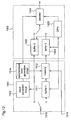
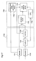
Figure 1 is a block diagram illustrating the
multiplexed data producing apparatus according to the first
embodiment of the present invention. In the figure, a first
buffering means 11 is for temporarily storing first object
data. A second buffering means 12 is for temporarily
storing second object data. A control means 13 is for
controlling processing of object data stored temporarily.
A third buffering means 14 is for processing object data. A
multiplexing means 15 is for producing multiplexed data from
processed object data.
Figure 2 illustrates object encoding and object data.
In the object encoding method, encoding is performed for
each object as shown in figure 2. A target to be encoded in
figure 2 is an image 23 of a series of video data including
objects 21 and 22. The object 21 includes a background 211,
a character 212, an audio 213 and a table 214. The object
22 includes a background 221, a car body 222, wheels 223 and
224, a car audio 225 and character information 226.
Minimum units of objects, namely, 211, 212, 213, 214, 221,
222, 223, 224, 225, and 226 are compressed and encoded,
respectively.
In some cases, objects of high independence such as
objects 21 and 22 constituting one target to be encoded (23)
are encoded by different encoding apparatus. In that case,
reference clocks of objects do not always match from each
other. The reference clock includes an absolute time
indicating a specific time and precision in clock which
clocks the absolute time. It is possible to set a number of
objects arbitrarily. Assume that N=2, that is, two objects
are multiplexed herein.
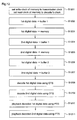
Figure 3 is a flowchart illustrating a processing
procedure under control of the control means 13. A
description is given of an operation of the multiplexed data
producing apparatus according to the first embodiment with
reference figure 3. Assume that two pieces of object data
includes "O1" and "02", respectively, which are obtained
using respective time bases and reference clocks thereof are
varied from each other. Also, assume that they have their
respective time information. Time information includes
decoding time stamp (hereinafter referred to as DTS) as time
information as to decoding for synchronizing and reproducing
video and audio, presentation time stamp (hereinafter
referred to as PTS) as time information for display, and
program clock reference (hereinafter referred to as PCR) as
information as to time in the case of encoding video data or
audio data, which have common time base.
In step 31 in figure 3, the first object data "01" is
input to the apparatus and stored temporarily in the first
buffering means 11. Subsequently in step 32, time
information t1 including PCR, PTS and DTS is extracted from
the temporarily stored object data "01". In step 33,
reference clocks bsclkl is obtained on the basis of the time
information t1.
In step 34, the second object data "02" is input to the
apparatus and stored temporarily in the second buffering
means 12 as in step 31. In step 35, data part D2 except
time information is extracted from the temporarily stored
data "02". In step 36, the control means 13 multiplexes the
data part D2 of the object data "02" obtained in step 35 and
the reference clocks bsclkl obtained in step 33, thereby
producing data "O'2" of the same reference clock as the
object data "O1" and outputting the data "O'2" to a third
buffering means 14.
In step 37, the multiplexing means 15 obtains "O1" from
the first buffering means 11 and "0'2" from the third
buffering means 14 to produce multiplexed data from "01" and
"O'2" and outputs the multiplexed data as an output of the
multiplexed data producing apparatus according to the first
embodiment. The multiplexed data includes two pieces of
object data of the same reference clock.
A description is given of the multiplexed data
reproducing apparatus according to the first embodiment
which decodes and reproduces thus produced multiplexed data.
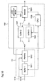
Figure 4 is a block diagram illustrating the multiplexed
data reproducing apparatus according to the first
embodiment. In the figure, a demultiplexing means 41
including a first buffer 411 and CPU 412 is for separating
and extracting required data from input multiplexed data. A
control means 44 including a second buffer 441 and CPU 442
is for controlling decoding of video data, audio data or the
like. A first video decoder 45 and a second video decoder
46 are for decoding encoded video data. A first audio
decoder 47 and a second audio decoder 48 are for decoding
encoded audio data. Figure 5 is a flow chart illustrating a
processing procedure of the demultiplexing means 41 and
figure 6 is a flowchart illustrating a processing procedure
of decoding under control of the control means 46.
A description is given of an operation of the
multiplexed data reproducing apparatus according to the
first embodiment with reference to figure 4, and
simultaneously following flow in figure 5 and figure 6.
In step 51 in figure 5, thus produced multiplexed data is
input to the reproducing apparatus according to the first
embodiment through the recording medium 42 or the
transmission medium 43 and stored temporarily in the first
buffer 411. In step 52, PSI is extracted from the
temporarily multiplexed data. This makes it possible to
find a correspondence between a program and PID of various
data and obtain required data of a desired program.
In step 53, in the demultiplexing means 41, a packet
including PCR, video data and audio data for the desired
program is fetched. The fetched packet is output to the
control means 44 or one of the decoders 45 to 48 in steps
subsequent to step 54. In step 54, PCR is extracted and
output to the control means 44, to be used for control of
decoding.
In step 55, video data and audio data of the object
data "O1" are output to the first video decoder 45 and the
first audio decoder 47, respectively. Similarly in step 56,
video data and audio data of the object data "O2" are output
to the second video decoder 46 and the second audio decoder
48, respectively. Only video data and audio data are handled
herein. In case where multiplexed data includes digital
data except video and audio data, the digital data is output
to the control means 44 and processed therein.
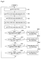
A description is given of decoding each data under
control of the control means 44, following a flow in figure
6. In step 61, the control means 44 obtains system time
information (hereinafter STC) as a time base of the data
reproducing apparatus on the basis of the obtained PCR. In
step 62, the control means 44 controls the first video
decoder 45 and obtains PTS or DTS from the video
data of "O1". Similarly in step 63, the control means 44
controls the first audio decoder 47 and obtains DTS from
audio data of "O1". Steps 64 and 65 are performed for "O2"
as in steps 62 and 63. As a result, decoding in steps
subsequent to steps 661 can be controlled.
In step 661, the control means 44 decides whether a
video decoder for "01", i.e., the first video decoder 45 has
started decoding of video data or not. In addition, the
control means 44 decides whether PTS or DTS obtained in step
62 matches STC obtained in step 61 or not. When it is
decided that the first video decoder 45 has not started
processing of video data and PTS or DTS matches STC, step
662 is performed and the first video decoder 45 starts
decoding of video data of input "O1".
In step 671, the control means 44 decides whether an
audio decoder for "01", i.e., the first audio decoder 47 has
started decoding of audio data or not. In addition the
control means 44 decides whether DTS obtained in step 63
matches STC obtained in step 61. When it is decided that
the first audio decoder 47 has not started processing of
audio data and DTS matches STC, step 672 is performed and
the first audio decoder 47 starts decoding of audio data of
input "01".
Decision processing in step 681 and 691 are performed
as in steps 661 and 671. When step 682 or step 692 is
performed on the basis of the decision result in these
steps, decoding of the video data or audio data of "O2" is
started.
Thus, the multiplexed data producing apparatus
according to the first embodiment comprises the first to
third buffering means 11, 12, and 14, the control means 13
and the multiplexing means 15, so that when multiplexed data
is produced from a plurality of objects, a reference clock
of a specified object is obtained and the other objects are
multiplexed on the basis of the reference clock of the
specified object using residual data except time
information. Therefore, one reference clock is employed for
respective reference clocks of objects and multiplexed data
can be produced with objects synchronized.
The multiplexed data reproducing apparatus according to
the first embodiment comprises the demultiplexing means 41,
the control means 44, video and audio decoders 45 to 48, for
comparing time information included in video data or audio
data with the time base of the reproducing apparatus to make
a decision, and then decoding is performed. As a result,
reproduction and display can be performed with
synchronization of objects maintained.
Having thus illustrated only handling of two object
data, multiplexed data can be produced and reproduced for
object data of an arbitrary number.
In addition, processing procedures shown in figures 3,
5, and 6 are only illustrative. For example, in step 661 in
figure 6, "PTS or DTS=STC", i.e., "match or no match" is
employed as a decision condition. Alternatively, "PTS or
DTS ≥ STC" may be employed to perform the same processing.
Further, as concerns specifying an object, for example,
selection can be performed in such a way that object data
including a video used as a background is used as a
reference.
[Embodiment 2]
A multiplexed data producing apparatus according to a
second embodiment of the present invention produces
multiplexed data which can be synchronized and reproduced by
giving synchronization control data.
A construction of the multiplexed data producing
apparatus according to the second embodiments is identical
to that of the apparatus according to the first embodiment.
A description thereof is given with reference to figure 1.
In the producing apparatus according to the second
embodiment, a processing procedure of control of the control
means 13 is different from that of the first embodiment.
Figure 7 is a flow chart illustrating a processing procedure
of the second embodiment.
A description is given of an operation of the
multiplexed data producing apparatus according to the second
embodiment with reference to figure 1 and following a flow
in figure 7. In step 71, object data "O1" is input to the
apparatus and stored temporarily in a first buffering means
11. In step 72, the control means 13 extracts time
information t1 from the temporarily stored "O1". In step
73, the control means 13 obtains a reference clock bsclkl
from t1. Steps 74 to 76 are performed as in steps 71 to 73
and a reference clock bsclk2 is obtained.
As should be appreciated from foregoing description, a
reference clock includes an absolute time and clock
precision. In step 77, the control means 13 computes a
difference in absolute time and a difference in clock
precision between the reference clocks bsclkl and bsclk2.
The difference in absolute time and the difference in clock
precision are output to a third buffering means 14 as
synchronization control data together with data "O2". In
step 78, the multiplexing means 15 multiplexes "01", "02"
and the synchronization control data using bsclkl and
outputs the resulting data as an output of the multiplexed
data producing apparatus according to the second embodiment.
A construction of the multiplexed data reproducing
apparatus according to the second embodiment is identical to
that of the reproducing apparatus according to the first
embodiment. A description is given of the reproducing
apparatus with reference to figure 4. A reproducing
operation of multiplexed data in the reproducing apparatus
according to the second embodiment is different from that of
the apparatus according to the first embodiment in the
following respects and is identical to that in the other
respects.
An operation of the multiplexed data reproducing
apparatus according to the second embodiment is different
from that of the multiplexed data reproducing apparatus
according to the first embodiment in that synchronization
control data is extracted in the demultiplexing means 41 and
output to the control means 44. In the control means 44, a
difference in absolute time and a difference in clock
precision are extracted from the synchronization control
data. The control means 44 executes control so as to offset
decoding timing of each decoder for video data and audio
data of "O2" using the extracted difference in absolute
time. In addition, the control means 44 executes control so
as to correct asynchronization, by computing ratio of
asynchronization of objects with a lapse of reproduction
time on the basis of the difference in clock precision
extracted from the synchronization control data and by
performing special reproduction.
Thus, with the construction of the multiplexed data
producing apparatus according to the second embodiment,
which is identical to that of the first embodiment, the
synchronization control data including the difference in
absolute time and the difference in clock precision between
clocks and multiplexed data including the synchronization
control data is produced on the basis of the reference
clocks of plural pieces of object data for use in
multiplexing. Therefore, preferable synchronization and
reproduction can be performed in the reproducing apparatus
using the synchronization control data. In addition,
control is executed using the synchronization control data
included in the multiplexed data, thereby the multiplexed
data can be synchronized and reproduced with high precision.
Although it is possible to obtain multiplexed data used
in a general reproducing apparatus in producing multiplexed
data according to the first embodiment, the producing
apparatus requires buffers sufficient for processing object
data, causing some burden in multiplexing processing. On
the other hand, in the second embodiment, it is necessary to
execute control using the synchronization control data in
the reproducing apparatus and processing burden to the
producing apparatus is reduced, compared with the producing
apparatus in the first embodiment.
In the second embodiment, since multiplexing is
performed using the reference clock bsclkl of the specified
object data "O1", multiplexed data including only PCR
synchronized with "O1" is produced. In addition to this, it
is possible to produce multiplexed data including PCR of
different reference clocks. In this case, by assigning a
priority to time information of object data to reproduce a
reference clock and performing multiplexing, a reference
clock is obtained and used in accordance with the priority.
As a result, the reproducing apparatus can perform
synchronization and reproduction with no reproduction
troubles.
Furthermore, as in the first embodiment, the apparatus
can handle digital data other than video data and audio
data, and the apparatus may handle an arbitrary number of
pieces of object data although multiplexed data on the basis
of two pieces of object data has been described.
[Embodiment 3]
A multiplexed data producing apparatus according to a
third embodiment of the present invention produces
multiplexed data which can be synchronized and reproduced by
changing a multiplexing interval.
A construction of the multiplexed data producing
apparatus according to the third embodiment is identical to
that of the apparatus according to the first embodiment and
will be described with reference to figure 1. The producing
apparatus according to the third embodiment differs in a
processing procedure of a control means 13 from those of the
first and second embodiments. Figure 8(a) to 8(c) are
diagrams for explaining changing processing of the
multiplexing interval in the third embodiment. A
description is given of an operation of the multiplexed data
producing apparatus according to the third embodiment with
reference to figures 1 and 8(a) to 8(c).
In figure 1, two pieces of object data "O1" and "O2"
with reference clocks varied from each other are input and
stored temporarily in first and second buffering means 11
and 12, respectively. In figure 8(a) to 8(c), assume that
"O1" and "O2" are 81 in (a) and 82 in (b), respectively.
Audio 11 and 21, video 12 and 22, and data 13 and 23 are
digital data such as audio data, video data and character
information, respectively and are to be synchronized and
displayed, respectively. The object data 81 and 82 except
the audio data, video data and digital data are null data,
that is, data with low significance which is not to be
processed.
In the multiplexed data producing apparatus according
to the third embodiment, the control means 13 changes a
multiplexing interval of "O2" using "O1" as a reference and
outputs the changed data to a third buffering means 14. The
multiplexing interval is changed as follows. As shown in
figure 8(c), until the audio data 11 of "O1" as the
reference arrives, data is inserted before Audio 21. As
shown in figure 8(b), video 12 arrives and data before video
22 is deserted. Similarly as shown in figure 8(c), until
data 13 arrives, data is inserted before data 23. As
concerns deserting data, the null data may be deserted.
Also, the null data may be employed as data to be inserted.
In this way, "O2" with a multiplexing interval thereof
changed becomes data "O'2" synchronized with "O1". The
multiplexing means 15 fetches data "O1" from the first
buffering means 11 and data "O'2" with the multiplexing
interval thereof changed from the third buffering means 14,
and multiplexes a difference in absolute time of reference
clocks between "O1" and "O'2" as synchronization control
data, together with "O1" and "O'2" and outputs resulting
data as an output of the multiplexed data producing
apparatus according to the third embodiment.
A construction of a multiplexed data reproducing
apparatus according to the third embodiment is identical to
that of the reproducing apparatus according to the first
embodiment and a description is given with reference to
figure 4. An operation of reproducing multiplexed data in
the reproducing apparatus according to the third embodiment
is identical to those in the apparatus according to the
first and second embodiments except the following respects.
In the reproducing apparatus according to the third
embodiment as in the reproducing apparatus according to the
second embodiment, synchronization control data is output to
the control means 44 from the demultiplexing means 41. The
control means 44 extracts a difference in control time from
the synchronization control data and executes control using
the difference as in the second embodiment. Control using a
difference in clock precision and special reproduction are
dispensed with.
Thus, with the construction of the multiplexed data
producing apparatus according to the third embodiment, which
is identical to that of the apparatus according to the first
embodiment, using a specified object data of plural pieces
of object data for use in multiplexing as a reference, a
multiplexing interval of the other object data is changed to
be synchronized with the specified object data as the
reference, thereby multiplexed data is produced, including
the synchronization control data which includes a difference
in absolute time between clocks. Therefore, it is possible
to perform preferable synchronization and reproduction using
the synchronization control data. In addition, control is
performed using synchronization control data included in
multiplexed data, thereby the multiplexed data can be
synchronized and reproduced.
Using multiplexed data according to the third
embodiment, since there is an effect of an error in changing
the multiplexing interval, precision in synchronization is
somewhat degraded, compared with that in the first or second
embodiment. However, since clock precision is not taken
into account, processing burden to the producing apparatus
and the reproducing apparatus is not significant and
capabilities of the apparatus or setting time information
can provide appropriate synchronization and reproduction.
It should be noted that setting must be performed in view of
possibility of overflow or underflow in buffers of the
reproducing apparatus resulting from changed multiplexing
interval.
In the third embodiment, the multiplexing interval of
"O2" is changed using "O1" as a reference. Alternatively,
the multiplexing interval of "O1" is changed using "O2" as a
reference and the same effects are attained.
In addition, an arbitrary number of pieces of object
data may be processed as in the case of two pieces of object
data as in the first and second embodiments.
[Embodiment 4]
A multiplexed data producing apparatus according to a
fourth embodiment produces multiplexed data which can be
synchronized and reproduced by using renewal of time
information and a wait flag.
A construction of the multiplexed data producing
apparatus according to the fourth embodiment is identical to
that of the apparatus in the first embodiment and a
description thereof is given with reference to figure 1.
The producing apparatus according to the fourth embodiment
differs in a processing procedure of a control means 13
from those in the first to third embodiments. Figure 9(a)
to 9(e) are diagrams for explaining a processing in the
fourth embodiment. A description is given of an operation
of the multiplexed data producing apparatus according to the
fourth embodiment with reference to figure 1 and figures
9(a) to 9(e).
In figure 1, two pieces of object data "O1" and "O2"
with reference clocks varied from each other are input and
stored temporarily in first and second buffering means 11
and 12, respectively. In figure 9(a) to 9(e), assume that
"O1" and "O2" are 91 in (a) and 92 in (b), respectively.
Audio 11 and 21, video 12 and 22, and data 13 and 23 are
digital data such as audio data, video data and character
information, respectively and are to be synchronized and
displayed, respectively. Respective data includes DTS or
PTS shown in figures 9(a) to 9(e).
The control means extracts time information t1 from the
temporarily stored "O1". Then, the control means 13 renews
time information of the temporarily stored "O2" into t1. As
shown in figure 9(b) and 9(c), data 93 is obtained with DTS
and PTS changed. As shown in figure 9(a) and 9(c), an
effect of a difference in precision in reference clocks
between "O1" and "O2" is not eliminated, remaining as an
error in synchronization. Therefore, the control means 13
adds a wait flag for stopping decoding for some time or
delaying an output of decoded data to data 93 for
multiplexing, thereby the data 93 is output to the third
buffering means 14 in figure 1 as the data 94 ("O'2") in
figure 9(d).
The multiplexing means 15 fetches the data "O1" from
the first buffering means 11 and the data "O'2" from the
third buffering means 14 to multiplex the "O1" and the "O'2"
and outputs resulting multiplexed data as an output of the
multiplexed data producing apparatus according to the fourth
embodiment.
A construction of the multiplexed data reproducing
apparatus according to the fourth embodiment is identical to
that of the reproducing apparatus according to the first
embodiment and will be described with reference to figure 4.
An operation of reproducing multiplexed data in the
reproducing apparatus according to the fourth embodiment is
identical to that of the apparatus according to the first
embodiment except the following respects.
The demultiplexing means 41 detects a wait flag of
input data stored temporarily in the buffer 411. Upon
detection of the wait flag, the demultiplexing means 41
outputs detection signals to the control means 44. On
receipt of the detection signals, the control means 44
controls a decoder concerned of decoders 45 to 48 so that
the decoder concerned stops decoding for some time or it
delays outputting decoded data. Reference numeral 95 shown
in figure 9(e) illustrates a reproduction result of data on
the basis of "O2". The wait flag multiplexed into data 94
in figure 9(d) is processed, thereby video 22 and data 23
are output with delay and synchronized with data shown in
figure 9(a).
With the construction of the multiplexed data producing
apparatus according to the fourth embodiment which is
identical to that of the apparatus according to the first
embodiment, a specified object data of plural pieces of
object data for use in multiplexing is used as a reference,
to renew time information of the other object data into time
information of the reference object data, and the wait flag
for delaying decoding is added to correct asynchronization
due to a difference in clock precision, thereby multiplexed
data is produced. Therefore, use of the wait flag in
reproduction allows producing multiplexed data in the
reproducing apparatus which can be synchronized and
reproduced preferably. In addition, control is executed in
accordance with the wait flag, thereby the multiplexed data
can be reproduced preferably.
The multiplexed data producing apparatus according to
the fourth embodiment bears burden in processing more than
the apparatus according to the second embodiment, and bears
burden less than the apparatus according to the first
embodiment and can produce multiplexed data which can be
synchronized and reproduced with almost the same precision.
In some cases, since renewal of time information is not
performed with ease when there is a large difference in
encoding condition between plural pieces of object data, the
producing apparatus is suitable for the case of handling
object data under almost the same encoding condition.
In the fourth embodiment, the wait flag for delaying
processing is employed. Alternatively, for example, a skip
flag indicating that a processing is not to be performed may
be employed as a special reproduction flag which instructs
special processing in reproduction. In this case, the same
effects are attained.
[Embodiment 5]
An encoded data reproducing apparatus according to a
fifth embodiment of the present invention corrects
asynchronization by temporarily storing data to be decoded
in a memory.
Figure 10 is a block diagram illustrating the structure
of the encoded data reproducing apparatus according to the
fifth embodiment. In the figure, reference numeral 101
designates a storage unit comprising a first buffer 1011 and
a memory 1012. The first buffer 1011 temporarily stores
input multiplexed data. The memory 1012 stores data to be
decoded. Reference numeral 102 designates a decoding unit
comprising a clock generation circuit 1021, a second buffer
1022, a third buffer 1023, a decoder 1024, and a CPU
(Central Processing Unit) 25. The clock generation circuit
1021 generates a clock used for decoding. The second buffer
1022 temporarily stores first encoded digital data to be
decoded. The third buffer 1023 temporarily stores second
encoded digital data to be decoded. The decoder 1024
decodes and reproduces compressed image or audio data. The
CPU controls input/output of data and decoding. Further,
reference numeral 1015 designates multiplexed data to be
decoded, and numeral 1016 designates a transmission clock.
Figure 11 is a diagram for explaining the multiplexed
data 1015 input to the apparatus. In figure 11, the
multiplexed data is composed of first encoded digital data
d11 to d15, clock information c11 and c12 of the first
digital data, second encoded digital data d21 to d25, and
clock information c21 and c22 of the second digital data.
It is premised that the first and second digital data are
produced by object encoding, and compressive encoding in
different encoding apparatuses. In order to reproduce the
first and second data accurately, clock information of the
respective reproducing apparatuses is multiplexed as well.
Figure 12 is a flowchart showing the procedure for
decoding the multiplexed data. Hereinafter, the operation
of the encoded data reproducing apparatus according to this
fifth embodiment will be described along the flowchart of
figure 12, with reference to figures 10 and 11.
Initially, in step 1201 of figure 12, write-clock and read-clock used for
writing and reading information into/from the memory 1012 are set. The write clock is set
to the transmission clock 1016 input to the apparatus, and
the read clock is set to a clock synchronized with the
system clock of the decoding unit 102, which system clock is
generated in the clock generation circuit 1021.
In step 1202, the first encoded digital data is input
to the first buffer 1011 and, in step 1203, it is written in
the memory 1012 in accordance with the set write clock. In
steps 1204 and 1205, the second encoded digital data is
processed in the same manner as steps 1202 and 1203, whereby
the second encoded digital data is written in the memory
1012.
In step 1206, according to the set read clock, the
first encoded digital data stored in the memory 1012 is read
out and input to the second buffer 1022. Likewise, in step
1207, the second encoded digital data is input to the third
buffer 1023. In step 1208, the decoder 1024 decodes the
first encoded digital data using DTS (decoding time stamp).
In step 1209, the decoder 1024 decodes the second encoded
digital data using DTS. Further, in step 1210, the decoding
result of the first encoded digital data, i.e., first
decoded data, is represented according to PTS (presentation
time stamp). In step 1211, the decoding result of the
second encoded digital data, i.e., second decoded data, is
represented according to PTS. Since DTS and PTS are usually
described by relative values of reference clock information,
even though the reference clock changes, only rereading is
needed and the decoding is not adversely affected.
In the above-mentioned operation, the clock used for
transmission of data from the memory 1012 to the second and
third buffers 1022 and 1023 is not the clock of the encoding
apparatus, which is extracted from the clock information
multiplexed to the input multiplexed data 1015, but the
clock of the reproducing (decoding) apparatus itself. So,
there is no lag in clocks between the encoding apparatus and
the decoding apparatus, and overflow or underflow of the
buffer does not occur. Since the lag in clocks between the
encoding apparatus and the decoding apparatus, i.e., a
difference in transmission rates between them, is canceled
when writing/reading of data into/from the memory 1012 are
performed according to the respective rates, a sufficient
capacity is required of the memory 1012. However, since the
memory 1012 stores compressed encoded data, the capacity of
the memory 1012 may be by far smaller than the memory
capacity required in the case where a difference in
transmission rates is canceled by a frame memory or the like
after decoding.
As described above, according to the fifth embodiment
of the invention, the encoded data reproducing apparatus is
equipped with the memory 1012, and writing is performed at a
write rate according to the input transmission clock while
readout is performed at a read rate according to the clock
used for decoding in this reproducing apparatus. Therefore,
it is possible to accurately decode multiplexed data
including digital data generated in encoding apparatuses
with different reference clocks, such as object-encoded
data.
Although in this fifth embodiment two kinds of encoded
digital data, i.e., first and second encoded digital data,
are processed, the number of encoded digital data to be
processed is not restricted thereto. The reproducing
apparatus can process three or more kinds of encoded digital
data by adaptively enhancing the apparatus.
[Embodiment 6]
An encoded data reproducing apparatus according to a
sixth embodiment of the present invention corrects
asynchronization by temporarily storing data to be decoded
in a memory, like the fifth embodiment of the invention.
Figure 13 is a block diagram illustrating the structure
of the encoded data reproducing apparatus according to the
sixth embodiment of the invention. In figure 13, a clock
extraction circuit 1313 separates and extracts clock
information from input data, and outputs the extracted clock
information to a synchronized clock generation circuit 1314.
The synchronized clock generation circuit 1314 generates a
clock synchronized with an input clock, i.e., a clock of a
encoding apparatus in which encoded digital data to be input
to the decoding apparatus is produced, by executing PLL
control or the like, as in the prior art apparatus. The
reproducing apparatus according to this sixth embodiment of
the invention is identical to the reproducing apparatus
according to the fifth embodiment except that the storage
unit 1301 includes the clock extraction circuit 1313 and the
synchronized clock generation circuit 1314, and the decoding
unit 1302 includes no clock generation circuit.
Hereinafter, the operation of the encoded data
reproducing apparatus according to this sixth embodiment
will be described with emphasis on the difference from the
apparatus according to the fifth embodiment. Multiplexed
data 1315 input to the apparatus is identical to that
described for the fifth embodiment (figure 11). While in
the fifth embodiment both of the first and second encoded
digital data included in the multiplexed data 1015 are input
to the first buffer 1011 and the memory 1012, in this sixth
embodiment only the second encoded digital data is input to
the first buffer 1311. The first encoded digital data is
not input to the first buffer 1311 and the memory 1312, but
it is directly input to the second buffer 1322.
The clock extraction circuit 1313 extracts clock
information from the first encoded digital data and outputs
the clock information to the synchronized clock generation
circuit 1314. The synchronized clock generating circuit
1314 generates a synchronized clock, and outputs the clock
so that it is set as a clock used for readout from the
memory 1312. Accordingly, the clock used for readout from
the memory is synchronized with the first encoded digital
data.
Writing of the second encoded digital data, which is
stored in the first buffer 1311, into the memory 1312 is
performed according to the input transmission clock 1316,
like the fifth embodiment. However, for readout of data
from the memory 1312, the reproducing apparatus according to
this sixth embodiment uses the synchronized clock generated
in the synchronized clock generation circuit 1314 while the
reproducing apparatus according to the fifth embodiment uses
the clock of decoding performed in the apparatus.
After the second encoded digital data read from the
memory 1312 is input to the third buffer 1323, the same
process steps as described for the fifth embodiment are
carried out, except that the decoder 1324 of this sixth
embodiment uses the synchronized clock generated in the
synchronized clock generating circuit while the decoder 1024
of the fifth embodiment uses the clock generated in the
clock generation circuit included in the decoding unit 1302.
As described above, in the encoded data reproducing
apparatus according to this sixth embodiment, since the
storage unit 1301 is equipped with the clock extracting
circuit 1313 and the synchronized clock generation circuit
1314. The clock extracting circuit 1313 extracts clock
information from the first encoded digital data included in
the input multiplexed data, and the synchronized clock
generation circuit 1314 generates a synchronized clock based
on this clock information, which clock is used for readout
of data from the memory 1312 and decoding by the decoder
1324. The first encoded digital data is decoded using an
adapted clock, and only the second encoded digital data
synchronized with a clock different from the clock for the
first data is stored, through the first buffer 1311, in the
memory 1312. Therefore, a difference in clocks is canceled,
resulting in satisfactory synchronous reproduction.
The reproducing apparatus according to this sixth
embodiment needs both the clock extracting circuit 1313 and
the synchronized clock generation circuit 1314 while the
apparatus according to the fifth embodiment needs only the
clock generation circuit 1021. However, since the memory
1312 processes only one of the first and second digital
data, the capacity of the memory 1312 may be smaller than
the memory capacity required for the fifth embodiment.
While in the sixth embodiment two pieces of encoded
digital data are input to the apparatus, three or more
pieces of digital data may be input as described above for
the fifth embodiment. Also in this case, clock information
is extracted from one of the input digital data.
While in the fifth and sixth embodiments the first and
second encoded digital data are input as multiplexed data,
these data are not necessarily multiplexed data. That is,
the first and second encoded data may be transmitted
separately and decoded simultaneously.
Further, although in the fifth and sixth embodiments
the transmission clock (1016 in figure 10, 1316 in figure
13) is transmitted separately from video or audio data, when
the transmission clock is included in the first or second
encoded digital data, it can be suitably extracted and used.
Furthermore, in the fifth and sixth embodiments, the
decoding unit includes two, first and second, buffers and a
decoder common to these buffers, and data output from these
buffers are decoded in the decoder by time sharing.
However, the second and third buffers may be physically
united, or two decoders may be provided for the first and
second digital data, respectively. Thus, there are various
methods to implement the apparatus.
Moreover, in the fifth and sixth embodiments, the
transmission clocks 1016 and 1316 are different from the
clock generated by the clock generation circuit 1021 (fifth
embodiment) and the clock generated by the synchronized
clock generation circuit 1314 (sixth embodiment),
respectively. However, when synchronous control is possible
like a communication terminal, the transmission clock is
synchronized with the clock generated by the clock
generation circuit.
[Embodiment 7]
A clock conversion apparatus according to a seventh
embodiment of the present invention performs clock
conversion so that encoded data generated in plural encoding
apparatuses can be decoded synchronously.
Figure 14 is a block diagram illustrating the structure
of the clock conversion apparatus according to the seventh
embodiment of the invention. As shown in figure 14, the
clock conversion apparatus comprises a storage unit 1405 and
a clock conversion unit 1406. Coded digital data output
from first and second encoders 1441 and 1442 are input to
the clock conversion apparatus. These encoders are operated
with different clocks.
The storage unit 1405 comprises a first buffer 1451, a
second buffer 1452, and a memory 1453. The first buffer
1451 and the second buffer 1452 temporarily store the first
encoded digital data output from the first encoder 1441 and
the second encoded digital data output from the second
encoder 1442, respectively. The memory 1453 stores one of
the encoded digital data for clock conversion.
The clock conversion unit 1406 comprises a clock
generation circuit 1461, a clock renewal circuit 1463, and a
CPU 1462. The clock generation circuit 1461 generates a
clock. The clock renewal circuit 1463 renews clock
information of the encoded digital data stored in the memory
1453. The CPU 1462 controls transmission of the encoded
digital data to the memory 1453 and renewal of the clock
renewal circuit 1462. Figure 15 is a flowchart showing the
procedure of control by the CPU 1462.
Hereinafter, the operation of the clock conversion
apparatus according to the seventh embodiment will be
described using figures 14 to 16. The first and second
encoders 1441 and 1442 perform encoding in accordance with
respective clocks, and output first and second encoded
digital data including respective clock information.
In step 1501, the first encoded digital data is input
to the first buffer 1451 of the storage unit 1405.
Subsequently, in step 1502, the first encoded digital data
is read from the first buffer 1451 into the memory 1453
according to the transmission clock 1443. In steps 1503 and
1504, the second encoded digital data is processed in the
same manner as steps 1501 and 1502.
In step 1505, the first encoded digital data is read
from the memory 1453 into the clock renewal circuit 1463.
Next, in step 1506, the clock renewal circuit 1463 renews
the clock information of the first encoded digital data
using a clock generated by the clock generation circuit
1461. In step 1507, renewed first encoded digital data is
output from the clock renewal circuit 1463. In steps 1508
to 1510, the second encoded digital data is processed in the
same manner as steps 1505 to 1507. As a result, multiplexed
data on the basis of the clock-renewed first and second
encoded digital data is output from the clock conversion
apparatus according to this seventh embodiment.
The fundamental operation of the clock conversion
apparatus according to this seventh embodiment is similar to
the operation of the encoded data reproducing apparatus
according to the fifth embodiment. That is, also in the
clock conversion apparatus, the first and second encoded
digital data are written in the memory 1453 using the clocks
1443 and 1444, respectively, and both of these data are read
out using the clock generated by the clock generation
circuit 1461, whereby a difference in clocks is canceled.
However, since the clock conversion apparatus receives data
from an encoding apparatus and outputs a stream to a
decoding apparatus, it must output a stream in which correct
clock information is multiplexed. For this purpose, the
above-mentioned renewal of clock is executed in this seventh
embodiment.
The clock renewal process according to this seventh
embodiment will be described in more detail using figures
16(a)-16(e). Figures 16(a)-16(e) show the contents of
encoded digital data including periodical clock information.
The abscissa shows time. Here, it is premised that the
first and second digital data are compressed at the same
transmission rate. The clock information included in the
first digital data and the clock information included in the
second digital data are represented by counter values of
clocks generated in the first encoder 1441 and the second
encoder 1442, respectively. These encoders are operated
with a reference clock set to, for example, 27 MHz, so that
the clock information is counted at a clock of 27 MHz.
However, since there is a little difference in frequencies
between the first encoder and the second encoder, though the
clock information of the first digital data and the clock
information of the second digital data increase equally by
ten at a time as shown in figures 16(a) and 16(b), the clock
timing of the first digital data is different from that of
the second digital data.
Figures 16(c) and 16(d) show the first and second
encoded digital data that have been read from the memory and
subjected to clock renewal. As shown in these figures, the
clocks are aligned between the first digital data and the
second digital data, and the counter values are renewed to
consistent values, so that the first and second digital data
can be processed with the same clock at decoding and
reproduction. Since the clock conversion apparatus outputs
multiplexed data, the output rate is doubled as shown in
figure 16(e), and the counter value changes with the
increase in the output rate.
As described above, according to the seventh embodiment
of the invention, since the clock conversion apparatus is
equipped with the storage unit 1405 and the clock renewal
unit 1406, when plural pieces of data output from plural
encoders of different clocks are input to the apparatus, the
difference in clocks is canceled, and the input data are
output as synchronously reproducible multiplexed data.
Therefore, it is possible to produce encoded digital data
that can be synchronously reproduced even in a reproducing
apparatus having no large memory.
Although in this seventh embodiment two kinds of
encoded digital data, i.e., first and second encoded digital
data, are processed, the number of encoded digital data to
be processed is not restricted thereto. The clock
conversion apparatus can process three or more kinds of
encoded digital data by adaptively enhancing the apparatus.
[Embodiment 8]
A clock conversion apparatus according to an eighth
embodiment of the present invention performs clock
conversion to realize synchronous reproduction of encoded
data which are encoded in plural encoding apparatus.
Figure 17 is a block diagram illustrating the structure
of the clock conversion apparatus according to the eighth
embodiment of the invention. In figure 17, a synchronized
clock generation circuit 1764 generates a synchronized clock
according to a clock supplied from the first encoder 1741.
A multiplexing circuit 1765 produces multiplexed data from
encoded digital data. The clock conversion apparatus
according to this eighth embodiment is identical to the
clock conversion apparatus according to the seventh
embodiment except that the storage unit 1705 includes no
first buffer and the clock conversion unit 1706 includes the
multiplexing circuit 1765 and the synchronized clock
generation circuit 1764 in place of the clock generation
circuit 1461 of the seventh embodiment.
Hereinafter, the operation of the clock conversion
apparatus so constructed will be described with emphasis on
the difference from the apparatus according to the seventh
embodiment. While in the seventh embodiment the first and
second encoded digital data are input through the buffers to
the memory, in this eighth embodiment only the second
encoded digital data is input through the buffer 1752 to the
memory 1753.
In this eighth embodiment, the first encoder 1741
outputs a clock used for processing the first encoded
digital data to the synchronized clock generation circuit
1764, and the synchronized clock generation circuit 1764
generates a synchronized clock according to the clock output
from the first encoder 1741. According to the synchronized
clock, readout of data from the memory 1753 performed and
renewal of clock in the clock renewal circuit 1763 is
performed.
While the first encoded digital data is input to the
multiplexing circuit 1765 and multiplexed as it is, the
second encoded digital data having a clock different from
the clock of the first encoded digital data is input to the
memory 1753, whereby a difference in clocks is canceled.
As described above, the clock conversion apparatus
according to this eighth embodiment is equipped with the
synchronized clock generation circuit 1764 and the
multiplexing circuit 1765, and clock conversion is performed
on the basis of the clock of the first encoded digital data,
so that the first encoded digital data does not need to be
stored. Therefore, as compared with the clock conversion
apparatus according to the seventh embodiment, the same
effects as provided by the seventh embodiment are obtained
with less memory capacity.
Although in the eighth embodiment two pieces of digital
data are input to the apparatus, three or more pieces of
digital data may be input and, also in this case, clock
information is extracted from one of these digital data.
Although in the seventh and eighth embodiments the
reference clock information is renewed, when plural pieces
of clock information are multiplexed and only one of the
clocks is used for clock reproduction, the reference clock
information included in the second digital data may be
abandoned to simplify the clock renewal circuit.
Further, although in the seventh and eighth embodiments
the first and second encoded digital data are output as
multiplexed data, it is not always necessary to multiplex
the first and second data when output, that is, these data
may be transmitted separately.
Moreover, although in the seventh and eighth
embodiments the first and second encoded digital data input
to the clock conversion apparatus are supplied from the
encoders, the supply source of data is not restricted
thereto. For example, the clock conversion apparatus may
receive encoded data stored in recording media, such as
disks, or data stored in servers in network. In other
words, the clock conversion apparatus can be used as a part
of an encoding apparatus, or as a conversion apparatus for
transmitting outputs from plural servers. In the latter
case, the apparatus is disposed in the middle of the
transmission line.
[Embodiment 9]
An encoded data reproducing apparatus according to a
ninth embodiment of the invention performs decoding of
encoded data produced in the clock conversion apparatuses
according to the seventh and eighth embodiments.
Figure 18 is a block diagram illustrating the structure
of the encoded data reproducing apparatus 1809 according to
the ninth embodiment of the invention. In the figure, a
decoder 1891 decodes and reproduces compressed video or
audio data. A second buffer 1892 and a third buffer 1893
temporarily store encoded digital data input to the
apparatus. A clock extraction circuit 1894 extracts clock
information from the input encoded digital data. A
synchronized clock generation circuit 1895 generates a
synchronized clock according to the input clock. Reference
numerals 1896 and 1897 designate a transmission medium and a
recording medium, respectively.
Hereinafter, the operation of the encoded data
reproducing apparatus so constructed will be described.
Multiplexed data or encoded data obtained in the apparatus
according to the seventh or eighth embodiment is supplied
from the transmission medium 1896 or the recording medium
1897 to the reproducing apparatus. Here, assumed that
multiplexed data in which first and second encoded digital
data and synchronized clock information are multiplexed is
input to the reproducing apparatus.
The clock extraction circuit 1894 separates and
extracts the clock information from the multiplexed data and
outputs the clock information to the synchronized clock
generation circuit 1895. The synchronized clock generation
circuit 1895 generates a synchronized clock according to the
clock information and outputs the synchronized clock to the
decoder 1891.
On the other hand, the first and second digital data
are separated from the multiplexed data and respectively
input to the second and third buffers 1892 and 1893 to be
stored temporarily. The decoder 1891 fetches the first or
second encoded digital data from the second buffer 1982 or
the third buffer 1893 according to the synchronized clock
output from the synchronized clock generation circuit 1895,
decodes the data, and outputs the decoded data from the
apparatus. Since the clocks of the first and second encoded
digital data are equalized in the clock conversion apparatus
according to the seventh or eighth embodiment, even though
the above-mentioned decoding is carried out using the same
clock, accurate reproduction is performed without overflow
or underflow of the buffers. Accordingly, the reproducing
apparatus according to this ninth embodiment is simpler in
structure than the reproduction apparatuses according to the
fifth and sixth embodiments.
As described above, according to the ninth embodiment
of the invention, since the encoded data reproducing
apparatus is equipped with the decoder 1891, the buffers
1892 and 1893, the clock extraction circuit 1894, and the
synchronized clock generation circuit 1895, the apparatus
can perform decoding and reproduction well adapted to the
encoded digital data processed in the clock conversion
apparatus according to the seventh and eighth embodiments.
Although in this ninth embodiment multiplexed data is
input to the reproducing apparatus, the input data is not
restricted thereto. For example, two pieces of encoded
digital data which are not multiplexed may be input directly
to the second and third buffers, respectively.
Further, while in this ninth embodiment two kinds of
encoded digital data, i.e., first and second encoded digital
data, are processed, the number of the encoded digital data
to be processed is not restricted thereto. The reproducing
apparatus can process three or more kinds of encoded digital
data by adaptively enhancing the apparatus.
In the above-mentioned fifth to eighth embodiments, a
buffer or plural buffers is/are connected before a memory.
However, such a buffer, which is generally implemented by a
high-speed memory or the like, is not always necessary.
When the memory is a high-speed memory capable of writing
input data in a short time, the buffer can be dispensed
with.
Furthermore, in the aforementioned embodiments, as a
memory included in the storage unit, various kinds of
recording media can be employed, for example, hard disk,
optical disk, tape, and semiconductor memory such as DRAM or
SRAM.
Moreover, in the aforementioned embodiments,
compressively encoded video data and audio data are
processed. However, text data and uncompressed data are
also applicable to the apparatus in which decoding must be
controlled using a clock multiplexed to transmitted data.