Technical Field
The invention relates to an information recording disc
that records video and/or music information.
Background Art
The problem conventional techniques and the invention
try to solve is explained in the order of the following (1)
single board optical disc and (2) two-disc bonded optical
disc.
(1) Single board optical disc
A so-called compact disc (CD) is well known as an
optical disc that records a music signal by performing 44.1
kHz sampling and 16-bit quantization for a music signal
audible band.
On the contrary, for an application in studios and so
on, a music signal is recorded as a sampling frequency of
88.2 to 96 kHz and the number of quantized bits of 20 to
24 for up to an ultrasound band (approximately 20 to 50 kHz
band) exceeding the music signal audible band. However,
an expensive application apparatus is required for this
recording and reproduction.
The art rejecting unimportant audible parts of sampling
and quantized data for a music signal audible band,
compressing irreversibly an original data with one kind of
compression algorithm, and recording and reproducing on a
recording medium the constant amount of information per
apparatus time of music play time, is known.
The art compressing irreversibly an original data by
using a video space correlation, using time correlation,
and rejecting unnecessary visual data in relation to data
of video signal sampling and amplitude quantization, is
also known.
To compress irreversibly data like this, there are
methods for making the amount of video information per
apparatus time constant, and for changing the amount of
video information per apparatus time depending on the video
condition; both arts are known.
In addition, the art recording and reproducing irreversibly
compressed data on an optical disc using the
former method that makes the amount of video information
per apparatus time constant, is known. Further, the art
recording and reproducing on an optical disc irreversibly
compressed data wherein the amount of information per
apparatus time of video play time is changed depending on
a video condition using the latter method for changing the
amount of video information per apparatus time depending
on a video condition, especially the art reproducing with
buffer memory, pickup kick wait (regenerating wait operation),
and search function, are known. To store a large
amount of data efficiently, a hard disc drive (HDD) for use
with a computer may record the data by compressing reversibly,
with a naming such as so-called lossless compression
and so on, and at reading, expand complementarily the data
to be regenerated; this art is known.
Furthermore, the main art of a high-density optical
disc recording video and/or music information at a density
3 to 8 times higher than that of a CD for general consumers,
is known.
The art wherein a first area that is the inner side of
an optical disc is a CD voice signal recording area, and
a second area that is the outer side of the first area is
a video signal recording area for recording at a high
density a analog FM modulated video signal, is called CD-V
(CD-VIDEO) and known.
Still, the disc wherein the first area that is the
inner side of a high-density recording disc has CD recording
density (low-recording density), and the second area
of its outer side has high-recording density, is, for
example, described in Japanese Patent Laid-Open No.
168449/1994 and known. A system is designed such that,
against a low-density disc reading laser wavelength
(780nm), a high-density disc is read with a short wave-length
laser (635nm). At this time, the pit depth of a
disc is determined in relation to 0.25 times reading laser
wavelength. In other words, it is suitable to make the pit
depth of high-density disc shorter than that of a
low-density disc.
Also, even if the pit depth is not defined as a
standard, it is common that a reproducing signal characteristic
with a standardized normal optical pickup is
defined with a range; and the pit depth is defined equivalently
with a range. Further, in general, the mechanical
accuracy is reduced for a low-density disc, and is strictly
defined for a high-density disc.
In relation to music signal recording and reproduction
to an optical disc, improvements in a voice signal frequency
band (i.e. in a sampling frequency) and in its amplitude
axis accuracy (i.e. in the number of quantized bits), are
required.
High-density digital data that is a music signal
having a sampling frequency of 88 to 96 kHz, and the number
of quantized bits of 20 to 24 for up to an ultrasound band
(approximately 20 to 50 kHz band) exceeding a music signal
audible band, has the amount of data per apparatus time 2.5
to 3.3 times larger than that of a basic digital data
locating 44.1 kHz sampling and 16-bit quantization.
When this high-density digital data is recorded and
reproduced on an optical disc like a CD, it is necessary
to offer 2.5- to 3.3-times improvement in storage capacity
per optical disc, in order to equalize play time per
optical disc with that of a CD. The contents of the main
art of a reproducing apparatus reproducing a high-density
optical disc on which this high-density digital data is
recorded, is known as described above.
However, such high-density optical disc cannot be
reproduced with a conventionally available reproducing
apparatus (e.g. CD player). For this reason, music
publishers must publish two kinds of the same music program
source for a CD and a high-density optical disc, i.e.
perform double inventory.
Also, means for concretely solving this double inventory
to make single inventory, has not been disclosed.
(2) Two-disc bonded optical disc
A multilayer optical disc having a plurality of
recording layers by bonding together two optically transparent
substrates on which a convex and recessed shape
information pit and reflective layer are formed, in order
to increase the recording space of an optical disc so as
to read optically information formed on a helical (spiral
or concentric) information track, is disclosed in Japanese
Patent Laid-Open No. 223030/1990 and Japanese Patent No.
27815/1986. One example of a multilayer optical disc
disclosed in these is shown in Fig. 13.
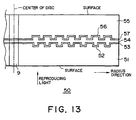
Fig. 13 is a cross-sectional view showing one example
of a conventional multilayer optical disc, and is a diagram
taken along a cutting surface through the center of an
optical disc. The horizontal direction in the same diagram
shows a radius direction of the optical disc; and the
vertical direction shows a thickness direction of the
optical disc.
In an optical disc 50 of Fig. 13, a first recording
layer 52 on which information is recorded by a convex and
recessed shape information pit is provided on a disc
substrate (optically transparent first substrate) 51; and
a first reflective layer 53 is provided on the first
recording layer 52. Likewise, a second recording layer 56
on which information is recorded by a convex and recessed
shape information pit is provided on a disc substrate
(optically transparent second substrate) 55; and a second
reflective layer 57 is provided on the second recording
layer 56.
Each recording layer side of the first substrate 51
and the second substrate 55, is bonded through a bonding
layer 54.
The optical disc 50 has a thin disc substrate for
high-density recording, reducing various optical aberrations
due to disc substrate thickness.
For example, in order that storage space per recording
layer is 4 times the 1.2mm disc substrate thickness of a
conventional CD, the first substrate 51 and the second
substrate 55 have approximately 0.6mm thickness, respectively,
and then the two disc substrates are bonded
together to have recording space 8 times that of a CD.
As shown in Fig. 13, the first recording layer 52 is
formed on the first substrate 51 and is provided in
proximity to the bonding layer 54, while the second
recording layer 56 is formed on the second substrate 55 and
is provided near the bonding layer 54. In other words, two
recording layers are provided in proximity to the thickness
direction center of the optical disc 50.
The reflective rate of the first reflective layer 53
is a low reflective rate (e.g. 30%), while that of the
second reflective layer 57 is a high reflective rate (e.g.
95%). A reproducing laser light is irradiated from the
first substrate 51 side as shown in Fig. 13, and is
gathered on the first recording layer 52 or the second
recording 56 to read information of each recording layer.
Such reproducing apparatus reproducing a high-density
optical disc can naturally reproduce the information on the
first recording layer 52 on the second recording layer 56,
recorded at a high density; and can generally regenerate
a low recording density optical disc like a CD.
To reproduce both of a high-density and low-density
optical discs, the reading optical head in a high-density
optical disc reproducing apparatus has separately the
optical system of a high-density disc optical disc and that
of a low-density optical disc, or adopts a two-focus
hologram-applied optical system; therefore, according to
each optical disc, the size of a laser light spot is
optimized, and the difference in the disc substrate
thickness is corrected.
However, there is a problem that a high-density
optical disc cannot be reproduced by a conventional
low-density optical disc reproducing apparatus.
In a low-density optical disc reproducing apparatus,
this is caused by a too large diameter of a laser light
spot gathered on the recording layer, and the great
difference in thickness between a high-density and
low-density disc substrates.
Ideally, it is desirable that a low-density area A and
a high-density area B coexisting on one information
recording disc, meet standard A based on that the entire
disc surface is low-density area A, and standard B based
on that the entire disc surface is high-density area B,
respectively.
In a disc producing method for recording a phase pit
for mass replicate, the thickness of the photosensitive
agent on an unexposed original disc prepared before
recording, determines a pit depth. It is generally
difficult to change the thickness of the photosensitive
agent on one original disc in a 5% or more step-by-step
manner. In a normal method, the thickness of the photosensitive
agent on one original disc is uniform. When the
low-density area A and the high-density B coexist on one
disc, there is a problem of which one the pit depth is
produced for. The example that the digital signals of the
low-density area A and the high-density area B coexist on
one disc, is described in Japanese Patent Laid-Open No.
168449/1994 mentioned above, but a means for solving the
above problems and this problem has not been covered at
all.
For the problem of when the low-density area A and the
high-density B coexist on one disc, which one the pit depth
(or groove depth) is matched to, the invention combines a
method for defining a pit depth in relation to signal
output, with a method for defining mechanical and optical
accuracies in relation to the disc mechanical accuracy.
In the standard A based on that the entire disc surface is
low-density A and the standard B based on that the entire
disc surface is high-density B, the standard B will
generally be determined chronologically in later years.
The standard B generally uses a short wavelength laser,
having a pit depth shallower than that of the standard A
by an approximately short wavelength.
The standard B defined chronologically in later years
is for high-density recording in consideration of use of
a relatively short wavelength laser and a relatively high
aperture lens; and needs more improvement in disc mechanical
and optical accuracies than those of the standard A.
Considering these requirements and press technology
improvement, the disc mechanical and optical accuracies of
the standard B are determined to be higher than those of
the standard A.
From the above reasons, a low-density and a
high-density optical discs on which the same contents of
program (information) is recorded, are produced and sold
separately, resulting in various inconvenience between
manufacturers and users.
This invention is made in consideration of the above
problem, and aims to offer an information recording disc
having a low-density recording area and high-density
recording area with extremely much recording space.
Disclosure of the Invention
To achieve the above purpose, the information recording
disc of the invention provides a first signal recording
area on which a first data is recorded, and a second signal
recording area that is a signal recording area outside said
first area in the radius direction and wherein a second
data is recorded at a density higher than that of said
first data, and said second data includes the same contents
of information as said first data.
Further the information recording disc of the invention
provides a first signal recording area on which a
first data is recorded, and the second signal recording
area that is a signal recording area outside said first
area in the radius direction and wherein a second data is
recorded at a density higher than that of said first data,
and a third area that is a signal recording area inside
said first area in said radius direction and wherein an
information signal related to said second data is recorded
at the same recording density as that of said second data.
Yet the information recording disc of the invention
provides a signal recording surface having a first signal
recording area and a second signal recording area which is
adjacent to said first signal recording area in the radius
direction, records a signal at a recording density 2 to 10
times that of said first signal recording area, and has the
same signal recording groove depth as that of said first
signal recording area, wherein mechanical and optical
accuracies determined when recording said signal at the
recording density of said second area are applied to the
entire of said signal recording surface.
Still the information recording disc of the invention
wherein a first substrate and a second substrate on which
a regenerating light is irradiated are bonded through a
bonding layer, comprising: a first recording area in
proximity to said bonding layer and formed on the outer
part in the radius direction of said information recording
disc to record information, and a second recording area in
proximity to the surface of said information recording disc
and formed on the inner part of said information recording
disc in the radius direction to record information at a
density lower than that of said first recording layer.
Furthermore the information recording disc of the
invention wherein a first substrate and a second substrate
on which a reproducing light is irradiated are bonded
through a bonding layer, comprising: a first recording area
in proximity to said bonding layer and formed on the outer
part in the radius direction of said information recording
disc to record information, a second recording area in
proximity to said bonding layer and formed on the inner
part in said radius direction to record information, and
a second recording area in proximity to the surface of said
information recording disc and formed between said outer
part and inner part to record information at a density
lower than that of said first and second recording areas.
Brief Description of the Drawings
Fig. 1 is an external view of the information recording
disc of the invention;
Fig. 2 is a diagram for explaining an information area
recorded on the information recording disc in Fig. 1;
Fig. 3 is a spectrum of a music signal;
Fig. 4 is a further external view of the information
recording disc of the invention;
Fig. 5 is a diagram for explaining an information area
recorded on the information recording disc in Fig. 4;
Fig. 6 is a further external view of the information
recording disc of the invention;
Fig. 7 is a diagram showing a signal characteristic of
the information recording disc in Fig. 6;
Fig. 8 is a diagram for explaining an information area
recorded on the information recording disc in Fig. 6;
Fig. 9 is a cross-sectional view of the information
recording disc of the invention;
Fig. 10 is a further cross-sectional view of the
information recording disc of the invention;
Fig. 11 is a further cross-sectional view of the
information recording disc of the invention;
Fig. 12 is an explaining diagram of an unrecordable
part; and
Fig. 13 is a cross-sectional view of a conventional
information recording disc.
Best Embodiments of the Invention
(A) The single board structure of the information
recording medium of the invention is explained along Figs.
1 to 8.
An optical disc 1, an information recording disc of
the invention, provides a signal recording surface 2 having
a first area A and a second area B segmented in the radius
direction, as shown in Fig. 1. Reference numeral 3 is a
center hole.
As shown in Fig. 2, on the information area recorded
in the radius direction of the optical disc 1, "a" is a
radius of the optical disc 1; "b" is a radius from the
center 0 of the center hole 3 to outermost (readout) part
of the signal recording surface 2; "c" is a radius from the
center 0 of the center hole 3 to innermost (readin) part
of the signal recording surface 2; "d" is a radius of the
center hole 3; and "e" is a signal recording area of the
signal recording surface 2. The first area A is composed
of readin area AI, signal recording area AP, and readout
area AO. The second area B is composed of readin area BI,
signal recording area BP, and readout area BO.
[First Embodiment]
The first embodiment of the information recording disc
of the invention is a 120mm diameter audio disc. The disc
thickness (a distance from a disc surface (protective
layer) to a disc signal surface) is 1.2mm.
The first area A located on the inner side starting
reproduction is recorded with a CD format (conforming to
JIS S 8605 standard). The readin area AI of 23 to 25mm
radius, included in the first area A, is recorded by the
CD format.
It is easy to set a status (set a bit showing the kind
of an information recording disc) on this readin area AI
so that a newly formatted reproducing apparatus (player)
can read existence of the second area B, without affecting
a conventional CD player at all. For example, a definition
may be assigned to an unused bit of TOC (Table of Contents)
recorded with a CD subcode, to set a status in which the
second area B exists. After termination of music information
recorded on the signal recording area AP, the defined
length of a readout track (readout area AO) is recorded on
the first area A for termination.
The recording density of music information recorded on
the signal recording area BP of the second area B, is
favorably 2 to 10 times the recording density of the signal
recording area AP. In the embodiment, the recording
density is 4.5 times (3.7 GB recording space on the entire
signal recording surface 2) that of the signal recording
area AP (0.8 GB recording space on the entire signal
recording surface 2). Also the music sources recorded on
the two signal recording areas AP and BP are completely the
same. The music information program recorded on the
signal recording area AP of the first area A, is for up to
a music signal audible band (to approximately 20 kHz), and
becomes data by a CD sampling rate (44.1 kHz sampling
frequency) and the number of quantized bits of 16.
On the other hand, the music information program
recorded on the signal recording area BP of the second area
B, is for up to a music signal ultrasound band above an
audible band (to approximately 50 kHz). 88.2 kHz sampling
frequency and the number of quantized bits of 20 are
relatively higher than the sampling rate and the number of
quantized bits used for recording music information on the
signal recording area AP.
A newly formatted reproducing apparatus (player) is
used for reproduction of the signal recording area BP of
the second area B, combining a unit for increasing regenerating
time. The music information recorded on the signal
recording area BP of the second area B, uses reversibly
compressed music information data (entropy coded). In this
case, on a basis of progressive time apparatus of the music
information, the amount of this music information data
changes.
To reproduce this music information data, the newly
formatted reproducing apparatus uses buffer memory, pickup
kick wait and search functions, and reproducing technology
(the basic explanation of this technology is described in
Japanese Patent Laid-open No. 223669/1989.
Reversible compression of sampled and quantized music
information data is, for example, described in AES-PREPRINT
NO-1549 (document) in November of 1979, in which the
example that 30 to 40 % of music information data sampled
and quantized under a CD condition, can reversibly be
compressed is shown. This reversible compression uses DPCM
technology with a difference from prior data.
The amount of high-quality music information data of
88.2 kHz sampling and 20-bit quantization, is 2.5 times
that of CD music information data of 44.1 kHz sampling and
16-bit quantization.
This applicant's study has determined that, as shown
in Fig. 3, when compressing reversibly this high-quality
music information data, the amplitude in an ultrasound area
D is relatively less than that in an audible band C (a
broken line part shown in Fig. 3); thus the reversible
compression rate is approximately 60%, i.e. the amount of
music information data to be transmitted is approximately
40% of the music information data of 88.2 kHz sampling and
20-bit quantization.
A value estimated by Fig. 3 and the above document in
this application, will be explained such that the reversible
compression rate of the high-quality music information
data of 88.2 kHz sampling and 20-bit quantization, is
approximately 60% i.e. the amount of data to be transmitted
is originally approximately 40%.
Then the embodiment explains the conditions that the
recording and reproducing time of music information (music
program source) recorded on the signal recording area AP
of the first area A, and that on the signal recording area
BP of the second area B, are the same and the longest.
In the embodiment, CD-formatted music information data
is recorded on the signal recording area AP of the first
area A. A CD format can record and reproduce up to
74.7-minute music, if all radiuses of 25 to 58mm of a
program area (i.e. signal recording area e) are used.
Also, on the signal recording area BP of the second area
B, music information data is recorded at a density 4.5
times that of the signal recording area AP.
For this reason, when all radiuses of 25 to 58mm
(signal recording area e) are used for recording music
information data at a density 4.5 times that of the signal
recording area AP, up to 336-minute music can be recorded
and reproduced, as shown by the following equation:
(74.7 minutes * 4.5/2.5)/0.4 = 336 minutes
Assuming that recording and regenerating time of music
information recorded on the signal recording area AP of the
first area A, is X1 minutes; recording and regenerating
time of music information recorded on the signal recording
area BP of the second area B, is X2 minutes; and the area
of a 25 to 58mm radius area (signal recording area e) is
normalized as 1, the normalized area of the first area A
would be:
X1/74.7; and
the normalized area of the second area B would be:
X2/336
Using all areas of 25 to 58mm radius areas, the
normalized areas of two areas A and B are summed to make
the following equation (1):
X1/74.7 + X2/336 = 1
Also the condition that the recording and regenerating
time of music information recorded on the first area A and
that of the second area B are the same, makes the following
equation (2):
X1 = X2
Solve the equations (1) and (2) as simultaneous equations
to obtain:
X1 = 61 minutes X2 = 61 minutes
On the boundary of the first area A and the second
area B needs readout area A0 of the first area, and readin
area BI of the second area. The actual regenerating time
is subtracted from each burden of approximately 1 minute
to obtain:
X1 = 60 minutes X2 = 60 minutes
The above describes the disc that can record and
reproduce 60-minute CD-quality music information on the
signal recording area AP of the first area A on the inner
side of one optical disc 1, and 60-minute high-quality
music information of 88.2 kHz sampling and 20-bit
quantization on the signal recording area BP of the second
area B outside the disc. This disc 1 records the same
music information by CD quality that is standard quality,
and by quality higher than CD quality, i.e. is a single
inventory; therefore it is significant for both music
publishers and users who purchase the discs.
[Second Embodiment]
The second embodiment of the information recording
disc of the invention is a 120mm diameter audio disc. The
disc thickness is 1.2mm.
The second embodiment describes an example that music
information data recorded on the signal recording area BP
of the second area B, has a fixed transfer rate without
reversible compression technology.
The music information data recorded on the signal
recording area AP of the first area A, is recorded by a CD
format like said first embodiment. In the embodiment, the
recording density of music information data recorded on the
signal recording area BP of the second area B, is 4.5 times
that of the music information data recorded on the signal
recording area AP of the first area A. Also the music
information sources recorded on the two signal recording
areas AP and BP are completely the same.
The music information data recorded on the signal
recording area AP of the first area A, is for up to a music
signal audible band (to approximately 20 kHz), and becomes
data by a CD sampling rate (44.1 kHz sampling frequency)
and the number of quantized bits of 16.
On the other hand, the music information data recorded
on the signal recording area BP of the second area B, is
for up to a music signal ultrasound band above an audible
band (to approximately 50 kHz). 88.2 kHz sampling frequency
and the number of quantized bits of 20 are relatively
higher than the sampling rate and the number of quantized
bits used for recording music information on the signal
recording area AP. The method for recording all this music
information data, just as it is, like a CD, has a fixed
transfer rate like the CD.
Then the embodiment explains the conditions that the
recording and reproducing time of music information
recorded on the signal recording area AP of the first area
A, and that on the signal recording area BP of the second
area B, are the same and the longest. In the embodiment,
CD-formatted music information data is recorded on the
signal recording area AP of the first area A. A CD format
can record and regenerate up to 74.7-minute music, if all
radiuses of 25 to 58mm of a program area (i.e. signal
recording area e) are used.
Also, on the signal recording area BP of the second
area B, music information data is recorded at a density 4.5
times that of the signal recording area AP. For this
reason, when all radiuses of 25 to 58mm (signal recording
area e) are used for recording music information data at
a density 4.5 times that of the signal recording area AP,
up to 134.5-minute music can be recorded and regenerated,
as shown by the following equation:
74.7 minutes * 4.5/2.5 = 134.5 minutes
Assuming that recording and reproducing time of music
information recorded on the signal recording area AP of the
first area A, is X1 minutes; recording and reproducing time
of music information recorded on the signal recording area
BP of the second area B, is X2 minutes; and the area of a
25 to 58mm radius area (signal recording area e) is
normalized as 1, the normalized area of the first area A
would be:
X1/74.7; and
the normalized area of the second area B would be:
X2/134.5
Using all areas of 25 to 58 mm radius areas, the
normalized areas of two areas A and B are summed to make
the following equation (3):
X1/74.7 + X2/134.5 = 1
Also the condition that the recording and reproducing
time of music information recorded on the first area A and
that of the second area B are the same, makes the following
equation (4):
X1 = X2
Solve the equations (3) and (4) as simultaneous
equations to obtain:
X1 = 48 minutes X2 = 48 minutes
On the boundary of the first area A and the second
area B needs readout area A0 of the first area, and readin
area BI of the second area. The actual reproducing time
is subtracted from each burden of approximately 1 minute
to obtain:
X1 = 47 minutes X2 = 47 minutes
The above describes the disc that can record and
reproduce 47-minute CD-quality music information on the
signal recording area AP of the first area A on the inner
side of one optical disc 1, and 47-minute high-quality
music information of 88.2 kHz sampling and 20-bit
quantization on the signal recording area BP of the second
area B outside the disc. This disc 1 records the same
music information by CD quality and by quality higher than
CD quality, i.e. is a single inventory; therefore it is
significant for both music publishers and users who
purchase the discs.
Since this disc 1 is not reversibly compressed like
the first embodiment, extended operation for resetting
compression with a regenerating player needed not be
performed.
[Third Embodiment]
The third embodiment of the information recording disc
of the invention is a 120mm diameter video disc. The disc
thickness (a distance from a disc surface (protective
layer) to a disc signal surface) is 1.2mm.
The first area A located on the inner side starting
reproduction is recorded with a CD format (conforming to
JIS S 8605 standard) like said first embodiment. The CD
format contains a format called a video CD which uses a
known MPEG1 standard to record and reproduce an animation
of 352 X 240 pixels. The readin area AI of 23 to 25mm
radius, included in the first area A, is recorded by a
video CD format.
The recording density of video information recorded on
the signal recording area BP of the second area B, is
favorably 2 to 10 times the recording density of the signal
recording area AP. In the embodiment, the recording
density is 4.5 times (3.7 GB recording space on the entire
signal recording surface 2) that of the signal recording
area AP (0.8 GB recording space on the entire signal
recording surface 2). Also the video sources recorded on
the two signal recording areas AP and BP are completely the
same.
The video information program recorded on the signal
recording area BP of the second area B is for moving
picture of 720 X 480 pixels using a known MPEG2 standard.
To record such moving picture, a compression rate is
changed depending on the contents of the moving picture,
and a variable transfer rate system that changes a transfer
rate is used. Since such example is often explained, the
detailed explanation is omitted. It is described in the
embodiment that the recording density for a diameter of
120mm with the MPEG2 standard is 4.5 times that of a CD.
Then, the embodiment explains the conditions that the
recording and reproducing time of video information (video
program source) recorded on the signal recording area AP
of the first area A, and that on the signal recording area
BP2 of the second area B, are the same and the longest.
In the embodiment, video CD-formatted video is recorded
on the signal recording area AP of the first area A.
A video CD format can record and reproduce up to approximately
74-minute video, if all radiuses of 25 to 58mm of
a program area (i.e. signal recording area e) are used.
Also, on the signal recording area BP of the second
area B, video information data is recorded at a density 4.5
times that of the signal recording area AP. For this
reason, when all radiuses of approximately 25 to 58mm
(signal recording area e) are used for recording video
information data at a density 4.5 times that of the signal
recording area AP, an MPEG2 standard video can be recorded
and regenerated for approximately 135 minutes using a
variable transfer rate system.
The time relation of the above example is similar to
the examples of the equations (3) and (4) of the second
embodiment; in the third embodiment, each recording and
reproducing time of the first and second areas is approximately
47 minutes.
The above describes the disc that can record and
reproduce approximately 47-minute CD-quality video information
on the signal recording area AP of the first area A
on the inner side of one optical disc 1, and approximately
47-minute high-quality video information of 88.2 kHz
sampling and 20-bit quantization on the signal recording
area BP of the second area B outside the disc. This disc
1 records the same video information by MPEG1 and MPEG2
qualities i.e. is a single inventory; therefore it is
significant for both publishers and users who purchase the
discs.
Unlike the above optical disc 1 structure, an optical
disc 10 that is another information recording disc of the
invention provides a signal recording surface 20 having the
first area A and the second area B segmented sequentially
in the radius direction from the center hole 3, as shown
in Fig. 4. A third area CC is provided on the inner side
(the center hole 3 side) adjacent to the first area A.
As described later, a readin signal in relation to a
first data recorded on the second area B, that is an
information signal that has the same recording density as
that of the first data, is recorded on the third area CC.
This information signal is a readin signal focusing on a
test signal correcting TOC (contents) information and a
player.
As shown in Fig. 5, on the information area recorded
in the radius direction of the optical disc 10, "a" is a
radius of the optical disc 10; "b" is a radius from the
center o of the center hole 3 to outermost (readout) part
of the signal recording surface 20; "c" is a radius from
the center o of the center hole 3 to innermost (readin)
part of the signal recording surface 20; "d" is a radius
of the center hole 3; and "e" is a signal recording area
of the signal recording surface 20.
The first area A is composed of readin area AI, signal
recording area AP, and readout area AO.
The second area B is composed of readin area BI1,
signal recording area BP, and readout area BO.
The third area CC is readin area BI2 that records a
readin signal having at least data of a readin signal
recorded on the readin area BI1.
In other words, the contents of a readin signal
recorded on the readin area BI1 of the second area B, is
duplicated with the contents of a readin signal recorded
on the third area CC; therefore if the readin signal
recorded on the third area CC is considered main, it is not
inconvenient to, if necessary, change (reduce) the contents
of the readin signal recorded on the readin area BI1 of the
second area B (simplification of the readin signal recorded
on the readin area BI1).
For this changing example, for TOC information wherein
the same data is generally overwritten over and over again
to avoid reading miss, only once TOC information is written
only in the readin signal recorded on the readin area BI1.
As a result, the recording space on the readin area BI1 can
be reduced by this unoverwritten part. Only this reduced
space may be devoted to an increase in the recording space
of the signal recording area BP.
[Forth Embodiment]
Next, the forth embodiment of the information recording
disc of the invention is concretely explained with a
120mm diameter audio disc. The disc thickness (a distance
from disc surface (protective layer) to disc signal
surface) is 1.2mm.
The first area A located on the inner side starting
reproducing is recorded with a CD format (conforming to JIS
S 8605 standard). 23 to 25mm radius readin area AI,
included in the first area A, is recorded by a CD format.
It is easy to set a status on this readin area AI so
that a newly formatted reproducing apparatus (player) can
read existence of the second area B, without affecting a
conventional CD player at all. For example, a definition
may be assigned to an unused bit of TOC (Table of Contents)
recorded with a CD subcode, to set a status in which the
second area B exists.
After termination of music information recorded on the
signal recording area AP, the defined length of a readout
track (readout area AO) is recorded on the first area A for
termination.
The music information program recorded on the signal
recording area AP of the first area A, becomes data by a
CD sampling rate (44.1 kHz sampling frequency) and the
number of quantized bits of 16.
On the other hand, for the music information program
recorded on the signal recording area BP of the second area
B, 88.2 kHz sampling frequency and the number of quantized
bits of 20 are relatively higher than the sampling rate and
the number of quantized bits used for recording music
information on the signal recording area AP.
The recording density of music information recorded on
the signal recording area BP of the second area B, is
favorably 2 to 10 times the recording density of the signal
recording area AP. In the embodiment, the recording
density is 4.5 times (3.7 GB recording space on the entire
signal recording surface 2) that of the signal recording
area AP (0.8 GB recording space on the entire signal
recording surface 2). Also the music sources recorded on
the two signal recording areas AP and BP are completely the
same.
A newly formatted reproducing apparatus (player) is
used for reproduction of the signal recording area BP of
the second area B. To reproduce this music information
data, the newly formatted reproducing apparatus uses buffer
memory, pickup kick wait and search functions, and reproducing
technology (the basic explanation of this technology
is described in Japanese Patent Laid-Open No.
223669/1989).
Since the third area CC and the second area B are
reproduced with a newly formatted reproducing apparatus
(player), this player can determine the side more inner
than a CD format, e.g. the third area CC provided with a
radius of 22.5 to 23mm, as a readin area.
Constructing the disc like the above, a CD player and
a high-density newly formatted player can first reproduce
a readin area corresponding to each recording density,
optimizing a signal reading condition for each player.
Then, an optical disc 100 that is an information
recording disc of the invention, with a different structure
from that of both the above optical discs 1 and 10, is explained.
As mentioned above, a CD as a music information
recording disc is well known in the art. The CD reading
is system-designed so as to use a 780nm laser wavelength,
while a laser with around a 635nm laser light wave has been
practiced in recent years; a high-density disc that reads
with this is under development. Here it is called
high-density CD.
On the other hand, coexisting of a CD recording
density area and a high-density CD recording density area
on one disc, is considered to provide extensive application.
Against the 780nm CD reading laser wavelength, a
high-density CD disc under development that is not of a
public standard, is system-designed so as to read with a
short wavelength laser of around 635nm. In relation to
these, the pit depth of the disc is determined in relation
to 0.25 times a reading laser wavelength. The invention
is explained below by taking a disc wherein many pit rows
form a signal track to record information, as an example.
Although a pit depth is not defined as a standard, a
reproducing signal characteristic with a standard light
pickup to be defined with a standard, is defined with a
range. As a result, the pit depth is determined with a
range. The recording original disc film thickness directly
related to the pit depth is equivalently approximately 100
to 125nm to satisfy a CD standard; and is equivalently
approximately 85 to 105nm for a high-density CD standard.
Since the reproducing signal characteristic related to the
pit depth is not determined only by the recording original
disc film thickness, and is changed by conditions of:
recording development, pressing stamper producing, press
and so on, here "equivalently" is represented with the
value of the recording original disc film thickness,
including these fluctuations.
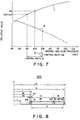
The pit shallower than a standard value increases push
pull tracking output obtained by differentially detecting
the reflective light of a reading laser that is irradiated
on the pit, and decreases a degree of modulation of the
signal. On the contrary, the pit deeper than a standard
value decreases push pull tracking output, and increases
a degree of modulation of the signal. This is shown in
Fig. 7. In the same diagram, I is a degree of modulation
of a CD signal; and II is the push pull tracking output of
a high-density CD signal.
As shown in Fig. 7, when a CD area (low-density
recording area and the first area) and a high-density CD
area (high-density recording area and the second area)
satisfy each standard to coexist on one disc, as shown in
Fig. 6 below, the recording original disc film thickness
range satisfying both standards is equivalently 100 to
105nm, as shown in a control width DD (illustrated in Fig.
7), and is narrow for a producing control width (an
equivalent film thickness control width for production with
disc producing steps).
The reproducing signal characteristic related to the
pit depth is not determined only by the recording original
disc film thickness, and is changed by the conditions of:
recording development, pressing stamper producing, press
and so on, requiring control including these.
In relation to the mechanical accuracy characteristic
of the disc, as a typical item, a disc warp (tilt) characteristic
is 0.6 degrees for a CD standard, and is, e.g.
0.35 degrees for a high-density CD standard. When a CD
area and a high-density CD area coexist on one disc,
applying a mechanical accuracy characteristic standard of
the high-density CD to the CD area can achieved with a
small burden.
By producing a disc to satisfy this standardized in
this way, the tilt for the regenerating signal deterioration
on the CD area is not, as a typical item, 0.6 degrees,
but may be allowed for 0.35 degrees.
The main operation of the invention is that allowance
for CD area reproduction produced by less allowance for the
reproducing signal deterioration that is the above
0.35-degree tilt, is devoted to resolve an equivalent
recording original disc film thickness range of a narrow
producing control width DD of 100 to 105nm. In the
reproducing signal characteristic of the CD area of the
disc of the invention, if a degree of modulation of a CD
standard is slightly changed to, e.g. 0.95 times that of
recording, at a recording density of a CD area, the entire
signal recording surface including a CD area and a
high-density CD area, the equivalent recording original
disc film thickness range satisfying both of the
high-density CD standard and the CD area standard after
change is approximately 95 to 105nm, as shown with a
control width E in Fig. 7, extending sufficiently the
producing control width. Still the equivalent film
thickness is approximately 85 to 105nm for the high-density
CD standard. From curve I in Fig. 7, a degree of modulation
of the CD standard on the CD area the disc of the
invention is approximately 0.7 times that of recording said
entire signal recording surface at a recording density of
the CD area. In terms of the intensity of a signal, a
higher degree of modulation is better, and favorably 0.8
to 0.95 times.
The amount of jitter for reproducing signal deterioration,
when a degree of signal modulation of the CD area of
the disc of the invention is 0.95 times that of the CD
standard, is 0.5% or below. On the other hand, the amount
of jitter for reproducing signal improvement, when a disc
tilt is not 0.6 degrees for the CD standard, but 0.35
degrees, is 1 % or above. Likewise, improvement in such as
shake and eccentricity other than the tilt, is contributed
as improvement in a reproducing signal. Also the described
mechanical accuracy standard, and an optical accuracy such
as a refractive characteristic, are alike.
The above describes the embodiment of the information
recording disc with reasonability shown by the deteriorated
and improved amount of jitter, mechanical and optical
accuracies standards of a disc based on that the entire
disc surface has the density of a high-density CD area, is
applied to all areas of a disc having a CD area and a
high-density CD area of the invention; and the signal
characteristic standard of the CD area of the disc of the
invention is changed, in comparison with that of a standard
based on that the entire disc surface has the density of
the CD area.
The invention is explained with an example of a phase
pit by placing emphasis on understandability. This is
alike to the depth of a groove tracking. The invention can
be applied to a disc with a recording and reproducing
method changing the amount of a reflective light, and a
optical magnet method changing the polarized angle of a
reflective light.
[Fifth Embodiment]
The structure of the information recording disc of the
invention is explained below with Figs. 6 and 8.
The optical disc 100 that is the fifth embodiment of
the information recording disc of the invention, provides
the signal recording surface 200 having the first area A
and the second area B segmented sequentially in the radius
direction from the center hole 3, as shown in Fig. 6. Also
the third area CC is provided on the inner side (the center
hole 3 side) adjacent to the first area A. In the same
diagram, "o" is a disc center; and "a" is a radius. For
example, the diameter of the optical disc 100 is 120mm; the
radius "a" is 60 mm; and the diameter of the center hole
3 is 15mm.
As described later, the third area CC is a readin area
wherein a readin signal in relation to a second data
recorded on the second area B is recorded at the same
recording density as that of the second data. This readin
signal focuses on a test signal correcting TOC information
and a player.
As shown in Fig. 8, on an information area recorded in
the radius direction of the optical disc 100, "b" is a
radius from the center "o" of the center hole 3 of the
optical disc 100 to the outermost (readout) part of the
signal recording surface 200; "c" is a radius from the
center "o" to the innermost (readin) part of the signal
recording surface 200; dd is a radius from the center "o"
to the outermost part of the third area CC; ee is a radius
from the center "o" to the innermost part of the third area
CC; "f" is a radius of the center hole 3; "g" is a signal
recording area width of a signal recording surface 200.
For example, if the radius "a" is 60mm, the radius "b"
is 58.5mm; the radius "c" is 25mm + 0mm to 25mm - 0.2mm;
the radius dd is 23.0mm + 0mm to 23.0mm - 0.2mm; the radius
ee is from the center "o" to max. 22.5mm; and the radius
"f" is 7.5mm.
The first area A is composed of readin area AI that is
the first readin area, signal recording area AP on which
the first data is recorded, and readout area AO.
The second area B is composed of readin area BI1,
signal recording area BP on which the second data is
recorded, and readout area BO that is the second readout
area.
The third area CC is the second readin area, and
readin area BI2 recording a readin signal having at least
data of a readin signal recorded on the readin area BI1 of
the second area B.
In other words, the contents of a readin signal
recorded on the readin area BI1 of the second area B, is
duplicated with the contents of a readin signal recorded
on the third area CC; therefore if the readin signal
recorded on the third area CC is considered main, it is not
inconvenient to, if necessary, change (reduce) the contents
of the readin signal recorded on the readin area BI1 of the
second area B (simplification of the readin signal recorded
on the readin area BI1).
As the example of this change, in general TOC information
records repeatedly the same data with 2mm or more
width in the radius direction to avoid reading miss. The
readin signal recorded on the readin area BI1 writes the
TOC information only with 0.3mm width in the radius
direction. As a result, the recording space on the readin
area BI1 can be reduced. Only this reduced space may be
devoted to an increase in the recording space of the signal
recording area BP.
Then, the information recording disc of the invention
is concretely explained with a 120 mm diameter audio disc.
The disc thickness (a distance from a disc surface (protective
layer) to a disc signal surface) is 1.2mm. The first
area A and the second area B have the same pit depth.
The first area A located on the inner side starting
reproduction is recorded with a CD format (conforming to
JIS S 8605 standard). The readin area AI of 23 to 25mm
radius, included in the first area A, is recorded by the
CD format.
It is easy to set a status on this readin area AI so
that a newly formatted reproducing apparatus (player) can
read existence of the second area B, without affecting a
conventional CD player at all. For example, a definition
may be assigned to an unused bit of TOC (Table of Contents)
recorded with a CD subcode, to set a status in which the
second area B exists.
After termination of music information recorded on the
signal recording area AP, the defined length of a readout
track (readout area AO) is recorded on the first area A for
termination.
The music information program recorded on the signal
recording area AP of the first area A, becomes data by a
CD sampling rate (44.1 kHz sampling frequency) and the
number of quantized bits of 16.
On the other hand, for the music information program
recorded on the signal recording area BP of the second area
B, as an example, 88.2 kHz sampling frequency and the
number of quantized bits of 20 are relatively higher than
the sampling rate and the number of quantized bits used for
recording music information on the signal recording area
AP.
The recording density of music information recorded on
the signal recording area BP of the second area B, is
favorably 2 to 10 times the recording density of the signal
recording area AP. In the embodiment, the recording
density is 4.5 times (3.7 GB recording space on the entire
signal recording surface 200) that of the signal recording
area AP (0.8 GB recording space on the entire signal
recording surface 2). Also the music sources recorded on
the two signal recording areas AP and BP are completely the
the same.
A newly formatted reproducing apparatus (player) is
used for reproduction of the signal recording area BP of
the second area B. To reproduce this music information
data, the newly formatted reproducing apparatus uses buffer
memory, pickup kick wait and search functions, and reproducing
technology (the basic explanation of the technology
is described in Japanese Patent Laid-Open No. 223669/1989).
Since the third area CC and the second area B are
reproduced with a newly formatted reproducing apparatus
(player), this player can determine the side more inner
than a CD format, e.g. the third area CC provided with a
radius of 22.5 to 23mm, as a readin area.
Constructing the disc like the above, a CD player and
a high-density newly formatted player can first reproduce
a readin area corresponding to each recording density,
optimizing a signal reading condition for each player.
The above optical disc 100 records information on the
first area A at a low recording density of a CD, and
records information on the second area B at a high recording
density of a high-density CD. Needless to say, the
invention is not limited to this construction, the optical
disc may record information on the first area A at a high
recording density of a high-density CD, and record information
on the second area B at a low recording density of a
CD.
(B) Two-disc bonded construction of the information
recording medium of the invention is explained along Figs.
9 to 12.
[Sixth Embodiment]
Fig. 9 is a cross-sectional view showing the sixth
embodiment of the information recording disc in relation
to the invention, and is a cross-sectional view cut on a
cross section through the center of a optical disc 200.
In Fig. 9, on a disc-like disc substrate (first
substrate) 210 having optical transparentness, a first
recording layer 220 wherein a convex and recessed shape
information pit is formed spirally on the outer side
thereof, is formed. On this first recording layer 220, a
first reflective layer 230 is multilayered.
Also on a disc-like disc substrate (second substrate)
250, having the same thickness as said first substrate 210
and optical transparentness, a second recording layer 260
wherein a convex and recessed shape information pit is
spirally formed on the inner side thereof, is formed. On
this second recording layer 260, a second reflective layer
270 and a protective layer 280 are formed.
Both of said first substrate 210 and second substrate
250 have a disc thickness of approximately 0.6mm, said
first recording layer 220 being recorded according to
high-density recording specifications, e.g. at a recording
density 4 times that of a CD, and said second recording
layer 260 being recorded according to low-density recording
specifications, e.g. at the same recording density as that
of a CD.
The optical disc 200 is produced by bonding through a
bonding layer 240 the first substrate 210 and second
substrate 250 that are worked as described above. In this
case, said first recording layer 220 is located near the
center of the thickness direction of the optical disc 200,
i.e. near the bonding layer 240; and said second recording
layer 260 is located near a surface 340 of the optical disc
200.
The reflective rate of said first reflective layer 230
is approximately 95%; and the reflective rate of said
second reflective layer 270 is also approximately 95%.
Said optical disc 200 is regenerated by irradiating a
laser light (regenerating light) from a surface 330 side
of the optical disc.
The optical disc 200 has a construction bonding two
disc substrates of a thickness of 0.6mm. Also on the
second recording layer 260 located in proximity to the
surface 340 opposite to a signal reading side, information
is recorded at a low density like a CD on the inner side
of the disc 200, and the second reflective layer 270 is
coated thereon. The thickness of said optical disc 200
bonded is 1.2mm, which is optimum for a currently-common
CD player.
In order to read reliably the information of said
second recording layer 260, coating of the first reflective
layer 230 is not formed on the inner side by taking a means
such as masking. For this reason, a reproducing laser
light arrives at the second recording layer 260 with little
loss; and the reflective light reaches a reading optical
head with little loss.
Said first recording layer 220 is formed only on the
outer side in proximity to the bonding layer 240, and
records information with high-density optical disc specifications.
On this first recording layer 220, the first
reflective layer 230 is coated to reflect a regenerating
light. The thickness of the optical disc in this part is
substantially 0.6mm, and is suitable for a high-density
optical disc, and a high-density optical disc regenerating
apparatus.
[Seventh Embodiment]
Fig. 10 is a cross-sectional view showing an optical
disc 400 that is the seventh embodiment of the invention.
Unlike the optical disc 200 shown in Fig. 9, a first
recording layer 220a recorded at a high density is not
formed on a first substrate 210a side, but on a second
substrate 250a side.
In other words, low-density recording is made on the
inner side (the inner side area) of one side of the second
substrate 250a; high-density recording is made on the outer.
part (the outer side area) of the other side of it. The
first substrate 210a is an optically transparent disc that
does not record information. Said first substrate 210a and
second substrate 250a have a thickness of approximately
0.6mm, and are bonded through the bonding layer 240a.
[Eighth Embodiment]
Fig. 11 is a cross-sectional view showing an optical
disc 500 that is the eighth embodiment of the invention.
Unlike the optical disc 200 shown in Fig. 9, a third
recording layer 320 recorded at a high density is formed
on the second substrate 250a side; and the reflective rate
of said first reflective layer 230 is a high reflective
rate or low reflective rate.
In other words, for the optical disc 500, low-density
recording is made on the inner side of one side of the
second substrate 250a; high-density recording is made on
the outer part of on the other side of it. The first
substrate 210 is an optically transparent disc that does
not record information. Said first substrate 210 and
second substrate 250a have a thickness of approximately
0.6mm, and are bonded through the bonding layer 240a.
Said third recording layer 320 is formed on the
bonding layer 240a side of said second substrate 250a, and
is provided on the outer side like the first recording
layer 220. Also a third reflective layer 310 is multilayered
on said third recording layer 320.
The reflective rate of said first reflective layer 230
is approximately 30% or 95%; and the reflective rate of
said second reflective layer 270 and third reflective layer
310 is approximately 95 %.
The high-density recording part on the optical disc
500 is double sided, and is a so-called dual-layer disc,
if the first reflective layer 230 is a semipermeable film;
therefore, the recording layers 230 and 260 can be regenerated
from the single side. On the other hand, if the first
reflective layer 230 and the third reflective layer 310
have both a high reflective rate, the first recording layer
220 and the third recording layer 320 are regenerated by
reversing the irradiating direction of a laser light.
Still, there is a note for the location relation
between said inner part and said outer part on the information
recording disc of the invention. This note is
explained below, based on Figs. 11 and 12.
Fig. 12 is a explanation view of an unrecordable part
wherein a high-density recording part is double sided. In
the same diagram, to simplify the explanation, the location
of said second recording layer 260 is shown on the same
location as the surface 340 of the optical disc 500,
omitting the thickness of said bonding layer 240.
Said first recording layer 220 and third recording
layer 320 are provided on the outer side from a radius r1;
and said second recording layer 260 is provided on the
inner side from a radius r2. Also a laser light regenerating
information of the second recording layer 260 of the
optical disc 500 is irradiated from said first substrate
210 side through an objective lens 350.
In order that the laser light is not blocked on said
first reflective layer 230 or third reflective layer 310,
an unrecordable part is produced between an area of the
inner side from the radius r2 and an area of the outer side
from the radius r1. (r1 - r2) may be called crossing
length and is shown with L in the diagram. Also when the
thickness of said first substrate 210 and second
substrate 250a is dd/2, and said crossing length is L, said
L needs to satisfy the following equation: L > (dd/2) *
tan (arcsin (NA/n))
where n is the reflective rate of the first substrate 210
and the second substrate 250a, and NA is the number of
apertures of the objective lens 350.
In the case of d = 1.2mm, n = 1.5, and NA = 0.6, L >
0.26mm is obtained. The unrecordable area is found to be
a relatively small range.
Reproduction of the optical disc in the sixth to
eighth embodiment of the invention is described below.
A CD player starts reproduction from the innermost
part of the optical disc. When the optical disc of the
invention is reproduced in a low-density optical disc
reproducing apparatus, the information of said second
recording layer 260 on which low-density recording is made,
is reproduced without any problem.
Also a high-density optical disc reproducing apparatus
first regenerates information from the innermost part of
the optical disc. An idea favorable for this reproducing
sequence is put into the optical disc of the invention.
In other words, it is favorable for building the reproducing
sequence according to various programs, if it is found
at starting reproduction that the high-density optical disc
reproducing apparatus records, on the outer part, information
recorded at a high-density. This point is explained,
based on the ninth and tenth embodiments of the optical
disc of the invention.
[Ninth Embodiment]
The ninth embodiment (unillustrated) of the invention
is explained.
Contents information called TOC is recorded on the
innermost part of a low-density optical disc like a CD.
A CD player first reproduces said TOC information, checks
the relation between program contents and a recorded
location, and then reproduces necessary information. In
view of this point, in the ninth embodiment of the invention,
information showing high-density recording is made
on the outer part, is recorded on the innermost part of the
recording area of the second recording layer 260 in Fig.
9. This information is recorded e.g. on the subcode area
of a CD signal. It is no problem, because a high-density
optical disc reproducing apparatus can reproduce the
low-density recording area on the inner part.
[Tenth Embodiment]
The tenth embodiment (unillustrated) of the invention
is explained. The high-density recording area on the
optical disc of the tenth embodiment, is provided on the
innermost part as well as on said outer part. In other
words, in Fig. 9, a high-density recording area is provided
on the outer part area from said first recording layer 220
and on the inner side area from said second recording layer
220. Information showing there is high-density recorded
information on the outer side, is recorded at a low density
on the high-density recording area of said innermost part.
The high-density recording area on said innermost part
is flush with the high-density recording area of said outer
part (first recording layer 220 or third recording layer
320).
Still, the thicknesses of said first substrate 210 and
second substrate 250 (250a) are not limited to 0.6mm, and
may be not always equal. For example, if higher density
recording and reproduction become possible by advancing the
development in a blue laser in the future, it is considered
that the thickness of said first substrate 210 is 0.4 mm;
that of said second substrate 250 (250a) is 0.6mm. Also,
when the same contents of information (program) is recorded
on said low-density recording layer and high-density
recording layer, optical disc manufacturers have the
advantages of reducing the number of the kinds of optical
discs, and of promoting unpopular high-density optical
discs.
Field of Industrial Utilization
According to the invention, there is provided an
information recording disc that can reproduce a first area
on the inner side of the disc using a reproducing apparatus
conventionally owned by users, and can reproduce a higher
quality second area using the same disc as a new
high-density disc reproducing apparatus purchased, which
is a single inventory recording the same information of
different qualities on the first and second areas so that
two kinds of discs are not produced and stocked separately
for increasing producing efficiency and for reducing
distribution inventories to half, being extremely favorable
for manufactures and sellers, and further being significant
for users buying the discs.
Further according to the invention, when the same
music source is recorded at a normal density (normal
quality) and at a high density (high quality) in information
recording, a first area on the inner side of a disc
can be reproduced using a conventionally-owned reproducing
apparatus for normal quality; and a second area outside the
disc can be reproduced using a reproducing apparatus for
high quality.
Yet according to the invention, a conventionally-owned
reproducing apparatus (CD player) and a new high-density
disc reproducing apparatus (high-density newly-formatted
player), can first reproduce a readin area corresponding
to each recording density, optimizing a signal read
condition for each player.
Further according to the invention, since the contents
of an information signal (i.e. readin signal recorded on
readin area BI1) related to a first data of a second area
is recorded on a third area, just as it is, the contents
of the readin signal recorded on the second area can be
simplified, increasing the recording space of the first
data signal of the second area for this recording space
simplified and reduced.
Still according to the invention, when the same music
source is recorded on a disc at a normal density (normal
quality) and at an ultrahigh density (ultrahigh quality)
that is much higher than a high density (high quality), a
conventionally-owned reproducing apparatus for normal
quality can reproduce a first area on the inner side of the
disc, just as it is; and a reproducing apparatus for
ultrahigh quality, led by the information signal of a third
area, can reproduce reliably a second area of the inner and
outer sides of the disc.
Further according to the invention, since an optical
disc on which a phase pit or groove is formed, providing:
a signal recording surface being segmented into a first
area and a second area in the radius direction, the
recording density of the second area being 2 to 10 times
that of the first area, pit depths of the first and second
areas being the same, and mechanical and optical accuracies
standards of the disc based on that the entire disc surface
has the density of the second area being applied to all
areas of the disc composed of the first area and the second
area of the invention, the productivity of the information
recording disc can be improved without deteriorating the
total reproducing characteristic, by changing the signal
characteristic standard of the first area of the disc of
the invention, in comparison with the signal characteristic
standard based on that the entire disc surface has the
density of the first area.
Yet according to the invention, there is provided an
information recording disc that can reproduce a first area
on the inner side of the disc using a reproducing apparatus
conventionally owned by users, and can reproduce a higher
quality second area using the same disc as a new
high-density disc reproducing apparatus purchased, wherein
recording the same music source on the disc at a normal
density (normal quality) and a high density (high quality),
can reproduce the first area on the inner side of the disc
using a conventionally-owned reproducing apparatus for
normal quality, and the second area outside the disc using
a regenerating apparatus for high quality.
Further according to the invention, a
conventionally-owned reproducing apparatus (CD player) and
a new high-density disc reproducing apparatus (high-density
newly-formatted player), can first reproduce a readin area
corresponding to each recording density, optimizing a
signal read condition for each player.
Still according to the invention, since the contents
of an information signal (i.e. readin signal recorded on
readin area BI1) related to a first data of a second area
is recorded on a third area, just as it is, the contents
of the readin signal recorded on the second area can be
simplified, increasing the recording space of the first
data signal of the second area for this recording space
simplified and reduced.
Further according to the invention, when the same
music source is recorded on an information disc at a normal
density (normal quality) and at an ultrahigh density
(ultrahigh quality) that is much higher than a high density
(high quality), a conventionally-owned reproducing apparatus
for normal quality can reproduce a first area on the
inner side of the disc, just as it is; and a reproducing
apparatus for ultrahigh quality, led by the information
signal of a third area, can reproduce reliably a second
area of the inner and outer sides of the disc.
Yet according to the invention, the same information
recording disc can be reproduced with a low-density optical
disc reproducing apparatus and a high-density optical disc
reproducing apparatus.
Further according to the invention, molding and
producing an optical disc are easier than forming a
plurality of recording layers on one substrate.
Still according to the invention, a high-density
optical disc reproducing apparatus may first reproduce the
innermost part like a low-density optical disc reproducing
apparatus, facilitating reproducing control.