EP0820165B1 - System for transmission between base station and exchange of mobile communication using fixed-length cell - Google Patents
System for transmission between base station and exchange of mobile communication using fixed-length cell Download PDFInfo
- Publication number
- EP0820165B1 EP0820165B1 EP96935539A EP96935539A EP0820165B1 EP 0820165 B1 EP0820165 B1 EP 0820165B1 EP 96935539 A EP96935539 A EP 96935539A EP 96935539 A EP96935539 A EP 96935539A EP 0820165 B1 EP0820165 B1 EP 0820165B1
- Authority
- EP
- European Patent Office
- Prior art keywords
- cell
- call
- atm
- calls
- slots
- Prior art date
- Legal status (The legal status is an assumption and is not a legal conclusion. Google has not performed a legal analysis and makes no representation as to the accuracy of the status listed.)
- Expired - Lifetime
Links
Images


Classifications
-
- H—ELECTRICITY
- H04—ELECTRIC COMMUNICATION TECHNIQUE
- H04Q—SELECTING
- H04Q11/00—Selecting arrangements for multiplex systems
- H04Q11/04—Selecting arrangements for multiplex systems for time-division multiplexing
- H04Q11/0428—Integrated services digital network, i.e. systems for transmission of different types of digitised signals, e.g. speech, data, telecentral, television signals
- H04Q11/0478—Provisions for broadband connections
-
- H—ELECTRICITY
- H04—ELECTRIC COMMUNICATION TECHNIQUE
- H04W—WIRELESS COMMUNICATION NETWORKS
- H04W92/00—Interfaces specially adapted for wireless communication networks
- H04W92/04—Interfaces between hierarchically different network devices
- H04W92/14—Interfaces between hierarchically different network devices between access point controllers and backbone network device
-
- H—ELECTRICITY
- H04—ELECTRIC COMMUNICATION TECHNIQUE
- H04L—TRANSMISSION OF DIGITAL INFORMATION, e.g. TELEGRAPHIC COMMUNICATION
- H04L12/00—Data switching networks
- H04L12/54—Store-and-forward switching systems
- H04L12/56—Packet switching systems
- H04L12/5601—Transfer mode dependent, e.g. ATM
- H04L2012/5603—Access techniques
- H04L2012/5604—Medium of transmission, e.g. fibre, cable, radio
- H04L2012/5607—Radio
-
- H—ELECTRICITY
- H04—ELECTRIC COMMUNICATION TECHNIQUE
- H04L—TRANSMISSION OF DIGITAL INFORMATION, e.g. TELEGRAPHIC COMMUNICATION
- H04L12/00—Data switching networks
- H04L12/54—Store-and-forward switching systems
- H04L12/56—Packet switching systems
- H04L12/5601—Transfer mode dependent, e.g. ATM
- H04L2012/5638—Services, e.g. multimedia, GOS, QOS
- H04L2012/5646—Cell characteristics, e.g. loss, delay, jitter, sequence integrity
- H04L2012/5651—Priority, marking, classes
-
- H—ELECTRICITY
- H04—ELECTRIC COMMUNICATION TECHNIQUE
- H04L—TRANSMISSION OF DIGITAL INFORMATION, e.g. TELEGRAPHIC COMMUNICATION
- H04L12/00—Data switching networks
- H04L12/54—Store-and-forward switching systems
- H04L12/56—Packet switching systems
- H04L12/5601—Transfer mode dependent, e.g. ATM
- H04L2012/5638—Services, e.g. multimedia, GOS, QOS
- H04L2012/5646—Cell characteristics, e.g. loss, delay, jitter, sequence integrity
- H04L2012/5652—Cell construction, e.g. including header, packetisation, depacketisation, assembly, reassembly
- H04L2012/566—Cell construction, e.g. including header, packetisation, depacketisation, assembly, reassembly using the ATM layer
- H04L2012/5662—Macrocells or frames
-
- H—ELECTRICITY
- H04—ELECTRIC COMMUNICATION TECHNIQUE
- H04L—TRANSMISSION OF DIGITAL INFORMATION, e.g. TELEGRAPHIC COMMUNICATION
- H04L12/00—Data switching networks
- H04L12/54—Store-and-forward switching systems
- H04L12/56—Packet switching systems
- H04L12/5601—Transfer mode dependent, e.g. ATM
- H04L2012/5678—Traffic aspects, e.g. arbitration, load balancing, smoothing, buffer management
- H04L2012/5679—Arbitration or scheduling
Definitions
- the present invention relates to structuring channels between a mobile services switching center and base stations in mobile communications using ATM (Asynchronous Transfer Mode), and more particularly to a system which periodically transfers ATM cells generated for each of a plurality of call types by means of a frame consisting of multiple cell slots.
- ATM Asynchronous Transfer Mode
- One of the conventional techniques sequentially transmits, under competitive control, a plurality of connections of ATM cells carrying the same call type over the same channel. This is shown in Fig. 1.
- the transmission system under the competitive control as shown in Fig. 1 inevitably results in waiting delay for transmission regardless of the call types when the competitive control is carried out.
- EP-A-0662778 describes a transmission system for communication over wire circuits between a switching centre and a multiplicity of radio base stations.
- Fixed-length data cells are constructed by combining in parallel a plurality of short data packets.
- a time limit is placed on the construction of a fixed-length data cell, the limit depending on whether the short data packets represent voice or non-voice communication.
- the time limit is reached the fixed-length data cell is transmitted, any spare capacity within the cell being filled with dummy data.
- the present invention provides a fixed length cell transmission system for use in a mobile communication system carrying out information transmission between a mobile services switching center and a base station using a fixed length cell, the transmission system comprising:
- Embodiments of the present invention reduce the mismatch between the generation timing and transmission timing of a cell or waiting time for transmission as much as possible by periodically transmitting a frame consisting of cell slots prepared to send each of fixed length cells (ATM cells) bearing information about a call type of the same kind or call types different in information transfer rates and so on.
- ATM cells fixed length cells
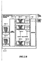
- Figs. 2A and 2B show an embodiment of a mobile communication system in accordance with the present invention.
- the reference numeral 100 designates mobile stations
- 101 designates base stations
- 102 designates a transmitter and receiver.
- the reference numeral 107 designates a switching center in the mobile communication system.
- the reference numerals 103 and 109 designate ATM cell assembler/disassemblers in the base station 101 and the mobile services switching center 107.
- the reference numeral 104 designates a transmitted frame assembler/disassembler in the base station 101, which has a function of placing ATM cells generated by the ATM cell assembler/disassemblers 103 in predetermined positions in a transmitted frame in accordance with the call types to be transmitted, and a function of picking up ATM cells by disassembling a received transmitted frame.
- the reference numeral 105 designates transmitted frame assembler/disassemblers in the mobileservices switching center 107, which transmit and receive transmitted frames 200 in synchronism with the transmitted frame assembler/disassembler 104 in the base station 101.
- the reference numeral 108 designates codec equipment including the ATM cell assembler/disassemblers 109 and codecs 110 in the mobile services switching center 107 for carrying out code conversion.
- the reference numeral 111 designates a switch for connecting a telephone 112 with one of the ATM cell assembler/disassemblers 109 in the mobile services switching center 107.
- the reference numeral 112 designates a telephone, and 113 designates channels for transmitting the transmitted frames 200.
- the mobile stations 100-1, 100-2 and 100-3 with different call types of communications are moving in the radio zone controlled by the base station 101-1, thus carrying out communications.
- radio channels have been selected for the communications between the respective mobile stations 101 and the transmitter and receiver 102 in the base station 101-1.
- ATM links have been established between the ATM cell assembler/disassemblers 103 in the base station and the ATM cell assembler/disassemblers 109 in the mobile services switching center to enable the communications.
- the switch 111 is set to connect the codec 110-1 with the telephone 112, for example.
- a coded signal of a call type a transmitted from the mobile station 100-1 is passed through a radio channel ch1, received by the transmitter and receiver 102 in the base station 101-1, and divided into cells by the ATM cell assembler/disassembler 103-1, to carry out the transmission by the ATM cell. Similar processings are carried out with the mobile stations 100-2 and 100-3 so that the respective ATM cells are sent to the transmitted frame assembler/disassembler 104 .
- the transmitted frame assembler/disassembler 104 places the ATM cells on the cell slots prepared for transmitting the ATM cells of different call types, and assembles them into transmitted frame 200 at every interval T to be transmitted periodically.
- the transmitted frame 200 is transferred through the channel 113, and is synchronously received by one of the transmitted frame assembler/disassemblers 105 in the mobile services switching center 107, in which the transmitted frame 200 is disassembled into ATM cells.
- the disassembled ATM cells are transferred to an ATM switch 106.
- the ATM cells are routed to the ATM cell assembler/disassemblers 109 in accordance with the ATM headers by the ATM switch 106.
- the routed ATM cells are converted into coded signals by the ATM cell assembler/disassemblers 109 and are decoded into voice codes by the codecs 110.
- the voice signals decoded by the codecs are sent to the telephone 112, for example, through the switch 111.
- a signal from the telephone 112 is transmitted to a mobile station 100-1 through a similar processing.
- the foregoing operation enables the communications between the mobile station and the telephone.
- transmitted frames 200-1 - 200-4 are prepared in the transmitted frame assembler/disassembler 104.
- Each transmitted frame includes transmitted slots such as 201-1 - 201-3 for transferring the ATM cells corresponding to the calls.
- the transmitted frames are generated by the transmitted frame assembler/disassembler 104 at every interval T to be sent over the channels.
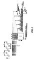
- the calls a, b and c are controlled such that they are generated with their phase shifted by T/3 interval as shown in Fig. 3, thereby being placed on the frame without delay.
- generating the calls with their phase shifted makes it possible for the information of the calls to be assembled into the transmitted frames and transferred at the interval T without delay or collision.
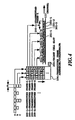
- Fig. 4 is a diagram illustrating the transmission algorithm applied to a case where there is only one call for each of the different call types.
- the reference numeral 200 designates transmitted frames, each of which accommodates a fixed number of cell slots 201 and is transmitted at the fixed interval T, and 201 designates cell slots reserved for transmitting the ATM cells of respective call types.
- the transmission period of the call type a is T
- This can be implemented by preparing in the transmitted frame assembler/disassembler 104 the transmitted frame 200 consisting of cell slots 201-1, 201-2 and 201-3 for transferring the respective call type cells at every transfer period as shown in Fig. 4 so that the transmitted frames are scheduled to be sent over the channel 113 at every interval T without delay.
- a dummy cell is inserted to form a vacant cell slot 202.
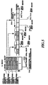
- Fig. 5 is a diagram illustrating the transmission algorithm extended to be applied to a plurality of calls for each of the different call types.
- the reference numeral 300 designates transmitted frames which accommodate the same number of cell slot groups as that of the call types and are transferred at the fixed interval T.
- the reference numeral 301 designates cell slot groups each consisting of a plurality of consecutive cell slots reserved in advance for transferring the ATM cells conveying the respective call types.
- the transmitted frame 300 including cell slot groups consisting of transmitted cell slots of the same call type is prepared only when a plurality of calls of the same call type occur at the same time.
- the transmitted frames can be scheduled to be sent over the channel 113 at every interval T without delay.
- This embodiment is also applied to the mobile communication system as shown in Figs. 2A and 2B.
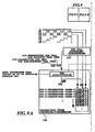
- Fig. 6 is a diagram illustrating the transmission algorithm of the present embodiment, which handles one call for each of the different call types in the mobile communication system as shown in Figs. 2A and 2B.
- the reference numeral 200 designates transmitted frames which accommodate a fixed number of cell slots 201 and shared cell slots 203, and are transmitted at a fixed interval T.
- the reference numeral 201 designates cell slots reserved in advance for transmitting the ATM cells conveying the respective call types.
- the reference numerals 203 designates shared slots which are used instead of the cell slots 201 in the case where a call occurs and the cell slots 201 for that call type have already been used for the communication.
- the call types b and c can be transmitted at periods equal to twice and four times the period T, respectively.
- This can be implemented by preparing in the transmitted frame assembler/disassembler 104 shown in Figs. 2A and 2B the transmitted frames 201 each consisting of the cell slots 201-1, 201-2 and 201-3 for transferring the respective call type cells as in Fig. 4 so that the transmitted frames are scheduled to be sent over the channel 113 at every interval T without delay.
- a shared cell slot 203 is reserved to transfer the new call in Fig. 6.
- the shared cell slot enables the new call to be transferred without delay.
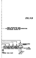
- Fig. 7 is a diagram illustrating an extended transmission algorithm applied to a plurality of calls for each of the different call types.
- the reference numeral 300 designates transmitted frames which accommodate the same number of cell slot groups 301 and shared cell slot groups 303 as that of the call types, and which are transferred at the fixed interval T.
- the reference numeral 301 designates cell slot groups each consisting of a plurality of consecutive cell slots reserved in advance for transferring the ATM cells conveying the respective call types.
- the reference numeral 303 designates the shared cell slot groups used instead of the cell slot groups 301 when there is no vacant cell slot because the cell slot groups 301 have already been used up which are to be employed for transferring the call type at the occurrence of the call.
- handling a plurality of calls per call type enables greater number of calls to be transmitted than in the first embodiment by using the vacant cell slot groups 302 as the shared slot groups 303 when no available assigned cell slot is present in the cell slot groups used for ordinary transmission.
- an incomplete call will occur if the number of calls exceeds the number of the available shared cell slots in the shared cell slot groups.
- a shared cell slot is assigned to an overflowed call in accordance with its priority when the number of calls exceeds the number of available shared slots prepared in the shared cell slots or the shared cell groups, thereby being transmitted in preference. This makes it possible to reduce the probability that the priority call ends with an incomplete call.
- Fig. 8 shows the ATM header, in which the reference numeral 401 designates CLP (Cell Loss Priority) standardized by ITU-T, an identifier for identifying the priority of the cell.
- CLP Cell Loss Priority
- the CLP of the ATM header enables the priority of the cell to be identified, and when the bit of the CLP is set, the cell is handled as a low priority cell.
- the priority call is a call whose CLP bit is not set in its ATM cell header.
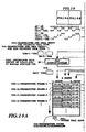
- Figs. 9A and 9B are diagrams illustrating the transfer algorithm when the present embodiment is applied to one call for each different call type. This embodiment also applied to the configuration of the mobile communication system as shown in Fig. 1.
- the reference numeral 200 designates transmitted frames which accommodate a fixed number of cell slots 201 and shared cell slots 203, and are transferred at the fixed interval T.
- the reference numeral 201 designates cell slots reserved in advance for transmitting the ATM cells conveying the respective call types.
- the reference numeral 203 designates shared cell slots used instead of the cell slots 201 when the cell slots 201 have already been used up for transmitting the call type when the call occurs.
- the reference numeral 204 designates an ATM cell for carrying a priority call
- 205 designates an ATM cell for carrying a non-priority call.
- the ATM cell assembler/disassemblers 103 in the base station 101 and the ATM cell assembler/disassemblers 109 in the mobileservices switching center 107 in Figs. 2A and 2B decide whether the information in the ATM cells exchanged to one another indicates the priority call or non-priority call at the step of establishing communications.
- the ATM cell assembler/disassemblers 103 and 109 set the CLP identifier 401 in Fig. 8 to "0" when transmitting the priority call, and to "1" when transmitting the non-priority call.
- the transmitted frame assembler/disassembler 104 decides whether the information carried by the ATM cell indicates the priority call or non-priority call by checking the CLP identifier 401 in the ATM header.
- the call types b and c can be transmitted at intervals equal to twice and four times the period T, respectively.
- This can be implemented as in the embodiments shown in Figs. 4 and 6 by preparing the transmitted frames 201 each consisting of the cell slots 201-1, 201-2 and 201-3 for transferring the respective call type cells, and by scheduling the transmitted frames such that they are sent over the channel 113 at every interval T without delay.
- Figs. 9A and 9B one call per call type a, b or c is assumed as in Figs. 4 and 6. If a new call occurs for the call types b and c, a shared cell slot 203 is reserved to transfer the new call as in Fig. 5. This enables the new call to be transferred without delay as in the embodiment 2 shown in Fig. 5.
- new calls b2 and b3 occur as shown in Figs. 9A and 9B, and that the call b2 is a priority call and the call b3 is a non-priority call.
- the ATM cell assembler/disassemblers 103 in Figs. 2A and 2B assign information to the CLP 401 in the ATM headers in the ATM cells for transmitting the respective calls such that the priority and non-priority can be identified.
- the transmitted frame assembler/disassembler 104 checks the CLP 401 of the ATM cells 204 and 205 sent out of the ATM cell assembler/disassemblers 103, assigns the shared cell slot to the ATM cell 204 carrying the priority call, and provides the mobile station 100 and mobile services switching center 107 with the incomplete call report of the call b3 because the cell slot cannot be assigned to the ATM cell 205 for transmitting the non-priority call.
- a shared cell slot is assigned to an overflowed call in accordance with its priority when the number of calls exceeds the number of available shared slots prepared in the shared cell slots, thereby being transmitted in preference. This makes it possible to reduce the probability that the priority call ends with an incomplete call.
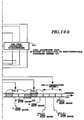
- Figs. 10A and 10B are diagrams illustrating extended transmission algorithm applied to a plurality of calls for each of the different call types.
- the reference numeral 300 designates transmitted frames which accommodate the same number of cell slot groups 301 and shared cell slot groups 303 as that of the call types, and which are transferred at the fixed interval T.
- the reference numeral 301 designates cell slot groups each consisting of a plurality of consecutive cell slots reserved in advance for transferring the ATM cells conveying the respective call types.
- the reference numeral 303 designates shared cell slot groups used instead of the cell slot groups 301 when there is no vacant cell slot because the cell slot group 301 have already been used which are to be used for transferring the call type at the occurrence of the call.
- the reference numeral 304 designates an ATM cell group for carrying the priority call, and 305 designates an ATM cell group for carrying the non-priority call.
- the transmitted frame assembler/disassembler 104 checks the CLPs 401 of the ATM cell groups 304 and 305 sent out of the ATM cell assembler/disassemblers 103 as in the case described in connection with Figs. 9A and 9B. Then, the shared cell slot group is assigned to the ATM cell group 304 which transfers the priority call. The shared cell slots in the shared cell slot group are assigned to the ATM cell group 305 which carries the non-priority call as much as possible to transfer the calls. With regard to the remaining calls in the ATM cell group 305, the incomplete call report is sent to the mobile station and the mobile services switching center 107 because the cell slot cannot be assigned to them.
- Figs. 3-7 and 9A-10B the algorithms are described for assembling the transmitted frame in the transmitted frame assembler/disassembler 104 of the base station. Like operations are also carried out in the transmitted frame assembler/disassembler 105 of the mobileservices switching center.
- a shared cell slot is assigned to an overflowed call in accordance with its priority when the number of calls exceeds the number of available shared slots prepared in the shared cell slot groups, thereby being transmitted in preference. This makes it possible to reduce the probability that the priority call ends with an incomplete call.
- the present invention enables multiple connections of cells of the same call types or of cells bearing different call type information with different information transfer rates to be sent periodically without delay by means of particular cell slot groups, thereby improving the communication quality.
- the present invention can increase the information transmission efficiency by handling overflowed calls such that they do not end with an incomplete call even when the number of calls exceeds the number of cell slots prepared in the cell slot group for each call type.
- the present invention can reduce the probability that the priority call ends with an incomplete call by assigning a shared cell slot to an overflowed call in accordance with its priority when the number of calls exceeds the number of available shared cell slots prepared in the shared cell slot group.
Landscapes
- Engineering & Computer Science (AREA)
- Computer Networks & Wireless Communication (AREA)
- Signal Processing (AREA)
- Data Exchanges In Wide-Area Networks (AREA)
- Mobile Radio Communication Systems (AREA)
Description
- The present invention relates to structuring channels between a mobile services switching center and base stations in mobile communications using ATM (Asynchronous Transfer Mode), and more particularly to a system which periodically transfers ATM cells generated for each of a plurality of call types by means of a frame consisting of multiple cell slots.
- Establishing channels between a mobile services switching center and base stations using ATM (Asynchronous Transfer Mode) has been conventionally implemented. In this case, it is necessary to send multiple connections of cells from a base station to the mobile services switching center through the same channel. Sending ATM cells over the same channel presents various problems because the base station handles speech information from mobile stations with severe delay condition at low CBR (constant bit rate).
- One of the conventional techniques sequentially transmits, under competitive control, a plurality of connections of ATM cells carrying the same call type over the same channel. This is shown in Fig. 1.
- The transmission system under the competitive control as shown in Fig. 1 inevitably results in waiting delay for transmission regardless of the call types when the competitive control is carried out.
- EP-A-0662778 describes a transmission system for communication over wire circuits between a switching centre and a multiplicity of radio base stations. Fixed-length data cells are constructed by combining in parallel a plurality of short data packets. A time limit is placed on the construction of a fixed-length data cell, the limit depending on whether the short data packets represent voice or non-voice communication. When the time limit is reached the fixed-length data cell is transmitted, any spare capacity within the cell being filled with dummy data.
- The present invention provides a fixed length cell transmission system for use in a mobile communication system carrying out information transmission between a mobile services switching center and a base station using a fixed length cell, the transmission system comprising:
- means, adapted to handle a plurality of calls, for preparing a cell slot for transmission when a fixed length cell bearing information of a call is generated; and
- means for carrying out periodic transfer of a frame consisting of a plurality of the cell slots, characterized by:
- means for synchronizing the generation timing of the cell and the transfer interval of the frame.
-
- Embodiments of the present invention reduce the mismatch between the generation timing and transmission timing of a cell or waiting time for transmission as much as possible by periodically transmitting a frame consisting of cell slots prepared to send each of fixed length cells (ATM cells) bearing information about a call type of the same kind or call types different in information transfer rates and so on.
- This makes it possible to minimize the delay from the generation to the transmission of the cells, and to ensure the quality in voice or real time information transmission.
-
- Fig. 1 is a diagram illustrating a conventional method for sending a plurality of call ATM cells over the same channel;
- Figs. 2A and 2B are block diagrams showing a mobile communication system in accordance with the present invention;
- Fig. 3 is a diagram illustrating transmission algorithm of the same call type;
- Fig. 4 is a diagram illustrating transmission algorithm of different call types;
- Fig. 5 is a diagram illustrating transmission algorithm extended to a plurality of calls of different types;
- Fig. 6 is a diagram illustrating an
embodiment 3 applied to a case which handles only one call for each of different call types; - Fig. 7 is a diagram illustrating the
embodiment 3 applied to an extended case which handles a plurality of calls for each of different call types; - Fig. 8 is a diagram showing an ATM header;
- Figs. 9A and 9B are
diagrams illustrating embodiment 4 applied to a case which handles only one call for each of different call types; and - Figs. 10A and 10B are
diagrams illustrating embodiment 4 applied to an extended case which handles a plurality of calls for each of different call types. -
- The embodiments of the invention will now be described with reference to the accompanying drawings.
- Figs. 2A and 2B show an embodiment of a mobile communication system in accordance with the present invention. In Figs. 2A and 2B, the
reference numeral 100 designates mobile stations, 101 designates base stations, and 102 designates a transmitter and receiver. Thereference numeral 107 designates a switching center in the mobile communication system. Thereference numerals base station 101 and the mobileservices switching center 107. Thereference numeral 104 designates a transmitted frame assembler/disassembler in thebase station 101, which has a function of placing ATM cells generated by the ATM cell assembler/disassemblers 103 in predetermined positions in a transmitted frame in accordance with the call types to be transmitted, and a function of picking up ATM cells by disassembling a received transmitted frame. Thereference numeral 105 designates transmitted frame assembler/disassemblers in themobileservices switching center 107, which transmit and receive transmittedframes 200 in synchronism with the transmitted frame assembler/disassembler 104 in thebase station 101. Thereference numeral 108 designates codec equipment including the ATM cell assembler/disassemblers 109 and codecs 110 in the mobileservices switching center 107 for carrying out code conversion. Thereference numeral 111 designates a switch for connecting atelephone 112 with one of the ATM cell assembler/disassemblers 109 in the mobileservices switching center 107. Thereference numeral 112 designates a telephone, and 113 designates channels for transmitting the transmittedframes 200. - The operation of the units and circuits, and the flow of communication signals conveyed over channels of the respective embodiments in accordance with the present invention will now be described with reference to Figs. 2A and 2B.
- The mobile stations 100-1, 100-2 and 100-3 with different call types of communications are moving in the radio zone controlled by the base station 101-1, thus carrying out communications. In this case, radio channels have been selected for the communications between the respective
mobile stations 101 and the transmitter andreceiver 102 in the base station 101-1. In addition, ATM links have been established between the ATM cell assembler/disassemblers 103 in the base station and the ATM cell assembler/disassemblers 109 in the mobile services switching center to enable the communications. It is further assumed that theswitch 111 is set to connect the codec 110-1 with thetelephone 112, for example. - A coded signal of a call type a transmitted from the mobile station 100-1 is passed through a radio channel ch1, received by the transmitter and
receiver 102 in the base station 101-1, and divided into cells by the ATM cell assembler/disassembler 103-1, to carry out the transmission by the ATM cell. Similar processings are carried out with the mobile stations 100-2 and 100-3 so that the respective ATM cells are sent to the transmitted frame assembler/disassembler 104 . - The transmitted frame assembler/
disassembler 104 places the ATM cells on the cell slots prepared for transmitting the ATM cells of different call types, and assembles them into transmittedframe 200 at every interval T to be transmitted periodically. - The transmitted
frame 200 is transferred through thechannel 113, and is synchronously received by one of the transmitted frame assembler/disassemblers 105 in the mobileservices switching center 107, in which the transmittedframe 200 is disassembled into ATM cells. The disassembled ATM cells are transferred to anATM switch 106. - The ATM cells are routed to the ATM cell assembler/
disassemblers 109 in accordance with the ATM headers by theATM switch 106. The routed ATM cells are converted into coded signals by the ATM cell assembler/disassemblers 109 and are decoded into voice codes by the codecs 110. The voice signals decoded by the codecs are sent to thetelephone 112, for example, through theswitch 111. - On the other hand, a signal from the
telephone 112 is transmitted to a mobile station 100-1 through a similar processing. - Thus, the foregoing operation enables the communications between the mobile station and the telephone.
- Next, generating methods will be described of the transmitted frames in the mobile communication system thus configured in accordance with the present invention.
- A case (embodiment 1) will now be described in which the same call type (which has the same transfer period) is transferred using the transmitted frame.
- Let us assume that there are three calls a, b and c of the same type, and their information generating periods are the same, which is T. The processing time is the same which is required for the information to be placed into the payload of a fixed length packet such as the ATM cell because they have the same call type.
- To transmit the three calls a, b and c over the same channel, transmitted frames 200-1 - 200-4 are prepared in the transmitted frame assembler/
disassembler 104. Each transmitted frame includes transmitted slots such as 201-1 - 201-3 for transferring the ATM cells corresponding to the calls. The transmitted frames are generated by the transmitted frame assembler/disassembler 104 at every interval T to be sent over the channels. - The calls a, b and c are controlled such that they are generated with their phase shifted by T/3 interval as shown in Fig. 3, thereby being placed on the frame without delay. Thus generating the calls with their phase shifted makes it possible for the information of the calls to be assembled into the transmitted frames and transferred at the interval T without delay or collision.
- Next, referring to Figs. 4 and 5, the algorithm of assembling operation of the transmitted frame assembler/
disassembler 104 will be described. - Fig. 4 is a diagram illustrating the transmission algorithm applied to a case where there is only one call for each of the different call types. In Fig. 4, the
reference numeral 200 designates transmitted frames, each of which accommodates a fixed number of cell slots 201 and is transmitted at the fixed interval T, and 201 designates cell slots reserved for transmitting the ATM cells of respective call types. - Let us assume that there are three call types a, b and c.
- Furthermore, it is assumed that they have different information transfer rates (the other conditions such as quality required for the transmission are assumed to be the same), and that the information transfer rates have the following simple ratios.
- The ratios of intervals required for the information to be placed into the ATM cell payloads are as follows (this holds true when a fixed length packet is used instead of the standard ATM cell as a transmitting medium).
- To transmit the call types a, b and c without delay over the same channel, they must be placed on the transmission line at the following periods.
- If the transmission period of the call type a is T, it is necessary for the call types b and c to be transmitted at the periods twice and four times the period of a. This can be implemented by preparing in the transmitted frame assembler/
disassembler 104 the transmittedframe 200 consisting of cell slots 201-1, 201-2 and 201-3 for transferring the respective call type cells at every transfer period as shown in Fig. 4 so that the transmitted frames are scheduled to be sent over thechannel 113 at every interval T without delay. - In Fig. 4, if there appears no cell for transferring the call types a, b and c during the frame transmission interval T, a dummy cell is inserted to form a
vacant cell slot 202. - Fig. 5 is a diagram illustrating the transmission algorithm extended to be applied to a plurality of calls for each of the different call types. In Fig. 5, the reference numeral 300 designates transmitted frames which accommodate the same number of cell slot groups as that of the call types and are transferred at the fixed interval T. The reference numeral 301 designates cell slot groups each consisting of a plurality of consecutive cell slots reserved in advance for transferring the ATM cells conveying the respective call types.
- As in Fig. 4, let us assume that there are three call types a, b and c, and they have different information transfer rates (the other conditions such as quality required for the transmission are assumed to be the same) as follows.
- In this case, the ratios of time periods required for the information to be placed into the ATM cell payloads are as follows as in Fig. 3 (this holds true when a fixed length packet is used instead of the standard ATM cell as a transmitting medium).
- As shown in Fig. 5, the transmitted frame 300 including cell slot groups consisting of transmitted cell slots of the same call type is prepared only when a plurality of calls of the same call type occur at the same time. The transmitted frames can be scheduled to be sent over the
channel 113 at every interval T without delay. - In Fig. 5, if no cell slot group appears for transferring the call types a, b and c during the frame transmission interval T of the transmitted frame, a dummy cell is inserted to form a vacant
cell slot group 302. - In the foregoing transmission method, if the number of calls exceeds the number of cell slots for respective call types or the number of cell slots prepared for the cell slot group, it is inevitable that some calls become an incomplete call because they have no transmission means.
- An embodiment will now be described which can improve the information transfer efficiency by transmitting overflowed calls even if the number of calls exceeds the number of cell slots for respective call types or the number of cell slots prepared for the cell slot group, thereby completing the transmission of the overflowed calls.
- This embodiment is also applied to the mobile communication system as shown in Figs. 2A and 2B.
- Fig. 6 is a diagram illustrating the transmission algorithm of the present embodiment, which handles one call for each of the different call types in the mobile communication system as shown in Figs. 2A and 2B. In Fig. 6, the
reference numeral 200 designates transmitted frames which accommodate a fixed number of cell slots 201 and sharedcell slots 203, and are transmitted at a fixed interval T. The reference numeral 201 designates cell slots reserved in advance for transmitting the ATM cells conveying the respective call types. The reference numerals 203 designates shared slots which are used instead of the cell slots 201 in the case where a call occurs and the cell slots 201 for that call type have already been used for the communication. - The algorithm of the assembling operation of the transmitted frame assembler/
disassembler 104 will now be described with reference to Fig. 6. - The conditions of the call types a, b and c are the same as those of the embodiment as shown in Fig. 4.
- Accordingly, when the transfer period of the call type a is T, the call types b and c can be transmitted at periods equal to twice and four times the period T, respectively. This can be implemented by preparing in the transmitted frame assembler/
disassembler 104 shown in Figs. 2A and 2B the transmitted frames 201 each consisting of the cell slots 201-1, 201-2 and 201-3 for transferring the respective call type cells as in Fig. 4 so that the transmitted frames are scheduled to be sent over thechannel 113 at every interval T without delay. - In Fig. 6, one call per call type a, b or c is assumed as in Fig. 4. However, if a new call occurs for the call types b and c, a shared
cell slot 203 is reserved to transfer the new call in Fig. 6. The shared cell slot enables the new call to be transferred without delay. - Fig. 7 is a diagram illustrating an extended transmission algorithm applied to a plurality of calls for each of the different call types. In Fig. 7, the reference numeral 300 designates transmitted frames which accommodate the same number of cell slot groups 301 and shared
cell slot groups 303 as that of the call types, and which are transferred at the fixed interval T. The reference numeral 301 designates cell slot groups each consisting of a plurality of consecutive cell slots reserved in advance for transferring the ATM cells conveying the respective call types. Thereference numeral 303 designates the shared cell slot groups used instead of the cell slot groups 301 when there is no vacant cell slot because the cell slot groups 301 have already been used up which are to be employed for transferring the call type at the occurrence of the call. - As in the case described in connection with Fig. 6, which handles one call per call type, handling a plurality of calls per call type enables greater number of calls to be transmitted than in the first embodiment by using the vacant
cell slot groups 302 as the sharedslot groups 303 when no available assigned cell slot is present in the cell slot groups used for ordinary transmission. - In the transmission of the overflowed call using the shared cell slots or the shared cell slot groups described in the
embodiment 3, an incomplete call will occur if the number of calls exceeds the number of the available shared cell slots in the shared cell slot groups. - In this embodiment, a shared cell slot is assigned to an overflowed call in accordance with its priority when the number of calls exceeds the number of available shared slots prepared in the shared cell slots or the shared cell groups, thereby being transmitted in preference. This makes it possible to reduce the probability that the priority call ends with an incomplete call.
- The priority call will now be described. Fig. 8 shows the ATM header, in which the
reference numeral 401 designates CLP (Cell Loss Priority) standardized by ITU-T, an identifier for identifying the priority of the cell. Thus, the CLP of the ATM header enables the priority of the cell to be identified, and when the bit of the CLP is set, the cell is handled as a low priority cell. When the channels aggregate, the cell with its CLP bit being set is relinquished first. In other words, the priority call is a call whose CLP bit is not set in its ATM cell header. - Figs. 9A and 9B are diagrams illustrating the transfer algorithm when the present embodiment is applied to one call for each different call type. This embodiment also applied to the configuration of the mobile communication system as shown in Fig. 1.
- In Figs. 9A and 9B, the
reference numeral 200 designates transmitted frames which accommodate a fixed number of cell slots 201 and sharedcell slots 203, and are transferred at the fixed interval T. The reference numeral 201 designates cell slots reserved in advance for transmitting the ATM cells conveying the respective call types. Thereference numeral 203 designates shared cell slots used instead of the cell slots 201 when the cell slots 201 have already been used up for transmitting the call type when the call occurs. Thereference numeral 204 designates an ATM cell for carrying a priority call, and 205 designates an ATM cell for carrying a non-priority call. - The identifying method of the priority and non-priority ATM calls will now be described.
- It is possible for the ATM cell assembler/
disassemblers 103 in thebase station 101 and the ATM cell assembler/disassemblers 109 in themobileservices switching center 107 in Figs. 2A and 2B to decide whether the information in the ATM cells exchanged to one another indicates the priority call or non-priority call at the step of establishing communications. The ATM cell assembler/disassemblers CLP identifier 401 in Fig. 8 to "0" when transmitting the priority call, and to "1" when transmitting the non-priority call. - The transmitted frame assembler/
disassembler 104 decides whether the information carried by the ATM cell indicates the priority call or non-priority call by checking theCLP identifier 401 in the ATM header. - Other methods capable of identifying the priority call and non-priority call can also be applied to the present invention as long as they can decide the priority in the transmitted frame assembler/
disassembler 104. - The operation of the embodiment which makes priority decision using the CLP identifier will now be described with reference to Figs. 9A and 9B.
- The conditions of the call types a, b and c are the same as those of the embodiments as shown in Figs. 4-7.
- Accordingly, when the transfer period of the call type a is T, the call types b and c can be transmitted at intervals equal to twice and four times the period T, respectively. This can be implemented as in the embodiments shown in Figs. 4 and 6 by preparing the transmitted frames 201 each consisting of the cell slots 201-1, 201-2 and 201-3 for transferring the respective call type cells, and by scheduling the transmitted frames such that they are sent over the
channel 113 at every interval T without delay. - In Figs. 9A and 9B, one call per call type a, b or c is assumed as in Figs. 4 and 6. If a new call occurs for the call types b and c, a shared
cell slot 203 is reserved to transfer the new call as in Fig. 5. This enables the new call to be transferred without delay as in theembodiment 2 shown in Fig. 5. - Let us assume, as shown in Figs. 9A and 9B, that the number of cell slots available for the call type a is one, that for the call type b is one, and that for the call type c is four, and that the number of the shared cell slots available for the ATM cell transfer is one.
- It is further assumed that new calls b2 and b3 occur as shown in Figs. 9A and 9B, and that the call b2 is a priority call and the call b3 is a non-priority call. In this case, the ATM cell assembler/
disassemblers 103 in Figs. 2A and 2B assign information to theCLP 401 in the ATM headers in the ATM cells for transmitting the respective calls such that the priority and non-priority can be identified. - The transmitted frame assembler/
disassembler 104 checks theCLP 401 of theATM cells disassemblers 103, assigns the shared cell slot to theATM cell 204 carrying the priority call, and provides themobile station 100 and mobileservices switching center 107 with the incomplete call report of the call b3 because the cell slot cannot be assigned to theATM cell 205 for transmitting the non-priority call. - In this embodiment, a shared cell slot is assigned to an overflowed call in accordance with its priority when the number of calls exceeds the number of available shared slots prepared in the shared cell slots, thereby being transmitted in preference. This makes it possible to reduce the probability that the priority call ends with an incomplete call.
- Figs. 10A and 10B are diagrams illustrating extended transmission algorithm applied to a plurality of calls for each of the different call types. In Figs. 10A and 10B, the reference numeral 300 designates transmitted frames which accommodate the same number of cell slot groups 301 and shared
cell slot groups 303 as that of the call types, and which are transferred at the fixed interval T. The reference numeral 301 designates cell slot groups each consisting of a plurality of consecutive cell slots reserved in advance for transferring the ATM cells conveying the respective call types. Thereference numeral 303 designates shared cell slot groups used instead of the cell slot groups 301 when there is no vacant cell slot because the cell slot group 301 have already been used which are to be used for transferring the call type at the occurrence of the call. Thereference numeral 304 designates an ATM cell group for carrying the priority call, and 305 designates an ATM cell group for carrying the non-priority call. - When handling a plurality of calls per call type, the transmitted frame assembler/
disassembler 104 checks theCLPs 401 of theATM cell groups 304 and 305 sent out of the ATM cell assembler/disassemblers 103 as in the case described in connection with Figs. 9A and 9B. Then, the shared cell slot group is assigned to theATM cell group 304 which transfers the priority call. The shared cell slots in the shared cell slot group are assigned to the ATM cell group 305 which carries the non-priority call as much as possible to transfer the calls. With regard to the remaining calls in the ATM cell group 305, the incomplete call report is sent to the mobile station and the mobileservices switching center 107 because the cell slot cannot be assigned to them. - In Figs. 3-7 and 9A-10B, the algorithms are described for assembling the transmitted frame in the transmitted frame assembler/
disassembler 104 of the base station. Like operations are also carried out in the transmitted frame assembler/disassembler 105 of the mobileservices switching center. - Thus, a shared cell slot is assigned to an overflowed call in accordance with its priority when the number of calls exceeds the number of available shared slots prepared in the shared cell slot groups, thereby being transmitted in preference. This makes it possible to reduce the probability that the priority call ends with an incomplete call.
- As described above, the present invention enables multiple connections of cells of the same call types or of cells bearing different call type information with different information transfer rates to be sent periodically without delay by means of particular cell slot groups, thereby improving the communication quality.
- Furthermore, the present invention can increase the information transmission efficiency by handling overflowed calls such that they do not end with an incomplete call even when the number of calls exceeds the number of cell slots prepared in the cell slot group for each call type.
- Moreover, the present invention can reduce the probability that the priority call ends with an incomplete call by assigning a shared cell slot to an overflowed call in accordance with its priority when the number of calls exceeds the number of available shared cell slots prepared in the shared cell slot group.
Claims (6)
- A fixed length cell transmission system for use in a mobile communication system carrying out information transmission between a mobile services switching center (107) and a base station (101) using a fixed length cell, said transmission system comprising:means (104, 105), adapted to handle a plurality of calls, for preparing a cell slot (201, 301) for transmission when a fixed length cell bearing information of a call is generated;means (113) for carrying out periodic transfer of a frame (200, 300) consisting of a plurality of the cell slots; andmeans for synchronizing the generation timing of the cell and the transfer interval of said frame.
- The transmission system as claimed in claim 1, wherein said fixed length cell is an ATM cell.
- The transmission system as claimed in claim 1 or 2, wherein said frame (200) consists of a plurality of cell slots (201) which have one to one correspondence with the plurality of calls.
- The transmission system as claimed in claim 1 or 2, wherein said frame (300) consists of a plurality of cell slots (301), each of said cell slots belonging to any one of a plurality of cell slot groups, and each of said cell slot groups including a plurality of cell slots for each of said calls.
- The transmission system as claimed in any one of claims 1 to 4, comprising means for using a vacant cell slot in a frame (200, 300) as a shared cell slot (203, 303) available among the plurality of calls.
- The transmission system as claimed in claim 5, comprising means (104, 105) for assigning said shared cell slot to a cell (204, 304) for a priority call.
Applications Claiming Priority (4)
| Application Number | Priority Date | Filing Date | Title |
|---|---|---|---|
| JP28755395 | 1995-11-06 | ||
| JP287553/95 | 1995-11-06 | ||
| JP28755395 | 1995-11-06 | ||
| PCT/JP1996/003227 WO1997017779A1 (en) | 1995-11-06 | 1996-11-05 | System for transmission between base station and exchange of mobile communication using fixed-length cell |
Publications (3)
| Publication Number | Publication Date |
|---|---|
| EP0820165A1 EP0820165A1 (en) | 1998-01-21 |
| EP0820165A4 EP0820165A4 (en) | 1999-12-15 |
| EP0820165B1 true EP0820165B1 (en) | 2004-05-06 |
Family
ID=17718841
Family Applications (1)
| Application Number | Title | Priority Date | Filing Date |
|---|---|---|---|
| EP96935539A Expired - Lifetime EP0820165B1 (en) | 1995-11-06 | 1996-11-05 | System for transmission between base station and exchange of mobile communication using fixed-length cell |
Country Status (6)
| Country | Link |
|---|---|
| US (2) | US6442149B1 (en) |
| EP (1) | EP0820165B1 (en) |
| JP (1) | JP3183351B2 (en) |
| CN (1) | CN1110161C (en) |
| DE (1) | DE69632399T2 (en) |
| WO (1) | WO1997017779A1 (en) |
Families Citing this family (19)
| Publication number | Priority date | Publication date | Assignee | Title |
|---|---|---|---|---|
| US7570645B2 (en) * | 2000-01-18 | 2009-08-04 | Viasat, Inc. | Frame format and frame assembling/disassembling method for the frame format |
| US6931009B1 (en) * | 1997-07-15 | 2005-08-16 | Viasat, Inc. | Frame format and frame assembling/disassembling method for the frame format |
| CN1245819C (en) | 1997-09-16 | 2006-03-15 | Ntt移动通信网株式会社 | Packet transmission method, packet transmission device, radio frame transmission method, mobile communication method, mobile communication system, and exchange |
| US6381647B1 (en) * | 1998-09-28 | 2002-04-30 | Raytheon Company | Method and system for scheduling network communication |
| DE19919177A1 (en) * | 1999-04-28 | 2000-11-02 | Philips Corp Intellectual Pty | Network with multiple network clusters for the wireless transmission of packets |
| US8254394B1 (en) | 1999-06-29 | 2012-08-28 | Cisco Technology, Inc. | Technique for providing constant bit rate (CBR) service over a time-slotted access channel |
| GB9915327D0 (en) * | 1999-06-30 | 1999-09-01 | Nortel Networks Corp | Packet interface and method of packetizing information |
| US7215650B1 (en) | 1999-08-16 | 2007-05-08 | Viasat, Inc. | Adaptive data rate control for narrowcast networks |
| US7046678B2 (en) * | 2000-02-18 | 2006-05-16 | At & T Corp. | Channel efficiency based packet scheduling for interactive data in cellular networks |
| FR2806244B1 (en) * | 2000-03-13 | 2003-05-30 | Mitsubishi Electric Inf Tech | TRANSMISSION METHOD BETWEEN A BASE STATION OF AN ACCESS NETWORK AND AN ACCESS NETWORK CONTROLLER OF A TELECOMMUNICATIONS SYSTEM |
| US7230908B2 (en) * | 2000-07-24 | 2007-06-12 | Viasat, Inc. | Dynamic link assignment in a communication system |
| JP3596603B2 (en) | 2000-10-13 | 2004-12-02 | 日本電気株式会社 | Scheduling system and scheduling method |
| CN100474975C (en) | 2001-08-21 | 2009-04-01 | 诺基亚有限公司 | Transmission of data in communication network |
| EP1645095B1 (en) * | 2003-07-03 | 2020-09-02 | Panasonic Corporation | Transmitter and method for digital multi-carrier transmission using wavelets |
| CN100450228C (en) * | 2005-06-01 | 2009-01-07 | 华为技术有限公司 | Method for eliminating relativity of transmission delay between real time service and nonreal time service |
| JP4628254B2 (en) * | 2005-11-04 | 2011-02-09 | 株式会社エヌ・ティ・ティ・ドコモ | Base station and data transfer method |
| US20080159332A1 (en) * | 2006-12-29 | 2008-07-03 | John Christian Martinez | Methods and devices for using variable length subpackets in data transmissions |
| KR101840712B1 (en) | 2015-04-24 | 2018-03-21 | 주식회사 리그닌 | Method for manufacturing liquid separable mask pack packing vessel |
| CN109547414B (en) * | 2018-10-29 | 2021-04-20 | 中国人民解放军战略支援部队信息工程大学 | Fixed-length message format reversing method based on lighting effect |
Citations (2)
| Publication number | Priority date | Publication date | Assignee | Title |
|---|---|---|---|---|
| EP0372795A2 (en) * | 1988-12-06 | 1990-06-13 | AT&T Corp. | Bandwidth allocation and congestion control scheme for an integrated voice and data network |
| EP0662778A2 (en) * | 1994-01-11 | 1995-07-12 | Ntt Mobile Communications Network Inc. | Mobile radio communications system |
Family Cites Families (12)
| Publication number | Priority date | Publication date | Assignee | Title |
|---|---|---|---|---|
| JPH02260845A (en) * | 1989-03-31 | 1990-10-23 | Nec Commun Syst Ltd | Atm cell multiplexer |
| JPH03297245A (en) * | 1990-04-16 | 1991-12-27 | Nippon Telegr & Teleph Corp <Ntt> | Cell multiplex equipment |
| US5452330A (en) * | 1992-07-06 | 1995-09-19 | Digital Equipment Corporation | Bus-oriented switching system for asynchronous transfer mode |
| JP2870307B2 (en) * | 1992-07-10 | 1999-03-17 | 日本電気株式会社 | Mobile communication control station and multiple access system |
| EP0578260B1 (en) | 1992-07-09 | 1999-10-20 | Nec Corporation | TDMA cellular mobile communciation system |
| JP2899609B2 (en) * | 1992-07-10 | 1999-06-02 | 松下電器産業株式会社 | Cell sending device |
| US5384777A (en) * | 1993-04-19 | 1995-01-24 | International Business Machines Corporation | Adaptive medium access control scheme for wireless LAN |
| US5471466A (en) * | 1993-11-17 | 1995-11-28 | Gte Laboratories Incorporated | Method and apparatus for ATM cell alignment |
| US5541917A (en) * | 1994-09-12 | 1996-07-30 | Bell Atlantic | Video and TELCO network control functionality |
| US5570355A (en) * | 1994-11-17 | 1996-10-29 | Lucent Technologies Inc. | Method and apparatus enabling synchronous transfer mode and packet mode access for multiple services on a broadband communication network |
| US5841771A (en) * | 1995-07-07 | 1998-11-24 | Northern Telecom Limited | Telecommunications switch apparatus and method for time switching |
| US5818829A (en) * | 1995-10-18 | 1998-10-06 | Telefonaktiebolaget Lm Ericsson | Method for increasing throughput capacity in a communication system |
-
1996
- 1996-11-05 DE DE1996632399 patent/DE69632399T2/en not_active Expired - Lifetime
- 1996-11-05 WO PCT/JP1996/003227 patent/WO1997017779A1/en active IP Right Grant
- 1996-11-05 EP EP96935539A patent/EP0820165B1/en not_active Expired - Lifetime
- 1996-11-05 JP JP51805797A patent/JP3183351B2/en not_active Expired - Lifetime
- 1996-11-05 CN CN96191364A patent/CN1110161C/en not_active Expired - Lifetime
- 1996-11-05 US US08/849,963 patent/US6442149B1/en not_active Expired - Lifetime
-
2002
- 2002-03-14 US US10/099,371 patent/US6639903B2/en not_active Expired - Lifetime
Patent Citations (2)
| Publication number | Priority date | Publication date | Assignee | Title |
|---|---|---|---|---|
| EP0372795A2 (en) * | 1988-12-06 | 1990-06-13 | AT&T Corp. | Bandwidth allocation and congestion control scheme for an integrated voice and data network |
| EP0662778A2 (en) * | 1994-01-11 | 1995-07-12 | Ntt Mobile Communications Network Inc. | Mobile radio communications system |
Also Published As
| Publication number | Publication date |
|---|---|
| JP3183351B2 (en) | 2001-07-09 |
| US6442149B1 (en) | 2002-08-27 |
| EP0820165A4 (en) | 1999-12-15 |
| CN1168207A (en) | 1997-12-17 |
| US6639903B2 (en) | 2003-10-28 |
| US20020093939A1 (en) | 2002-07-18 |
| DE69632399D1 (en) | 2004-06-09 |
| DE69632399T2 (en) | 2005-05-04 |
| WO1997017779A1 (en) | 1997-05-15 |
| EP0820165A1 (en) | 1998-01-21 |
| CN1110161C (en) | 2003-05-28 |
Similar Documents
| Publication | Publication Date | Title |
|---|---|---|
| EP0820165B1 (en) | System for transmission between base station and exchange of mobile communication using fixed-length cell | |
| EP0225714B1 (en) | Communications network | |
| US5822321A (en) | Minicell segmentation and reassembly | |
| EP1135912B1 (en) | Packet transmission method and apparatus | |
| US4999835A (en) | Method and device for asynchronous mode transmission putting microcells into use | |
| EP0662778B1 (en) | Mobile radio communications system | |
| US5777988A (en) | System and method for equalizing delay in a dynamic packet switching network | |
| EP0691769A1 (en) | Voice circuit emulation system in a packet switching network | |
| US6975624B1 (en) | Network interworking device for LAN/internet | |
| KR100261938B1 (en) | Improved communication switch | |
| US5386415A (en) | Packet communiction method and packet communication apparatus | |
| EP0758174B1 (en) | Method and device for multi-cell transmission | |
| KR100341794B1 (en) | Packet transmission method, packet transmission device, radio frame transmission method, mobile communication method, mobile communication system, and switching center | |
| US6456860B1 (en) | Base station equipment and base station control equipment | |
| JP3096655B2 (en) | Wireless communication switching system for CDMA | |
| EP0983667B1 (en) | System and method for equalizing delay in a dynamic packet switching network | |
| EP1049351B1 (en) | Diversity handover processing apparatus and network control system using this apparatus | |
| JP2001016179A (en) | Transmission system taking requirements of various kinds of traffic to be carried into consideration and corresponding transmitter and receiver | |
| WO1996042149A2 (en) | Fast and efficient packet transmission system and method | |
| JPH10242993A (en) | Voice packet atm repeating transfer system | |
| KR100223299B1 (en) | Apparatus for aal1 cell transmission and reception | |
| JPS595754A (en) | Monitoring control system of transmission line | |
| CN1409906A (en) | Dynamic selection of medium access method in communication networks |
Legal Events
| Date | Code | Title | Description |
|---|---|---|---|
| PUAI | Public reference made under article 153(3) epc to a published international application that has entered the european phase |
Free format text: ORIGINAL CODE: 0009012 |
|
| 17P | Request for examination filed |
Effective date: 19970723 |
|
| AK | Designated contracting states |
Kind code of ref document: A1 Designated state(s): DE GB IT SE |
|
| A4 | Supplementary search report drawn up and despatched |
Effective date: 19991028 |
|
| AK | Designated contracting states |
Kind code of ref document: A4 Designated state(s): DE GB IT SE |
|
| RAP1 | Party data changed (applicant data changed or rights of an application transferred) |
Owner name: NTT DOCOMO, INC. |
|
| 17Q | First examination report despatched |
Effective date: 20030410 |
|
| GRAP | Despatch of communication of intention to grant a patent |
Free format text: ORIGINAL CODE: EPIDOSNIGR1 |
|
| GRAS | Grant fee paid |
Free format text: ORIGINAL CODE: EPIDOSNIGR3 |
|
| GRAA | (expected) grant |
Free format text: ORIGINAL CODE: 0009210 |
|
| AK | Designated contracting states |
Kind code of ref document: B1 Designated state(s): DE GB IT SE |
|
| REG | Reference to a national code |
Ref country code: GB Ref legal event code: FG4D |
|
| REF | Corresponds to: |
Ref document number: 69632399 Country of ref document: DE Date of ref document: 20040609 Kind code of ref document: P |
|
| REG | Reference to a national code |
Ref country code: SE Ref legal event code: TRGR |
|
| PLBE | No opposition filed within time limit |
Free format text: ORIGINAL CODE: 0009261 |
|
| STAA | Information on the status of an ep patent application or granted ep patent |
Free format text: STATUS: NO OPPOSITION FILED WITHIN TIME LIMIT |
|
| 26N | No opposition filed |
Effective date: 20050208 |
|
| PGFP | Annual fee paid to national office [announced via postgrant information from national office to epo] |
Ref country code: IT Payment date: 20151124 Year of fee payment: 20 Ref country code: GB Payment date: 20151104 Year of fee payment: 20 Ref country code: DE Payment date: 20151028 Year of fee payment: 20 |
|
| PGFP | Annual fee paid to national office [announced via postgrant information from national office to epo] |
Ref country code: SE Payment date: 20151111 Year of fee payment: 20 |
|
| REG | Reference to a national code |
Ref country code: DE Ref legal event code: R071 Ref document number: 69632399 Country of ref document: DE |
|
| REG | Reference to a national code |
Ref country code: GB Ref legal event code: PE20 Expiry date: 20161104 |
|
| PG25 | Lapsed in a contracting state [announced via postgrant information from national office to epo] |
Ref country code: GB Free format text: LAPSE BECAUSE OF EXPIRATION OF PROTECTION Effective date: 20161104 |