EP0820250B1 - Endoscopic diagnostic system employing infrared radiation - Google Patents
Endoscopic diagnostic system employing infrared radiation Download PDFInfo
- Publication number
- EP0820250B1 EP0820250B1 EP96912496A EP96912496A EP0820250B1 EP 0820250 B1 EP0820250 B1 EP 0820250B1 EP 96912496 A EP96912496 A EP 96912496A EP 96912496 A EP96912496 A EP 96912496A EP 0820250 B1 EP0820250 B1 EP 0820250B1
- Authority
- EP
- European Patent Office
- Prior art keywords
- infrared
- endoscope
- imaging system
- visible
- image
- Prior art date
- Legal status (The legal status is an assumption and is not a legal conclusion. Google has not performed a legal analysis and makes no representation as to the accuracy of the status listed.)
- Expired - Lifetime
Links
Images


Classifications
-
- G—PHYSICS
- G02—OPTICS
- G02B—OPTICAL ELEMENTS, SYSTEMS OR APPARATUS
- G02B13/00—Optical objectives specially designed for the purposes specified below
- G02B13/22—Telecentric objectives or lens systems
-
- A—HUMAN NECESSITIES
- A61—MEDICAL OR VETERINARY SCIENCE; HYGIENE
- A61B—DIAGNOSIS; SURGERY; IDENTIFICATION
- A61B1/00—Instruments for performing medical examinations of the interior of cavities or tubes of the body by visual or photographical inspection, e.g. endoscopes; Illuminating arrangements therefor
- A61B1/04—Instruments for performing medical examinations of the interior of cavities or tubes of the body by visual or photographical inspection, e.g. endoscopes; Illuminating arrangements therefor combined with photographic or television appliances
- A61B1/042—Instruments for performing medical examinations of the interior of cavities or tubes of the body by visual or photographical inspection, e.g. endoscopes; Illuminating arrangements therefor combined with photographic or television appliances characterised by a proximal camera, e.g. a CCD camera
-
- A—HUMAN NECESSITIES
- A61—MEDICAL OR VETERINARY SCIENCE; HYGIENE
- A61B—DIAGNOSIS; SURGERY; IDENTIFICATION
- A61B1/00—Instruments for performing medical examinations of the interior of cavities or tubes of the body by visual or photographical inspection, e.g. endoscopes; Illuminating arrangements therefor
- A61B1/04—Instruments for performing medical examinations of the interior of cavities or tubes of the body by visual or photographical inspection, e.g. endoscopes; Illuminating arrangements therefor combined with photographic or television appliances
- A61B1/055—Instruments for performing medical examinations of the interior of cavities or tubes of the body by visual or photographical inspection, e.g. endoscopes; Illuminating arrangements therefor combined with photographic or television appliances having rod-lens arrangements
-
- A—HUMAN NECESSITIES
- A61—MEDICAL OR VETERINARY SCIENCE; HYGIENE
- A61B—DIAGNOSIS; SURGERY; IDENTIFICATION
- A61B5/00—Measuring for diagnostic purposes; Identification of persons
- A61B5/01—Measuring temperature of body parts ; Diagnostic temperature sensing, e.g. for malignant or inflamed tissue
- A61B5/015—By temperature mapping of body part
-
- G—PHYSICS
- G02—OPTICS
- G02B—OPTICAL ELEMENTS, SYSTEMS OR APPARATUS
- G02B13/00—Optical objectives specially designed for the purposes specified below
- G02B13/16—Optical objectives specially designed for the purposes specified below for use in conjunction with image converters or intensifiers, or for use with projectors, e.g. objectives for projection TV
-
- G—PHYSICS
- G02—OPTICS
- G02B—OPTICAL ELEMENTS, SYSTEMS OR APPARATUS
- G02B23/00—Telescopes, e.g. binoculars; Periscopes; Instruments for viewing the inside of hollow bodies; Viewfinders; Optical aiming or sighting devices
- G02B23/24—Instruments or systems for viewing the inside of hollow bodies, e.g. fibrescopes
- G02B23/2407—Optical details
-
- A—HUMAN NECESSITIES
- A61—MEDICAL OR VETERINARY SCIENCE; HYGIENE
- A61B—DIAGNOSIS; SURGERY; IDENTIFICATION
- A61B90/00—Instruments, implements or accessories specially adapted for surgery or diagnosis and not covered by any of the groups A61B1/00 - A61B50/00, e.g. for luxation treatment or for protecting wound edges
- A61B90/50—Supports for surgical instruments, e.g. articulated arms
-
- A—HUMAN NECESSITIES
- A61—MEDICAL OR VETERINARY SCIENCE; HYGIENE
- A61F—FILTERS IMPLANTABLE INTO BLOOD VESSELS; PROSTHESES; DEVICES PROVIDING PATENCY TO, OR PREVENTING COLLAPSING OF, TUBULAR STRUCTURES OF THE BODY, e.g. STENTS; ORTHOPAEDIC, NURSING OR CONTRACEPTIVE DEVICES; FOMENTATION; TREATMENT OR PROTECTION OF EYES OR EARS; BANDAGES, DRESSINGS OR ABSORBENT PADS; FIRST-AID KITS
- A61F7/00—Heating or cooling appliances for medical or therapeutic treatment of the human body
- A61F7/02—Compresses or poultices for effecting heating or cooling
- A61F2007/0295—Compresses or poultices for effecting heating or cooling for heating or cooling or use at more than one temperature
- A61F2007/0298—Compresses or poultices for effecting heating or cooling for heating or cooling or use at more than one temperature with a section for heating and a section for cooling
Definitions
- This invention relates generally to the field of endoscopic surgery and more particularly to an endoscope imaging system operating at and beyond the two (2) micron region of the spectrum.
- Endoscopic surgery continues its rapid evolutionary progress as a minimal access surgical technique that reduces patient trauma while not compromising the operating field Operations are performed in a closed physiological environment though the use of specially designed, elongated instruments that are introduced into body cavities via relatively small cannulas (5 to 10 mm or so) and manipulated with visual guidance provided with either direct optical systems or, more recently, video systems.
- ES Endoscopic surgery
- one major advantage of ES flows from the reduction in the severity of parietal wounds even though several cannula are usually used to gain access to the surgical sight.
- there are other advantages including a lessening of postoperative catabolic response, reduction in interior cooling and desiccation due to evaporation, fewer retraction related injuries, fewer adhesions and infections, and shorter hospital stays, along with associated costs.
- ES approaches have commonly been used for laparoscopic surgery and are more frequently being adapted to other procedures such as endoluminal, perivisceral, intra-articular, thoracic, and combinations of these.
- the negative impact caused by the lack of rapid least-invasive diagnostic procedures can be illustrated by considering one common ES procedure, the laparoscopic cholecystectomy for removal of the gall bladder.
- the cystic duct connects the gall bladder to the common bile duct which, in turn, leads to the duodenum.
- a laparoscopic cholecystectomy a diseased gall bladder is excised and removed from the body.
- stones are not only present in the gall bladder but are also present in the cystic duct or in the vicinity of the sphincter connecting the cystic duct with the common bile duct. Retained stones present in the sphincter may cause post-operative discomfort to the patient and/or require further surgical intervention.
- this discomfort may be avoided by performing a cholangiogram during the cholecystectomy.
- a fluoroscope is used to visualize any stones present. If a stone is observed from the cholangiogram, a secondary procedure is conducted in which a slit is made through the cystic duct. A flexible endoscope is then passed through this slit to observe the retained stones. A working channel within the flexible endoscope is equipped with a grasping forceps to remove any stones found.
- the flexible endoscope is of small enough diameter ( ⁇ 2mm) to allow entrance into the 6mm diameter cystic duct.
- This secondary procedure has the disadvantage that it is very time-consuming and expensive because the cholecystectomy must be interrupted to bring in the fluoroscope and technician. Also, it is not preferred to expose the operating room personnel to the necessary radiation to conduct the fluoroscopy. In fact, in some 80% of the currently administered laparoscopic cholecystectomies, the cholangiogram is omitted, and the patient is at risk of having retained stones in the cystic duct.
- an endoscope for visualizing interior body structures by providing visible encoded images formed from their infrared emissions.
- the invention also seeks to provide endoscopic systems by which encoded images from infrared emissions from interior body structures can be observed along with images formed from visible light over the same region of interest so that diagnoses may be made via the infrared images and endosurgical procedures performed via the visible images.
- the present invention also seeks to provide endoscopic systems in which encoded infrared images and visible light images can be aligned in optical registration for endodiagnostic and endosurgical procedures.
- the present invention also seeks to provide a means for the use of infrared endodiagnostic procedures for the study of the relationships among infrared images, tissue, and interior body structures to provide a basis for distinguishing normal form abnormal.
- the present invention also seeks to provide an endodiagnostic procedure for detecting the presence of residual stones during and endocholecystectomy.
- this invention provides an endoscope imaging system for use in diagnostic and surgical applications; the system comprises a visible endoscope for forming images from visible light from interior body structures, an infrared endoscope and an image-forming device for visually displaying the visible images from the visible and infrared endoscopes.
- the endoscope imaging system of the invention is characterized in that the infrared endoscope images infrared emissions within the range including 2 to 14 ⁇ m from interior body structures of interest, these bodies being substantially the same as those of interest in the visible images; and is also characterized in that the image-forming device is capable of visually displaying the infrared and visible images so that they may be visually compared for diagnostic and surgical purposes.
- endodiagnostic apparatus, systems, and methods are described by which infrared emissions from interior body structures may be visualized in the form of encoded images to permit differentiation between normal and abnormal processes.
- the encoded infrared images may be used along with other images from the visible spectrum to serve as an adjunct in the performance of endosurgical procedures by permitting contemporaneous endodiagnosis and are particularly efficacious for interoperatiye diagnosis during laproscopic surgerical procedures such as endoscopic cholecystectomy where the common bile duct requires exploration for the presence of residual stones.
- the present system can permit information about the normalcy of a visualized site to be encoded in the form of gray scale or colored images to permit differential diagnosis.
- infrared images generated by the present system are presented aside of images from radiation from the visible spectrum, pathology may be marked for later surgical procedures in the visual channel.
- standard NTSC or PAL video signals may be generated for display on video monitors and may be recorded for permanent records.
- the endoscope imaging system of the invention may be provided with means for irrigating at least a portion of an interior body structure of interest with a cooling solution to promote thermal contrast within this portion.
- This form of the invention permits visualization of residual stones in the common bile duct during endoscopic cholecystectomy by thermal perturbation by cooling with sterile saline or Ringer's solution to cause a general depression in the temperature of the site of interest while continuously imaging with the IR endoscope. As the perturbed area proceeds toward thermal equilibrium with the surrounding body tissue temperature, any retained stones can be visualized because the rate at which they approach thermal equilibrium differs from that of the cystic duct itself.
- both the IR diagnostic channel and visible channel may be mounted substantially coaxially in a single tube for alignment purposes, which may include compensation for parallax effects.
- system of the invention is also useful for the detection and identification of abdominal fluid sacs or tumors, highly oxygenated or vascular tumors, blood vessels, and cartilage necrosis in body joints.
- the present invention relates to endodiagnostic apparatus and methods by which infrared emissions from interior body structures may be visualized in the form of encoded images to permit differentiation between normal and abnormal processes.
- the encoded infrared images may be used along with other images from the visible spectrum to serve as an adjunct in the performance of endosurgical procedures by permitting contemporaneous endodiagnosis and are particularly efficacious for interoperative diagnosis during laproscopic surgerical procedures such as endoscopic cholecystectomy, where the common bile duct requires exploration for the presence of residual stones.
- the various embodiments of the invention are based on the recognition that significant signal levels may be derived from emissions from interior body structures in the spectral region in the range including 2 to 14 microns, and that these emissions may be selectively altered using thermal relaxation techniques to enhance the thermal contrast between normal and abnormal processes.
- System 20 comprises an infrared (IR) endoscopic imager 22 and a visible endoscopic imager 24.
- IR imager 22 comprises an IR endoscope 23 and an IR video camera 25, and visible imager 24 comprises a visible endoscope 27 and a visible video camera 29.
- IR video camera 25 is connected to a video controller 26 for generating standard NTSC or PAL video signals, and the video controller transmits such standard video signals to a video monitor 28 for displaying images carried on the standard video signals.
- Visible video camera 29 which may comprise a CCD or vidicon detector or the like, generates a video signal, also in standard video formats, to a visible signal controller 30 which, in turn, transmits it to a video monitor 32 to display images carried via visible video signal.
- the video signal processing components of the invention may be of well-known conventional design.
- Illumination for the visible endoscope 27 is provided by way of a visible light source and controller 34.
- visible light is conducted via fiber optic cables in a manner to be more fully described hereinafter
- IR imager 22 and visible imager 24 are each carried on well-known articulable, pneumatically based and controlled robotic arms 36 and 38, respectively, and both are connected to a pneumatic source and controller 40 to permit the user to position and support the endoscopes as required.
- Robotic arms 36 and 38 are of the type marketed by Leonard Medical Inc., Huntingdon, Pennsylvania, United States of America, under the trademark "The First Assistant". Arms 36 and 38 are each provided with three articulating joints that are easily manipulated to permit each endoscopic imager to be moved and locked into place once the desired perspective is achieved or once the imaged fields of interest have been visually aligned in optically registered relationship.
- arms 36 and 38 are releasably clamped to table 18, and may be moved as needed for the particular imaging task at hand.
- video monitors 28 and 32 may also be mounted on articulated arms (not shown) of the type that are fastened to a wall so that the monitors may be conveniently moved for optimal viewing conditions. Also, it will be understood that each monitor may display both IR and visible images by way of well-known techniques for splitting screens.
- the IR endoscope 23 comprises and objective lens 44 for collecting radiation emitted from an object of interest and forming a real image of it, three identical relay sections, 46, 48, and 50, for transferring the real image to an intermediate image plane located near the endoscope's proximal end, and a coupler lens 52 for forming an image of the intermediate image on an IR detector 53.
- IR video camera 25 which includes IR detector 53, is mechanically linked and optically registered with IR endoscope 23 via an adapter 42 that also serves as a warm stop as a consequence of having integrated features for that purpose as will subsequently be explained.
- Camera 25 also includes a cold stop 54 for excluding unwanted stray thermal radiation that may otherwise degrade the quality of the IR image by lowering the signal-to-noise ratio of the system.
- all of the elements of the optical train are refractive elements made of Germanium.
- the elements of objective 44 and relay sections, 46, 48, and 50, are mounted in a well-known manner, in an elongated tube 58 of appropriate length, and the elements comprising the coupler lens are mounted, again in a well-known manner in a sleeve 60 that fits into an appropriately through hole bored in adapter 42.
- Tube 58 is affixed to sleeve 60, and adapter 42 slides into and is fastened in place in another sleeve 62 that extends forwardly of camera 25 and is adapted to receive adapter 42 and establish its position with respect to IR detector 53 and cold stop 54.
- the IR endoscope has an overall track length of 461.73 mm, its semi-field angle is 34°, its working f/# is 5.72, and the diameter of tube 58 is 10mm so that IR endoscope 23 will fit in standard cannula openings.
- objective 44 comprises seven elements, a negative meniscus 70, a thick positive double convex element 72, a positive element 74, a negative element 76, a positive meniscus 78, a positive element 80, and a slightly positive rod lens 82.
- the surfaces themselves are 3 through 16, respectively, in following Table I.
- Fig. 4 shows a typical relay section of the invention. All of the elements of each relay are identical to those shown in Fig. 4. Three relays are used to achieve the desired length, and an odd number of relays provide an upright image in the intermediate plane, although any number can be used with image orientation handled by proper compensation with camera orientation or other well-known means such as a reversal mirror.
- a typical relay section consists of a piano convex element 86, a meniscus 88, a rod 90, a plano convex element 92, a convex plano element 94, a rod 96, a meniscus 98 and a convex plano element 100.
- the relay sections are symmetrical about the aperture stop of IR endoscope 23, which is between elements 92 and 94 in Fig. 4.
- the aperture stop is provided with a real stop made of a low emissivity material, preferably of polished aluminum and preferably coated with gold, and the image of the aperture stop is the real entrance aperture 102 located in the rear curved surface 104 of adapter 42. This is located just before IR detector 53 (See Fig. 2).
- the aperture stop could also be any other appropriate material coated with gold.
- Aperture 102 is located in this manner in adapter 42, which in part serves as a warm stop, at the conjugate of the IR endoscope aperture stop so that it will present the smallest opening for the entry of stray thermal radiation into the IR detection system of camera 25.
- the various surfaces of the elements of a typical relay are set forth in Table I below as 16 through 31.
- Fig. 5 shows the elements of video coupling lens 52.
- the intermediate image plane is shown at the circled numeral 62.
- Lens 52 itself comprises negative element 110, positive element 112, thick negative element 114, positive element 116, and finally image 118, which is where IR detector 53 is resident.
- image 118 which is where IR detector 53 is resident.
- the following table lists the constructional data for the IR endoscope 23 where dimensions are in mm. In this table, surfaces 31 through 60 simply repeat the constructional data of surfaces 16 through 31 for a typical relay section as shown in Fig. 4.
- Fig. 6 shows in greater detail adapter 42 with its integral warm stop features along with detector 53 and IR video camera 25.
- real (physical) aperture 102 is physically positioned at the image of the aperture stop of IR endoscope 23 and, as such, operates to limit the amount of stray or unwanted thermal radiation that can enter the detection system of camera 25.
- camera 25 is provided with cold stop 54 for rejecting stray thermal radiation that might enter the detection system and cause signal degradation.
- the rear surface of adapter 42 is shaped to reflect detector 53 back onto itself so that any stray radiation bouncing around in the detector cavity that finds its way into the field of view of detector 53, as defined in conjunction with aperture 102, is either directly absorbed by cold stop 54 or absorbed by it after one or more reflections as an image back onto cold stop 54.
- detector 53 is placed in a plane that intersects the optical axis at the center of curvature of surface 104.
- the field of view and f/# of the camera should be exactly matched with that of the IR endoscope, within tolerances, so that only wanted radiation is collected by the camera, and any stray radiation is directly absorbed by the camera cold stop.
- the cold stop would be at the aperture stop.
- IR video camera 25 is to be as light weight as possible, and for this purpose is provided with only a preamplifier 56 with most of the signal amplification and control taking place in the distantly located controller 26.
- IR video camera and controller which has been found acceptable is marketed by Amber Corporation, a Raytheon Company, of Goleta, Califormia, United States of America, under the trade name RADIANCE 1.
- This camera has an indium antimonide (InSb) detector with 256 x 256 picture elements and a spectral bandpass of from 3 to 5 ⁇ m.
- InSb indium antimonide
- Fig 7 shows the visible endoscope 24. It is seen to comprise an objective which includes two symmetrically arranged piano convex elements, 120 and 122, respectively, which form an image onto or near the end of a coherent fiber optic bundle 124 which transfers the image to the proximal end of the endoscope where it is imaged by a video coupler lens onto a CCD 130.
- the video coupler lens comprises a singlet 126 followed by a doublet 128. All of the elements of visible endoscope 24 are of well-known design.
- Illumination is by way of a fiber bundle 132 which accepts visible light from source and controller 34 and directs it along side the viewing channel toward the distal end for rendering internal body structures visible.
- irrigation channel 134 Along side the illumination system, or coaxial with it, is an irrigation channel 134 that may be used to conduct cooling solutions to the internal site being observed for purposes of providing enhanced thermal contrast to those regions in a manner to be described.
- the endoscope imaging system of the invention permits the visualization of otherwise invisible features of internal body structures through the expediency of detecting radiation they emit in the infrared region of the spectrum within the range between 2 and 14 ⁇ m. If one looks at Fig. 8, it can be seen that the human body considered as a black body at 37.4°C (98.6°F) (curve 150) has a radiation curve which emits from about 2 to 20 ⁇ m with most emissions occurring between about 4 to 15 ⁇ m. Consequently, this range of emitted energy has been found sufficient for imaging purposes even at the scale of endoscopes. Moreover, it has been observed that even different body structures at the same temperature will image differently because of differences in their thermal emissivities.
- the system of the present invention is capable of mapping the detected IR emissions as images encoded as differences in either gray scale (monochromatic) or colors (from preselected gamuts) for purposes of providing differential diagnoses which are indicative of normal from abnormal.
- the addition of cooling solutions to a site of interest will suppress the temperature of that site at least temporarily so that its emissions may look somewhat like curve 152 in Fig. 8, which is for a black body at 20°C (68°F), or room temperature.
- As a site temporarily cooled to room temperature gradually warms up, i.e., approaches thermal equilibrium with its surroundings, here body temperature, it will do so but at different rates corresponding to the thermal properties of the different structures of which it is composed.
- the foregoing observations may be beneficially practiced to solve a significant problem that occurs frequently in connection with the removal of gall bladders.
- the cystic duct connects the gall bladder to the common bile duct which in turn leads to the duodenum.
- a diseased gall bladder is excised and removed from the body.
- stones are not only present in the gall bladder but are also present in the cystic duct, or in the vicinity of the sphincter connecting the cystic duct with the common bile duct. Retained stones present in this sphincter may cause post-operative discomfort to the patient or require follow-on surgical intervention.
- a cholangiogram is conducted during the cholecystectomy.
- the cholangiogram involves the use of a fluoroscope to visualize any stones present. If a stone is observed from the cholangiogram, a secondary procedure is conducted in which a slit is made through the cystic duct. A flexible endoscope is then passed through this slit to observe the retained stones. A working channel within the flexible endoscope is equipped with a grasping forceps to remove any stones found.
- the flexible endoscope is of small enough diameter ( ⁇ 2mm) to allow entrance into the 6mm diameter cystic duct.
- This secondary procedure has the disadvantage that it is very time-consuming and expensive to interrupt the cholecystectomy to bring in the fluoroscope and technician. Also, it is not preferred to expose the operating room personnel to the radiation necessary for conducting the fluoroscopy. In fact, in some 80% of the currently administered laparoscopic cholecystectomies, the cholangiogram is omitted and the patient is at risk of having retained stones in the cystic duct and associated complications.
- diagnosing retained stones in the cystic duct is accomplished by using infrared laparoscopy.
- the usual visual laparoscope may be temporarily replaced by an infrared laparoscope having approximately the same diameter so that it can be positioned through the same cannula as the visual laparoscope or the IR laparoscope may have two optical channels, one to provide an image using scattered visible illumination and one to provide an image using IR self-emitted from the body.
- a single optical channel may be used to provide both visible and IR images with the two separately proximally using a beamsplitter. No operating channels are used in the preferred embodiment since it is preferable to obtain greater parallax by using an auxiliary operating channel (not shown)
- the optical channel containing the visible light forming optics uses conventional lenses such as those present in commercial instruments made by many companies including Circon/ACMI, Storz, Wolf, and others.
- the visible light optical channel uses a conventional video sensor also available through the foregoing companies.
- the optical channel containing the infrared light forming optics uses transparent materials in the infrared portion of the spectrum.
- the IR light optical channel may use one of two types of infrared video sensor.
- the first type indium antimonide
- a second type, HgCdTe has relatively poor resolution but is sensitive in the 8-12 ⁇ m range which is near the peak black body emission curve corresponding to the human body.
- this method uses two separate endoscopes of the type described hereinabove.
- the principal by which the IR laparoscope operates in this instance is by differential thermal relaxation.
- the area of interest is flushed with roomtemperature sterile saline or Ringer's solution.
- Upon contact with the area of interest (which would include to general area of the cystic duct and sphincter to the common bile duct), an immediate cooling of the flush site will take place.
- this irrigation may also be by any commonly used sterile fluid dispenser wand made by companies such as C.R. Bard, Johnson & Johnson, and U.S. Surgical Corporation.
- This room temperature flush provides a temperature differential of approximately 13.9°C (25 degrees Fahrenheit) compared to surrounding body-temperature tissue.
- any retained stones can be visualized because their temperature warms at a different rate compared to the cystic duct itself. This is illustrated with reference to Fig. 9 where curves 156 and 158 show the different rates, respectively, at which the cystic duct and retained stones return to thermal equilibrium.
- Fig. 10 illustrates how such an infrared image may appear. It shows that instruments, such as clamps may be used to identify or mark abnormal sites in the IR image which then can more easily be operated on via the visible image.
- FIG. 11 An alternate version of an IR endoscope suitable for practicing the invention is shown in Fig. 11.
- This version which is designated generally at 159 consists of a germanium objective lens 160, a relay consisting of germanium lenses 162 and 164, a silicon video coupler lens 166, and a warm stop/adapter 168 designed similar in principle to the one described hereinabove.
- IR endoscope 159 which includes aspheric surfaces, is given as follows where the circled numerals in Fig. 11 correspond to surfaces called out in the tabular data below:
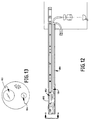
- FIGS. 12 and 13 which show an embodiment 180 of the invention in which an IR endoscope 182 and a visible endoscope 184 are resident in a common tube 186 such that they are coaxially aligned to provide overlapping views of common fields representing IR images and visible images.
- the overlapping views would, of course, contain common subject matter that is substantially coextensive.
- the visible channel may be made substantially smaller in diameter than the IR channel so that the two may still be used with standard sized cannula up to about 15 mm.
- the lenses of the system may be fabricated of ZnSe, ZnSu, Irtran I and II, and CaFl.
Abstract
Description
- This invention relates generally to the field of endoscopic surgery and more particularly to an endoscope imaging system operating at and beyond the two (2) micron region of the spectrum.
- Endoscopic surgery (ES) continues its rapid evolutionary progress as a minimal access surgical technique that reduces patient trauma while not compromising the operating field Operations are performed in a closed physiological environment though the use of specially designed, elongated instruments that are introduced into body cavities via relatively small cannulas (5 to 10 mm or so) and manipulated with visual guidance provided with either direct optical systems or, more recently, video systems. Compared with open surgical procedures, one major advantage of ES flows from the reduction in the severity of parietal wounds even though several cannula are usually used to gain access to the surgical sight. And, there are other advantages including a lessening of postoperative catabolic response, reduction in interior cooling and desiccation due to evaporation, fewer retraction related injuries, fewer adhesions and infections, and shorter hospital stays, along with associated costs.
- ES approaches have commonly been used for laparoscopic surgery and are more frequently being adapted to other procedures such as endoluminal, perivisceral, intra-articular, thoracic, and combinations of these.
- However, if the benefits of ES are to be more fully realized, diagnostic procedures are needed that will permit rapid in situ evaluation of pathology while the surgical procedures are in progress. Presently, this is not possible without significant time delays and the use of relatively complicated x-ray techniques requiring the injection of contrast dyes.
- The negative impact caused by the lack of rapid least-invasive diagnostic procedures can be illustrated by considering one common ES procedure, the laparoscopic cholecystectomy for removal of the gall bladder. As is known, the cystic duct connects the gall bladder to the common bile duct which, in turn, leads to the duodenum. During a laparoscopic cholecystectomy, a diseased gall bladder is excised and removed from the body. In 3-5% of patients with diseased gall bladders, stones are not only present in the gall bladder but are also present in the cystic duct or in the vicinity of the sphincter connecting the cystic duct with the common bile duct. Retained stones present in the sphincter may cause post-operative discomfort to the patient and/or require further surgical intervention.
- In the current art, this discomfort may be avoided by performing a cholangiogram during the cholecystectomy. To accomplish this, a fluoroscope is used to visualize any stones present. If a stone is observed from the cholangiogram, a secondary procedure is conducted in which a slit is made through the cystic duct. A flexible endoscope is then passed through this slit to observe the retained stones. A working channel within the flexible endoscope is equipped with a grasping forceps to remove any stones found. The flexible endoscope is of small enough diameter (∼2mm) to allow entrance into the 6mm diameter cystic duct.
- This secondary procedure has the disadvantage that it is very time-consuming and expensive because the cholecystectomy must be interrupted to bring in the fluoroscope and technician. Also, it is not preferred to expose the operating room personnel to the necessary radiation to conduct the fluoroscopy. In fact, in some 80% of the currently administered laparoscopic cholecystectomies, the cholangiogram is omitted, and the patient is at risk of having retained stones in the cystic duct.
- Clearly, this and similar procedures require an alternate diagnostic tool for visualizing stones or other abnormalities while ES procedures are being conducted, and it is a primary object to this invention to provide endoscopic apparatus and methods by which such diagnoses may be conducted.
- While infrared radiation has been used in the medical field for thermotreatment and other purposes, it appears to have never been used for purposes of diagnosis as advocated hereinafter. Examples of its use from the patent literature are the following:
- US-A-4 122 853 discussed a means for treatment using an infrared laser beam, There is no discussion of means for viewing an IR-emitting object;
- US-A-4 945 409 and US-A-4 951 133 discuss miniature cameras which can be used as an endoscope in the UV, Visible, and IR. A filter from a light source rotates to choose the proper wavelength region. The IR region is confined to near IR less than one (1) µm, and there is no discussion regarding self-emission of the body in the mid-IR. Similarly, the Japanese patents are confined to near-IR wavelengths less than 1.2 µm and only to objects that are illuminated by an external source;
- US-A-4 418 689 describes an endoscope used with a laser. There is no discussion of an endoscope used in the infrared;
- US-A-4 786 813 describes a system for detecting fluorescence of an object. The device is limited to wavelengths less than 0.7 µm and only emissions stimulated by external excitation;
- US-A-4 872 458 describes a thermotherapy device inserted through a conventional visible light flexible or rigid endoscope. In this patent, a heat source generating far-infrared radiation is used for treatment. There is no attempt at visualizing the infrared energy through the endoscope; and
- US-A-5 147 354 describes a fiber optic Ho:Yag laser delivery system that can be inserted through an operating channel of a conventional endoscope. Again, there is no attempt to visualize infrared energy.
-
DE 94 04 312 U describes an endoscope imaging system according to the first part ofclaim 1. There is no discussion regarding self-emission of the body. -
- Consequently, in addition to the primary purpose of the invention, it is an important purpose to provide an endoscope for visualizing interior body structures by providing visible encoded images formed from their infrared emissions.
- The invention also seeks to provide endoscopic systems by which encoded images from infrared emissions from interior body structures can be observed along with images formed from visible light over the same region of interest so that diagnoses may be made via the infrared images and endosurgical procedures performed via the visible images.
- The present invention also seeks to provide endoscopic systems in which encoded infrared images and visible light images can be aligned in optical registration for endodiagnostic and endosurgical procedures.
- The present invention also seeks to provide a means for the use of infrared endodiagnostic procedures for the study of the relationships among infrared images, tissue, and interior body structures to provide a basis for distinguishing normal form abnormal.
- The present invention also seeks to provide an endodiagnostic procedure for detecting the presence of residual stones during and endocholecystectomy.
- Accordingly, this invention provides an endoscope imaging system for use in diagnostic and surgical applications; the system comprises a visible endoscope for forming images from visible light from interior body structures, an infrared endoscope and an image-forming device for visually displaying the visible images from the visible and infrared endoscopes. The endoscope imaging system of the invention is characterized in that the infrared endoscope images infrared emissions within the range including 2 to 14 µm from interior body structures of interest, these bodies being substantially the same as those of interest in the visible images; and is also characterized in that the image-forming device is capable of visually displaying the infrared and visible images so that they may be visually compared for diagnostic and surgical purposes.
- Hereinafter, endodiagnostic apparatus, systems, and methods are described by which infrared emissions from interior body structures may be visualized in the form of encoded images to permit differentiation between normal and abnormal processes. The encoded infrared images may be used along with other images from the visible spectrum to serve as an adjunct in the performance of endosurgical procedures by permitting contemporaneous endodiagnosis and are particularly efficacious for interoperatiye diagnosis during laproscopic surgerical procedures such as endoscopic cholecystectomy where the common bile duct requires exploration for the presence of residual stones.
- The present system can permit information about the normalcy of a visualized site to be encoded in the form of gray scale or colored images to permit differential diagnosis. When infrared images generated by the present system are presented aside of images from radiation from the visible spectrum, pathology may be marked for later surgical procedures in the visual channel.
- In both the infrared and visual channels of the present system, standard NTSC or PAL video signals may be generated for display on video monitors and may be recorded for permanent records.
- The endoscope imaging system of the invention may be provided with means for irrigating at least a portion of an interior body structure of interest with a cooling solution to promote thermal contrast within this portion. This form of the invention permits visualization of residual stones in the common bile duct during endoscopic cholecystectomy by thermal perturbation by cooling with sterile saline or Ringer's solution to cause a general depression in the temperature of the site of interest while continuously imaging with the IR endoscope. As the perturbed area proceeds toward thermal equilibrium with the surrounding body tissue temperature, any retained stones can be visualized because the rate at which they approach thermal equilibrium differs from that of the cystic duct itself.
- In the present system, both the IR diagnostic channel and visible channel may be mounted substantially coaxially in a single tube for alignment purposes, which may include compensation for parallax effects.
- In addition to its usefulness in the diagnosis of residual stones, the system of the invention is also useful for the detection and identification of abdominal fluid sacs or tumors, highly oxygenated or vascular tumors, blood vessels, and cartilage necrosis in body joints.
The structure and operation of the system of the invention will now be described in connection with the drawings in which unique reference numerals have been used throughout for each part and wherein: - Fig 1 is a diagrammatic perspective of an imaging system of the invention showing infrared and visible radiation endoscopic apparatus for providing encoded images from infrared emissions next to corresponding visible images of substantially the same field of interest;
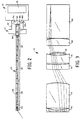
- Fig 2 is a side-elevational view of the infrared endoscope of Fig 1 with parts shown diagrammatically;
- Fig 3 is an enlarged, side-elevational view of the objective system of the infrared endoscope of Fig 2;
- Fig 4 is an enlarged, side-elevational view of one of the relay systems comprising the infrared endoscope of Fig 2;
- Fig 5 is an enlarged, side-elevational view of the coupler lens and infrared camera of the infrared endoscope of Fig 2;
- Fig 6 is an enlarged, side-elevational view of the coupler lens of Fig 5 shown in combination with the infrared camera of the inventive endoscopic system;
- Fig 7 is an enlarged, diagrammatic, side-elevational view of the visible light endoscope of the system of Fig 1;
- Fig 8 is a graph showing the infrared radiant emissions from bodies at 98.6°F and 68°F, along with the difference in IR emissions between them;
- Fig 9 is a graph illustrating the principle of a differential thermal relaxation method used in practicing one aspect of the invention;
- Fig 10 is a representation of an infrared image of the sort that may be obtained utilizing the invention;
- Fig 11 is an alternate embodiment of infrared endoscope according to the invention;
- Fig 12 is another embodiment of the invention in which the infrared and visible endoscopes have been combined for alignment purposes adjacent one another in one tube; and
- Fig 13 is a front-elevational view of the endoscope of Fig 12 looking along the optical axis as indicated by the line A-A.
-
- The present invention relates to endodiagnostic apparatus and methods by which infrared emissions from interior body structures may be visualized in the form of encoded images to permit differentiation between normal and abnormal processes. The encoded infrared images may be used along with other images from the visible spectrum to serve as an adjunct in the performance of endosurgical procedures by permitting contemporaneous endodiagnosis and are particularly efficacious for interoperative diagnosis during laproscopic surgerical procedures such as endoscopic cholecystectomy, where the common bile duct requires exploration for the presence of residual stones. The various embodiments of the invention are based on the recognition that significant signal levels may be derived from emissions from interior body structures in the spectral region in the range including 2 to 14 microns, and that these emissions may be selectively altered using thermal relaxation techniques to enhance the thermal contrast between normal and abnormal processes.
- One preferred embodiment of the invention, designated generally as the
system 20, is shown in use Fig 1 for performing abdominal diagnostic and/or surgical procedures on apatient 19 atop of an operating table 18.System 20 comprises an infrared (IR)endoscopic imager 22 and a visibleendoscopic imager 24.IR imager 22 comprises anIR endoscope 23 and anIR video camera 25, andvisible imager 24 comprises avisible endoscope 27 and avisible video camera 29. -
IR video camera 25 is connected to avideo controller 26 for generating standard NTSC or PAL video signals, and the video controller transmits such standard video signals to avideo monitor 28 for displaying images carried on the standard video signals. -
Visible video camera 29, which may comprise a CCD or vidicon detector or the like, generates a video signal, also in standard video formats, to avisible signal controller 30 which, in turn, transmits it to avideo monitor 32 to display images carried via visible video signal. The video signal processing components of the invention may be of well-known conventional design. - Illumination for the
visible endoscope 27 is provided by way of a visible light source andcontroller 34. Preferably, visible light is conducted via fiber optic cables in a manner to be more fully described hereinafter -
IR imager 22 andvisible imager 24 are each carried on well-known articulable, pneumatically based and controlledrobotic arms controller 40 to permit the user to position and support the endoscopes as required.Robotic arms Arms arms - In this connection, video monitors 28 and 32 may also be mounted on articulated arms (not shown) of the type that are fastened to a wall so that the monitors may be conveniently moved for optimal viewing conditions. Also, it will be understood that each monitor may display both IR and visible images by way of well-known techniques for splitting screens.
- Reference in now made to Fig. 2, which shows various components comprising
IR imager 22. As can be seen there, theIR endoscope 23 comprises andobjective lens 44 for collecting radiation emitted from an object of interest and forming a real image of it, three identical relay sections, 46, 48, and 50, for transferring the real image to an intermediate image plane located near the endoscope's proximal end, and acoupler lens 52 for forming an image of the intermediate image on anIR detector 53. -
IR video camera 25, which includesIR detector 53, is mechanically linked and optically registered withIR endoscope 23 via anadapter 42 that also serves as a warm stop as a consequence of having integrated features for that purpose as will subsequently be explained. -
Camera 25 also includes acold stop 54 for excluding unwanted stray thermal radiation that may otherwise degrade the quality of the IR image by lowering the signal-to-noise ratio of the system. - In this embodiment, all of the elements of the optical train are refractive elements made of Germanium. The elements of objective 44 and relay sections, 46, 48, and 50, are mounted in a well-known manner, in an
elongated tube 58 of appropriate length, and the elements comprising the coupler lens are mounted, again in a well-known manner in asleeve 60 that fits into an appropriately through hole bored inadapter 42.Tube 58 is affixed tosleeve 60, andadapter 42 slides into and is fastened in place in anothersleeve 62 that extends forwardly ofcamera 25 and is adapted to receiveadapter 42 and establish its position with respect toIR detector 53 andcold stop 54. - The IR endoscope has an overall track length of 461.73 mm, its semi-field angle is 34°, its working f/# is 5.72, and the diameter of
tube 58 is 10mm so thatIR endoscope 23 will fit in standard cannula openings. - As best seen in Fig. 3, objective 44 comprises seven elements, a
negative meniscus 70, a thick positive double convex element 72, apositive element 74, anegative element 76, apositive meniscus 78, apositive element 80, and a slightlypositive rod lens 82. The surfaces themselves are 3 through 16, respectively, in following Table I. - Reference is now made to Fig. 4, which shows a typical relay section of the invention. All of the elements of each relay are identical to those shown in Fig. 4. Three relays are used to achieve the desired length, and an odd number of relays provide an upright image in the intermediate plane, although any number can be used with image orientation handled by proper compensation with camera orientation or other well-known means such as a reversal mirror.
- As can be seen in Fig. 4, a typical relay section consists of a piano
convex element 86, ameniscus 88, arod 90, a planoconvex element 92, aconvex plano element 94, arod 96, ameniscus 98 and aconvex plano element 100. It will be appreciated that the relay sections are symmetrical about the aperture stop ofIR endoscope 23, which is betweenelements real entrance aperture 102 located in the rearcurved surface 104 ofadapter 42. This is located just before IR detector 53 (See Fig. 2). The aperture stop could also be any other appropriate material coated with gold. -
Aperture 102 is located in this manner inadapter 42, which in part serves as a warm stop, at the conjugate of the IR endoscope aperture stop so that it will present the smallest opening for the entry of stray thermal radiation into the IR detection system ofcamera 25. The various surfaces of the elements of a typical relay are set forth in Table I below as 16 through 31. - Reference is now made to Fig. 5, which shows the elements of
video coupling lens 52. The intermediate image plane is shown at the circlednumeral 62.Lens 52 itself comprisesnegative element 110,positive element 112, thick negative element 114,positive element 116, and finallyimage 118, which is whereIR detector 53 is resident. The following table lists the constructional data for theIR endoscope 23 where dimensions are in mm. In this table, surfaces 31 through 60 simply repeat the constructional data of surfaces 16 through 31 for a typical relay section as shown in Fig. 4.Surface Radius Thickness Material Diameter OBJ Infinity 50 72.02901 1 Infinity 0.25 SAPPHIRE 7 2 Infinity 0.2 7 3 57.58571 0.3987758 GERMANIUM 7 4 9.425214 0.5789028 7 5 88.87686 7.627548 GERMANIUM 7 6 -15.36183 3.957111 7 7 38.17246 1.559314 GERMANIUM 7 8 47.898 0.3581245 7 9 146.2148 2.402521 GERMANIUM 7 10 15.72048 0.4595021 7 11 -13.73784 0.3845466 GERMANIUM 7 12 -6.854572 2.022597 7 13 855.4531 2.067545 GERMANIUM 7 14 -21.05445 0.07877675 7 15 6793.881 10.0609 GERMANIUM 7 16 Infinity 12.2791 GERMANIUM 7 17 -21.67682 0.2 7 18 55.27044 1.082979 GERMANIUM 7 19 21.05387 1.347465 7 20 Infinity 45 GERMANIUM 7 21 Infinity 0 7 22 Infinity 2 GERMANIUM 7 23 -50.7869 0.2 7 24 50.7869 2 GERMANIUM 7 25 Infinity 0 7 26 Infinity 45 GERMANIUM 7 27 Infinity 1.347465 7 28 -21.05387 1.082979 GERMANIUM 7 29 -55.27044 0.2 7 30 21.67682 12.2791 GERMANIUM 7 31 Infinity 12.2791 GERMANIUM 7 32 -21.67682 0.2 7 33 55.27044 1.082979 GERMANIUM 7 34 21.05387 1.347465 7 35 Infinity 45 GERMANIUM 7 36 Infinity 0 7 37 Infinity 2 GERMANIUM 7 38 -50.7869 0.2 7 39 50.7869 2 GERMANIUM 7 40 Infinity 0 7 41 Infinity 45 GERMANIUM 7 42 Infinity 1.347465 7 43 -21.05387 1.082979 GERMANIUM 7 44 -55.27044 0.2 7 45 21.67682 12.2791 GERMANIUM 7 46 Infinity 12.2791 GERMANIUM 7 47 -21.67682 0.2 7 48 55.27044 1.082979 GERMANIUM 7 49 21.05387 1.347465 7 50 Infinity 45 GERMANIUM 7 51 Infinity 0 7 52 Infinity 2 GERMANIUM 7 53 -50.7869 0.2 7 54 50.7869 2 GERMANIUM 7 55 Infinity 0 7 56 Infinity 45 GERMANIUM 7 57 Infinity 1.347465 7 58 -21.05387 1.082979 GERMANIUM 7 59 -55.27044 0.2 7 60 21.67682 5 GERMANIUM 7 61 53.0202 7.190098 GERMANIUM 7 62 -1181.617 20 GERMANIUM 7 63 100 4 7 64 220.3955 35.78447 GERMANIUM 12 65 -65.86031 4 12 66 39.62417 2 GERMANIUM 12 67 59.62065 50 12 68 Infinity 0 12.84649 - Reference is now made to Fig. 6 which shows in
greater detail adapter 42 with its integral warm stop features along withdetector 53 andIR video camera 25. As mentioned previously, real (physical)aperture 102 is physically positioned at the image of the aperture stop ofIR endoscope 23 and, as such, operates to limit the amount of stray or unwanted thermal radiation that can enter the detection system ofcamera 25. To further deal with the elimination of stray thermal radiation,camera 25 is provided withcold stop 54 for rejecting stray thermal radiation that might enter the detection system and cause signal degradation. Therefore, the rear surface ofadapter 42 is shaped to reflectdetector 53 back onto itself so that any stray radiation bouncing around in the detector cavity that finds its way into the field of view ofdetector 53, as defined in conjunction withaperture 102, is either directly absorbed bycold stop 54 or absorbed by it after one or more reflections as an image back ontocold stop 54. Perferably,detector 53 is placed in a plane that intersects the optical axis at the center of curvature ofsurface 104. - If a warm stop is not to be used, the field of view and f/# of the camera should be exactly matched with that of the IR endoscope, within tolerances, so that only wanted radiation is collected by the camera, and any stray radiation is directly absorbed by the camera cold stop. Here, the cold stop would be at the aperture stop.
- It is to be noted that the above constructional data has been optimized for image quality at 5 microns but, because of the low chromatic dispersion and flat index of refraction profile for germanium, the image quality over the region from 2 to 14 µm will likewise be acceptable so that the inventive IR endoscope is useable over this extended range.
-
IR video camera 25 is to be as light weight as possible, and for this purpose is provided with only apreamplifier 56 with most of the signal amplification and control taking place in the distantly locatedcontroller 26. - One IR video camera and controller which has been found acceptable is marketed by Amber Corporation, a Raytheon Company, of Goleta, Califormia, United States of America, under the
trade name RADIANCE 1. This camera has an indium antimonide (InSb) detector with 256 x 256 picture elements and a spectral bandpass of from 3 to 5 µm. - Reference is now made to Fig 7 which shows the
visible endoscope 24. It is seen to comprise an objective which includes two symmetrically arranged piano convex elements, 120 and 122, respectively, which form an image onto or near the end of a coherentfiber optic bundle 124 which transfers the image to the proximal end of the endoscope where it is imaged by a video coupler lens onto aCCD 130. The video coupler lens comprises asinglet 126 followed by adoublet 128. All of the elements ofvisible endoscope 24 are of well-known design. - Illumination is by way of a
fiber bundle 132 which accepts visible light from source andcontroller 34 and directs it along side the viewing channel toward the distal end for rendering internal body structures visible. - Along side the illumination system, or coaxial with it, is an
irrigation channel 134 that may be used to conduct cooling solutions to the internal site being observed for purposes of providing enhanced thermal contrast to those regions in a manner to be described. - The endoscope imaging system of the invention, thus structured, permits the visualization of otherwise invisible features of internal body structures through the expediency of detecting radiation they emit in the infrared region of the spectrum within the range between 2 and 14 µm. If one looks at Fig. 8, it can be seen that the human body considered as a black body at 37.4°C (98.6°F) (curve 150) has a radiation curve which emits from about 2 to 20 µm with most emissions occurring between about 4 to 15 µm. Consequently, this range of emitted energy has been found sufficient for imaging purposes even at the scale of endoscopes. Moreover, it has been observed that even different body structures at the same temperature will image differently because of differences in their thermal emissivities. Consequently, the system of the present invention is capable of mapping the detected IR emissions as images encoded as differences in either gray scale (monochromatic) or colors (from preselected gamuts) for purposes of providing differential diagnoses which are indicative of normal from abnormal. In addition, it has been found that the addition of cooling solutions to a site of interest will suppress the temperature of that site at least temporarily so that its emissions may look somewhat like
curve 152 in Fig. 8, which is for a black body at 20°C (68°F), or room temperature. As a site temporarily cooled to room temperature gradually warms up, i.e., approaches thermal equilibrium with its surroundings, here body temperature, it will do so but at different rates corresponding to the thermal properties of the different structures of which it is composed. Therefore, different amounts of thermal energy will be emitted and can be detected to form images. This phenomenon can be exploited since there will typically be a differential heat emission given off by a region that has been temporarily cooled as evidenced bycurve 154 in Fig. 8, which shows the difference in thermal energy betweencurves - In one particularly important circumstance, the foregoing observations may be beneficially practiced to solve a significant problem that occurs frequently in connection with the removal of gall bladders. As is well-known, the cystic duct connects the gall bladder to the common bile duct which in turn leads to the duodenum. During a laparoscopic cholecystectomy, a diseased gall bladder is excised and removed from the body. In 3-5% of patients with diseased gall bladders, stones are not only present in the gall bladder but are also present in the cystic duct, or in the vicinity of the sphincter connecting the cystic duct with the common bile duct. Retained stones present in this sphincter may cause post-operative discomfort to the patient or require follow-on surgical intervention. In the current art, to avoid this discomfort, a cholangiogram is conducted during the cholecystectomy. The cholangiogram involves the use of a fluoroscope to visualize any stones present. If a stone is observed from the cholangiogram, a secondary procedure is conducted in which a slit is made through the cystic duct. A flexible endoscope is then passed through this slit to observe the retained stones. A working channel within the flexible endoscope is equipped with a grasping forceps to remove any stones found. The flexible endoscope is of small enough diameter (∼2mm) to allow entrance into the 6mm diameter cystic duct.
- This secondary procedure has the disadvantage that it is very time-consuming and expensive to interrupt the cholecystectomy to bring in the fluoroscope and technician. Also, it is not preferred to expose the operating room personnel to the radiation necessary for conducting the fluoroscopy. In fact, in some 80% of the currently administered laparoscopic cholecystectomies, the cholangiogram is omitted and the patient is at risk of having retained stones in the cystic duct and associated complications.
- In the method of the present invention, diagnosing retained stones in the cystic duct is accomplished by using infrared laparoscopy. The usual visual laparoscope may be temporarily replaced by an infrared laparoscope having approximately the same diameter so that it can be positioned through the same cannula as the visual laparoscope or the IR laparoscope may have two optical channels, one to provide an image using scattered visible illumination and one to provide an image using IR self-emitted from the body. In an alternate embodiment, a single optical channel may be used to provide both visible and IR images with the two separately proximally using a beamsplitter. No operating channels are used in the preferred embodiment since it is preferable to obtain greater parallax by using an auxiliary operating channel (not shown)
- The optical channel containing the visible light forming optics uses conventional lenses such as those present in commercial instruments made by many companies including Circon/ACMI, Storz, Wolf, and others. The visible light optical channel uses a conventional video sensor also available through the foregoing companies. The optical channel containing the infrared light forming optics uses transparent materials in the infrared portion of the spectrum. The IR light optical channel may use one of two types of infrared video sensor. The first type (indium antimonide) has relatively high resolution and is most sensitive at about 5 µm. A second type, HgCdTe, has relatively poor resolution but is sensitive in the 8-12 µm range which is near the peak black body emission curve corresponding to the human body. Also, and preferably, this method uses two separate endoscopes of the type described hereinabove.
- The principal by which the IR laparoscope operates in this instance is by differential thermal relaxation. The area of interest is flushed with roomtemperature sterile saline or Ringer's solution. Upon contact with the area of interest (which would include to general area of the cystic duct and sphincter to the common bile duct), an immediate cooling of the flush site will take place. It should be noted that this irrigation may also be by any commonly used sterile fluid dispenser wand made by companies such as C.R. Bard, Johnson & Johnson, and U.S. Surgical Corporation. This room temperature flush provides a temperature differential of approximately 13.9°C (25 degrees Fahrenheit) compared to surrounding body-temperature tissue. As the area warms back to the surrounding tissue temperature, any retained stones can be visualized because their temperature warms at a different rate compared to the cystic duct itself. This is illustrated with reference to Fig. 9 where
curves - As time progresses the contrast between the retained stones and the cystic duct reaches a maximum (see again Fig. 9) and then declines as both the retained stones and cystic duct relax back to body temperature. In addition to the diagnosis of retained stones in the cystic duct, there are other endoscopic procedures that can be improved by a similar infrared technique as described above. These include: diagnosis of fluid sacs or tumors in the abdominal area and diagnosis of highly oxygenated or vascular tumors. In addition, diagnosis of cartilage necrosis in the joints of the body also appears possible.
- Fig. 10 illustrates how such an infrared image may appear. It shows that instruments, such as clamps may be used to identify or mark abnormal sites in the IR image which then can more easily be operated on via the visible image.
- An alternate version of an IR endoscope suitable for practicing the invention is shown in Fig. 11. This version which is designated generally at 159 consists of a germanium objective lens 160, a relay consisting of
germanium lenses video coupler lens 166, and a warm stop/adapter 168 designed similar in principle to the one described hereinabove. - The constructional data for
IR endoscope 159, which includes aspheric surfaces, is given as follows where the circled numerals in Fig. 11 correspond to surfaces called out in the tabular data below:GENERAL LENS DATA: Surfaces 13 Stop 6 System Aperture Entrance Pupil Diameter Ray aiming On Pupil shift = 0 Gaussian Factor 0.000000 Eff. Focal Len. 6.61067 Total Track 144.16 Image Space F/# 9.72158 Working F/# 10.787 Obj. Space N.A. 0.0185359 Stop Radius -0.35032 Parax. Ima. Hgt. 5.00554 Parax. Mag. -0.404643 Entr. Pup. Dia. 0.68 Entr. Pup. Pos. -6.66032 Exit Pupil Dia. 2.24468 Exit Pupil Pos. -22.7945 Maximum Field 34 Primary Wave 4.000000 Lens Units Millimeters Angular Mag. 0.302939 Coeff on r 14 0 Coeff on r 16 0 Surface 3STANDARD Aperture Circular Aperture Minimum Radius 0 Maximum Radius 3.6 Surface 4 EVENASPH Coeff on r 2 -5.8285e-005 Coeff on r 4 2.2923e-007 Coeff on r 6 -1.5706e-009 Coeff on r 8 0 Coeff on r 100 Coeff on r 12 0 Coeff on r 14 0 Coeff on r 16 0 Surface 5STANDARD Surface STO STANDARD Surface 7 STANDARD Surface 8 EVENASPH Coeff on r 25.8285e-005 Coeff on r 4 -2.2923e-007 Coeff on r 6 1.5706e-009 Coeff on r 8 0 Coeff on r 100 Coeff on r 12 0 Coeff on r 14 0 Coeff on r 16 0 Surface 9STANDARD Surface 10 STANDARD Surface 11 STANDARD Surface 12 STANDARD Aperture Circular Aperture Minimum Radius 0 Maximum Radius 2.2 Surface IMA STANDARD embodiment 180 of the invention in which anIR endoscope 182 and avisible endoscope 184 are resident in acommon tube 186 such that they are coaxially aligned to provide overlapping views of common fields representing IR images and visible images. The overlapping views would, of course, contain common subject matter that is substantially coextensive. Here, the visible channel may be made substantially smaller in diameter than the IR channel so that the two may still be used with standard sized cannula up to about 15 mm. - Those skilled in the art may make other changes to the invention. Aside from medical applications, it would be possible in appropriate circumstances to use the system of the invention for industrial applications. Moreover, it will also be appreciated by those skilled in the art that the lenses of the system may be fabricated of ZnSe, ZnSu, Irtran I and II, and CaFl.
Claims (15)
- An endoscope imaging system (20) for use in diagnostic and surgical applications, the system comprising:a visible endoscope (27) for forming images from visible light from interior body structures, an infrared endoscope (23) and an image-forming device (25, 29) for visually displaying the visible images from the visible and infrared endoscopes (27, 23),the endoscope imaging system (20) being characterized in that:the infrared endoscope (23) images infrared emissions within the range including 2 to 14 µm from interior body structures of interest, these bodies being substantially the same as those of interest in the visible images; and further characterized in that the image-forming device (25, 29) is capable of visually displaying the infrared and visible images so that they may be visually compared for diagnostic and surgical purposes.
- An endoscope imaging system according to claim 1 characterized in that the infra-red endoscope (23) comprisesa refractive objective lens (44) for forming a real image of an interior body structure of interest in an image plane;at least one relay section (46, 48, 50) consisting solely of refracting elements for transferring the real image to form an intermediate image in a conjugate plane located near the proximal end of the infra-red endoscope (23); anda refracting coupling lens (52) for forming a final image of the intermediate image in a detector plane located at the proximal end of the infrared endoscope (23).
- An endoscope imaging system according to claim 2 characterized in that all of the elements of the system are selected from the group consisting of germanium and silicon.
- An endoscope imaging system according to claim 2 or 3 characterized by one or both of (a) a physical stop (54) located near the distal end of the system, the physical stop (54) being composed of a low emissivity material and serving as the aperture stop of the system; and (b) a warm stop (42) located near the proximal end of the system, the warm stop (42) having an aperture therethrough located at the conjugate of the aperture stop of the system.
- An endoscope imaging system according to claim 4 characterized in that the physical stop (54) and/or the warm stop (42) is gold coated.
- An endoscope imaging system according to claim 4 characterized in that the warm stop (42) includes a curved surface that is concave with respect to the detector plane.
- An endoscope imaging system according to any one of the preceding claims characterized by an infrared video camera (25) having a cooled infrared imaging detector located at the detector plane.
- An endoscope imaging system according to claim 7 characterized by a coupling adapter (42) for mechanically linking the camera (25) to the proximal end of the coupler lens, this coupling adapter (42) serving as a warm stop for the system.
- An endoscope imaging system according to claim 8 characterized in that the camera (25) further includes a focal plane and in that the detector is reimaged back onto itself by the warm stop.
- An endoscope imaging system according to any one of the preceding claims characterized by articulable means (36, 38) for supporting and positioning the infrared (23) and visible (27) endoscopes so that they may be aimed at substantially the same interior body structures of interest.
- An endoscope imaging system according to claim 10 characterized in that the infrared (23) and visible (27) endoscopes comprise physically separate endoscopes that can be aimed at substantially the same interior body structures of interest from different perspectives.
- An endoscope imaging system according to any one of the preceding claims characterized by means for marking preselected sites from within the infrared image of the interior body structures of interest such that the preselected sites can be seen in the visible image of the same preselected site.
- An endoscope imaging system according to any one of the preceding claims characterized by means (134) for irrigating at least a portion of an interior body structure of interest with a cooling solution to promote thermal contrast within this portion.
- An endoscope imaging system (180) according to any one of the preceding claims characterized in that the infrared (182) and visible (184) endoscopes reside in a common tube (186) for alignment purposes.
- An endoscope imaging system according to claim 14 characterized in that the infrared (182) and visible (184) endoscopes are compensated for parallax.
Applications Claiming Priority (3)
| Application Number | Priority Date | Filing Date | Title |
|---|---|---|---|
| US08/421,949 US5711755A (en) | 1995-04-14 | 1995-04-14 | Endoscopic diagnostic systems and associated methods employing infrared radiation |
| US421949 | 1995-04-14 | ||
| PCT/US1996/004289 WO1996032052A1 (en) | 1995-04-14 | 1996-04-01 | Endoscopic diagnostic systems and associated methods employing infrared radiation |
Publications (3)
| Publication Number | Publication Date |
|---|---|
| EP0820250A1 EP0820250A1 (en) | 1998-01-28 |
| EP0820250A4 EP0820250A4 (en) | 1998-06-24 |
| EP0820250B1 true EP0820250B1 (en) | 2003-09-17 |
Family
ID=23672755
Family Applications (1)
| Application Number | Title | Priority Date | Filing Date |
|---|---|---|---|
| EP96912496A Expired - Lifetime EP0820250B1 (en) | 1995-04-14 | 1996-04-01 | Endoscopic diagnostic system employing infrared radiation |
Country Status (4)
| Country | Link |
|---|---|
| US (3) | US5711755A (en) |
| EP (1) | EP0820250B1 (en) |
| DE (1) | DE69630026T2 (en) |
| WO (1) | WO1996032052A1 (en) |
Cited By (3)
| Publication number | Priority date | Publication date | Assignee | Title |
|---|---|---|---|---|
| US7312454B2 (en) | 2003-07-16 | 2007-12-25 | The Boeing Company | Non-destructive infrared inspection device |
| DE102014115738A1 (en) | 2014-10-29 | 2016-05-19 | Karl Storz Gmbh & Co. Kg | endoscope |
| US11330968B2 (en) * | 2018-04-26 | 2022-05-17 | avateramedical GmBH | Sterile endoscope sheath |
Families Citing this family (56)
| Publication number | Priority date | Publication date | Assignee | Title |
|---|---|---|---|---|
| JP3865489B2 (en) * | 1997-11-27 | 2007-01-10 | 株式会社町田製作所 | Rigid endoscope |
| AU6417599A (en) | 1998-10-08 | 2000-04-26 | University Of Kentucky Research Foundation, The | Methods and apparatus for (in vivo) identification and characterization of vulnerable atherosclerotic plaques |
| US6178346B1 (en) * | 1998-10-23 | 2001-01-23 | David C. Amundson | Infrared endoscopic imaging in a liquid with suspended particles: method and apparatus |
| JP2000137172A (en) * | 1998-10-29 | 2000-05-16 | Olympus Optical Co Ltd | Image pickup device |
| US6652452B1 (en) | 1999-10-25 | 2003-11-25 | Advanced Medical Electronics Corporation | Infrared endoscope with sensor array at the distal tip |
| US6450949B1 (en) * | 2000-06-30 | 2002-09-17 | Inner Vision Imaging, Inc. | Endoscope |
| US6530882B1 (en) * | 2000-06-30 | 2003-03-11 | Inner Vision Imaging, L.L.C. | Endoscope having microscopic and macroscopic magnification |
| US6678398B2 (en) * | 2000-09-18 | 2004-01-13 | Sti Medical Systems, Inc. | Dual mode real-time screening and rapid full-area, selective-spectral, remote imaging and analysis device and process |
| US6804384B2 (en) | 2001-06-12 | 2004-10-12 | Mclean Hospital Corporation | Color magnetic resonance imaging |
| US8038602B2 (en) * | 2001-10-19 | 2011-10-18 | Visionscope Llc | Portable imaging system employing a miniature endoscope |
| US7158660B2 (en) * | 2002-05-08 | 2007-01-02 | Gee Jr James W | Method and apparatus for detecting structures of interest |
| US8285015B2 (en) | 2002-07-05 | 2012-10-09 | Lawrence Livermore Natioonal Security, LLC | Simultaneous acquisition of differing image types |
| US7684134B2 (en) * | 2003-01-21 | 2010-03-23 | The General Hospital Corporation | Microscope objectives |
| US7535002B2 (en) | 2004-12-03 | 2009-05-19 | Fluke Corporation | Camera with visible light and infrared image blending |
| US7538326B2 (en) * | 2004-12-03 | 2009-05-26 | Fluke Corporation | Visible light and IR combined image camera with a laser pointer |
| US8531562B2 (en) * | 2004-12-03 | 2013-09-10 | Fluke Corporation | Visible light and IR combined image camera with a laser pointer |
| US7438411B2 (en) * | 2005-05-07 | 2008-10-21 | Nanospectra Biosciences, Inc. | Plasmon resonant based eye protection |
| US7570438B2 (en) * | 2005-10-25 | 2009-08-04 | Mckinley Arthur C | Optical apparatus with off-axis direction-of-view |
| US8073535B2 (en) * | 2006-07-19 | 2011-12-06 | Invention Science Fund 1 | Radiant energy derived temperature(s) |
| US20080071144A1 (en) * | 2006-09-15 | 2008-03-20 | William Fein | Novel enhanced higher definition endoscope |
| US20080249400A1 (en) * | 2006-10-06 | 2008-10-09 | University Of Rochester Medical Center | Intraoperative Imaging Of Hepatobiliary Structures |
| WO2008154578A1 (en) * | 2007-06-11 | 2008-12-18 | Board Of Regents, The University Of Texas System | Characterization of a near-infrared laparoscopic hyperspectral imaging system |
| US8272134B2 (en) * | 2007-07-04 | 2012-09-25 | Black & Decker Inc. | Power cutter |
| US20090287109A1 (en) * | 2008-05-14 | 2009-11-19 | Searete Llc, A Limited Liability Corporation Of The State Of Delaware | Circulatory monitoring systems and methods |
| US9717896B2 (en) | 2007-12-18 | 2017-08-01 | Gearbox, Llc | Treatment indications informed by a priori implant information |
| US20090287120A1 (en) | 2007-12-18 | 2009-11-19 | Searete Llc, A Limited Liability Corporation Of The State Of Delaware | Circulatory monitoring systems and methods |
| US8636670B2 (en) | 2008-05-13 | 2014-01-28 | The Invention Science Fund I, Llc | Circulatory monitoring systems and methods |
| US9072445B2 (en) * | 2008-01-24 | 2015-07-07 | Lifeguard Surgical Systems Inc. | Common bile duct surgical imaging system |
| US8284046B2 (en) | 2008-08-27 | 2012-10-09 | The Invention Science Fund I, Llc | Health-related signaling via wearable items |
| US8125331B2 (en) | 2008-08-27 | 2012-02-28 | The Invention Science Fund I, Llc | Health-related signaling via wearable items |
| US8130095B2 (en) | 2008-08-27 | 2012-03-06 | The Invention Science Fund I, Llc | Health-related signaling via wearable items |
| US8094009B2 (en) | 2008-08-27 | 2012-01-10 | The Invention Science Fund I, Llc | Health-related signaling via wearable items |
| US8872125B2 (en) | 2009-04-03 | 2014-10-28 | Lawrence Livermore National Security, Llc | Solution-grown crystals for neutron radiation detectors, and methods of solution growth |
| US8461546B2 (en) | 2009-04-03 | 2013-06-11 | Lawrence Livermore National Security, Llc | Compounds for neutron radiation detectors and systems thereof |
| US20100274081A1 (en) * | 2009-04-22 | 2010-10-28 | Tyco Healthcare Group Lp | Visual veress needle assembly |
| FR2949154B1 (en) * | 2009-08-13 | 2011-09-09 | Snecma | DEVICE FOR CONTROLLING PIECES OF AN AIRCRAFT ENGINE BY INFRARED THERMOGRAPHY |
| US8706184B2 (en) * | 2009-10-07 | 2014-04-22 | Intuitive Surgical Operations, Inc. | Methods and apparatus for displaying enhanced imaging data on a clinical image |
| AU2011332014B2 (en) * | 2010-11-27 | 2016-12-22 | Securus Medical Group, Inc. | Ablation and temperature measurement devices |
| CN102100536B (en) * | 2010-12-10 | 2012-11-21 | 广州宝胆医疗器械科技有限公司 | Electronic duodenoscope system with infrared thermal scanning function |
| CN102100527B (en) * | 2010-12-10 | 2012-11-21 | 广州宝胆医疗器械科技有限公司 | Electronic gastroscope system with infrared thermally scanning function |
| CN102100544A (en) * | 2010-12-10 | 2011-06-22 | 广州宝胆医疗器械科技有限公司 | Cholecystoscope system with infrared heat-scanning function |
| WO2012142482A1 (en) * | 2011-04-13 | 2012-10-18 | Curax, Llc | Multi-function cannulated surgical device |
| US9309456B2 (en) | 2011-04-15 | 2016-04-12 | Lawrence Livermore National Security, Llc | Plastic scintillator with effective pulse shape discrimination for neutron and gamma detection |
| WO2012143800A1 (en) * | 2011-04-19 | 2012-10-26 | Yasser Fawzy | Method and device for fluorescence guided surgery to improve intraoperative visualization of biliary tree |
| US9005151B2 (en) | 2011-09-07 | 2015-04-14 | Choon Kee Lee | Thermal apparatus |
| US9121947B2 (en) | 2012-01-23 | 2015-09-01 | Lawrence Livermore National Security, Llc | Stress reduction for pillar filled structures |
| US8580054B2 (en) | 2012-04-04 | 2013-11-12 | Lawrence Livermore National Security, Llc | Melt-castable energetic compounds comprising oxadiazoles and methods of production thereof |
| US20130289362A1 (en) * | 2012-04-30 | 2013-10-31 | Empire Technology Development Llc | Infrared guide stars for endoscopic orienteering |
| US9650564B2 (en) | 2012-05-14 | 2017-05-16 | Lawrence Livermore National Security, Llc | System and plastic scintillator for discrimination of thermal neutron, fast neutron, and gamma radiation |
| WO2014043697A2 (en) | 2012-09-17 | 2014-03-20 | Omniguide, Inc. | Devices and methods for laser surgery |
| US20140139658A1 (en) * | 2012-11-20 | 2014-05-22 | General Electric Company | Remote visual inspection system and method |
| DE102013213247A1 (en) * | 2013-07-05 | 2015-01-08 | Olympus Winter & Ibe Gmbh | Video endoscopy system, coupling device, video endoscope and control device |
| US9274237B2 (en) | 2013-07-26 | 2016-03-01 | Lawrence Livermore National Security, Llc | Lithium-containing scintillators for thermal neutron, fast neutron, and gamma detection |
| WO2016006113A1 (en) * | 2014-07-11 | 2016-01-14 | 株式会社ニコン | Image analysis device, imaging system, surgery assistance system, image analysis method, and image analysis program |
| DE102018110095A1 (en) | 2018-04-26 | 2019-10-31 | avateramedical GmBH | Sterile endoscope cover |
| US11903557B2 (en) | 2019-04-30 | 2024-02-20 | Psip2 Llc | Endoscope for imaging in nonvisible light |
Family Cites Families (31)
| Publication number | Priority date | Publication date | Assignee | Title |
|---|---|---|---|---|
| US4122853A (en) * | 1977-03-14 | 1978-10-31 | Spectra-Med | Infrared laser photocautery device |
| DE2950317A1 (en) * | 1979-12-14 | 1981-06-19 | Agfa-Gevaert Ag, 5090 Leverkusen | ELECTROTHERMOGRAPHIC DEVICE |
| DE3169553D1 (en) * | 1980-09-22 | 1985-05-02 | Olympus Optical Co | A laser device for an endoscope |
| US5056525A (en) * | 1984-03-21 | 1991-10-15 | Hafezi Fred F | Process for diagnosing spinal conditions |
| SE455646B (en) * | 1984-10-22 | 1988-07-25 | Radians Innova Ab | FLUORESCENT DEVICE |
| US4783593A (en) * | 1985-12-26 | 1988-11-08 | General Electric Company | Optical system for wide angle IR imager |
| US4820923A (en) * | 1986-06-19 | 1989-04-11 | Santa Barbara Research Center | Uncooled reflective shield for cryogenically-cooled radiation detectors |
| US4817622A (en) * | 1986-07-22 | 1989-04-04 | Carl Pennypacker | Infrared imager for viewing subcutaneous location of vascular structures and method of use |
| US4872458A (en) * | 1986-09-16 | 1989-10-10 | Olympus Optical Co., Ltd. | Thermotherapy apparatus |
| JPS62174713A (en) * | 1987-01-24 | 1987-07-31 | Olympus Optical Co Ltd | Endoscope device |
| JPS62174716A (en) * | 1987-01-24 | 1987-07-31 | Olympus Optical Co Ltd | Endoscope device |
| JPS62174715A (en) * | 1987-01-24 | 1987-07-31 | Olympus Optical Co Ltd | Endoscope device |
| US5177605A (en) * | 1987-04-28 | 1993-01-05 | Olympus Optical Co., Ltd. | Optical system for endoscopes and endoscopes using same |
| US4905082A (en) * | 1987-05-06 | 1990-02-27 | Olympus Optical Co., Ltd. | Rigid video endoscope having a detachable imaging unit |
| JP2643941B2 (en) * | 1987-06-11 | 1997-08-25 | オリンパス光学工業株式会社 | Image processing device for endoscope |
| GB2218875B (en) * | 1988-05-21 | 1992-04-15 | Marconi Gec Ltd | Thermal imager |
| US5147354B1 (en) * | 1988-08-19 | 1997-10-14 | Coherent Inc | Mid-infrared laser endoscope |
| JP2666856B2 (en) * | 1988-10-15 | 1997-10-22 | オリンパス光学工業株式会社 | Light source device for endoscope |
| JPH03182185A (en) * | 1989-12-11 | 1991-08-08 | Fujitsu Ltd | Infrared monitoring system |
| US4995398A (en) * | 1990-04-30 | 1991-02-26 | Turnidge Patrick A | Coronary angiography imaging system |
| US5305759A (en) * | 1990-09-26 | 1994-04-26 | Olympus Optical Co., Ltd. | Examined body interior information observing apparatus by using photo-pulses controlling gains for depths |
| US5293872A (en) * | 1991-04-03 | 1994-03-15 | Alfano Robert R | Method for distinguishing between calcified atherosclerotic tissue and fibrous atherosclerotic tissue or normal cardiovascular tissue using Raman spectroscopy |
| US5417210A (en) * | 1992-05-27 | 1995-05-23 | International Business Machines Corporation | System and method for augmentation of endoscopic surgery |
| US5184601A (en) * | 1991-08-05 | 1993-02-09 | Putman John M | Endoscope stabilizer |
| JPH05228098A (en) * | 1992-02-20 | 1993-09-07 | Asahi Optical Co Ltd | Thermoendoscope |
| US5263110A (en) * | 1992-09-03 | 1993-11-16 | Linvatec Corporation | Imaging endoscope and endoscopic method employing phase conjugate imaging techniques |
| US5423321A (en) * | 1993-02-11 | 1995-06-13 | Fontenot; Mark G. | Detection of anatomic passages using infrared emitting catheter |
| US5596992A (en) * | 1993-06-30 | 1997-01-28 | Sandia Corporation | Multivariate classification of infrared spectra of cell and tissue samples |
| US5790586A (en) * | 1993-09-30 | 1998-08-04 | Amorphous Materials, Inc. | Method and apparatus for simultaneously illuminating, viewing and measuring the temperature of a body |
| DE9404312U1 (en) * | 1994-03-09 | 1994-06-23 | Mira Gmbh | Medical diagnostic tool |
| US5444250A (en) * | 1994-08-15 | 1995-08-22 | Hughes Aircraft Company | Optical warm stop with fresnel type reflective surface |
-
1995
- 1995-04-14 US US08/421,949 patent/US5711755A/en not_active Expired - Lifetime
-
1996
- 1996-04-01 EP EP96912496A patent/EP0820250B1/en not_active Expired - Lifetime
- 1996-04-01 WO PCT/US1996/004289 patent/WO1996032052A1/en active IP Right Grant
- 1996-04-01 DE DE69630026T patent/DE69630026T2/en not_active Expired - Lifetime
-
1997
- 1997-06-23 US US08/880,692 patent/US5944653A/en not_active Expired - Lifetime
- 1997-06-23 US US08/880,686 patent/US5997472A/en not_active Expired - Lifetime
Cited By (4)
| Publication number | Priority date | Publication date | Assignee | Title |
|---|---|---|---|---|
| US7312454B2 (en) | 2003-07-16 | 2007-12-25 | The Boeing Company | Non-destructive infrared inspection device |
| DE102014115738A1 (en) | 2014-10-29 | 2016-05-19 | Karl Storz Gmbh & Co. Kg | endoscope |
| DE102014115738B4 (en) | 2014-10-29 | 2021-07-29 | Karl Storz Se & Co. Kg | Endoscope and endoscopic system |
| US11330968B2 (en) * | 2018-04-26 | 2022-05-17 | avateramedical GmBH | Sterile endoscope sheath |
Also Published As
| Publication number | Publication date |
|---|---|
| DE69630026T2 (en) | 2004-06-24 |
| US5711755A (en) | 1998-01-27 |
| DE69630026D1 (en) | 2003-10-23 |
| WO1996032052A1 (en) | 1996-10-17 |
| EP0820250A1 (en) | 1998-01-28 |
| US5944653A (en) | 1999-08-31 |
| US5997472A (en) | 1999-12-07 |
| EP0820250A4 (en) | 1998-06-24 |
Similar Documents
| Publication | Publication Date | Title |
|---|---|---|
| EP0820250B1 (en) | Endoscopic diagnostic system employing infrared radiation | |
| US5833596A (en) | Endoscope for imaging infrared emissions within the range of 2 to 14 microns | |
| US8480566B2 (en) | Solid state illumination for endoscopy | |
| US6949069B2 (en) | Endoscope | |
| US20160262604A1 (en) | Optical Speculum | |
| US5846185A (en) | High resolution, wide field of view endoscopic viewing system | |
| US5601549A (en) | Medical observing instrument | |
| JP3032214B2 (en) | Surgical microscope | |
| US5406938A (en) | Glare elimination device | |
| JP2989237B2 (en) | Optical device | |
| US5295477A (en) | Endoscopic operating microscope | |
| US5329936A (en) | Portable arthroscope with periscope optics | |
| US5411500A (en) | Portable arthroscope with disposable probe | |
| US20070173688A1 (en) | Laproscope with flexible binocular camera | |
| CA2924274C (en) | Optical speculum | |
| JPH05115425A (en) | Endoscope | |
| IL138632A (en) | Multiple view endoscopes | |
| US9271640B2 (en) | Optical speculum | |
| JP2001161638A (en) | Microscope for operation | |
| Leonhard et al. | The endoscope, endoscopic equipment and instrumentation | |
| JPH09248276A (en) | Sight line variable hard mirror device | |
| US7684134B2 (en) | Microscope objectives | |
| Xiang et al. | The optical design of stereo endoscope | |
| Pankratov et al. | Endoscopy of the middle ear | |
| Sekiya et al. | Development of a dual-view endoscope system |
Legal Events
| Date | Code | Title | Description |
|---|---|---|---|
| PUAI | Public reference made under article 153(3) epc to a published international application that has entered the european phase |
Free format text: ORIGINAL CODE: 0009012 |
|
| 17P | Request for examination filed |
Effective date: 19971006 |
|
| AK | Designated contracting states |
Kind code of ref document: A1 Designated state(s): CH DE FR GB LI NL |
|
| RIN1 | Information on inventor provided before grant (corrected) |
Inventor name: BRUKILACCHIO, THOMAS Inventor name: LEINER, DENNIS, C. Inventor name: BONNELL, LEONARD, J. |
|
| A4 | Supplementary search report drawn up and despatched |
Effective date: 19980511 |
|
| AK | Designated contracting states |
Kind code of ref document: A4 Designated state(s): CH DE FR GB LI NL |
|
| 17Q | First examination report despatched |
Effective date: 20020214 |
|
| GRAH | Despatch of communication of intention to grant a patent |
Free format text: ORIGINAL CODE: EPIDOS IGRA |
|
| RTI1 | Title (correction) |
Free format text: ENDOSCOPIC DIAGNOSTIC SYSTEM EMPLOYING INFRARED RADIATION |
|
| RTI1 | Title (correction) |
Free format text: ENDOSCOPIC DIAGNOSTIC SYSTEM EMPLOYING INFRARED RADIATION |
|
| GRAS | Grant fee paid |
Free format text: ORIGINAL CODE: EPIDOSNIGR3 |
|
| GRAA | (expected) grant |
Free format text: ORIGINAL CODE: 0009210 |
|
| AK | Designated contracting states |
Kind code of ref document: B1 Designated state(s): CH DE FR GB LI NL |
|
| PG25 | Lapsed in a contracting state [announced via postgrant information from national office to epo] |
Ref country code: NL Free format text: LAPSE BECAUSE OF FAILURE TO SUBMIT A TRANSLATION OF THE DESCRIPTION OR TO PAY THE FEE WITHIN THE PRESCRIBED TIME-LIMIT Effective date: 20030917 Ref country code: LI Free format text: LAPSE BECAUSE OF FAILURE TO SUBMIT A TRANSLATION OF THE DESCRIPTION OR TO PAY THE FEE WITHIN THE PRESCRIBED TIME-LIMIT Effective date: 20030917 Ref country code: FR Free format text: LAPSE BECAUSE OF FAILURE TO SUBMIT A TRANSLATION OF THE DESCRIPTION OR TO PAY THE FEE WITHIN THE PRESCRIBED TIME-LIMIT Effective date: 20030917 Ref country code: CH Free format text: LAPSE BECAUSE OF FAILURE TO SUBMIT A TRANSLATION OF THE DESCRIPTION OR TO PAY THE FEE WITHIN THE PRESCRIBED TIME-LIMIT Effective date: 20030917 |
|
| REG | Reference to a national code |
Ref country code: GB Ref legal event code: FG4D |
|
| REG | Reference to a national code |
Ref country code: CH Ref legal event code: EP |
|
| REF | Corresponds to: |
Ref document number: 69630026 Country of ref document: DE Date of ref document: 20031023 Kind code of ref document: P |
|
| NLV1 | Nl: lapsed or annulled due to failure to fulfill the requirements of art. 29p and 29m of the patents act | ||
| REG | Reference to a national code |
Ref country code: CH Ref legal event code: PL |
|
| PLBE | No opposition filed within time limit |
Free format text: ORIGINAL CODE: 0009261 |
|
| STAA | Information on the status of an ep patent application or granted ep patent |
Free format text: STATUS: NO OPPOSITION FILED WITHIN TIME LIMIT |
|
| 26N | No opposition filed |
Effective date: 20040618 |
|
| EN | Fr: translation not filed | ||
| PGFP | Annual fee paid to national office [announced via postgrant information from national office to epo] |
Ref country code: DE Payment date: 20110630 Year of fee payment: 16 |
|
| REG | Reference to a national code |
Ref country code: DE Ref legal event code: R119 Ref document number: 69630026 Country of ref document: DE Effective date: 20121101 |
|
| PGFP | Annual fee paid to national office [announced via postgrant information from national office to epo] |
Ref country code: GB Payment date: 20121024 Year of fee payment: 17 |
|
| GBPC | Gb: european patent ceased through non-payment of renewal fee |
Effective date: 20130401 |
|
| PG25 | Lapsed in a contracting state [announced via postgrant information from national office to epo] |
Ref country code: GB Free format text: LAPSE BECAUSE OF NON-PAYMENT OF DUE FEES Effective date: 20130401 |
|
| PG25 | Lapsed in a contracting state [announced via postgrant information from national office to epo] |
Ref country code: DE Free format text: LAPSE BECAUSE OF NON-PAYMENT OF DUE FEES Effective date: 20121101 |