EP0824928A2 - Tracheostomy tube assemblies - Google Patents
Tracheostomy tube assemblies Download PDFInfo
- Publication number
- EP0824928A2 EP0824928A2 EP97305746A EP97305746A EP0824928A2 EP 0824928 A2 EP0824928 A2 EP 0824928A2 EP 97305746 A EP97305746 A EP 97305746A EP 97305746 A EP97305746 A EP 97305746A EP 0824928 A2 EP0824928 A2 EP 0824928A2
- Authority
- EP
- European Patent Office
- Prior art keywords
- tube
- obturator
- assembly according
- medical tube
- coupling
- Prior art date
- Legal status (The legal status is an assumption and is not a legal conclusion. Google has not performed a legal analysis and makes no representation as to the accuracy of the status listed.)
- Granted
Links
Images

Classifications
-
- A—HUMAN NECESSITIES
- A61—MEDICAL OR VETERINARY SCIENCE; HYGIENE
- A61M—DEVICES FOR INTRODUCING MEDIA INTO, OR ONTO, THE BODY; DEVICES FOR TRANSDUCING BODY MEDIA OR FOR TAKING MEDIA FROM THE BODY; DEVICES FOR PRODUCING OR ENDING SLEEP OR STUPOR
- A61M16/00—Devices for influencing the respiratory system of patients by gas treatment, e.g. mouth-to-mouth respiration; Tracheal tubes
- A61M16/04—Tracheal tubes
- A61M16/0465—Tracheostomy tubes; Devices for performing a tracheostomy; Accessories therefor, e.g. masks, filters
-
- A—HUMAN NECESSITIES
- A61—MEDICAL OR VETERINARY SCIENCE; HYGIENE
- A61M—DEVICES FOR INTRODUCING MEDIA INTO, OR ONTO, THE BODY; DEVICES FOR TRANSDUCING BODY MEDIA OR FOR TAKING MEDIA FROM THE BODY; DEVICES FOR PRODUCING OR ENDING SLEEP OR STUPOR
- A61M16/00—Devices for influencing the respiratory system of patients by gas treatment, e.g. mouth-to-mouth respiration; Tracheal tubes
- A61M16/04—Tracheal tubes
- A61M16/0402—Special features for tracheal tubes not otherwise provided for
- A61M16/0429—Special features for tracheal tubes not otherwise provided for with non-integrated distal obturators
-
- A—HUMAN NECESSITIES
- A61—MEDICAL OR VETERINARY SCIENCE; HYGIENE
- A61M—DEVICES FOR INTRODUCING MEDIA INTO, OR ONTO, THE BODY; DEVICES FOR TRANSDUCING BODY MEDIA OR FOR TAKING MEDIA FROM THE BODY; DEVICES FOR PRODUCING OR ENDING SLEEP OR STUPOR
- A61M16/00—Devices for influencing the respiratory system of patients by gas treatment, e.g. mouth-to-mouth respiration; Tracheal tubes
- A61M16/04—Tracheal tubes
- A61M16/0488—Mouthpieces; Means for guiding, securing or introducing the tubes
- A61M16/0497—Tube stabilizer
Definitions
- This invention relates to medical tube assemblies of the kind comprising a medical tube and an obturator inserted within the tube, the obturator having a patient end projecting from the patient end of the tube to aid insertion of the assembly.
- Tracheostomy tubes are often inserted with the aid of an obturator having a pointed end projecting from the patient end of the tracheostomy tube.
- the tip of the obturator helps separate tissue, enabling smooth entry of the tube.
- the obturator also helps stiffen the tube and prevents ingress of tissue into the tube, which could cause blockage. Examples of tracheostomy obturators are described in US4246897, US5222487 and GB2224213. The obturator is pushed into the tracheal tube to its full extent, as limited by a flange abutting the patient end connector on the tracheal tube.
- the surgeon has to grip the machine end of the obturator and the tube in order to hold the obturator in place and prevent it being pushed rearwardly out of the tube during insertion. Any displacement of the obturator from its correct position may make insertion of the tube more difficult and, by reducing the smoothness of the patient end of the assembly, may cause trauma to tissue around the stoma. After insertion, the obturator is pulled out of the machine end of the tube. Obturators are also used to help insertion of other medical tubes.
- a medical tube assembly of the above-specified kind characterised in that the obturator and tube are provided at their machine ends with cooperating surface formations arranged, when engaged, to prevent rearward displacement of the obturator relative to the tube.
- the cooperating surface formations are preferably arranged such that they can be disengaged by twisting the obturator through a small angle relative to the tube.
- the cooperating surface formations may be provided by a resilient catch and a lip.
- the obturator preferably has two resilient catches extending along opposite sides of the tube and engaging respective lips on the tube.
- the tube may have a coupling at its patient end, the surface formation on the obturator being provided by at least one resilient catch that extends along the outside of the connector and engages on a surface formation on the connector.
- the obturator may have a strap of rectangular section extending between its machine end and its patient end. The patient and machine ends of the obturator both preferably have an air passage therethrough.
- the obturator may be moulded from a plastics material.
- the medical tube may be a tracheostomy tube and the patient end of the obturator be pointed, the tube and obturator together providing an air passage extending along the assembly to enable the patient to breath while the assembly is being inserted.
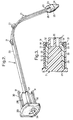
- the assembly comprises a tracheostomy tube 1 and an obturator 2.
- the tube 1 has a conventional shaft 10 of circular section, which is curved or bent to suit the anatomical requirements of the patient.
- the patient end 11 of the shaft 10 is cut square and rounded to be atraumatic.
- the shaft 10 is bonded to a coupling 12 having a female tapered bore 13 shaped to receive a male tapered coupling (not shown) connected to a patient ventilation or anaesthetic circuit.
- the coupling 12 is left open.
- the coupling 12 is of cylindrical shape apart from surface formations provided by two, short undercut lips 14 located diametrically opposite one another at the patient end of the coupling.
- the tube 1 also includes a conventional, adjustable flange 15 of the kind described in GB2227941.
- the flange 15 has a flexible plate 16 to which two semi-circular arms 17 are attached and hinged with one another.
- the arms 17 can be clamped together, to lock the flange 15 at any location along the shaft 10, by means of a bolt 18 on one arm that engages a threaded aperture 19 on the other arm.
- the shaft 10 has an inflatable cuff (not shown) towards its patient end, for sealing with the inside of the trachea; alternative tubes need not include such a cuff.
- the obturator 2 is moulded from a stiff but bendable, resilient plastics material and has a strap 20 of generally rectangular shape extending along the major part of its length, the width of the strap being slightly less than the internal diameter of the shaft 10 of the tube 1.
- the strap 20 is bent at right angles, to the same shape as that of the shaft 10, and has three semicircular projections 21 on its convex side, in the region of the bend, so that the strap is held substantially centrally within the tube 1 in the region of the bend.
- the obturator is provided with a bullet shape nose 23, which is a close fit within the patient end 11 of the tube 1.
- the nose 23 has a pointed tip 24, which, in use, projects from the tube 1 so as to form a pointed continuation of the patient end of the shaft 10.
- a bore 25 extends along the nose 23 from its tip 24 to an opening 26 at its rear end.
- the obturator 2 has an enlarged, cruciform section 28 with a tapered exterior, which is a close friction fit within the coupling 12 of the tube 1.
- a flange 29 extends radially at the machine end of the cruciform section 28 and provides a grip by which the obturator 2 can be inserted and removed from the tube 1.
- Two resilient arms 30 extend forwardly from the flange 29 on opposite sides of the obturator 2. The arms 30 are terminated at their patient end by surface formations in the form of inwardly-directed catches 31 formed by an inclined ramp 32 and a ledge 33.
- the dimensions of the arms 30 are such that, when the flange 29 abuts the machine end of the coupling 12, the arms extend along opposite sides of the coupling 12 with the catches 31 engaging under the lips 14, thereby preventing the obturator 2 being removed from the tube.
- Two vent holes 34 are formed through the flange 29 in alignment with the corners between the cruciform section 28.
- the obturator 2 In use, the obturator 2 is pushed fully into the tube 1 so that the nose 23 projects from the patient end 11 of the tube and so that the catches 31 engage the lips 14 on the coupling 12.
- the flexible nature of the strap 20 enables it to be bent during insertion and removal to conform to the shape of the tube 1, without deforming the tube itself.
- the assembly is inserted in the usual way, the obturator 2 providing a tapered lead into the tracheostomy for the tube 1. Rearward movement of the obturator 2 relative to the tube 1 is prevented by engagement of the catches 31 with the lips 14.
- the patient can breath through the assembly during insertion because of the bore 25 through the nose, the passage between the strap 20 of the obturator 2 and the inside of the tube, and the holes 34 in the flange 29.
- the obturator 2 is removed by gripping the flange 29 and twisting it through about 20° so that the catches 31 come out of alignment with the lips 14 and can be pulled rearwardly along the outside of the coupling 12.
- the coupling 12 can be connected to a ventilation circuit or left open, in the usual way.
- the present invention makes insertion of the assembly easier because there is no need to hold the machine end of the obturator. Also, there is no risk of the obturator being displaced rearwardly during insertion, thereby ensuring that damage to the tissue around the stoma is minimized.
- the provision of the lips on the coupling, at the machine end of the tube do not prevent the tube being connected to conventional couplings. It will be appreciated that the obturator could be locked with the tube against rearward displacement by alternative surface formations on the machine end of the obturator and tube.
- the invention could be used with tubes, other than tracheal tubes, where it is necessary to prevent displacement of an obturator relative to a tube.
Abstract
Description
Claims (9)
- A medical tube assembly comprising a medical tube (1) and an obturator (2) inserted within the tube, the obturator having a patient end (22) projecting from the patient end of the tube (1) to aid insertion of the assembly, characterised in that the obturator (2) and tube (1) are provided at their machine ends with cooperating surface formations (30, 31, 14) arranged, when engaged, to prevent rearward displacement of the obturator (2) relative to the tube (1).
- A medical tube assembly according to Claim 1, characterised in that the cooperating surface formations (30, 31, 14) are arranged such that they can be disengaged by twisting the obturator (2) through a small angle relative to the tube (1).
- A medical tube assembly according to Claim 1 or 2, characterised in that the cooperating surface formations are provided by a resilient catch (30, 31) and a lip (14).
- A medical tube assembly according to Claim 3, characterised in that the obturator (2) has two resilient catches (30, 31) extending along opposite sides of the tube (1) and engaging respective lips (14) on the tube.
- A medical tube assembly according to any one of the preceding claims, characterised in that the tube (1) has a coupling (12) at its machine end, and that the surface formation on the obturator (2) is provided by at least one resilient catch (30, 31) that extends along the outside of the coupling (12) and engages on a surface formation (14) on the coupling.
- A medical tube assembly according to any one of the preceding claims, characterised in that the obturator (2) has a strap (20) of rectangular section extending between its machine end and its patient end .
- A medical tube assembly according to Claim 6, characterised in that the patient end (22) and the machine end of the obturator (2) both have an air passage (25, 26 and 34) therethrough.
- A medical tube assembly according to any one of the preceding claims, characterised in that the obturator (2) is moulded from a plastics material.
- A tracheostomy tube assembly according to any one of the preceding claims wherein the medical tube is a tracheostomy tube (1) and the patient end (22) of the obturator (2) is pointed, characterised in that the tube (1) and obturator (2) together provide an air passage extending along the assembly to enable the patient to breath while the assembly is being inserted.
Applications Claiming Priority (2)
| Application Number | Priority Date | Filing Date | Title |
|---|---|---|---|
| GBGB9617545.0A GB9617545D0 (en) | 1996-08-21 | 1996-08-21 | Medical tube assemblies |
| GB9617545 | 1996-08-21 |
Publications (3)
| Publication Number | Publication Date |
|---|---|
| EP0824928A2 true EP0824928A2 (en) | 1998-02-25 |
| EP0824928A3 EP0824928A3 (en) | 1998-07-22 |
| EP0824928B1 EP0824928B1 (en) | 2002-03-27 |
Family
ID=10798776
Family Applications (1)
| Application Number | Title | Priority Date | Filing Date |
|---|---|---|---|
| EP97305746A Expired - Lifetime EP0824928B1 (en) | 1996-08-21 | 1997-07-30 | Tracheostomy tube assemblies |
Country Status (7)
| Country | Link |
|---|---|
| US (1) | US5928198A (en) |
| EP (1) | EP0824928B1 (en) |
| JP (1) | JP3876057B2 (en) |
| AU (1) | AU725975B2 (en) |
| DE (1) | DE69711298T2 (en) |
| GB (1) | GB9617545D0 (en) |
| ZA (1) | ZA977313B (en) |
Cited By (3)
| Publication number | Priority date | Publication date | Assignee | Title |
|---|---|---|---|---|
| EP1099451A2 (en) * | 1999-11-11 | 2001-05-16 | Smiths Industries Public Limited Company | Tracheostomy tube assemblies and obturators |
| JP2015523188A (en) * | 2012-08-02 | 2015-08-13 | コヴィディエン リミテッド パートナーシップ | Compressible connector for inner cannula |
| WO2022200751A1 (en) * | 2021-03-25 | 2022-09-29 | Smiths Medical International Limited | Obturators and tube assemblies |
Families Citing this family (27)
| Publication number | Priority date | Publication date | Assignee | Title |
|---|---|---|---|---|
| US7699055B2 (en) * | 1997-09-06 | 2010-04-20 | Tracoe Gesellschaft Fur Medizinische Bedarfsgegenstande Mbh | Tracheotomy cannula with shield plate |
| GB9819330D0 (en) * | 1998-09-05 | 1998-10-28 | Smiths Industries Plc | Introducers and tube assemblies |
| GB9908136D0 (en) * | 1999-04-12 | 1999-06-02 | Smiths Industries Plc | Obturators and tube assemblies |
| US6666846B1 (en) * | 1999-11-12 | 2003-12-23 | Edwards Lifesciences Corporation | Medical device introducer and obturator and methods of use |
| US7077841B2 (en) | 2001-03-26 | 2006-07-18 | Curon Medical, Inc. | Systems and methods employing a guidewire for positioning and stabilizing external instruments deployed within the body |
| US7160270B2 (en) * | 2001-03-26 | 2007-01-09 | Curon Medical, Inc. | Systems and methods employing a bite block insert for positioning and stabilizing external instruments deployed within the body |
| GB2383755B (en) * | 2002-01-04 | 2004-02-25 | Future Top Medical Environment | Obturator for use with a laryngeal mask airway |
| AU2003256331A1 (en) * | 2002-06-28 | 2004-01-19 | Cook Critical Care | Introducer sheath |
| WO2004069316A2 (en) * | 2003-02-03 | 2004-08-19 | Cook Critical Care | Tracheostomy tube dilator |
| DE10359220A1 (en) * | 2003-12-17 | 2005-07-28 | Tracoe Medical Gmbh | Tracheostomy |
| US8001969B2 (en) * | 2005-02-07 | 2011-08-23 | Securisyn Medical, Llc | Complete airway stabilization system and method |
| US9814853B2 (en) | 2005-02-07 | 2017-11-14 | Securisyn Medical, Llc | Airway stabilization system |
| US7987851B2 (en) * | 2005-12-27 | 2011-08-02 | Hansa Medical Products, Inc. | Valved fenestrated tracheotomy tube having outer and inner cannulae |
| US7850667B2 (en) * | 2008-06-27 | 2010-12-14 | Tyco Healthcare Group Lp | Low profile instrument access device |
| US20120204867A1 (en) * | 2009-10-15 | 2012-08-16 | Airway Cam Technologies, Inc. | Introducer for Surgical Airway Catheters |
| US8887717B2 (en) * | 2009-10-15 | 2014-11-18 | Airway Cam Technologies, Inc. | Introducer for surgical airway catheters |
| MX2012006598A (en) | 2009-12-23 | 2012-06-19 | Alcon Res Ltd | Ophthalmic valved trocar cannula. |
| US8343106B2 (en) | 2009-12-23 | 2013-01-01 | Alcon Research, Ltd. | Ophthalmic valved trocar vent |
| US9393374B2 (en) | 2013-03-25 | 2016-07-19 | Richard M. Levitan | Introducer for surgical airway catheters |
| WO2014162392A1 (en) * | 2013-04-01 | 2014-10-09 | テルモ株式会社 | Guide wire |
| US9539402B2 (en) * | 2013-06-10 | 2017-01-10 | Guidance Airway Solutions, Llc | Combined laryngo-tracheal anesthetic and stylet device |
| US10046130B2 (en) | 2015-05-21 | 2018-08-14 | Laerdal Medical As | Airway-tube holder |
| USD834185S1 (en) * | 2015-05-21 | 2018-11-20 | Laerdal Medical As | Airway-tube holder |
| GB201511113D0 (en) | 2015-06-24 | 2015-08-05 | Smiths Medical Int Ltd | Tube introducers, assemblies and methods |
| US11219729B2 (en) | 2018-03-21 | 2022-01-11 | Hansa Medical Products, Inc. | Medical device system and method including an endotracheal tube |
| DE102018133449A1 (en) | 2018-12-21 | 2020-06-25 | Tracoe Medical Gmbh | Insertion aid for tracheostomy tubes |
| US20230001121A1 (en) * | 2021-07-01 | 2023-01-05 | Mackenzie McKinney | Securement device for medical tubing |
Citations (4)
| Publication number | Priority date | Publication date | Assignee | Title |
|---|---|---|---|---|
| US4246897A (en) | 1979-02-15 | 1981-01-27 | Rudolph Muto | Tracheotomy obturator and tube flange |
| GB2224213A (en) | 1988-09-30 | 1990-05-02 | Smiths Ind Med Syst Inc | Tracheostomy tube obturator |
| GB2227941A (en) | 1989-02-03 | 1990-08-15 | Smiths Industries Plc | Adjustable fitments for medical tubes |
| US5222487A (en) | 1988-09-30 | 1993-06-29 | Smiths Industries Medical Systems, Inc. | Hinged tracheostomy tube obturator |
Family Cites Families (15)
| Publication number | Priority date | Publication date | Assignee | Title |
|---|---|---|---|---|
| US3693624A (en) * | 1969-10-02 | 1972-09-26 | Donald P Shiley | Tracheotomy tube |
| US3774606A (en) * | 1972-03-07 | 1973-11-27 | Bard Inc C R | Adjustable needle hub |
| US4315505A (en) * | 1980-04-07 | 1982-02-16 | Shiley, Inc. | Tracheostomy tube with disposable inner cannula |
| GB8418655D0 (en) * | 1984-07-21 | 1984-08-22 | Wallace H G | Prevention of needle retraction in intravascular devices |
| JPS62142568A (en) * | 1985-12-18 | 1987-06-25 | 日本シヤ−ウツド株式会社 | Catheter obturator |
| US5067496A (en) * | 1988-04-07 | 1991-11-26 | Shiley Incorporated | Tracheostomy tube |
| US5515844A (en) * | 1989-11-02 | 1996-05-14 | Christopher; Kent L. | Method and apparatus for weaning ventilator-dependent patients |
| US5762638A (en) * | 1991-02-27 | 1998-06-09 | Shikani; Alain H. | Anti-infective and anti-inflammatory releasing systems for medical devices |
| DE69227110T2 (en) * | 1991-06-21 | 1999-04-15 | Smiths Ind Med Syst Inc | COMBINATION OF AN OBTURATOR AND A TUBE CANNULA |
| US5186712A (en) * | 1991-08-23 | 1993-02-16 | Kansas Creative Devices, Inc. | Intravenous catheter launching device |
| US5259377A (en) * | 1992-03-30 | 1993-11-09 | Stephen M. Daugherty | Endotracheal tube stylet |
| US5390669A (en) * | 1993-08-09 | 1995-02-21 | Mallinckrodt Medical, Inc. | Device using connector tube to lock inner cannula inside outer cannula |
| EP0893136B1 (en) * | 1993-12-10 | 2002-09-11 | The BOC Group plc | Intravenous cannula |
| US5546937A (en) * | 1993-12-13 | 1996-08-20 | Stuart; J. Michael | Obturator and tracheostomy tube containing the obturator |
| US5460176A (en) * | 1994-01-31 | 1995-10-24 | Mallinckrodt Medical, Inc. | Positive locking cannula |
-
1996
- 1996-08-21 GB GBGB9617545.0A patent/GB9617545D0/en active Pending
-
1997
- 1997-07-30 EP EP97305746A patent/EP0824928B1/en not_active Expired - Lifetime
- 1997-07-30 DE DE69711298T patent/DE69711298T2/en not_active Expired - Lifetime
- 1997-08-07 US US08/908,310 patent/US5928198A/en not_active Expired - Lifetime
- 1997-08-13 AU AU34141/97A patent/AU725975B2/en not_active Expired
- 1997-08-14 ZA ZA9707313A patent/ZA977313B/en unknown
- 1997-08-15 JP JP22029097A patent/JP3876057B2/en not_active Expired - Fee Related
Patent Citations (4)
| Publication number | Priority date | Publication date | Assignee | Title |
|---|---|---|---|---|
| US4246897A (en) | 1979-02-15 | 1981-01-27 | Rudolph Muto | Tracheotomy obturator and tube flange |
| GB2224213A (en) | 1988-09-30 | 1990-05-02 | Smiths Ind Med Syst Inc | Tracheostomy tube obturator |
| US5222487A (en) | 1988-09-30 | 1993-06-29 | Smiths Industries Medical Systems, Inc. | Hinged tracheostomy tube obturator |
| GB2227941A (en) | 1989-02-03 | 1990-08-15 | Smiths Industries Plc | Adjustable fitments for medical tubes |
Cited By (6)
| Publication number | Priority date | Publication date | Assignee | Title |
|---|---|---|---|---|
| EP1099451A2 (en) * | 1999-11-11 | 2001-05-16 | Smiths Industries Public Limited Company | Tracheostomy tube assemblies and obturators |
| EP1099451A3 (en) * | 1999-11-11 | 2002-08-14 | Smiths Industries Public Limited Company | Tracheostomy tube assemblies and obturators |
| JP2015523188A (en) * | 2012-08-02 | 2015-08-13 | コヴィディエン リミテッド パートナーシップ | Compressible connector for inner cannula |
| EP2879745A4 (en) * | 2012-08-02 | 2016-04-27 | Covidien Lp | Compressible connector for an inner cannula |
| US11040160B2 (en) | 2012-08-02 | 2021-06-22 | Covidien Lp | Compressible connector for an inner cannula |
| WO2022200751A1 (en) * | 2021-03-25 | 2022-09-29 | Smiths Medical International Limited | Obturators and tube assemblies |
Also Published As
| Publication number | Publication date |
|---|---|
| ZA977313B (en) | 1998-02-19 |
| JP3876057B2 (en) | 2007-01-31 |
| EP0824928A3 (en) | 1998-07-22 |
| DE69711298D1 (en) | 2002-05-02 |
| DE69711298T2 (en) | 2002-11-14 |
| US5928198A (en) | 1999-07-27 |
| GB9617545D0 (en) | 1996-10-02 |
| JPH1076010A (en) | 1998-03-24 |
| AU3414197A (en) | 1998-02-26 |
| AU725975B2 (en) | 2000-10-26 |
| EP0824928B1 (en) | 2002-03-27 |
Similar Documents
| Publication | Publication Date | Title |
|---|---|---|
| US5928198A (en) | Medical tube assemblies | |
| US6481436B1 (en) | Obturators and tube assemblies | |
| US5184611A (en) | Tracheal tube assemblies and liners | |
| US8863746B2 (en) | Device and method for placing within a patient an enteral tube after endotracheal intubation | |
| US5024220A (en) | Nasotracheal tube insertion connector | |
| US5983895A (en) | Tracheostomy tubes and assemblies | |
| AU723873B2 (en) | Laryngeal mask assemblies | |
| JPH0363904B2 (en) | ||
| US9750911B2 (en) | Tracheostomy tube assemblies | |
| GB2317342A (en) | Laryngeal mask assembly | |
| US8104475B2 (en) | Medical tube assemblies | |
| EP3134157A1 (en) | Couplings, tracheostomy tubes and airway systems | |
| EP1617891A2 (en) | Tracheostomy device | |
| GB2316321A (en) | Tracheostomy Assembly Including Obturator with Connecting Means. | |
| EP1281414B1 (en) | Introducers and assemblies | |
| EP0371752A1 (en) | Tracheostomy tube assemblies | |
| WO2022200751A1 (en) | Obturators and tube assemblies | |
| GB2391812A (en) | Nasopharyngeal tubes | |
| US20210275765A1 (en) | Tracheal tube and method of assembling a trachostomie tube | |
| EP4313230A1 (en) | Tracheostomy tubes and their assembly | |
| WO2020025911A1 (en) | Tracheal tube and method of making said tube | |
| JPH03173577A (en) | Pipe assembly for forming organ opening | |
| WO2020025912A1 (en) | Tracheal tube and method of making said tube | |
| GB2306112A (en) | A tracheostomy tube |
Legal Events
| Date | Code | Title | Description |
|---|---|---|---|
| PUAI | Public reference made under article 153(3) epc to a published international application that has entered the european phase |
Free format text: ORIGINAL CODE: 0009012 |
|
| AK | Designated contracting states |
Kind code of ref document: A2 Designated state(s): DE FR IE IT |
|
| PUAL | Search report despatched |
Free format text: ORIGINAL CODE: 0009013 |
|
| AK | Designated contracting states |
Kind code of ref document: A3 Designated state(s): AT BE CH DE DK ES FI FR GB GR IE IT LI LU MC NL PT SE |
|
| 17P | Request for examination filed |
Effective date: 19981001 |
|
| AKX | Designation fees paid |
Free format text: DE FR GB IE IT |
|
| RBV | Designated contracting states (corrected) |
Designated state(s): DE FR GB IE IT |
|
| 17Q | First examination report despatched |
Effective date: 20010209 |
|
| RBV | Designated contracting states (corrected) |
Designated state(s): DE FR IE IT |
|
| RAP1 | Party data changed (applicant data changed or rights of an application transferred) |
Owner name: SMITHS GROUP PLC |
|
| GRAG | Despatch of communication of intention to grant |
Free format text: ORIGINAL CODE: EPIDOS AGRA |
|
| GRAG | Despatch of communication of intention to grant |
Free format text: ORIGINAL CODE: EPIDOS AGRA |
|
| GRAH | Despatch of communication of intention to grant a patent |
Free format text: ORIGINAL CODE: EPIDOS IGRA |
|
| GRAH | Despatch of communication of intention to grant a patent |
Free format text: ORIGINAL CODE: EPIDOS IGRA |
|
| GRAA | (expected) grant |
Free format text: ORIGINAL CODE: 0009210 |
|
| AK | Designated contracting states |
Kind code of ref document: B1 Designated state(s): DE FR IE IT |
|
| REF | Corresponds to: |
Ref document number: 69711298 Country of ref document: DE Date of ref document: 20020502 |
|
| REG | Reference to a national code |
Ref country code: IE Ref legal event code: FG4D |
|
| PG25 | Lapsed in a contracting state [announced via postgrant information from national office to epo] |
Ref country code: IE Free format text: LAPSE BECAUSE OF NON-PAYMENT OF DUE FEES Effective date: 20020730 |
|
| PLBE | No opposition filed within time limit |
Free format text: ORIGINAL CODE: 0009261 |
|
| STAA | Information on the status of an ep patent application or granted ep patent |
Free format text: STATUS: NO OPPOSITION FILED WITHIN TIME LIMIT |
|
| 26N | No opposition filed |
Effective date: 20021230 |
|
| REG | Reference to a national code |
Ref country code: IE Ref legal event code: MM4A |
|
| PG25 | Lapsed in a contracting state [announced via postgrant information from national office to epo] |
Ref country code: IT Free format text: LAPSE BECAUSE OF NON-PAYMENT OF DUE FEES;WARNING: LAPSES OF ITALIAN PATENTS WITH EFFECTIVE DATE BEFORE 2007 MAY HAVE OCCURRED AT ANY TIME BEFORE 2007. THE CORRECT EFFECTIVE DATE MAY BE DIFFERENT FROM THE ONE RECORDED. Effective date: 20050730 |
|
| REG | Reference to a national code |
Ref country code: FR Ref legal event code: PLFP Year of fee payment: 20 |
|
| PGFP | Annual fee paid to national office [announced via postgrant information from national office to epo] |
Ref country code: FR Payment date: 20160613 Year of fee payment: 20 |
|
| PGFP | Annual fee paid to national office [announced via postgrant information from national office to epo] |
Ref country code: DE Payment date: 20160726 Year of fee payment: 20 |
|
| REG | Reference to a national code |
Ref country code: DE Ref legal event code: R071 Ref document number: 69711298 Country of ref document: DE |