EP0833100A2 - Luminaire - Google Patents
Luminaire Download PDFInfo
- Publication number
- EP0833100A2 EP0833100A2 EP97202136A EP97202136A EP0833100A2 EP 0833100 A2 EP0833100 A2 EP 0833100A2 EP 97202136 A EP97202136 A EP 97202136A EP 97202136 A EP97202136 A EP 97202136A EP 0833100 A2 EP0833100 A2 EP 0833100A2
- Authority
- EP
- European Patent Office
- Prior art keywords
- reflector
- luminaire
- housing
- lamp
- window
- Prior art date
- Legal status (The legal status is an assumption and is not a legal conclusion. Google has not performed a legal analysis and makes no representation as to the accuracy of the status listed.)
- Granted
Links
Images
Classifications
-
- F—MECHANICAL ENGINEERING; LIGHTING; HEATING; WEAPONS; BLASTING
- F21—LIGHTING
- F21S—NON-PORTABLE LIGHTING DEVICES; SYSTEMS THEREOF; VEHICLE LIGHTING DEVICES SPECIALLY ADAPTED FOR VEHICLE EXTERIORS
- F21S2/00—Systems of lighting devices, not provided for in main groups F21S4/00 - F21S10/00 or F21S19/00, e.g. of modular construction
-
- F—MECHANICAL ENGINEERING; LIGHTING; HEATING; WEAPONS; BLASTING
- F21—LIGHTING
- F21V—FUNCTIONAL FEATURES OR DETAILS OF LIGHTING DEVICES OR SYSTEMS THEREOF; STRUCTURAL COMBINATIONS OF LIGHTING DEVICES WITH OTHER ARTICLES, NOT OTHERWISE PROVIDED FOR
- F21V7/00—Reflectors for light sources
- F21V7/04—Optical design
- F21V7/09—Optical design with a combination of different curvatures
-
- F—MECHANICAL ENGINEERING; LIGHTING; HEATING; WEAPONS; BLASTING
- F21—LIGHTING
- F21Y—INDEXING SCHEME ASSOCIATED WITH SUBCLASSES F21K, F21L, F21S and F21V, RELATING TO THE FORM OR THE KIND OF THE LIGHT SOURCES OR OF THE COLOUR OF THE LIGHT EMITTED
- F21Y2103/00—Elongate light sources, e.g. fluorescent tubes
Definitions
- the invention relates to a luminaire comprising:
- Such a luminaire is known from JP-A-800 76 22.
- the known luminaire is designed for illuminating a wall.
- the auxiliary reflector here serves to illuminate also portions of the wall which are comparatively high and which would otherwise not be illuminated.
- this object is achieved in that a second, concave, substantially symmetrical reflector with a light window substantially in the plane P is present in the housing next to the asymmetrical reflector, and in that second means for accommodating a tubular electric lamp are present.
- the light formed into a beam by the second reflector is added to the light illuminating the wall from some distance away from the ceiling up to a large distance therefrom, so that the wall is illuminated more evenly and with a higher brightness.
- An attractive feature of the luminaire is that objects which are positioned at a comparatively small distance opposite the illuminated wall also have their sides facing this wall illuminated by the luminaire, whereas these sides would otherwise be dark.
- the luminaire comprises several parallel slats in the light window which extend in the second reflector, transversely thereto.
- This embodiment has the advantage that the luminaire is incapable, at a comparatively small distance from the wall already, of radiating light in the longitudinal direction of the lamp at small angles to the ceiling, which could cause glare.
- Such slats are not necessary for a lamp in the asymmetrical reflector because the reflector itself together with the auxiliary reflector screens off the lamp from locations centrally below the luminaire.
- the housing comprises a recess with an opening in the plane P, in which recess a power rail is arranged.
- the luminaire then offers the possibility of accommodating light sources for the creation of accent lighting through the connection of holders or luminaires for, for example, incandescent lamps, for example reflector lamps.
- the luminaire may be fastened to or against a ceiling. It is also possible to incorporate the luminaire in a false ceiling.
- the electric lamp may be, for example, a fluorescent lamp, for example a straight, double-ended lamp, or a single-ended lamp with mutually parallel tube portions.
- the asymmetrical reflector may be formed by one or several parts.
- the auxiliary reflector may or may not be integral therewith.
- the auxiliary reflector may also be adjustable.
- the symmetrical reflector may also comprise one or several parts, for example two parts which, positioned opposite one another, each extend laterally of an accommodated lamp. It is also possible for a portion of the housing to have a reflecting function.
- the reflectors may be given a metal finish, of high, medium, or low specularity. Alternatively, they may have a painted reflecting surface.
- the luminaire may be used on its own, in a row with similar luminaires, or alternatively in a continuous line illumination.
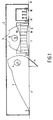
- the luminaire in Fig. 1 has a housing 1 with a light emission window 2 in a plane P and a concave, asymmetrical reflector 3 in the housing.
- Means 4 for accommodating a tubular electric lamp, a linear fluorescent lamp in the Figure, alongside the light emission window 2 are present in the housing.
- An auxiliary reflector 5 projects through the light emission window 2 to the exterior and is arranged opposite the means 4 for accommodating the lamp.
- the reflector 3 and the auxiliary reflector 5 already screen off the lamp to the extent that it is not visible from locations centrally below the luminaire.
- a second, concave, substantially symmetrical reflector 6 with a light window 7 substantially in plane P is present in the housing 1.
- the housing in addition has second means 8 for accommodating a tubular electric lamp, again a linear fluorescent lamp in the Figure, for the second reflector 6.
- the reflectors are made of aluminum with a semi-specular finish.
- the housing is painted and has a reflecting function for the lamp which is to be accommodated in the second means 8.
- the second reflector 6 is formed by two parts in the Figure. These parts are positioned so as to face one another, on either side of a lamp to be accommodated.
- slats 9 are present in the light window 7, extending in the second reflector and transversely thereto and situated in front of and behind the slat drawn in the Figure.
- the slats 9 have an interspacing of approximately 3 cm in the Figure. They are substantially V-shaped in cross-section with a concave, for example parabolic outer surface 9a. Parallel lines in the slats indicate this curvature.
- the slats 9 have substantially parallel surfaces 9b remote from the light window 7.
- the housing 1 has a recess 10 with an opening in the plane P defined by the light emission window 7, in which recess a power rail 11 is accommodated.
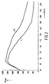
- Fig. 2 shows the illuminance on a wall as a function of the distance d to a ceiling in which a luminaire is accommodated.
- the Figure shows the illuminance (curve a ) obtained with a conventional luminaire having only the asymmetrical reflector of Fig. 1 and a 35 W fluorescent lamp of approximately 15 mm diameter.
- Curve a/s indicates the illuminance achieved with the luminaire according to the invention which contains two such fluorescent lamps.
- the lamp in the symmetrical reflector adds substantially no illuminance to the uppermost 30 cm of the wall. A substantial increase in the illuminance is not obtained until approximately one meter down from the ceiling, and the illuminance is more than doubled at a great distance from the ceiling. It can be derived from the curves that the lamp in the symmetrical reflector evenly illuminates also a vertical plane facing the wall and positioned at a comparatively low level.
Abstract
Description
Claims (3)
- A luminaire comprising:a housing (1) with a light emission window (2) in a plane P;a concave asymmetrical reflector (3) in the housing;means (4) in the housing for accommodating a tubular electric lamp alongside the light emission window (2); andan auxiliary reflector (5) which projects through the light emission window (2) to the exterior and which is positioned opposite the means (4) for accommodating the lamp, characterized in that a second, concave, substantially symmetrical reflector (6) with a light window (7) substantially in the plane P is present in the housing (1) next to the asymmetrical reflector (3), and in that second means (8) for accommodating a tubular electric lamp are present.
- A luminaire as claimed in Claim 1, characterized in that several parallel slats (9) extending transversely to the second reflector (6) are present in the light window (7).
- A luminaire as claimed in Claim 1 or 2, characterized in that the housing (1) comprises a recess (10) with an opening in the plane P, in which recess a power rail (11) is arranged.
Priority Applications (1)
| Application Number | Priority Date | Filing Date | Title |
|---|---|---|---|
| EP97202136A EP0833100B1 (en) | 1996-09-30 | 1997-07-11 | Luminaire |
Applications Claiming Priority (3)
| Application Number | Priority Date | Filing Date | Title |
|---|---|---|---|
| EP96202716 | 1996-09-30 | ||
| EP96202716 | 1996-09-30 | ||
| EP97202136A EP0833100B1 (en) | 1996-09-30 | 1997-07-11 | Luminaire |
Publications (3)
| Publication Number | Publication Date |
|---|---|
| EP0833100A2 true EP0833100A2 (en) | 1998-04-01 |
| EP0833100A3 EP0833100A3 (en) | 2000-01-26 |
| EP0833100B1 EP0833100B1 (en) | 2001-11-14 |
Family
ID=26143207
Family Applications (1)
| Application Number | Title | Priority Date | Filing Date |
|---|---|---|---|
| EP97202136A Expired - Lifetime EP0833100B1 (en) | 1996-09-30 | 1997-07-11 | Luminaire |
Country Status (1)
| Country | Link |
|---|---|
| EP (1) | EP0833100B1 (en) |
Cited By (1)
| Publication number | Priority date | Publication date | Assignee | Title |
|---|---|---|---|---|
| AU2004201558B2 (en) * | 2003-07-22 | 2006-03-02 | Acuity Brands, Inc. | Improved luminaires for illumination of outdoor panels |
Citations (1)
| Publication number | Priority date | Publication date | Assignee | Title |
|---|---|---|---|---|
| JPH087622A (en) | 1994-06-22 | 1996-01-12 | Matsushita Electric Works Ltd | Wall surface luminaire |
Family Cites Families (5)
| Publication number | Priority date | Publication date | Assignee | Title |
|---|---|---|---|---|
| US4349866A (en) * | 1980-05-27 | 1982-09-14 | General Signal Corporation | Light reflection system with asymmetric reflector assembly |
| GB8311075D0 (en) * | 1983-04-22 | 1983-05-25 | Hall S M | Light fitting for wall illumination |
| US4564888A (en) * | 1984-11-28 | 1986-01-14 | Linear Lighting Corp. | Wall-wash lighting fixture |
| US5146393A (en) * | 1991-03-06 | 1992-09-08 | Genlyte, Inc. | Fluorescent fixture with wall wash feature |
| DE9115705U1 (en) * | 1991-12-18 | 1992-02-13 | Dipl.-Ing. Schaer-Luederitz Gmbh, 4990 Luebbecke, De |
-
1997
- 1997-07-11 EP EP97202136A patent/EP0833100B1/en not_active Expired - Lifetime
Patent Citations (1)
| Publication number | Priority date | Publication date | Assignee | Title |
|---|---|---|---|---|
| JPH087622A (en) | 1994-06-22 | 1996-01-12 | Matsushita Electric Works Ltd | Wall surface luminaire |
Cited By (1)
| Publication number | Priority date | Publication date | Assignee | Title |
|---|---|---|---|---|
| AU2004201558B2 (en) * | 2003-07-22 | 2006-03-02 | Acuity Brands, Inc. | Improved luminaires for illumination of outdoor panels |
Also Published As
| Publication number | Publication date |
|---|---|
| EP0833100A3 (en) | 2000-01-26 |
| EP0833100B1 (en) | 2001-11-14 |
Similar Documents
| Publication | Publication Date | Title |
|---|---|---|
| US4229782A (en) | High efficiency lighting units with beam cut-off angle | |
| US4336576A (en) | Lighting apparatus | |
| US7488085B2 (en) | Compact task ambient luminaire with twin tube lamp | |
| US3591798A (en) | Lighting fixture | |
| US6280052B1 (en) | Light diffuser | |
| DK166102B (en) | LAMP WITH INDIRECT MIRROR | |
| US4698734A (en) | Lensed indirect luminaire with side angle brightness control | |
| PL316795A1 (en) | Lighting fitting | |
| US7156540B2 (en) | Lighting fixture including two reflectors | |
| CA2180712C (en) | Lighting fixture having a parabolic louver | |
| US4760505A (en) | Indirect lighting fixture | |
| US5865528A (en) | Indirect light fixture | |
| US5272607A (en) | Lighting fixture | |
| AU677410B2 (en) | Luminaire | |
| US4237528A (en) | Luminaire | |
| US4975812A (en) | Indirect lighting fixture | |
| US6733154B1 (en) | Indirect luminaire | |
| US6210018B1 (en) | Angled mounting bracket for high lumen output fluorescent lamp down light fixture | |
| EP0833100B1 (en) | Luminaire | |
| JP4465113B2 (en) | lighting equipment | |
| US8702268B1 (en) | 2×4 dawn light volumetric fixture | |
| US20050276043A1 (en) | Support for the fluorescent light | |
| KR910008650Y1 (en) | Fluorescent light | |
| EP1152187A2 (en) | Lighting device | |
| US3163365A (en) | Lanterns for street lighting |
Legal Events
| Date | Code | Title | Description |
|---|---|---|---|
| PUAI | Public reference made under article 153(3) epc to a published international application that has entered the european phase |
Free format text: ORIGINAL CODE: 0009012 |
|
| AK | Designated contracting states |
Kind code of ref document: A2 Designated state(s): AT BE DE ES FR GB IT NL |
|
| PUAL | Search report despatched |
Free format text: ORIGINAL CODE: 0009013 |
|
| AK | Designated contracting states |
Kind code of ref document: A3 Designated state(s): AT BE CH DE DK ES FI FR GB GR IE IT LI LU MC NL PT SE |
|
| 17P | Request for examination filed |
Effective date: 20000726 |
|
| AKX | Designation fees paid |
Free format text: AT BE DE ES FR GB IT NL |
|
| 17Q | First examination report despatched |
Effective date: 20000928 |
|
| GRAG | Despatch of communication of intention to grant |
Free format text: ORIGINAL CODE: EPIDOS AGRA |
|
| GRAG | Despatch of communication of intention to grant |
Free format text: ORIGINAL CODE: EPIDOS AGRA |
|
| GRAH | Despatch of communication of intention to grant a patent |
Free format text: ORIGINAL CODE: EPIDOS IGRA |
|
| GRAH | Despatch of communication of intention to grant a patent |
Free format text: ORIGINAL CODE: EPIDOS IGRA |
|
| GRAA | (expected) grant |
Free format text: ORIGINAL CODE: 0009210 |
|
| RIC1 | Information provided on ipc code assigned before grant |
Free format text: 7F 21S 8/00 A, 7F 21V 7/09 B |
|
| AK | Designated contracting states |
Kind code of ref document: B1 Designated state(s): AT BE DE ES FR GB IT NL |
|
| REF | Corresponds to: |
Ref document number: 208874 Country of ref document: AT Date of ref document: 20011115 Kind code of ref document: T |
|
| REF | Corresponds to: |
Ref document number: 69708243 Country of ref document: DE Date of ref document: 20011220 |
|
| REG | Reference to a national code |
Ref country code: GB Ref legal event code: IF02 |
|
| REG | Reference to a national code |
Ref country code: ES Ref legal event code: FG2A Ref document number: 2167674 Country of ref document: ES Kind code of ref document: T3 |
|
| PG25 | Lapsed in a contracting state [announced via postgrant information from national office to epo] |
Ref country code: ES Free format text: LAPSE BECAUSE OF NON-PAYMENT OF DUE FEES Effective date: 20020712 |
|
| PGFP | Annual fee paid to national office [announced via postgrant information from national office to epo] |
Ref country code: FR Payment date: 20020724 Year of fee payment: 6 |
|
| PGFP | Annual fee paid to national office [announced via postgrant information from national office to epo] |
Ref country code: AT Payment date: 20020725 Year of fee payment: 6 |
|
| PG25 | Lapsed in a contracting state [announced via postgrant information from national office to epo] |
Ref country code: BE Free format text: LAPSE BECAUSE OF NON-PAYMENT OF DUE FEES Effective date: 20020731 |
|
| PGFP | Annual fee paid to national office [announced via postgrant information from national office to epo] |
Ref country code: GB Payment date: 20020731 Year of fee payment: 6 |
|
| PGFP | Annual fee paid to national office [announced via postgrant information from national office to epo] |
Ref country code: DE Payment date: 20020918 Year of fee payment: 6 |
|
| PLBE | No opposition filed within time limit |
Free format text: ORIGINAL CODE: 0009261 |
|
| STAA | Information on the status of an ep patent application or granted ep patent |
Free format text: STATUS: NO OPPOSITION FILED WITHIN TIME LIMIT |
|
| 26N | No opposition filed | ||
| REG | Reference to a national code |
Ref country code: FR Ref legal event code: D6 |
|
| REG | Reference to a national code |
Ref country code: GB Ref legal event code: 746 Effective date: 20021209 |
|
| BERE | Be: lapsed |
Owner name: KONINKLIJKE *PHILIPS ELECTRONICS N.V. Effective date: 20020731 |
|
| PG25 | Lapsed in a contracting state [announced via postgrant information from national office to epo] |
Ref country code: NL Free format text: LAPSE BECAUSE OF NON-PAYMENT OF DUE FEES Effective date: 20030201 |
|
| NLV4 | Nl: lapsed or anulled due to non-payment of the annual fee |
Effective date: 20030201 |
|
| PG25 | Lapsed in a contracting state [announced via postgrant information from national office to epo] |
Ref country code: GB Free format text: LAPSE BECAUSE OF NON-PAYMENT OF DUE FEES Effective date: 20030711 Ref country code: AT Free format text: LAPSE BECAUSE OF NON-PAYMENT OF DUE FEES Effective date: 20030711 |
|
| PG25 | Lapsed in a contracting state [announced via postgrant information from national office to epo] |
Ref country code: DE Free format text: LAPSE BECAUSE OF NON-PAYMENT OF DUE FEES Effective date: 20040203 |
|
| GBPC | Gb: european patent ceased through non-payment of renewal fee |
Effective date: 20030711 |
|
| PG25 | Lapsed in a contracting state [announced via postgrant information from national office to epo] |
Ref country code: FR Free format text: LAPSE BECAUSE OF NON-PAYMENT OF DUE FEES Effective date: 20040331 |
|
| REG | Reference to a national code |
Ref country code: FR Ref legal event code: ST |
|
| REG | Reference to a national code |
Ref country code: ES Ref legal event code: FD2A Effective date: 20030811 |
|
| PG25 | Lapsed in a contracting state [announced via postgrant information from national office to epo] |
Ref country code: IT Free format text: LAPSE BECAUSE OF NON-PAYMENT OF DUE FEES;WARNING: LAPSES OF ITALIAN PATENTS WITH EFFECTIVE DATE BEFORE 2007 MAY HAVE OCCURRED AT ANY TIME BEFORE 2007. THE CORRECT EFFECTIVE DATE MAY BE DIFFERENT FROM THE ONE RECORDED. Effective date: 20050711 |