EP0833465B1 - Wireless communication system and method comprising a transreceiver and a plurality of remote wireless communication devices - Google Patents
Wireless communication system and method comprising a transreceiver and a plurality of remote wireless communication devices Download PDFInfo
- Publication number
- EP0833465B1 EP0833465B1 EP97305743A EP97305743A EP0833465B1 EP 0833465 B1 EP0833465 B1 EP 0833465B1 EP 97305743 A EP97305743 A EP 97305743A EP 97305743 A EP97305743 A EP 97305743A EP 0833465 B1 EP0833465 B1 EP 0833465B1
- Authority
- EP
- European Patent Office
- Prior art keywords
- transmitter
- wireless communication
- wireless
- devices
- transceiver
- Prior art date
- Legal status (The legal status is an assumption and is not a legal conclusion. Google has not performed a legal analysis and makes no representation as to the accuracy of the status listed.)
- Expired - Lifetime
Links
- 238000000034 method Methods 0.000 title claims description 4
- 230000005540 biological transmission Effects 0.000 description 8
- 230000001413 cellular effect Effects 0.000 description 2
- 238000010586 diagram Methods 0.000 description 2
- 238000001228 spectrum Methods 0.000 description 2
- 230000015556 catabolic process Effects 0.000 description 1
- 238000006731 degradation reaction Methods 0.000 description 1
- 238000001514 detection method Methods 0.000 description 1
- 230000009977 dual effect Effects 0.000 description 1
Images

Classifications
-
- H—ELECTRICITY
- H04—ELECTRIC COMMUNICATION TECHNIQUE
- H04B—TRANSMISSION
- H04B7/00—Radio transmission systems, i.e. using radiation field
- H04B7/24—Radio transmission systems, i.e. using radiation field for communication between two or more posts
- H04B7/26—Radio transmission systems, i.e. using radiation field for communication between two or more posts at least one of which is mobile
- H04B7/2603—Arrangements for wireless physical layer control
- H04B7/2606—Arrangements for base station coverage control, e.g. by using relays in tunnels
-
- H—ELECTRICITY
- H04—ELECTRIC COMMUNICATION TECHNIQUE
- H04W—WIRELESS COMMUNICATION NETWORKS
- H04W16/00—Network planning, e.g. coverage or traffic planning tools; Network deployment, e.g. resource partitioning or cells structures
- H04W16/24—Cell structures
- H04W16/26—Cell enhancers or enhancement, e.g. for tunnels, building shadow
Definitions
- This invention relates to wireless communication systems and methods. It has application in systems comprising a transceiver arranged to communicate with a plurality of remote wireless communication devices.
- ISM Industrial, Scientific and Medical
- US-A-5 701 590 discloses a radio communication system wherein on detection of a larger number of channels than those in use are receiving signals at the same time, it is determined that transmission intermodulation has occurred in a mobile station. A selected busy channel is then changed so that the frequency generated by transmission intermodulation is different than the reception frequency of an idle channel. Hence, idle channels are not blocked by the transmission intermodulation of the mobile station and degradation of use efficiency of frequencies can be prevented.
- US-A-4 780 885 relates to a real-time frequency management system which permits the automatic selection of optimum operational frequencies in HF communication transmitters and receivers.
- US-A-5 416 829 relates to a dual mode cellular radio communication apparatus having an echo canceller employed in both analog and digital modes.
- US-A-5 550 893 discloses a cellular telephone with uniform speech quality and perceived sound independently of whether the phone is being operated in digital or analog mode.
- US-A-4 479 215 relates to a power-line-carrier communications system capable of shifting operating frequency to avoid power-line interference.
- a wireless communications system comprising a plurality of wireless communication devices adapted to communicate with a transceiver, the transceiver including a transmitter, a plurality of receivers, a plurality of transmitter control circuits each of which is adapted to enable the transmitter to transmit to a selected one of the wireless communications devices when connected thereto and a switch circuit for connecting the transmitter control circuits to the transmitter one at a time so as to prevent interference between the communication devices, characterized in that the transceiver further comprises a host system adapted to control operation of the switch circuit, the host system being coupled to a corresponding one of the plurality of receivers and being adapted to operate the switch on receipt of a signal from the receiver to which it is coupled so as to connect the appropriate control circuit to the transmitter, which enables the transmitter to transmit to the communication device from which the signal was received.
- the plurality of host systems may also each be energizable on demand, for example from host systems which utilise the transmitter to communicate with the wireless communication devices.
- the plurality of host systems are all connected to a single switch control means which controls the switch circuit in accordance with control signals received from the host systems.
- the transceiver may be a multi-mode transceiver and the wireless communications devices at least in part utilise a common RF spectrum.
- a method of minimising interference among a plurality of wireless communication devices comprising the steps of providing a transceiver for communicating with the devices, the transceiver including a transmitter, a plurality of receivers, a plurality of transmitter control circuits, each of which is adapted to enable the transmitter to transmit to a selected one of the wireless communications devices when connected thereto and a switch circuit for connecting the transmitter control circuits to the transmitter; characterized by providing a host system coupled to the plurality of receivers; receiving a signal in a receiver from a communication device, causing the host system to operate the switch circuit to connect an appropriate transmitter control circuit to the transmitter; transmitting only to the communication device from which the receiver has received a signal.
- communication system 10 includes multi-mode transceiver 12, wireless communication devices 14a and 14b, and host systems 36a and 36b.
- Multi-mode transceiver 12 transmits and receives messages from wireless communication devices 14a and 14b, even through devices 14a and 14b may be operating at different frequencies, in different transmission modes, or in overlapping bandwidths.
- Multi-mode transceiver 12 includes transmitter portion 16, switch 18, control circuits 20a and 20b, and receiver circuits 22a and 22b.
- Transmitter portion 16 transmits messages to wireless communication devices 14a and 14b. Transmitter portion 16 produces an output signal whose frequency and signal characteristics are controlled by control circuits 20a or 20b.
- Switch 18 connects one of control circuits 20a or 20b to transmitter portion 16.
- An analog RF switch is suitable for use as switch 18.
- Control circuit 20a and 20b control the output signal frequency and signal characteristics of transmitter portion 16. Control circuits 20a and 20b receive information for transmission from host systems 36a and 36b.
- each transmitter has its own control circuit.
- the present invention separates control circuits 20a and 20b from transmitter portion 16 by switch 18.
- transmitter portion 16 can transmit to only one of devices 14a or 14b at a time. Interference between transmitters is eliminated because only one transmitter 12 is in use.
- Receiver circuits 22a and 22b receive incoming information signals from devices 14a and 14b and forward the information to host systems 36a and 36b. Operation of transceiver 12 assumes that device 14a initiates communication with host system 36a, and that host system 36b initiates communication with device 14b. However, the present invention may be modified to accommodate any combination of controlling schemes.
- Receiver circuits 22a and 22b include receivers 24a and 24b, amplifiers 26a and 26b, and decoders 28a and 28b.
- Receivers 24a and 24b receive signals from devices 14a and 14b.
- Amplifiers 26a and 26b amplify the signals received by receivers 24a and 24b.
- Decoders 28a and 28b decode the information from the amplified signals.
- Devices 14a and 14b include control circuits 30a and 30b, transmitters 32a and 32b, and receivers 34a and 34b.
- Devices 14a and 14b are preferably different types of wireless devices. They may include any combination of wireless data terminals, wireless hand-held scanners, wireless electronic shelf labels, and wireless voice products. There may be many such devices and their associated control circuits (e.g., 20a and 20b), receiver circuits (e.g., 22a and 22b), and host systems (e.g., 36a and 36b) in system 10, but only two are shown for clarity.
- control circuits e.g., 20a and 20b
- receiver circuits e.g., 22a and 22b
- host systems e.g., 36a and 36b
- host systems 36a and 36b provide information for transmission to devices 14a and 14b and receive information from devices 14a and 14b. Additionally, host systems 36a and 36b sample the output signals from decoders 28a and 28b to control operation of switch 18 to initiate transmission. Host systems 36a and 36b relinquish control over switch 18 when transmission of their information is finished.
- a single microprocessor 40 controls switch 18 instead of host systems 36a and 36b.
- switching may be controlled by host systems 36a and 36b or devices 14a and 14b.
- microprocessor 40 receives a signal from host systems 36a and 36b and changes switch 18 accordingly.
- wireless devices 14a and 14b initiate communication with host systems 36a and 36b
- microprocessor 40 receives a signal from receivers 22a and 22b and changes switch 18 accordingly.
Description
- This invention relates to wireless communication systems and methods. It has application in systems comprising a transceiver arranged to communicate with a plurality of remote wireless communication devices.
- In today's retail environment, there may be many different types of wireless devices, such as wireless data terminals, wireless hand-held scanners, wireless electronic shelf labels and wireless voice products. Unfortunately, some of these devices may utilize the same RF spectrum, resulting in interference. One of the bands most often used today is the Industrial, Scientific and Medical (ISM) band.
- Therefore, it would be desirable to provide a communication system that could eliminate interference between wireless devices.
- US-A-5 701 590 discloses a radio communication system wherein on detection of a larger number of channels than those in use are receiving signals at the same time, it is determined that transmission intermodulation has occurred in a mobile station. A selected busy channel is then changed so that the frequency generated by transmission intermodulation is different than the reception frequency of an idle channel. Hence, idle channels are not blocked by the transmission intermodulation of the mobile station and degradation of use efficiency of frequencies can be prevented. US-A-4 780 885 relates to a real-time frequency management system which permits the automatic selection of optimum operational frequencies in HF communication transmitters and receivers. US-A-5 416 829 relates to a dual mode cellular radio communication apparatus having an echo canceller employed in both analog and digital modes. US-A-5 550 893 discloses a cellular telephone with uniform speech quality and perceived sound independently of whether the phone is being operated in digital or analog mode. US-A-4 479 215 relates to a power-line-carrier communications system capable of shifting operating frequency to avoid power-line interference.
- According to the invention in one aspect thereof a wireless communications system comprising a plurality of wireless communication devices adapted to communicate with a transceiver, the transceiver including a transmitter, a plurality of receivers, a plurality of transmitter control circuits each of which is adapted to enable the transmitter to transmit to a selected one of the wireless communications devices when connected thereto and a switch circuit for connecting the transmitter control circuits to the transmitter one at a time so as to prevent interference between the communication devices, characterized in that the transceiver further comprises a host system adapted to control operation of the switch circuit, the host system being coupled to a corresponding one of the plurality of receivers and being adapted to operate the switch on receipt of a signal from the receiver to which it is coupled so as to connect the appropriate control circuit to the transmitter, which enables the transmitter to transmit to the communication device from which the signal was received.
- The plurality of host systems may also each be energizable on demand, for example from host systems which utilise the transmitter to communicate with the wireless communication devices.
- In one preferred embodiment of the invention, the plurality of host systems are all connected to a single switch control means which controls the switch circuit in accordance with control signals received from the host systems.
- In embodiments of the invention, the transceiver may be a multi-mode transceiver and the wireless communications devices at least in part utilise a common RF spectrum.
- According to the invention in another aspect thereof a method of minimising interference among a plurality of wireless communication devices comprising the steps of providing a transceiver for communicating with the devices, the transceiver including a transmitter, a plurality of receivers, a plurality of transmitter control circuits, each of which is adapted to enable the transmitter to transmit to a selected one of the wireless communications devices when connected thereto and a switch circuit for connecting the transmitter control circuits to the transmitter; characterized by providing a host system coupled to the plurality of receivers; receiving a signal in a receiver from a communication device, causing the host system to operate the switch circuit to connect an appropriate transmitter control circuit to the transmitter; transmitting only to the communication device from which the receiver has received a signal.
- Additional benefits and advantages of the present invention will become apparent to those skilled in the art to which this invention relates from the subsequent description of the preferred embodiments and the appended claims, taken in conjunction with the accompanying drawings, in which:
- Fig. 1 is a block diagram of a first embodiment of the communication system of the present invention; and
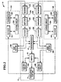
- Fig. 2 is a block diagram of a second embodiment of the communication system of the present invention.
-
- Referring now to the Drawings,
communication system 10 includesmulti-mode transceiver 12, wireless communication devices 14a and 14b, and host systems 36a and 36b. -
Multi-mode transceiver 12 transmits and receives messages from wireless communication devices 14a and 14b, even through devices 14a and 14b may be operating at different frequencies, in different transmission modes, or in overlapping bandwidths.Multi-mode transceiver 12 includestransmitter portion 16,switch 18, control circuits 20a and 20b, and receiver circuits 22a and 22b. -
Transmitter portion 16 transmits messages to wireless communication devices 14a and 14b.Transmitter portion 16 produces an output signal whose frequency and signal characteristics are controlled by control circuits 20a or 20b. -
Switch 18 connects one of control circuits 20a or 20b totransmitter portion 16. An analog RF switch is suitable for use asswitch 18. - Control circuit 20a and 20b control the output signal frequency and signal characteristics of
transmitter portion 16. Control circuits 20a and 20b receive information for transmission from host systems 36a and 36b. - In prior systems having a plurality of transmitters, each transmitter has its own control circuit. The present invention separates control circuits 20a and 20b from
transmitter portion 16 byswitch 18. Thus,transmitter portion 16 can transmit to only one of devices 14a or 14b at a time. Interference between transmitters is eliminated because only onetransmitter 12 is in use. - Receiver circuits 22a and 22b receive incoming information signals from devices 14a and 14b and forward the information to host systems 36a and 36b. Operation of
transceiver 12 assumes that device 14a initiates communication with host system 36a, and that host system 36b initiates communication with device 14b. However, the present invention may be modified to accommodate any combination of controlling schemes. - Receiver circuits 22a and 22b include receivers 24a and 24b, amplifiers 26a and 26b, and decoders 28a and 28b.
- Receivers 24a and 24b receive signals from devices 14a and 14b.
- Amplifiers 26a and 26b amplify the signals received by receivers 24a and 24b.
- Decoders 28a and 28b decode the information from the amplified signals.
- Devices 14a and 14b include control circuits 30a and 30b, transmitters 32a and 32b, and receivers 34a and 34b.
- Devices 14a and 14b are preferably different types of wireless devices. They may include any combination of wireless data terminals, wireless hand-held scanners, wireless electronic shelf labels, and wireless voice products. There may be many such devices and their associated control circuits (e.g., 20a and 20b), receiver circuits (e.g., 22a and 22b), and host systems (e.g., 36a and 36b) in
system 10, but only two are shown for clarity. - Using
transceiver 12, host systems 36a and 36b provide information for transmission to devices 14a and 14b and receive information from devices 14a and 14b. Additionally, host systems 36a and 36b sample the output signals from decoders 28a and 28b to control operation ofswitch 18 to initiate transmission. Host systems 36a and 36b relinquish control overswitch 18 when transmission of their information is finished. - With reference to Fig. 2, a
single microprocessor 40 controls switch 18 instead of host systems 36a and 36b. As in the first embodiment, switching may be controlled by host systems 36a and 36b or devices 14a and 14b. When host systems 36a and 36b initiate communication with devices 22a and 22b,microprocessor 40 receives a signal from host systems 36a and 36b and changes switch 18 accordingly. When wireless devices 14a and 14b initiate communication with host systems 36a and 36b,microprocessor 40 receives a signal from receivers 22a and 22b and changes switch 18 accordingly.
Claims (8)
- A wireless communications system comprising
a plurality of wireless communication devices (14A, 14B) adapted to communicate with a transceiver (12), the transceiver (12) including a transmitter (16), a plurality of receivers (22A, 22B), a plurality of transmitter control circuits (20A, 20B) each of which is adapted to enable the transmitter (16) to transmit to a selected one of the wireless communications devices (14A, 14B) when connected thereto and a switch circuit (18) for connecting the transmitter control circuits (20A, 20B) to the transmitter (16) one at a time so as to prevent interference between the communication devices, characterized in that the transceiver further comprises a host system (36A, 36B, 40) adapted to control operation of the switch circuit (18), the host system(36A, 368, 40) being coupled to a corresponding one of the plurality of receivers (22A, 22B) and being adapted to operate the switch (18) on receipt of a signal from the receiver (22A, 22B) to which it is coupled so as to connect the appropriate control circuit (22A, 22B) to the transmitter (16), which enables the transmitter (16) to transmit to the communication device (14A, 14B) from which the signal was received. - A wireless communication system according to claim 1, wherein the host system comprises a plurality of host systems (36A, 36B), each individually energizable on demand.
- A wireless communications system according to claim 2, wherein the plurality of host systems (36A, 36B) are all connected to a single switch control means (40) which controls the switch circuit (18) in accordance with control signals received from the host systems (36A, 36B).
- A wireless communication system according to any preceding claim, wherein the plurality of wireless communication devices (14A, 14B) have overlapping communication bandwidths.
- A wireless communication system wherein one of the communication devices (14A, 14B) comprises a wireless electronic shelf label.
- A wireless communication system wherein one of the communication devices (14A, 14B) comprises a wireless hand-held scanner.
- A wireless communication system wherein one of the communication devices (14A, 14B) comprises a wireless voice transceiver.
- A method of minimising interference among a plurality of wireless communication devices (14A, 14B) comprising the steps ofproviding a transceiver (12) for communicating with the devices (14A, 14B), the transceiver including a transmitter (16), a plurality of receivers (22A, 22B), a plurality of transmitter control circuits (20A, 20B), each of which is adapted to enable the transmitter (16) to transmit to a selected one of the wireless communications devices (14A, 14B) when connected thereto and a switch circuit (18) for connecting the transmitter control circuits (20A, 20B) to the transmitter (16); characterized byproviding a host system (36A, 36B, 40) coupled to the plurality of receivers (22A, 22B);receiving a signal in a receiver (22A, 22B) from a communication device (14A, 14B)causing the host system (36A, 36B, 40) to operate the switch circuit (18) to connect an appropriate transmitter control circuit (20A, 20B) to the transmitter (16);transmitting only to the communication device (14A, 14B) from which the receiver (22A, 22B) has received a signal.
Applications Claiming Priority (2)
| Application Number | Priority Date | Filing Date | Title |
|---|---|---|---|
| US08/721,603 US5930683A (en) | 1996-09-25 | 1996-09-25 | Communication system for preventing interference between wireless devices |
| US721603 | 1996-09-25 |
Publications (3)
| Publication Number | Publication Date |
|---|---|
| EP0833465A2 EP0833465A2 (en) | 1998-04-01 |
| EP0833465A3 EP0833465A3 (en) | 2001-07-18 |
| EP0833465B1 true EP0833465B1 (en) | 2004-02-25 |
Family
ID=24898585
Family Applications (1)
| Application Number | Title | Priority Date | Filing Date |
|---|---|---|---|
| EP97305743A Expired - Lifetime EP0833465B1 (en) | 1996-09-25 | 1997-07-30 | Wireless communication system and method comprising a transreceiver and a plurality of remote wireless communication devices |
Country Status (4)
| Country | Link |
|---|---|
| US (1) | US5930683A (en) |
| EP (1) | EP0833465B1 (en) |
| JP (1) | JP3895436B2 (en) |
| DE (1) | DE69727752T2 (en) |
Families Citing this family (6)
| Publication number | Priority date | Publication date | Assignee | Title |
|---|---|---|---|---|
| US6804304B1 (en) * | 1998-10-30 | 2004-10-12 | Broadcom Corporation | Reduction of aggregate EMI emissions of multiple transmitters |
| US6823483B1 (en) * | 1999-04-22 | 2004-11-23 | Broadcom Corporation | Physical coding sublayer for a multi-pair gigabit transceiver |
| US6674999B2 (en) * | 2001-03-16 | 2004-01-06 | Skyworks Solutions, Inc | Dynamically varying linearity system for an RF front-end of a communication device |
| US6841802B2 (en) * | 2002-06-26 | 2005-01-11 | Oriol, Inc. | Thin film light emitting diode |
| TWI414163B (en) * | 2009-12-04 | 2013-11-01 | Ind Tech Res Inst | Heterogeneous wireless sensor network bridge device and control method and flow balancing method for the same |
| FI125570B (en) | 2014-03-26 | 2015-11-30 | Mariella Labels Oy | An arrangement, system and method for reducing interference to radio frequencies in an electronic price tag system |
Family Cites Families (13)
| Publication number | Priority date | Publication date | Assignee | Title |
|---|---|---|---|---|
| US4002886A (en) * | 1975-06-20 | 1977-01-11 | Ronald Murl Sundelin | Electronic price display unit |
| US4500880A (en) * | 1981-07-06 | 1985-02-19 | Motorola, Inc. | Real time, computer-driven retail pricing display system |
| US4479215A (en) * | 1982-09-24 | 1984-10-23 | General Electric Company | Power-line carrier communications system with interference avoidance capability |
| IL67379A (en) * | 1982-12-01 | 1985-11-29 | Tadiran Israel Elect Ind Ltd | Real-time frequency management system for hf communication networks |
| US4578815A (en) * | 1983-12-07 | 1986-03-25 | Motorola, Inc. | Wide area coverage radio communication system and method |
| US4736453A (en) * | 1985-12-10 | 1988-04-05 | Schloemer Gerald R | Method and apparatus for making frequency channel assignment in a cellular or non-cellular radiotelephone communications system |
| SU1374435A1 (en) * | 1986-06-02 | 1988-02-15 | Войсковая Часть 25871 | Arrangement for switching communication channels |
| US4924363A (en) * | 1989-02-15 | 1990-05-08 | Dapopp Products Ltd. | Attention-attracting device for use beneath a display shelf |
| KR950007498B1 (en) * | 1990-11-30 | 1995-07-11 | 가부시끼가이샤 도시바 | Dual mode cellular radio communication apparatus having an echo canceller employed in both analog and digital modes |
| US5172314A (en) * | 1991-05-03 | 1992-12-15 | Electronic Retailing Systems International | Apparatus for communicating price changes including printer and display devices |
| US5448226A (en) * | 1994-02-24 | 1995-09-05 | Electronic Retailing Systems International, Inc. | Shelf talker management system |
| JP2692592B2 (en) * | 1994-07-08 | 1997-12-17 | 日本電気株式会社 | Multi-channel access radio equipment |
| US5550893A (en) * | 1995-01-31 | 1996-08-27 | Nokia Mobile Phones Limited | Speech compensation in dual-mode telephone |
-
1996
- 1996-09-25 US US08/721,603 patent/US5930683A/en not_active Expired - Lifetime
-
1997
- 1997-07-30 EP EP97305743A patent/EP0833465B1/en not_active Expired - Lifetime
- 1997-07-30 DE DE69727752T patent/DE69727752T2/en not_active Expired - Fee Related
- 1997-09-24 JP JP25806397A patent/JP3895436B2/en not_active Expired - Fee Related
Also Published As
| Publication number | Publication date |
|---|---|
| EP0833465A3 (en) | 2001-07-18 |
| JP3895436B2 (en) | 2007-03-22 |
| US5930683A (en) | 1999-07-27 |
| DE69727752T2 (en) | 2004-10-07 |
| EP0833465A2 (en) | 1998-04-01 |
| DE69727752D1 (en) | 2004-04-01 |
| JPH10262003A (en) | 1998-09-29 |
Similar Documents
| Publication | Publication Date | Title |
|---|---|---|
| AU695358B2 (en) | Cellular radio system, repeater and base station | |
| EP0664940B1 (en) | Rf repeaters for time division duplex cordless telephone system | |
| CN1106724C (en) | System and method for reducing cumulative noise in distributed antenna network | |
| EP0771082B1 (en) | Mobile station without a transmission/reception duplexer | |
| JP3308623B2 (en) | Diversity receiver | |
| US6360089B1 (en) | Radio apparatus with diversity antennas | |
| JPS6259425A (en) | Burst mode bidirectional radio communication system | |
| JPH06140959A (en) | Radio transmitter-receiver | |
| WO1998027748A3 (en) | Wireless communications station and system | |
| HUT73121A (en) | Mobile radio aerial installation | |
| JP3347099B2 (en) | Antenna switching circuit for mobile phone with built-in simple mobile phone | |
| EP0833465B1 (en) | Wireless communication system and method comprising a transreceiver and a plurality of remote wireless communication devices | |
| EP0715786B1 (en) | Base station equipment using diversity reception | |
| IE902089A1 (en) | "A relay base for a radiotelephone communication system" | |
| WO1998036510A1 (en) | Mobile satellite phone system incorporating symmetrical and non-symmetrical waveform modes | |
| US6549760B1 (en) | Communications device | |
| US6701157B2 (en) | Transmitter circuit architecture and method for reducing in-band noise in point to multipoint communication systems | |
| US6415136B1 (en) | Method of minimizing interference between devices which communicate in overlapping communication bands | |
| JP2000013281A (en) | Bidirectional filter for half-duplex type side-band transceiver and its operation method | |
| US20050143019A1 (en) | Mobile communication device | |
| KR100668106B1 (en) | Time matching device of base station system | |
| JP2008078928A (en) | Repeater equipment | |
| JP2001285222A (en) | Method for monitoring and controlling reception area, and broadcast system | |
| KR20030056130A (en) | Appratus for Selectively Providing the Transmitter Redundancy by using Transmitter Diversity Function | |
| JPH07162332A (en) | Hot stand-by transmitter-receiver |
Legal Events
| Date | Code | Title | Description |
|---|---|---|---|
| PUAI | Public reference made under article 153(3) epc to a published international application that has entered the european phase |
Free format text: ORIGINAL CODE: 0009012 |
|
| AK | Designated contracting states |
Kind code of ref document: A2 Designated state(s): DE FR GB |
|
| PUAL | Search report despatched |
Free format text: ORIGINAL CODE: 0009013 |
|
| AK | Designated contracting states |
Kind code of ref document: A3 Designated state(s): AT BE CH DE DK ES FI FR GB GR IE IT LI LU MC NL PT SE |
|
| 17P | Request for examination filed |
Effective date: 20020118 |
|
| AKX | Designation fees paid |
Free format text: DE FR GB |
|
| 17Q | First examination report despatched |
Effective date: 20020402 |
|
| GRAH | Despatch of communication of intention to grant a patent |
Free format text: ORIGINAL CODE: EPIDOS IGRA |
|
| GRAS | Grant fee paid |
Free format text: ORIGINAL CODE: EPIDOSNIGR3 |
|
| GRAA | (expected) grant |
Free format text: ORIGINAL CODE: 0009210 |
|
| AK | Designated contracting states |
Kind code of ref document: B1 Designated state(s): DE FR GB |
|
| REG | Reference to a national code |
Ref country code: GB Ref legal event code: FG4D |
|
| REF | Corresponds to: |
Ref document number: 69727752 Country of ref document: DE Date of ref document: 20040401 Kind code of ref document: P |
|
| ET | Fr: translation filed | ||
| PLBE | No opposition filed within time limit |
Free format text: ORIGINAL CODE: 0009261 |
|
| STAA | Information on the status of an ep patent application or granted ep patent |
Free format text: STATUS: NO OPPOSITION FILED WITHIN TIME LIMIT |
|
| 26N | No opposition filed |
Effective date: 20041126 |
|
| PGFP | Annual fee paid to national office [announced via postgrant information from national office to epo] |
Ref country code: FR Payment date: 20060725 Year of fee payment: 10 |
|
| PGFP | Annual fee paid to national office [announced via postgrant information from national office to epo] |
Ref country code: DE Payment date: 20060814 Year of fee payment: 10 |
|
| PGFP | Annual fee paid to national office [announced via postgrant information from national office to epo] |
Ref country code: GB Payment date: 20070730 Year of fee payment: 11 |
|
| PG25 | Lapsed in a contracting state [announced via postgrant information from national office to epo] |
Ref country code: DE Free format text: LAPSE BECAUSE OF NON-PAYMENT OF DUE FEES Effective date: 20080201 |
|
| REG | Reference to a national code |
Ref country code: FR Ref legal event code: ST Effective date: 20080331 |
|
| PG25 | Lapsed in a contracting state [announced via postgrant information from national office to epo] |
Ref country code: FR Free format text: LAPSE BECAUSE OF NON-PAYMENT OF DUE FEES Effective date: 20070731 |
|
| GBPC | Gb: european patent ceased through non-payment of renewal fee |
Effective date: 20080730 |
|
| PG25 | Lapsed in a contracting state [announced via postgrant information from national office to epo] |
Ref country code: GB Free format text: LAPSE BECAUSE OF NON-PAYMENT OF DUE FEES Effective date: 20080730 |