EP0841501A2 - Compound transmission - Google Patents
Compound transmission Download PDFInfo
- Publication number
- EP0841501A2 EP0841501A2 EP98101148A EP98101148A EP0841501A2 EP 0841501 A2 EP0841501 A2 EP 0841501A2 EP 98101148 A EP98101148 A EP 98101148A EP 98101148 A EP98101148 A EP 98101148A EP 0841501 A2 EP0841501 A2 EP 0841501A2
- Authority
- EP
- European Patent Office
- Prior art keywords
- transmission
- section
- mainshaft
- gear
- countershaft
- Prior art date
- Legal status (The legal status is an assumption and is not a legal conclusion. Google has not performed a legal analysis and makes no representation as to the accuracy of the status listed.)
- Granted
Links
Images


Classifications
-
- F—MECHANICAL ENGINEERING; LIGHTING; HEATING; WEAPONS; BLASTING
- F16—ENGINEERING ELEMENTS AND UNITS; GENERAL MEASURES FOR PRODUCING AND MAINTAINING EFFECTIVE FUNCTIONING OF MACHINES OR INSTALLATIONS; THERMAL INSULATION IN GENERAL
- F16H—GEARING
- F16H3/00—Toothed gearings for conveying rotary motion with variable gear ratio or for reversing rotary motion
- F16H3/02—Toothed gearings for conveying rotary motion with variable gear ratio or for reversing rotary motion without gears having orbital motion
- F16H3/08—Toothed gearings for conveying rotary motion with variable gear ratio or for reversing rotary motion without gears having orbital motion exclusively or essentially with continuously meshing gears, that can be disengaged from their shafts
- F16H3/087—Toothed gearings for conveying rotary motion with variable gear ratio or for reversing rotary motion without gears having orbital motion exclusively or essentially with continuously meshing gears, that can be disengaged from their shafts characterised by the disposition of the gears
- F16H3/093—Toothed gearings for conveying rotary motion with variable gear ratio or for reversing rotary motion without gears having orbital motion exclusively or essentially with continuously meshing gears, that can be disengaged from their shafts characterised by the disposition of the gears with two or more countershafts
- F16H3/095—Toothed gearings for conveying rotary motion with variable gear ratio or for reversing rotary motion without gears having orbital motion exclusively or essentially with continuously meshing gears, that can be disengaged from their shafts characterised by the disposition of the gears with two or more countershafts with means for ensuring an even distribution of torque between the countershafts
-
- F—MECHANICAL ENGINEERING; LIGHTING; HEATING; WEAPONS; BLASTING
- F16—ENGINEERING ELEMENTS AND UNITS; GENERAL MEASURES FOR PRODUCING AND MAINTAINING EFFECTIVE FUNCTIONING OF MACHINES OR INSTALLATIONS; THERMAL INSULATION IN GENERAL
- F16H—GEARING
- F16H57/00—General details of gearing
- F16H57/02—Gearboxes; Mounting gearing therein
- F16H57/021—Shaft support structures, e.g. partition walls, bearing eyes, casing walls or covers with bearings
-
- F—MECHANICAL ENGINEERING; LIGHTING; HEATING; WEAPONS; BLASTING
- F16—ENGINEERING ELEMENTS AND UNITS; GENERAL MEASURES FOR PRODUCING AND MAINTAINING EFFECTIVE FUNCTIONING OF MACHINES OR INSTALLATIONS; THERMAL INSULATION IN GENERAL
- F16H—GEARING
- F16H61/00—Control functions within control units of change-speed- or reversing-gearings for conveying rotary motion ; Control of exclusively fluid gearing, friction gearing, gearings with endless flexible members or other particular types of gearing
- F16H61/70—Control functions within control units of change-speed- or reversing-gearings for conveying rotary motion ; Control of exclusively fluid gearing, friction gearing, gearings with endless flexible members or other particular types of gearing specially adapted for change-speed gearing in group arrangement, i.e. with separate change-speed gear trains arranged in series, e.g. range or overdrive-type gearing arrangements
-
- Y—GENERAL TAGGING OF NEW TECHNOLOGICAL DEVELOPMENTS; GENERAL TAGGING OF CROSS-SECTIONAL TECHNOLOGIES SPANNING OVER SEVERAL SECTIONS OF THE IPC; TECHNICAL SUBJECTS COVERED BY FORMER USPC CROSS-REFERENCE ART COLLECTIONS [XRACs] AND DIGESTS
- Y10—TECHNICAL SUBJECTS COVERED BY FORMER USPC
- Y10T—TECHNICAL SUBJECTS COVERED BY FORMER US CLASSIFICATION
- Y10T74/00—Machine element or mechanism
- Y10T74/19—Gearing
- Y10T74/19219—Interchangeably locked
- Y10T74/19233—Plurality of counter shafts
Definitions
- the present invention relates to an improved compound mechanical chance gear transmission structure, preferably for compound transmissions of the multiple substantially identical countershaft type.
- the present invention relates to an improved compound mechanical transmission structure allowing, for a given transmission capacity and life, the provision of a lighter, axially shorter and/or less costly transmission as compared to comparable prior art transmission structures.
- Compound change gear transmissions usually vehicular transmissions for heavy duty vehicles, of the type having one or more auxiliary sections connected in series with a main transmission section are well known in the prior art. Briefly, by utilizing main and auxiliary transmission sections connected in series, assuming proper sizing of the ratio steps, the total of available transmission ratios is equal to the product of the main and auxiliary section ratios.
- Auxiliary transmission sections are of three general types: range type, splitter type or combined range/splitter type.
- the auxiliary section ratio step or steps are greater than the total ratio coverage of the main transmission section ratios used in both ranges and the main section is shifted progressively through its ratios in each range.
- Examples of compound transmissions having, range type auxiliary sections may be seen by reference to U.S. Pat. Nos. 3,105,395; 2,637,222 and 2,637,221.
- the ratio steps of the splitter auxiliary section are less than the ratio steps of the main transmission section and each main section ratio is split, or subdivided, by the Splitter section.
- Examples of compound change gear transmissions having a splitter type auxiliary sections may be seen by reference to U.S. Pat. Nos. 4,290,515; 3,799,002; 4,440,037 and 4,527,447.
- both range and splitter type ratios are provided allowing the main section to be progressively shifted through its ratios in at least two ranges and also allowing one or more of the main section ratios to be split in at least one range.
- main and auxiliary sections are relative and that if the designations of the main and auxiliary sections are reversed, the type of auxiliary section (either range or splitter) will also be reversed.
- the normally designated auxiliary is considered the main section, the normally designated main section would be considered a four-speed splitter type auxiliary section therefor.
- the main transmission section of a compound transmission is that section which contains the largest (or at least no less) number of forwards speed ratios, which allows selection of a neutral position, which contains the reverse ratio(s)and/or which is shifted (in manual or semiautomatic transmissions) by manipulation of a shift bar or shift rail or shift shaft/shift finger assembly as opposed to master/slave valve/cylinder arrangements or the like.
- the prior art compound change gear transmissions especially the prior art compound transmissions of the type having both range and splitter type auxiliary section gearing, such as the "Roadranger” type and “Super 10" type offered by Eaton Corporation and the “Ecosplit” type offered by Zahnradfabrik Friedrichshafen Aktiengesellschaft, are well received and widely used in manually shifted heavy duty vehicles.
- these and other types of prior art compound change gear transmissions are not totally satisfactory as it is an ongoing objective, especially@, for vehicular transmissions, to provide transmissions of equal or improved capacities and reliability which use fewer parts and/or are axially shorter and/or lighter in weight as compared to prior art transmissions of comparable capacity and reliability.
- compound transmissions of an improved structure which use fewer parts and/or are axially shorter and/or of a lighter weight as compared to comparable prior art compound transmissions of equivalent capacity and reliability.
- the main and auxiliary section countershafts form a coaxial assembly of countershafts supported solely by bearings in the front and rear end walls of the transmission housing, preferably one of the main and auxiliary section countershafts extend from the forward to the rearward housing end walls and the other of the countershafts is a generally tubular member surrounding and rotationally supported on the one countershaft and/or (ii) the mainshaft is supported solely by the input and/or output shafts without intermediate bearings journalled in an intermediate housing wall, for example, the inner ends of the input shaft assembly and the output shaft assembly may axially overlap and provide mutual support and the mainshaft may be a tubular member surrounding, preferably in a radially floating manner, the input and/or output shafts for independent rotation relative thereto.
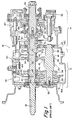
- FIGS. 1 and 1A are cross-sectional views of a prior art compound transmission.
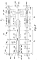
- FIG. 2 is a schematic illustration of a compound transmission, comparable to the transmission of FIGS. 1 and lA, according to the present invention.
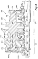
- FIG. 3 is a sectional view of a preferred embodiment of the transmission of FIG. 2.
- FIG. 4 is a sectional view of an alternate embodiment of the transmission of FIG. 2.
- FIG. 5 is a sectional view of another alternate embodiment of the transmission of FIG. 2.
- FIG. 5A is a partial view illustrating a structural modification of the transmission of FIG. 5.
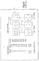
- FIG. 6 illustrates a typical shift pattern and typical gear ratios for the transmission of FIGS. 1 or 2.
- FIG. 7 illustrates a further alternate embodiment of the present invention.
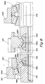
- FIG. 8 is a partial sectional view of an alternate embodiment of the present invention.
- compound transmission is used to designate a change speed or change gear transmission having a main transmission section and an auxiliary drive train unit, such as an auxiliary transmission section, connected in series whereby the selected gear reduction in the main transmission section may be compounded by further selected gear reduction in the auxiliary transmission section.
- upshift shall mean the shifting from a lower speed gear ratio to a higher speed gear ratio
- downshift shall mean the shifting from a higher speed gear ratio to a lower speed gear ratio.
- low speed gear or “low gear” as used herein shall designate a gear utilized for relatively lower forward speed operation in a transmission, i.e., a set of gears having a higher ratio of reduction of output shaft speed relative to the speed of the input shaft.
- Synchronized clutch assembly shall designate a clutch assembly” and words of similar import shall designate a clutch assembly utilized to nonrotatably couple a selected gear to a shaft by means of a positive clutch in which attempted engagement of said clutch is prevented until the members of the clutch are at substantially synchronous rotation and relative large capacity friction means are associated with the clutch members and are sufficient, upon initiation of a clutch engagement, to cause the clutch members and all members rotating therewith to rotate at a substantially synchronous speed.
- Transmission 10 comprises a main transmission section 12 connected in series with an auxiliary transmission section 14 having both range and splitter type gearing.
- transmission 10 is housed within a single multi-piece housing 16 and includes an input shaft 18 driven by a prime mover such as a diesel engine (not shown) through a selectively disengaged, normally engaged, friction master clutch (not shown).
- a prime mover such as a diesel engine (not shown) through a selectively disengaged, normally engaged, friction master clutch (not shown).
- the input shaft 18 carries an input gear for driving at least one countershaft assembly 22.
- input gear 20 simultaneously drives a plurality of substantially identical mainsection countershaft assemblies at substantially identical rotational speeds.
- Each of the mainsection countershaft assemblies comprises a mainsection countershaft 24 supported by bearings 26 and 28 in housing 16 and is provided with mainsection countershaft gears 30, 32, 34, 36 and 38 fixed thereto.
- a plurality of mainsection drive or mainshaft gears 40, 42 and 44 surround the transmission mainshaft 46 and are selectively clutchable, one at a time, to the mainshaft 46 for rotation therewith by sliding clutch collars 48 and 50 as is well known in the art.
- Clutch collar 48 may also be utilized to clutch input gear 20 to the mainshaft 46 to provide a direct drive relationship between the input shaft 18 and the mainshaft 46.
- each of the mainsection mainshaft gears encircles the mainshaft 46 and is in continuous meshing engagement with and is floatingly supported by the associated countershaft gear groups, which mounting means and special advantages resulting therefrom are explained in greater detail in above-mentioned United States Patent Nos. 3,105,395 and 3,335,616.
- clutch collars 48 and 50 are axially positioned by means of shift forks or yokes 52 and 54, respectively, associated with a shift bar housing assembly 56.
- Clutch collars 48 and 50 are, in the illustrated preferred embodiment, of the well known non-synchronized double acting jaw clutch type but may also be of the synchronized type as illustrated in U.S. Patent Nos. 4,989,706 and 5,141,087, the disclosures of which are incorporated herein by reference.
- Main section mainshaft gear 44 is the reverse gear and is in continuous meshing engagement with countershaft gears 38 by means of conventional intermediate idler gears 57 (see Fig 1A).
- Main section countershaft gear 32 is provided for powering power takeoff devices and the like.
- Jaw clutches 48 and 50 are three-position clutches in that they may be positioned in a centered axially nondisplaced, nonengaged position as illustrated or in a fully rightwardly engaged or fully leftwardly engaged position.
- Auxiliary transmission section 14 is connected in series with main transmission section 12 and is of the three-layer, four speed combined splitter/range type as illustrated in above-mentioned United States Patent No. 4,754,665.
- Mainshaft 46 extends into the auxiliary, section 14 and is journalled in the inward end of the output shaft 58 which extends from the rearward end of the transmission.
- Auxiliary transmission section 14 includes a plurality of substantially identical auxiliary countershaft assemblies 60 (see FIG. 1A) each comprising an auxiliary countershaft 62 supported by bearings 64 and 66 in housing 16 and carrying three auxiliary section countershaft gears 68, 70 and 72 fixed for rotation therewith.
- Auxiliary countershaft gears 68 are constantly meshed with and support auxiliary section splitter gear 74.
- Auxiliary countershaft gears 70 are constantly meshed with and support auxiliary section splitter/range gear 76 which surrounds the output shaft 58 at the end thereof adjacent the coaxial inner end of mainshaft 46.
- Auxiliary section countershaft gears 72 constantly mesh with and support auxiliary section range gear 78 which surrounds the output shaft 58.
- auxiliary section countershaft gears 68 and splitter gear 74 define a first gear layer
- auxiliary section countershaft gears 70 and splitter/range gear 76 define a second gear layer
- auxiliary section countershaft gears 72 and range gear 78 define a third layer, or gear group, of the combined splitter and range type auxiliary transmission section 14.
- a sliding two-position jaw clutch collar 80 is utilized to selectively couple either the splitter gear 74 or the splitter/range gear 76 to the mainshaft 46 while a two-position synchronized clutch assembly 82 utilized to selectively couple the splitter/range gear 76 or the range gear 78 to the output shaft 58.
- the structure and function of double-acting jaw clutch collar 80 is substantially identical to the structure and function of the sliding clutch collars 48 and 50 utilized in the main transmission section 12 and the function of double-acting synchronized clutch assembly 82 is substantially identical to the structure and function of prior art double-acting synchronized clutch assembly, examples of which may be seen by reference to United States Patent Nos.
- the splitter jaw clutch 80 is a two-position clutch assembly which may be selectively positioned in the rightwardmost or leftwardmost positions for engaging either gear 76 or gear 74, respectively, to the mainshaft 46.
- Splitter jaw clutch 80 is axially positioned by means of a shift fork 84 controlled by a two-position piston actuator 86 which is operable by a driver selection switch such as a button or the like on the shift knob (not shown) as is known in the prior art.
- Two-position synchronized clutch assembly 82 is also a two-position clutch which may be selectively positioned in either the rightwardmost or leftwardmost positions thereof for selectively clutching either gear 78 or 76, respectively, to output shaft 58.
- Clutch assembly 82 is positioned by means of a shift fork 88 operated by means of a two-position piston device 90.
- auxiliary transmission section 14 is a three layer auxiliary section of the combined range and splitter type providing four selectable speeds or drive ratios between the input (mainshaft 46) and output (output shaft 58) thereof.
- the mainsection 12 provides a reverse and three potentially selectable forward speeds.
- one of the selectable mainsection forward gear ratios, the low speed gear ratios associated with mainshaft gear 42, is not utilized in the high range.
- transmission 10 is properly designated as a " (2 + 1) X (2X2) " type transmission providing nine or ten selectable forward speeds, depending upon the desirability and practicality of splitting the low gear ratio.
- the shift pattern for shifting transmission 10 is schematically illustrated in FIG. 6. Divisions in the vertical direction at each gear lever position signify splitter shifts while movement in the horizontal direction from the three/four and five/six leg of the H pattern to the seven/eight and nine/ten leg of the H pattern signifies a shift from the low range to the high range of the transmission.
- splitter shifting is accomplished in the usual manner by means of a vehicle operator actuated splitter button or the like, usually a button located at the shift lever knob while operation of the range clutch shifting assembly is an automatic response to movement of the gear shift lever between the central and rightwardmost legs of the shift pattern as illustrated in FIG. 2 and will be described in greater detail below.
- Range shift devices of this general type are known in the prior art and may be seen by reference to above-mentioned United States Patent Nos. 3,429,202; 4,455,883; 4,561,325 and 4,663,725.
- the mainsection ratio steps should be generally equal
- the splitter step should be generally equal to the square root of the mainsection ratio steps
- the splitter steps are about 33.307o while the range step is about 316'7o which is generally suitable for a " 2 + 1 " main transmission section having about 7817o steps as the square root of 1.78 equals about 1.33 and 1.78 raised to the second power (i.e. N equals 2) equals about 3.16.
- Housing 16 which may be a multiple piece assembly as illustrated, includes a front end wall 16A, a rear end wall 16B and an intermediate wall 16C. It is noted that bearing 28 supporting the rearward end of mainsection countershaft 24, bearing 64 supporting the forward end of auxiliary countershaft 62 and bearing 74A supporting gear 74 and indirectly mainshaft 46 are all supported in the intermediate wall 16C of housing 16.
- countershaft gears are shown as fixed to the countershafts while certain of the mainshaft and/or output shaft gears are shown as selectively clutchable to the shafts associated therewith. While this is the preferred construction, the present invention is equally applicable to a functionally equivalent structure wherein certain of the mainshaft and/or output shaft gears are fixed to their associated shafts and the countershaft gears are selectively clutchable to the countershafts.
- FIGS. 2, 3, 4 and 5, 10-speed transmissions 110, 210 and 310, respectively, are illustrated.
- Transmissions 110, 210 and 310 all utilize the structure of the present invention.
- the functions and operations, but not the structures, of the parts of transmissions 110, 210 and 310 are identical to the function and operation of the parts of transmission 10 illustrated in FIGS. 1 and 1A.
- Parts of transmissions 110, 210 and 310 corresponding functionally and operationally to parts of transmission 10 will be assigned like reference numerals with a 1, 2 or 3, respectively, prefixed thereto.
- transmission 110 of the present invention is illustrated. While different in structure, the function and operation of transmission 110 is substantially identical to that of transmission 10 described above. As with transmission 10, transmission 110 includes a mainsection 112 and an auxiliary section 114, both contained within housing 116. Housing 116 includes a forward end wall 116A and a rearward end wall 116B, but not an intermediate wall corresponding to intermediate wall 16C of transmission 10.
- Input shaft 118 carries input gear 120 fixed for rotation therewith and defines a rearwardly opening pocket 118A wherein a reduced diameter extension 158A of output shaft 158 is piloted.
- a non-friction bushing 118B or the like may be provided in pocket or blind bore 118A.
- the forward end of input shaft 118 is supported by bearing 118C in front end wall 116A while the rearward end 158C of output shaft 158 is supported by bearing assembly 158D in rear and wall 116B.
- Bearing assembly 158D may be a pair of opposed taper bearings or a single roller or ball bearing as is illustrated in FIG. 3.
- the mainshaft 146 which carries mainshaft clutches 148 and 150, and the mainshaft splitter clutch 180 is in the form of a generally tubular body 146A having an externally splined outer surface 146B and an axially extending through bore 146C for passage of output shaft 158. Shift forks 152 and 154 are provided for shifting clutches 148 and 150, respectively.
- Mainshaft 146 is independently rotatable relative to input shaft 118 and output shaft 158 and preferably is free for limited radial movements relative thereto.
- the mainsection 112 includes two substantially identical mainsection countershaft assemblies 122 each comprising a mainsection countershaft 124 carrying countershaft gears 130, 132, 134, 136 and 138 fixed thereto. Gear pairs 130, 134, 136 and 138 are constantly meshed with input gear 118, mainshaft gears 140 and 142 and idler 157 which is meshed with reverse mainshaft gear 144, respectively.
- Mainsection countershaft 124 extends rearwardly into the auxiliary section where its rearward end 124A is supported directly or indirectly in rear housing end wall 116B.
- the auxiliary section 114 includes two substantially identical auxiliary countershaft assemblies 160 each including an auxiliary countershaft 162 carrying auxiliary countershaft gears 168, 170 and 172 for rotation therewith.
- Auxiliary countershaft gear pairs 168, 170 and 172 are constantly meshed with splitter gear 174, splitter/range gear 176 and range gear 178, respectively.
- Splitter clutch 180 is fixed to mainshaft 146 for selectively clutching either gear 174 or 176 thereto while synchronized range clutch 182 is fixed to output shaft 158 for selectively clutching either gear 176 or gear 178 thereto.
- Auxiliary countershafts 162 are generally tubular in shape definig a through bore 162A for receipt of the rearward extensions of the mainsection countershafts 124.
- Bearings or bushings 162B and 162C are provided to rotatably support auxiliary countershaft 162 on mainsection countershaft 124.
- Bearing 162D directly or indirectly supports the rear ends of countershafts 124 and 162 in the rear end wall 116B.
- Transmission 110 is functionally and operationally identical to prior art transmission 10 described above.
- Transmission 110 differs structurally from transmission 10 in that the mainshaft 146 is supported solely by the input and/or output shaft, one of the countershafts, mainsection countershafts 124, extends from the front end wall 116A to the rear end wall 116B and the other countershafts, auxiliary countershafts 162, are tubular members telescopically surrounding the one of the countershafts.
- This improved structure allows elimination of the intermediate wall 16C and bearings 28, 64 and 74A required for transmission 10.
- Compared to transmission 10, for similar capacity and reliability" transmission 110 is considerably shorter and lighter.
- transmission 10 will have a length of about 65 cm (25.8 inches) and a weight of about 288 kg (634 lbs.) compared to an estimated length of about 47,5 cm (18.7 inches) and weight of about 207 kg (455 lbs.) for spur gear transmission 110 of the present invention and about 52 cm (20.5 inches) and 211 kg (465 lbs.) for helically geared transmission 310 of the present invention to be described below.
- the input shaft 118 could extend further rearwardly to adjacent the rear end wall 116B or the input and output shafts could have inner ends meeting for mutual support at a point intermediate the end walls of the transmission.
- one or more of the ja@, clutches 148, 150 and/or 180 could be blocked and/or synchronized. While the structure of the present invention is especially advantageous for multiple substantially identical countershaft type transmissions, it is also applicable to single countershaft and swap shaft type transmissions.
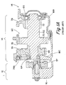
- FIG. 4 illustrates a portion of transmission 210, an alternate embodiment of the present invention.
- Transmission 210 differs from transmission 110 in that the auxiliary countershaft 262 extends from the rear end wall 216B to the front end wall 216A and is rotatably supported therein by bearings 262B and 26SA, respectively.
- the mainsection countershaft assembly 222 comprises a generally tubular mainsection countershaft 224 carrying mainsection countershaft gears 230, 234, 236 and 238 fixed for rotation therewith. Needle bearings 224A and 224B support shaft 224 for rotation on the forward extension of auxiliary countershaft 262.
- transmission 210 is substantially identical to that of transmission 110.
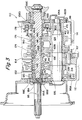
- Transmission 310 an alternate embodiment of the present invention, is illustrated in FIG. 5.
- Transmission 310 has been designed primarily for helical gearing while the transmissions 10, 110 and 210 are intended primarily for spur gearing.
- transmission 310 is a " (2 + 1)x(2x2) " type compound transmission comprising a main section 312 and an auxiliary section 314 connected in series therewith, both within a common housing 316 having a forward 316A and a rearward 316B end wall but not an intermediate wall corresponding to intermediate wall 16C of prior art transmission 10.
- Input shaft 318 carries input gear 320 fixed for rotation therewith and defines an inwardly extending reduced diameter portion 318A which directly or indirectly supports the front end 346A of mainshaft 346.
- Output shaft 358 extends from the rear end of transmission 310 and carries splines 358A for receipt of an output flange 358B.
- the inner end 358C of output shaft 358 is provided with an inwardly and rearwardly tapered surface 358D for direct or indirect support of the rear end 346B of mainshaft 346.
- Input shaft 318 is supported in front end wall 316A by taper roller bearing 318B while output shaft 358 is supported in rear end wall 316B by dual taper roller bearing assembly 358E.
- the mainshaft 346 carries mainshaft clutches 348 and 350 and the splitter clutch 380, and extends generally coaxially between and is supported by the inner ends of the input and output shafts.
- Mainshaft gears 340, 342 and 344, splitter gear 374 and splitter/range gear 376 surround the mainshaft, preferably for limited radial movement relative thereto, and are selectively clutchable thereto by clutches 348, 350 and 380.
- Range clutch 382 is carried by output shaft 358 which is surrounded by splitter/range gear 376 and range gear 378. Clutch 382 is effective to clutch either gear 376 or gear 378 to the output shaft 358.
- the function and operation of transmission 310 is the same as that of transmission 10, 110 and 210 discussed above.
- the countershaft assemblies 322 and 360 are substantially identical to the mainsection and auxiliary countershaft assemblies 122 and 160 of transmission 110 described below.
- mainsection countershaft(s) 324 carries countershaft gears 330, 334, 336 and 338 fixed thereto which are constantly meshed with and/or support, gears 318, 340, 342 and idler gear 357 while auxiliary countershaft(s) 362 carries auxiliary countershaft gears 368, 370,372 which are constantly meshed with gears 374, 376 and 378.
- the auxiliary countershaft is generally tubular and telescopically surrounds the rear end 324A of the mainsection countershaft and is directly or indirectly rotatably supported by bearings 362A, 362B and 362C thereon.
- a bearing 326 supports the forward end of countershaft 324 in front wall 316A while a bearing 362C supports, directly or indirectly, the rearward end of countershaft 324 in the rear end wall 316B.
- the reduced diameter extension 318A of the input shaft 318 carries an axial roller bearing 318C and a generally spherical washer 318D of bearing steel which will abut a generally complimentary radially inwardly and axially rearwardly tapered surface 346C provided on the front end 346A of the mainshaft 346.
- the hub portion 376A of range/splitter gear 376 surrounds the reduced diameter rearward portion 346B of the mainshaft 346 which also carries two spherical washers 346D and 346E, structurally identical to washer 318D, which interact with generally complimentary inclined surfaces 346F on the mainshaft and 358D on the output shaft, respectively.
- Axial roller bearings 346G and 346H separate the spherical washers from the hub portion 376A.
- Axial bearings are bearings designed to transmit an axial load between two relatively rotatable members.
- a typical axial bearing will include rollers having an axis rotation extending radially relative to the axis of rotation 318E/358F of the relatively rotating parts.
- the mainshaft 346 is thus supported directly or indirectly at its front end by input shaft 318 while the spherical washer 318D and surface 346C allow for a limited amount of radial movement of the mainshaft relative to the axis of rotation 318E of the input shaft.
- the mainshaft is supported directly or indirectly at its rear end by the output shaft 358 while spherical washers 346D and 346E interact with tapered surfaces 346F and 358D to allow a limited amount of radial movement of the mainshaft relative to the axis of rotation 358F of the output shaft 358 which is substantially coaxial with axis 318E.
- gearing of transmission 310 is helical which results in the creation of axial forces on the various transmission components. Forward axial forces on the mainshaft 346 and/or on the splitter/range gear 376 will be transferred to the housing through bearings 346G, 318C and/or 318B while rearward axial forces on the mainshaft and splitter/range gear will be transferred to the housing through bearings 346G, 346H and/or 358E.
- the mainshaft 346 is supported solely, by the input and output shafts, preferably with a limited degree of radial freedom or float, requiring no intermediate support to the housing and allowing the transfer of axial forces associated with helical gearing to the housing through appropriate bearings.
- FIG. 5A illustrates a structural modification to transmission 310.
- the spherical washers 346DD and 346EE replace the washers 346D and 346E illustrated in FIG. 5.
- Washers 346DD and 346EE include axially extending hubs 346DDA and 346EEA which provide a pilot surface for bearings 346G and 346H respectively to maintain the bearing cages and rollers parallel to surfaces 346DDB and 346EEB respectively.
- transmission 402 is schematically illustrated in FIG. 7. Unlike transmissions 10, 110, 210 and 310 described above, transmission 402 is a "(2)x(4)x(2)" type 16-speed transmission having a two-speed splitter section 404, a four forward-speed mainsection 406 and a two-speed range section 408, all connected in series.
- an input shaft 410 is supported in the transmission housing forward wall (not shown) by bearing 411 and is surrounded by two input gears 412 and 414, a selected one of which is clutched to the input shaft by synchronized clutch 416 to provide a two-speed splitter input section.
- Front countershaft assemblies 418 each include a countershaft 420 camming countershaft gears 422, 424, 426, 428, 430 and 432. Gears 422 and 424 are constantly meshed with the input gears 412 and 414.
- gears 426, 428, 430 and 432 are constantly meshed with mainshaft gears 434, 436, 438 and a reverse idler (not shown) meshed with reverse mainshaft gear 440.
- Double acting synchronized clutches 442 and 444 are provided on mainshaft 446 to clutch the mainshaft 446 to a selected one of the input shaft 410 or mainshaft gears 434, 436 or 438.
- Nonsynchronized clutch 448 is used to clutch the reverse mainshaft gear 440 to the mainshaft 446.
- mainshaft 446 extends into the two-speed range section 408 and carries gear 450 fixed for rotation therewith.
- a pair of auxiliary section countershaft assemblies 452 each include an auxiliary section countershaft 454 carrying two auxiliary section countershaft gears 456 and 458.
- Gear 456 is constantly meshed with auxiliary input gear 450 while gear 458 is constantly meshed with an output gear 460 surrounding output shaft 462.
- Output shaft 462 is supported in the housing rear end wall (not shown) by bearing(s) 463.
- a two position synchronized range clutch 464 is carried by the output shaft 462 and is utilized to clutch either output gear 460 or mainshaft 446 to the output shaft 462.
- Bearings 466 and 468 are used to rotatably mount the front countershafts 420 to the forward and rearward end walls (not shown) of a transmission housing.
- Auxiliary countershafts 254 are generally tubular members telescopically surrounding the rear ends of the front countershafts and maybe supported thereon by needle bearings 470 and 472 or the like.
- the mainshaft is supported by the input shaft and/or output shaft in a manner similar that illustrated in either transmission 110, 210 or 310 described above.
- Transmission 510 is similar to transmission 310 except that the rearward end of mainshaft 546 and the forward end of output shaft 558 each support and are supported by splitter/range gear 576 through spherical washers 546D and 546E and taper rollers bearings 546G and 546H, and axial bearings 318C, 346G and 346H are replaced by taper roller bearings 518C, 546G and 546H, respectively.
Abstract
Description
Claims (14)
- A compound change gear transmission (110) comprising a multiple-speed main transmission section (112) connected in series with a multiple speed auxiliary transmission section (114),said main and auxiliary transmission sections contained within a common transmission housing (116) defining a forward end wall (116A) and a rearward end wall (116B),said main transmission section including at least one main section countershaft (124) carrying at least two (130, 134, 136) main section countershaft gears fixed thereto, and being supported for rotation by at least one bearing at the forward end and at least one bearing at the rearward end, which bearing at the forward end being mounted in the forward end wall of the housing;said auxiliary transmission section including at least one auxiliary section countershaft (162) of a tubular construction and carrying at least two (168, 170, 172) auxiliary section countershaft gears fixed thereto, the auxiliary countershaft extending coaxially over a lengthwise portion of the main section countershaft and being supported for rotation by at least one bearing at its forward end and at least one bearing at its rearward end, the bearing at the rearward end being mounted in the rearward end wall of the housing; and
wherein the end of the main section countershaft adjacent said lengthwise portion of the main section countershaft is solely supported within the tubular auxiliary section countershaft. - The compound transmission of claim 1 wherein the main section countershaft is supported at its end adjacent said lengthwise portion of the main section countershaft by means of a bearing mounted within the auxiliary section countershaft and axially located substantially within the bearing supporting the respective end of the auxiliary section countershaft in the rearward end wall.
- The compound transmission of claim 1 wherein the forward end of the auxiliary section countershaft is supported by means of at least one bearing being mounted on said main section countershaft and located within said lengthwise portion along which said auxiliary section countershaft telescopically surrounds the main section countershaft.
- The compound transmission of claims 1 wherein said main transmission section (112) comprises an input shaft (118) for connection to a prime mover, at least one input gear (120) fixable to said input shaft (118), a mainshaft (146) generally coaxial with said input shaft (118) and extending into said second section (114), at least one first section countershaft (124) rotatably supported in said housing (116) and having a first first section countershaft gear (130) and a second first section countershaft gear (134,136) fixed thereto, said first first section countershaft gear (130) constantly meshed with said input gear (120), at least one mainshaft gear (140,142) surrounding said mainshaft (146) and constantly meshed with said second first section countershaft gear (134,136) and first section clutch means (148,150) carried by said mainshaft (146) for selectively fixing said mainshaft gear (140,142) to said mainshaft (146) for rotation therewith; andsaid auxiliary transmission section (114) further includes at least one second section countershaft (162) coaxial with said first section countershaft (124) and rotatably supported in said housing (116), an output shaft (158) generally coaxial with said mainshaft (146) rotatably supported in said housing (116), a first second section countershaft gear (168,170) and a second second section countershaft gear (170,172) fixed to said second section countershaft (162), said first second section countershaft gear (168,170) constantly meshed with a first central gear (174,176) fixable to said mainshaft (146), at least one second central gear (176, 178) constantly meshed with said second second section countershaft gear (170, 172) and second section clutch means (180, 182) for selectively clutching at least one of (i) said first central gear (174,176) to said mainshaft (146), (ii) said second central gear (176,178) to said output shaft (158), and (iii) said mainshaft (146) to said output shaft (158).
- The compound transmission of claim 1 wherein said main transmission section (112) comprises a plurality of substantially identical countershafts (124) equally circumferentially spaced about said mainshaft (146), said auxiliary transmission section (114) comprises a plurality of substantially identical second section countershafts (162) substantially equally circumferentially spaced about said output shaft (158) and each first section countershaft (124) forms an assembly of countershafts with one of said second section countershafts (162).
- The compound transmission of claim 1 wherein said input shaft (118) and said output shaft (158) are coaxial about a common axis of rotation and said mainshaft (146) and said mainshaft gear (134,136) are radially floatable relative to the axis of rotation of said input shaft (118) and output shaft (158).
- The compound transmission of claim 1 wherein a single input gear (120) is permanently fixed to said input shaft (118) for rotation therewith.
- The compound transmission of claim 1 wherein a plurality of input gears (120) surround said input shaft (118) for rotation relative thereto and an input clutch is provided for selectively rotationally fixing a selected one of said input gears (120) to said input shaft (118).
- The compound transmission of claim 1 wherein said first section clutch means (148) is additionally effective to selectively fix said input shaft (118) to said mainshaft (146) for rotation therewith.
- The compound transmission of claim 1 wherein said input shaft (118) is supported in said housing (116) by bearings (118C) mounted in said forward end wall (116A), said output shaft (158) is supported in said housing (116) by bearings (158D) mounted in said rearward end wall (116B), and said mainshaft (146) is supported in said housing (116) solely by at least one of said input shaft (118) and said output shaft (158).
- The compound transmission of claim 1 wherein said input shaft rearward end and said output shaft forward end are axially overlapping in mutually supporting fashion.
- The compound transmission of claim 1 wherein said mainshaft (146) is of a generally tubular shape and telescopically surrounds at least one of said input shaft (118) and said output shaft (158).
- The compound transmission of claim 1 wherein said mainshaft (118) is supported in said housing (116) solely by at least one of said input shaft (118) and said output shaft (158).
- The compound transmission of claim 1 wherein said mainshaft (146) is generally tubular in shape and defines an inner diameter surface (146C) telescopically surrounding at least one of said input shaft (118) and said output shaft (158).
Applications Claiming Priority (3)
| Application Number | Priority Date | Filing Date | Title |
|---|---|---|---|
| US08/063,792 US5390561A (en) | 1993-05-20 | 1993-05-20 | Compound transmission |
| US63792 | 1993-05-20 | ||
| EP94303481A EP0628749B1 (en) | 1993-05-20 | 1994-05-16 | Compound transmission |
Related Parent Applications (1)
| Application Number | Title | Priority Date | Filing Date |
|---|---|---|---|
| EP94303481A Division EP0628749B1 (en) | 1993-05-20 | 1994-05-16 | Compound transmission |
Publications (3)
| Publication Number | Publication Date |
|---|---|
| EP0841501A2 true EP0841501A2 (en) | 1998-05-13 |
| EP0841501A3 EP0841501A3 (en) | 1999-03-10 |
| EP0841501B1 EP0841501B1 (en) | 2000-09-13 |
Family
ID=22051523
Family Applications (4)
| Application Number | Title | Priority Date | Filing Date |
|---|---|---|---|
| EP02008916A Expired - Lifetime EP1233212B1 (en) | 1993-05-20 | 1994-05-16 | Compound transmission |
| EP94303481A Expired - Lifetime EP0628749B1 (en) | 1993-05-20 | 1994-05-16 | Compound transmission |
| EP98101148A Expired - Lifetime EP0841501B1 (en) | 1993-05-20 | 1994-05-16 | Compound transmission |
| EP98101149A Expired - Lifetime EP0841503B1 (en) | 1993-05-20 | 1994-05-16 | Compound transmission |
Family Applications Before (2)
| Application Number | Title | Priority Date | Filing Date |
|---|---|---|---|
| EP02008916A Expired - Lifetime EP1233212B1 (en) | 1993-05-20 | 1994-05-16 | Compound transmission |
| EP94303481A Expired - Lifetime EP0628749B1 (en) | 1993-05-20 | 1994-05-16 | Compound transmission |
Family Applications After (1)
| Application Number | Title | Priority Date | Filing Date |
|---|---|---|---|
| EP98101149A Expired - Lifetime EP0841503B1 (en) | 1993-05-20 | 1994-05-16 | Compound transmission |
Country Status (14)
| Country | Link |
|---|---|
| US (1) | US5390561A (en) |
| EP (4) | EP1233212B1 (en) |
| JP (1) | JP3533580B2 (en) |
| KR (1) | KR100300293B1 (en) |
| CN (1) | CN1055752C (en) |
| AT (4) | ATE272179T1 (en) |
| AU (1) | AU668300B2 (en) |
| BR (1) | BR9401706A (en) |
| CA (1) | CA2123839C (en) |
| CZ (1) | CZ288138B6 (en) |
| DE (4) | DE69431851T2 (en) |
| ES (4) | ES2151301T3 (en) |
| RU (1) | RU2104171C1 (en) |
| ZA (1) | ZA943391B (en) |
Cited By (1)
| Publication number | Priority date | Publication date | Assignee | Title |
|---|---|---|---|---|
| WO2000014432A1 (en) * | 1998-09-09 | 2000-03-16 | Zf Friedrichshafen Ag | Axial bearing for toothed wheels |
Families Citing this family (105)
| Publication number | Priority date | Publication date | Assignee | Title |
|---|---|---|---|---|
| DE4305103A1 (en) * | 1993-02-19 | 1994-09-01 | Zahnradfabrik Friedrichshafen | Gear change gear |
| US5546823A (en) | 1993-05-20 | 1996-08-20 | Eaton Corporation | High-capacity compound transmission |
| US5447082A (en) * | 1994-01-28 | 1995-09-05 | Eaton Corporation | Blocking mechanism for splitter type auxiliary transmission section |
| US5642643A (en) * | 1994-11-28 | 1997-07-01 | Eaton Corporation | Reduced-length, high-capacity compound transmission |
| GB9502174D0 (en) * | 1995-02-03 | 1995-03-22 | Eaton Corp | Range mainshaft support and retention |
| US5893292A (en) | 1995-05-12 | 1999-04-13 | Eaton Corporation | Automatic and manual splitter shifting control assembly |
| US5609062A (en) * | 1995-06-19 | 1997-03-11 | Eaton Corporation | Compounded countershaft transmission |
| GB9525055D0 (en) | 1995-12-07 | 1996-02-07 | Eaton Corp | Controled for automated mechanical transmission system |
| US5678453A (en) * | 1996-02-01 | 1997-10-21 | Eaton Corporation | Start ratio selection for vehicular automated transmissions |
| US5661998A (en) * | 1996-02-06 | 1997-09-02 | Eaton Corporation | Three-position actuator piston assembly and actuator system utilizing same |
| US5673592A (en) * | 1996-04-02 | 1997-10-07 | Eaton Corporation | Manually shifted transmission with enhanced automatic range shift |
| US5737978A (en) * | 1996-04-10 | 1998-04-14 | Eaton Corporation | Two-piece housing for compound transmission |
| US5737969A (en) * | 1996-04-22 | 1998-04-14 | Eaton Corporation | Single shaft shifting mechanism |
| US5651292A (en) * | 1996-04-30 | 1997-07-29 | Eaton Corporation | Splitter shift mechanism and control |
| DE69713450T2 (en) * | 1996-04-30 | 2003-01-23 | Eaton Corp | Switching intention device for semi-automatic switching implementation |
| US6962551B1 (en) | 1996-06-19 | 2005-11-08 | Eaton Corporation | Automated transmission system control with zero engine flywheel torque determination |
| US5904068A (en) * | 1996-04-30 | 1999-05-18 | Eaton Corporation | Semi-automatic shift implementation with synchronized transmission emulation |
| US5735771A (en) | 1996-04-30 | 1998-04-07 | Eaton Corporation | Semi-automatic shift implementation |
| US5755639A (en) * | 1996-04-30 | 1998-05-26 | Eaton Corporation | Semi-automatic shift implementation with automatic splitter shifting |
| US5682790A (en) * | 1996-04-30 | 1997-11-04 | Eaton Corporation | Synchronizing and gear engagement sensing logic for automated mechanical transmission system |
| US5758543A (en) | 1996-05-06 | 1998-06-02 | Eaton Corporation | Shift lever assembly for minimizing jumpout |
| US5845544A (en) * | 1996-07-15 | 1998-12-08 | Eaton Corporation | Control module |
| EP0849502A3 (en) | 1996-08-05 | 1998-11-25 | Eaton Corporation | Transmission shaft and method for making same |
| US5743143A (en) * | 1996-08-09 | 1998-04-28 | Eaton Corporation | Transmission shifting mechanism and position sensor |
| US6026698A (en) * | 1996-08-13 | 2000-02-22 | Weston; Bevan | Transmission and shift mechanism |
| US5816101A (en) * | 1996-08-13 | 1998-10-06 | Weston; Bevan | Transmission and shift mechanism |
| JP3715055B2 (en) * | 1996-12-27 | 2005-11-09 | 本田技研工業株式会社 | Continuously variable transmission |
| US5842380A (en) * | 1997-01-27 | 1998-12-01 | Eaton Corporation | Shift yoke |
| US5846159A (en) * | 1997-02-05 | 1998-12-08 | Eaton Corporation | Disengagement confirmation |
| US5766111A (en) * | 1997-02-05 | 1998-06-16 | Eaton Corporation | Automode-to-neutral logic |
| US5964121A (en) * | 1997-02-05 | 1999-10-12 | Eaton Corporation | Automated transmission system power-down |
| US5795264A (en) * | 1997-02-05 | 1998-08-18 | Eaton Corporation | Sensing manual shift into automated upper ratios |
| US5974354A (en) * | 1997-02-05 | 1999-10-26 | Eaton Corporation | Engagement of gear ratio confirmation |
| US5875409A (en) | 1997-02-05 | 1999-02-23 | Eaton Corporation | Transition to degraded mode of operation |
| US5938711A (en) | 1997-02-05 | 1999-08-17 | Eaton Corporation | Anti-hunt logic |
| US6007455A (en) * | 1997-02-25 | 1999-12-28 | Eaton Corporation | Semi-automatic shift implementation with automatic engine control enable switch |
| WO1999000612A1 (en) * | 1997-06-27 | 1999-01-07 | Zf Friedrichshafen Ag | Gearbox with direct gear and overdrive gear versions |
| US5904635A (en) | 1997-08-07 | 1999-05-18 | Eaton Corporation | Partially automated lever-shifted mechanical transmission system |
| US6067871A (en) | 1997-09-12 | 2000-05-30 | Eaton Corporation | Variable resistance shift rail detent assembly and shift control method employing same |
| GB9721823D0 (en) | 1997-10-16 | 1997-12-17 | Eaton Corp | Shift into optimal engine braking control system and method |
| US5894758A (en) | 1997-12-15 | 1999-04-20 | Eaton Corporation | Assisted lever-shifted transmission |
| CA2254838C (en) * | 1997-12-26 | 2007-06-19 | Nitto Kogyo Co., Ltd. | Developing roller and method of producing the same |
| US6185494B1 (en) | 1998-06-19 | 2001-02-06 | Eaton Corporation | Start-from-stop engine torque limiting |
| US6035738A (en) | 1998-03-17 | 2000-03-14 | Eaton Corporation | Bias mechanism for single shift shaft mechanical transmissions |
| US5989155A (en) * | 1998-04-01 | 1999-11-23 | Eaton Corporation | Engine fuel control for completing shifts in controller-assisted, manually shifted transmission |
| US5970810A (en) * | 1998-04-01 | 1999-10-26 | Eaton Corporation | Adaptive splitter actuator engagement force control |
| US5974906A (en) * | 1998-04-01 | 1999-11-02 | Eaton Corporation | Jaw clutch engagement control for assisted, manually shifted, splitter-type transmission system |
| US5950491A (en) | 1998-04-01 | 1999-09-14 | Eaton Corporation | Adaptive neutral sensing |
| US5911787A (en) * | 1998-04-01 | 1999-06-15 | Eaton Corporation | Dynamic range shift actuation |
| US6042504A (en) * | 1998-04-01 | 2000-03-28 | Eaton Corporation | Range shift control |
| US5984831A (en) | 1998-04-01 | 1999-11-16 | Eaton Corporation | Adaptive upshift jaw clutch engagement control |
| US6095003A (en) * | 1998-09-08 | 2000-08-01 | Eaton Corporation | Control for controller-assisted, manually shifted, synchronized, splitter type compound transmissions |
| US6044721A (en) * | 1998-09-08 | 2000-04-04 | Eaton Corporation | Control for controller-assisted large backlash jaw clutches in main and auxiliary sections |
| US5992267A (en) | 1998-10-26 | 1999-11-30 | Eaton Corporation | Robust control for three-position transmission shift actuator assembly |
| US6085606A (en) | 1998-11-03 | 2000-07-11 | Eaton Corporation | Mechanical transmission with reduced ratio steps in upper transmission ratios |
| US5992256A (en) * | 1998-11-27 | 1999-11-30 | Eaton Corporation | Control to suspend automatic upper ratio shifting |
| GB9828452D0 (en) | 1998-12-24 | 1999-02-17 | Eaton Corp | Automated transmission downshift control |
| US6149545A (en) * | 1999-01-14 | 2000-11-21 | Eaton Corporation | Automated transmission upshift control |
| US6113516A (en) * | 1999-01-14 | 2000-09-05 | Eaton Corporation | Adaptive automated transmission upshift control |
| US6325743B1 (en) | 1999-01-14 | 2001-12-04 | Eaton Corporation | Automated transmission upshift control |
| US6066071A (en) * | 1999-01-15 | 2000-05-23 | Eaton Corporation | Automated transmission downshift control |
| US6146310A (en) * | 1999-01-15 | 2000-11-14 | Eaton Corporation | Adaptive automated transmission downshift control |
| DE19927080A1 (en) | 1999-06-15 | 2000-12-21 | Zahnradfabrik Friedrichshafen | Gear bearing in gearboxes |
| US6126569A (en) * | 1999-07-19 | 2000-10-03 | Eaton Corporation | Starting and driveline shock protection control method and system |
| US6123644A (en) * | 1999-07-19 | 2000-09-26 | Eaton Corporation | Adaptive anti-hunt logic for automated transmission downshift control |
| US6128974A (en) * | 1999-09-03 | 2000-10-10 | Eaton Corporation | Start gear engagement control for controller-assisted, manually shifted, synchronized, compound transmission with splitter section |
| DE60032701T2 (en) | 1999-10-12 | 2007-11-08 | Eaton Corp., Cleveland | Approach control for a servo-assisted, manually operated splitter compound transmission |
| US6227067B1 (en) | 1999-10-29 | 2001-05-08 | Eaton Corporation | Independent motor control for X-Y shifter |
| US6658339B1 (en) | 1999-11-26 | 2003-12-02 | Eaton Corporation | Driver-programmable driving mode system for automatic transmissions |
| GB2358680A (en) | 2000-01-31 | 2001-08-01 | Eaton Corp | A transmission with low inertia shaft |
| US6220219B1 (en) | 2000-02-15 | 2001-04-24 | Eaton Corporation | Engine speed control for decreasing engine speed |
| US6409629B1 (en) | 2000-05-17 | 2002-06-25 | Eaton Corporation | Automated transmission upshift control with upshift brake thermal protection |
| US6327529B1 (en) | 2000-07-14 | 2001-12-04 | Eaton Corporation | Range control |
| US6364810B1 (en) | 2000-08-08 | 2002-04-02 | Eaton Corporation | Automatic splitter control for manually shifted transmission |
| US6491603B1 (en) | 2000-09-12 | 2002-12-10 | Eaton Corporation | Automated transmission shift control |
| DE10115127B4 (en) * | 2001-03-27 | 2009-12-03 | Zf Friedrichshafen Ag | transmission |
| DE10120060A1 (en) * | 2001-04-24 | 2002-10-31 | Zahnradfabrik Friedrichshafen | vehicle transmissions |
| US6461273B1 (en) | 2001-06-01 | 2002-10-08 | Eaton Corporation | Automated transmission upshift brake control |
| US7113589B2 (en) | 2001-08-15 | 2006-09-26 | Gennum Corporation | Low-power reconfigurable hearing instrument |
| DE10143994A1 (en) * | 2001-09-07 | 2003-03-27 | Zahnradfabrik Friedrichshafen | Modular gear system comprises three gear groups of two-gear group, multiple gear basic group and multiple outlet side group, and reverse gear cogs |
| US6878097B2 (en) * | 2003-06-02 | 2005-04-12 | Eaton Corporation | Automatic splitter and governor control for manually shifted transmission |
| US6875155B2 (en) * | 2003-06-02 | 2005-04-05 | Eaton Corporation | Automatic splitter and governor control for manually shifted transmission |
| SE525482C2 (en) * | 2003-07-03 | 2005-03-01 | Volvo Lastvagnar Ab | Procedure and arrangement for starter gear selection and a vehicle comprising this arrangement |
| US6840126B1 (en) | 2003-07-29 | 2005-01-11 | Eaton Corporation | Automatic range up-shift control and method of operation |
| US6997074B2 (en) | 2003-10-30 | 2006-02-14 | Eaton Corporation | Prediction of destination gear for progressive shift feature |
| JP2005299883A (en) * | 2004-04-15 | 2005-10-27 | Omi Kogyo Co Ltd | Gear transmission mechanism and power tool |
| CN2835704Y (en) * | 2005-10-28 | 2006-11-08 | 陕西法士特齿轮有限责任公司 | Master and slave cases structured automobile transmission with double middle shafts and twelve gearshifts |
| US7905812B2 (en) * | 2007-02-02 | 2011-03-15 | Eaton Corporation | PTO brake |
| CN101418847B (en) * | 2007-10-26 | 2014-05-07 | 王文安 | Fully-automatic gearbox for vehicle |
| US8046140B2 (en) | 2008-01-18 | 2011-10-25 | Eaton Corporation | PTO overspeed protection strategy |
| ITBO20090516A1 (en) * | 2009-07-31 | 2011-02-01 | Cima | GEARBOX FOR MOTOR VEHICLES. |
| US8862349B2 (en) * | 2010-03-09 | 2014-10-14 | Allison Transmission, Inc. | Integrated transmission and auxiliary gearbox control |
| WO2015072995A1 (en) * | 2013-11-14 | 2015-05-21 | Volvo Truck Corporation | Compound transmission configured for in vehicle range transmission service |
| GB2528862A (en) * | 2014-07-31 | 2016-02-10 | Jaguar Land Rover Ltd | Gear selector |
| RU2620572C2 (en) * | 2015-10-13 | 2017-05-26 | Юрий Леонидович Евтодеев | Gearbox with two clutches |
| RU2620515C1 (en) * | 2016-04-05 | 2017-05-26 | Федеральное государственное бюджетное образовательное учреждение высшего образования "Тюменский индустриальный университет" (ТИУ) | Coaxial gearbox 12r4 with dual clutch |
| RU2645545C2 (en) * | 2016-05-04 | 2018-02-21 | Юрий Леонидович Евтодеев | Variants of designs of co-axial seven-speed gearbox |
| CN106151400A (en) * | 2016-08-23 | 2016-11-23 | 安徽池州家用机床股份有限公司 | A kind of gear with clutch and main shaft driving structure |
| WO2018118124A1 (en) * | 2016-12-22 | 2018-06-28 | Eaton Corporation | High efficiency, high output transmission |
| US10563753B2 (en) | 2016-12-22 | 2020-02-18 | Eaton Cummins Automated Transmission Technologies, Llc | System, method, and apparatus for operating a high efficiency, high output transmission |
| US10584778B2 (en) | 2016-12-22 | 2020-03-10 | Eaton Cummins Automated Transmission Technologies, Llc | High efficiency, high output transmission |
| US11105412B2 (en) | 2016-12-22 | 2021-08-31 | Eaton Cummins Automated Transmission Technologies Llc | System, method, and apparatus for managing transmission shutdown operations |
| RU2666099C1 (en) * | 2017-08-03 | 2018-09-05 | Общество с ограниченной ответственностью "Завод механических трансмиссий" | Vehicle gearbox (embodiments) |
| RU209227U1 (en) * | 2020-11-09 | 2022-02-08 | Открытое Акционерное Общество "Минский Завод Колёсных Тягачей" | Hydromechanical transmission of a high power vehicle |
| CN112196990B (en) * | 2020-12-02 | 2021-02-26 | 宁波高发汽车控制系统股份有限公司 | Gear shifting system and method of multi-gear shifter with gears reused |
Citations (5)
| Publication number | Priority date | Publication date | Assignee | Title |
|---|---|---|---|---|
| DE1943476A1 (en) * | 1968-09-11 | 1970-03-19 | Saurer Ag Adolph | Countershaft transmission |
| GB1367195A (en) * | 1972-05-04 | 1974-09-18 | Brown Gear Ind | Variable-speed and reverse gearbox |
| US4226135A (en) * | 1977-08-16 | 1980-10-07 | Zahnradfabrik Friedrichshafen Aktiengesellschaft | Load-splitting transmission |
| DE3133067A1 (en) * | 1981-08-21 | 1983-03-10 | Zahnradfabrik Friedrichshafen Ag, 7990 Friedrichshafen | Gearbox with a splitter group connected to the input |
| EP0309295A2 (en) * | 1987-09-25 | 1989-03-29 | Dana Corporation | Multi-countershaft transmission |
Family Cites Families (13)
| Publication number | Priority date | Publication date | Assignee | Title |
|---|---|---|---|---|
| FR1248245A (en) * | 1960-02-03 | 1960-12-09 | Geometric progression gearbox | |
| US3105395A (en) * | 1962-12-26 | 1963-10-01 | Eaton Mfg Co | Automotive device |
| US3349635A (en) * | 1965-06-08 | 1967-10-31 | Eaton Yale & Towne | Automotive device |
| GB1338606A (en) * | 1970-06-05 | 1973-11-28 | Brown Gear Ind | Gearing |
| US3859870A (en) * | 1971-10-16 | 1975-01-14 | Brown Gear Ind | Variable-speed and reverse gearboxes |
| FR2325857A1 (en) * | 1975-09-25 | 1977-04-22 | Saviem | GEARBOX |
| US4375171A (en) * | 1978-03-06 | 1983-03-01 | Eaton Corporation | Automatic transmission |
| GB8406969D0 (en) * | 1984-03-16 | 1984-04-18 | Automotive Prod Plc | Change speed transmission |
| US4614126A (en) * | 1985-05-13 | 1986-09-30 | Eaton Corporation | Power synchronizer |
| US4754665A (en) * | 1986-02-05 | 1988-07-05 | Eaton Corporation | Auxiliary transmission section |
| GB8726712D0 (en) * | 1987-11-14 | 1987-12-16 | Eaton Corp | Manual control for compound transmission |
| US4944197A (en) * | 1989-06-07 | 1990-07-31 | Eaton Corporation | Resilient range interlock |
| US5179866A (en) * | 1991-11-12 | 1993-01-19 | Eaton Corporation | Transmission gear retainer |
-
1993
- 1993-05-20 US US08/063,792 patent/US5390561A/en not_active Expired - Lifetime
-
1994
- 1994-05-16 DE DE69431851T patent/DE69431851T2/en not_active Expired - Fee Related
- 1994-05-16 EP EP02008916A patent/EP1233212B1/en not_active Expired - Lifetime
- 1994-05-16 AT AT02008916T patent/ATE272179T1/en not_active IP Right Cessation
- 1994-05-16 EP EP94303481A patent/EP0628749B1/en not_active Expired - Lifetime
- 1994-05-16 ES ES98101148T patent/ES2151301T3/en not_active Expired - Lifetime
- 1994-05-16 DE DE69412001T patent/DE69412001T2/en not_active Expired - Fee Related
- 1994-05-16 AT AT98101149T patent/ATE229138T1/en not_active IP Right Cessation
- 1994-05-16 DE DE69433931T patent/DE69433931T2/en not_active Expired - Fee Related
- 1994-05-16 AT AT94303481T patent/ATE169098T1/en not_active IP Right Cessation
- 1994-05-16 ES ES94303481T patent/ES2120570T3/en not_active Expired - Lifetime
- 1994-05-16 ES ES02008916T patent/ES2225682T3/en not_active Expired - Lifetime
- 1994-05-16 AT AT98101148T patent/ATE196349T1/en not_active IP Right Cessation
- 1994-05-16 EP EP98101148A patent/EP0841501B1/en not_active Expired - Lifetime
- 1994-05-16 EP EP98101149A patent/EP0841503B1/en not_active Expired - Lifetime
- 1994-05-16 DE DE69425909T patent/DE69425909T2/en not_active Expired - Fee Related
- 1994-05-16 ES ES98101149T patent/ES2186929T3/en not_active Expired - Lifetime
- 1994-05-17 ZA ZA943391A patent/ZA943391B/en unknown
- 1994-05-18 CA CA002123839A patent/CA2123839C/en not_active Expired - Fee Related
- 1994-05-18 JP JP12840594A patent/JP3533580B2/en not_active Expired - Fee Related
- 1994-05-19 RU RU94017648A patent/RU2104171C1/en not_active IP Right Cessation
- 1994-05-19 CZ CZ19941227A patent/CZ288138B6/en not_active IP Right Cessation
- 1994-05-20 AU AU63242/94A patent/AU668300B2/en not_active Ceased
- 1994-05-20 CN CN94107744A patent/CN1055752C/en not_active Expired - Fee Related
- 1994-05-20 KR KR1019940011039A patent/KR100300293B1/en not_active IP Right Cessation
- 1994-05-20 BR BR9401706A patent/BR9401706A/en not_active IP Right Cessation
Patent Citations (5)
| Publication number | Priority date | Publication date | Assignee | Title |
|---|---|---|---|---|
| DE1943476A1 (en) * | 1968-09-11 | 1970-03-19 | Saurer Ag Adolph | Countershaft transmission |
| GB1367195A (en) * | 1972-05-04 | 1974-09-18 | Brown Gear Ind | Variable-speed and reverse gearbox |
| US4226135A (en) * | 1977-08-16 | 1980-10-07 | Zahnradfabrik Friedrichshafen Aktiengesellschaft | Load-splitting transmission |
| DE3133067A1 (en) * | 1981-08-21 | 1983-03-10 | Zahnradfabrik Friedrichshafen Ag, 7990 Friedrichshafen | Gearbox with a splitter group connected to the input |
| EP0309295A2 (en) * | 1987-09-25 | 1989-03-29 | Dana Corporation | Multi-countershaft transmission |
Cited By (2)
| Publication number | Priority date | Publication date | Assignee | Title |
|---|---|---|---|---|
| WO2000014432A1 (en) * | 1998-09-09 | 2000-03-16 | Zf Friedrichshafen Ag | Axial bearing for toothed wheels |
| US6463822B1 (en) | 1998-09-09 | 2002-10-15 | Zf Friedrichshafen Ag | Axial bearing for toothed wheels |
Also Published As
Similar Documents
| Publication | Publication Date | Title |
|---|---|---|
| EP0841501B1 (en) | Compound transmission | |
| US5370013A (en) | Helically geared compound transmission | |
| CA2163050C (en) | High-capacity compound transmission | |
| US5642643A (en) | Reduced-length, high-capacity compound transmission | |
| US5447478A (en) | Auxiliary transmission section | |
| GB2081825A (en) | Rotary transmission | |
| US5511437A (en) | Compound vehicular transmission | |
| US5385066A (en) | Multiple ratio transmission | |
| CA2123660C (en) | Compound transmission having deep reduction auxiliary section gear | |
| US5394772A (en) | Compound transmission having double splitter gear auxiliary section | |
| US5398563A (en) | Compound transmission having four speed auxiliary construction | |
| US5394763A (en) | Auxiliary transmission section | |
| CA2153608C (en) | Compound vehicular transmission | |
| CA2126766A1 (en) | Transmission output shaft drive assembly |
Legal Events
| Date | Code | Title | Description |
|---|---|---|---|
| PUAI | Public reference made under article 153(3) epc to a published international application that has entered the european phase |
Free format text: ORIGINAL CODE: 0009012 |
|
| 17P | Request for examination filed |
Effective date: 19980123 |
|
| AC | Divisional application: reference to earlier application |
Ref document number: 628749 Country of ref document: EP |
|
| AK | Designated contracting states |
Kind code of ref document: A2 Designated state(s): AT DE ES FR GB IT NL SE |
|
| PUAL | Search report despatched |
Free format text: ORIGINAL CODE: 0009013 |
|
| AK | Designated contracting states |
Kind code of ref document: A3 Designated state(s): AT DE ES FR GB IT NL SE |
|
| GRAG | Despatch of communication of intention to grant |
Free format text: ORIGINAL CODE: EPIDOS AGRA |
|
| 17Q | First examination report despatched |
Effective date: 19990825 |
|
| GRAG | Despatch of communication of intention to grant |
Free format text: ORIGINAL CODE: EPIDOS AGRA |
|
| GRAH | Despatch of communication of intention to grant a patent |
Free format text: ORIGINAL CODE: EPIDOS IGRA |
|
| GRAH | Despatch of communication of intention to grant a patent |
Free format text: ORIGINAL CODE: EPIDOS IGRA |
|
| GRAA | (expected) grant |
Free format text: ORIGINAL CODE: 0009210 |
|
| AC | Divisional application: reference to earlier application |
Ref document number: 628749 Country of ref document: EP |
|
| AK | Designated contracting states |
Kind code of ref document: B1 Designated state(s): AT DE ES FR GB IT NL SE |
|
| REF | Corresponds to: |
Ref document number: 196349 Country of ref document: AT Date of ref document: 20000915 Kind code of ref document: T |
|
| REF | Corresponds to: |
Ref document number: 69425909 Country of ref document: DE Date of ref document: 20001019 |
|
| ET | Fr: translation filed | ||
| ITF | It: translation for a ep patent filed |
Owner name: ING. C. GREGORJ S.P.A. |
|
| REG | Reference to a national code |
Ref country code: ES Ref legal event code: FG2A Ref document number: 2151301 Country of ref document: ES Kind code of ref document: T3 |
|
| PLBE | No opposition filed within time limit |
Free format text: ORIGINAL CODE: 0009261 |
|
| STAA | Information on the status of an ep patent application or granted ep patent |
Free format text: STATUS: NO OPPOSITION FILED WITHIN TIME LIMIT |
|
| 26N | No opposition filed | ||
| REG | Reference to a national code |
Ref country code: GB Ref legal event code: IF02 |
|
| PGFP | Annual fee paid to national office [announced via postgrant information from national office to epo] |
Ref country code: AT Payment date: 20040406 Year of fee payment: 11 |
|
| PGFP | Annual fee paid to national office [announced via postgrant information from national office to epo] |
Ref country code: NL Payment date: 20040413 Year of fee payment: 11 |
|
| PGFP | Annual fee paid to national office [announced via postgrant information from national office to epo] |
Ref country code: ES Payment date: 20040524 Year of fee payment: 11 |
|
| PG25 | Lapsed in a contracting state [announced via postgrant information from national office to epo] |
Ref country code: IT Free format text: LAPSE BECAUSE OF NON-PAYMENT OF DUE FEES;WARNING: LAPSES OF ITALIAN PATENTS WITH EFFECTIVE DATE BEFORE 2007 MAY HAVE OCCURRED AT ANY TIME BEFORE 2007. THE CORRECT EFFECTIVE DATE MAY BE DIFFERENT FROM THE ONE RECORDED. Effective date: 20050516 Ref country code: AT Free format text: LAPSE BECAUSE OF NON-PAYMENT OF DUE FEES Effective date: 20050516 |
|
| PG25 | Lapsed in a contracting state [announced via postgrant information from national office to epo] |
Ref country code: ES Free format text: LAPSE BECAUSE OF NON-PAYMENT OF DUE FEES Effective date: 20050517 |
|
| PGFP | Annual fee paid to national office [announced via postgrant information from national office to epo] |
Ref country code: FR Payment date: 20050517 Year of fee payment: 12 |
|
| PG25 | Lapsed in a contracting state [announced via postgrant information from national office to epo] |
Ref country code: NL Free format text: LAPSE BECAUSE OF NON-PAYMENT OF DUE FEES Effective date: 20051201 |
|
| NLV4 | Nl: lapsed or anulled due to non-payment of the annual fee |
Effective date: 20051201 |
|
| REG | Reference to a national code |
Ref country code: ES Ref legal event code: FD2A Effective date: 20050517 |
|
| REG | Reference to a national code |
Ref country code: FR Ref legal event code: ST Effective date: 20070131 |
|
| PG25 | Lapsed in a contracting state [announced via postgrant information from national office to epo] |
Ref country code: FR Free format text: LAPSE BECAUSE OF NON-PAYMENT OF DUE FEES Effective date: 20060531 |
|
| PGFP | Annual fee paid to national office [announced via postgrant information from national office to epo] |
Ref country code: DE Payment date: 20080530 Year of fee payment: 15 |
|
| PGFP | Annual fee paid to national office [announced via postgrant information from national office to epo] |
Ref country code: SE Payment date: 20080505 Year of fee payment: 15 |
|
| PGFP | Annual fee paid to national office [announced via postgrant information from national office to epo] |
Ref country code: GB Payment date: 20080407 Year of fee payment: 15 |
|
| GBPC | Gb: european patent ceased through non-payment of renewal fee |
Effective date: 20090516 |
|
| PG25 | Lapsed in a contracting state [announced via postgrant information from national office to epo] |
Ref country code: GB Free format text: LAPSE BECAUSE OF NON-PAYMENT OF DUE FEES Effective date: 20090516 |
|
| PG25 | Lapsed in a contracting state [announced via postgrant information from national office to epo] |
Ref country code: DE Free format text: LAPSE BECAUSE OF NON-PAYMENT OF DUE FEES Effective date: 20091201 |
|
| PG25 | Lapsed in a contracting state [announced via postgrant information from national office to epo] |
Ref country code: SE Free format text: LAPSE BECAUSE OF NON-PAYMENT OF DUE FEES Effective date: 20090517 |