EP0843494A2 - TDM-based fixed wireless loop system and method for beam forming - Google Patents
TDM-based fixed wireless loop system and method for beam forming Download PDFInfo
- Publication number
- EP0843494A2 EP0843494A2 EP97308586A EP97308586A EP0843494A2 EP 0843494 A2 EP0843494 A2 EP 0843494A2 EP 97308586 A EP97308586 A EP 97308586A EP 97308586 A EP97308586 A EP 97308586A EP 0843494 A2 EP0843494 A2 EP 0843494A2
- Authority
- EP
- European Patent Office
- Prior art keywords
- cell
- interference
- base station
- terminal
- weighting vector
- Prior art date
- Legal status (The legal status is an assumption and is not a legal conclusion. Google has not performed a legal analysis and makes no representation as to the accuracy of the status listed.)
- Withdrawn
Links
Images


Classifications
-
- H—ELECTRICITY
- H04—ELECTRIC COMMUNICATION TECHNIQUE
- H04W—WIRELESS COMMUNICATION NETWORKS
- H04W16/00—Network planning, e.g. coverage or traffic planning tools; Network deployment, e.g. resource partitioning or cells structures
- H04W16/24—Cell structures
- H04W16/28—Cell structures using beam steering
-
- H—ELECTRICITY
- H04—ELECTRIC COMMUNICATION TECHNIQUE
- H04W—WIRELESS COMMUNICATION NETWORKS
- H04W72/00—Local resource management
- H04W72/50—Allocation or scheduling criteria for wireless resources
- H04W72/54—Allocation or scheduling criteria for wireless resources based on quality criteria
-
- H—ELECTRICITY
- H04—ELECTRIC COMMUNICATION TECHNIQUE
- H04W—WIRELESS COMMUNICATION NETWORKS
- H04W84/00—Network topologies
- H04W84/02—Hierarchically pre-organised networks, e.g. paging networks, cellular networks, WLAN [Wireless Local Area Network] or WLL [Wireless Local Loop]
- H04W84/10—Small scale networks; Flat hierarchical networks
- H04W84/14—WLL [Wireless Local Loop]; RLL [Radio Local Loop]
Definitions
- the present invention relates to wireless loop systems, and more particularly to fixed wireless loop systems based on time division multiplexing schemes.
- Fixed wireless loop (FWL) communications systems support distribution of data and voice transmission. Such systems are usually segmented into "cells.”
- a base-station antenna located within each cell transmits signals to, and receives signals from, a plurality of terminals or peripheral stations also located within the cell.
- the cell need not be contiguous; the base station of one cell may service a select region or regions within the nominal boundaries of a nearby cell as geography or other factors dictate.
- the large number of transmitting sources present in FWL systems create a potential for a significant amount of interference with the communication between any particular base station antenna and terminal. Such interference can be caused by other transmitters within the cell, or in other cells.
- FWL systems typically utilize methods of frequency division multiplexing (FDM), time division multiplexing (TDM) or code division multiplexing access (CDMA)) to maximize system capacity and mitigate interference.
- FDM frequency division multiplexing
- TDM time division multiplexing
- CDMA code division multiplexing access
- CDMA-based systems possess a limitation, however, that is not shared by TDM-based systems.
- the base station antenna continuously illuminates all the terminals within a cell or sector.
- the base station antenna for a particular cell illuminates only those terminals that are active during a particular time slot. The potential therefore exists for TDM-based systems to collect less interference from other emitters and to generate less interference to other receivers.
- a system and method for a TDM-based fixed wireless loop system are disclosed.
- the present system consists of a plurality of cells, each containing a base station and a plurality of terminals.
- Each base station generates several antenna beams for receiving transmissions from terminals within the same cell ("in-cell terminals") and other beams for transmitting to the in-cell terminals.
- Each receive beam and each transmit beam communicates with one terminal for an allocated period of time known as a time slot.
- each base station Associated with each base station is a cell controller that regulates access to the air, and beam and time slot allocation.
- time slots are allocated based on the prevailing system interference.
- receive or "uplink" slots i.e., slots used for terminal transmissions to the base station
- the interference level at the base station receiver due to other in-cell and out-of-cell transmitting terminals must be low enough to allow satisfactory reception.
- transmission on the selected slot must not render other links unusable.
- transmit slots i.e., slots used for base station transmissions to a terminal
- the interference level at the terminal receiver due to other in-cell transmit beams and out-of-cell transmit beams on the same slot must be low enough to allow satisfactory reception.
- the transmit beam on that slot must not render other links unusable.
- each cell controller shares information concerning the activation and deactivation of base station - terminal links within its cell with other cell controllers in the system.
- each cell controller accesses a novel data base containing information about the mutual interference levels between every potential link in the cell controller's cell and every potential link in neighboring cells.
- each cell controller has its own data base. The data base is periodically updated to reflect changing system conditions.
- a terminal's request for access to the air is denied unless a suitable transmit and a suitable receive slot are found.
- the present invention protects active links from interruptions and call drops by blocking service requests if necessary. Such protection is in contrast to CDMA-based methods in which blocking may take the from of incremental degradation in the quality of ongoing calls, sometimes leading to call drops.
- the cell controller directs its beam formers to synthesize an antenna pattern that results in an optimized signal to interference ratio at the antenna output.
- a time-division-multiplexed (TDM)-based fixed wireless loop (FWL) system is capable of supporting conventional telephony, data, internet access, multimedia services and the like.
- the system can be conceptualized as including a plurality of hexagonal cells 5, three of which cells are shown in FIG. 1 and identified as 5a, 5b and 5c.
- the reference identifier for each feature within a particular cell will have an alphabetic character appended thereto to identify the feature as belonging to the particular cell, e.g., "a,” "b,” or "c.”
- the alphabetic character will be dropped for generic reference to cells or features.
- the aforementioned hexagonal cell shape is the classical shape for design and analysis of wireless loop systems. It should be understood, however, that the cells 5 are not limited to having the idealized hexagonal shape. A variety of factors, not the least of which is geography, will influence the desired shape of such cells for any particular implementation.
- each cell 5 Within each cell 5 is a centrally-located base station 10 and a plurality of terminals or peripheral stations 15 1-n .
- the base station 10 and each terminal 15, includes an antenna and associated receiving and transmitting electronics. While in FIG. 1, only three terminals 15a 1-3 , 15b 1-3 and 15c 1-3 are shown within each of the respective cells 5a, 5b and 5c, it should be understood that many more of such terminals are typically present in any given cell 5.
- the identifier 15 i will be used for generic reference to a single terminal.
- the aforedescribed configuration of the present FWL system is very similar to mobile cellular systems. Instead of mobile units, the present FWL system has a plurality of fixed terminals 15 1-n . Such fixed terminals have antennas typically installed on roof-tops and the like.
- each terminal antenna is directional. It will be appreciated, however, that due to severe size and cost constraints, such antennas may be only moderately directional. Each terminal antenna is directed to face the antenna of its respective base station 10. Additional description of a preferred embodiment of a terminal antenna is provided later in this specification.
- the antenna of each base station 10 generates several beams that "hop" or move throughout the cell 5, receiving and sending transmissions.
- the generated beams include "receive” or “uplink” beams 20d that receive transmission on a first frequency, ⁇ 1 , from the terminals 15d 1-n .
- the generated beams further include an equal number of "transmit” or “downlink” beams 21d for transmitting information, on a second frequency, ⁇ 2 , to the terminals 15 1-n .
- duplex operation is preferably implemented using FDM, e.g., two different frequencies, ⁇ 1 and ⁇ 2 as described above
- FDM frequency division duplexing
- link will be used herein to refer, generally, to both the uplink and downlink communications between a base station 10 and terminal 15 i .
- the number of beams per cell is limited by interference levels, and will vary due to factors, such as, for example, geography, concentration of terminals, building height and the like. It is expected that the number of simultaneously generated beams per cell will typically be in the range of about 2 to about 7.
- FIG. 2 shows the operation of the present TDM-based FWL system at one point in time.
- the time axis is divided into periodic frames 30, each having a plurality of time slots 35 1-T .
- the time available in each time slot 35 i is typically unequally apportioned to deliver a preamble 31, to provide user identification and syncronization information 32, to provide the "payload" 33, and to provide guard time 34.
- the frames 30 have a typical duration on the order of milliseconds, while each time slot is significantly shorter. It will be appreciated that the time allotted per frame 30 and per time slot 35 i can vary depending on the communication requirements of a particular application and implementation preferences.
- An uplink beam 20 receives information from a single terminal 15 i , and a downlink beam 21 transmits information to a single terminal 15 i for the duration of a time slot 35 i .
- the downlink to and uplink from a particular terminal need not, however, be contemporaneous.
- FIG. 2 shows downlink beam 21d 1 and uplink beam 20d 1 communicating with terminal 15d 6 during the same time slot.
- the downlink and uplink between the base station 10d and each of the terminals 15d 7 , 15d 8 , 15d 9 and 15d 10 are not contemporaneous.
- a terminal 15 is assigned one slot 35 i per time frame 30 for receiving/transmitting. More than one slot per frame, however, either on the same beam or other beams, can be assigned to a single terminal 15 i depending upon communication requirements. For example, if there is a large amount of data transmission to or from a particular terminal 15 i , that terminal can be assigned several time slots per frame.
- the total number of "active" terminals that can be supported per cell is upper bounded by b x T, where b is the number of beams per cell and T is the number of time slots per frame.
- the actual number of active terminals 15 is usually less than b x T, even when demand exists, due to interference considerations.
- some time slots depending on the location of the terminals 15 requesting service at that time, might be unusable due to severe interference. Moreover, such slots might need to remain unused in order to avoid interfering with certain active terminals.
- the frame and time slot boundaries in all the beams 20 and 21 and all the cells 5 are synchronized, or nearly synchronized. Synchronization simplifies the control of mutual interference. Such synchronization presents a problem, however, since propagation time across the radius of a cell 5 can be larger than the guard time 34 between successive slots. In order to maintain the guard time, the "start of transmit" time of each terminal 15 1-n must be shifted forward by an amount proportional to the range between the terminal 15 and the base station 10. In this way, transmissions from terminals 15 belonging to the same cell and time slot can interfere with each other only during that particular time slot.
- the present "interference limited" FWL system preferably includes power control for reducing the spread in received signal power between short links and long links.
- a terminal having a high path loss to its base station should transmit more power than a terminal having a low path loss.
- a base station transmitter transmitting toward high path loss terminals may transmit higher power than it transmits toward lower path loss terminals. It will be appreciated that when signal strengths measurements are obtained for data base construction and updating, the correct transmit power level should be used.
- transmitted power can be controlled dynamically, wherein the system compensates for the interference power existing at the time.
- the transmitting power of all transmitters in the system is not fixed.
- the transmit power is determined once before the link goes on the air, and is fixed thereafter.
- the transmit power can be changed at any time based on the prevailing quality of the link.
- transmit power is determined once before air time and then fixed require significantly less coordination, calculations and information flow between the cell controllers than is required for the embodiments in which transmit power remains variable.
- transmit power is fixed. Power control can be implemented in a variety of ways by those skilled in the art.
- the interference level will typically change significantly from link to link depending on the location of other links active at the time. Moreover, it is expected that on the average the downlinks will experience lower interference than the uplinks. The reason for this is that the intra-cell subset of downlink interferers, i.e., the interference caused by other beams emanating from the same base station 10, are likely to fade in correlation with the desired signal itself, since they are all traveling on the same path or set of paths.
- an adaptive coding and/or modulation method is implemented to salvage time slots that are otherwise unusable. For example, two time slots with low rate coding can be assigned if a single time slot cannot provide the required performance.
- a form of time diversity can be implemented by assigning multiple time slots to one terminal 15 i exploiting the fact that interference on different time slots is generated by different transmitters that fade independently.
- Such a method is particularly advantageous when the interference in each time slot is dominated by a single emitter, which reaches the receiver through a Rayleigh fading channel.
- angle diversity can be used. In such a case, two beams could be used on the same time slot to utilize two replicas of the signal, arriving from different directions.
- the number of installed terminals 15 significantly exceeds the capacity of the system, which means that a terminal 15 i may be rejected when applying for service. Given a set amount of installed terminals and the typical limitations of a FWL system, a TDM-based FWL system according to the present invention lowers the probability of such a rejection, compared to conventional systems.
- the set of active terminals 15 is therefore a subset of the total population of terminals in a cell 5. This subset changes with time as dormant terminals apply for, and are granted service, and active terminals conclude their session and "hang up". According to the present invention, the task of controlling access to the air and allocating beams 20 and 21 and times slots 35 1-T is performed by a cell controller 25, shown in FIG. 16.
- the cell controller 25 is preferably implemented as a suitably-programmed microprocessor that is located at the base station 10 of each cell 5. Among other functions, the cell controller 25 receives and processes applications for service by previously dormant terminals 15. The request can be carried over a control channel 27, which can be implemented in a variety of ways known to those skilled in the art with small effect on system capacity. For example, the control channel 27 can be established on a frequency other than the frequencies ⁇ 1 and ⁇ 2 utilized for uplink and downlink.
- FIG. 4 An exemplary method according to the present invention by which the cell controller processes a service request by a terminal 15 i is illustrated in FIG. 4.
- the cell controller 25 receives a service request S1 over the control channel 27.
- the cell controller 25 searches for a suitable uplink time slot for the terminal, as indicated by operation block 103.
- a suitable uplink slot preferably satisfies two conditions.
- the interference level at the base station's receiver should be low enough to allow acceptable reception.
- the requesting terminal's transmission on that slot should not affect other base stations that are already on the air on that slot to such an extent that its link's performance becomes unacceptable.
- the cell controller 25 searches for a suitable downlink time slot for the terminal, as noted in operation block 107.
- a suitable downlink slot similarly satisfies two conditions. First, the interference level at the terminal's receiver should be low enough to allow satisfactory reception. Second, the base station's transmission on the slot should not degrade the performance of other on-air terminals to the point of unacceptability. It should be understood that there is presently no preference for which slot is searched first.
- a TDM-based FWL system protects current users from interruptions and call-drops by blocking new users, if appropriate. This is in contrast to CDMA-based systems, in which "blocking" takes the form of incremental degradation of ongoing calls, leading, in some cases, to call drops.
- an uplink and downlink slot are found, they are assigned to the terminal as shown by operation block 111.
- the requesting terminal is notified of such assignment per operation block 115.
- the cell controllers of other neighboring cells are apprised of the new link by the cell controller 25. Communication and coordination between neighboring cell controllers, which is a important feature of preferred embodiments of the present invention, is described in more detail later in this specification.
- the cell controller 25 After the cell controller 25 allocates the downlink and uplink slots to the requesting terminal 15 i , it directs beam formers 40 to calculate the downlink beam and uplink beam for use during the appropriate time slots.
- the beam formers 40 which can be implemented as suitably programmed, dedicated microprocessors, "shape" each downlink beam 21 and each uplink beam 20 to maximize the signal-to-total-interference ratio ("S/TI").
- S/TI signal-to-total-interference ratio
- the resulting uplink beam 20 radiation pattern exhibits "notches” at angular offsets from the main lobe positioned to attenuate the signals received from sources of significant interference ("strong interferers").
- the resulting downlink beam 21 radiation pattern exhibits notches at angular offsets from the main lobe that are positioned to attenuate the signal received by terminals 15 that would experience significant interference from the transmission in the absence of such notches.
- a relatively “deeper” notch will be generated to attenuate a relatively strong interferer, while a relatively “shallower” notch is generated to attenuate a relatively weaker interferer.
- FIG. 5 shows an exemplary radiation pattern for a beam.
- the beam was calculated to attenuate six strong interferers located at six angular offsets from the center of the main lobe, P1, as indicated by the reference identifiers AZ1 - AZ6.
- the plot in FIG. 5 shows that due to the radiation pattern of the base station's uplink beam 20, only a very low interfering-power signal is received from the six potential interferers at the angular offsets AZ1 - AZ6.
- beam formers 40 and exemplary methods by which they determine the optimal uplink and downlink beams are provided later in this specification in conjunction with the discussion of FIGS. 11-14 and 16-18.
- the cell controller determines whether the requesting terminal's transmission on the uplink slot affects other base stations already on the air. Such a determination requires that the cell controller 25 of a given cell 5 has access to information concerning interference levels in links located in other cells.
- Such "inter-cell” coordination or communication wherein beam shaping and slot assignment for a given cell are based not only on conditions within the given cell but also on conditions in neighboring cells allows for optimum functioning of the system.
- Preferred embodiments of the present invention utilize inter-cell coordination.
- each cell controller 25 collects real-time information from "neighboring" cell controllers about activities in their cells and shares with them information regarding the activity in its own cell. Further description of the collected information is described later in this specification. Communication between neighboring cell controllers 25 can be accomplished using conventional wired digital communications technology.
- Neighboring cells 5 and neighboring cell controllers 25 are defined herein as those that belong to the "cluster" of a particular cell.
- a neighboring cell such as the cell 5a, is considered to belong to the cluster of a particular cell, such as the cell 5c, if transmissions originating from cell 5a can cause "significant" interference with reception in cell 5c, or if transmissions originating from cell 5c can cause "significant" interference with reception in cell 5a.
- a cell never significantly affects and is never significantly affected by radio activities in cells that do not belong to its cluster, typically because a sufficiently large distance separates them.
- the term "significant” will require quantitative definition, such as, for example, a particular value of an interference power.
- the numerical value ultimately chosen to define "significant" interference results from compromises based on the design priorities for a particular application, e.g., capacity, signal to noise ratio, available computing power and the like. It is within the capabilities of those skilled in the art to quantitatively define the term "significant" in the context of a specific system design.
- the present invention can be implemented using only "intra-cell" coordination.
- intra-cell coordination alone, beam shaping and time-slot assignments for a given cell are based on minimizing mutual interference within the cell without regard to conditions in neighboring cells.
- inter-cell coordination the various embodiments of the present invention may be implemented utilizing intra-cell, rather than inter-cell, coordination.
- each cell controller 25 within a cluster accesses a data base 45 containing data pertaining to the mutual interference levels between every potential link within its cell and every potential link within its cluster. Since the cluster of each cell of a FWL system according to the present invention is distinct, the data base 45 accessed by a particular cell controller 25 is unique.
- the data base 45 can be implemented as a computer storage means located at each base station 10, or as a regional computer storage means serving some of the cell controllers, i.e., those within a region, of the FWL system.
- TABLE la presents an overview of the data base matrix.
- each cell controller 25 has its own data base.
- in-cell refers to the cell controller's perspective.
- in-cell links refer to links within the cell controller's cell.
- In-cluster links refer to links within the cell controller's cluster, which include links within the cell controller's cell.
- the first column in the data base 45 lists all potential "in-cell” links. Paired with each potential in-cell link listed in the first column is every potential in-cluster link.
- in-cell link 1 is paired with every other link in the cluster, including n A links (terminals) in cell A, n B links in cell B, through n FC links of the final cell of the cluster.
- each other in-cell link, 2 through n is paired with every in-cluster link.
- FIG. 6 shows a cell 5f and a cell 5h belonging to cell 5f's cluster.
- Cell 5f contains a link 47 between a base station 10f and a terminal 15f 20
- cell 5h contains a link 49 between a base station 10h and a terminal 15h 3 .
- Each link represents duplex operation, i.e, uplink and downlink.
- the data base 45 shown in TABLE 1b is the cell 5f data base.
- link 47 is an in-cell link.
- the data base 45 contains six entries for each pair of links. Four of the entries pertain to the mutual interference levels between a potential in-cell link, such as the link 47, and potential in-cluster links.
- Link 49 for example, is one of many potential in-cluster links. The four interference values for each pair of links are described with reference to FIG. 6.
- link 47 in cell 5f may experience interference due to the link 49 in cell 5h. More specifically, transmission from terminal 15h 3 on uplink 49 may cause interference at base station 10f on uplink 47, identified by reference numeral 51 in FIG. 6. Moreover, transmission from base station 10h on downlink 49 may cause interference at terminal 15f 20 on downlink 47, identified by reference numeral 53. Secondly, link 49 in cell 5h may experience interference due to link 47 in cell 5f. In particular, transmission from terminal 15f 20 on uplink 47 may cause interference at base station 10h on uplink 49, identified by reference numeral 55. Additionally, transmission from base station 10f on downlink 47 may cause interference at terminal 15h 3 on downlink 49, identified by reference numeral 57.
- TABLE 1b illustrates the data base entries for link 47 in cell f and in-cluster link 49.
- the values in the data base are expressed as normalized signal to interferer power ratios, which are defined herein as J/S. It should be understood that in other embodiments, the data base values can be expressed in other ways, for example, the received interfering signal strength and the like.
- the fifth and six entry is included for each link pair.
- the fifth entry is the "location"of the in-cluster terminal as seen from the in-cell base station, e.g., azimuth of the terminal 15h 3 with respect to the main lobe of the beam of base station 10f, represented by AZH49.
- the location of an in-cluster terminal will be used by the beam formers 40 if instructed by the cell controller 25 to "notch out" that particular terminal. In such an instance, the cell controller 25 retrieves such information from the data base 45 and provides it to the appropriate beam former 40.
- the location of the in-cluster terminal is preferably expressed as an "azimuth," for beam forming calculations, the location of the in-cluster terminal should be expressed as an "angular offset" to the main lobe of the beam.
- the cell controller determines the difference between the azimuth of the in-cell terminal (direction of the main lobe of the beam) and the "azimuth" of the in-cluster terminal to express the in-cluster terminal's position as an angular offset.
- the six entry is the azimuth of the in-cell terminal as seen from its own base station, e.g., the azimuth of 15f 20 as viewed from 10f, represented by AZF47.
- Each entry in the data base 45 reflects a measured interferer to signal power ratio. Such ratios are initially determined when a terminal is first placed in service and, in preferred embodiments, periodically updated. Preferably, interference is measured as described below and as illustrated by the exemplary methods of FIGS. 7a and 7b.
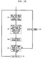
- FIG. 7a illustrates an exemplary method for measuring down-link interference.
- the base station 10 of a cell 5 (“the primary cell") directs a down-link beam toward a terminal 15 i in its cell.
- the beam generated by the base station 10 for this measurement is the "standard pattern" beam without the interference attenuating notches.
- the transmit power of the beam is adjusted so that the power received by the terminal 15 i conforms to the power control scheme for normal operation.
- Each terminal 15 within the cell's cluster measures the received signal strength, per operation block 203.
- Each of the receiving terminals reports its measurement to its respective cell controller 25, as indicated in operation block 205.
- the cell controller calculates the interferer to signal power ratio, if the data base values are to be expressed on this basis.
- Each cell controller 25 reports the results of the interference measurements to every cell controller in its cluster. This inter-cell communication is indicated in operation block 207.
- Decision block 209 queries whether the transmitting base station has transmitted to each terminal 15 in its cell. If not, the next terminal is selected, as indicated in operation block 211, and the base station of the primary cell transmits to that terminal. The received signal power measurements are repeated by all terminals in the cluster. In this manner, the base station 10 in the primary cell transmits to each terminal 15 in its cell 5, and each terminal 15 in the primary cell's cluster measures the received signal strength during such transmission. This completes the downlink measurements involving the base station 10 of the primary cell.
- the measurements for another cell can begin, as indicated in operation block 213.
- FIG. 7b A preferred embodiment of a method for measuring uplink interference is shown in FIG. 7b.
- a terminal 15 i in a cell 5, again the "primary cell” transmits to its base station, which directs a standard pattern uplink beam 20 toward that terminal.
- the transmit power of the terminal is adjusted so that the received power at the base station conforms with the power control scheme for normal operation.
- all other uplink beams 20 of the primary cell's cluster are directed to each of the terminals 15 within the respective cells of such beams, terminal by terminal, during the aformentioned transmission.
- the signal power received by an uplink beam when facing every terminal in its cell, due to the one transmitting terminal in the primary cell is measured and recorded.
- the standard radiation pattern of the base station antenna is used for measurements, and, if desired, the cell controller will express the measurement results as the normalized signal to interferer power ratio, i.e., interferer power to signal power.
- the cell controllers in the cluster share the measured information with the each cell controller within their cluster, per operation block 225.
- Decision block 227 queries whether every terminal within the primary cell has transmitted to its base station. If not, another terminal 15 within the primary cell is selected to transmit, as indicated in operation block 229, and the aforementioned signal power measurements are repeated. Such measurements continue until each terminal 15 within the primary cell has transmitted to the base station 10. Another cell then becomes the primary cell, as indicated in operation block 231, and the interference measurements continue.
- Azimuths of in-cell terminals stored in the data base 45 are preferably based on the actual angle of arrival of the strongest multipath replica of the desired signal traveling between a base station 10 and the terminal 15 i , not a map derived azimuth.
- the azimuth of an out-of-cell terminal is based on map-derived azimuths. While it may be desirable to store measured azimuths in preference to map-derived azimuths, obtaining such data would significantly complicate data acquisition. It is believed that such an approach is not presently practical due to theconcentrity of such a task. For smaller scale systems, however, it might be practical to measure the actual angle of arrival of the dominant interferer signal for any pair of a base station and in-cluster terminal.
- a TDM-based FWL system includes appropriate electronics and software for automatic database updating using time slots 35 allocated for such purpose for the duration of the measurements.
- each cell controller 25 maintains its own list of in-cell and in-cluster active links 46.
- the list 46 contains all active links in the given cell's cluster, the time slots allocated for the uplink and downlink, and an estimate of the interference-to-signal ratio (TI/S) or the inverse thereof experienced by the uplink receiver (located at the base station) and the downlink receiver (located at the terminal).
- TI/S interference-to-signal ratio
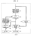
- the cell controller 25 calculates the S/TI for links within its cell using the data base entries, the current list of active links in its cluster and the actual radiation patterns generated to support each link within its cell. As to out-of-cell active links, the cell controller 25 relies on the other cell controllers in its cluster to provide it with the identity, allocated time slots and S/TIs of those links. Such inter-cell communication is required since the cell controller of a given cell cannot calculate the S/TI for a link in another cell since each cell has a distinct cluster. The aforementioned out-of-cell (but in-cluster) information is provided to the cell controller 25 by input data S3 in , as shown in FIG. 8.
- the cell controller 25 of a particular cell takes certain actions with respect to its list 46 when advised of changes in active links anywhere in its cluster. For example, the cell controller 25 may be advised, via input data S2, that a terminal within its cell is going off-the-air. In response, the cell controller deletes the uplink and downlink associated with the terminal from the list 46 as indicated by operation block S2P, recalculates the S/TI for all links in its cell as per operation block 121, and informs, via output data S3 out , other cell controllers in its cluster of the deletion and the revised S/TI values, as indicated in operation block 127. The cell controller may similarly receive data input S3 in , which may contain information pertaining to the addition or deletion of out-of-cell links.
- the controller updates the entries in its list 46, as indicated in operation block S3P in FIG. 8. It then recalculates the S/TI of its cell links as per operation block 121, and advises the rest of the controllers in its cluster about the updated values per operation block 127.
- a cell controller may optionally alter any of its same-slotted uplink beams, as indicated in operation block 123. Such alteration is for the purpose of minimizing interference caused by the new link.
- the cell controller then recalculates the S/TI for all same-slotted links within its cell.
- a controller may likewise decide to alter its same-slotted downlink beams, as indicated in operation block 125. Such alteration is for the purpose of protecting the new link.
- the cell controller will advise, via S3 out , the cell controllers in its cluster of the updated S/TI of the uplink beams, as indicated in operation block 127. In presently preferred embodiments, it will not, however, advise other cell controllers of adjustments in the S/TI of downlink beams. Such silence is for the purpose of limiting inter-controller data flow. It should be understood that in other less preferred embodiments, other cell controllers may be advised of adjustments in the S/TI of downlink beams.
- a cell controller While more readily apparent for the case in which a link is added, it is advantageous for a cell controller to alter its beams even for the case of an out-of-cell terminal going off-the-air. In altering its beams by deleting unnecessary notches, the cell controller facilitates generating new notches as required, thereby improving system capacity.
- a cell controller calculates the S/TI (or its inverse) for links within its cell, it uses the normalized signal to interference measurements from the data base. Since, as previously described, the data base measurements are obtained using standard radiation patterns, i.e., the beams used do not include interference mitigating notches, the calculated S/TI should be conservative.
- the cell controller 25 allocates a receive slot on an uplink beam 20 and a transmit slot on an downlink beam 21 if it finds suitable slots.
- the cell controller 25 utilizes information from its data base 45 and list of active links 46 in order to do so. Having described the data base 45 and list of active links 46, an exemplary method by which the cell controller allocates uplink and downlink slots can now be described.
- the cell controller estimates the S/TI at the base station receiver for the proposed link on a first time slot 35 i , as shown in operation block 131 of FIG. 9.
- the cell controller 25 takes into account the ability of the uplink beam former 40 within its cell 5 to generate a beam 20 with a plurality of suitably deep notches to attenuate interference from a small group containing the strongest interferers.
- the actual achievable interferer attenuation in terms of the ratio between the peak of the main lobe, such as the peak P1 shown in FIG. 5, and the level of the radiation pattern in the direction of the interferer, such as indicated at angular offsets AZ1 - AZ6, depends on many factors including, for example, the physical configuration of the antenna, the number of interferers the beam former 40 is trying to attenuate, the angular location of the interferers with respect to the main lobe, the relative power of each interferer, and the antenna tolerances, i.e., the extent by which the actual structure and electronic circuitry differ from the information known to the corresponding beam former. In particular, phase and amplitude drifts can significantly affect the depth and precise location of the notches produced.
- the cell controller 25 uses the aforementioned bound to calculate the expected S/TI at the base station receiver.
- the expected S/TI at the base station receiver based on the data base can be expressed as S/ [ ⁇ J i ], where S is the signal power and J i is the power received from the ith interferer when standard pattern beams are used.
- Notches can be implemented in certain directions in order to attenuate a selected group of strong interferers by using a factor ⁇ i .
- ⁇ i J i is the interference power remaining after the introduction of the notch.
- ⁇ i is easily determined for each notched out interferer.
- the resulting TI/S is thus [ ⁇ ⁇ i J i ]/S .
- the cell controller 25 calculates the radiation pattern using an exemplary method described later in this specification.
- the exemplary method determines an optimum "weighting vector" required to generate the beam and also calculates the S/TI.
- the cell controller 25 should allow some margin to account for electrical and mechanical errors that limit the achieveable "depth" of the calculated notches.
- the cell controller queries whether the revised S/TI for the base station receiver is greater than or equal to a threshold S/TI, i.e., the minimum S/TI for "acceptable" reception. If the new S/TI is less than the threshold value, the cell controller checks to see if all uplink slots have been checked, per decision block 134. If all slots have been checked, and none have been found acceptable per block 135, the request is rejected. If not, then the calculation is repeated for another slot, as indicated in operation block 136.
- a threshold S/TI i.e., the minimum S/TI for "acceptable" reception.
- the cell controller determines, in operation block 137, if adding the link affects other base stations that are already on-the-air on that slot to such an extent that the reception of at least one other link becomes unacceptable. This is accomplished by recalculating the S/TI for all active uplinks in the cluster. To perform this calculation, the cell controller 25 retrieves the S/TI of each of such active links from its list 46 and determiness the effect of the additional interference, based on the corresponding data base entry.
- the cell controller 25 does not rely on the ability of other base stations 10 to generate radiation pattern notches intended to minimize the interfering effect of the terminal 15 i .
- the reason for this is that other cell controllers cannot respond to such a request in "real time.”
- the cell controller 25 will approve a receive slot only if all of the out-of-cell active uplinks using that slot can sustain the additional expected interference before adjusting their current beam.
- the cell controllers of affected cells will, however, preferably reduce their received interference by altering their uplink beams 20 as previously noted in conjunction with the discussion of FIG. 8.
- Decision block 138 queries if the S/TI for all existing links is equal to or greater than a threshold value. If so, an uplink slot is found, per block 139. If the S/TI for one or more links is less than the threshold, then the time slot under consideration is rejected. If all time slots have been considered, then the request for service is denied. If additional time slots remain to be checked, the next slot is selected per operation block 136 and the S/TI for the time slot is calculated and processed as previously described.
- the cell controller 25 performs essentially the same steps when considering a downlink slot.
- the S/TI of the terminal receiver is calculated for a candidate time slot.
- the interference at the terminal receiver will be caused by other base stations.
- the cell controller will not rely on the ability of the controllers of such other base stations to alter their downlink beams by adding a notch for the benefit of the requesting terminal.
- the calculated S/TI is based on the data base.
- the cell controller further verifies that all of the terminals 15 in its cluster currently receiving on that slot can sustain the additional interference of the base station's transmission. For this calculation, the cell controller 25 calculates the affected S/TI values using values from the data base 45. If necessary, the cell controller can rely on the ability of its beam formers to generate a number of notches, the depth of which can be conservatively estimated using a bound.
- Beam forming has been referenced briefly a number of times above. A more detailed description of beam forming is now provided. It will be appreciated that the beam formers 40 must complete their calculations rapidly to avoid system delays. A dedicated powerful microprocessor may be required for each beam former.
- the cell controller 25 provides each beam former 40 with specific information required for beam forming. More particularly, to calculate the radiation pattern for a downlink beam 21 for transmission to a terminal 15 i , a beam former 40 is provided with:
- Both radiation pattern calculations can be calculated according to the exemplary methods described later in this specification.
- the calculations are very similar, a difference being that, for the downlink, the "quantity representing the relative importance of transmission suppression on each phase offset" must first be expressed as a "virtual interferer power" through a simple monotonically increasing conversion function.
- link A and link B both of which appear in the short list provided to the downlink beamformer 40. Reception on link A is marginal, while reception on link B is better, i.e., a higher S/TI ratio.
- the virtual interferer power corresponding to link A should result in a relatively deeper notch being formed in the direction of link A than the notch formed in the direction of link B. It should be understood that such a function is dependent upon the specific configuration of the base station antenna, among other considerations, and is selected by the antenna designer. Selection of such a function is within the capabilities of those skilled in the art.
- the result of the calculations is the weighting vector, W.
- the calculated vector is then stored and reused during the same time slot 35 in following frames 30. Note that a notch resulting from the beam forming calculations provides a S/TI at the receiver that is greater than or equal to the S/TI estimated during slot allocation using the lower bound signal to interference value.
- Beam forming operations are described in more detail in conjunction with FIGS. 11 - 14. To facilitate the description, the preferred configuration of the base station antenna will be provided. The terminal antenna is described, as well.
- the antenna located at each terminal 15 1-N is small, inexpensive and easy to install. Notwithstanding the desire for simplicity, in some embodiments, the terminal antenna is mechanically adjustable in such a way that a radiation dip can be realized in one or two directions. The reason for this is that a large portion of the interference power typically comes from a single source. Interference may thus be attenuated, albeit crudely, by an installation-time adjustment based on the geographic location of the base station that is expected to be the main source or object of interference.
- the terminal antenna is fabricated from two parts such that the spacing between the parts can be mechanically adjusted.
- Such an antenna will have a variable width main lobe bordering a notch that can be mechanically adjusted over a limited angular range.
- Other physical configurations for achieving the aforementioned objective will occur to those skilled in the art.
- the base station's antenna is considerably more complex than the terminal antenna.
- the base station's antenna is a phased array antenna capable of simultaneously generating N transmit beams and N receive beams.
- the transmit and receive beams are independently steerable in any direction in the horizontal plane under the control of a beam former 40.
- a beam maintains an approximately fixed beamwidth in the vertical plane.
- the beamwidth ranges from 15 to 20 degrees at the 3dB points. In areas that are flat, narrower vertical beams can advantageously be used.
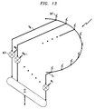
- the antenna of the base station 10 is preferably configured as a planar circular array having vertically-placed radiating elements attached to the surface of a virtual vertical cylinder of radius R. The centers of such radiators are aligned thereby defining a ring in the horizontal plane.
- Each radiating element can be, for example, a vertical colinear array of some basic radiator.
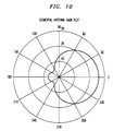
- An exemplary radiation pattern of a radiating element in the horizontal plane is shown in FIG. 10.
- the pattern shown in FIG. 10 is the measured pattern of a vertical array of four patch antennas. Antenna size is dictated, as a practical matter, by frequency, real estate and cost considerations. Configurations other than a planar circular array can suitably be used.
- the active radiators occupy a sector facing the direction of the desired beam, and are distributed approximately equally on either side of a line crossing the center of the circular structure pointing toward the desired direction of the main lobe.
- the sector including the active radiators is referred to herein as "the active sector" of the beam.
- the angular width, a, of the active sector is a free design parameter that should be optimized for the selected radiation pattern of the individual radiator and the number of radiators in the cylindrical array.
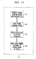
- a weighting vector, W is generated that optimizes the S/TI at the antenna output.
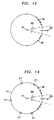
- a base station 10 antenna is located at the center of a large circle placed in a horizontal plane, as shown in FIG. 12.
- a large number, I, of equal power noise sources 301 are assumed to be equally spaced along the circumference of the circle, and such sources cover the complete circumference except for a clear window region 303 that is free of noise sources and has one signal source 305, which is the desired signal, located at the center of the region 303.
- the width of the clear window 303 is a design parameter to be optimized. Such optimization can be performed, for example, by using the exemplary calculation method for determining the optimal weighting vector described below for several values of window width and choosing the one yields the best S/TI.
- the optimal weighting vector is stored and later used in the same time slots 35 in following frames 30.
- the S/TI is calculated and provided to the cell controller 25, and, ultimately, to other cell controllers in the cluster.
- beam forming electronics described in conjunction with FIGS. 15- 17, generate the beam, per operation block 149.
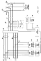
- FIG. 13 provides a conceptual illustration of how the weighting vector W is used to generate a beam.
- signals S 1 - S k received by K radiating antenna elements 307 are multiplied, using multipliers 423, by the corresponding component of the vector W and then summed to produce a radiation pattern that optimizes the S/TI at the antenna output.
- the method differs in that a virtual signal source is placed in the desired transmission direction and virtual interferers are placed in the directions in which interference generation is to be avoided.
- the power of the virtual interferers reflects the importance assigned to minimizing transmission in those directions.
- a beam former 40 In response to locating virtual interferers in certain directions, a beam former 40 generates a beam having notches in those directions.
- the depth of each notch reflects the power of the virtual interferer. It should be understood that while in theory notch depth (expressed in dB with reference to the beam's main lobe) is unlimited, in practice, notch depth is limited. In particular, notch depth is limited by the propagation irregularities such as multipath propagation, reflections from conducting objects, and the like. Also, as previously mentioned, notch depth is limited by antenna tolerances.
- the radiation pattern of each radiator in the horizontal plane is g( ⁇ ), where the array consists of K radiators arranged along a circular section.
- the signal voltage received by the complete array will be: where W k is the complex weight of the kth radiator.
- a small number of dominant interferers are assumed to exist, whose angular location and field intensity in the area where the antenna is located are precisely known.
- a large number of "background" interferers exsists.
- the background interferers are not individually accounted for. Rather, they are replaced, for beam synthesis purposes, with uniformly spaced equal power interference sources. All interferers are assumed uncorrelated.
- the total number of interferers is represented by I. Then the noise voltage received by the kth radiator is: And the total interference voltage is: The expected interference power is:
- a beam is generated by activating only one third of such elements.
- the 32 activated elements are located on a 120 degrees "horseshoe" facing the the location of the desired signal.
- the kth antenna element is therefore located at: 2 ⁇ (k-K/2-0.5)/(3K) radians
- the amount of calculations can be limited by dividing the interferers to two groups. The first group represents a small number of dominant interferers whose precise location and intensity are known. Such dominant interferers are accounted for on an individual basis.
- the second group of interferers is considered to be a large number of equal power interferers placed uniformly around the antenna keeping a "clear window" of w radians. All interferers are considered uncorrelated. All the interferers generate the same noise power, n j , which is arbitrarily chosen as 1.
- the angle between any two interferers is: (2 ⁇ -w)/I radians.
- the ith interferer is located at: w/2+(2 ⁇ -w)(i-0.5)/I
- g( ⁇ ) Cos 4 ( ⁇ /2)+0.17Cos 4 (( ⁇ - ⁇ )/2)-0.0568
- g( ⁇ ) Cos 4 ( ⁇ /2)+0.17Cos 4 (( ⁇ - ⁇ )/2)-0.0568
- the modified radiation pattern remains very close to the original (i.e., with no strong interferers) except at the "immediate vicinity" of a interferer, where a sharp notch appears.
- FIG. 5 shows the radiation pattern generated by the exemplary algorithm when 98 "weak” interferers (100 minus the 2 that were eliminated in order to generate the clear window) and in addition six “strong", equal power, interferers located as shown are specified.
- FIG. 14 shows the S/TI ratio when the power of the strong interferers is the independent variable. The signal power was first set in the absence of the strong interferers so that the resulting S/TI ratio obtained is 30 dB. It can be seen that when the antenna beam is adjusted to compensate for the increasing power of the "strong" interferers, as indicated by reference numeral 90, the S/TI ratio degrades very slowly, while when W is held fixed indicating no adjustment, as indicated by reference number 94, the S/TI degrades rapidly.
- calculating W opt involves inverting the matrix M, which is a square KxK matrix. If K is large, i.e., there are many radiators, this is a calculation intensive task. Once the matrix M is known, however, modifying it to add or delete a single interferer can be done using a simplified method.
- the short-cut method uses the following theorem:
- This method requires around 3K 2 + 2K multiplies.
- FIGS. 16-18 Block diagrams of some of the important signal receiving, beam generating and signal transmitting electronics of a base station 10 are shown in FIGS. 16-18. It should be understood that such block diagrams omit many components that are not essential for understanding the invention, e.g., filters, IF amplifiers and the like. It will be appreciated that illustrations are provided to facilitate understanding of the invention, not to limit its scope.
- FIG. 16 illustrates exemplary base station transmit (downlink) electronics for a multiple beam system according to the present invention.
- a number, N, of transmit modems 401 preferably operating at IF frequency, each provide a signal, S i , intended for transmission to a terminal 15.
- the number N is the number of transmit (downlink) beams DB1 - DBN.
- the signals S 1-N are provided, one each, to N power dividers 403.
- the power dividers 403 divide each signal S i into K channels C j .
- the N groups of K channels C j are sent to N banks of K multipliers 405.
- the multipliers multiply each channel C j by the appropriate one of K sine waves generated by N phase and amplitude controllers 429.
- the amplitude and phase of each sine wave is dictated by the appropriate component of the weighting vector W, which is calculated by one of the downlink beam formers 40a under the control of the cell controller 25.
- the resultant K channels CO j for each beam are sent to a downlink switching and summing matrix 407, which, under the control of the cell controller 25, routes each of the groups of K channels CO 1 - CO k into K contiguous possibly overlapping radiator channels CR 1 - CR k . All the radiator channels are fed to an up-converter 408.
- the up-converter 408 up-converts the output of the switching and summing matrix 407 to the transmit frequency.
- the up-converter comprises a bank of mixers 409, a power divider 433 and a local oscillator or synthesizer 431. Note that a common synthesizer 431 is used.
- the up-converted radiator channels are fed to a bank of M power amplifiers 411, one per radiator, where M is the total number of radiators comprising the phased array antenna.
- the amplified channels are sent to a bank of M diplexers 413, one per antenna radiator.
- the diplexers route the channels to the K active radiators 415.
- FIG. 17 illustrates exemplary receive (uplink) electronics for a multiple beam system according to the present invention.
- the signals received by the radiators 415 pass through the bank of diplexers 413 to a bank of M low noise amplifiers 417 and then to a down converter 418.
- the down-converter 418 down-converts the frequency of the received signals for processing in the switching and dividing matrix.
- the down-converter comprises a bank of mixers 419, a power divider 437 and a local oscillator or synthesizer 435. Again, the synthesizer 435 is common.
- the uplink switching and dividing matrix 421, under the control of the cell controller 25, routes the signals from N groups of K contiguous radiators to the appropriate beam electronics.
- N banks of K multipliers each multiply the K signals for each beam by the appropriate one of K sine waves generated by N phase and amplitude controllers 439.
- the amplitude and phase of each sine wave is dictated by the appropriate component of the weighting vector W, which is calculated by one of the uplink beam formers 40b under the control of the cell controller 25.
- the K signals comprising an uplink beam UB1 - UBN are fed to a power combiner 425, which feeds the combined signal to one of N receive modems 427.
- FIG. 18 shows an exemplary architecture of the phase and amplitude controllers.
- Each phase and amplitude controller 429, 439 includes K direct digital synthesizers (DDSs) 441.
- DDSs direct digital synthesizers
- Each DDS 441 generates a sine wave, the phase and amplitude of which is controlled by an appropriate one of K signals BFS 1-K for a given uplink or downlink beam generated by the respective beam formers 40b, 40a.
- the bank of K DDSs is clocked by a common clock line, CL, and reset by a common reset line, RL.
- Bandpass filters 443 ensure that the signal sent to the mixers 423 are clean of undesired spurious.
- Amplifiers 445 amplify the signals produced by the DDSs. 441.
- an adaptive beam may be implemented by using a closed-loop adaptation algorithm driven by the designated receiver of each receive beam.
- closed-loop adaptation algorithms are well known to those skilled in the art.
- Such a method might avoid the need for frequent calibrations of the base station's antenna system in order to counter possible drifts in the electronic circuitry supporting each individual radiator.
- Another feature of such a embodiment may be the ability of an adaptive beam to track temporal changes of links parameters.
Abstract
Description

(terminals) in cell A, nB links in cell B, through nFC links of the final cell of the cluster. Likewise, each other in-cell link, 2 through n, is paired with every in-cluster link.

- (i) the azimuth of the terminal 15i;
- (ii) a short list, which can be empty, of phase offsets to "null out;" and
- (iii) the anticipated power of every interferer in the short list, which is obtained from the data base 45.

This inner product can be written as a multiplication of two column vectors:


Since:

In this application, -δ ≤ Φ ≤ δ where 2δ is the angular separation between two radiators. When there is a need to steer a beam out of this limited range, a new active range is selected, i.e., some (possibly all) radiators are replaced by others.


The ith interferer is located at:
Substituting equations A15 and A16 into equation 1:

- M(k) is the matrix used after the kth step (i.e., following the inclusion/deletion of the jth interferer);
- M(k-1) is the matrix used in the (k-1)th step (i.e., the original matrix);
- βk = +1 if adding an interferer; βk = -1 if deleting an interferer.
- The new M matrix can be inverted as follows:
- M(k)-1 = M(k-1)-1 - λαYZ'
- Y = M(k-1)-1U; U=conj(S(Φj))
- Z' = V'M(K-1)-1 ; V=S'(Φj)
- λ = 1/(1+αZ'U) ; α=βknj 2
- Wk = M(k)-1conj(S(0))
Since: V = conj(U'); M = conj(M') and Z = conj(Y'),
the optimal vector can be calculated directly by determining the followiing quantities:
Claims (10)
- A method for beam forming, wherein the beam supports a communications link and wherein a specific group of strong interferers cause significant interference with and experience significant interference from the communications link, comprising the steps of:(A) retrieving data from storage pertaining to mutual interference levels experienced by and caused by the communications link, which data is periodically updated by interference measurements;(B) calculating a first optimal weighting vector that optimizes the signal to total interference ratio of an antenna beam at an antenna output based on the data retrieved in step (A), the first optimal weighting vector comprised of a number, K, of components, the number K being equal to a number of active radiating antenna elements involved in forming the antenna beam; and(C) multiplying each one of a plurality of signals received from or intended for each one of the K active radiating antenna elements by a corresponding component of the first optimal weighting vector.
- The method of claim 1 wherein, in step (A), a cell controller retrieves the data from storage and provides it to beam formers.
- The method of claim 2 wherein, in step (B), the beam formers calculate the first optimal weighting vector.
- The method of claim 3 wherein step (B) further comprises generating a plurality of sine waves corresponding in number to the plurality of signals, wherein, the amplitude and phase of each sine wave is determined by the corresponding component of the first optimal weighting vector.
- The method of claim 1 wherein, in step (B), the first optimal weighting vector, Wopt , is calculated according to the expression:M is the covariance matrix of the interference sources;S(Φ) is a vector, each component of which corresponds to a signal received by or delivered to one of the active radiating antenna elements; andΦ is the direction of the desired main lobe.
- The method of claim 5 wherein, after calculating the first optimal weighting vector, one interferer is added to or substracted from the specific group of interferers, and a second optimal weighting vector is calculated based on the first optimal weighting vector according to the expression:W(k) is the optimal weighting vector after accounting for the one interferer;W(k-1) is the first optimal weighting vector,M(k) -1 = M(k-1)-1 - λαYconj(Y'), λ = 1/[1 + αconj(Y')U], Y = M(k-1)-1U, α = βknj 2 ,U = conj(S(Φj), S(Φj) = [S1(Φj) S2(Φj) ... SK(Φj)]' ,S(Φj) is a vector, each component of which corresponds to a signal received by or delivered to one of the active radiating antenna elements,Φj = azimuth of the interferer,conj(S) is the complex conjugate of S.βk = +1 if one interferer is added and -1 if one interferer is substracted, andnj 2 is the power of the interferer.
- A computer-readable storage medium comprising encoded computer-readable program instructions for use in conjunction with a programmable computer, which instructions cause the computer to calculate a first optimal weighting vector, which, when multiplied by corresponding signals received from or delivered to radiators of a phased-array antenna, optimizes a signal to total interference ratio of an antenna beam generated by the phased-array antenna.
- The computer-readable storage medium of claim 7 further comprising encoded computer-readable program instructions that cause the computer to rapidly calculate a second optimal weighting vector using information developed during the calculation of the first optimal weighting vector and information pertaining to the addition or deletion of one interferer to a group of other interferers upon which the first optimal weighting vector calculation was based.
- A method for generating an uplink beam at a base station to facilitate a terminal's uplink transmission to the base station in a first communications link, comprising the steps of:(A) receiving a request to generate the uplink beam in a first time slot allotted to the first communications link based on interference caused by and experienced by the uplink of the first communications link;(B) obtaining the terminal's azimuth, a list of phase offsets, measured with reference to a main lobe of the uplink beam, corresponding to the received direction of interference from interferers, and further receiving the anticipated power of every interferer represented in the list of phase offsets; and(C) generating a beam with notches for attenuating the interference received from the interferers.
- The method of claim 9 further comprising generating a downlink beam at the base station to facilitate the base station's transmission to the terminal, comprising the steps of:(D) receiving a request to generate the downlink beam in a second time slot allotted to the first communications link based on interference caused by and experienced by the downlink of the first communications link;(E) obtaining the terminal's azimuth, a list of phase offsets to avoid, and further receiving a quantity representative of the relative importance of transmission suppression on each phase offset; and(F) generating a beam with notches for attenuating the signal transmitted toward the phase offsets listed in step (E).
Applications Claiming Priority (2)
| Application Number | Priority Date | Filing Date | Title |
|---|---|---|---|
| US745392 | 1996-11-08 | ||
| US08/745,392 US5914946A (en) | 1996-11-08 | 1996-11-08 | TDM-based fixed wireless loop system |
Publications (2)
| Publication Number | Publication Date |
|---|---|
| EP0843494A2 true EP0843494A2 (en) | 1998-05-20 |
| EP0843494A3 EP0843494A3 (en) | 2000-01-12 |
Family
ID=24996498
Family Applications (1)
| Application Number | Title | Priority Date | Filing Date |
|---|---|---|---|
| EP97308586A Withdrawn EP0843494A3 (en) | 1996-11-08 | 1997-10-28 | TDM-based fixed wireless loop system and method for beam forming |
Country Status (4)
| Country | Link |
|---|---|
| US (1) | US5914946A (en) |
| EP (1) | EP0843494A3 (en) |
| JP (1) | JP3086863B2 (en) |
| CA (1) | CA2216675C (en) |
Cited By (11)
| Publication number | Priority date | Publication date | Assignee | Title |
|---|---|---|---|---|
| WO2000035145A2 (en) * | 1998-12-07 | 2000-06-15 | Marconi Communications Israel Ltd. | Wireless local loop system and methods useful therefor |
| EP1075157A1 (en) * | 1999-02-16 | 2001-02-07 | Ntt Mobile Communications Network Inc. | Radio line allocation judging method in mobile communication system and radio line controller |
| FR2821513A1 (en) * | 2001-02-28 | 2002-08-30 | Jacques Lewiner | LOCAL RADIO COMMUNICATION SYSTEM |
| US7110759B2 (en) | 2001-02-28 | 2006-09-19 | Inventel Systems | Local radio communication system |
| EP1748664A2 (en) * | 2005-07-25 | 2007-01-31 | NTT DoCoMo INC. | Wireless control apparatus and communication method |
| EP2337418A1 (en) * | 2009-12-18 | 2011-06-22 | Alcatel Lucent | Dynamically scheduling connections of mobile stations in neighbouring cells in a mobile telecommunication network |
| EP2363967A4 (en) * | 2008-10-20 | 2016-10-19 | China Academy Of Telecomm Tech | Method and device for determining mobile communication interference source |
| WO2018048331A1 (en) * | 2016-09-06 | 2018-03-15 | Telefonaktiebolaget Lm Ericsson (Publ) | Resource configuration of wireless devices |
| US10524273B2 (en) | 2016-09-06 | 2019-12-31 | Telefonaktiebolaget Lm Ericsson (Publ) | Resource configuration of wireless devices |
| US11063795B2 (en) | 2016-11-16 | 2021-07-13 | Telefonaktiebolaget Lm Ericsson (Publ) | Methods and devices for adapting load on a fronthaul network |
| US11128322B2 (en) | 2016-09-06 | 2021-09-21 | Telefonaktiebolaget Lm Ericsson (Publ) | Methods and devices for determination of beamforming information |
Families Citing this family (61)
| Publication number | Priority date | Publication date | Assignee | Title |
|---|---|---|---|---|
| FI106668B (en) * | 1995-05-24 | 2001-03-15 | Nokia Networks Oy | Base station equipment and method for directing antenna beam |
| JP3204111B2 (en) * | 1996-08-28 | 2001-09-04 | 松下電器産業株式会社 | Directivity control antenna device |
| US7035661B1 (en) * | 1996-10-11 | 2006-04-25 | Arraycomm, Llc. | Power control with signal quality estimation for smart antenna communication systems |
| US6275543B1 (en) | 1996-10-11 | 2001-08-14 | Arraycomm, Inc. | Method for reference signal generation in the presence of frequency offsets in a communications station with spatial processing |
| US6463295B1 (en) | 1996-10-11 | 2002-10-08 | Arraycomm, Inc. | Power control with signal quality estimation for smart antenna communication systems |
| US6144652A (en) * | 1996-11-08 | 2000-11-07 | Lucent Technologies Inc. | TDM-based fixed wireless loop system |
| US6002935A (en) * | 1997-05-22 | 1999-12-14 | At&T Corp | Wireless communications cellular architecture for improving communications resource allocation |
| FR2764140B1 (en) * | 1997-05-28 | 1999-08-06 | Armand Levy | COMMUNICATION METHOD BETWEEN AN ANTENNA BASE STATION AND A MOBILE AND BASE STATION FOR CARRYING OUT THIS METHOD |
| US6463301B1 (en) * | 1997-11-17 | 2002-10-08 | Nortel Networks Limited | Base stations for use in cellular communications systems |
| US6952585B1 (en) * | 1997-11-19 | 2005-10-04 | Ericsson Inc. | Multi-channel communication system for wireless local loop communication |
| US6185440B1 (en) * | 1997-12-10 | 2001-02-06 | Arraycomm, Inc. | Method for sequentially transmitting a downlink signal from a communication station that has an antenna array to achieve an omnidirectional radiation |
| US7299071B1 (en) * | 1997-12-10 | 2007-11-20 | Arraycomm, Llc | Downlink broadcasting by sequential transmissions from a communication station having an antenna array |
| US6289211B1 (en) * | 1998-03-26 | 2001-09-11 | Erksson Inc | Method for determining the position of a mobile station |
| JP3323438B2 (en) * | 1998-03-27 | 2002-09-09 | 松下電器産業株式会社 | Wireless communication system and wireless communication method |
| US6349217B1 (en) * | 1998-04-24 | 2002-02-19 | Lucent Technologies Inc. | Multi-mode/multi-rate fixed wireless communication system |
| US6615024B1 (en) | 1998-05-01 | 2003-09-02 | Arraycomm, Inc. | Method and apparatus for determining signatures for calibrating a communication station having an antenna array |
| US6766166B1 (en) * | 1998-09-23 | 2004-07-20 | Mobile Communications Holdings, Inc. | Antenna null |
| US6438741B1 (en) | 1998-09-28 | 2002-08-20 | Compaq Computer Corporation | System and method for eliminating compile time explosion in a top down rule based system using selective sampling |
| WO2000027139A1 (en) * | 1998-10-30 | 2000-05-11 | Motorola Inc. | Method and point-to-multipoint communication system utilizing optimized communication vectors |
| US6360094B1 (en) * | 1998-12-21 | 2002-03-19 | Nortel Networks Limited | Method for locating antenna problems in a cellular communications network |
| US6205441B1 (en) * | 1999-03-31 | 2001-03-20 | Compaq Computer Corporation | System and method for reducing compile time in a top down rule based system using rule heuristics based upon the predicted resulting data flow |
| US6600914B2 (en) | 1999-05-24 | 2003-07-29 | Arraycomm, Inc. | System and method for emergency call channel allocation |
| US7139592B2 (en) * | 1999-06-21 | 2006-11-21 | Arraycomm Llc | Null deepening for an adaptive antenna based communication station |
| US6804211B1 (en) | 1999-08-03 | 2004-10-12 | Wi-Lan Inc. | Frame structure for an adaptive modulation wireless communication system |
| US6778507B1 (en) * | 1999-09-01 | 2004-08-17 | Qualcomm Incorporated | Method and apparatus for beamforming in a wireless communication system |
| US6775551B1 (en) | 1999-12-30 | 2004-08-10 | Bellsouth Intellectual Property Corporation | Method and apparatus for fixing the location of a fixed wireless terminal in a wireless network |
| US6775552B2 (en) | 1999-12-30 | 2004-08-10 | Bellsouth Intellectual Property Corporation | Method and apparatus for fixing the location of a fixed wireless terminal in a wireless network |
| FI19992829A (en) * | 1999-12-30 | 2001-07-01 | Nokia Networks Oy | Transmission of data in a radio system from transmitter to receiver |
| US6968469B1 (en) | 2000-06-16 | 2005-11-22 | Transmeta Corporation | System and method for preserving internal processor context when the processor is powered down and restoring the internal processor context when processor is restored |
| US6771969B1 (en) | 2000-07-06 | 2004-08-03 | Harris Corporation | Apparatus and method for tracking and communicating with a mobile radio unit |
| KR20020010023A (en) * | 2000-07-28 | 2002-02-02 | 윤종용 | Adaptive beamforming method for application to code division multiple access wireless communication system |
| JP3530118B2 (en) * | 2000-08-29 | 2004-05-24 | 松下電器産業株式会社 | Base station apparatus and wireless communication method |
| US7460835B1 (en) * | 2000-09-22 | 2008-12-02 | Arraycomm Llc | Method and apparatus for determining an operating condition in a communications system |
| US6795409B1 (en) | 2000-09-29 | 2004-09-21 | Arraycomm, Inc. | Cooperative polling in a wireless data communication system having smart antenna processing |
| CA2899094C (en) | 2000-11-15 | 2016-08-30 | An Chen | Improved frame structure for a communication system using adaptive modulation |
| US6711416B1 (en) | 2000-11-28 | 2004-03-23 | Hongliang Zhang | Fixed wireless communication system having power control for downlink data traffic |
| US6947748B2 (en) | 2000-12-15 | 2005-09-20 | Adaptix, Inc. | OFDMA with adaptive subcarrier-cluster configuration and selective loading |
| US7031652B2 (en) * | 2001-02-05 | 2006-04-18 | Soma Networks, Inc. | Wireless local loop antenna |
| JP2002271266A (en) * | 2001-03-09 | 2002-09-20 | Nec Corp | Cdma base station, and transmission diversity control method |
| KR20020091791A (en) * | 2001-05-30 | 2002-12-06 | 미츠비시 마테리알 가부시키가이샤 | Communication system management server, wireless server, mobile management server and information management server |
| JP4754103B2 (en) * | 2001-06-26 | 2011-08-24 | Kddi株式会社 | Radio base station apparatus and transmission destination mobile device selection method thereof |
| US20030017853A1 (en) * | 2001-07-12 | 2003-01-23 | Sarnoff Corporation | Method and apparatus for enhancing the data transmission capacity of a wireless communication system |
| FI20012473A (en) * | 2001-12-14 | 2003-06-15 | Nokia Corp | Procedure for controlling a broadcast in a radio system |
| JP4178501B2 (en) * | 2002-05-21 | 2008-11-12 | 日本電気株式会社 | Antenna transmission / reception system |
| US7046655B2 (en) * | 2002-08-15 | 2006-05-16 | Interdigital Technology Corporation | Wireless communication method and system for minimizing interference by determining mobile station zone locations and potential conflicts between cell zones |
| AU2003285138A1 (en) | 2002-11-04 | 2004-06-07 | Vivato Inc | Directed wireless communication |
| EP2587686B1 (en) * | 2002-11-08 | 2017-01-04 | Innovative Wireless Sweden AB | Adaptive broadband platforms and methods of operation |
| US7379506B2 (en) * | 2003-09-23 | 2008-05-27 | Nokia Corporation | Apparatus, and associated method, for assigning data to transmit antennas of a multiple transmit antenna transmitter |
| US7437166B2 (en) * | 2003-09-24 | 2008-10-14 | Telefonaktiebolaget Lm Ericsson (Publ) | Reducing shared downlink radio channel interference by transmitting to multiple mobiles using multiple antenna beams |
| US7853215B2 (en) * | 2003-10-10 | 2010-12-14 | Motorola, Inc. | Communication circuit and method for selecting a reference link |
| US7573851B2 (en) | 2004-12-07 | 2009-08-11 | Adaptix, Inc. | Method and system for switching antenna and channel assignments in broadband wireless networks |
| US20070014307A1 (en) * | 2005-07-14 | 2007-01-18 | Yahoo! Inc. | Content router forwarding |
| US7689162B2 (en) * | 2005-10-28 | 2010-03-30 | Viasat, Inc. | Adaptive coding and modulation flow control and traffic shaping systems and methods |
| US7986624B2 (en) * | 2005-10-28 | 2011-07-26 | Viasat, Inc. | Quality of service enhancements for adaptive coding and modulation |
| US7782754B2 (en) * | 2006-12-28 | 2010-08-24 | Intel Corporation | Method and apparatus to support SDMA transmission of a OFDMA based network |
| WO2008100191A1 (en) * | 2007-02-16 | 2008-08-21 | Telefonaktiebolaget Lm Ericsson (Publ) | Method for repetitive transmissions |
| BRPI0911586A2 (en) * | 2008-05-02 | 2016-01-05 | Spx Corp | super economical broadcast system and method |
| US20120077504A1 (en) * | 2008-05-02 | 2012-03-29 | Spx Corporation | Super Economical Broadcast System |
| US8611331B2 (en) * | 2009-02-27 | 2013-12-17 | Qualcomm Incorporated | Time division duplexing (TDD) configuration for access point base stations |
| US8699982B2 (en) * | 2012-03-27 | 2014-04-15 | Adc Telecommunications, Inc. | Systems and methods for implementing a distributed antenna system in a radio frequency integrated circuit |
| WO2017006470A1 (en) * | 2015-07-08 | 2017-01-12 | 三菱電機株式会社 | Communication device and beam selection method |
Citations (4)
| Publication number | Priority date | Publication date | Assignee | Title |
|---|---|---|---|---|
| WO1986001057A1 (en) * | 1984-07-23 | 1986-02-13 | The Commonwealth Of Australia Care Of The Secretar | Adaptive antenna array |
| US5260968A (en) * | 1992-06-23 | 1993-11-09 | The Regents Of The University Of California | Method and apparatus for multiplexing communications signals through blind adaptive spatial filtering |
| GB2266998A (en) * | 1992-05-11 | 1993-11-17 | Motorola Inc | Beam pattern equalization method for an adaptive array |
| WO1996022662A1 (en) * | 1995-01-20 | 1996-07-25 | Arraycomm, Inc. | Spectrally efficient high capacity wireless communication systems |
Family Cites Families (4)
| Publication number | Priority date | Publication date | Assignee | Title |
|---|---|---|---|---|
| US5448753A (en) * | 1988-09-05 | 1995-09-05 | Ahl; Karl-Axel | Wide area radio communication network system and method |
| SE8903455D0 (en) * | 1989-10-19 | 1989-10-19 | Joakim Nelson | DYNAMIC DIGITAL CONNECTION UNIT (DFN) |
| US5515378A (en) * | 1991-12-12 | 1996-05-07 | Arraycomm, Inc. | Spatial division multiple access wireless communication systems |
| US5742252A (en) * | 1996-08-26 | 1998-04-21 | Raytheon Company | Ambiguity resolving algorithm for interferometers of arbitray topologies |
-
1996
- 1996-11-08 US US08/745,392 patent/US5914946A/en not_active Expired - Lifetime
-
1997
- 1997-09-29 CA CA002216675A patent/CA2216675C/en not_active Expired - Fee Related
- 1997-10-28 EP EP97308586A patent/EP0843494A3/en not_active Withdrawn
- 1997-10-31 JP JP09301117A patent/JP3086863B2/en not_active Expired - Fee Related
Patent Citations (4)
| Publication number | Priority date | Publication date | Assignee | Title |
|---|---|---|---|---|
| WO1986001057A1 (en) * | 1984-07-23 | 1986-02-13 | The Commonwealth Of Australia Care Of The Secretar | Adaptive antenna array |
| GB2266998A (en) * | 1992-05-11 | 1993-11-17 | Motorola Inc | Beam pattern equalization method for an adaptive array |
| US5260968A (en) * | 1992-06-23 | 1993-11-09 | The Regents Of The University Of California | Method and apparatus for multiplexing communications signals through blind adaptive spatial filtering |
| WO1996022662A1 (en) * | 1995-01-20 | 1996-07-25 | Arraycomm, Inc. | Spectrally efficient high capacity wireless communication systems |
Non-Patent Citations (1)
| Title |
|---|
| VAN VEEN ET AL.: "Beamforming:A Versatile Approach to Spatial Filtering" IEEE ACOUSTICS,SPEECH, AND SIGNAL PROCESSING MAGAZINE,US,IEEE INC., vol. 5, no. 2, 1 April 1988 (1988-04-01), pages 4-24, XP002050877 New York * |
Cited By (24)
| Publication number | Priority date | Publication date | Assignee | Title |
|---|---|---|---|---|
| WO2000035145A3 (en) * | 1998-12-07 | 2000-10-19 | Marconi Communications Israel | Wireless local loop system and methods useful therefor |
| WO2000035145A2 (en) * | 1998-12-07 | 2000-06-15 | Marconi Communications Israel Ltd. | Wireless local loop system and methods useful therefor |
| EP1075157A1 (en) * | 1999-02-16 | 2001-02-07 | Ntt Mobile Communications Network Inc. | Radio line allocation judging method in mobile communication system and radio line controller |
| EP1075157A4 (en) * | 1999-02-16 | 2005-09-14 | Nippon Telegraph & Telephone | Radio line allocation judging method in mobile communication system and radio line controller |
| EP1653757A1 (en) * | 1999-02-16 | 2006-05-03 | Ntt Mobile Communications Network Inc. | Radio line allocation judging method in a mobile communication system and radio line controller |
| FR2821513A1 (en) * | 2001-02-28 | 2002-08-30 | Jacques Lewiner | LOCAL RADIO COMMUNICATION SYSTEM |
| WO2002069658A1 (en) * | 2001-02-28 | 2002-09-06 | Jacques Lewiner | Local radio communication system |
| US7110759B2 (en) | 2001-02-28 | 2006-09-19 | Inventel Systems | Local radio communication system |
| US8229418B2 (en) | 2005-07-25 | 2012-07-24 | Ntt Docomo, Inc. | Wireless control apparatus and communication method |
| EP1748664A2 (en) * | 2005-07-25 | 2007-01-31 | NTT DoCoMo INC. | Wireless control apparatus and communication method |
| EP1748664A3 (en) * | 2005-07-25 | 2011-07-06 | NTT DoCoMo, Inc. | Wireless control apparatus and communication method |
| EP2363967A4 (en) * | 2008-10-20 | 2016-10-19 | China Academy Of Telecomm Tech | Method and device for determining mobile communication interference source |
| EP2337418A1 (en) * | 2009-12-18 | 2011-06-22 | Alcatel Lucent | Dynamically scheduling connections of mobile stations in neighbouring cells in a mobile telecommunication network |
| WO2018048331A1 (en) * | 2016-09-06 | 2018-03-15 | Telefonaktiebolaget Lm Ericsson (Publ) | Resource configuration of wireless devices |
| US10368362B2 (en) | 2016-09-06 | 2019-07-30 | Telefonaktiebolaget Lm Ericsson (Publ) | Configuration of transmission order of uplink data |
| US10420122B2 (en) | 2016-09-06 | 2019-09-17 | Telefonaktiebolaget Lm Ericsson (Publ) | Configuration of resolution of uplink data |
| US10524273B2 (en) | 2016-09-06 | 2019-12-31 | Telefonaktiebolaget Lm Ericsson (Publ) | Resource configuration of wireless devices |
| US10524274B2 (en) | 2016-09-06 | 2019-12-31 | Telefonaktiebolaget Lm Ericsson (Publ) | Configuration of a radio equipment of an access node |
| US10820334B2 (en) | 2016-09-06 | 2020-10-27 | Telefonaktiebolaget Lm Ericsson (Publ) | Configuration of resolution of uplink data |
| US11128322B2 (en) | 2016-09-06 | 2021-09-21 | Telefonaktiebolaget Lm Ericsson (Publ) | Methods and devices for determination of beamforming information |
| US11206675B2 (en) | 2016-09-06 | 2021-12-21 | Telefonaktiebolaget Lm Ericsson (Publ) | Configuration of transmission order of uplink data |
| US11690059B2 (en) | 2016-09-06 | 2023-06-27 | Telefonaktiebolaget Lm Ericsson (Publ) | Configuration of transmission order of uplink data |
| EP4271093A3 (en) * | 2016-09-06 | 2024-01-24 | Telefonaktiebolaget LM Ericsson (publ) | Resource configuration of wireless devices |
| US11063795B2 (en) | 2016-11-16 | 2021-07-13 | Telefonaktiebolaget Lm Ericsson (Publ) | Methods and devices for adapting load on a fronthaul network |
Also Published As
| Publication number | Publication date |
|---|---|
| JP3086863B2 (en) | 2000-09-11 |
| EP0843494A3 (en) | 2000-01-12 |
| JPH10190569A (en) | 1998-07-21 |
| CA2216675C (en) | 2001-11-20 |
| CA2216675A1 (en) | 1998-05-08 |
| US5914946A (en) | 1999-06-22 |
Similar Documents
| Publication | Publication Date | Title |
|---|---|---|
| US5914946A (en) | TDM-based fixed wireless loop system | |
| US6144652A (en) | TDM-based fixed wireless loop system | |
| CA2216761C (en) | Tdm-based fixed wireless loop system | |
| US7120431B1 (en) | System and method for adjusting antenna radiation in a wireless network | |
| US8548481B2 (en) | Systems and methods for coordinating the coverage and capacity of a wireless base station | |
| US6915133B2 (en) | Wireless communications cellular architecture for improving communications resource allocation | |
| US7805144B2 (en) | Channel assignment based on spatial strategies in a wireless network using adaptive antenna arrays | |
| JP2009033717A (en) | Resource allocation method and communication apparatus | |
| JPS6221299B2 (en) | ||
| GB2376568A (en) | Smart antenna array with physical periodicity | |
| US6415131B1 (en) | DMA cellular radio system with a channel quality criterion | |
| KR20060081194A (en) | Apparatus and method for configuration of sector in antenna array system | |
| GB2309858A (en) | Channel Allocation in a Space Division Multiple Access Radio Communication System | |
| US20050094602A1 (en) | System and method for providing multi-beam scheduling | |
| JP2002112328A (en) | Mobile communication network provided with enhanced downlink capacity | |
| JPH08509111A (en) | Radiotelephone system with reduced interference between channels using geographical separation of signals and communication power control | |
| CN115314081B (en) | Space resource management and optimization method for low-orbit communication satellite | |
| GB2328841A (en) | Means of increasing capacity in cellular radio (mobile and fixed) systems | |
| MXPA98004213A (en) | Means to increase capacity in radiocellular systems (moviles and fij |
Legal Events
| Date | Code | Title | Description |
|---|---|---|---|
| PUAI | Public reference made under article 153(3) epc to a published international application that has entered the european phase |
Free format text: ORIGINAL CODE: 0009012 |
|
| AK | Designated contracting states |
Kind code of ref document: A2 Designated state(s): DE FI FR GB NL SE |
|
| AX | Request for extension of the european patent |
Free format text: AL;LT;LV;RO;SI |
|
| PUAL | Search report despatched |
Free format text: ORIGINAL CODE: 0009013 |
|
| AK | Designated contracting states |
Kind code of ref document: A3 Designated state(s): AT BE CH DE DK ES FI FR GB GR IE IT LI LU MC NL PT SE |
|
| AX | Request for extension of the european patent |
Free format text: AL;LT;LV;RO;SI |
|
| RIC1 | Information provided on ipc code assigned before grant |
Free format text: 7H 04Q 7/20 A, 7H 04Q 7/36 B, 7H 01Q 3/26 B |
|
| 17P | Request for examination filed |
Effective date: 20000630 |
|
| AKX | Designation fees paid |
Free format text: DE FI FR GB NL SE |
|
| 17Q | First examination report despatched |
Effective date: 20050928 |
|
| RAP3 | Party data changed (applicant data changed or rights of an application transferred) |
Owner name: LUCENT TECHNOLOGIES INC. |
|
| STAA | Information on the status of an ep patent application or granted ep patent |
Free format text: STATUS: THE APPLICATION IS DEEMED TO BE WITHDRAWN |
|
| 18D | Application deemed to be withdrawn |
Effective date: 20100211 |