EP0847345B1 - Vorrichtung zum erfassen einer benetzung einer scheibe - Google Patents
Vorrichtung zum erfassen einer benetzung einer scheibe Download PDFInfo
- Publication number
- EP0847345B1 EP0847345B1 EP97924888A EP97924888A EP0847345B1 EP 0847345 B1 EP0847345 B1 EP 0847345B1 EP 97924888 A EP97924888 A EP 97924888A EP 97924888 A EP97924888 A EP 97924888A EP 0847345 B1 EP0847345 B1 EP 0847345B1
- Authority
- EP
- European Patent Office
- Prior art keywords
- light
- extraneous light
- change
- extraneous
- former
- Prior art date
- Legal status (The legal status is an assumption and is not a legal conclusion. Google has not performed a legal analysis and makes no representation as to the accuracy of the status listed.)
- Expired - Lifetime
Links
Images
Classifications
-
- B—PERFORMING OPERATIONS; TRANSPORTING
- B60—VEHICLES IN GENERAL
- B60S—SERVICING, CLEANING, REPAIRING, SUPPORTING, LIFTING, OR MANOEUVRING OF VEHICLES, NOT OTHERWISE PROVIDED FOR
- B60S1/00—Cleaning of vehicles
- B60S1/02—Cleaning windscreens, windows or optical devices
- B60S1/04—Wipers or the like, e.g. scrapers
- B60S1/06—Wipers or the like, e.g. scrapers characterised by the drive
- B60S1/08—Wipers or the like, e.g. scrapers characterised by the drive electrically driven
- B60S1/0818—Wipers or the like, e.g. scrapers characterised by the drive electrically driven including control systems responsive to external conditions, e.g. by detection of moisture, dirt or the like
Definitions
- the invention relates to a device for detection a wetting of a disc with the features contained in the preamble of claim 1.
- a device of this kind is in EP-B-0 460 180 specified.
- this known device by Sampling the output signal of a light receiver in one first interval the total light from the light of the transmitter and from ambient light in the area and in a narrow space related to the first interval second Interval only the extraneous light is detected.
- the evaluation level in The form of a microcontroller has an analog / digital converter and a timer.
- one Differential amplifier becomes a differential summation made to form a useful light signal. This device to obtain the useful signal is relatively complex.
- the invention has for its object a device of the aforementioned Provide type in which the useful light signal with simple measures won and the wetting of a disc is reliably detected.
- the measuring circuit has an integration stage for Detection of the amount of light of the light falling on the receiver and a comparator stage has with which a trigger signal can be emitted when the ab a certain threshold integrated light quantity at a certain point in time exceeds that from the light of the transmitter and any extraneous light existing total amount of light and that detected when the transmitter is switched off
- the amount of extraneous light can be measured at separate time intervals, the during the integration period until the trigger signal arrives, the count value generated is detected at Determine a size for the total light quantity and for the extraneous light quantity or for changing it
- Reciprocal value generator is provided for forming the reciprocal values of the respective count values and that the reciprocal values can be supplied to the difference generator.
- the integration stage for example a capacitor
- the integration time can be discharged via an electronic switch, and until the total light quantity can be obtained to reach the threshold as well as the amount of extraneous light reliably recorded at separate intervals be, with the integration and the common measuring device Interference can be suppressed.
- the reciprocal values from the count values and from the difference of the quantities thus obtained for the total amount of light and for the amount of extraneous light the useful light signal is obtained, too Processing effort to provide the useful light signal low .
- the Evaluation circuit can e.g. a relatively simple microcontroller is used become.
- the Total light quantity is measured recurrently, while the extraneous light quantity initially and subsequently only when the amount of extraneous light changes a predetermined amount is measured and stored, and that for determination of the useful light signal the currently stored amount of extraneous light is used becomes.
- To record the total amount of light or a corresponding one Size is measured recurrently, so that the resulting from wetting Information is captured safely because of the current wetting sensors comparatively good extraneous light compensation, extraneous light changes occur only occasionally.
- the amount of extraneous light is therefore sufficient once captured by the transmitter when the device is activated electronically controlled for the measurement interval is turned off, and after that just measure the amount of extraneous light when there is a change the amount of extraneous light is determined by a predetermined amount.
- the useful light signal becomes the current, stored amount of extraneous light offset against the total amount of light measured.
- a comparator is connected between the reciprocal value generator and the difference generator is and that the change in the amount of extraneous light by means of the comparator can be determined from the total amount of light by changing the total amount of light is detected with respect to a predetermined value.
- a change in The amount of extraneous light shows up in the total amount of light, so that a change in The amount of extraneous light is certainly detected.
- Another way to determine a change in the amount of extraneous light is in that the count of the extraneous light measurement before the complex division is monitored and only when a predetermined threshold is exceeded the division for detecting the amount of extraneous light is carried out.
- the reciprocal value generator has a weighting of the reciprocal value with a conversion factor on the order of 10,000 and makes 100,000.
- the conversion factor is 65535, i.e. in hexadecimal notation FFFF, This factor is favorable for the usual 16-bit division. On In this way, a number for the respective quantity of light can be avoided.
- An advantageous detection of wetting for example for automatic Activation of a windshield wiper in the rain or impinging dirt is that the total light measurement at intervals of a few milliseconds is carried out and that the resolution of the timer agree Is microseconds.
- the change in the amount of extraneous light can be calculated and that the so formed (actually from a portion of useful light and a portion of extraneous light existing) useful light signal by subtracting the change in the amount of extraneous light is formed from the total amount of light.
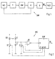
- Fig. 1 shows a block diagram for a device for detecting a wetting a disc with a wetting sensor.
- the wetting sensor has a measuring circuit MS to which an evaluation device or evaluation circuit with a timer T, a reciprocal KW, one Comparator K and a difference generator D is connected.
- the difference maker D gives a useful light signal NL formed in the evaluation circuit AW from z. B. via a wiper control WST a wiper to control corresponding wetting events.
- Fig. 2 shows an example of the measuring circuit MS.
- a transmitter diode SD emits light through an optical path into which the disk is coupled to a receiver E.
- a capacitor C is connected to the receiver as an integration stage against ground.
- a switch S1 is connected to ground in parallel with the capacitor C.
- a comparator stage K1 its output with an input 11 of the evaluation circuit AW, for example a microcontroller.
- the other entrance to the Comparator stage K1 is connected to an output A1 of the evaluation circuit AW.
- Another output of the evaluation circuit AW is on the switch S1 connected, while a third output A3 of the evaluation circuit AW is connected to a further switch S2, via which the transmitter diode SD lies on ground.
- the measuring circuit MS can by controlling the switch S1 are discharged from the capacitor C by the evaluation circuit AW, see above that a defined state exists at the beginning of the integration period.
- the switch diode SD can be used to deliver or switch off further switches S2 of the light can be controlled.
- Via output A1 of the evaluation circuit AW can one or more suitable thresholds for the comparator stage K1 be specified. Further details on this circuit are in a indicated parallel patent application to which reference is made.
- the integration time is ended. Counts during the integration period the timer T pulses, the resolution of the timer T e.g. Is 2 ⁇ s.
- the count value of the timer T is fed to the reciprocal value generator KW.
- This forms the factor 65535 i.e. in hexadecimal notation FFFF, weighted Reciprocal of the respective count values.
- the calculation of the reciprocal needs e.g. 0.6 ms per division.
- multiplying by the conversion factor 65535 will avoid relatively large numerical values received from difficult to handle decimal numbers. Can accordingly others, especially those with more digits of the hexadecimal system Numbers can be used as a conversion factor.
- the comparator K outputs the values generated by the reciprocal value generator Values representing the total amount of light on the one hand and the amount of extraneous light on the other correspond, passed on to the difference former D, the difference between the total light quantity and the extraneous light quantity or the corresponding ones Forms quantities and emits the useful light signal NL.
- the comparator K compares the values given by the reciprocal value generator with a predetermined value, for example a change in the amount of extraneous light from a change in the total amount of light.
- the transmitter diode SD is switched on and light on emits the receiver E, while extraneous light from the environment can reach the recipient E.
- the total amount of light is described in the Way until the predetermined threshold is reached by means of the Capacitor C integrated and in the evaluation circuit AW to form the Processed useful light signal as described above.
- the Transmitting diode SD switched off via the further switch S2, so that only The external light can reach the receiver E.
- the amount of extraneous light is after the capacitor C has been discharged via the switch S1, in a corresponding manner Integrated way and in the manner described above processed to obtain the size for the amount of extraneous light.
- the useful light signal NL is determined by difference between the total amount of light and the amount of extraneous light or the corresponding Quantities determined in the difference generator D.
- the external light measurement is only when the Total light quantity carried out, so that complex divisions for calculation the amount of extraneous light can be avoided. Rather, a calculated one remains Amount of extraneous light is stored until a new calculation based on a Change in the total amount of light is carried out.
- a change in the amount of extraneous light can alternatively also be determined in this way are that the counter values are directly evaluated in the ambient light measurement without division. This results in one Change the count value for the external light measurement by a certain amount, it can be concluded that the amount of extraneous light has changed and these are calculated again using the reciprocal value.
- the amount of extraneous light can alternatively also be a difference between the Total amount of light and the change in the amount of extraneous light to derive the Useful light signal NL are formed. There are no additional divisions for this required because the previous value of the extraneous light quantity and the current one The value of the extraneous light quantity is available in the evaluation circuit AW.
- the useful light signal NL obtained can then be used in a further processing stage the sensitivity adjusted according to the amount of extraneous light or the triggering of a wiping operation can be under certain Conditions to prevent erroneous wiping blocked become.
Description
- Fig. 1
- ein Blockschaltbild einer Vorrichtung zum Erfassung einer Benetzung einer Scheibe und
- Fig. 2
- ein Beispiel für eine in Fig. 1 angegebene Meßschaltung.
Claims (8)
- Vorrichtung zum Erfassen einer Benetzung einer Scheibe mit einem Benetzungssensor, der eine Meßschaltung mit einem Licht abstrahlenden Sender (SD) und einem auf das abgestrahlte Licht ansprechenden, ein Sensorsignal abgebenden Empfänger, sowie eine, einen Differenzbildner (D), mit dem aus der Differenz zwischen Gesamtlichtmenge und Fremdlichtmenge oder aus einer Differenzbildung zwischen der Gesamtlichtmenge und der Änderung der Fremdlichtmenge ein Signal für die Nutzlichtmenge (NL) herleitbar ist, und einen Zeitgeber (T) umfassende Auswerteeinrichtung (AW) für das Sensorsignal aufweist, wobei die Auswerteeinrichtung zum Ermitteln einer Größe für die Gesamtlichtmenge und für die Fremdlichtmenge bzw. für deren Änderung ein Wertbildner zum Bilden der Werte der jeweiligen Zählwerte vorgesehen ist und wobei die Werte dem Differenzbildner zuführbar sind, dadurch gekennzeichnet, daß die Meßschaltung (MS) eine Integrationsstufe (C) zum Erfassen der Lichtmenge des auf den Empfänger (E) fallenden Lichts und eine Komparatorstufe (K1) aufweist, mit der ein Auslösesignal abgebbar ist, wenn die ab einem bestimmten Zeitpunkt integrierte Lichtmenge eine vorgegebene Schwelle überschreitet,
daß die aus dem Licht des Senders (SD) und eventuellem Fremdlicht bestehende Gesamtlichtmenge und die bei abgeschaltetem Sender (SD) erfaßte Fremdlichtmenge in gesonderten Zeitintervallen gemessen werden, wobei der während der Integrationszeit bis zum Eintreffen des Auslösesignals erzeugte Zählwert des Zeitgebers (T) erfaßt wird, daß zum Ermitteln einer Größe für die Gesamtlichtmenge und für die Fremdlichtmenge bzw. für deren Änderung ein Kehrwertbildner (KW) zum Bilden der Kehrwerte der jeweiligen Zählwerte vorgesehen ist und
daß die Kehrwerte dem Differenzbildner (D) zuführbar sind. - Vorrichtung nach Anspruch 1,
dadurch gekennzeichnet, daß die Gesamtlichtmenge wiederkehrend gemessen wird, während die Fremdlichtmenge anfänglich und nachfolgend nur bei Änderung der Fremdlichtmenge urn einen vorgegebenen Betrag gemessen und gespeichert wird, und
daß zur Ermittlung des Nutzlichtsignals (NL) die aktuell gespeicherte Fremdlichtmenge herangezogen wird. - Vorrichtung nach Anspruch 2,
dadurch gekennzeichnet, daß zwischen den Kehrwertbildner (KW) und den Differenzbildner (D) ein Komparator (K) geschaltet ist und
daß die Änderung der Fremdlichtmenge mittels des Komparators (K) aus der Gesamtlichtmenge feststellbar ist, indem eine Änderung der Gesamtlichtmenge bezüglich eines vorgegebenen Werts erfaßt wird. - Vorrichtung nach Anspruch 1 oder Anspruch 2,
dadurch gekennzeichnet, daß zum Feststellen einer Änderung der Fremdlichtmenge der Zählwert der Fremdlichtmessung unmittelbar überwacht und mit einem Schwellenwert vergleichbar ist. - Vorrichtung nach einem der vorhergehenden Ansprüche,
dadurch gekennzeichnet, daß der Kehrwertbildner (KW) eine Gewichtung des Kehrwerts mit einem Umrechnungsfaktor in der Größenordnung einiger Hexadezimalstellen vornimmt. - Vorrichtung nach Anspruch 5,
dadurch gekennzeichnet, daß der Umrechungsfaktor 65535 beträgt. - Vorrichtung nach einem der vorhergehenden Ansprüche,
dadurch gekennzeichnet, daß die Gesamtlichtmessung in Abständen von einigen Millisekunden durchgeführt wird und
daß die Auflösung des Zeitgebers (T) einige Mikrosekunden beträgt. - Vorrichtung nach einem der vorhergehenden Ansprüche,
dadurch gekennzeichnet, dass in der Auswerteeinrichtung (AW) die Änderung der Fremdlichtmenge berechenbar ist und
dass das Nutzlichtsignal (NL) durch Subtraktion der Änderung der Fremdlichtmenge von der Gesamtlichtmenge gebildet ist.
Applications Claiming Priority (3)
| Application Number | Priority Date | Filing Date | Title |
|---|---|---|---|
| DE19621627 | 1996-05-30 | ||
| DE19621627A DE19621627C1 (de) | 1996-05-30 | 1996-05-30 | Vorrichtung zum Erfassen einer Benetzung einer Scheibe |
| PCT/DE1997/000980 WO1997046430A1 (de) | 1996-05-30 | 1997-05-15 | Vorrichtung zum erfassen einer benetzung einer scheibe |
Publications (2)
| Publication Number | Publication Date |
|---|---|
| EP0847345A1 EP0847345A1 (de) | 1998-06-17 |
| EP0847345B1 true EP0847345B1 (de) | 2002-03-20 |
Family
ID=7795630
Family Applications (1)
| Application Number | Title | Priority Date | Filing Date |
|---|---|---|---|
| EP97924888A Expired - Lifetime EP0847345B1 (de) | 1996-05-30 | 1997-05-15 | Vorrichtung zum erfassen einer benetzung einer scheibe |
Country Status (6)
| Country | Link |
|---|---|
| US (1) | US5973775A (de) |
| EP (1) | EP0847345B1 (de) |
| JP (1) | JPH11510612A (de) |
| DE (2) | DE19621627C1 (de) |
| ES (1) | ES2174259T3 (de) |
| WO (1) | WO1997046430A1 (de) |
Families Citing this family (13)
| Publication number | Priority date | Publication date | Assignee | Title |
|---|---|---|---|---|
| DE19723859A1 (de) * | 1997-06-06 | 1998-12-10 | Bosch Gmbh Robert | Vorrichtung zum Erfassen einer Benetzung einer Scheibe |
| DE19740364A1 (de) * | 1997-09-13 | 1999-03-25 | Bosch Gmbh Robert | Vorrichtung und Verfahren zum Betreiben eines Regensensors |
| JPH11295214A (ja) * | 1998-04-14 | 1999-10-29 | Nippon Sheet Glass Co Ltd | 水滴及び光量検出センサ |
| DE19842064A1 (de) | 1998-09-15 | 2000-03-16 | Bosch Gmbh Robert | Vorrichtung zur automatischen Ansteuerung einer Einrichtung |
| DE19860214A1 (de) * | 1998-12-24 | 2000-07-13 | Bosch Gmbh Robert | Verfahren und Vorrichtung zur Erfassung eines störungsbehafteten Empfangssignals |
| DE19902319B4 (de) * | 1999-01-21 | 2011-06-30 | Novar GmbH, Albstadt-Ebingen Zweigniederlassung Neuss, 41469 | Streulichtbrandmelder |
| DE10126953A1 (de) | 2001-06-01 | 2002-12-05 | Bosch Gmbh Robert | Verfahren zum Betreiben eines Regensensors sowie Regensensor zur Durchführung des Verfahrens |
| DE10219690A1 (de) * | 2002-05-02 | 2003-11-27 | Ralf Spillecke | Sensorelement zur Detektion von Kondensation |
| DE10219689A1 (de) * | 2002-05-02 | 2003-11-27 | Ralf Spillecke | Vorrichtung und Verfahren zur Detektion von Kondensation an einer Meßoberfläche |
| DE10358855A1 (de) * | 2003-12-16 | 2005-07-14 | Robert Bosch Gmbh | Messeinheit für einen Regensensor zum Detektieren von Feuchtigkeit auf einer Oberfläche, Feuchtigkeitssensor, sowie Verfahren zum Messen des Maßes an Feuchtigkeit auf der Oberfläche |
| DE102007027071B4 (de) | 2007-06-12 | 2019-09-12 | Bcs Automotive Interface Solutions Gmbh | Verfahren und Sensor zur Erfassung von Benetzungsereignissen auf einer Scheibe |
| CN101688835B (zh) * | 2007-06-28 | 2014-01-29 | 皇家飞利浦电子股份有限公司 | 用于光学检查湿润表面的微电子传感器件 |
| DE102008010446A1 (de) * | 2008-02-21 | 2009-09-10 | Endress + Hauser Conducta Gesellschaft für Mess- und Regeltechnik mbH + Co. KG | Verfahren und optische Sensoranordnung zum Erfassen einer Messgröße eines Mediums, insbesondere zur Trübungsmessung |
Family Cites Families (7)
| Publication number | Priority date | Publication date | Assignee | Title |
|---|---|---|---|---|
| US4960996A (en) * | 1989-01-18 | 1990-10-02 | Hochstein Peter A | Rain sensor with reference channel |
| US5059877A (en) * | 1989-12-22 | 1991-10-22 | Libbey-Owens-Ford Co. | Rain responsive windshield wiper control |
| DE4011510C1 (de) * | 1990-04-10 | 1991-07-04 | Robert Bosch Gmbh, 7000 Stuttgart, De | |
| DE4112847A1 (de) * | 1991-04-19 | 1992-10-22 | Bosch Gmbh Robert | Vorrichtung zum betreiben eines regendetektors |
| SE470564B (sv) * | 1993-01-19 | 1994-08-29 | Hans Pettersson | Förfarande och anordning för avkänning av andningen hos en människa eller ett djur |
| DE19603553C1 (de) * | 1996-02-01 | 1997-04-03 | Bosch Gmbh Robert | Vorrichtung zum Betreiben eines Scheibenwischers |
| US5708278A (en) * | 1996-05-13 | 1998-01-13 | Johnson & Johnson Clinical Diagnostics, Inc. | Reflective wetness detector |
-
1996
- 1996-05-30 DE DE19621627A patent/DE19621627C1/de not_active Expired - Lifetime
-
1997
- 1997-05-15 DE DE59706666T patent/DE59706666D1/de not_active Expired - Lifetime
- 1997-05-15 EP EP97924888A patent/EP0847345B1/de not_active Expired - Lifetime
- 1997-05-15 WO PCT/DE1997/000980 patent/WO1997046430A1/de active IP Right Grant
- 1997-05-15 JP JP10500072A patent/JPH11510612A/ja active Pending
- 1997-05-15 US US09/000,260 patent/US5973775A/en not_active Expired - Lifetime
- 1997-05-15 ES ES97924888T patent/ES2174259T3/es not_active Expired - Lifetime
Also Published As
| Publication number | Publication date |
|---|---|
| US5973775A (en) | 1999-10-26 |
| WO1997046430A1 (de) | 1997-12-11 |
| DE59706666D1 (de) | 2002-04-25 |
| DE19621627C1 (de) | 1997-09-18 |
| ES2174259T3 (es) | 2002-11-01 |
| JPH11510612A (ja) | 1999-09-14 |
| EP0847345A1 (de) | 1998-06-17 |
Similar Documents
| Publication | Publication Date | Title |
|---|---|---|
| EP0847345B1 (de) | Vorrichtung zum erfassen einer benetzung einer scheibe | |
| DE4411770C2 (de) | Einrichtung zur Steuerung einer Scheibenwischanlage | |
| DE3034118C2 (de) | Verfahren zur elektronischen Überwachung des Öffnungs- und Schließvorganges von elektrisch betriebenen Aggregaten | |
| EP0641679B1 (de) | Vorrichtung zur Überwachung des Luftdrucks eines Reifens bei Kraftfahrzeugen mit einem Sensor | |
| EP0360832A1 (de) | Vorrichtung zum regenabhängigen ein- und ausschalten eines elektrischen scheibenwischermotors. | |
| EP0861514B1 (de) | Anordnung zur erkennung von einklemmsituationen bei elektrischen antrieben | |
| DE19526249A1 (de) | Vorrichtung zur Erfassung von Wasser oder dergleichen auf einer Fensterscheibe eines Kraftfahrzeuges | |
| EP0705186B1 (de) | Einrichtung zur steuerung einer scheibenwischanlage | |
| DE2849066A1 (de) | Einrichtung zur anzeige des fuellstandes in einem fahrzeugtank | |
| EP0500562B1 (de) | Schaltungsanordnung zur aufbereitung des ausgangssignals eines drehzahlsensors | |
| EP0988189B1 (de) | Vorrichtung zum erfassen einer benetzung einer scheibe | |
| EP0770010B1 (de) | Vorrichtung zum betreiben eines scheibenwischers | |
| EP1174733A2 (de) | Optischer Sensor | |
| DE69936402T2 (de) | Feuchtigkeitssensor mit digitaler signalverarbeitungsfilterung | |
| EP0900480B1 (de) | Steuerschaltung zur registrierung der betätigung einer optischen taste | |
| DE3641114C2 (de) | ||
| DE19519891C2 (de) | Vorrichtung zum Betreiben eines Scheibenwischers | |
| DE3700368C1 (en) | Digital oscilloscope | |
| EP0063624A1 (de) | Verfahren und Schaltungsanordnung zum Diskriminieren von durch alpha- und/oder beta-Strahler erzeugten Impulsen | |
| DE19519471C2 (de) | Vorrichtung zum Betreiben eines Scheibenwischers | |
| WO1996037387A1 (de) | Vorrichtung zum betreiben eines scheibenwischers | |
| CH617510A5 (de) | ||
| DE3614850A1 (de) | Verfahren zur ermittlung des abstandes eines objektes und schaltungsanordnung zur durchfuehrung des verfahrens | |
| DE4403218C2 (de) | Drehgeber | |
| DE102008004025A1 (de) | Optischer Sensor |
Legal Events
| Date | Code | Title | Description |
|---|---|---|---|
| PUAI | Public reference made under article 153(3) epc to a published international application that has entered the european phase |
Free format text: ORIGINAL CODE: 0009012 |
|
| AK | Designated contracting states |
Kind code of ref document: A1 Designated state(s): DE ES FR GB IT |
|
| 17P | Request for examination filed |
Effective date: 19980612 |
|
| 17Q | First examination report despatched |
Effective date: 19991130 |
|
| GRAG | Despatch of communication of intention to grant |
Free format text: ORIGINAL CODE: EPIDOS AGRA |
|
| GRAG | Despatch of communication of intention to grant |
Free format text: ORIGINAL CODE: EPIDOS AGRA |
|
| GRAH | Despatch of communication of intention to grant a patent |
Free format text: ORIGINAL CODE: EPIDOS IGRA |
|
| GRAH | Despatch of communication of intention to grant a patent |
Free format text: ORIGINAL CODE: EPIDOS IGRA |
|
| REG | Reference to a national code |
Ref country code: GB Ref legal event code: IF02 |
|
| GRAA | (expected) grant |
Free format text: ORIGINAL CODE: 0009210 |
|
| AK | Designated contracting states |
Kind code of ref document: B1 Designated state(s): DE ES FR GB IT |
|
| REF | Corresponds to: |
Ref document number: 59706666 Country of ref document: DE Date of ref document: 20020425 |
|
| GBT | Gb: translation of ep patent filed (gb section 77(6)(a)/1977) |
Effective date: 20020524 |
|
| ET | Fr: translation filed | ||
| REG | Reference to a national code |
Ref country code: ES Ref legal event code: FG2A Ref document number: 2174259 Country of ref document: ES Kind code of ref document: T3 |
|
| PLBE | No opposition filed within time limit |
Free format text: ORIGINAL CODE: 0009261 |
|
| STAA | Information on the status of an ep patent application or granted ep patent |
Free format text: STATUS: NO OPPOSITION FILED WITHIN TIME LIMIT |
|
| 26N | No opposition filed |
Effective date: 20021223 |
|
| PGFP | Annual fee paid to national office [announced via postgrant information from national office to epo] |
Ref country code: GB Payment date: 20120522 Year of fee payment: 16 |
|
| PGFP | Annual fee paid to national office [announced via postgrant information from national office to epo] |
Ref country code: IT Payment date: 20120523 Year of fee payment: 16 |
|
| PGFP | Annual fee paid to national office [announced via postgrant information from national office to epo] |
Ref country code: DE Payment date: 20120723 Year of fee payment: 16 Ref country code: ES Payment date: 20120525 Year of fee payment: 16 |
|
| GBPC | Gb: european patent ceased through non-payment of renewal fee |
Effective date: 20130515 |
|
| PG25 | Lapsed in a contracting state [announced via postgrant information from national office to epo] |
Ref country code: DE Free format text: LAPSE BECAUSE OF NON-PAYMENT OF DUE FEES Effective date: 20131203 |
|
| REG | Reference to a national code |
Ref country code: DE Ref legal event code: R119 Ref document number: 59706666 Country of ref document: DE Effective date: 20131203 |
|
| PG25 | Lapsed in a contracting state [announced via postgrant information from national office to epo] |
Ref country code: IT Free format text: LAPSE BECAUSE OF NON-PAYMENT OF DUE FEES Effective date: 20130515 |
|
| PG25 | Lapsed in a contracting state [announced via postgrant information from national office to epo] |
Ref country code: GB Free format text: LAPSE BECAUSE OF NON-PAYMENT OF DUE FEES Effective date: 20130515 |
|
| REG | Reference to a national code |
Ref country code: ES Ref legal event code: FD2A Effective date: 20140606 |
|
| PG25 | Lapsed in a contracting state [announced via postgrant information from national office to epo] |
Ref country code: ES Free format text: LAPSE BECAUSE OF NON-PAYMENT OF DUE FEES Effective date: 20130516 |
|
| REG | Reference to a national code |
Ref country code: FR Ref legal event code: PLFP Year of fee payment: 20 |
|
| PGFP | Annual fee paid to national office [announced via postgrant information from national office to epo] |
Ref country code: FR Payment date: 20160523 Year of fee payment: 20 |