EP0852796B1 - Information carrier and recording device for recording an information carrier - Google Patents
Information carrier and recording device for recording an information carrier Download PDFInfo
- Publication number
- EP0852796B1 EP0852796B1 EP96929488A EP96929488A EP0852796B1 EP 0852796 B1 EP0852796 B1 EP 0852796B1 EP 96929488 A EP96929488 A EP 96929488A EP 96929488 A EP96929488 A EP 96929488A EP 0852796 B1 EP0852796 B1 EP 0852796B1
- Authority
- EP
- European Patent Office
- Prior art keywords
- recording
- velocity
- information
- information carrier
- parameters
- Prior art date
- Legal status (The legal status is an assumption and is not a legal conclusion. Google has not performed a legal analysis and makes no representation as to the accuracy of the status listed.)
- Expired - Lifetime
Links
Images


Classifications
-
- G—PHYSICS
- G11—INFORMATION STORAGE
- G11B—INFORMATION STORAGE BASED ON RELATIVE MOVEMENT BETWEEN RECORD CARRIER AND TRANSDUCER
- G11B7/00—Recording or reproducing by optical means, e.g. recording using a thermal beam of optical radiation by modifying optical properties or the physical structure, reproducing using an optical beam at lower power by sensing optical properties; Record carriers therefor
- G11B7/004—Recording, reproducing or erasing methods; Read, write or erase circuits therefor
- G11B7/0045—Recording
-
- G—PHYSICS
- G11—INFORMATION STORAGE
- G11B—INFORMATION STORAGE BASED ON RELATIVE MOVEMENT BETWEEN RECORD CARRIER AND TRANSDUCER
- G11B20/00—Signal processing not specific to the method of recording or reproducing; Circuits therefor
- G11B20/10—Digital recording or reproducing
- G11B20/10009—Improvement or modification of read or write signals
- G11B20/10268—Improvement or modification of read or write signals bit detection or demodulation methods
Definitions
- the invention relates to an information carrier of an inscribable type containing recording information indicative of a recording process by which information can be recorded on the information carrier, the recording information comprising recording parameters of the recording process.
- the invention further relates to a device for recording an information carrier of an inscribable type which information carrier contains recording information indicative of a recording process by which information can be recorded on the information carrier, the recording information comprising recording parameters of the recording process.
- the device comprising reading means for reading the recording information and recording means for recording the information carrier according to an actual recording process.
- This information carrier is a disc of an optically inscribable and readable type such as, for example, a Compact Disc Write Once (CD-WO) suitable for the CD system, and has a prerecorded track portion, a so-called pregroove.
- the pregroove is intended for recording optically readable patterns in accordance with the recording process. which patterns represent information.
- the pregroove is furthermore modulated with an auxiliary signal which contains address codes and auxiliary codes.
- the auxiliary codes comprise data necessary for recording, such as the write power necessary for the recording process.
- the known device comprises means for recovering auxiliary codes and for adapting the write power in response to the recovered auxiliary codes. During the recording process.
- the information carrier is rotated at such a velocity that the track moves at a fixed recording velocity relative to a recording position.
- the recording may be effected at a nominal recording velocity which is equal to a reading velocity customary in the system, such as, the nominal CD audio reading velocity in the CD system.
- a problem for the known information carrier and device is that, when the information carrier is recorded at a velocity that deviates from the nominal recording velocity, the recorded patterns may deviate from the patterns recorded at the nominal recording velocity.
- an optical disc having recording parameters prerecorded on a certain area of the disc.
- the recording parameters comprise rotation frequencies and write power for the respective rotation frequencies.
- an apparatus is disclosed for recording at rotation frequencies other than those specified in the prerecorded recording parameters on the disc.
- the information carrier according to the invention is characterized in that the recording information comprises velocity-related information which is indicative of a recording velocity dependence of the recording process, the velocity-related information comprising a range of recording velocities in which the recording parameters can be used and for which the information carrier is suitable.
- the device according to the invention is characterized in that the recording information comprises velocity-related information indicative of a recording velocity dependence of the recording process, which velocity-related information comprises a range of recording velocities in which the recording parameters can be used and for which the information carrier is suitable, and in that the recording means are arranged for controlling the actual recording process in dependence on an actual recording velocity and the velocity-related information and for selecting an actual recording velocity in dependence on the range of recording velocities.
- the recording process may be simply adapted in the device to the actual recording velocity, so that the patterns have substantially constant dimensions irrespective of the recording velocity.
- the producer of the information carrier may enforce an adaptation of the recording process to the actual recording velocity on the respective information carrier. This is particularly advantageous if new developments make faster devices or information carriers that can be recorded faster possible after standardization agreements have been adopted.
- the device can read directly from the information carrier whether the recording velocity to be used lies in the range of velocities of the information carrier in which the other recording parameters can be used.
- Fig. 1a shows a disc-shaped information carrier 1.
- the information carrier has a continuous track 9 intended for recording, which is arranged in a helical pattern of windings. The windings may also be arranged concentrically instead of helically.
- the track 9 is indicated on the information carrier by a servo pattern in which, for example, a pregroove portion 4 enables a read/write head to follow the track 9 during scanning.
- a servo pattern may be, for example, alternatively uniformly distributed sub-patterns which periodically cause signals to develop in a servo tracking system.
- Fig. 1b shows a section along line b-b of the information carrier 1, in which a substrate 5 is covered by a pick-up layer 6 and a transparent layer 7.
- the pregroove portion 4 may also be formed as a raised part or as a material property differing from its surroundings.
- the pick-up layer 6 can be inscribed optically or magnetooptically by an information recording device.
- Information on the information carrier is represented by patterns of indicia.
- a recording process is used in which each indicium is formed by one or more recording pulses of constant or varying write power depending on, for example, the length of the indicium.
- the recording parameters of the recording process such as the write power, the number of pulses, the variation, the duty cycle and so on are to be tuned optimally to the information carrier, while the material properties of this information carrier play an important role.
- An example of an inscribable record carrier is the known CD Write Once or CD-MO for computer-use.
- An extensive description of the inscribable CD system that similarly comprises carrier information, may be found in US-4,901,300 (PHN 12.398) and US 5,187,699 (PHQ 88.002).
- a description of the reading of a CD and the use of a pregroove portion can be found in the title "Principles of optical disc systems" by Bouwhuis et al., ISBN 0-85274-785-3.
- Figs. 1c and 1d show two examples of a periodic modulation (wobble) of the pregroove portion.
- This wobble causes an additional signal to arise in a servotracking pick-up.
- the wobble is, for example, frequency-modulated with an auxiliary signal and carrier information is coded in the auxiliary signal.
- a description of an information carrier having such recording information may be found in EP-0 397 238 mentioned hereinbefore.
- Information carriers of a different type such as, for example, an optical tape, may be provided with recording information in a different manner, for example, by realizing an information area at the beginning of the tape or along an auxiliary track.
- the recording information comprises velocity-related information.
- the shape of the indicia is to be substantially independent of the recording velocity used. For example, with an increased recording velocity and recording parameters which further remain constant, indicia of different dimensions will be formed. Since thermal effects play a role in the recording process, an adaptation of the recording parameters which is generally proportional to the velocity difference is insufficient to obtain indicia of the same dimensions. In order to obtain the same dimensions, the recording process will have to be further adapted to the recording velocity. This especially holds for phase change materials which are used in rerecordable and erasable information carriers such as the CD erasable (CD-E) on which the recording process is to be carried out within close tolerances.
- CD-E CD erasable
- the velocity-related information thereto expresses a relation between the recording process and the recording velocity.
- the recording velocity may be adapted, or the recording process may be adapted in dependence on the actual recording velocity and the velocity-related information.
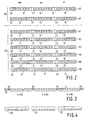
- Fig. 2 shows a suitable format for carrier information as this information is recorded as successive bits in the auxiliary signal in the pregroove portion in an embodiment of the information carrier according to the invention.
- a 24-bit-long unit is used, subdivided into 3 bytes.
- the carrier information includes, for example, address codes AC and auxiliary codes HC, which address codes AC indicate the position of a read part of the track 9 relative to the beginning of the track in minutes mm in bit positions 13, seconds ss in bit positions 14 and frames ff in bit positions 15, as is customary in the CD system.
- This Absolute Time Indication In the Pregroove is expressed in the Binary Coded Decimal (BCD) system.
- the auxiliary codes HC are distinguished from the address codes AC by specific values in designated bit positions 20, 21 and 22 which form the Most Significant Bits (MSB) of the time codes.
- the address codes AC 66, 67 contain 000, 100 respectively, in these three MSBs; the auxiliary codes HC 61, 62, 63, 64, 65 and 66 have the remaining values 010, 110, 001, 011, 111 and 101.
- the velocity-related information may be provided differently on the information carrier, for example, in the form of a bar code which is provided on the information carrier at a given location and can be read by a recording device.
- Fig. 3 diagrammatically shows a part of the track 9 in which the carrier information is coded.
- the auxiliary signal contains, in essence, address codes AC and an auxiliary code HC in one in ten possible codes.
- the auxiliary codes HC comprise recording information that relates to the information carrier 1 such as, for example, possible beginnings and ends of the Lead-In and lead-Out areas, or recording parameters of the recording process, such as the necessary write power of the radiation beam.
- several bits in a specific auxiliary code HC are used for denoting a reference velocity, whereas the other recording parameters are fixed. As a result, it is possible to optimize an information carrier at a velocity, for example, double velocity that deviates from the customary standard velocity.
- the second embodiment has a range of recording velocities in which the recording parameters can be used and for which the information carrier is suitable.
- the range of velocities may be denoted by both a minimum and a maximum velocity, but it is also possible that only a minimum or maximum velocity is given.
- the actual recording velocity is to lie in the range. If the nominal recording velocity is deviated from, a correction may be applied to the recording parameters, as required.
- the recording parameters are given for a first recording velocity
- further recording parameters are given which are calculated at least at a further recording velocity that deviates from the first recording velocity.
- one of the recording velocities may be used for which parameters are available on the disc.
- correction parameters which are indicative of a deviation from the recording parameters at a second recording velocity are included.
- a correction may be calculated for the recording parameters in dependence on a difference between the first recording velocity and a recording velocity used.
- the process information is included. This process information denotes that at certain recording velocities that deviate from the first recording velocity, a different recording process is to be used. In this respect, there may be indicated, for example, that a preheating pulse or an entirely different series of pulses is to be applied at a certain deviating recording velocity.
- auxiliary codes on the information carrier several times with, for example, different reference velocities, different recording parameters and possibly different recording processes may be indicated at different reference velocities or, for example, different wavelengths of the recording radiation source.
- Fig. 4 shows an example of recording information with velocity-related information. It has the format of an auxiliary code described with reference to Fig. 2, in which code 101, in MSB positions 20, 21, 22, denotes that the remaining bits of the respective auxiliary code HC contain velocity-related information according to an agreed format.
- the bits S1-S3 and A1-A3 may be used to denote a sub-type while a different recording process may be established, as required, for each sub-type.
- the type of disc and sub-type may also be used for adapting the format in which the remaining parameters are transferred. For example, a CD-WO will require a different recording process with different recording parameters from a CD-E.
- the meaning of the various bits in the auxiliary codes may thus be rendered dependent on the type/sub-type of disc indicated. Even within the CD-E it is possible that different physical embodiments and choices of material are used for which different recording processes are necessary. The respective processes may also depend on the recording velocity.
- Fig. 5 shows a device for recording a disc-shaped information carrier 1.
- the device comprises coding means 52 and a read/write unit 57 for recording the information carrier 1 in accordance with a recording process.
- Information is applied to input 51 and converted in coding means 52 into a recording signal.
- the recording signal is coupled to the read/write unit 57.
- the information carrier 1 rotates, driven by drive means 58.
- the read/write unit 57 meanwhile scans track 9 via beam 56 and records patterns of indicia that represent information in the track.
- the read/write unit 57 is positioned over the track 9 by a servo system of a customary type (not shown).
- the system controller 59 checks the scanning of the information carrier 1 via drive means 58 and the servo system.
- the system controller 59 likewise controls the recording process via the coding means 52 and the read/write unit 57.
- a device will also comprise decoding means 53 for recovering the information from the patterns which are read out by the read/write unit 57. The recovered information is then produced on the output 54.
- the device further includes demodulator means 55 for recovering the recorded information.
- the servo signals generated during the following of the track are applied to demodulator means 55 which are arranged for demodulating the servo signals for the recovery of the auxiliary signal.
- the demodulator means 55 convert the address codes and the auxiliary codes from the auxiliary signal, which codes are transferred to the system controller 59.
- the recording parameters of the recording process are adapted by the system controller 59 in accordance with an adaptation procedure (see Fig. 6) as a function of the recording velocity and the recovered recorded information, among which velocity-related information.
- the write power used can be set in read/write unit 57 and the shape of the recorded signal can be set in coding means 52.
- Fig. 6 gives a diagrammatic representation of an adaptation procedure as carried out in the following steps by the system controller 59:
- S3 is executed as follows. The difference between the reference velocity and the actual recording velocity is given. If these velocities are the same, the read recording parameters are suitable at once and S4 follows. In the case of a difference, the recording parameters may be corrected by a fixed value if this correction value for the respective type of information carrier is known. It is also possible to adapt the recording velocity.
- S3 is executed as follows.
- One of the given velocities is selected, that is, the velocity that deviates the least from the desired recording velocity.
- the attendant recording parameters and an actual recording velocity are set and S4 follows.
- S3 is executed as follows. If the desired recording velocity lies within the range, S4 may follow at once. If not, the actual velocity is to be selected to lie within the range. In many cases the maximum possible velocity will be desired, and will be simply obtained in this manner. If the information carrier is of the type for which different velocity ranges with different attendant recording parameters are available, the velocity-related information is naturally to be read for such a period of time that all available velocity limits are found. Subsequently, a selection may be made for the range in which the desired recording velocity lies.
- S3 is executed as follows.
- the difference between the first recording velocity and the recording velocity to be used is determined.
- the correction parameters are then applied to the recording parameters in proportion to the velocity difference between the second recording velocity and the actual recording velocity. For example, if a correction parameter is given for four times as high a velocity, and the device can only cope with a velocity that is twice as high, the correction will have to be halved.
- S3 is executed as follows. If the desired recording velocity corresponds to a deviating velocity, for which a different recording process is given, the respective recording process is selected. If necessary, in the second instance there may still be a correction of the recording parameters of the selected process in one of the manners described above.
Abstract
Description
Claims (9)
- Information carrier of an inscribable type containing recording information indicative of a recording process by which information can be recorded on the information carrier, the recording information comprising recording parameters of the recording process, characterized in that the recording information comprises velocity-related information which is indicative of a recording velocity dependence of the recording process, the velocity-related information comprising a range of recording velocities in which the recording parameters can be used and for which the information carrier is suitable.
- Information carrier as claimed in Claim 1, characterized in that the velocity-related information comprises a maximum recording velocity.
- Information carrier as claimed in Claim 1 or 2, characterized in that the velocity-related information comprises a minimum recording velocity.
- Information carrier as claimed in Claim 1, characterized in that the recording parameters are given at a first recording velocity and in that the velocity-related information comprises correction parameters indicative of a deviation of the recording parameters at a second recording velocity for correcting the recording parameters in dependence on a difference between the first recording velocity and a recording velocity used.
- Information carrier as claimed in Claim 1 or 4, characterized in that the recording process is determined at a first recording velocity and in that the velocity-related information comprises process information indicative of at least a further recording process at a recording velocity that deviates from the first recording velocity.
- Device for recording an information carrier of an inscribable type as claimed in any one of Claims 1,2,4 and 5, the device comprising reading means for reading the recording information and recording means for recording the information carrier in accordance with an actual recording process, characterized in that the recording information comprises velocity-related information indicative of a recording velocity dependence of the recording process, which velocity-related information comprises a range of recording velocities in which the recording parameters can be used and for which the information carrier is suitable, and in that the recording means are arranged for controlling the actual recording process in dependence on an actual recording velocity and the velocity-related information and for selecting an actual recording velocity in dependence on the range of recording velocities.
- Device as claimed in Claim 6, characterized in that the recording means are adapted for selecting the maximum recording velocity to be the actual recording velocity.
- Device as claimed in Claim 6, characterized in that the recording means are adapted for controlling the recording process in dependence on the correction parameters and an actual recording velocity.
- Device as claimed in Claim 6 or 8, characterized in that the recording means are adapted for selecting an actual recording process in dependence on the process information and an actual recording velocity.
Applications Claiming Priority (3)
| Application Number | Priority Date | Filing Date | Title |
|---|---|---|---|
| BE9500809A BE1009677A3 (en) | 1995-09-29 | 1995-09-29 | INFORMATION CARRIER AND DEVICE FOR DESCRIBING AN INFORMATION CARRIER. |
| BE9500809 | 1995-09-29 | ||
| PCT/IB1996/000980 WO1997013244A1 (en) | 1995-09-29 | 1996-09-24 | Information carrier and recording device for recording an information carrier |
Publications (2)
| Publication Number | Publication Date |
|---|---|
| EP0852796A1 EP0852796A1 (en) | 1998-07-15 |
| EP0852796B1 true EP0852796B1 (en) | 1999-09-08 |
Family
ID=3889207
Family Applications (1)
| Application Number | Title | Priority Date | Filing Date |
|---|---|---|---|
| EP96929488A Expired - Lifetime EP0852796B1 (en) | 1995-09-29 | 1996-09-24 | Information carrier and recording device for recording an information carrier |
Country Status (17)
| Country | Link |
|---|---|
| US (1) | US5835462A (en) |
| EP (1) | EP0852796B1 (en) |
| JP (2) | JP4063321B2 (en) |
| KR (1) | KR100470007B1 (en) |
| CN (2) | CN1149543C (en) |
| AT (1) | ATE184416T1 (en) |
| BE (1) | BE1009677A3 (en) |
| CA (1) | CA2206297C (en) |
| CZ (1) | CZ291074B6 (en) |
| DE (1) | DE69604189T2 (en) |
| ES (1) | ES2138831T3 (en) |
| GR (1) | GR3031923T3 (en) |
| HK (1) | HK1012520A1 (en) |
| ID (1) | ID16343A (en) |
| MY (1) | MY120906A (en) |
| TW (1) | TW397974B (en) |
| WO (1) | WO1997013244A1 (en) |
Families Citing this family (75)
| Publication number | Priority date | Publication date | Assignee | Title |
|---|---|---|---|---|
| JP3442243B2 (en) * | 1996-07-12 | 2003-09-02 | ティアック株式会社 | Data reproduction method and apparatus |
| JP3743178B2 (en) * | 1998-10-05 | 2006-02-08 | ヤマハ株式会社 | Recordable optical disc and optical disc recording apparatus |
| US6275458B1 (en) * | 1999-02-18 | 2001-08-14 | Terrence L. Wong | Method and apparatus for reading and writing a multi-level signal from an optical disc |
| US6580683B1 (en) | 1999-06-23 | 2003-06-17 | Dataplay, Inc. | Optical recording medium having a master data area and a writeable data area |
| DE60125993T2 (en) * | 2000-09-28 | 2007-10-18 | Ricoh Co., Ltd. | Optical recording medium, method for its production and method and apparatus for recording on or reading from this medium |
| ES2259312T3 (en) * | 2000-12-11 | 2006-10-01 | Koninklijke Philips Electronics N.V. | OPTICAL TYPE RECORDING SUPPORT AND A RECORDING AND / OR PLAYBACK DEVICE FOR USE WITH THIS RECORDING SUPPORT. |
| BRPI0108205B1 (en) * | 2000-12-11 | 2015-04-14 | Konink Philips Eletronics N V | Optically enrollable disk type record holder, and device for recording and / or reproducing an enrollable type record holder |
| US6728182B2 (en) | 2001-01-25 | 2004-04-27 | Dphi Acquisitions, Inc. | Tracking and focus servo system with a media type boundary crossing detector |
| US6956797B2 (en) * | 2001-01-25 | 2005-10-18 | Dphi Acquisitions, Inc. | Digital servo system with error signal integrity testing |
| US7680004B2 (en) * | 2001-01-25 | 2010-03-16 | Dphi Acquisitions, Inc. | Digital servo system with inverse non-linearity compensation |
| US6937543B2 (en) | 2001-01-25 | 2005-08-30 | Dphi Acquisitions, Inc. | Digital focus servo system with a sliding notch filter |
| US7492675B2 (en) * | 2001-01-25 | 2009-02-17 | Dphi Acquisitions, Inc. | Digital servo system with calibrated notch filters |
| US6809995B2 (en) | 2001-01-25 | 2004-10-26 | Dphi Acquisitions, Inc. | Digital focus and tracking servo system |
| US7020054B2 (en) * | 2001-01-25 | 2006-03-28 | Dphi Acquisitions, Inc. | Digital servo system with biased feed-forward |
| US6738320B2 (en) | 2001-01-25 | 2004-05-18 | Dphi Acquisitions, Inc. | System and method for moving optical pick up from current position to target position with smooth control |
| US7016280B2 (en) * | 2001-01-25 | 2006-03-21 | Dphi Acquisitions, Inc. | Tracking and focus servo system with defect detection |
| US6781929B2 (en) | 2001-01-25 | 2004-08-24 | Dphi Acquisitions, Inc. | Digital tracking servo system with multi-track seek |
| US6847596B2 (en) | 2001-01-25 | 2005-01-25 | Dphi Acquisitions, Inc. | Tracking servo system including a multi-track seek algorithm with a track zero crossing period integrity test |
| US7522480B2 (en) | 2001-01-25 | 2009-04-21 | Dphi Acquisitions, Inc. | Digital tracking servo system with multi-track seek with an acceleration clamp |
| US7023776B2 (en) * | 2001-01-25 | 2006-04-04 | Dphi Acquisitions, Inc. | Calibration initiation methods for a tracking and focus servo system |
| US6813226B2 (en) | 2001-01-25 | 2004-11-02 | Dphi Acquisitions, Inc. | Calibration of a focus sum threshold in a focus servo system |
| US6891789B2 (en) * | 2001-01-25 | 2005-05-10 | Dphi Acquisitions, Inc. | Tracking and focus servo system with automatic media type detector |
| US6704261B2 (en) | 2001-01-25 | 2004-03-09 | Dphi Acquisitions, Inc. | Spin motor control in an optical drive |
| US7095683B2 (en) * | 2001-01-25 | 2006-08-22 | Dphi Acquisitions, Inc. | Tracking and focus digital servo system with write abort |
| US6891781B2 (en) * | 2001-01-25 | 2005-05-10 | Dphi Acquisitions, Inc. | Digital servo system with second order compensator |
| US7593300B2 (en) | 2001-01-25 | 2009-09-22 | Dphi Acquisitions, Inc. | Digital tracking servo system with off-format detection |
| US6970403B2 (en) * | 2001-01-25 | 2005-11-29 | Dphi Acquisition, Inc. | Calibration of tracking error signal offset in a tracking servo system |
| US6882603B2 (en) * | 2001-01-25 | 2005-04-19 | Dphi Acquisitions, Inc. | Digital tracking servo system with tracking skate detection |
| US7414940B2 (en) | 2001-01-25 | 2008-08-19 | Dphi Acquisitions, Inc. | Calibration of a focus error signal gain in a focus servo system |
| US7782721B2 (en) * | 2001-01-25 | 2010-08-24 | Dphi Acquisitions, Inc. | Digital focus and tracking servo system with multi-zone calibration |
| US6906985B2 (en) | 2001-01-25 | 2005-06-14 | Dphi Acquisitions, Inc. | Calibration of tracking error signal gain in a tracking servo system |
| US6762980B2 (en) | 2001-01-25 | 2004-07-13 | Dphi Acquisitions, Inc. | Digital tracking servo system with a multi-track seeking and accelerated servo function for regaining a closed tracking loop |
| US6930963B2 (en) | 2001-01-25 | 2005-08-16 | Dphi Acquistions, Inc. | Tracking and focus servo system with head load |
| US7023766B2 (en) | 2001-01-25 | 2006-04-04 | Dphi Acquisitions, Inc. | Flexible servicing of servo algorithms using a digital signal processor |
| US6950380B2 (en) * | 2001-01-25 | 2005-09-27 | Dphi Acquisitions, Inc. | Detector input dark current offset calibration in an optical disk drive digital servo |
| US6882601B2 (en) | 2001-01-25 | 2005-04-19 | Dphi Acquisitions, Inc. | Digital servo system with feed-forward control loops |
| US6965547B2 (en) * | 2001-01-25 | 2005-11-15 | Dphi Acquisitions, Inc. | Tracking and focus servo system with error signal inverse non-linearity calibration |
| US6904007B2 (en) * | 2001-01-25 | 2005-06-07 | Dphi Acquisitions, Inc. | Digital servo system with loop gain calibration |
| US7260031B2 (en) | 2001-01-25 | 2007-08-21 | Dphi Acquisitions, Inc. | Digital focus and tracking servo system with one-track jump |
| US6958957B2 (en) * | 2001-01-25 | 2005-10-25 | Dphi Acquisitions, Inc. | Digital tracking and focus servo system with TES to FES crosstalk calibration |
| US6813228B2 (en) | 2001-01-25 | 2004-11-02 | Dphi Acquisitions, Inc. | Tracking and focus servo system with direction sensor |
| US6847597B2 (en) | 2001-01-25 | 2005-01-25 | Dphi Acquisitions, Inc. | Optical disk drive with a digital focus and tracking servo system |
| US6909676B2 (en) | 2001-01-25 | 2005-06-21 | Dphi Acquisitions, Inc. | Digital tracking servo system with multi-track seek with track zero crossing detection |
| US6922380B2 (en) | 2001-01-25 | 2005-07-26 | Dphi Acquisitions, Inc. | Tracking and focus servo system with anti-skate algorithm |
| US6970410B2 (en) * | 2001-01-25 | 2005-11-29 | Dphi Acquisitions, Inc. | Focus detection in a digital focus servo system |
| US7092322B2 (en) * | 2001-01-25 | 2006-08-15 | Dphi Acquisitions, Inc. | Calibration of focus error signal offset in a focus servo system |
| US6885619B2 (en) | 2001-01-25 | 2005-04-26 | Dphi Acquisitions, Inc. | Detector input stray light offset calibration in an optical disk drive |
| US7196979B2 (en) | 2001-01-25 | 2007-03-27 | Dphi Acquisitions, Inc. | Calibration storage methods for a digital focus and tracking servo system with calibration |
| US7672199B2 (en) | 2001-01-25 | 2010-03-02 | Dphi Acquisitions, Inc. | Close focus algorithm in a digital focus servo system |
| US6898164B2 (en) * | 2001-01-25 | 2005-05-24 | Dphi Acquisitions, Inc. | Close tracking algorithm in a digital tracking servo system |
| JP2002245625A (en) * | 2001-02-19 | 2002-08-30 | Pioneer Electronic Corp | Recording medium, information recording device and method, information recording medium and recording program |
| KR100567515B1 (en) | 2001-04-27 | 2006-04-03 | 마쯔시다덴기산교 가부시키가이샤 | Recordable optical disc, optical disc recording apparatus, optical disc reproduction apparatus, and method for recording data onto recordable optical disc |
| JP2003045036A (en) | 2001-07-27 | 2003-02-14 | Toshiba Corp | Optical disk, optical disk recording playback device and optical disk recording playback method |
| JP2003203341A (en) | 2001-11-02 | 2003-07-18 | Victor Co Of Japan Ltd | Optical disk, optical disk recording and playing back device, and optical disk recording and playing back method |
| EP1485915A2 (en) * | 2001-12-21 | 2004-12-15 | Koninklijke Philips Electronics N.V. | Record carrier and scanning device |
| TWI257624B (en) | 2002-02-01 | 2006-07-01 | Matsushita Electric Ind Co Ltd | Information medium and information recording/reproduction apparatus |
| EP1497826A4 (en) * | 2002-04-24 | 2008-08-27 | Samsung Electronics Co Ltd | Optical information storage medium and method of recording thereon |
| KR20030092588A (en) * | 2002-05-30 | 2003-12-06 | 삼성전자주식회사 | Optical information storage medium and method of recording/reproducing in the same |
| JP2004046966A (en) * | 2002-07-11 | 2004-02-12 | Ricoh Co Ltd | Optical information recording medium, recording condition deciding method, optical information recording device and information processor |
| EP1573721A1 (en) * | 2002-12-13 | 2005-09-14 | Koninklijke Philips Electronics N.V. | Record carrier comprising multiple sets of recording parameters |
| KR100750109B1 (en) * | 2003-02-15 | 2007-08-21 | 삼성전자주식회사 | Information storage medium |
| ATE411601T1 (en) * | 2003-03-11 | 2008-10-15 | Koninkl Philips Electronics Nv | RECORDING DEVICE FOR A TWO-SPEED OPTICAL RECORDING MEDIUM |
| KR100976472B1 (en) * | 2003-07-07 | 2010-08-18 | 엘지전자 주식회사 | Optical disc and recording method of Disc Information of optical disc |
| CA2472364C (en) * | 2003-07-07 | 2012-07-17 | Lg Electronics Inc. | A recording medium, method of configuring control information thereof, method for recording or reproducing data using the same, and apparatus thereof |
| KR100953637B1 (en) * | 2003-07-07 | 2010-04-20 | 엘지전자 주식회사 | Optical disc and recording method of Disc Information of optical disc |
| CA2474995C (en) * | 2003-07-07 | 2011-11-22 | Lg Electronics Inc. | Recording medium, method of configuring control information thereof, recording and/or reproducing method using the same, and apparatus thereof |
| US7564760B2 (en) * | 2003-07-09 | 2009-07-21 | Lg Electronics, Inc. | Recording medium, method of configuring disc control information thereof, recording and reproducing method using the same, and apparatus thereof |
| EP1649456A2 (en) * | 2003-07-21 | 2006-04-26 | Koninklijke Philips Electronics N.V. | Method and apparatus for determining the optimal write power, and optical recording medium for use by such method and apparatus |
| KR101024904B1 (en) * | 2003-08-14 | 2011-03-31 | 엘지전자 주식회사 | Recording medium,recording method, recording apparatus and recording/reproducing system |
| ATE462180T1 (en) * | 2003-08-14 | 2010-04-15 | Lg Electronics Inc | RECORDING MEDIUM, CONFIGURATION METHOD FOR THE RELATED TAX INFORMATION, RECORDING AND PLAYBACK METHOD AND APPARATUS THEREOF |
| AU2003303081B8 (en) | 2003-08-14 | 2009-02-26 | Lg Electronics Inc. | Recording medium, method of configuring control information thereof, recording and/or reproducing method using the same, and apparatus thereof |
| JP2007502496A (en) * | 2003-08-14 | 2007-02-08 | エルジー エレクトロニクス インコーポレーテッド | RECORDING MEDIUM, RECORDING MEDIUM CONTROL INFORMATION CONFIGURATION METHOD, RECORDING / REPRODUCING METHOD USING THE SAME, AND DEVICE |
| JP2005166111A (en) * | 2003-11-28 | 2005-06-23 | Pioneer Electronic Corp | Recording medium, apparatus, method and program for information recording, and information recording medium |
| EP2287846B1 (en) | 2004-05-13 | 2015-07-01 | LG Electronics Inc. | Recording medium, read/write method thereof and read/write apparatus thereof |
| KR101041809B1 (en) * | 2004-07-27 | 2011-06-17 | 엘지전자 주식회사 | Optical disc and configuring disc control information and recording/reproducing method using the same and apparatus thereof |
Citations (1)
| Publication number | Priority date | Publication date | Assignee | Title |
|---|---|---|---|---|
| US5457674A (en) * | 1990-09-04 | 1995-10-10 | Mitsubishi Denki Kabushiki Kaisha | Optical disc recording apparatus |
Family Cites Families (15)
| Publication number | Priority date | Publication date | Assignee | Title |
|---|---|---|---|---|
| FR2546325B1 (en) * | 1983-05-20 | 1988-07-08 | Thomson Csf | OPTICAL POWER CALIBRATION METHOD AND DEVICE APPLIED TO AN OPTICAL DISC FOR DATA RECORDING |
| JP2609593B2 (en) * | 1986-10-24 | 1997-05-14 | 株式会社日立製作所 | Disk medium recording method and disk device |
| JPS63205819A (en) * | 1987-02-20 | 1988-08-25 | Pioneer Electronic Corp | Optical information recorder |
| US5418764A (en) * | 1988-01-22 | 1995-05-23 | U.S. Philips Corporation | Recording device, a record carrier having preformatted address codes and auxiliary codes providing control data for use by the recording device, and an information recording system including both the recording device and the record carrier |
| US5187699A (en) * | 1988-01-22 | 1993-02-16 | U.S. Philips Corporation | Method and apparatus for successively recording two EFM-modulated signals enabling detection of boundary condition for transitioning between signals |
| NL8800151A (en) * | 1988-01-22 | 1989-08-16 | Philips Nv | METHOD AND APPARATUS FOR RECORDING AN INFORMATION SIGNAL |
| ES2080783T4 (en) * | 1989-05-08 | 2005-06-16 | Koninklijke Philips Electronics N.V. | SYSTEM FOR RECORDING INFORMATION, AND RECORDING DEVICE AND RECORDING SUPPORT FOR USE IN A SYSTEM FOR RECORDING INFORMATION OF THIS TYPE. |
| NL8901491A (en) * | 1989-06-13 | 1991-01-02 | Philips Nv | Recording audio signals on compact disc - combining digitised signal input with data relevant to recording speed and other characteristics |
| JPH03201266A (en) * | 1989-12-27 | 1991-09-03 | Victor Co Of Japan Ltd | Draw type information recording medium and its recording device |
| NL9000150A (en) * | 1990-01-22 | 1991-08-16 | Philips Nv | METHOD AND APPARATUS FOR APPLYING A PATTERN OF AREAS WITH CHANGED OPTICAL PROPERTIES IN A RECORD CARRIER |
| NL9000327A (en) * | 1990-02-12 | 1991-09-02 | Philips Nv | INFORMATION RECORDING DEVICE. |
| JP3039099B2 (en) * | 1992-02-14 | 2000-05-08 | ソニー株式会社 | Optical disk recording apparatus and method |
| JP2605577B2 (en) * | 1993-03-19 | 1997-04-30 | ヤマハ株式会社 | Optical disk recording device |
| JPH0773471A (en) * | 1993-09-03 | 1995-03-17 | Pioneer Electron Corp | Information recorder for draw type optical disk |
| JPH0773470A (en) * | 1993-09-03 | 1995-03-17 | Pioneer Electron Corp | Draw type optical disk and its recorder |
-
1995
- 1995-09-29 BE BE9500809A patent/BE1009677A3/en not_active IP Right Cessation
-
1996
- 1996-09-24 WO PCT/IB1996/000980 patent/WO1997013244A1/en active IP Right Grant
- 1996-09-24 DE DE69604189T patent/DE69604189T2/en not_active Expired - Lifetime
- 1996-09-24 JP JP51409797A patent/JP4063321B2/en not_active Expired - Lifetime
- 1996-09-24 CA CA2206297A patent/CA2206297C/en not_active Expired - Lifetime
- 1996-09-24 CZ CZ19971610A patent/CZ291074B6/en not_active IP Right Cessation
- 1996-09-24 ES ES96929488T patent/ES2138831T3/en not_active Expired - Lifetime
- 1996-09-24 EP EP96929488A patent/EP0852796B1/en not_active Expired - Lifetime
- 1996-09-24 KR KR1019970703582A patent/KR100470007B1/en not_active IP Right Cessation
- 1996-09-24 AT AT96929488T patent/ATE184416T1/en active
- 1996-09-24 CN CNB961915323A patent/CN1149543C/en not_active Expired - Lifetime
- 1996-09-24 CN CNB031457533A patent/CN100517473C/en not_active Expired - Lifetime
- 1996-09-27 MY MYPI96004010A patent/MY120906A/en unknown
- 1996-09-30 ID IDP962786A patent/ID16343A/en unknown
- 1996-09-30 US US08/722,651 patent/US5835462A/en not_active Expired - Lifetime
- 1996-12-10 TW TW085115279A patent/TW397974B/en not_active IP Right Cessation
-
1998
- 1998-12-21 HK HK98114109A patent/HK1012520A1/en not_active IP Right Cessation
-
1999
- 1999-11-23 GR GR990403014T patent/GR3031923T3/en unknown
-
2007
- 2007-08-08 JP JP2007206881A patent/JP2007335077A/en active Pending
Patent Citations (1)
| Publication number | Priority date | Publication date | Assignee | Title |
|---|---|---|---|---|
| US5457674A (en) * | 1990-09-04 | 1995-10-10 | Mitsubishi Denki Kabushiki Kaisha | Optical disc recording apparatus |
Also Published As
| Publication number | Publication date |
|---|---|
| ES2138831T3 (en) | 2000-01-16 |
| CZ291074B6 (en) | 2002-12-11 |
| DE69604189T2 (en) | 2000-04-13 |
| DE69604189D1 (en) | 1999-10-14 |
| EP0852796A1 (en) | 1998-07-15 |
| CN1182497A (en) | 1998-05-20 |
| JP2007335077A (en) | 2007-12-27 |
| KR980700646A (en) | 1998-03-30 |
| MX9703953A (en) | 1997-09-30 |
| MY120906A (en) | 2005-12-30 |
| TW397974B (en) | 2000-07-11 |
| CZ161097A3 (en) | 1999-04-14 |
| ID16343A (en) | 1997-09-25 |
| GR3031923T3 (en) | 2000-03-31 |
| JPH11513521A (en) | 1999-11-16 |
| WO1997013244A1 (en) | 1997-04-10 |
| CN1149543C (en) | 2004-05-12 |
| BE1009677A3 (en) | 1997-06-03 |
| CA2206297C (en) | 2011-08-09 |
| CA2206297A1 (en) | 1997-04-10 |
| ATE184416T1 (en) | 1999-09-15 |
| KR100470007B1 (en) | 2005-04-06 |
| US5835462A (en) | 1998-11-10 |
| JP4063321B2 (en) | 2008-03-19 |
| CN100517473C (en) | 2009-07-22 |
| CN1475991A (en) | 2004-02-18 |
| HK1012520A1 (en) | 1999-08-06 |
Similar Documents
| Publication | Publication Date | Title |
|---|---|---|
| EP0852796B1 (en) | Information carrier and recording device for recording an information carrier | |
| US6298021B2 (en) | Optical disc and optical disc apparatus for forming wobbled tracks | |
| US4789975A (en) | Apparatus for recording and/or reproducing data signal on or from disk shaped recording medium at a variably selected constant linear velocity | |
| KR100236888B1 (en) | Information recording system, and recording device and record carrier for use in such an information recording system | |
| US5629912A (en) | Focusing servo controlling apparatus | |
| US5563862A (en) | Write once optical disc recording apparatus with reduced data error rate because the value of asymmetry is equalized as additional data is recorded thereon | |
| US5978350A (en) | Optical disc and optical disc driving device | |
| EP0411961B1 (en) | Optical disk recording/reproducing device | |
| EP0709837A2 (en) | Optical disks and recording/reproduction thereof | |
| US6996047B2 (en) | Optical disc recording method and apparatus | |
| EP1342235B1 (en) | Record carrier of the optical type and a device for recording and/or playback for use with such a record carrier | |
| EP0709842B1 (en) | Recording and reproduction of data | |
| US7355946B2 (en) | Method of recording signals onto a recording medium | |
| KR0136908B1 (en) | Optically readable record carrier of the inscribable type and optical read apparatus for reading such record carrier | |
| JP2783136B2 (en) | Optical disk recording device | |
| JPH08115523A (en) | Optical disk and optical disk driving device | |
| EP1356464B1 (en) | Record carrier of the optical type and a device for recording and/or playback for use with such a record carrier | |
| MXPA97003953A (en) | Carrier of information and registration device to register an information carrier | |
| JP2900657B2 (en) | Optical disk drive | |
| JPH08115571A (en) | Optical disk | |
| AU2244299A (en) | Optical disk and optical disk drive device | |
| JPH08203252A (en) | Method and apparatus for detecting address |
Legal Events
| Date | Code | Title | Description |
|---|---|---|---|
| PUAI | Public reference made under article 153(3) epc to a published international application that has entered the european phase |
Free format text: ORIGINAL CODE: 0009012 |
|
| 17P | Request for examination filed |
Effective date: 19980429 |
|
| AK | Designated contracting states |
Kind code of ref document: A1 Designated state(s): AT BE DE ES FR GB GR IT NL PT |
|
| GRAG | Despatch of communication of intention to grant |
Free format text: ORIGINAL CODE: EPIDOS AGRA |
|
| 17Q | First examination report despatched |
Effective date: 19981125 |
|
| GRAG | Despatch of communication of intention to grant |
Free format text: ORIGINAL CODE: EPIDOS AGRA |
|
| GRAH | Despatch of communication of intention to grant a patent |
Free format text: ORIGINAL CODE: EPIDOS IGRA |
|
| GRAH | Despatch of communication of intention to grant a patent |
Free format text: ORIGINAL CODE: EPIDOS IGRA |
|
| GRAA | (expected) grant |
Free format text: ORIGINAL CODE: 0009210 |
|
| AK | Designated contracting states |
Kind code of ref document: B1 Designated state(s): AT BE DE ES FR GB GR IT NL PT |
|
| REF | Corresponds to: |
Ref document number: 184416 Country of ref document: AT Date of ref document: 19990915 Kind code of ref document: T |
|
| REF | Corresponds to: |
Ref document number: 69604189 Country of ref document: DE Date of ref document: 19991014 |
|
| ITF | It: translation for a ep patent filed |
Owner name: ING. C. GREGORJ S.P.A. |
|
| ET | Fr: translation filed | ||
| REG | Reference to a national code |
Ref country code: ES Ref legal event code: FG2A Ref document number: 2138831 Country of ref document: ES Kind code of ref document: T3 |
|
| REG | Reference to a national code |
Ref country code: PT Ref legal event code: SC4A Free format text: AVAILABILITY OF NATIONAL TRANSLATION Effective date: 19991126 |
|
| PLBE | No opposition filed within time limit |
Free format text: ORIGINAL CODE: 0009261 |
|
| STAA | Information on the status of an ep patent application or granted ep patent |
Free format text: STATUS: NO OPPOSITION FILED WITHIN TIME LIMIT |
|
| 26N | No opposition filed | ||
| REG | Reference to a national code |
Ref country code: GB Ref legal event code: IF02 |
|
| REG | Reference to a national code |
Ref country code: DE Ref legal event code: R082 Ref document number: 69604189 Country of ref document: DE Representative=s name: EISENFUEHR, SPEISER & PARTNER, DE |
|
| REG | Reference to a national code |
Ref country code: DE Ref legal event code: R082 Ref document number: 69604189 Country of ref document: DE Representative=s name: EISENFUEHR SPEISER PATENTANWAELTE RECHTSANWAEL, DE Effective date: 20130614 Ref country code: DE Ref legal event code: R082 Ref document number: 69604189 Country of ref document: DE Representative=s name: EISENFUEHR, SPEISER & PARTNER, DE Effective date: 20130614 Ref country code: DE Ref legal event code: R081 Ref document number: 69604189 Country of ref document: DE Owner name: KONINKLIJKE PHILIPS N.V., NL Free format text: FORMER OWNER: KONINKLIJKE PHILIPS ELECTRONICS N.V., EINDHOVEN, NL Effective date: 20130614 |
|
| REG | Reference to a national code |
Ref country code: ES Ref legal event code: PC2A Owner name: KONINKLIJKE PHILIPS N.V. Effective date: 20140220 |
|
| REG | Reference to a national code |
Ref country code: FR Ref legal event code: CD Owner name: KONINKLIJKE PHILIPS ELECTRONICS N Effective date: 20141126 Ref country code: FR Ref legal event code: CA Effective date: 20141126 |
|
| REG | Reference to a national code |
Ref country code: FR Ref legal event code: PLFP Year of fee payment: 20 |
|
| PGFP | Annual fee paid to national office [announced via postgrant information from national office to epo] |
Ref country code: PT Payment date: 20150914 Year of fee payment: 20 Ref country code: DE Payment date: 20150911 Year of fee payment: 20 Ref country code: GB Payment date: 20150930 Year of fee payment: 20 |
|
| PGFP | Annual fee paid to national office [announced via postgrant information from national office to epo] |
Ref country code: GR Payment date: 20150925 Year of fee payment: 20 Ref country code: AT Payment date: 20150925 Year of fee payment: 20 |
|
| PGFP | Annual fee paid to national office [announced via postgrant information from national office to epo] |
Ref country code: IT Payment date: 20150925 Year of fee payment: 20 |
|
| PGFP | Annual fee paid to national office [announced via postgrant information from national office to epo] |
Ref country code: NL Payment date: 20150928 Year of fee payment: 20 Ref country code: FR Payment date: 20150930 Year of fee payment: 20 Ref country code: BE Payment date: 20150930 Year of fee payment: 20 Ref country code: ES Payment date: 20151027 Year of fee payment: 20 |
|
| REG | Reference to a national code |
Ref country code: DE Ref legal event code: R071 Ref document number: 69604189 Country of ref document: DE |
|
| REG | Reference to a national code |
Ref country code: NL Ref legal event code: MK Effective date: 20160923 |
|
| REG | Reference to a national code |
Ref country code: GB Ref legal event code: PE20 Expiry date: 20160923 |
|
| PG25 | Lapsed in a contracting state [announced via postgrant information from national office to epo] |
Ref country code: GB Free format text: LAPSE BECAUSE OF EXPIRATION OF PROTECTION Effective date: 20160923 |
|
| REG | Reference to a national code |
Ref country code: AT Ref legal event code: MK07 Ref document number: 184416 Country of ref document: AT Kind code of ref document: T Effective date: 20160924 |
|
| REG | Reference to a national code |
Ref country code: ES Ref legal event code: FD2A Effective date: 20170102 |
|
| REG | Reference to a national code |
Ref country code: GR Ref legal event code: MA Ref document number: 990403014 Country of ref document: GR Effective date: 20160925 |
|
| PG25 | Lapsed in a contracting state [announced via postgrant information from national office to epo] |
Ref country code: PT Free format text: LAPSE BECAUSE OF EXPIRATION OF PROTECTION Effective date: 20161004 Ref country code: ES Free format text: LAPSE BECAUSE OF EXPIRATION OF PROTECTION Effective date: 20160925 |