EP0854604A1 - Multicast group addressing - Google Patents
Multicast group addressing Download PDFInfo
- Publication number
- EP0854604A1 EP0854604A1 EP97480001A EP97480001A EP0854604A1 EP 0854604 A1 EP0854604 A1 EP 0854604A1 EP 97480001 A EP97480001 A EP 97480001A EP 97480001 A EP97480001 A EP 97480001A EP 0854604 A1 EP0854604 A1 EP 0854604A1
- Authority
- EP
- European Patent Office
- Prior art keywords
- node
- network
- datagram
- end users
- access
- Prior art date
- Legal status (The legal status is an assumption and is not a legal conclusion. Google has not performed a legal analysis and makes no representation as to the accuracy of the status listed.)
- Withdrawn
Links
Images


Classifications
-
- H—ELECTRICITY
- H04—ELECTRIC COMMUNICATION TECHNIQUE
- H04L—TRANSMISSION OF DIGITAL INFORMATION, e.g. TELEGRAPHIC COMMUNICATION
- H04L12/00—Data switching networks
- H04L12/02—Details
- H04L12/16—Arrangements for providing special services to substations
- H04L12/18—Arrangements for providing special services to substations for broadcast or conference, e.g. multicast
- H04L12/1863—Arrangements for providing special services to substations for broadcast or conference, e.g. multicast comprising mechanisms for improved reliability, e.g. status reports
- H04L12/1877—Measures taken prior to transmission
-
- H—ELECTRICITY
- H04—ELECTRIC COMMUNICATION TECHNIQUE
- H04L—TRANSMISSION OF DIGITAL INFORMATION, e.g. TELEGRAPHIC COMMUNICATION
- H04L12/00—Data switching networks
- H04L12/02—Details
- H04L12/16—Arrangements for providing special services to substations
- H04L12/18—Arrangements for providing special services to substations for broadcast or conference, e.g. multicast
- H04L12/1854—Arrangements for providing special services to substations for broadcast or conference, e.g. multicast with non-centralised forwarding system, e.g. chaincast
-
- H—ELECTRICITY
- H04—ELECTRIC COMMUNICATION TECHNIQUE
- H04L—TRANSMISSION OF DIGITAL INFORMATION, e.g. TELEGRAPHIC COMMUNICATION
- H04L12/00—Data switching networks
- H04L12/02—Details
- H04L12/16—Arrangements for providing special services to substations
- H04L12/18—Arrangements for providing special services to substations for broadcast or conference, e.g. multicast
- H04L12/1886—Arrangements for providing special services to substations for broadcast or conference, e.g. multicast with traffic restrictions for efficiency improvement, e.g. involving subnets or subdomains
Definitions
- the present invention relates to connectionless transmission in high speed packet switching networks, and in particular to a group addressing method and system for sending a datagram to one or a plurality of destination nodes and within these nodes for duplicating the datagram and to forward it to multiple end users.
- This vision of a high speed multi-protocol network is the driver for the emergence of fast packet switching network architectures in which data, voice, and video information is digitally encoded, chopped into small packets (of fixed or variable length) and transmitted through a common set of nodes and links.
- One of the key requirements of high speed packet switching networks is to reduce the end to end delay in order to satisfy real time delivery constraints and to achieve the necessary high nodal throughput for the transport of voice and video. Increases in link speeds have not been matched by proportionate increases in the processing speeds of communication nodes and the fundamental challenge for high speed networks is to minimize the processing time and to take full advantage of the high speed/low error rate technologies. Most of the transport and control functions provided by the new high bandwidth network architectures are performed on an end to end basis. The flow control and particularly the path selection and bandwidth management processes are managed by the access points of the network which reduces both the awareness and the functions of the intermediate nodes.
- Communication networks have at their disposal limited resources to ensure efficient packet transmissions.
- An efficient bandwidth management is essential to take full advantage of a high speed network. While transmission costs per byte continue to drop year after year, transmission costs are likely to continue to represent the major expense of operating future telecommunication networks as the demand for bandwidth increases. Thus considerable efforts have been spent on designing flow and congestion control processes, bandwidth reservation mechanisms, routing algorithms to manage the network bandwidth.
- An ideal network should be able to transmit an useful traffic directly proportional to the traffic offered to the network and this as far as the maximum transmission capacity is reached. Beyond this limit, the network should operate at its maximum capacity whatever the demand is.
- the nodes In high speed networks, the nodes must provide total connectivity. This includes attachment of the user devices, regardless of vendor or protocol, and the ability to have the end user communicate with any other device or group of devices (when justified or required).
- the network must support any type of traffic including data, voice, video, fax, graphic or image.
- Nodes must be able to take advantage of all common carrier facilities and to be adaptable to a plurality of protocols. All needed conversions must be automatic and transparent to the end user.
- Transport, Network Control and Access Services provide the capability to support communications between many different types of communicating devices through a common network infrastructure.
- Each Access Service also called Access Agent
- Each Access Service provides the support for a particular set of telecommunication services - ATM, Frame relay, PCM voice, Circuit emulation, HDLC ... - and enables those to transport traffic across a common network.
- An Access Agent comprises three logically separate components :
- Each network node contains one or many of these Access Agents, depending on the physical interfaces it attaches to and on the access protocols it understands and supports.
- Valid examples of access services are Frame Relay or Asynchronous Transfer Mode (ATM) Access Agents (for connection-oriented protocols) or Internet Protocol or Connection-Less Network Protocol Access Agents from the OSI suite (for connectionless protocols).
- ATM Asynchronous Transfer Mode
- One distinguishing characteristic of a network is the presence or absence of a "connection" between end users. When a connection is present the network is called “Connection-oriented” and when there is no connection the network is called “Connectionless”.
- the transfer of information between two communicating end users starts by the establishment of a connection prior to the real transfer of packets. Once the connection is established, there is no need to place a destination address in the packet header every time a packet is sent. All that is needed is an identifier to specify which connection is to be used for this packet.
- connection-oriented networks require the establishment of a network connection between the sending end user (sender) and the receiving end users (receivers) called point-to-multipoint connection.
- point-to-multipoint connection When the communication involves multiple sending end users to groups of receiving end users, a multipoint-to-multipoint connection or several point-to-multipoint connections must be set up.
- Packets also called datagrams in connectionless environments
- end users also called subscribers
- Network nodes do not keep any information relating to interactions currently in progress between end users of the network. Every datagram transmitted is prefixed by the full network address of both its origin and its destination.
- connection-less networks where :
- the present application relates to connectionless transmissions in wide-area networks based for example on the IBM's Networking BroadBand Services architecture described in the publication of International Business Machine "IBM International Technical Support Centers - Networking Broadband Services (NBBS) - Architecture tutorial - GG24-4486-00 June 95". More particularly, the present application relates to a set of mechanisms that connectionless Access Services can use to provide group addressing ("group addressing" is the terminology used for "multicasting" in the connectionless environment). These mechanisms are used in multi-node networks where each node can offer Access Services supporting connectionless protocols.
- Connection-less Protocol Agents exchange datagrams across the network, using the services provided by the generic Transport Services.
- a datagram is addressed to a group of several end users, generally attached to the network via different physical interfaces, the datagram is frequently sent to multiple destination nodes and processed by multiple Protocol Agents within said nodes before finally reaching all the end users of the group.
- the SMDS "Switched Multimegabit Data Services” (or the European equivalent CBDS “Connectionless Broadband Data Services”) architecture specifies that a copy of a group addressed datagram has to be delivered to every physical interface that attaches one or more end users belonging to the group of end users the datagram must be delivered to.
- the object of the present invention is to take advantage of a specific data transfer mode called "Remote Access to Functional Addressing" allowing the sending of a datagram to a destination node and within said node, the duplication of said datagram for a forwarding towards multiple destinations.
- a specific data transfer mode called "Remote Access to Functional Addressing”
- the claimed method and system reduce to a minimum, first, the overhead usually associated with multicast operations in connectionless services, and second, the required amount of manual resource definition as in a given node, only local end users of said node have to be manually defined (unless the connectionless protocol allows for' some form of automatic discovery of local resources).
- the present application relates to a method for addressing a datagram from an access source node to a group of end users in one or multiple access destination nodes in a connectionless communication network comprising a plurality of access and transit nodes interconnected with transmission links, access nodes attaching one or a plurality of end users, a group of end users comprising one or multiple sets of end users, each set of end users being attached to a destination node.
- Said method involves the steps of :
- Each access destination node attaching one or a plurality of sets of end users comprises intra node multicasting addressing means for, at reception of a datagram :
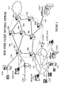
- Figure 1 a shows a typical network where a datagram is transmitted to a group of end users according to the present invention.
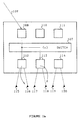
- Figure 1 b shows the handling of a multicasted datagram within a destination node according to the present invention.
- Figure 2 shows a typical model of a high speed packet switching network including the access and transit nodes.
- Figure 3 describes a high speed Routing Point.
- a typical model of communication system is made of several user networks (212) communicating through a high performance network (200) using private lines, carrier provided services, or public data networks.
- Each user network can be described as a set of communication processors and links (211) interconnecting large computers used as enterprise servers (213), user groups using workstations or personal computers attached on LAN (Local Area Networks 214), applications servers (215), PBX (Private Branch eXchange 216) or video servers (217).
- These user networks spread in different establishments, need to be interconnected through wide area transport facilities and different approaches can be used for organizing the data transfer.
- Some architectures involve the checking for data integrity at each network node, thus slowing down the transmission. Others are essentially looking for a high speed data transfer. To that end the transmission, routing and switching techniques within the nodes are optimized to process the flowing packets toward their final destination at the highest possible rate.
- the present invention belongs essentially to the latter category and more particularly to the fast packet switching network architecture detailed in the following paragraphs.
- the general view in Figure 2 shows a fast packet switching transmission system comprising eight nodes (201 to 208) each node being interconnected by means of high speed communication lines called Trunks (209).
- the access (210) to the high speed network by the users is realized through Access Nodes (202 to 205) located at the periphery.
- These Access Nodes comprise one or more Ports, each one providing an access point for attaching external devices supporting standard interfaces to the network and performing the conversions required to transport the users data flow across the network from and to other external devices.
- the Access Node (202) interfaces respectively a Private Branch eXchange (PBX), an application server and a hub through three Ports and communicates through the network by means of the adjacent Transit Nodes (201), (205) and (208).
- PBX Private Branch eXchange
- Each network node (201 to 208) includes a Routing Point where the incoming data packets are selectively routed on the outgoing Trunks towards the neighboring Transit Nodes. Such routing decisions are made according to the information contained in the header of the data packets.
- the network nodes provide ancillary services such as:
- Each Port is connected to a plurality of user processing equipment, each user equipment comprising either a source of digital data to be transmitted to another user system, or a data sink for consuming digital data received from another user system, or, typically, both.
- the interpretation of the users protocols, the translation of the users data into packets formatted appropriately for their transmission on the packet network (200) and the generation of a header to route these packets are executed by an Access Agent running in the Port. This header is made of Control, Routing and Redundancy Check Fields.
- FIG. 3 shows a general block diagram of a typical Routing Point (300) such as it can be found in the network nodes (201 to 208) illustrated in Figure 2.
- a Routing Point comprises a high speed packet Switch (302) onto which packets arriving at the Routing Point are entered. Such packets are received:
- the adapters (304, 301) determine which packets are to be routed by means of the Switch (302) towards a local user network (307) or towards a transmission link (303) leaving the node.
- the adapters (301 and 304) include queuing circuits for queuing packets prior to or subsequent to their launch on the Switch (302).
- the Route Controller (305) calculates the optimum paths through the network (200) so as to satisfy a given set of quality-of-services specified by the user and to minimize the amount of network resources used to complete the communication path. Then, it builds the header of the packets generated in the Routing Point.
- the optimization criterion includes the number of intermediates nodes, the characteristics of the connection request, the capabilities and the utilisation of the links (Trunks) in the path, the number of intermediate nodes...
- the optimum route is stored in a Routing Database (308) for further reuse.
- Network Topology Database (306) All the information necessary for the routing, about the nodes and transmission links connected to the nodes, are contained in a Network Topology Database (306). Under steady state condition, every Routing Point has the same view of the network. The network topology information is updated when new links are activated, new nodes added to the network, when links or nodes are dropped or when link loads change significantly. Such information is exchanged by means of control messages with all other Route Controllers to provide the up-to-date topological information needed for path selection (such database updates are carried on packets very similar to the data packets exchanged between end users of the network). The fact that the network topology is kept current in every node through continuous updates allows dynamic network reconfigurations without disrupting end users logical connections (sessions).
- the incoming transmission links to the packet Routing Point may comprise links from external devices in the local user networks (210) or links (Trunks) from adjacent network nodes (209).
- the Routing Point operates in the same manner to receive each data packet and forward it on to another Routing Point is dictated by the information in the packet header.
- the fast packet switching network operates to enable a communication between any two end user applications without dedicating any transmission or node facilities to that communication path except for the duration of a single packet. In this way, the utilisation of the communication facilities of the packet network is optimized to carry significantly more traffic than would be possible with dedicated transmission links for each communication path.
- the Network Control Services are those that control, allocate, and manage the resources of the physical network.
- Each Routing Point has a set of the foregoing functions in the Route Controller (305) and uses it to facilitate the communications (connection-oriented or connectionless) between users applications.
- the Network Control Services include in particular:
- Access Agents enable external devices or networks to use the network services transparently without a requirement to be aware of the internal network control services and protocols.
- Access Agents are located in the access nodes and in a preferred embodiment in the access link interfaces of the adapters (210) connected to external communication devices.
- the external behaviour of a particular Access Agent is primarily characterized by the Protocol Agent as it is responsible for participating in protocol exchanges with attached external devices and networks and mapping those protocols to the protocol used by the backbone network.
- the Protocol Agent uses the Directory Agent to locate the various resources with which it needs to communicate within the network.
- the Protocol Agent then uses the Connection Agent to establish and maintain network connections with other Access Agents.
- Protocol Agent The interactions between the Protocol Agent and external devices and networks are generally specific to the type of Access Agent. For example, the Protocol Agent in an HDLC Access Agent will behave quite differently to the Protocol Agent in an ATM Access Agent.
- the Directory Agent is responsible for the registration and localization of information relating to services provided by the Access Agent.
- the Directory Agent participates in the Directory Services Network Control Service which provides a distributed directory service throughout the network.
- the Directory Agent performs, in particular, three main functions :
- Locating a resource means determining the network address of the Access Agent representing the resource.
- Directory Agents rely on the use of a distributed database. Each Directory Agent maintains a local database of information about the external resources accessible through its Access Agent as well as information about remote resources it has cached. Each resource entry includes the following :
- the Directory search process begins with an external user, using its native protocol, attempting to communicate with another user.
- the Protocol Agent portion of the local Access Agent receives this request and uses its Directory Agent to find the destination resources using the external-form address.
- the Directory Agent initially examines its database (also called Local Directory Database) :
- the Directory Agent passes the result to the requesting Protocol Agent.
- the Connection Agent is responsible for the establishment and ongoing maintenance of network connections that are provided by the Network Connection Layer.
- the Protocol Agent uses the Connection Agent to set up, maintain and take down the various network connections that are required to support the services provided by the Access Agent.
- connectionless Directory Agent per node that offers connectionless support and within in each of these nodes, one Protocol Agent per physical interface linked to a connectionless end user (which generally leads to several Protocol Agents per node).
- Datagrams received from an end user attached to an access node are first processed by the Protocol Agent of said node.
- the connectionless Access Agents ultimate role is to relay datagrams between end users across the network. These datagrams are sent/received to/from equipment outside the network and contain a routing label that identifies the destination of the datagram.
- the routing label is a group address label (as opposed to an individual address label)
- the datagram is destined to a plurality or group of end users (as opposed to one and only one end user).
- the Protocol Agent in the access node determines, based on the destination group address specified in the datagram, two related pieces of information :
- a node Functional Address is an intra node group addressing or multicasting information. It is a special label used in a node to specify a plurality instead of a single destination.
- the switch of said node delivers a copy of the datagram being sent to all its corresponding destinations.
- a node component a Directory Agent or a Protocol Agent for example
- Marking a Functional Address means letting the node switch know that every daragram containing the Functional Address routing label has to be delivered to the marking entity.
- the network architecture must reserve a pool of Functional Addresses to be used for connectionless services. Such a Functional Address needs to be unique inside a node but does not need to be unique on a network wide basis.
- Functional Addresses can not only be used in a "Remote Access to Functional Address" data transfer mode from outside of the node but they can also be used inside the node to allow the internal multicasting of information to any combination of Access Agents within the node.
- a Functional Address may be implemented as a N-bits register where each of these bits corresponds to one adapter that attaches to the switch in a node. When a bit is set, the corresponding adapter is a member of the Functional Address.
- Functional Address x'00011001' means that adapters 1, 4 and 5 (adapters range from 1 to 8) are members of the Functional Address.
- the Remote Access to Functional Address transfer mode is a generic service that allows to send a datagram in a point-to-point fashion to a destination node, along with a Functional Address to be used in the destination node to forward the message to local destinations.
- the point-to-point part is obtained via a source routing routing label and is determined by the Path Selection algorithm.
- a point-to-point route must be computed to determine the associated point-to-point routing labels.
- the Functional Address is concatenated to the point-to-point routing labels thereby completing the transfer mode "Remote Access to Functional Address".
- the datagram can then be delivered to all the Protocol Agents that contain an end user belonging to the group within the destination node. For each destination node, the same process is repeated.
- connectionless Directory Agent triggers low-frequency periodic messages across the network to let its peers (other connectionless directory agents of the same type) know about each group address the node locally supports. These messages contain the Functional Addresses to use in order to reach all the Protocol Agents in the node that handle a end user member of the subject group.
- the Directory Agent obtains the list of locally supported group addresses from the Protocol Agents collocated in the node.
- the way Protocol Agents themselves obtain the list of group addresses they support is protocol dependent and is outside the scope of this application.
- Functional Addresses can be determined dynamically according to the list of Protocol Agents supporting the same group address. This is also outside the scope of the present application.
- the collected information consists in the complete list of all the group addresses supported by the connectionless bearer service network. For each of these group address, one Functional Address per destination node is kept (one per peer node supporting an end user member of the corresponding group). All of this information are then be readily available when a group addressed datagram has to be forwarded to its destination end users.
- a refresh interval with a product specific initial value, is defined as the amount of time a Directory Agent has to wait between the sending of two consecutive refresh messages.
- the value of the refresh interval is doubled each time a message is sent, as long as the result remains below a predefined value.
- a clock based mechanism may be added to minimize the risk of having several nodes at the same time sending a refresh message. For instance, each node can select randomly (within reasonable limits) the time interval between refresh messages.
- a destination node When a destination node receives a datagram sent across the network via a "Remote Access to Functional Address", the Functional Address part of the network routing label is exploited to locally deliver the datagram to the set of Protocol Agents in the node that own an interface leading to one end user member of the group. These Protocol Agents are the ones that previously marked to the switch the Functional Address contained in the received datagram. Delivery of the datagram to its destined end users terminates the node's processing of the datagram. When every node of the network involved in the processing of the datagram has done the same processing, the datagram has been successfully processed by the connectionless bearer services network.
- Figure 1 a) shows a network composed of six communication nodes (100 to 105) and Figure 1 b) shows the internal structure of node (101).
- a single copy of the datagram is sent along paths (a) and (b) to each destination nodes - respectively nodes (101) and (104) - handling an end user member of the group.
- the group the datagram is destined for is made up by end users (121), (116) and (118).
- the Functional Address part of the transfer mode is used by adapter (108) to perform a multicast operation (c) over the node switch (107).
- This multicast operation delivers the datagram to only those destination Protocol Agents in adapters (112) and (113) of the destination node that handle one or more end users belonging to the group.
- the datagram is sent to the end users (116) and (118) attached to node (101) and to the end user (121) attached to node (104).
- the claimed method has to be compared with the sending of the datagram to all the connectionless Protocol Agents in every destination node as described in the background art section.
- the point-to-point portion of the data routing label brings the datagram to the destination node and the Functional Address part of the data routing label brings the datagram to each Protocol Agent that handles one or more end user members of the group the datagram is destined for.
- This mechanism removes the need for a centralized component in the destination nodes.
- Each connectionless Directory Agent distributes to its peers (the other connectionless Directory Agents in the network) the set of group addresses that it supports. Dynamic distribution of group addressing information minimizes the amount of manual definition required in the network. In effect, in the worst case, only node local resources have to be manually defined in the node that attaches them.
- the information associated with group addressing includes for each supported group address the Functional Address to be used in a node that supports it.
- the Functional Address specifies the combination of one or more Protocol Agents in a node owning a resource belonging to the group.
- Each of these group addresses is accompanied by the Functional Address that the node has allocated to the combination of the connectionless Protocol Agents involved in the processing of this group address.
- the node's Directory Agent caches the lists of group addresses and Functional Addresses from all peer connectionless nodes in the network. These lists are used to forward the datagrams destined to a group to their final destinations in the most efficient way.
Abstract
The present invention relates to connectionless transmission in high speed packet
switching networks, and in particular to a group addressing method and system for
sending a datagram to one or a plurality of destination nodes and within these
nodes for duplicating the datagram and to forward it to multiple end users. The
claimed invention takes advantage of a specific data transfer mode called "Remote
Access to Functional Addressing" allowing the sending of a datagram to a destination
node and within said node, the duplication of said datagram for a transmission
towards multiple destinations. By distributing, maintaining and using the required
addressing information corresponding to these multiple destinations within the
node, the claimed group addressing method and system reduce to a minimum, first,
the overhead usually associated with multicast operations in connectionless services,
and second, the required amount of manual resource definition as in a given
node, only local end users of said node have to be manually defined (unless the
connectionless protocol allows for some form of automatic discovery of local
resources).
Description
The present invention relates to connectionless transmission in high speed packet
switching networks, and in particular to a group addressing method and system for
sending a datagram to one or a plurality of destination nodes and within these
nodes for duplicating the datagram and to forward it to multiple end users.
Data transmission is now evolving with a specific focus on applications and by integrating
a fundamental shift in the customer traffic profile. Driven by the growth of
workstations, the local area networks interconnection, the distributed processing
between workstations and super computers, the new applications and the integration
of various and often conflicting structures - hierarchical versus peer to peer,
wide versus local area networks, voice versus data - the data profile has become
more bandwidth consuming, bursting, non-deterministic and requires more
connectivity. Based on the above, there is a strong requirement for supporting distributed
computing applications across high speed wide-area networks that can
carry local area network communications, voice, video and traffic among channel
attached hosts, business, engineering workstations, terminals, and small to intermediate
file servers. This vision of a high speed multi-protocol network is the driver for
the emergence of fast packet switching network architectures in which data, voice,
and video information is digitally encoded, chopped into small packets (of fixed or
variable length) and transmitted through a common set of nodes and links.
An efficient transport of mixed traffic streams on very high speed lines means for
these new network architectures a set of requirements in term of performance and
resource consumption which can be summarized as follows :
- a very high throughput and a very short packet processing time,
- an efficient flow and congestion control,
- a very large flexibility to support a wide range of connectivity options.
One of the key requirements of high speed packet switching networks is to reduce
the end to end delay in order to satisfy real time delivery constraints and to achieve
the necessary high nodal throughput for the transport of voice and video. Increases
in link speeds have not been matched by proportionate increases in the processing
speeds of communication nodes and the fundamental challenge for high speed networks
is to minimize the processing time and to take full advantage of the high
speed/low error rate technologies. Most of the transport and control functions provided
by the new high bandwidth network architectures are performed on an end to
end basis. The flow control and particularly the path selection and bandwidth management
processes are managed by the access points of the network which reduces
both the awareness and the functions of the intermediate nodes.
Communication networks have at their disposal limited resources to ensure efficient
packet transmissions. An efficient bandwidth management is essential to take
full advantage of a high speed network. While transmission costs per byte continue
to drop year after year, transmission costs are likely to continue to represent the
major expense of operating future telecommunication networks as the demand for
bandwidth increases. Thus considerable efforts have been spent on designing flow
and congestion control processes, bandwidth reservation mechanisms, routing
algorithms to manage the network bandwidth. An ideal network should be able to
transmit an useful traffic directly proportional to the traffic offered to the network
and this as far as the maximum transmission capacity is reached. Beyond this limit,
the network should operate at its maximum capacity whatever the demand is.
In high speed networks, the nodes must provide total connectivity. This includes
attachment of the user devices, regardless of vendor or protocol, and the ability to
have the end user communicate with any other device or group of devices (when
justified or required). The network must support any type of traffic including data,
voice, video, fax, graphic or image. Nodes must be able to take advantage of all
common carrier facilities and to be adaptable to a plurality of protocols. All needed
conversions must be automatic and transparent to the end user.
The architectures of most high speed packet switching networks specify a set of
generic services that offer end-to-end high bandwidth transport capabilities. Services
can be divided into three major areas :
- Transport Services :
- Transport Services provide a common infrastructure to support the transfer of packets across a network. They are not used directly but through Access Services. Transport Services can be divided in three distinct functions : a Logical Link Layer, a Network Connection Layer and Transport Protocols.
- Network Control Services
- Network Control Services ensure that the Transport and Access Services operate reliably, efficiently, and as automatically as possible. They are used to control, allocate, and manage the resources of a network on a real-time basis. They also provide network operators with the various facilities that are needed to configure, operate, and maintain a network on a day-to-day basis. This includes facilities for monitoring the performance of the network, accounting for its usage, and resolving problems.
- Access Services
- Access Services provide an interface between the common high speed network (or backbone network) and external devices or networks via access link interfaces. Access Services enable a wide range of external devices to get access to the common infrastructure provided by the Transport Services.
Together, the Transport, Network Control and Access Services provide the capability
to support communications between many different types of communicating
devices through a common network infrastructure.
A major capability of most high speed networks is their ability to support a diverse
range of high speed multimedia telecommunication services using common equipment.
Each Access Service (also called Access Agent) provides the support for a
particular set of telecommunication services - ATM, Frame relay, PCM voice, Circuit
emulation, HDLC ... - and enables those to transport traffic across a common
network.
An Access Agent comprises three logically separate components :
- a Protocol Agent which understands and interprets the access protocol (the connectionless protocol in the present application),
- a Directory Agent in charge of locating resources across the network, and
- a Connection Agent which establishes connections between Access Agents.
Each network node contains one or many of these Access Agents, depending on
the physical interfaces it attaches to and on the access protocols it understands and
supports. Valid examples of access services are Frame Relay or Asynchronous
Transfer Mode (ATM) Access Agents (for connection-oriented protocols) or Internet
Protocol or Connection-Less Network Protocol Access Agents from the OSI suite
(for connectionless protocols).
One distinguishing characteristic of a network (or network protocol) is the presence
or absence of a "connection" between end users. When a connection is present the
network is called "Connection-oriented" and when there is no connection the
network is called "Connectionless".
The transfer of information between two communicating end users starts by the
establishment of a connection prior to the real transfer of packets. Once the connection
is established, there is no need to place a destination address in the packet
header every time a packet is sent. All that is needed is an identifier to specify
which connection is to be used for this packet.
When multicasting is concerned, connection-oriented networks require the establishment
of a network connection between the sending end user (sender) and the
receiving end users (receivers) called point-to-multipoint connection. When the
communication involves multiple sending end users to groups of receiving end
users, a multipoint-to-multipoint connection or several point-to-multipoint connections
must be set up.
Packets (also called datagrams in connectionless environments) are freely
exchanged between end users (also called subscribers) without any set up phase.
Network nodes do not keep any information relating to interactions currently in
progress between end users of the network. Every datagram transmitted is prefixed
by the full network address of both its origin and its destination.
However, in connection-less networks where :
- the communication duration may be as short as the sending of a single datagram,
- the number of groups of receiving end users may be very important,
- any end user can potentially initiate the sending of a datagram to any of these numerous groups,
The present application relates to connectionless transmissions in wide-area networks
based for example on the IBM's Networking BroadBand Services architecture
described in the publication of International Business Machine "IBM International
Technical Support Centers - Networking Broadband Services (NBBS) - Architecture
Tutorial - GG24-4486-00 June 95". More particularly, the present application relates
to a set of mechanisms that connectionless Access Services can use to provide
group addressing ("group addressing" is the terminology used for "multicasting" in
the connectionless environment). These mechanisms are used in multi-node networks
where each node can offer Access Services supporting connectionless protocols.
Connection-less Protocol Agents exchange datagrams across the network, using
the services provided by the generic Transport Services. When a datagram is
addressed to a group of several end users, generally attached to the network via
different physical interfaces, the datagram is frequently sent to multiple destination
nodes and processed by multiple Protocol Agents within said nodes before finally
reaching all the end users of the group.
The SMDS "Switched Multimegabit Data Services" (or the European equivalent
CBDS "Connectionless Broadband Data Services") architecture, specifies that a
copy of a group addressed datagram has to be delivered to every physical interface
that attaches one or more end users belonging to the group of end users the
datagram must be delivered to.
The mechanisms proposed in this invention allow to optimize the delivery of group
addressed datagrams :
- by minimizing the amount of traffic across the backbone network and the processing overhead in the network nodes, and
- by eliminating single points of failure that are never desirable in a data transport environment.
Several possibilities have been considered for sending the same datagram to multiple
destination nodes and then, within the destination node, to one or more destination
Protocol Agents :
- The Source Protocol Agent may send the datagram to each Destination Protocol Agent in the network handling an end user belonging to the group the datagram is destined for. The obvious disadvantage in this case, is the overhead created in the backbone network by the duplication of the datagram.
- The datagram may be sent once to each destination node that handles an end user member of the group. Of course, this solution involves the intervention of a centralized component in each of these destination nodes for receiving group addressed datagrams from other nodes and for redistributing these datagrams to all concerned local Protocol Agents in the node. Such a solution creates bottlenecks and single points of failure as the group addressing function of each node is concentrated in a single centralized component.
- The datagram may be sent once to each destination node that handles an end user member of the group, with a special indication that a copy of the group addressed datagram has to be delivered to all the connectionless Protocol Agents. As the datagram is sent to all the connectionless Protocol Agents of the destination nodes, whether or not they handle an end user member of the group, this solution involves a potential bottleneck for the switch of the nodes and can also create an important burden in the connectionless Protocol Agents that do not handle any end user belonging to the group.
All the previously discussed solutions to the connectionless group addressing
problem, are showing serious drawbacks to deal with. Artificial bottlenecks in the
network and/or in the network nodes are created and in some cases, unnecessary
single points of failure are introduced. For instance, if the centralized component
described above fails, multicasted datagrams can no longer be delivered in the destination
node.
The object of the present invention is to take advantage of a specific data transfer
mode called "Remote Access to Functional Addressing" allowing the sending of a
datagram to a destination node and within said node, the duplication of said
datagram for a forwarding towards multiple destinations. By distributing, maintaining
and using the required addressing information corresponding to these multiple
destinations within the node, the claimed method and system reduce to a
minimum, first, the overhead usually associated with multicast operations in
connectionless services, and second, the required amount of manual resource definition
as in a given node, only local end users of said node have to be manually
defined (unless the connectionless protocol allows for' some form of automatic discovery
of local resources).
More particularly, the present application relates to a method for addressing a
datagram from an access source node to a group of end users in one or multiple
access destination nodes in a connectionless communication network comprising a
plurality of access and transit nodes interconnected with transmission links, access
nodes attaching one or a plurality of end users, a group of end users comprising
one or multiple sets of end users, each set of end users being attached to a destination
node.
Said method involves the steps of :
- defining for each set of end users attached to a destination node, an intra node multicasting address for duplicating and routing in the destination node datagrams to the users addressed by said intra node multicasting address,
- distributing to all access nodes in the network the intra node multicasting address related to each set of end users,
- storing said intra node multicasting addresses in a directory database within each access node,
- addressing a datagram destinated to a group of end users attached to one or
multiple destination nodes according to the further steps of :
- determining the or the plurality of destination nodes,
- calculating for each destination node a routing path and determining a point-to-point routing label,
- retrieving from the directory database the intra node multicasting address of each addressed set of end users,
- concatenating for each destination node, the destination node point-to-point routing label with the intra node multicasting address,
- sending the datagram with the concatenated point-to-point routing label and intra node multicasting address towards each destination node.
Each access destination node attaching one or a plurality of sets of end users comprises
intra node multicasting addressing means for, at reception of a datagram :
- detecting the intra node multicasting address contained in the datagram,
- duplicating said datagram for each end user addressed by said intra node multicasting address,
- routing said duplicated datagram towards each of said addressed end users.
Figure 1 a) shows a typical network where a datagram is transmitted to a group of
end users according to the present invention.
Figure 1 b) shows the handling of a multicasted datagram within a destination node
according to the present invention.
Figure 2 shows a typical model of a high speed packet switching network including
the access and transit nodes.
Figure 3 describes a high speed Routing Point.
As illustrated in Figure 2, a typical model of communication system is made of
several user networks (212) communicating through a high performance network
(200) using private lines, carrier provided services, or public data networks. Each
user network can be described as a set of communication processors and links
(211) interconnecting large computers used as enterprise servers (213), user groups
using workstations or personal computers attached on LAN (Local Area Networks
214), applications servers (215), PBX (Private Branch eXchange 216) or video
servers (217). These user networks, spread in different establishments, need to be
interconnected through wide area transport facilities and different approaches can
be used for organizing the data transfer. Some architectures involve the checking
for data integrity at each network node, thus slowing down the transmission. Others
are essentially looking for a high speed data transfer. To that end the transmission,
routing and switching techniques within the nodes are optimized to process the
flowing packets toward their final destination at the highest possible rate. The
present invention belongs essentially to the latter category and more particularly to
the fast packet switching network architecture detailed in the following paragraphs.
The general view in Figure 2 shows a fast packet switching transmission system
comprising eight nodes (201 to 208) each node being interconnected by means of
high speed communication lines called Trunks (209). The access (210) to the high
speed network by the users is realized through Access Nodes (202 to 205) located
at the periphery. These Access Nodes comprise one or more Ports, each one providing
an access point for attaching external devices supporting standard interfaces
to the network and performing the conversions required to transport the users data
flow across the network from and to other external devices. As example, the Access
Node (202) interfaces respectively a Private Branch eXchange (PBX), an application
server and a hub through three Ports and communicates through the network by
means of the adjacent Transit Nodes (201), (205) and (208).
Each network node (201 to 208) includes a Routing Point where the incoming data
packets are selectively routed on the outgoing Trunks towards the neighboring
Transit Nodes. Such routing decisions are made according to the information contained
in the header of the data packets. In addition to the basic packet routing
function, the network nodes provide ancillary services such as:
- the determination of routing paths for packets originated in the node,
- directory services like retrieving and updating information about network users and resources,
- the maintaining of a consistent view of the physical network topology, including link utilization information, and
- the reservation of resources at access points of the network.
Each Port is connected to a plurality of user processing equipment, each user
equipment comprising either a source of digital data to be transmitted to another
user system, or a data sink for consuming digital data received from another user
system, or, typically, both. The interpretation of the users protocols, the translation
of the users data into packets formatted appropriately for their transmission on the
packet network (200) and the generation of a header to route these packets are executed
by an Access Agent running in the Port. This header is made of Control,
Routing and Redundancy Check Fields.
- The Routing Fields contain all the information necessary to route the packet through the network (200) to the destination node to which it is addressed. These fields can take several formats depending on the routing mode specified (connection oriented or connectionless routing mode...).
- The Control Fields include, among other things, an encoded identification of the protocol to be used in interpreting the Routing Fields.
- The Redundancy Check Fields are used to check for errors in the header itself. If an error is detected, the packet is discarded.
Figure 3 shows a general block diagram of a typical Routing Point (300) such as it
can be found in the network nodes (201 to 208) illustrated in Figure 2. A Routing
Point comprises a high speed packet Switch (302) onto which packets arriving at the
Routing Point are entered. Such packets are received:
- from other nodes over high speed transmission links (303) via Trunk Adapters (304).
- from users via application adapters called Ports (301).
Using information in the packet header, the adapters (304, 301) determine which
packets are to be routed by means of the Switch (302) towards a local user network
(307) or towards a transmission link (303) leaving the node. The adapters (301 and
304) include queuing circuits for queuing packets prior to or subsequent to their
launch on the Switch (302).
The Route Controller (305) calculates the optimum paths through the network (200)
so as to satisfy a given set of quality-of-services specified by the user and to minimize
the amount of network resources used to complete the communication path.
Then, it builds the header of the packets generated in the Routing Point. The optimization
criterion includes the number of intermediates nodes, the characteristics of
the connection request, the capabilities and the utilisation of the links (Trunks) in
the path, the number of intermediate nodes... The optimum route is stored in a
Routing Database (308) for further reuse.
All the information necessary for the routing, about the nodes and transmission
links connected to the nodes, are contained in a Network Topology Database (306).
Under steady state condition, every Routing Point has the same view of the
network. The network topology information is updated when new links are activated,
new nodes added to the network, when links or nodes are dropped or when link
loads change significantly. Such information is exchanged by means of control messages
with all other Route Controllers to provide the up-to-date topological information
needed for path selection (such database updates are carried on packets very
similar to the data packets exchanged between end users of the network). The fact
that the network topology is kept current in every node through continuous updates
allows dynamic network reconfigurations without disrupting end users logical connections
(sessions).
The incoming transmission links to the packet Routing Point may comprise links
from external devices in the local user networks (210) or links (Trunks) from adjacent
network nodes (209). In any case, the Routing Point operates in the same
manner to receive each data packet and forward it on to another Routing Point is
dictated by the information in the packet header. The fast packet switching network
operates to enable a communication between any two end user applications without
dedicating any transmission or node facilities to that communication path except for
the duration of a single packet. In this way, the utilisation of the communication
facilities of the packet network is optimized to carry significantly more traffic than
would be possible with dedicated transmission links for each communication path.
The Network Control Services are those that control, allocate, and manage the
resources of the physical network. Each Routing Point has a set of the foregoing
functions in the Route Controller (305) and uses it to facilitate the communications
(connection-oriented or connectionless) between users applications. The Network
Control Services include in particular:
- Directory Services
- for retrieving and maintaining information about network users and resources.
- Bandwidth Management
- for processing the bandwidth reservation and maintenance messages, and
- for monitoring the current reservation levels on links.
- Path Selection
- for choosing the best path between source and destination nodes within the network based on the user's traffic characteristics, quality of service requirements and link utilisation levels. For connectionless services , the Path Selection algorithm determines the routes that the datagrams will follow to reach the destination nodes.
- Control Spanning Tree
- for establishing and maintaining a routing tree among the network nodes,
- for using it to distribute control information (in parallel) including link utilisation, and
- for updating the Topology Database of the nodes with new network configurations or link/node failures.
- Topology Update
- for distributing and maintaining, using the Spanning Tree, information about the logical and physical network (including link utilization information) in every node.
- Congestion Control
- for enforcing the bandwidth reservation agreements between the network's users and the network which are established at the set up time, and
- for estimating actual bandwidth and for adjusting reservation if necessary during the life of the communication.
Access Agents enable external devices or networks to use the network services
transparently without a requirement to be aware of the internal network control services
and protocols.
- On one hand, they interact with external devices or networks using their native protocols and supporting their respective interface standards.
- On the other hand, they interact within the network to other Access Agents of the same type and exploit the network features to provide the best possible service using the minimum amount of resources.
Access Agents are located in the access nodes and in a preferred embodiment in
the access link interfaces of the adapters (210) connected to external communication
devices.
The external behaviour of a particular Access Agent is primarily characterized by
the Protocol Agent as it is responsible for participating in protocol exchanges with
attached external devices and networks and mapping those protocols to the protocol
used by the backbone network. The Protocol Agent uses the Directory Agent
to locate the various resources with which it needs to communicate within the
network. The Protocol Agent then uses the Connection Agent to establish and maintain
network connections with other Access Agents.
The interactions between the Protocol Agent and external devices and networks
are generally specific to the type of Access Agent. For example, the Protocol Agent
in an HDLC Access Agent will behave quite differently to the Protocol Agent in an
ATM Access Agent.
The Directory Agent is responsible for the registration and localization of information
relating to services provided by the Access Agent. The Directory Agent participates
in the Directory Services Network Control Service which provides a
distributed directory service throughout the network. The Directory Agent performs,
in particular, three main functions :
- Registration of users available through its Access Agent.
- Localization of users on behalf of the Protocol Agent.
- Responding to queries to locate users that are received from other Directory Agents.
Locating a resource means determining the network address of the Access Agent
representing the resource. Directory Agents rely on the use of a distributed database.
Each Directory Agent maintains a local database of information about the
external resources accessible through its Access Agent as well as information about
remote resources it has cached. Each resource entry includes the following :
- An identification of the resource.
- The characteristics associated with the resource.
- The network address information for the resource's Protocol, Connection and Directory Agents.
The Directory search process begins with an external user, using its native protocol,
attempting to communicate with another user. The Protocol Agent portion of
the local Access Agent receives this request and uses its Directory Agent to find the
destination resources using the external-form address. The Directory Agent initially
examines its database (also called Local Directory Database) :
- If the resource is found locally, the network address information is verified via point-to-point network control messages (if necessary) and then passed to the Protocol Agent.
- If the Resource is not found in the database, a query is broadcasted, to all the Directory Agents in the directory set to which the destination belongs. Results of the query are cached in the Local Directory Database.
The Directory Agent passes the result to the requesting Protocol Agent.
The Connection Agent is responsible for the establishment and ongoing maintenance
of network connections that are provided by the Network Connection Layer.
The Protocol Agent uses the Connection Agent to set up, maintain and take down
the various network connections that are required to support the services provided
by the Access Agent.
In preferred embodiments, there is one connectionless Directory Agent per node
that offers connectionless support and within in each of these nodes, one Protocol
Agent per physical interface linked to a connectionless end user (which generally
leads to several Protocol Agents per node).
Datagrams received from an end user attached to an access node are first processed
by the Protocol Agent of said node. The connectionless Access Agents ultimate
role is to relay datagrams between end users across the network. These
datagrams are sent/received to/from equipment outside the network and contain a
routing label that identifies the destination of the datagram. When the routing label
is a group address label (as opposed to an individual address label), the datagram
is destined to a plurality or group of end users (as opposed to one and only one
end user).
With the help of the node connectionless Directory Agent, the Protocol Agent in the
access node determines, based on the destination group address specified in the
datagram, two related pieces of information :
- first, all the destination nodes that must receive a copy of the datagram, and
- second, a Functional Address for each of these destination nodes. This Functional Address addresses the Protocol Agents that own end users member of the destination group in said destination node.
How these two important pieces of information are made available to the source
Protocol Agent is explained later.
A node Functional Address is an intra node group addressing or multicasting information.
It is a special label used in a node to specify a plurality instead of a single
destination. When the Functional Address is used as a routing label inside a node,
the switch of said node delivers a copy of the datagram being sent to all its corresponding
destinations. To become a member of a Functional Address, a node component
(a Directory Agent or a Protocol Agent for example) has to "mark" the
Functional Address. Marking a Functional Address means letting the node switch
know that every daragram containing the Functional Address routing label has to be
delivered to the marking entity.
The network architecture must reserve a pool of Functional Addresses to be used
for connectionless services. Such a Functional Address needs to be unique inside a
node but does not need to be unique on a network wide basis. Of course, these
Functional Addresses can not only be used in a "Remote Access to Functional
Address" data transfer mode from outside of the node but they can also be used
inside the node to allow the internal multicasting of information to any combination
of Access Agents within the node.
As preferred embodiment, a Functional Address may be implemented as a N-bits
register where each of these bits corresponds to one adapter that attaches to the
switch in a node. When a bit is set, the corresponding adapter is a member of the
Functional Address. As an example, Functional Address x'00011001' means that
adapters 1, 4 and 5 (adapters range from 1 to 8) are members of the Functional
Address.
The Remote Access to Functional Address transfer mode is a generic service that
allows to send a datagram in a point-to-point fashion to a destination node, along
with a Functional Address to be used in the destination node to forward the
message to local destinations. The point-to-point part is obtained via a source
routing routing label and is determined by the Path Selection algorithm. For each
identified destination node, a point-to-point route must be computed to determine
the associated point-to-point routing labels. The Functional Address is concatenated
to the point-to-point routing labels thereby completing the transfer mode
"Remote Access to Functional Address". Using this transfer mode, the datagram
can then be delivered to all the Protocol Agents that contain an end user belonging
to the group within the destination node. For each destination node, the same
process is repeated.
Just after its initialization, the connectionless Directory Agent triggers low-frequency
periodic messages across the network to let its peers (other
connectionless directory agents of the same type) know about each group address
the node locally supports. These messages contain the Functional Addresses to
use in order to reach all the Protocol Agents in the node that handle a end user
member of the subject group.
The Directory Agent obtains the list of locally supported group addresses from the
Protocol Agents collocated in the node. The way Protocol Agents themselves obtain
the list of group addresses they support is protocol dependent and is outside the
scope of this application. Functional Addresses can be determined dynamically
according to the list of Protocol Agents supporting the same group address. This is
also outside the scope of the present application.
These periodic messages are sent over trees inside the backbone network, trees
that link Access Services of the same type. Alternatively, the CP Spanning tree can
be used as distribution tree. More details may be found in "Connection-less Directory
Services". IBM Technical Disclosure Bulletin. Volume 38 n-9, September 1995.
Didier F. Giroir, John P. Streck. Every connectionless Directory Agent in the
network receiving such messages from its peers caches them for further reference,
when a locally received datagram has to be sent to its destination. Similarly, a
point-to-point route towards each destination node can be computed and cached to
later on be used to build the "Remote Access to Functional Address" switching
label.
The collected information consists in the complete list of all the group addresses
supported by the connectionless bearer service network. For each of these group
address, one Functional Address per destination node is kept (one per peer node
supporting an end user member of the corresponding group). All of this information
are then be readily available when a group addressed datagram has to be forwarded
to its destination end users.
As the directory messages used to distribute the group address/functional address
pairs are sent unreliably over the network, the local nodes' directory databases
must be refreshed periodically as some refresh messages may be lost. To remedy
this problem of databases inconsistencies, the messages containing the set of group
addresses supported by each node along with the Functional Addresses allocated
in this node to reach all Protocol Agents supporting group addresses must be sent
periodically. The following implementation is proposed : a refresh interval, with a
product specific initial value, is defined as the amount of time a Directory Agent has
to wait between the sending of two consecutive refresh messages. The value of the
refresh interval is doubled each time a message is sent, as long as the result
remains below a predefined value. When this ceiling value is reached, refreshes
originating from the node are stopped. The refreshing process resumes (the refresh
interval is reset to its minimum value) when either one of the following conditions
occurs :
- There is a change in the set of functional addresses in a node (for example, a Protocol Agent disappears or a new protocol agent is initialized). The caches maintained by the peer nodes are updated accordingly.
- A new node is added into the network and therefore needs to build its own cache.
- A directory query message from another node is received to search for a resource identified by a group address. In the case where this group address corresponds to one of the local node group addresses, some unreliable refresh message has probably been lost by the network (for more details, please refer to "Connection-less Directory Services". IBM Technical Disclosure Bulletin. Volume 38 n-9, September 1995. Didier F. Giroir, John P. Streck).
Additionally, a clock based mechanism may be added to minimize the risk of having
several nodes at the same time sending a refresh message. For instance, each
node can select randomly (within reasonable limits) the time interval between
refresh messages.
These mechanisms have the effect of reducing the control messages overhead in
the network (and will even suppress these in a stable network) and the burden
associated with the processing of directory refreshes by the connectionless directory
agents.
When a destination node receives a datagram sent across the network via a
"Remote Access to Functional Address", the Functional Address part of the network
routing label is exploited to locally deliver the datagram to the set of Protocol
Agents in the node that own an interface leading to one end user member of the
group. These Protocol Agents are the ones that previously marked to the switch the
Functional Address contained in the received datagram. Delivery of the datagram
to its destined end users terminates the node's processing of the datagram. When
every node of the network involved in the processing of the datagram has done the
same processing, the datagram has been successfully processed by the
connectionless bearer services network.
As example, Figure 1 a) shows a network composed of six communication nodes
(100 to 105) and Figure 1 b) shows the internal structure of node (101). A single
copy of the datagram is sent along paths (a) and (b) to each destination nodes -
respectively nodes (101) and (104) - handling an end user member of the group. In
this particular example, amongst all end users, the group the datagram is destined
for is made up by end users (121), (116) and (118). Inside node (101), the datagram
sent (a) by node (100) with a "Remote Access to Functional Address" transfer mode
is received by adapter (108) in node (101). The Functional Address part of the
transfer mode is used by adapter (108) to perform a multicast operation (c) over the
node switch (107). This multicast operation delivers the datagram to only those destination
Protocol Agents in adapters (112) and (113) of the destination node that
handle one or more end users belonging to the group. Finally, the datagram is sent
to the end users (116) and (118) attached to node (101) and to the end user (121)
attached to node (104).
The claimed method has to be compared with the sending of the datagram to all
the connectionless Protocol Agents in every destination node as described in the
background art section. The point-to-point portion of the data routing label brings
the datagram to the destination node and the Functional Address part of the data
routing label brings the datagram to each Protocol Agent that handles one or more
end user members of the group the datagram is destined for. This mechanism
removes the need for a centralized component in the destination nodes.
Each connectionless Directory Agent distributes to its peers (the other
connectionless Directory Agents in the network) the set of group addresses that it
supports. Dynamic distribution of group addressing information minimizes the
amount of manual definition required in the network. In effect, in the worst case,
only node local resources have to be manually defined in the node that attaches
them. The information associated with group addressing includes for each supported
group address the Functional Address to be used in a node that supports it.
The Functional Address specifies the combination of one or more Protocol Agents
in a node owning a resource belonging to the group. Each of these group
addresses is accompanied by the Functional Address that the node has allocated to
the combination of the connectionless Protocol Agents involved in the processing of
this group address.
In a node supporting the connectionless service, the node's Directory Agent
caches the lists of group addresses and Functional Addresses from all peer
connectionless nodes in the network. These lists are used to forward the
datagrams destined to a group to their final destinations in the most efficient way.
Claims (9)
- A method for addressing a datagram from an access source node to a group of end users in a connectionless communication network comprising a plurality of access and transit nodes interconnected with transmission links, access nodes attaching one or a plurality of end users, a group of end users comprising one or multiple sets of end users, each set of end users being attached to a destination node,
said method involving the steps of:defining for each set of end users attached to a destination node, an intra node multicasting address for duplicating and routing in the destination node datagrams to the users addressed by said intra node multicasting address,distributing to all access nodes in the network the intra node multicasting address related to each set of end users,storing said intra node multicasting addresses in a directory database within each access node,addressing a datagram destinated to a group of end users attached to one or multiple destination nodes according to the further steps of :determining the or the plurality of destination nodes,selecting for each destination node a routing path and determining a point-to-point routing label,retrieving from the directory database the intra node multicasting address of each addressed set of end users,concatenating for each destination node, the destination node point-to-point routing label with the intra node multicasting address,sending the datagram with the concatenated point-to-point routing label and intra node multicasting address towards each destination node. - The method according to claim 1 wherein each access destination node attaching one or a plurality of sets of end users comprises intra node multicasting addressing means for, at reception of a datagram :detecting the intra node multicasting address contained in the datagram,duplicating said datagram for each end user addressed by said intra node multicasting address,routing said duplicated datagram towards each of said addressed end users.
- The method according to claim 2 wherein each access destination node comprises one or a plurality of communication adapters attached to a switch including said intra node multicasting addressing means.
- The method according to anyone of the preceding claims wherein the step of distributing to all access nodes in the network the intra node multicasting address related to each group of end users includes the step of :resending periodically to all access nodes the intra node multicasting address after a predetermined time period.
- The method according to claim 4 wherein the time period is increased each time the intra node group address is resent.
- The method according to claim 5 wherein the step of resending the intra node multicasting address is stopped when the time period reaches a predetermined maximum value.
- The method according to anyone of the preceding claims wherein the step of distributing to all access nodes in the network the intra node multicasting address related to each group of end users occurs in particular in response to at least one of the following events :the modification of an intra node multicasting address,the modification of the network topology,the detection of an inconsistency in a directory database.
- An access node comprising means for carrying out the method according to anyone of the preceding claims.
- A connectionless communication network comprising a plurality of transmission links for interconnecting a plurality of nodes according to claim 8.
Priority Applications (5)
| Application Number | Priority Date | Filing Date | Title |
|---|---|---|---|
| EP97480001A EP0854604A1 (en) | 1997-01-21 | 1997-01-21 | Multicast group addressing |
| US09/007,864 US6147992A (en) | 1997-01-21 | 1998-01-15 | Connectionless group addressing for directory services in high speed packet switching networks |
| PCT/EP1998/000224 WO1998032264A1 (en) | 1997-01-21 | 1998-01-16 | Connectionless group addressing for directory services in high speed packet switching networks |
| EP98903010A EP0954916A1 (en) | 1997-01-21 | 1998-01-16 | Connectionless group addressing for directory services in high speed packet switching networks |
| AU59881/98A AU5988198A (en) | 1997-01-21 | 1998-01-16 | Connectionless group addressing for directory services in high speed packet witching networks |
Applications Claiming Priority (1)
| Application Number | Priority Date | Filing Date | Title |
|---|---|---|---|
| EP97480001A EP0854604A1 (en) | 1997-01-21 | 1997-01-21 | Multicast group addressing |
Publications (1)
| Publication Number | Publication Date |
|---|---|
| EP0854604A1 true EP0854604A1 (en) | 1998-07-22 |
Family
ID=8230014
Family Applications (2)
| Application Number | Title | Priority Date | Filing Date |
|---|---|---|---|
| EP97480001A Withdrawn EP0854604A1 (en) | 1997-01-21 | 1997-01-21 | Multicast group addressing |
| EP98903010A Withdrawn EP0954916A1 (en) | 1997-01-21 | 1998-01-16 | Connectionless group addressing for directory services in high speed packet switching networks |
Family Applications After (1)
| Application Number | Title | Priority Date | Filing Date |
|---|---|---|---|
| EP98903010A Withdrawn EP0954916A1 (en) | 1997-01-21 | 1998-01-16 | Connectionless group addressing for directory services in high speed packet switching networks |
Country Status (4)
| Country | Link |
|---|---|
| US (1) | US6147992A (en) |
| EP (2) | EP0854604A1 (en) |
| AU (1) | AU5988198A (en) |
| WO (1) | WO1998032264A1 (en) |
Cited By (2)
| Publication number | Priority date | Publication date | Assignee | Title |
|---|---|---|---|---|
| EP1331756A2 (en) * | 2002-01-17 | 2003-07-30 | Matsushita Electric Industrial Co., Ltd. | Unicast-to-multicast communication converting apparatus, method, and computer program product, and monitoring system comprising the same |
| US7069340B1 (en) | 1998-09-18 | 2006-06-27 | British Telecommunications Public Limited Company | System and method for operating a transmitter to multicast data blocks over a network |
Families Citing this family (19)
| Publication number | Priority date | Publication date | Assignee | Title |
|---|---|---|---|---|
| US6353620B1 (en) * | 1998-04-09 | 2002-03-05 | Ericsson Inc. | System and method for facilitating inter-nodal protocol agreement in a telecommunications |
| US7023804B1 (en) * | 1999-04-28 | 2006-04-04 | Alcatel Canada Inc. | Non-disruptive monitoring of traffic flows in a connection-orientated packet network |
| US6751191B1 (en) * | 1999-06-29 | 2004-06-15 | Cisco Technology, Inc. | Load sharing and redundancy scheme |
| US6826182B1 (en) * | 1999-12-10 | 2004-11-30 | Nortel Networks Limited | And-or multi-cast message routing method for high performance fault-tolerant message replication |
| US20020091855A1 (en) * | 2000-02-02 | 2002-07-11 | Yechiam Yemini | Method and apparatus for dynamically addressing and routing in a data network |
| CN1565143A (en) * | 2001-10-04 | 2005-01-12 | 西门子公司 | Distributed transmission of traffic flows in communication networks |
| US7779917B2 (en) * | 2002-11-26 | 2010-08-24 | Cameron International Corporation | Subsea connection apparatus for a surface blowout preventer stack |
| US7532622B2 (en) * | 2003-06-16 | 2009-05-12 | National University Of Singapore | Methods, devices and software for merging multicast groups in a packet switched network |
| US8098582B2 (en) * | 2005-03-31 | 2012-01-17 | At&T Intellectual Property I, L.P. | Methods, systems, and computer program products for implementing bandwidth control services |
| US8024438B2 (en) * | 2005-03-31 | 2011-09-20 | At&T Intellectual Property, I, L.P. | Methods, systems, and computer program products for implementing bandwidth management services |
| US8306033B2 (en) * | 2005-03-31 | 2012-11-06 | At&T Intellectual Property I, L.P. | Methods, systems, and computer program products for providing traffic control services |
| US8335239B2 (en) * | 2005-03-31 | 2012-12-18 | At&T Intellectual Property I, L.P. | Methods, systems, and devices for bandwidth conservation |
| US7975283B2 (en) * | 2005-03-31 | 2011-07-05 | At&T Intellectual Property I, L.P. | Presence detection in a bandwidth management system |
| US8701148B2 (en) * | 2005-09-01 | 2014-04-15 | At&T Intellectual Property I, L.P. | Methods, systems, and devices for bandwidth conservation |
| US8104054B2 (en) | 2005-09-01 | 2012-01-24 | At&T Intellectual Property I, L.P. | Methods, systems, and devices for bandwidth conservation |
| CN100441000C (en) * | 2005-09-30 | 2008-12-03 | 中兴通讯股份有限公司 | Group addresing method based on HRPD technology |
| US7630370B2 (en) * | 2007-02-28 | 2009-12-08 | Sharp Laboratories Of America, Inc. | Overlay join latency reduction using preferred peer list |
| US8471890B1 (en) * | 2009-12-30 | 2013-06-25 | Insors Integrated Communications | Adaptive video communication channel |
| US8873428B1 (en) * | 2011-06-29 | 2014-10-28 | Marvell International Ltd. | Peer-to-peer based group configuration for interconnected devices |
Citations (1)
| Publication number | Priority date | Publication date | Assignee | Title |
|---|---|---|---|---|
| EP0688118A2 (en) * | 1994-06-13 | 1995-12-20 | Alcatel STR AG | Method for switching group addressed data blocks in a network |
Family Cites Families (6)
| Publication number | Priority date | Publication date | Assignee | Title |
|---|---|---|---|---|
| EP0228078B1 (en) * | 1985-12-27 | 1992-03-11 | Kabushiki Kaisha Toshiba | Limited multicast communication method and communication network system realizing the method |
| US5309433A (en) * | 1992-06-18 | 1994-05-03 | International Business Machines Corp. | Methods and apparatus for routing packets in packet transmission networks |
| ES2129038T3 (en) * | 1992-11-27 | 1999-06-01 | Ibm | ROAD TO MULTIPLE DESTINATIONS BETWEEN DOMAINS. |
| US5394402A (en) * | 1993-06-17 | 1995-02-28 | Ascom Timeplex Trading Ag | Hub for segmented virtual local area network with shared media access |
| EP0721651A4 (en) * | 1994-07-29 | 1996-12-27 | Motorola Inc | A method and system for minimizing redundant topology updates using a black-out timer |
| US5608726A (en) * | 1995-04-25 | 1997-03-04 | Cabletron Systems, Inc. | Network bridge with multicast forwarding table |
-
1997
- 1997-01-21 EP EP97480001A patent/EP0854604A1/en not_active Withdrawn
-
1998
- 1998-01-15 US US09/007,864 patent/US6147992A/en not_active Expired - Lifetime
- 1998-01-16 AU AU59881/98A patent/AU5988198A/en not_active Abandoned
- 1998-01-16 EP EP98903010A patent/EP0954916A1/en not_active Withdrawn
- 1998-01-16 WO PCT/EP1998/000224 patent/WO1998032264A1/en not_active Application Discontinuation
Patent Citations (1)
| Publication number | Priority date | Publication date | Assignee | Title |
|---|---|---|---|---|
| EP0688118A2 (en) * | 1994-06-13 | 1995-12-20 | Alcatel STR AG | Method for switching group addressed data blocks in a network |
Non-Patent Citations (4)
| Title |
|---|
| AUERBACH J ET AL: "MULTICAST GROUP MEMBERSHIP MANAGEMENT IN HIGH SPEED WIDE AREA NETWORKS", INTERNATIONAL CONFERENCE ON DISTRIBUTED COMPUTING SYSTEMS, ARLINGTON, TEXAS, MAY 20 - 24, 1991, no. CONF. 11, 20 May 1991 (1991-05-20), INSTITUTE OF ELECTRICAL AND ELECTRONICS ENGINEERS, pages 231 - 238, XP000221861 * |
| CHERITON D R ET AL: "HOST GROUPS: A MULTICAST EXTENSION FOR DATAGRAM INTERNETWORKS", PROCCEEDINGS OF THE NINTH DATA COMMUNICATIONS SYSMPOSIUM, 10 September 1985 (1985-09-10), USA, pages 172 - 179, XP000560608 * |
| DEERING S E ET AL: "MULTICAST ROUTING IN DATAGRAM INTERNETWORKS AND EXTENDED LANS", ACM TRANSACTIONS ON COMPUTER SYSTEMS, vol. 8, no. 2, 1 May 1990 (1990-05-01), pages 85 - 110, XP000137193 * |
| PALIWODA K: "TRANSACTIONS INVOLVING MULTICAST", COMPUTER COMMUNICATIONS, vol. 11, no. 6, 1 December 1988 (1988-12-01), pages 313 - 318, XP000094620 * |
Cited By (5)
| Publication number | Priority date | Publication date | Assignee | Title |
|---|---|---|---|---|
| US7069340B1 (en) | 1998-09-18 | 2006-06-27 | British Telecommunications Public Limited Company | System and method for operating a transmitter to multicast data blocks over a network |
| EP1331756A2 (en) * | 2002-01-17 | 2003-07-30 | Matsushita Electric Industrial Co., Ltd. | Unicast-to-multicast communication converting apparatus, method, and computer program product, and monitoring system comprising the same |
| EP1331756A3 (en) * | 2002-01-17 | 2005-04-20 | Matsushita Electric Industrial Co., Ltd. | Unicast-to-multicast communication converting apparatus, method, and computer program product, and monitoring system comprising the same |
| KR100890771B1 (en) * | 2002-01-17 | 2009-03-31 | 파나소닉 주식회사 | Unicast-to-multicast converting apparatus, method, and computer usable storage medium, and monitoring system comprising the same |
| US7525927B2 (en) | 2002-01-17 | 2009-04-28 | Panasonic Corporation | Unicast-to-multicast converting apparatus, method, and computer program product, and monitoring system comprising the same |
Also Published As
| Publication number | Publication date |
|---|---|
| US6147992A (en) | 2000-11-14 |
| EP0954916A1 (en) | 1999-11-10 |
| AU5988198A (en) | 1998-08-07 |
| WO1998032264A1 (en) | 1998-07-23 |
Similar Documents
| Publication | Publication Date | Title |
|---|---|---|
| US6147992A (en) | Connectionless group addressing for directory services in high speed packet switching networks | |
| US6246669B1 (en) | Method and system for optimizing connection set-up operations in a high speed digital network | |
| US6671256B1 (en) | Data channel reservation in optical burst-switched networks | |
| AU734747B2 (en) | Improved method and apparatus for dynamically shifting between routing and switching packets in a transmission network | |
| US5600644A (en) | Method and apparatus for interconnecting LANs | |
| US5892924A (en) | Method and apparatus for dynamically shifting between routing and switching packets in a transmission network | |
| US6058113A (en) | Method for enhancing resource reservation communication | |
| US8443103B2 (en) | Method and system for intelligently forwarding multicast packets | |
| US6011804A (en) | Dynamic bandwidth reservation for control traffic in high speed packet switching networks | |
| US6775706B1 (en) | Multi-protocol switching system, line interface and multi-protocol processing device | |
| US6065062A (en) | Backup peer pool for a routed computer network | |
| US5483522A (en) | Packet switching resource management within nodes | |
| US6205146B1 (en) | Method of dynamically routing to a well known address in a network | |
| EP1009130A1 (en) | Distributed directory services for locating network resources in a very large packet switching network | |
| WO1997028505A9 (en) | Improved method and apparatus for dynamically shifting between routing and switching packets in a transmission network | |
| JP2007166666A (en) | Method and system for network management | |
| US6760336B1 (en) | Flow detection scheme to support QoS flows between source and destination nodes | |
| US20030093555A1 (en) | Method, apparatus and system for routing messages within a packet operating system | |
| US6819673B1 (en) | Method and system for establishing SNA sessions over wide area networks | |
| US6738376B1 (en) | Method and system for managing multicast traffic | |
| US6865178B1 (en) | Method and system for establishing SNA connection through data link switching access services over networking broadband services | |
| US6816479B1 (en) | Method and system for pre-loading in an NBBS network the local directory database of network nodes with the location of the more frequently requested resources | |
| Farahmand et al. | A multi-layered approach to optical burst-switched based grids | |
| Sunshine et al. | Interconnection of broadband local area networks | |
| JP2000349770A (en) | Distribution processing method and device for ip packet routing processor in atm |
Legal Events
| Date | Code | Title | Description |
|---|---|---|---|
| PUAI | Public reference made under article 153(3) epc to a published international application that has entered the european phase |
Free format text: ORIGINAL CODE: 0009012 |
|
| AK | Designated contracting states |
Kind code of ref document: A1 Designated state(s): DE FR GB |
|
| AKX | Designation fees paid | ||
| RBV | Designated contracting states (corrected) | ||
| STAA | Information on the status of an ep patent application or granted ep patent |
Free format text: STATUS: THE APPLICATION IS DEEMED TO BE WITHDRAWN |
|
| 18D | Application deemed to be withdrawn |
Effective date: 19990123 |