EP0860997B1 - Digital data encode system - Google Patents
Digital data encode system Download PDFInfo
- Publication number
- EP0860997B1 EP0860997B1 EP98103047A EP98103047A EP0860997B1 EP 0860997 B1 EP0860997 B1 EP 0860997B1 EP 98103047 A EP98103047 A EP 98103047A EP 98103047 A EP98103047 A EP 98103047A EP 0860997 B1 EP0860997 B1 EP 0860997B1
- Authority
- EP
- European Patent Office
- Prior art keywords
- water mark
- mark data
- data
- signals
- digital
- Prior art date
- Legal status (The legal status is an assumption and is not a legal conclusion. Google has not performed a legal analysis and makes no representation as to the accuracy of the status listed.)
- Expired - Lifetime
Links
Images


Classifications
-
- G—PHYSICS
- G06—COMPUTING; CALCULATING OR COUNTING
- G06T—IMAGE DATA PROCESSING OR GENERATION, IN GENERAL
- G06T1/00—General purpose image data processing
- G06T1/0021—Image watermarking
- G06T1/0085—Time domain based watermarking, e.g. watermarks spread over several images
-
- G—PHYSICS
- G06—COMPUTING; CALCULATING OR COUNTING
- G06T—IMAGE DATA PROCESSING OR GENERATION, IN GENERAL
- G06T1/00—General purpose image data processing
- G06T1/0021—Image watermarking
- G06T1/005—Robust watermarking, e.g. average attack or collusion attack resistant
- G06T1/0071—Robust watermarking, e.g. average attack or collusion attack resistant using multiple or alternating watermarks
-
- H—ELECTRICITY
- H04—ELECTRIC COMMUNICATION TECHNIQUE
- H04N—PICTORIAL COMMUNICATION, e.g. TELEVISION
- H04N19/00—Methods or arrangements for coding, decoding, compressing or decompressing digital video signals
- H04N19/10—Methods or arrangements for coding, decoding, compressing or decompressing digital video signals using adaptive coding
- H04N19/134—Methods or arrangements for coding, decoding, compressing or decompressing digital video signals using adaptive coding characterised by the element, parameter or criterion affecting or controlling the adaptive coding
- H04N19/157—Assigned coding mode, i.e. the coding mode being predefined or preselected to be further used for selection of another element or parameter
- H04N19/159—Prediction type, e.g. intra-frame, inter-frame or bidirectional frame prediction
-
- H—ELECTRICITY
- H04—ELECTRIC COMMUNICATION TECHNIQUE
- H04N—PICTORIAL COMMUNICATION, e.g. TELEVISION
- H04N19/00—Methods or arrangements for coding, decoding, compressing or decompressing digital video signals
- H04N19/10—Methods or arrangements for coding, decoding, compressing or decompressing digital video signals using adaptive coding
- H04N19/169—Methods or arrangements for coding, decoding, compressing or decompressing digital video signals using adaptive coding characterised by the coding unit, i.e. the structural portion or semantic portion of the video signal being the object or the subject of the adaptive coding
- H04N19/186—Methods or arrangements for coding, decoding, compressing or decompressing digital video signals using adaptive coding characterised by the coding unit, i.e. the structural portion or semantic portion of the video signal being the object or the subject of the adaptive coding the unit being a colour or a chrominance component
-
- H—ELECTRICITY
- H04—ELECTRIC COMMUNICATION TECHNIQUE
- H04N—PICTORIAL COMMUNICATION, e.g. TELEVISION
- H04N19/00—Methods or arrangements for coding, decoding, compressing or decompressing digital video signals
- H04N19/46—Embedding additional information in the video signal during the compression process
- H04N19/467—Embedding additional information in the video signal during the compression process characterised by the embedded information being invisible, e.g. watermarking
-
- H—ELECTRICITY
- H04—ELECTRIC COMMUNICATION TECHNIQUE
- H04N—PICTORIAL COMMUNICATION, e.g. TELEVISION
- H04N19/00—Methods or arrangements for coding, decoding, compressing or decompressing digital video signals
- H04N19/60—Methods or arrangements for coding, decoding, compressing or decompressing digital video signals using transform coding
- H04N19/61—Methods or arrangements for coding, decoding, compressing or decompressing digital video signals using transform coding in combination with predictive coding
-
- H—ELECTRICITY
- H04—ELECTRIC COMMUNICATION TECHNIQUE
- H04N—PICTORIAL COMMUNICATION, e.g. TELEVISION
- H04N21/00—Selective content distribution, e.g. interactive television or video on demand [VOD]
- H04N21/20—Servers specifically adapted for the distribution of content, e.g. VOD servers; Operations thereof
- H04N21/23—Processing of content or additional data; Elementary server operations; Server middleware
- H04N21/238—Interfacing the downstream path of the transmission network, e.g. adapting the transmission rate of a video stream to network bandwidth; Processing of multiplex streams
- H04N21/2389—Multiplex stream processing, e.g. multiplex stream encrypting
- H04N21/23892—Multiplex stream processing, e.g. multiplex stream encrypting involving embedding information at multiplex stream level, e.g. embedding a watermark at packet level
-
- H—ELECTRICITY
- H04—ELECTRIC COMMUNICATION TECHNIQUE
- H04N—PICTORIAL COMMUNICATION, e.g. TELEVISION
- H04N21/00—Selective content distribution, e.g. interactive television or video on demand [VOD]
- H04N21/80—Generation or processing of content or additional data by content creator independently of the distribution process; Content per se
- H04N21/83—Generation or processing of protective or descriptive data associated with content; Content structuring
- H04N21/835—Generation of protective data, e.g. certificates
- H04N21/8358—Generation of protective data, e.g. certificates involving watermark
-
- H—ELECTRICITY
- H04—ELECTRIC COMMUNICATION TECHNIQUE
- H04N—PICTORIAL COMMUNICATION, e.g. TELEVISION
- H04N5/00—Details of television systems
- H04N5/76—Television signal recording
- H04N5/91—Television signal processing therefor
- H04N5/913—Television signal processing therefor for scrambling ; for copy protection
- H04N2005/91307—Television signal processing therefor for scrambling ; for copy protection by adding a copy protection signal to the video signal
- H04N2005/91321—Television signal processing therefor for scrambling ; for copy protection by adding a copy protection signal to the video signal the copy protection signal being a copy protection control signal, e.g. a record inhibit signal
-
- H—ELECTRICITY
- H04—ELECTRIC COMMUNICATION TECHNIQUE
- H04N—PICTORIAL COMMUNICATION, e.g. TELEVISION
- H04N5/00—Details of television systems
- H04N5/76—Television signal recording
- H04N5/91—Television signal processing therefor
- H04N5/913—Television signal processing therefor for scrambling ; for copy protection
- H04N2005/91307—Television signal processing therefor for scrambling ; for copy protection by adding a copy protection signal to the video signal
- H04N2005/91335—Television signal processing therefor for scrambling ; for copy protection by adding a copy protection signal to the video signal the copy protection signal being a watermark
Definitions
- the present invention relates to a digital data encode system and a water mark data inserting method for inserting water mark data in the digital data signal having a series of field data.
- Data encryption technique has been proposed as this kind of technique for preventing illegal copying.
- This digital data encryption technique is, for example, to enable it to reproduce the encrypted digital image data in only a reproducing system having a proper cryptoanalysis key when digital image data is encrypted.
- the conventional encryption technique has such a defect that if the encryption code is once broken, it cannot protect against the illegally copying thereafter.
- Water mark data is the special information to be embedded in digital image data itself in order to prevent the illegal use and copying of the digital image data. It includes, for example, information for authenticating the copyright ownership and judging the infringement of the copyright, and the copy protected information for preventing illegal copying itself.
- Such water mark data to be inserted in the digital image data includes two kinds of visible water mark data and invisible water mark data.
- Visible water mark data means such a special character, symbol, or other data to be inserted in the image that a person who sees the image with the water mark data combined therewith may perceive the water mark visually.
- This kind of visible water mark data would naturally cause the deterioration of the image quality. While, it is effective in visually appealing protection against illegal copy or illegal data fluid.
- a conventional visible water mark data embedding technique is disclosed in, for example, Japanese Patent Publication Laid-Open (Kokai) No. Heisei 8-241403 , "Digital Watermarking Free from Image Color Change” (hereinafter, referred to as the conventional technique 1).
- the water mark data inserting method of the conventional technique 1 when combining visible water mark data with the original image data, the water mark data is combined with the original image data in a way of changing only the brightness of the pixel corresponding to the non-transparent part of the water mark data without changing the chromaticities, of all pixels of the original data.
- the scaling value for changing the brightness component of a pixel is determined by the value of, for example, chromatic component, random numbers, and pixels of water mark data.
- the conventional visible water mark data embedding technique is disclosed in, for example, Japanese Patent Publication Laid-Open (Kokai) No. Heisei 5-236424 , "Information Embedding Method and Its Apparatus" (hereinafter, referred to as the conventional technique 2).
- the water mark data inserting method according to the conventional technique 2 comprises detecting means for detecting a region meeting a predetermined condition from image data, thereby to embed the water mark in every image data at the position corresponding to the region meeting the condition.
- the position for embedding the water mark depends on the content of the image. Therefore, it is very difficult to remove the water mark without much deteriorating the image quality.
- invisible water mark data means such special data to be inserted in the image that a person who sees the image with the water mark data combined therewith cannot perceive the water mark visually.
- This kind of invisible water mark data is embedded in the original image data in consideration of causing no natural deterioration of the image quality.
- invisible water mark data is preferable to visible water mark data under the condition that a water mark preferably exists outside of the image data to be protected.
- the water mark data inserting technique by use of an invisible water mark causes little image deterioration and when embedding special information enabling the identification of a writer as water mark data, it can specify the writer by detecting the water mark data even after illegal copying is performed.
- VTR Video Tape Recorder
- the technique of embedding the invisible water mark data in digital image there is, for example, a technique of embedding the special information as a water mark in the digital image at the least influenced portion to the image quality in the pixel data (for example, LSB (Least Significant Bit)).
- This kind of the conventional invisible water mark data embedding technique is disclosed in, for example, Japanese Patent Publication Laid-Open (Kokai) No. Heisei 6-339110 , "Image Information Transfer Method, Image Information Recording Device and Image Information Reproducing Device” (hereinafter, referred to as the conventional technique 3).
- the water mark data inserting method transmits the image signal together with the copyright information and the generation information overlapping each other, to the space other than the valid image space displayed on a screen of the image signal, and performs the generation restriction of the copy according to the copyright information and the generation information included in the received image signal at a receiver side.
- the invisible water mark data embedding technique is defective in that only the water mark data is easily removed from the image data with water mark data embedded therein, without deteriorating the quality of the original image data. For example, the information corresponding to the LSB of the pixel data will be lost by use of a low pass filter.
- the image compression processing aims to reduce the data amount on the whole by diminishing the information amount with respect to the least influenced portion to the quality in the pixel data. Therefore, the water mark data embedded in the least influenced portion to the quality in the pixel data will be lost in the image compression processing.
- the invisible water mark embedding technique has such a defect that it may be difficult to re-detect the water mark data in some cases.
- a technique of embedding invisible water mark data in a digital image as well as diffusing the water mark data into the frequency spectrum after frequency conversion of the image data (hereinafter, referred to as the conventional technique 4) is presented (refer to Nikkei Electronics p.13 (no. 660) 4.22.1996 ). Since water mark data is embedded in the frequency component of the image data to be processed according to the conventional technique 4, the water mark data is robust against the image compression processing and the image processing such as filtering, and the water mark data won't be lost. Further, random numbers according to the normal distribution are used as the water mark data, thereby preventing the interference of the respective water mark data even in the case of embedding a plurality of water mark data. Therefore, according to the conventional technique 4, it is difficult to destroy only the water mark data without much influence to the whole image data.
- the conventional technique 4 will be, hereinafter, described with reference to Fig. 12 .
- the water mark encode system according to the conventional technique 4 comprises, for example, discrete cosine transform (DCT) means 1210, water mark data output means 1230 storing the water mark data 1231, a water mark data inserting device 1240, and inverse discrete cosine transform (inverse DCT) means 1250.
- DCT discrete cosine transform
- inverse DCT inverse discrete cosine transform
- the water mark data detection according to the conventional technique 4 is performed in the following method, by way of example.
- the original image data and the water mark data candidate w(i) must be known values in the detecting method of the conventional technique 4.
- the image data with the water mark data embedded therein is converted into the frequency components by use of DCT or the like, the element values corresponding to f(1), f(2), ..., f(n) having the water mark data embedded therein in the frequency band are defined as F(1), F(2), ..., F(n).
- WD is the absolute value of the vector W
- wD is the absolute value of the vector w.
- the conventional technique 4 requires original image data and water mark data candidate w(i) in order to detect the water mark data as mentioned above. Therefore, it is effective for a writer owing the original image to detect any illegally-copied image data, however, a reproducing device of a terminal used by a general user, because of having no original image, cannot perform the detecting processing of the water mark data. Then, a further improved technique than the conventional technique 4 for terminal processing, especially MPEG system (hereinafter, referred to as the conventional technique 5) is proposed.
- original image is divided into blocks of 8 pixels ⁇ 8 pixels and the water mark data embedding and detection is performed by use of the block unit for processing.
- ⁇ is a scaling element and avg (f(i)) is a partial average obtained by averaging the absolute values of three points around f(i), for example, f(i-1), f(i), and f(i + 1).
- the processing later than the MPEG encode processing will be performed by replacing f(i) with F(i).
- detection of the water mark data will be performed in the following method.
- the data from the lowest frequency component is sequentially defined as F(1), F(2), ..., F(n).
- the average of the absolute values of three points around F(i) is defined as the partial average avg (F(i))
- the total WF(i) of W(i) for one image is calculated for every i.
- W (WF(1), WF(2), ..., WF(n))
- w (w(1), w(2), ..., w(n))
- WFD is the absolute value of the vector WF
- wD is the absolute value of the vector w.
- Insertion of a plurality of water mark data into one original image data can be adopted in order to attach a plurality of information such as writer information and copy protected information, to one image data.
- the conventional techniques 4 and 5 is defective in making the circuit size larger because of inserting a plurality of water mark data in one original image data and increasing the processing procedure.
- the conventional techniques 4 and 5 disclose a technique of inserting one water mark data in one original image data, however, with no consideration taken to the case of inserting a plurality of water mark data (for example, two water mark data) in one original image data.
- the conventional technique 6 detects an area having no deterioration of the image even if replacing the data at the peripheral area when reproducing the information, for example, an equal background portion, by use of the relationship between a series of frames, and converts the level of the area to be converted, so to embed particular information therein.
- the area with the identification data embedded therein is specified by use of the signal lacked portion and the conversion information, and corrected so as to reconstruct the image.
- the conventional technique 6 cannot embed the water mark information in all the frames, so that the frame with no water mark embedded therein is unable to protect against illegal copying. Since this technique is on the assumption that successive frames are of freeze-frame pictures and that there is no change on the successive frames, an area for embedding the water mark data cannot be specified in the moving images of violence action, thereby making it impossible to embed the water mark data therein.
- the conventional technique 7 converts image signals by frequency and embeds the information having the frequency signal lower than the frequency band of the image signal after frequency conversion.
- a high pass filter By the use of a high pass filter, the original image is taken out and the identification data embedded therein is taken out by the use of a low pass filter.
- the conventional technique 7 embeds the water mark data in the lower frequency portion in the frequency band after frequency conversion of the image data, the water mark data can be easily removed by use of a high pass filter.
- a filter cannot remove the water mark, but when inserting a plurality of water mark data, it cannot help deteriorating the image quality.
- WO 96/41468 A1 discloses a method and apparatus for copyright protection for various recording media such as Digital Video Discs (DVDs) by using a combination of a video finger print signal and an authenticating signature to permit the player to handle either copy-protected or non-copy-protected media, in a manner that is difficult to compromise.
- DVDs Digital Video Discs
- Both a video finger print signal and an authenticating signature are recorded on the media only when copy-protection is required.
- the nature of this authenticating signature is such that it will not be transferred to illicit copies made on CD recorders.
- the presence or absence of the authenticating signature causes the player to correctly play the program video. All original DVDs therefore play normally.
- WO 96/41468 A1 discloses prior MPEG coding the insertion of the video finger print signal being different for each field.
- An object of the present invention is to provide a digital data encode system and a water mark data inserting method capable of inserting a plurality of water mark data in one original image data.
- Another object of the present invention is, in addition to the above object, to provide a digital data encode system and a water mark data inserting method capable of inserting a plurality of water mark data in one original image data in the circuit of the same size as that of the conventional digital data encode system.
- the present invention provides a digital data encode system, a digital data encode/decode system and a water mark data inserting method according to the independent claims.
- Fig. 1 is a block diagram showing a constitution of a digital data encode system according to a first example.
- the encode system of the embodiment comprises a DCT (discrete cosine transform) unit 110, a field judging unit 120, a water mark data selection output unit 130, a water mark data inserting device 140, and an inverse DCT (inverse discrete cosine transform) unit 150.
- Fig. 1 shows only the characteristic components of the example, while the description of other general components is not shown there.
- Each component may be realized by an information processor and a storage controlled by a computer program (hereinafter, referred to as a control program) in a personal computer, a work station or the other computer system.
- the information processor includes an internal memory for storing data, a signal input port, and a signal output port, and executes processing according to the control program. Any signal input port will do as far as it can receive original image data or its corresponding data, and any signal output port will do as far as it can supply the water mark-embedded image data, water mark-embedded MPEG stream, or its corresponding data.
- the control program can be provided stored in a magnetic disk, a semiconductor memory, or other storing medium, so to be loaded in the information processor.
- a storing medium is not restricted to a particular form, but will do as far as an information processor can read out therefrom.
- the DCT unit 110 upon receipt of the digital data signal (hereinafter, referred to as the original image data) 101 having a series of field data consisting of odd fields and even fields in a series of image frames, the DCT unit 110 performs discrete cosine transform and supplies a frequency component signal 102 to the water mark data inserting device 140.
- the original image data having such a data structure includes a digitalized interlace signal obtained by interlaced scanning, for example, similarly to the television signal in NTSC (National Television System Committee) method.
- the original image data 101 has a data structure where odd fields and even fields are disposed by turns.
- it is not restricted to this structure but it will do as far as the boundary between each field is definite.
- the field judging unit 120 upon receipt of the original image data 101, judges whether the field under processing is odd field or even field, and supplies the field judgement information 103 indicating the judgement result to the water mark data selection output unit 130.
- Field may be judged by use of a synchronous signal, for example, in case of the interlaced signal as mentioned above.
- the original image data 101 has a data structure where another information for indicating odd field or even field is attached to each field, field may be judged by use of the information. Namely, it is preferable to select and change the field judgement method in the field judging unit 120 properly according to the data structure of the original image data 101.
- the water mark data selection output unit 130 is storing a first and second water mark data 131 and 132.
- the water mark data selection output unit 130 upon receipt of the field judgement information 103 supplied from the field judging unit 120, judges whether the field judgement information 103 designates an odd field or an even field. Further, the water mark data selection output unit 130 selects the first water mark data 131 when the field judgement information 103 designates an odd field, and supplies it as the water mark data 104 to the water mark data inserting device 140. While, the water mark data selection output unit 130 selects the second water mark data 132 when the field judgement information 103 designates an even field, and supplies it as the water mark data 104 to the water mark data inserting device 140.
- the water mark data inserting device 140 upon receipt of the frequency component signal 102 from the DCT unit 110 and the water mark data 104 selected and supplied by the water mark data selection output unit 130, inserts the water mark data 104 in the frequency component signal 102 and supplies the frequency component signal 105 with the water mark-embedded therein to the inverse DCT unit 150.
- the water mark data inserting device 140 may have the same structure as the water mark data inserting device 1240 of the above-mentioned conventional technique 4.
- the frequency component signal 102 is obtained by converting the original image data 101 in the frequency components, naturally including the content corresponding to the odd and even fields.
- the water mark data 104 received from the water mark data selection output unit 130 is selected correspondingly to the field as mentioned above.
- the water mark data inserting device 140 has the same structure as the conventional technique, if the water mark data 104 is inserted in the frequency component signal 102 according to the selection result of the water mark data selection output unit 130, the first water mark data 131 can be embedded in the content corresponding to the odd field of the original image data 101 and the second water mark data 132 can be embedded in the content corresponding to the even field.
- the inverse DCT unit 150 Upon receipt of the water mark-embedded frequency component signal 105 supplied from the water mark data inserting device 140, the inverse DCT unit 150 performs inverse discrete cosine transform and supplies the water mark-embedded image data 106.
- a control program for controlling the information processor includes, at least, instructions for the information processor performing the following respective steps, thereby making the information processor insert the water mark data in the original image data supplied from the signal input port.
- the first and second water mark data 131 and 132 are stored into the memory of the water mark data selection output unit 130 (Step 201).
- the first and second water mark data 131 and 132 may be provided stored in the same storing medium together with the control program, or they may be provided separately from the control program, which is not subject to any restriction.
- the field judging unit 120 makes a judgement of the field with respect to the received original data one after another whether it is an odd field or an even field (Step 202).
- the water mark data selection output unit 130 selectively assigns the first water mark data to the odd field and the second water mark data to the even field and supplies as such (Step 203).
- the DCT unit 110 performs the discrete cosine transform processing on the received original image data 101 (Step 204). Any processing will do in this step as far as it is the processing of converting the original image data 101 in the frequency components by the spectrum resolution. Though this step is positioned after Step 203 in Fig. 2 , it shall be actually performed simultaneously with Steps 202 and 203.
- the water mark data inserting device 140 according to the selection result of the water mark data selection output unit 130 in Step 203, inserts the first water mark data in the odd field and inserts the second water mark data in the even field (Step 205), in the resultant data 102 obtained through the spectrum resolution by the DCT unit 110 in Step 204.
- the inverse DCT unit 105 thereafter converts the water mark-embedded frequency component signal 105 supplied from the water mark data inserting device 140 into the image data and supplies the same (Step 206).
- the water mark-embedded image data with two water mark data embedded therein can be obtained. Further, according the example, two water mark data can be inserted by the use of one water mark data inserting device. Therefore, two water mark data can be inserted by use of the same circuit size as the conventional technique 4.
- this embodiment has been described with individual functions as the DCT unit 110, the field judging unit 120, the water mark data selection output unit 130, and the water mark data inserting device 140. Otherwise they may be all integrated in water mark data inserting means.
- the signal supplied from the water mark data inserting means is the same as the water mark-embedded frequency component signal 105 supplied from the water mark data inserting device 140. If the water mark data inserting means includes the inverse DCT unit 150, the signal supplied from the water mark data inserting means is the same as the water mark-embedded image data 106.
- the DCT unit 110 is adopted here, by way of an example of means for supplying the resolution signal (frequency component signal 102) through the spectrum resolution, any means will do as far as it can convert the input signal in the frequency components.
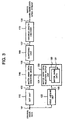
- Fig. 3 is a block diagram showing a constitution of a digital data encode system according to a second example.
- the encode system of the example comprises a DCT unit 110, a field judging unit 120, a water mark data selection output unit 130, a water mark data inserting device 140, and a quantizing unit 160, and a variable-length encoder 170.
- Fig. 3 shows only the characteristic components of the example, while the description of other general components is not shown there.
- the encode system of the second example comprises the quantizing unit 160, receiving the water mark-embedded frequency component signal 105 supplied from the water mark data inserting device 140, for sampling and quantizing the signal data and the variable-length encoder 170 for, upon receipt of the signal 107 quantized by the quantizing unit 160, performing the variable-length encoding.
- the same numerals are attached to the DCT unit 110, the field judging unit 120, the water mark data selection output unit 130, and the water mark data inserting device 140, which are constituted in the same way as the respective components of the encode system of the first embodiment, so to omit their description.
- the quantizing unit 160 and the variable-length encoder 170 may be realized by an information processor and a storage of a personal computer, a work station, or the other computer system, under the control of the control program, similarly to the other components.
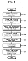
- Step 401 to 405 inserts two kinds of water mark data into the input original image data 101 by a series of processing (Steps 401 to 405) similar to the first example as described with reference to Fig. 2 , quantizes it (Step 406), and generates the water mark-embedded MPEG stream 108 to supply it finally (Step 407), as illustrated in the flow chart of Fig. 4 .
- Fig. 5 is a block diagram showing a constitution of a digital data encode system according to a third example.
- the encode system of the example comprises a DCT unit 110, a signal component judging unit 180, a water mark data inserting device 140, and an inverse DCT unit 150.
- Fig. 3 shows only the characteristic components of the example, while the description of other general components is not shown there.
- the same numerals are attached to the DCT unit 110, the water mark data inserting device 140, and the inverse DCT unit 150, which are constituted similarly to the respective components of the encode system of the first example as shown in Fig. 1 , thereby omitting their description.
- the signal component judging unit 180 and the water mark data selection output unit 190 may be realized by an information processor and a storage of a personal computer, a work station, or the other computer system, under the control of the control program, similarly to the other components.
- the signal component judging unit 180 upon receipt of the original image data 101 including Y-component(brightness component), U-component(first color-difference component), and V-component(second color-difference component), judges whether the signal components under processing is Y-signal, U-signal, or V-signal, and supplies the signal component judgement information 109 indicating the judgement result to the water mark data selection output unit 190.
- the water mark data selection output unit 190 is storing three kinds of water mark data 191, 192, and 193 which are prepared correspondingly to Y-component, U-component, and V-component. Upon receipt of the signal component judgement information 109 supplied from the signal component judging unit 180, the unit 190 selects the corresponding one of the water mark data 191, 192, and 193 according to the signal component indicated by the signal component judgement information 109 and supplies the result to the water mark data inserting device 140 as the water mark data 104.
- the signal component judging unit 180 judges the signal component of the input original image data 101 one after another (Step 602).
- the water mark data selection output unit 190 selectively assigns the water mark data corresponding to the signal component of the image data 101 and supplies the same (Step 603).
- Steps 604 to 606 Since the processing later than the spectrum resolution of the original image data 101 by the DCT unit 110 has the same operation as that later than Step 204 according to the first example as illustrated in Fig. 2 , their description is omitted (Steps 604 to 606).
- the digital data encode system of the example can obtain the water mark-embedded image data with three kinds of water mark data inserted therein correspondingly to Y-component, U-component, and V-component of the original image data 101.
- Fig. 7 is a block diagram showing a constitution of a digital data encode system according to a fourth example.
- the encode system of the example has the same structure as the encode system according to the third example as shown in Fig. 5 .
- the original image data 101 to be supplied to the DCT unit 110 and the signal component judging unit 180 is image data including R-component(red component), G-component(green component), and B-component(blue component). Therefore, the signal component judging unit 180 judges whether the signal component of the original image data 101 under processing is R-signal, G-signal, or B-signal and supplies the result as the signal component judgement information 109.
- the water mark data selection output unit 190 stores three kinds of water mark data 191, 192, and 193 prepared correspondingly to R-component, G-component, and B-component, and selects the corresponding one of the water mark data 191, 192, and 193 according to the signal component indicated by the signal component judgement information 109, so to supply the same.
- the operation of the example is similar to the operation of the third example as shown in Fig. 6 other than the processing of dividing the signal component of the original image data 101 into R-component, G-component, and B-component, thereby omitting the description thereof.
- This example can be applied to the case of forming the image data by red component (R-component), green component (G-component), and blue component (B-component) like a personal computer.
- the same method as the conventional technique 4 may be used, or other method with no need of any original image data may be used.
- the technique for extracting the water mark data inserted in the frequency components, in the existing conventional technique for extracting the water mark data may be generally applicable. Therefore, it may be used for the combination of the copy protected information included in the water mark data and the reproducing device having a particular function as mentioned in the conventional technique.
- Fig. 8 is a block diagram showing a constitution of an inserting device for inserting water mark data in image data, in the digital data encode system according to an embodiment of the present invention.
- Fig. 10 is a block diagram showing a constitution of a detecting device for detecting the water mark data inserted in the image data, in the encode system of the embodiment.
- the image data subjected to discrete cosine transform (or spectrum resolution) is overlapped with the water mark, similarly to the above-mentioned four embodiments.
- the use of the detecting device as shown in Fig. 10 enables detection of the water mark data from the water mark-embedded image data, without necessity of the original data.
- the encode system of the embodiment comprises a DCT unit 810, a water mark data inserting device 820, a water mark data table for I-picture 831, a water mark data table for P-picture 832, a water mark data table for B-picture 833, a selector 840, an encode control unit 850, and an encode unit 860.
- Fig. 8 shows only the characteristic components of the embodiment, while the description of other general components is omitted there.
- Each component of the embodiment may be realized by an information processor and a storage of a personal computer, a work station, or the other computer system, under the control of the control program, in the same way as the above-mentioned other embodiments.
- the DCT unit 810 takes out a block 102 of 8 ⁇ 8 pixels from the original image 101 that is the subject of inserting the water mark data, and performs discrete cosine transform on the image data of the block 102 (hereinafter, referred to as block image data).
- block image data As means of converting block image data in the frequency components, the spectrum resolution may be performed instead of discrete cosine transform, similarly to the above-mentioned embodiments.
- the water mark data inserting device 820 inserts proper water mark data of the water mark data stored in the water mark data table for I-picture 831, the water mark data table for P-picture 832, and the water mark data table for B-picture 833, into the frequency component signal of the block image data supplied from the DCT unit 810.
- the detailed constitution and operation of the water mark data inserting device 820 will be described below.
- the water mark data table for I-picture 831 stores the water mark data for inserting I-picture
- the water mark data table for P-picture 832 stores the water mark data for inserting P-picture
- the water mark data table for B-picture 833 stores the water mark data for inserting B-picture.
- the selector 840 selects one water mark data of the water mark data table for I-picture 831, the water mark data table for P-picture 832, and the water mark data table for B-picture 833, to supply it to the water mark data inserting device 820 according to the picture type 803 received from the encode control unit 850.
- the encode control unit 850 decides the picture type when encoding the block image data, sends the picture type signal 803 to the selector 840, and controls the encode unit 860.
- the encode unit 860 encodes the output of the water mark data inserting device 840 in accordance with MPEG under the control of the encode control unit 850, and generates and supplies the MPEG data 805.
- the original image 101 is taken out in every block of 8 ⁇ 8 pixels, and the DCT unit 810 performs the discrete cosine transform processing on the taken out data (Step 901).
- the selector 840 selects a table corresponding to the picture type, from the water mark data table for I-picture 831, the water mark data table for P-picture 832, and the water mark data table for B-picture 833, according to the picture type 803 supplied from the encode control unit 850 and supplies the water mark data 804 to the water mark data inserting device 820 (Step 902).
- the water mark data inserting device 820 inserts the water mark data 804 in the block image data converted in frequency component by the DCT unit 810 (Step 903). At this time, the water mark data inserting device 820 performs the same calculation as the above mentioned formula (2).
- the encode unit 860 quantizes and encodes the data F(i) supplied from the water mark data inserting device 820 (Step 904), and generates and supplies the MPEG data 805 with the water mark data inserted therein (Step 905).
- the water mark data detecting device of the embodiment comprises a decode unit 1010, an inverse DCT unit 1020, a display control unit 1030, a water mark data extracting unit 1040, an adder 1050, an inner product calculator 1060, a selector 1070, a water mark data table for I-picture 1081, a water mark data table for P-picture 1082, a water mark data table for B-picture 1083, and a statistical similarity calculator 1090.
- Each component of the detecting device of the embodiment may be realized by an information processor and a storage of a personal computer, a work station, or the other computer system, under the control of the control program.
- the decode unit 1010 receives the MPEG data 805 with the water mark data inserted therein, for example, supplied from the digital data encode system according to the fifth embodiment as shown in Fig. 8 , so to decode and inversely quantize it.
- the output data of the decode unit 1010 is transferred to the inverse DCT unit 1020 and the water mark data extracting unit 1040.
- the decode unit 1010 judges the picture type of the MPEG data, generates the picture type signal 1001 and supplies it to the selector 1070.
- the inverse DCT unit 1020 upon receipt of the output data of the decode unit 1010, performs the inverse discrete cosine transform processing on it, to generate and supply the image data 1004.
- the image data 1004 is supplied to the display control unit 1030.
- the water mark data extracting unit 1040 detects the data of 8 ⁇ 8 pixel block unit that may become a candidate of the water mark data, from the output data of the decode unit 1010 and supplies it. The detailed constitution and operation of the water mark data extracting unit 1040 will be described later.
- the adder 1050 upon receipt of the data of 8 ⁇ 8 pixel block unit supplied from the water mark data extracting unit 1040, adds the data together for one screen in every element and supplies the addition result.
- the selector 1070 upon receipt of the picture type signal 1001 from the decode unit 1010, selects one of the water mark data table for I-picture 1081, the water mark data table for P-picture 1082, and the water mark data table for B-picture 1083, according to the picture type indicated by the signal, and supplies the water mark data being stored therein.
- the water mark data table for I-picture 1081, the water mark data table for P-picture 1082, and the water mark data table for B-picture 1083 respectively store the same water mark data as being stored in the water mark data table for I-picture 831, the water mark data table for P-picture 832, and the water mark data table for B-picture 833 in the encode system of Fig. 8 .
- the inner product calculator 1060 upon receipt of the output data of the adder 1050 and the water mark data 1002 supplied from the selector 1070, calculates the inner product of the both data and supplies it.
- the statistical similarity calculator 1090 calculates the statistical similarity of the both data and supplies it.
- the display control unit 1030 receives the image data 1004 supplied from the inverse DCT unit 1020 and the output data 1003 of the statistical similarity calculator 1090, and performs the output control of the display data 1005 based on the image data 1004, according to the statistical similarity shown in the output data 1003. More specifically, if the statistical similarity shown in the output data 1003 is a predetermined value or the more, the unit 1030 judges that the same water mark data as the water mark data 1002 has been inserted in the MPEG data 805. When the water mark data 1002 is of the copy-protected content, the display control unit 1030 copy protects the generated image data 1004 and supplies it as the display data 1005.
- W i F i / avg F i
- i the number of each element of 8 ⁇ 8 pixel block
- F(i) the output data of the decode unit 1010
- avg(F(i)) is the partial average of the absolute values of three points around the data
- W(i) is the data that would become a candidate of the water mark data to be supplied by the water mark data extracting unit 1040.
- the decode unit 1010 upon receipt of the MPEG data 805 to be inspected, performs the decoding processing in accordance with MPEG on the received MPEG data 805 (Step 1101).
- the inverse DCT unit 1020 performs the inverse discrete cosine transform processing on the data decoded by the decode unit 1010 and generates the image data 1004 (Step 1102).
- the water mark data extracting unit 1040 receives the data F(i) of 8 ⁇ 8 pixel block supplied from the decode unit 1010, performs the calculation of the above formula (4), and extracts the data that would become a candidate of the water mark data inserted in the data F(i) (Step 1103).
- the adder 1050 does a sum of the data values for one screen in every element with respect to the extracted data of 8 ⁇ 8 pixel block unit supplied from the water mark data extracting unit 1040 (Step 1104).
- the selector 1070 selects a table corresponding to the picture type indicated in the picture type signal 1001, from the water mark data table for I-picture 1081, the water mark data table for P-picture 1082, and the water mark data table for B-picture 1083, according to the picture type signal 1001 supplied from the decode unit 1010, and supplies the water mark data 1002 to the inner product calculator 1060 (Step 1105).
- the inner product calculator 1060 calculates the inner product of the total sum of the extracted data for one screen calculated by the adder 1050 and the water mark data 1002 supplied from the selector 1070 (Step 1106).
- the statistical similarity calculator 1090 calculates the statistical similarity according to the inner product value supplied from the inner product calculator 1060 (Step 1107).
- the display control unit 1030 judges whether the same water mark data as the water mark data 1002 has been inserted in the MPEG data 805 or not, depending on the statistical similarity shown in the output data 1003 of the statistical similarity calculator 1090 (Step 1108) and performs a proper display control depending on the judgement result.
- the water mark data is detected from the MPEG data with the water mark data inserted therein and a proper operation can be performed in accordance with the content thereof.
- the detecting device of the embodiment needs no original image data in detecting the water mark data. Therefore, the detecting device can be used in the reproducing device of a general user having no original image data for the detection of the water mark data.
- the embodiment adopts MPEG data as the data to be transferred from the water mark data inserting device to the detecting device, it is needless to say that it can be applied to the other image data compression technique by the similar concept. Further, it may be constituted in that the water mark data is inserted before performing the inverse discrete cosine transform processing, thereby transferring the data as the water mark-embedded image data.
- the digital data encode system of the present invention is capable of inserting a plurality of water mark data in one image data, thereby inserting a plurality of information therein by the water mark data.
- the present invention divides the image data according to the field, signal component, and frame, and inserts each water mark data corresponding to the division by use of one water mark data inserting device, it can realize the insertion of a plurality of water mark data into one original image data at the same circuit size as the conventional digital data encode system.
- the present invention divides the image data according to the field, signal component, and frame, and inserts each different water mark data for every dividing unit, it can reduce the deterioration of the image quality compared with the case of inserting a plurality of water mark data in every division.
Description
- The present invention relates to a digital data encode system and a water mark data inserting method for inserting water mark data in the digital data signal having a series of field data.
- Recently, there has arisen the necessity of developing means for preventing illegal copying of digital data, especially digital image data, with the advance of an information processor and a communication network and the electronization of various media.
- Data encryption technique has been proposed as this kind of technique for preventing illegal copying. This digital data encryption technique is, for example, to enable it to reproduce the encrypted digital image data in only a reproducing system having a proper cryptoanalysis key when digital image data is encrypted. The conventional encryption technique, however, has such a defect that if the encryption code is once broken, it cannot protect against the illegally copying thereafter.
- Therefore, a technique by use of water mark data is proposed, as another technique for preventing illegal copying of digital data, free from such a defect as a digital encryption technique has. Water mark data (digital water mark) is the special information to be embedded in digital image data itself in order to prevent the illegal use and copying of the digital image data. It includes, for example, information for authenticating the copyright ownership and judging the infringement of the copyright, and the copy protected information for preventing illegal copying itself.
- Such water mark data to be inserted in the digital image data includes two kinds of visible water mark data and invisible water mark data. Visible water mark data means such a special character, symbol, or other data to be inserted in the image that a person who sees the image with the water mark data combined therewith may perceive the water mark visually. This kind of visible water mark data would naturally cause the deterioration of the image quality. While, it is effective in visually appealing protection against illegal copy or illegal data fluid.
- A conventional visible water mark data embedding technique is disclosed in, for example, Japanese Patent Publication Laid-Open (Kokai) No. Heisei
8-241403 conventional technique 1, when combining visible water mark data with the original image data, the water mark data is combined with the original image data in a way of changing only the brightness of the pixel corresponding to the non-transparent part of the water mark data without changing the chromaticities, of all pixels of the original data. At this time, the scaling value for changing the brightness component of a pixel is determined by the value of, for example, chromatic component, random numbers, and pixels of water mark data. - Another example of the conventional visible water mark data embedding technique is disclosed in, for example, Japanese Patent Publication Laid-Open (Kokai) No.
Heisei 5-236424 - On the other hand, invisible water mark data means such special data to be inserted in the image that a person who sees the image with the water mark data combined therewith cannot perceive the water mark visually. This kind of invisible water mark data is embedded in the original image data in consideration of causing no natural deterioration of the image quality. As is understood from this, invisible water mark data is preferable to visible water mark data under the condition that a water mark preferably exists outside of the image data to be protected.
- The water mark data inserting technique by use of an invisible water mark causes little image deterioration and when embedding special information enabling the identification of a writer as water mark data, it can specify the writer by detecting the water mark data even after illegal copying is performed. By embedding the copy protected information for disapproving copying or the copy prohibited information for prohibiting copying, in the original image data, and providing a reproducing device for reproducing the image data with a special function corresponding to the information, for example, it is possible to notify a user of the reproducing device that the image data is the copy inhibited data and to operate the special function within the reproducing device (copy protection function or the like) so as to restrict copying into VTR (Video Tape Recorder) when the reproducing device detects the copy protected information or the like.
- As the technique of embedding the invisible water mark data in digital image, there is, for example, a technique of embedding the special information as a water mark in the digital image at the least influenced portion to the image quality in the pixel data (for example, LSB (Least Significant Bit)). This kind of the conventional invisible water mark data embedding technique is disclosed in, for example, Japanese Patent Publication Laid-Open (Kokai) No.
Heisei 6-339110 - The invisible water mark data embedding technique, however, is defective in that only the water mark data is easily removed from the image data with water mark data embedded therein, without deteriorating the quality of the original image data. For example, the information corresponding to the LSB of the pixel data will be lost by use of a low pass filter. Generally, the image compression processing aims to reduce the data amount on the whole by diminishing the information amount with respect to the least influenced portion to the quality in the pixel data. Therefore, the water mark data embedded in the least influenced portion to the quality in the pixel data will be lost in the image compression processing. As mentioned above, the invisible water mark embedding technique has such a defect that it may be difficult to re-detect the water mark data in some cases.
- Therefore, a technique of embedding invisible water mark data in a digital image as well as diffusing the water mark data into the frequency spectrum after frequency conversion of the image data (hereinafter, referred to as the conventional technique 4) is presented (refer to Nikkei Electronics p.13 (no. 660) 4.22.1996). Since water mark data is embedded in the frequency component of the image data to be processed according to the conventional technique 4, the water mark data is robust against the image compression processing and the image processing such as filtering, and the water mark data won't be lost. Further, random numbers according to the normal distribution are used as the water mark data, thereby preventing the interference of the respective water mark data even in the case of embedding a plurality of water mark data. Therefore, according to the conventional technique 4, it is difficult to destroy only the water mark data without much influence to the whole image data.
- The conventional technique 4 will be, hereinafter, described with reference to
Fig. 12 . The water mark encode system according to the conventional technique 4 comprises, for example, discrete cosine transform (DCT) means 1210, water mark data output means 1230 storing thewater mark data 1231, a water markdata inserting device 1240, and inverse discrete cosine transform (inverse DCT) means 1250. The DCT is adopted here as only one example of spectrally resolving means of original image data, and any other conversion means than the DCT will do. - In thus-constituted conventional technique 4, original image data is converted into frequency components by DCT, and n piece of data indicating higher frequency value are selected, each defined as f(1), f(2), ..., f(n). On the other hand, each water mark data w(1), w(2), ..., w(n) are selected from the normal distribution having a mean value 0 and a
variance 1, and F(i)=f(i)+α| f(i) | * w(i) is calculated with respect to each i (where i=1, 2, ..., n: hereinafter in the same way). Where, α is a scaling element. At the end, the image data with the water mark data embedded therein can be obtained as the frequency components by the replacement of f(i) with F(i). - The water mark data detection according to the conventional technique 4 is performed in the following method, by way of example. The original image data and the water mark data candidate w(i) must be known values in the detecting method of the conventional technique 4. At first, the image data with the water mark data embedded therein is converted into the frequency components by use of DCT or the like, the element values corresponding to f(1), f(2), ..., f(n) having the water mark data embedded therein in the frequency band are defined as F(1), F(2), ..., F(n). By the use of f(i) and F(i), the water mark data W(i) is extracted, calculated by W(i)=(F(i)-f(i))/f(i). Next, the statistical similarity C of w(i) and W(i) is calculated by use of the inner product of vector by C = W * w / (WD * wD). Where, W = (W(1), W(2), ..., W(n)), and w = (w(1), w(2), ..., w(n)), WD is the absolute value of the vector W, and wD is the absolute value of the vector w. As the result of the above calculation, when the statistical similarity C is a particular constant value or the more, it can be judged that the above-mentioned water mark data candidate has been embedded in the image data.
- If creating the image data with the water mark embedded therein by embedding the water mark data in the original image data by use of the conventional technique 4 as mentioned above, it is effective for a writer owing the original image data to judge the illegality of the digital image data which may be illegal copy.
- The conventional technique 4 requires original image data and water mark data candidate w(i) in order to detect the water mark data as mentioned above. Therefore, it is effective for a writer owing the original image to detect any illegally-copied image data, however, a reproducing device of a terminal used by a general user, because of having no original image, cannot perform the detecting processing of the water mark data. Then, a further improved technique than the conventional technique 4 for terminal processing, especially MPEG system (hereinafter, referred to as the conventional technique 5) is proposed.
- In the conventional technique 5, original image is divided into blocks of 8 pixels × 8 pixels and the water mark data embedding and detection is performed by use of the block unit for processing. In the water mark data embedding processing, the data is defined as f(1), f(2), ..., f(n) sequentially from the lowest frequency component of AC component in the frequency band after discrete cosine transform in the MPEG encode processing, the water mark data w(1), w(2), ..., w(n) are selected from the normal distribution having a mean value 0 and a
variance 1, and F(i)=f(i)+α×avg (f(i)) × w(i) is calculated with respect to each i. Where, α is a scaling element and avg (f(i)) is a partial average obtained by averaging the absolute values of three points around f(i), for example, f(i-1), f(i), and f(i + 1). The processing later than the MPEG encode processing will be performed by replacing f(i) with F(i). - On the other hand, detection of the water mark data will be performed in the following method. This detecting method requires no original image data and that only the data candidate w(i) (where, i=1, 2, ..., n) must be a known value. In the block frequency band of blocks after inverse quantization of the MPEG decoding processing, the data from the lowest frequency component is sequentially defined as F(1), F(2), ..., F(n). The average of the absolute values of three points around F(i) is defined as the partial average avg (F(i)), the water mark data W(i) is calculated by W(i)=F(i)/avg (F(i)), and the total WF(i) of W(i) for one image is calculated for every i. By use of the inner product of vectors, the statistical similarity of w(i) and WF(i) is calculated by C=WF×w/(WFD×wD). Where, W=(WF(1), WF(2), ..., WF(n)), w=(w(1), w(2), ..., w(n)), WFD is the absolute value of the vector WF, and wD is the absolute value of the vector w. When the statistical similarity C is a particular constant value or the more, it can be judged that the water mark data has been embedded in the image data.
- Insertion of a plurality of water mark data into one original image data can be adopted in order to attach a plurality of information such as writer information and copy protected information, to one image data. The conventional techniques 4 and 5, however, is defective in making the circuit size larger because of inserting a plurality of water mark data in one original image data and increasing the processing procedure. Namely, the conventional techniques 4 and 5 disclose a technique of inserting one water mark data in one original image data, however, with no consideration taken to the case of inserting a plurality of water mark data (for example, two water mark data) in one original image data. Therefore, when inserting, for example, two water mark data therein, different
water mark data data inserting devices - Another example of the conventional technique of embedding water mark in a digital image is disclosed in Japanese Patent Publication Laid-Open (Kokai) No.
Heisei 6-315131 - The conventional technique 6, however, cannot embed the water mark information in all the frames, so that the frame with no water mark embedded therein is unable to protect against illegal copying. Since this technique is on the assumption that successive frames are of freeze-frame pictures and that there is no change on the successive frames, an area for embedding the water mark data cannot be specified in the moving images of violence action, thereby making it impossible to embed the water mark data therein.
- Further another example of the conventional technique of embedding water mark in a digital image is disclosed in, for example, Japanese Patent Publication Laid-Open (Kokai) No.
Heisei 5-30466 - However, since the conventional technique 7 embeds the water mark data in the lower frequency portion in the frequency band after frequency conversion of the image data, the water mark data can be easily removed by use of a high pass filter. When embedding the water mark data in the intensive frequency portion after frequency conversion, a filter cannot remove the water mark, but when inserting a plurality of water mark data, it cannot help deteriorating the image quality.
-
WO 96/41468 A1 WO 96/41468 A1 - An object of the present invention is to provide a digital data encode system and a water mark data inserting method capable of inserting a plurality of water mark data in one original image data.
- Another object of the present invention is, in addition to the above object, to provide a digital data encode system and a water mark data inserting method capable of inserting a plurality of water mark data in one original image data in the circuit of the same size as that of the conventional digital data encode system.
- To solve the above object, the present invention provides a digital data encode system, a digital data encode/decode system and a water mark data inserting method according to the independent claims.
- Other objects, features and advantages of the present invention will become clear from the detailed description given herebelow.
- The present invention will be understood more fully from the detailed description given herebelow and from the accompanying drawings of the preferred embodiment of the invention.
- In the drawings:
-
Fig. 1 is a block diagram showing a constitution of a digital data encode system according to a first example. -
Fig. 2 is a flow chart showing an operation of the first example. -
Fig. 3 is a block diagram showing a constitution of a digital data encode system according to a second example. -
Fig. 4 is a flow chart showing an operation of the second example. -
Fig. 5 is a block diagram showing a constitution of a digital data encode system according to a third example. -
Fig. 6 is a flow chart showing an operation of the third example. -
Fig. 7 is a block diagram showing a constitution of a digital data encode system according to a fourth example. -
Fig. 8 is a block diagram showing a constitution of a digital data encode system according to an embodiment of the present invention. -
Fig. 9 is a flow chart showing an operation of the embodiment ofFig.8 . -
Fig. 10 is a block diagram showing a constitution of a detecting device for detecting the water mark from the data having the water mark inserted therein according to the embodiment ofFig.8 . -
Fig. 11 is a flow chart showing an operation of the detecting device ofFig. 10 . -
Fig. 12 is a block diagram showing a constitutional example of the conventional digital encode system. -
Fig. 13 is a block diagram showing another constitutional example of the conventional digital data encode system. - The preferred embodiment of the present invention will be discussed hereinafter in detail with reference to the accompanying drawings.
-
Fig. 1 is a block diagram showing a constitution of a digital data encode system according to a first example. With reference toFig. 1 , the encode system of the embodiment comprises a DCT (discrete cosine transform)unit 110, afield judging unit 120, a water mark dataselection output unit 130, a water markdata inserting device 140, and an inverse DCT (inverse discrete cosine transform)unit 150.Fig. 1 shows only the characteristic components of the example, while the description of other general components is not shown there. - Each component may be realized by an information processor and a storage controlled by a computer program (hereinafter, referred to as a control program) in a personal computer, a work station or the other computer system. The information processor includes an internal memory for storing data, a signal input port, and a signal output port, and executes processing according to the control program. Any signal input port will do as far as it can receive original image data or its corresponding data, and any signal output port will do as far as it can supply the water mark-embedded image data, water mark-embedded MPEG stream, or its corresponding data. The control program can be provided stored in a magnetic disk, a semiconductor memory, or other storing medium, so to be loaded in the information processor. A storing medium is not restricted to a particular form, but will do as far as an information processor can read out therefrom.
- In the above components, upon receipt of the digital data signal (hereinafter, referred to as the original image data) 101 having a series of field data consisting of odd fields and even fields in a series of image frames, the
DCT unit 110 performs discrete cosine transform and supplies afrequency component signal 102 to the water markdata inserting device 140. The original image data having such a data structure includes a digitalized interlace signal obtained by interlaced scanning, for example, similarly to the television signal in NTSC (National Television System Committee) method. In this case, theoriginal image data 101 has a data structure where odd fields and even fields are disposed by turns. However, in the present invention, it is not restricted to this structure but it will do as far as the boundary between each field is definite. - The
field judging unit 120, upon receipt of theoriginal image data 101, judges whether the field under processing is odd field or even field, and supplies thefield judgement information 103 indicating the judgement result to the water mark dataselection output unit 130. Field may be judged by use of a synchronous signal, for example, in case of the interlaced signal as mentioned above. Alternatively, when theoriginal image data 101 has a data structure where another information for indicating odd field or even field is attached to each field, field may be judged by use of the information. Namely, it is preferable to select and change the field judgement method in thefield judging unit 120 properly according to the data structure of theoriginal image data 101. - The water mark data
selection output unit 130 is storing a first and secondwater mark data selection output unit 130, upon receipt of thefield judgement information 103 supplied from thefield judging unit 120, judges whether thefield judgement information 103 designates an odd field or an even field. Further, the water mark dataselection output unit 130 selects the firstwater mark data 131 when thefield judgement information 103 designates an odd field, and supplies it as thewater mark data 104 to the water markdata inserting device 140. While, the water mark dataselection output unit 130 selects the secondwater mark data 132 when thefield judgement information 103 designates an even field, and supplies it as thewater mark data 104 to the water markdata inserting device 140. - The water mark
data inserting device 140, upon receipt of thefrequency component signal 102 from theDCT unit 110 and thewater mark data 104 selected and supplied by the water mark dataselection output unit 130, inserts thewater mark data 104 in thefrequency component signal 102 and supplies thefrequency component signal 105 with the water mark-embedded therein to theinverse DCT unit 150. The water markdata inserting device 140 may have the same structure as the water markdata inserting device 1240 of the above-mentioned conventional technique 4. Thefrequency component signal 102 is obtained by converting theoriginal image data 101 in the frequency components, naturally including the content corresponding to the odd and even fields. Thewater mark data 104 received from the water mark dataselection output unit 130 is selected correspondingly to the field as mentioned above. According, even in the case where the water markdata inserting device 140 has the same structure as the conventional technique, if thewater mark data 104 is inserted in thefrequency component signal 102 according to the selection result of the water mark dataselection output unit 130, the firstwater mark data 131 can be embedded in the content corresponding to the odd field of theoriginal image data 101 and the secondwater mark data 132 can be embedded in the content corresponding to the even field. - Upon receipt of the water mark-embedded
frequency component signal 105 supplied from the water markdata inserting device 140, theinverse DCT unit 150 performs inverse discrete cosine transform and supplies the water mark-embeddedimage data 106. - With reference to the flow chart of
Fig. 2 , an operation of the first example will be described. As mentioned above, when realizing the encode system of the embodiment in a computer system, a control program for controlling the information processor includes, at least, instructions for the information processor performing the following respective steps, thereby making the information processor insert the water mark data in the original image data supplied from the signal input port. - At first, the first and second
water mark data water mark data - When the signal input port receives the
original image date 101, thefield judging unit 120 makes a judgement of the field with respect to the received original data one after another whether it is an odd field or an even field (Step 202). - According to the judgement result by the
field judging unit 120 inStep 202, the water mark dataselection output unit 130 selectively assigns the first water mark data to the odd field and the second water mark data to the even field and supplies as such (Step 203). - The
DCT unit 110 performs the discrete cosine transform processing on the received original image data 101 (Step 204). Any processing will do in this step as far as it is the processing of converting theoriginal image data 101 in the frequency components by the spectrum resolution. Though this step is positioned afterStep 203 inFig. 2 , it shall be actually performed simultaneously withSteps - The water mark
data inserting device 140, according to the selection result of the water mark dataselection output unit 130 inStep 203, inserts the first water mark data in the odd field and inserts the second water mark data in the even field (Step 205), in theresultant data 102 obtained through the spectrum resolution by theDCT unit 110 inStep 204. - The
inverse DCT unit 105 thereafter converts the water mark-embeddedfrequency component signal 105 supplied from the water markdata inserting device 140 into the image data and supplies the same (Step 206). - Thus, according to the digital data encode system of this example, the water mark-embedded image data with two water mark data embedded therein can be obtained. Further, according the example, two water mark data can be inserted by the use of one water mark data inserting device. Therefore, two water mark data can be inserted by use of the same circuit size as the conventional technique 4.
- To make the description clearly, this embodiment has been described with individual functions as the
DCT unit 110, thefield judging unit 120, the water mark dataselection output unit 130, and the water markdata inserting device 140. Otherwise they may be all integrated in water mark data inserting means. At this time, the signal supplied from the water mark data inserting means is the same as the water mark-embeddedfrequency component signal 105 supplied from the water markdata inserting device 140. If the water mark data inserting means includes theinverse DCT unit 150, the signal supplied from the water mark data inserting means is the same as the water mark-embeddedimage data 106. - Though the
DCT unit 110 is adopted here, by way of an example of means for supplying the resolution signal (frequency component signal 102) through the spectrum resolution, any means will do as far as it can convert the input signal in the frequency components. -
Fig. 3 is a block diagram showing a constitution of a digital data encode system according to a second example. With reference toFig. 3 , the encode system of the example comprises aDCT unit 110, afield judging unit 120, a water mark dataselection output unit 130, a water markdata inserting device 140, and aquantizing unit 160, and a variable-length encoder 170.Fig. 3 shows only the characteristic components of the example, while the description of other general components is not shown there. - Instead of the
inverse DCT unit 150 in the encode system of the first example as shown inFig. 1 , the encode system of the second example comprises thequantizing unit 160, receiving the water mark-embeddedfrequency component signal 105 supplied from the water markdata inserting device 140, for sampling and quantizing the signal data and the variable-length encoder 170 for, upon receipt of thesignal 107 quantized by thequantizing unit 160, performing the variable-length encoding. The same numerals are attached to theDCT unit 110, thefield judging unit 120, the water mark dataselection output unit 130, and the water markdata inserting device 140, which are constituted in the same way as the respective components of the encode system of the first embodiment, so to omit their description. Thequantizing unit 160 and the variable-length encoder 170 may be realized by an information processor and a storage of a personal computer, a work station, or the other computer system, under the control of the control program, similarly to the other components. - Thus constituted encode system of this embodiment inserts two kinds of water mark data into the input
original image data 101 by a series of processing (Steps 401 to 405) similar to the first example as described with reference toFig. 2 , quantizes it (Step 406), and generates the water mark-embeddedMPEG stream 108 to supply it finally (Step 407), as illustrated in the flow chart ofFig. 4 . - In this example, though the description has been made in the case of performing the MPEG compression with the
quantizing unit 160 and the variable-length encoder 170 disposed after the water markdata inserting device 140, it is needless to say that it can be applied to another image data compression technique in the same concept. Namely, as far as it is provided with sampling means for sampling the water mark-embeddedfrequency component signal 105 to supply the sampling signal and image data compression means for processing the sampling signal into a data compressed signal to supply the digital data compression signal with the water mark-embedded therein, it is not restricted to this constitution of the example. -
Fig. 5 is a block diagram showing a constitution of a digital data encode system according to a third example. With reference toFig. 5 , the encode system of the example comprises aDCT unit 110, a signalcomponent judging unit 180, a water markdata inserting device 140, and aninverse DCT unit 150.Fig. 3 shows only the characteristic components of the example, while the description of other general components is not shown there. - In the above constitution, the same numerals are attached to the
DCT unit 110, the water markdata inserting device 140, and theinverse DCT unit 150, which are constituted similarly to the respective components of the encode system of the first example as shown inFig. 1 , thereby omitting their description. The signalcomponent judging unit 180 and the water mark dataselection output unit 190 may be realized by an information processor and a storage of a personal computer, a work station, or the other computer system, under the control of the control program, similarly to the other components. - The signal
component judging unit 180, upon receipt of theoriginal image data 101 including Y-component(brightness component), U-component(first color-difference component), and V-component(second color-difference component), judges whether the signal components under processing is Y-signal, U-signal, or V-signal, and supplies the signalcomponent judgement information 109 indicating the judgement result to the water mark dataselection output unit 190. - The water mark data
selection output unit 190 is storing three kinds ofwater mark data component judgement information 109 supplied from the signalcomponent judging unit 180, theunit 190 selects the corresponding one of thewater mark data component judgement information 109 and supplies the result to the water markdata inserting device 140 as thewater mark data 104. - An operation of the example will be described with reference to the flow chart of
Fig. 6 . At first, three kinds ofwater mark data - When the signal input port receives the
original image data 101, the signalcomponent judging unit 180 judges the signal component of the inputoriginal image data 101 one after another (Step 602). - According to the result judged by the signal
component judging unit 180 inStep 602, the water mark dataselection output unit 190 selectively assigns the water mark data corresponding to the signal component of theimage data 101 and supplies the same (Step 603). - Since the processing later than the spectrum resolution of the
original image data 101 by theDCT unit 110 has the same operation as that later thanStep 204 according to the first example as illustrated inFig. 2 , their description is omitted (Steps 604 to 606). - As mentioned above, the digital data encode system of the example can obtain the water mark-embedded image data with three kinds of water mark data inserted therein correspondingly to Y-component, U-component, and V-component of the
original image data 101. -
Fig. 7 is a block diagram showing a constitution of a digital data encode system according to a fourth example. With reference toFig. 7 , the encode system of the example has the same structure as the encode system according to the third example as shown inFig. 5 . Where, theoriginal image data 101 to be supplied to theDCT unit 110 and the signalcomponent judging unit 180 is image data including R-component(red component), G-component(green component), and B-component(blue component). Therefore, the signalcomponent judging unit 180 judges whether the signal component of theoriginal image data 101 under processing is R-signal, G-signal, or B-signal and supplies the result as the signalcomponent judgement information 109. The water mark dataselection output unit 190 stores three kinds ofwater mark data water mark data component judgement information 109, so to supply the same. - The operation of the example is similar to the operation of the third example as shown in
Fig. 6 other than the processing of dividing the signal component of theoriginal image data 101 into R-component, G-component, and B-component, thereby omitting the description thereof. This example can be applied to the case of forming the image data by red component (R-component), green component (G-component), and blue component (B-component) like a personal computer. - As means of extracting the water mark data from the water mark-embedded image data or water mark-embedded compressed digital data generated by the above-mentioned four examples, the same method as the conventional technique 4 may be used, or other method with no need of any original image data may be used. For example, the technique for extracting the water mark data inserted in the frequency components, in the existing conventional technique for extracting the water mark data, may be generally applicable. Therefore, it may be used for the combination of the copy protected information included in the water mark data and the reproducing device having a particular function as mentioned in the conventional technique.
-
Fig. 8 is a block diagram showing a constitution of an inserting device for inserting water mark data in image data, in the digital data encode system according to an embodiment of the present invention.Fig. 10 is a block diagram showing a constitution of a detecting device for detecting the water mark data inserted in the image data, in the encode system of the embodiment. In this embodiment, the image data subjected to discrete cosine transform (or spectrum resolution) is overlapped with the water mark, similarly to the above-mentioned four embodiments. The use of the detecting device as shown inFig. 10 enables detection of the water mark data from the water mark-embedded image data, without necessity of the original data. - With reference to
Fig. 8 , the encode system of the embodiment comprises aDCT unit 810, a water markdata inserting device 820, a water mark data table for I-picture 831, a water mark data table for P-picture 832, a water mark data table for B-picture 833, aselector 840, an encodecontrol unit 850, and an encodeunit 860.Fig. 8 shows only the characteristic components of the embodiment, while the description of other general components is omitted there. Each component of the embodiment may be realized by an information processor and a storage of a personal computer, a work station, or the other computer system, under the control of the control program, in the same way as the above-mentioned other embodiments. - The
DCT unit 810 takes out ablock 102 of 8 × 8 pixels from theoriginal image 101 that is the subject of inserting the water mark data, and performs discrete cosine transform on the image data of the block 102 (hereinafter, referred to as block image data). As means of converting block image data in the frequency components, the spectrum resolution may be performed instead of discrete cosine transform, similarly to the above-mentioned embodiments. - The water mark
data inserting device 820 inserts proper water mark data of the water mark data stored in the water mark data table for I-picture 831, the water mark data table for P-picture 832, and the water mark data table for B-picture 833, into the frequency component signal of the block image data supplied from theDCT unit 810. The detailed constitution and operation of the water markdata inserting device 820 will be described below. - The water mark data table for I-
picture 831 stores the water mark data for inserting I-picture, the water mark data table for P-picture 832 stores the water mark data for inserting P-picture, and the water mark data table for B-picture 833 stores the water mark data for inserting B-picture. - The
selector 840 selects one water mark data of the water mark data table for I-picture 831, the water mark data table for P-picture 832, and the water mark data table for B-picture 833, to supply it to the water markdata inserting device 820 according to thepicture type 803 received from the encodecontrol unit 850. - The encode
control unit 850 decides the picture type when encoding the block image data, sends thepicture type signal 803 to theselector 840, and controls the encodeunit 860. - The encode
unit 860 encodes the output of the water markdata inserting device 840 in accordance with MPEG under the control of the encodecontrol unit 850, and generates and supplies theMPEG data 805. - As illustrated in
Fig. 8 , the water markdata inserting device 820 includes a partialaverage calculator 823 for calculating the partial average of the absolute values of three points around the frequency component signal of the block image data supplied by theDCT unit 810 by the following formula (1);
multiplier 821 for multiplying thewater mark data 804 to be supplied by theselector 840 and the output data of the partialaverage calculator 823, in every element, amultiplier 822 for multiplying each output element of themultiplier 821 by the constant value a for use in changing the size of the water mark, and anadder 824 for adding the output data of themultiplier 822 and the output data of theDCT unit 810 in every element. - Thus-constituted water mark
data inserting device 820 will perform the following calculation;
DCT unit 810, avg(f(i)) is the partial average of the absolute values of three points around the data, and w(i) is the value of each element of thewater mark data 804 supplied by theselector 840. - This time, an operation of the embodiment will be described with reference to the flow chart of
Fig. 9 . First, based on the processing of the ordinal MPEG compression, theoriginal image 101 is taken out in every block of 8×8 pixels, and theDCT unit 810 performs the discrete cosine transform processing on the taken out data (Step 901). - The
selector 840 selects a table corresponding to the picture type, from the water mark data table for I-picture 831, the water mark data table for P-picture 832, and the water mark data table for B-picture 833, according to thepicture type 803 supplied from the encodecontrol unit 850 and supplies thewater mark data 804 to the water mark data inserting device 820 (Step 902). - The water mark
data inserting device 820 inserts thewater mark data 804 in the block image data converted in frequency component by the DCT unit 810 (Step 903). At this time, the water markdata inserting device 820 performs the same calculation as the above mentioned formula (2). - At last, the encode
unit 860 quantizes and encodes the data F(i) supplied from the water mark data inserting device 820 (Step 904), and generates and supplies theMPEG data 805 with the water mark data inserted therein (Step 905). - The description will be made about a detecting device for detecting the water mark data from the
MPEG data 805 with the water mark data inserted therein by the digital data encode system of the embodiment. With reference toFig. 10 , the water mark data detecting device of the embodiment comprises adecode unit 1010, aninverse DCT unit 1020, adisplay control unit 1030, a water markdata extracting unit 1040, anadder 1050, aninner product calculator 1060, aselector 1070, a water mark data table for I-picture 1081, a water mark data table for P-picture 1082, a water mark data table for B-picture 1083, and astatistical similarity calculator 1090.Fig. 10 shows only the characteristic components of the detecting device of the embodiment, while the description of other general components is omitted. Each component of the detecting device of the embodiment may be realized by an information processor and a storage of a personal computer, a work station, or the other computer system, under the control of the control program. - The
decode unit 1010 receives theMPEG data 805 with the water mark data inserted therein, for example, supplied from the digital data encode system according to the fifth embodiment as shown inFig. 8 , so to decode and inversely quantize it. The output data of thedecode unit 1010 is transferred to theinverse DCT unit 1020 and the water markdata extracting unit 1040. Thedecode unit 1010 judges the picture type of the MPEG data, generates thepicture type signal 1001 and supplies it to theselector 1070. - The
inverse DCT unit 1020, upon receipt of the output data of thedecode unit 1010, performs the inverse discrete cosine transform processing on it, to generate and supply theimage data 1004. Theimage data 1004 is supplied to thedisplay control unit 1030. - The water mark
data extracting unit 1040 detects the data of 8×8 pixel block unit that may become a candidate of the water mark data, from the output data of thedecode unit 1010 and supplies it. The detailed constitution and operation of the water markdata extracting unit 1040 will be described later. - The
adder 1050, upon receipt of the data of 8 ×8 pixel block unit supplied from the water markdata extracting unit 1040, adds the data together for one screen in every element and supplies the addition result. - The
selector 1070, upon receipt of thepicture type signal 1001 from thedecode unit 1010, selects one of the water mark data table for I-picture 1081, the water mark data table for P-picture 1082, and the water mark data table for B-picture 1083, according to the picture type indicated by the signal, and supplies the water mark data being stored therein. - The water mark data table for I-
picture 1081, the water mark data table for P-picture 1082, and the water mark data table for B-picture 1083 respectively store the same water mark data as being stored in the water mark data table for I-picture 831, the water mark data table for P-picture 832, and the water mark data table for B-picture 833 in the encode system ofFig. 8 . - The
inner product calculator 1060, upon receipt of the output data of theadder 1050 and thewater mark data 1002 supplied from theselector 1070, calculates the inner product of the both data and supplies it. - Based on the inner product of the output data of the
adder 1050 and thewater mark data 1002, supplied from theinner product calculator 1060, thestatistical similarity calculator 1090 calculates the statistical similarity of the both data and supplies it. - The
display control unit 1030 receives theimage data 1004 supplied from theinverse DCT unit 1020 and theoutput data 1003 of thestatistical similarity calculator 1090, and performs the output control of thedisplay data 1005 based on theimage data 1004, according to the statistical similarity shown in theoutput data 1003. More specifically, if the statistical similarity shown in theoutput data 1003 is a predetermined value or the more, theunit 1030 judges that the same water mark data as thewater mark data 1002 has been inserted in theMPEG data 805. When thewater mark data 1002 is of the copy-protected content, thedisplay control unit 1030 copy protects the generatedimage data 1004 and supplies it as thedisplay data 1005. - As illustrated in
Fig. 10 , the water markdata extracting unit 1040 includes a partialaverage calculator 1041 for calculating the partial average of the absolute values of three points around the data of 8 ×8 pixel block unit to be supplied from thedecode unit 1010 by the following formula (3)
divider 1042 for dividing the data F(i) to be supplied from thedecode unit 1010 by the partial average avg (F(i)) to be supplied from the partialaverage calculator 1041. - Thus-constituted water mark
data extracting unit 1040 will perform the following calculation;
decode unit 1010, avg(F(i)) is the partial average of the absolute values of three points around the data, and W(i) is the data that would become a candidate of the water mark data to be supplied by the water markdata extracting unit 1040. - This time, an operation of the embodiment will be described with reference to the flow chart of
Fig. 11 . First, thedecode unit 1010, upon receipt of theMPEG data 805 to be inspected, performs the decoding processing in accordance with MPEG on the received MPEG data 805 (Step 1101). - The
inverse DCT unit 1020 performs the inverse discrete cosine transform processing on the data decoded by thedecode unit 1010 and generates the image data 1004 (Step 1102). - The water mark
data extracting unit 1040 receives the data F(i) of 8×8 pixel block supplied from thedecode unit 1010, performs the calculation of the above formula (4), and extracts the data that would become a candidate of the water mark data inserted in the data F(i) (Step 1103). - The
adder 1050 does a sum of the data values for one screen in every element with respect to the extracted data of 8×8 pixel block unit supplied from the water mark data extracting unit 1040 (Step 1104). - The
selector 1070 selects a table corresponding to the picture type indicated in thepicture type signal 1001, from the water mark data table for I-picture 1081, the water mark data table for P-picture 1082, and the water mark data table for B-picture 1083, according to thepicture type signal 1001 supplied from thedecode unit 1010, and supplies thewater mark data 1002 to the inner product calculator 1060 (Step 1105). - The
inner product calculator 1060 calculates the inner product of the total sum of the extracted data for one screen calculated by theadder 1050 and thewater mark data 1002 supplied from the selector 1070 (Step 1106). Thestatistical similarity calculator 1090 calculates the statistical similarity according to the inner product value supplied from the inner product calculator 1060 (Step 1107). - At last, the
display control unit 1030 judges whether the same water mark data as thewater mark data 1002 has been inserted in theMPEG data 805 or not, depending on the statistical similarity shown in theoutput data 1003 of the statistical similarity calculator 1090 (Step 1108) and performs a proper display control depending on the judgement result. - Thus, the water mark data is detected from the MPEG data with the water mark data inserted therein and a proper operation can be performed in accordance with the content thereof. The detecting device of the embodiment needs no original image data in detecting the water mark data. Therefore, the detecting device can be used in the reproducing device of a general user having no original image data for the detection of the water mark data.
- Though the embodiment adopts MPEG data as the data to be transferred from the water mark data inserting device to the detecting device, it is needless to say that it can be applied to the other image data compression technique by the similar concept. Further, it may be constituted in that the water mark data is inserted before performing the inverse discrete cosine transform processing, thereby transferring the data as the water mark-embedded image data.
- As set forth hereinabove, the digital data encode system of the present invention is capable of inserting a plurality of water mark data in one image data, thereby inserting a plurality of information therein by the water mark data.
- Since the present invention divides the image data according to the field, signal component, and frame, and inserts each water mark data corresponding to the division by use of one water mark data inserting device, it can realize the insertion of a plurality of water mark data into one original image data at the same circuit size as the conventional digital data encode system.
- Since the present invention divides the image data according to the field, signal component, and frame, and inserts each different water mark data for every dividing unit, it can reduce the deterioration of the image quality compared with the case of inserting a plurality of water mark data in every division.
Claims (4)
- A digital data encode system having a water mark data inserting device (820) for inserting water mark data into digital data signals, said digital data signals being of a digital data signal consisting of image frames, comprising:a discrete cosine transform means (810) for performing discrete cosine transform on the digital data signals and supplying the obtained transformed signals to said water mark data inserting device (820),a water mark data inserting control means for controlling inserting of said water mark data by said water mark data inserting device (820),a MPEG encoding means (860) for encoding the digital data signals with the water mark data inserted therein by use of said water mark data inserting device (820), andan encode controlling means (850) for deciding the I, B or P picture type and for controlling said MPEG encoding means (860) so to perform encoding processing in a plurality of kinds of picture types corresponding to encoding methods for MPEG encoding the I, B or P picture type decided by said encode controlling means (850),said water mark data inserting control means comprisingwater mark data storing means (831, 832, 833) for storing a plurality of different water mark data prepared correspondingly to a plurality of I, B or P picture types for use in said MPEG encoding means (860) and said encode controlling means (850), anda water mark data selection output means (840) for, depending on information, provided by said encode controlling means (850), on the I, B or P picture type decided by said encode controlling means (850), selecting the corresponding water mark data from said water mark data storing means (831, 832, 833) and supplying it to said water mark.data inserting device (820).
- A digital data encode system as set forth in Claim 1, whereinsaid discrete cosine transform means (810) is adapted to divide the image of the digital data signals into blocks of a predetermined size, to spectrally resolve the corresponding digital data signals in every block and to supply the obtained resolved signals to said water mark data inserting device (820) as a subject of inserting the water mark data therein,said water mark data inserting device (820) comprisinga partial average calculator (823) for calculating the average of the absolute values of three points around each element in the resolved signals supplied from said spectrally-resolving means (810), as a partial average,a first multiplier (821) for multiplying the water mark data supplied from said water mark data inserting control means by the output data of said partial average calculator (823) in every element,a second multiplier (822) for multiplying each element of the output data of said first multiplier (821) by a predetermined constant, andan adder (824) for adding the output data of said second multiplier (822) and the resolved signals supplied from said spectrally-resolving means (810) in every element.
- A digital data encode/decode system having a water mark data inserting unit including a water mark data inserting control means for inserting water mark data into digital data signals by control of a water mark data inserting device (820) and a water mark data detecting unit including a water mark data detecting means for detecting the water mark data from the digital data signals with the water mark data added thereto by said water mark data inserting unit:said digital data signals being of a digital data signal consisting of a series of image frames,said water mark data inserting unit further comprisinga discrete cosine transform means (810) for performing discrete cosine transform on the digital data signals and supplying the obtained transformed signals to said water mark data inserting device (820),an MPEG encoding means (860) for encoding the digital data signals with the water mark data inserted therein by use of said water mark data inserting device (820), andan encode controlling means (850) for deciding the I, B or P picture type and for controlling said MPEG encoding means (860) so to perform encoding processing in a plurality of kinds of I, B or P picture types decided by said encode controlling means (850) corresponding to encoding methods for MPEG encoding the I, B or P picture type decided by said encode controlling means (850),said water mark data inserting control means comprisingfirst water mark data storing means (831, 832, 833) for storing a plurality of different water mark data prepared correspondingly to a plurality of I, B or P picture types for use in said MPEG encoding means (860) and said encode controlling means (850), anda water mark data selection output means (840) for, depending on information, provided by said encode controlling means (850), on the I, B or P picture type decided by said encode controlling means (850), selecting the corresponding water mark data from said first water mark data storing means (831, 832, 833) and supplying it to said water mark data inserting device (820),said water mark detecting unit comprisinga MPEG decoding means (1010) for decoding the digital data signals encoded by said MPEG encoding means (860) of said water mark data inserting device (820), anda display controlling means (1030) for controlling display depending on the data decoded by said MPEG decoding means (1010) according to the content of the water mark data inserted in the digital data signals or according to its presence,said water mark data detecting means comprisinga water mark data extracting device (1040) for extracting candidate data, that is a candidate of the water mark data, from the data decoded by said MPEG decoding means (1010),a second water mark data storing means (1081, 1082, 1083) for storing the same water mark data as the plurality of water mark data stored in said first water mark data storing means (831, 832, 833) of said water mark data inserting control means in said water mark data inserting device (820),a water mark data selection output means (1070) for selecting the corresponding water mark data from said second water mark data storing means (1081, 1082, 1083) according to the I, B or P picture type in the encoding processing to be recognized in the decoding processing by said MPEG decoding means (1010) and supplying it, anda statistical similarity judging mean (1090) for making a comparison between the candidate data extracted by said water mark data extracting device (1040) and the water mark data supplied by said water mark data selection output means (1070), judging the statistical similarity thereof, and notifying said display controlling means (1030) of the judgment result.
- A water mark data inserting method for inserting water mark data in digital data signals by use of a water mark data inserting device, said digital data signals being of a digital data signal consisting of image frames, comprising:a step of MPEG encoding the digital signals with the water mark data inserted therein by use of said water mark data inserting device,a step of controlling said MPEG encoding including a step of deciding the I, B or P picture type so to perform encoding processing in a plurality of kinds of I, B or P picture types corresponding to encoding methods for MPEG encoding the decided I, B or P picture type,a step of storing a plurality of different water mark data prepared for every plurality of picture types corresponding to encoding methods for MPEG encoding the decided I, B or P picture type in encoding the digital data signals,a step of, depending on information, provided by encoding step, on the I, B or P picture type decided by said encode controlling, selecting the corresponding water mark data from said stored water mark data and supplying it to said water mark data inserting device,a step of spectrally resolving the digital data signals, anda step of, with respect to the frequency analyzed data, as a subject of inserting the water mark data therein, obtained as a result of the spectrum resolution in said spectrally resolving step, inserting the water mark data prepared correspondingly to the I, B or P picture type, according to the selection result in said water mark data selecting step.
Applications Claiming Priority (9)
| Application Number | Priority Date | Filing Date | Title |
|---|---|---|---|
| JP3873997 | 1997-02-24 | ||
| JP38739/97 | 1997-02-24 | ||
| JP3873997 | 1997-02-24 | ||
| JP40525/97 | 1997-02-25 | ||
| JP4052597 | 1997-02-25 | ||
| JP4052597 | 1997-02-25 | ||
| JP148014/97 | 1997-06-05 | ||
| JP14801497 | 1997-06-05 | ||
| JP14801497 | 1997-06-05 |
Publications (3)
| Publication Number | Publication Date |
|---|---|
| EP0860997A2 EP0860997A2 (en) | 1998-08-26 |
| EP0860997A3 EP0860997A3 (en) | 2000-03-01 |
| EP0860997B1 true EP0860997B1 (en) | 2008-12-10 |
Family
ID=27289923
Family Applications (1)
| Application Number | Title | Priority Date | Filing Date |
|---|---|---|---|
| EP98103047A Expired - Lifetime EP0860997B1 (en) | 1997-02-24 | 1998-02-20 | Digital data encode system |
Country Status (5)
| Country | Link |
|---|---|
| US (1) | US6175639B1 (en) |
| EP (1) | EP0860997B1 (en) |
| KR (1) | KR100329697B1 (en) |
| DE (1) | DE69840308D1 (en) |
| SG (1) | SG97761A1 (en) |
Families Citing this family (78)
| Publication number | Priority date | Publication date | Assignee | Title |
|---|---|---|---|---|
| US6993152B2 (en) * | 1994-03-17 | 2006-01-31 | Digimarc Corporation | Hiding geo-location data through arrangement of objects |
| US6590996B1 (en) | 2000-02-14 | 2003-07-08 | Digimarc Corporation | Color adaptive watermarking |
| US7006661B2 (en) * | 1995-07-27 | 2006-02-28 | Digimarc Corp | Digital watermarking systems and methods |
| US20030056103A1 (en) * | 2000-12-18 | 2003-03-20 | Levy Kenneth L. | Audio/video commerce application architectural framework |
| US6320675B1 (en) * | 1997-07-15 | 2001-11-20 | Canon Kabushiki Kaisha | Image processing apparatus and method and storage medium |
| KR100323441B1 (en) * | 1997-08-20 | 2002-06-20 | 윤종용 | Mpeg2 motion picture coding/decoding system |
| JPH11196262A (en) * | 1997-11-07 | 1999-07-21 | Matsushita Electric Ind Co Ltd | Digital information imbedding extracting device/method, and medium recording program to execute the method |
| JP3214555B2 (en) * | 1998-05-06 | 2001-10-02 | 日本電気株式会社 | Digital watermark insertion device |
| JP3201347B2 (en) * | 1998-05-15 | 2001-08-20 | 日本電気株式会社 | Image attribute change device and digital watermark device |
| JPH11339374A (en) * | 1998-05-26 | 1999-12-10 | Yamaha Corp | Digital recording device |
| JP3266569B2 (en) * | 1998-07-29 | 2002-03-18 | 日本電気株式会社 | Image attribute change system using digital watermark data |
| JP3655490B2 (en) * | 1998-09-21 | 2005-06-02 | 富士写真フイルム株式会社 | Image encryption apparatus, image encryption method, computer-readable recording medium recording an image encryption program, and computer-readable recording medium recording an image file |
| US7373513B2 (en) * | 1998-09-25 | 2008-05-13 | Digimarc Corporation | Transmarking of multimedia signals |
| US7197156B1 (en) * | 1998-09-25 | 2007-03-27 | Digimarc Corporation | Method and apparatus for embedding auxiliary information within original data |
| KR100351485B1 (en) | 1998-10-08 | 2002-09-05 | 마츠시타 덴끼 산교 가부시키가이샤 | Data processor and data recorded medium |
| JP2000156641A (en) * | 1998-11-20 | 2000-06-06 | Sony Corp | Additional information superimposing method, information signal duplication control method, control signal output device and information signal recorder |
| JP3868643B2 (en) * | 1998-12-03 | 2007-01-17 | 株式会社日立製作所 | Digital information duplication restriction method, digital information duplication restriction device, and digital information recording device |
| GB2345602A (en) * | 1999-01-07 | 2000-07-12 | Hewlett Packard Co | Applying digital watermarks to selected sections of data files |
| CA2260094C (en) | 1999-01-19 | 2002-10-01 | Nec Corporation | A method for inserting and detecting electronic watermark data into a digital image and a device for the same |
| EP1028585A1 (en) * | 1999-01-21 | 2000-08-16 | Nec Corporation | A method for inserting and detecting electronic watermark data into a digital image and a device for the same |
| JP3942759B2 (en) * | 1999-01-25 | 2007-07-11 | 興和株式会社 | Digital watermark embedding method, decoding method and apparatus |
| JP3636915B2 (en) * | 1999-02-22 | 2005-04-06 | ソニー株式会社 | Additional information superimposing method, additional information detecting method, additional information superimposing apparatus, and additional information detecting apparatus |
| NZ526832A (en) * | 1999-02-25 | 2004-11-26 | Macrovision Corp | Method and apparatus for enhanced audio/video services with watermarks and associated data |
| GB2386495B (en) * | 1999-03-18 | 2003-10-29 | British Broadcasting Corp | Watermarking |
| EP1465405A3 (en) * | 1999-03-18 | 2005-01-19 | British Broadcasting Corporation | Watermarking |
| EP1195047B1 (en) * | 1999-03-18 | 2004-06-23 | British Broadcasting Corporation | Watermarking |
| US6434701B1 (en) | 1999-04-06 | 2002-08-13 | Kwan Software Engineering, Inc. | System and method for digitally marking a file |
| US6792535B1 (en) | 1999-04-06 | 2004-09-14 | Kwan Software Engineering, Inc. | System and method for digitally marking a file with a removable mark |
| AU3907900A (en) * | 1999-04-06 | 2000-10-23 | Kwan Software Engineering, Inc. | System and method for digitally marking a file with a removable mark |
| JP2001008019A (en) * | 1999-06-18 | 2001-01-12 | Canon Inc | Image processing unit and its method |
| JP3342677B2 (en) * | 1999-06-22 | 2002-11-11 | インターナショナル・ビジネス・マシーンズ・コーポレーション | Content data appraisal device |
| JP2001061052A (en) | 1999-08-20 | 2001-03-06 | Nec Corp | Method for inserting electronic watermark data, its device and electronic watermark data detector |
| GB9923212D0 (en) * | 1999-10-02 | 1999-12-08 | Central Research Lab Ltd | Apparatus for, and method of, encoding code into and decoding code from a series of stored images |
| JP2001111808A (en) * | 1999-10-05 | 2001-04-20 | Nec Corp | Electronic watermark data inserting system and device |
| US6456726B1 (en) * | 1999-10-26 | 2002-09-24 | Matsushita Electric Industrial Co., Ltd. | Methods and apparatus for multi-layer data hiding |
| DE60033500T2 (en) * | 1999-11-23 | 2007-11-08 | Koninklijke Philips Electronics N.V. | WATERMARK INSERT AND DETECTION |
| JP2001189844A (en) * | 1999-12-28 | 2001-07-10 | Nec Corp | Information inserting and detecting system |
| JP3508680B2 (en) * | 2000-02-24 | 2004-03-22 | 日本電気株式会社 | Content illegal copy prevention method and system |
| EP1137250A1 (en) | 2000-03-22 | 2001-09-26 | Hewlett-Packard Company, A Delaware Corporation | Improvements relating to digital watermarks |
| EP1298915A1 (en) * | 2000-06-28 | 2003-04-02 | Sony Corporation | Additional information embedding device and additional information embedding method |
| KR100392251B1 (en) * | 2000-09-21 | 2003-07-22 | 한국전자통신연구원 | Digital Watermark Insertion Apparatus for Copyright Protection of Digital Audio/Video/Multimedia |
| GB2369947A (en) | 2000-12-07 | 2002-06-12 | Sony Uk Ltd | Embedding data in fields of an image |
| US8301453B2 (en) | 2000-12-21 | 2012-10-30 | Digimarc Corporation | Watermark synchronization signals conveying payload data |
| JP3587168B2 (en) * | 2001-01-23 | 2004-11-10 | 日本ビクター株式会社 | Digital watermark information embedding device, embedding method, digital watermark information reproducing device and reproducing method |
| US6950519B2 (en) * | 2001-03-05 | 2005-09-27 | Digimarc Corporation | Geographically watermarked imagery and methods |
| US7042470B2 (en) | 2001-03-05 | 2006-05-09 | Digimarc Corporation | Using embedded steganographic identifiers in segmented areas of geographic images and characteristics corresponding to imagery data derived from aerial platforms |
| US7061510B2 (en) * | 2001-03-05 | 2006-06-13 | Digimarc Corporation | Geo-referencing of aerial imagery using embedded image identifiers and cross-referenced data sets |
| US7098931B2 (en) | 2001-03-05 | 2006-08-29 | Digimarc Corporation | Image management system and methods using digital watermarks |
| US7197160B2 (en) * | 2001-03-05 | 2007-03-27 | Digimarc Corporation | Geographic information systems using digital watermarks |
| US6664976B2 (en) | 2001-04-18 | 2003-12-16 | Digimarc Corporation | Image management system and methods using digital watermarks |
| US9363409B2 (en) * | 2001-03-05 | 2016-06-07 | Digimarc Corporation | Image management system and methods using digital watermarks |
| US7254249B2 (en) * | 2001-03-05 | 2007-08-07 | Digimarc Corporation | Embedding location data in video |
| US7249257B2 (en) * | 2001-03-05 | 2007-07-24 | Digimarc Corporation | Digitally watermarked maps and signs and related navigational tools |
| JP2002330434A (en) * | 2001-04-27 | 2002-11-15 | Pioneer Electronic Corp | Decoder and decoding method, re-encoder and re-encoding method, information recording medium, and decoding program and re-encoding program |
| KR20030012487A (en) * | 2001-08-01 | 2003-02-12 | 주식회사 마크애니 | Moving picture transmitting/receiving apparatus and method using watermarking and hash function technique |
| US7095872B2 (en) * | 2001-08-28 | 2006-08-22 | University Of North Carolina At Charlotte | Automated digital watermarking methods using neural networks |
| US7019940B2 (en) * | 2001-09-24 | 2006-03-28 | Hewlett-Packard Development Company, L.P. | Universal cartridge magazine system and method |
| GB2383218A (en) | 2001-12-13 | 2003-06-18 | Sony Uk Ltd | Watermarking using cyclic shifting of code words |
| US20030131350A1 (en) | 2002-01-08 | 2003-07-10 | Peiffer John C. | Method and apparatus for identifying a digital audio signal |
| KR100852665B1 (en) * | 2002-01-18 | 2008-08-19 | 엘지전자 주식회사 | Digital TV and Searching Method of The Same |
| US6775394B2 (en) | 2002-03-12 | 2004-08-10 | Matsushita Electric Industrial Co., Ltd. | Digital watermarking of binary document using halftoning |
| JP3932110B2 (en) * | 2002-04-23 | 2007-06-20 | シャープ株式会社 | Image processing apparatus, image processing system, electronic information device, image processing method, control program, and readable recording medium |
| FR2840147B1 (en) * | 2002-05-24 | 2004-08-27 | France Telecom | VIDEO INTERFERENCE AND SCRAMBLING METHODS, SYSTEM, DECODER, BROADCAST SERVER, DATA MEDIUM FOR CARRYING OUT SAID METHODS |
| KR20050005531A (en) * | 2002-06-03 | 2005-01-13 | 코닌클리케 필립스 일렉트로닉스 엔.브이. | Encoding and decoding of watermarks in independent channels |
| US20050271246A1 (en) * | 2002-07-10 | 2005-12-08 | Sharma Ravi K | Watermark payload encryption methods and systems |
| WO2004038538A2 (en) | 2002-10-23 | 2004-05-06 | Nielsen Media Research, Inc. | Digital data insertion apparatus and methods for use with compressed audio/video data |
| JP4167590B2 (en) * | 2003-12-22 | 2008-10-15 | 株式会社東芝 | Image processing method |
| WO2005076985A2 (en) | 2004-02-04 | 2005-08-25 | Digimarc Corporation | Digital watermarking image signals on-chip and photographic travel logs through digital watermarking |
| TWI404419B (en) * | 2004-04-07 | 2013-08-01 | Nielsen Media Res Inc | Data insertion methods , sysytems, machine readable media and apparatus for use with compressed audio/video data |
| KR100643273B1 (en) * | 2004-05-27 | 2006-11-10 | 삼성전자주식회사 | Video watermarking method and apparatus, video content protecting method and apparatus using video watermarking |
| CN100361157C (en) * | 2005-03-31 | 2008-01-09 | 上海交通大学 | Multi-resolution quaternary wavelet phase matching method |
| JP4498970B2 (en) * | 2005-04-15 | 2010-07-07 | 三菱電機株式会社 | Encoding data changing device, changing method, and changing program |
| JP4576318B2 (en) * | 2005-10-26 | 2010-11-04 | 富士通株式会社 | Encoding device |
| JP2008085695A (en) * | 2006-09-28 | 2008-04-10 | Fujitsu Ltd | Electronic watermark embedding apparatus and detection apparatus |
| EP2234400A1 (en) * | 2009-03-23 | 2010-09-29 | Sony Corporation | Method and device for providing a multimedia content stream embedding processing information for the content |
| KR101496854B1 (en) * | 2013-03-04 | 2015-03-02 | 황선철 | Digital fingerprinting method |
| CN105721951B (en) * | 2016-01-28 | 2018-12-25 | 华为技术有限公司 | A kind of method and device of video watermark processing |
| US10504201B2 (en) * | 2017-11-29 | 2019-12-10 | Citrix Systems, Inc. | Method and apparatus for deterrence and detection of leakage during remote interactive sessions |
Family Cites Families (19)
| Publication number | Priority date | Publication date | Assignee | Title |
|---|---|---|---|---|
| US4939515A (en) * | 1988-09-30 | 1990-07-03 | General Electric Company | Digital signal encoding and decoding apparatus |
| JPH0530466A (en) | 1991-07-19 | 1993-02-05 | Sony Corp | Video signal recorder and signal recording medium |
| US5319735A (en) * | 1991-12-17 | 1994-06-07 | Bolt Beranek And Newman Inc. | Embedded signalling |
| JPH05236424A (en) | 1992-02-25 | 1993-09-10 | Matsushita Electric Ind Co Ltd | Method and device for embedding information |
| DE69319660T2 (en) * | 1992-05-22 | 1998-11-19 | Sony Corp | Disk cassette charger |
| JP3250333B2 (en) | 1993-04-02 | 2002-01-28 | ソニー株式会社 | Video signal processing method, video signal recording method, video signal reproduction method, video signal processing device, video signal recording device, and video signal reproduction device |
| JPH06315131A (en) | 1993-04-28 | 1994-11-08 | Matsushita Electric Ind Co Ltd | Information embedding device and reproducing device |
| JP3321972B2 (en) * | 1994-02-15 | 2002-09-09 | ソニー株式会社 | Digital signal recording device |
| US5493677A (en) * | 1994-06-08 | 1996-02-20 | Systems Research & Applications Corporation | Generation, archiving, and retrieval of digital images with evoked suggestion-set captions and natural language interface |
| US5659613A (en) * | 1994-06-29 | 1997-08-19 | Macrovision Corporation | Method and apparatus for copy protection for various recording media using a video finger print |
| US5530751A (en) * | 1994-06-30 | 1996-06-25 | Hewlett-Packard Company | Embedded hidden identification codes in digital objects |
| US5530759A (en) * | 1995-02-01 | 1996-06-25 | International Business Machines Corporation | Color correct digital watermarking of images |
| JPH08331567A (en) * | 1995-06-02 | 1996-12-13 | Sony Corp | Image information encoder, image information decoder, and image information recording and reproducing system |
| US5613004A (en) * | 1995-06-07 | 1997-03-18 | The Dice Company | Steganographic method and device |
| CA2184949C (en) * | 1995-09-28 | 2000-05-30 | Ingemar J. Cox | Secure spread spectrum watermarking for multimedia data |
| US5825892A (en) * | 1996-10-28 | 1998-10-20 | International Business Machines Corporation | Protecting images with an image watermark |
| US5915027A (en) * | 1996-11-05 | 1999-06-22 | Nec Research Institute | Digital watermarking |
| US5875249A (en) * | 1997-01-08 | 1999-02-23 | International Business Machines Corporation | Invisible image watermark for image verification |
| US5991426A (en) * | 1998-12-18 | 1999-11-23 | Signafy, Inc. | Field-based watermark insertion and detection |
-
1998
- 1998-02-20 EP EP98103047A patent/EP0860997B1/en not_active Expired - Lifetime
- 1998-02-20 DE DE69840308T patent/DE69840308D1/en not_active Expired - Lifetime
- 1998-02-24 KR KR1019980006991A patent/KR100329697B1/en not_active IP Right Cessation
- 1998-02-24 US US09/028,571 patent/US6175639B1/en not_active Expired - Lifetime
- 1998-02-24 SG SG9800405A patent/SG97761A1/en unknown
Also Published As
| Publication number | Publication date |
|---|---|
| EP0860997A2 (en) | 1998-08-26 |
| KR100329697B1 (en) | 2002-08-13 |
| SG97761A1 (en) | 2003-08-20 |
| EP0860997A3 (en) | 2000-03-01 |
| US6175639B1 (en) | 2001-01-16 |
| DE69840308D1 (en) | 2009-01-22 |
| KR19980071869A (en) | 1998-10-26 |
Similar Documents
| Publication | Publication Date | Title |
|---|---|---|
| EP0860997B1 (en) | Digital data encode system | |
| US7159117B2 (en) | Electronic watermark data insertion apparatus and electronic watermark data detection apparatus | |
| US6735325B2 (en) | Identification data insertion and detection system for digital data | |
| US6298142B1 (en) | Image data encoding system and image inputting apparatus | |
| US6668068B2 (en) | Image attribute altering device and electronic watermark embedding device | |
| EP1020077B1 (en) | Method and apparatus for a copy-once watermark for video recording | |
| KR100309521B1 (en) | Video data encoder | |
| US6639996B2 (en) | Image processing apparatus, image processing method and computer readable memory medium | |
| JP2001061052A (en) | Method for inserting electronic watermark data, its device and electronic watermark data detector | |
| US20020097891A1 (en) | Electronic watermarking data insertion/detection device | |
| JP3353691B2 (en) | Digital data encoding system, digital watermark data insertion method, and storage medium storing control program | |
| EP1091317B1 (en) | System and apparatus for inserting electronic watermark data | |
| CA2226719C (en) | Image data illegal use prevention system | |
| CA2230183C (en) | Digital data encode system | |
| JPH10290312A (en) | System for preventing unauthorized appropriation of image data | |
| Leiss | Time-Variant Watermarks for Digital Videos: An MPEG-Based Approach |
Legal Events
| Date | Code | Title | Description |
|---|---|---|---|
| PUAI | Public reference made under article 153(3) epc to a published international application that has entered the european phase |
Free format text: ORIGINAL CODE: 0009012 |
|
| AK | Designated contracting states |
Kind code of ref document: A2 Designated state(s): DE FR GB NL |
|
| AX | Request for extension of the european patent |
Free format text: AL;LT;LV;MK;RO;SI |
|
| PUAL | Search report despatched |
Free format text: ORIGINAL CODE: 0009013 |
|
| AK | Designated contracting states |
Kind code of ref document: A3 Designated state(s): AT BE CH DE DK ES FI FR GB GR IE IT LI LU MC NL PT SE |
|
| AX | Request for extension of the european patent |
Free format text: AL;LT;LV;MK;RO;SI |
|
| 17P | Request for examination filed |
Effective date: 20000121 |
|
| AKX | Designation fees paid |
Free format text: DE FR GB NL |
|
| 17Q | First examination report despatched |
Effective date: 20050315 |
|
| 17Q | First examination report despatched |
Effective date: 20050315 |
|
| GRAP | Despatch of communication of intention to grant a patent |
Free format text: ORIGINAL CODE: EPIDOSNIGR1 |
|
| RIN1 | Information on inventor provided before grant (corrected) |
Inventor name: WAKASU, YUTAKA Inventor name: SATOH, SHINOBU |
|
| GRAS | Grant fee paid |
Free format text: ORIGINAL CODE: EPIDOSNIGR3 |
|
| GRAA | (expected) grant |
Free format text: ORIGINAL CODE: 0009210 |
|
| AK | Designated contracting states |
Kind code of ref document: B1 Designated state(s): DE FR GB NL |
|
| REG | Reference to a national code |
Ref country code: GB Ref legal event code: FG4D |
|
| REF | Corresponds to: |
Ref document number: 69840308 Country of ref document: DE Date of ref document: 20090122 Kind code of ref document: P |
|
| PLBE | No opposition filed within time limit |
Free format text: ORIGINAL CODE: 0009261 |
|
| STAA | Information on the status of an ep patent application or granted ep patent |
Free format text: STATUS: NO OPPOSITION FILED WITHIN TIME LIMIT |
|
| 26N | No opposition filed |
Effective date: 20090911 |
|
| REG | Reference to a national code |
Ref country code: NL Ref legal event code: SD Effective date: 20110916 |
|
| REG | Reference to a national code |
Ref country code: FR Ref legal event code: TP Owner name: NEC PERSONAL COMPUTERS, LTD, JP Effective date: 20111024 |
|
| REG | Reference to a national code |
Ref country code: DE Ref legal event code: R082 Ref document number: 69840308 Country of ref document: DE Representative=s name: SAMSON & PARTNER PATENTANWAELTE MBB, DE Effective date: 20111013 Ref country code: DE Ref legal event code: R082 Ref document number: 69840308 Country of ref document: DE Representative=s name: SAMSON & PARTNER, PATENTANWAELTE, DE Effective date: 20111013 Ref country code: DE Ref legal event code: R081 Ref document number: 69840308 Country of ref document: DE Owner name: NEC PERSONAL COMPUTERS, LTD., JP Free format text: FORMER OWNER: NEC CORP., TOKYO, JP Effective date: 20111013 |
|
| REG | Reference to a national code |
Ref country code: GB Ref legal event code: 732E Free format text: REGISTERED BETWEEN 20120223 AND 20120229 |
|
| REG | Reference to a national code |
Ref country code: FR Ref legal event code: PLFP Year of fee payment: 18 |
|
| PGFP | Annual fee paid to national office [announced via postgrant information from national office to epo] |
Ref country code: NL Payment date: 20150110 Year of fee payment: 18 |
|
| PGFP | Annual fee paid to national office [announced via postgrant information from national office to epo] |
Ref country code: DE Payment date: 20150218 Year of fee payment: 18 |
|
| PGFP | Annual fee paid to national office [announced via postgrant information from national office to epo] |
Ref country code: GB Payment date: 20150218 Year of fee payment: 18 Ref country code: FR Payment date: 20150210 Year of fee payment: 18 |
|
| REG | Reference to a national code |
Ref country code: DE Ref legal event code: R119 Ref document number: 69840308 Country of ref document: DE |
|
| GBPC | Gb: european patent ceased through non-payment of renewal fee |
Effective date: 20160220 |
|
| REG | Reference to a national code |
Ref country code: NL Ref legal event code: MM Effective date: 20160301 |
|
| REG | Reference to a national code |
Ref country code: FR Ref legal event code: ST Effective date: 20161028 |
|
| PG25 | Lapsed in a contracting state [announced via postgrant information from national office to epo] |
Ref country code: GB Free format text: LAPSE BECAUSE OF NON-PAYMENT OF DUE FEES Effective date: 20160220 Ref country code: NL Free format text: LAPSE BECAUSE OF NON-PAYMENT OF DUE FEES Effective date: 20160301 Ref country code: DE Free format text: LAPSE BECAUSE OF NON-PAYMENT OF DUE FEES Effective date: 20160901 Ref country code: FR Free format text: LAPSE BECAUSE OF NON-PAYMENT OF DUE FEES Effective date: 20160229 |