EP0865601B1 - Shell-and-tube heat exchanger - Google Patents
Shell-and-tube heat exchanger Download PDFInfo
- Publication number
- EP0865601B1 EP0865601B1 EP96942713A EP96942713A EP0865601B1 EP 0865601 B1 EP0865601 B1 EP 0865601B1 EP 96942713 A EP96942713 A EP 96942713A EP 96942713 A EP96942713 A EP 96942713A EP 0865601 B1 EP0865601 B1 EP 0865601B1
- Authority
- EP
- European Patent Office
- Prior art keywords
- heat transfer
- transfer tubes
- product
- baffle plate
- heat exchanger
- Prior art date
- Legal status (The legal status is an assumption and is not a legal conclusion. Google has not performed a legal analysis and makes no representation as to the accuracy of the status listed.)
- Expired - Lifetime
Links
Images


Classifications
-
- F—MECHANICAL ENGINEERING; LIGHTING; HEATING; WEAPONS; BLASTING
- F28—HEAT EXCHANGE IN GENERAL
- F28F—DETAILS OF HEAT-EXCHANGE AND HEAT-TRANSFER APPARATUS, OF GENERAL APPLICATION
- F28F19/00—Preventing the formation of deposits or corrosion, e.g. by using filters or scrapers
- F28F19/002—Preventing the formation of deposits or corrosion, e.g. by using filters or scrapers by using inserts or attachments
-
- F—MECHANICAL ENGINEERING; LIGHTING; HEATING; WEAPONS; BLASTING
- F28—HEAT EXCHANGE IN GENERAL
- F28F—DETAILS OF HEAT-EXCHANGE AND HEAT-TRANSFER APPARATUS, OF GENERAL APPLICATION
- F28F9/00—Casings; Header boxes; Auxiliary supports for elements; Auxiliary members within casings
- F28F9/26—Arrangements for connecting different sections of heat-exchange elements, e.g. of radiators
-
- Y—GENERAL TAGGING OF NEW TECHNOLOGICAL DEVELOPMENTS; GENERAL TAGGING OF CROSS-SECTIONAL TECHNOLOGIES SPANNING OVER SEVERAL SECTIONS OF THE IPC; TECHNICAL SUBJECTS COVERED BY FORMER USPC CROSS-REFERENCE ART COLLECTIONS [XRACs] AND DIGESTS
- Y10—TECHNICAL SUBJECTS COVERED BY FORMER USPC
- Y10S—TECHNICAL SUBJECTS COVERED BY FORMER USPC CROSS-REFERENCE ART COLLECTIONS [XRACs] AND DIGESTS
- Y10S165/00—Heat exchange
- Y10S165/355—Heat exchange having separate flow passage for two distinct fluids
- Y10S165/40—Shell enclosed conduit assembly
- Y10S165/427—Manifold for tube-side fluid, i.e. parallel
Definitions
- the present invention relates to an improvement to a shell-and-tube heat exchanger according to the preamble of claim 1.
- Heat exchangers of which there are a plurality of types, are employed to heat or cool a liquid product. Using, for example, water vapour or water at different temperatures, it is possible to heat or cool to the desired level a product which is preferably in liquid form. Heat exchangers come into use in various process industries and are also common phenomena in food industries such as dairies and juice factories.
- One well-known type of heat exchanger is the so-called shell-and-tube heat exchanger which consists of one or more heat exchanger elements which are interconnected together to form a flow system.
- the heat exchanger elements consist of one or more heat transfer tubes surrounded by an outer shell or jacket tube.
- the heat transfer tubes are interconnected with one another to form product flow inserts which in turn are interconnected by means of product pipe bends in order to circulate the product which is to be heated or cooled, depending upon the process for which the heat exchanger is employed.
- the heat exchanger tubes are enclosed in shell or jacket tubes which also enclose the heat transfer medium which may consist of water at different temperatures, water vapour or other types of liquids or gases.
- One type of shell-and-tube heat exchanger is described in Swedish Patent Specification SE 501908.
- a shell-and-tube heat exchanger in accordance with the foregoing description may be employed for treating liquids containing large particles or fibres, such as, for example, orange juice with relatively long fibres. Uncut orange fibres may be as much as 20 mm in length.
- the fibrous liquid is caused to pass through the product flow inserts, the liquid from the product pipe bends must be distributed via a baffle plate into the individual heat transfer tubes.
- SE 138 362 discloses such a shell-and-tube heat exchanger with a baffle plate having rounded caps fitted on the baffle plate to ameliorate the flow of the liquid into the individual heat transfer tubes.
- these caps provide for recesses at which fibres or particles may accumulate and disturb the flow of the liquid.
- One object of the present invention is to design the tube baffles so that the fibres are not accumulated but so that a production is obtained without the risk of disruption and with a uniform fibre or particle distribution in the liquid and without intermittent pressure changes in the product.
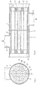
- Fig. 1 shows the principle of a shell-and-tube heat exchanger 1 in which one (or most generally several) heat exchanger elements 2 are interconnected to form a flow unit.
- Each heat exchanger element 2 consists of a number of heat transfer tubes 3 surrounded by an outer shell or jacket tube 4.
- the heat transfer tubes 3 in each shell or jacket tube 4 are united to form a product insert 5 by a tube or baffle plate 6 being disposed at each end 13 of the heat transfer tubes 3.
- the product inserts 5 with their heat transfer tubes 3 are intended to circulate the product which is to be treated in the heat exchanger 1.
- the various product inserts 5 are interconnected to one another by means of product pipe bends 7, and the outer product inserts 5 are connected to inlet and outlet conduits, respectively, for the product.
- the intention is to gather as large a number of heat transfer tubes 3 as it is possible to enclose in the shell or jacket tube 4, taking into account the product that is to be circulated.
- a product containing particles or fibres 11 requires a tube diameter of the heat transfer tubes which is between 2 and 2.5 times the size of the particles in the product. The greater the number and the smaller the size of the heat transfer tubes 3 that may be accommodated in the shell or jacket tube 4, the more efficient will be the heat transfer obtained.
- the heat transfer medium which is to be employed is enclosed, i.e. water or other liquid at various temperatures, or alternatively water vapour or other gas.
- the shell or jacket tubes 4 are in their turn interconnected with communicating angle pipe sections 8, or alternatively with inlet or outlet connections for the heat transfer medium.
- the product inserts 5 are fitted in the shell or jacket tube 4 with gaskets 9 so that product and heat transfer medium are kept discrete from one another.
- the fibres 11 in the product become oriented when they reach the baffle plate 6, such that the fibres 11 accompany the product liquid without becoming "hung” and accumulating on the baffle plate 6.
- a flow distributor The principle of a flow distributor according to the invention is shown in Fig. 12.
- a liquid flow 14 with fibres 11 of a certain maximum length L is enclosed in a duct or a tube 15.
- the liquid distributes slightly upstream of the throttle 16 so that the fibres 11 may pass through the throttle either on one side or the other.
- the throttle 16 has straight edges and is relatively narrow towards the flow direction, the fibres 11 risk becoming "hung" over the throttle 16.
- the flow distributor 12 should be of gently, non-impeding configuration and, in the preferred embodiments, consists of a semi circle.
- the radius R of the flow distributor 12, which is equal to half of the diameter D of the throttle 16, should be selected such that R constitutes at least a fourth of the maximum fibre length L. Trials have shown that, using this dimensional distribution, the fibres 11 may be caused to distribute and become oriented such that they pass the throttle 16 without fastening to it.
- the radius R of the flow distributor 12 is selected such that products with long fibres 11 may pass.
- orange juice with uncut fibres 11 may have a fibre length L of up to 25 mm, for which reason the radius R of the flow distributor 12 should, in this example, be 6.5-7 mm.
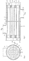
- the one baffle plate 6' of the product insert 5 is provided with flow distributors 12.
- This baffle plate 6' on the product insert 5 must therefore be turned to face towards the flow direction of the product, as illustrated in Fig. 5.
- This baffle plate 6' is designed with flow distributors 12 surrounding the ends 13 of the heat transfer tubes 3.
- the flow distributors 12 wholly and symmetrically surround the tube ends 13 so that the surface 10 of the baffle plate 6' will have the appearance of gentle funnels at the entry to the heat transfer tubes 3.
- the baffle plate 6" placed in the other end of the product insert 5 displays a completely planar surface 10.
- the flow distributors 12 are shown in the drawings as rings 17. Where the rings 17 are tangential to one another, a point 18 will be created which constitutes a part of the upper surface 10 of the baffle plate 6. The space 19 between three rings 17 has the same height as the point 18 and thus also constitutes a part of the surface 10.
- both of the baffle plates 6 on the product insert 5 are provided with flow distributors 12 which wholly and symmetrically surround the tube ends 13 of the heat transfer tubes 3.
- This construction is to be preferred when, in large scale shell-and-tube heat exchangers 1, it is often desired to switch the flow during the production cycle without consequently needing to dismantle the shell-and-tube heat exchanger 1 in order to adapt the correct plate 6' to the flow direction of the product.
- the flow distributors 12 take up a relatively large space on the baffle plate 6 since they are wholly and symmetrically to surround the ends 13 of the heat transfer tubes 3. As a result of this contributory factor, the number of heat transfer tubes 3 which can be accommodated in each respective shell or jacket tube 4 will be fewer than in a planar baffle plate 6.
- a larger number of heat transfer tubes 3 may be accommodated on each baffle plate 6.
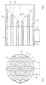
- the flow distributors 12 have here been placed asymmetrically in relation to the tube ends 13 of the heat transfer tubes 3 so that they only partly surround the tube ends 13.
- the baffle plate 6 has, at the same time, been angled in towards the centre of the plate 6.
- the surface 10 of the baffle plate 6 will thus be funnel shaped.
- the baffle plate 6 is angled at an angle ⁇ which is 45-75°, preferably 45-60°.
- the baffle plate 6 will require a slightly larger space than in the two preceding embodiments of the present invention.
- a baffle plate 6 is shown with a slightly cupped surface 10 and with flow distributors 12 which only partly surround the tube ends 13 of the heat transfer tubes 3.
- the cup-shaped surface 10 compensates for the fact that the flow distributors 12 only partly surround the tube ends 13 of the heat transfer tubes 3.
- the cupped shaped surface 10 also makes it possible for the baffle plate 6 to be shorter than is the case in the third embodiment of the present invention.
- each product insert 5 is provided with the improvement according to the present invention which should then be oriented in the inlet end of the product flow direction.
- the product then meets a surface 10 on the baffle plate 6 with gently rounded inlets to the heat transfer tubes 3, so that particles and fibres 11 readily accompany the liquid product into the heat transfer tubes 3.
- the improvement according to the present invention provides a possibility of employing a shell-and-tube heat exchanger 1 with heat transfer tubes 3 of relatively small diameters, for products which contain particles or long fibres 11.
- the present invention permits the fibres 11 to be guided gently and efficiently into the heat transfer tubes 3 without the fibres 11 running the risk of becoming accumulated on the surface 10 of the baffle plate 6.
Description
Claims (6)
- Shell-and-tube heat exchanger (1), including a product flow insert (5) consisting of a number of heat transfer tubes (3) for a product, with a baffle plate (6) disposed at each end (13) of the heat transfer tubes (3), wherein at least one of the baffle plates (6) is designed with flow distributors (12),
characterized in that,said flow distributors (12) wholly or partly surrounding the tube ends (13),said flow distributors (12) being configurated such that the surface of the flow distributors (12) facing towards the product is convex, andsaid at least one baffle plate (6) having a funnel shaped surface (10) at said ends (13) of said heat transfer tubes (3). - Heat exchanger as claimed in Claim 1, characterized in that the flow distributors (12) surround the tube ends (13) of the heat transfer tubes (3) wholly and symmetrically.
- Heat exchanger as claimed in Claim 1, characterized in that the flow distributors (12) only partly and asymmetrically surround the tube ends (13) of the heat transfer tubes (3).
- Heat exchanger as claimed in Claim 3, characterized in that the surface (10) of the baffle plate (6) is angled, with an angle α, in towards the centre of the baffle plate (6).
- Heat exchanger as claimed in Claim 4, characterized in that the angle α is 45-60°.
- Heat exchanger as claimed in Claim 3, characterized in that the surface (10) of the baffle plate (6) is cup-shaped.
Applications Claiming Priority (3)
| Application Number | Priority Date | Filing Date | Title |
|---|---|---|---|
| DK141695 | 1995-12-14 | ||
| DK141695 | 1995-12-14 | ||
| PCT/SE1996/001667 WO1997021970A1 (en) | 1995-12-14 | 1996-12-12 | Improvements to shell-and-tube heat exchangers |
Publications (2)
| Publication Number | Publication Date |
|---|---|
| EP0865601A1 EP0865601A1 (en) | 1998-09-23 |
| EP0865601B1 true EP0865601B1 (en) | 2001-05-23 |
Family
ID=8104598
Family Applications (1)
| Application Number | Title | Priority Date | Filing Date |
|---|---|---|---|
| EP96942713A Expired - Lifetime EP0865601B1 (en) | 1995-12-14 | 1996-12-12 | Shell-and-tube heat exchanger |
Country Status (12)
| Country | Link |
|---|---|
| US (1) | US5971064A (en) |
| EP (1) | EP0865601B1 (en) |
| CN (1) | CN1134647C (en) |
| AR (1) | AR005074A1 (en) |
| AT (1) | ATE201506T1 (en) |
| AU (1) | AU717525B2 (en) |
| BR (1) | BR9611946A (en) |
| DE (1) | DE69612998T2 (en) |
| DK (1) | DK0865601T3 (en) |
| EA (1) | EA000454B1 (en) |
| ES (1) | ES2157477T3 (en) |
| WO (1) | WO1997021970A1 (en) |
Families Citing this family (24)
| Publication number | Priority date | Publication date | Assignee | Title |
|---|---|---|---|---|
| SE518089C2 (en) | 1999-10-26 | 2002-08-27 | Tetra Laval Holdings & Finance | Device at a tube heat exchanger |
| DE10238205A1 (en) * | 2002-08-21 | 2004-03-04 | Bayerische Motoren Werke Ag | Heat exchanger especially compressor inter-cooler for combustion engine has cooling g pies, guide frame, with inflow and outflow apertures and chambers and protuberance in chamber wall |
| DE20307881U1 (en) * | 2003-05-21 | 2004-09-23 | Autokühler GmbH & Co. KG | Heat exchanger/charge cooler for a motor vehicle, has pipes to form a heat exchanger network, a collector with a receiver and flow-conducting elements with tapered thicknesses |
| ES2332619B1 (en) * | 2006-06-15 | 2011-06-15 | Hrs Spiratube, S.L. | HEAT EXCHANGER OF HOUSING AND COMPACT PIPES. |
| DE102006034238A1 (en) * | 2006-07-25 | 2008-01-31 | Modine Manufacturing Co., Racine | Heat exchanger comprises intercepting sewers and base plates, where orifices are formed asymmetrically and pipes are flat pipes with two narrow sides and two broadsides |
| CN100507427C (en) * | 2006-11-30 | 2009-07-01 | 郑州大学 | Inclined flow tube shell type heat exchanger |
| CN100453948C (en) * | 2007-07-20 | 2009-01-21 | 中国石化扬子石油化工有限公司 | Vertical shell-and-tube heat exchanger and its block-proof method |
| WO2009080839A1 (en) * | 2007-12-20 | 2009-07-02 | Hrs Spiratube, S.L. | Compact shell and tube heat exchanger |
| DE102008038140A1 (en) | 2008-08-18 | 2010-02-25 | Krones Ag | Tube heat exchangers, double deflector bend for tube heat exchangers, adapter for tube heat exchangers and system and method for heat transfer between at least two food streams |
| SE0802541A1 (en) * | 2008-12-09 | 2010-06-10 | Tetra Laval Holdings & Finance | Device at a tube heat exchanger |
| DE102010028117A1 (en) | 2010-04-22 | 2011-10-27 | Krones Ag | Connecting element for tubular heat exchanger |
| DE102011006653A1 (en) | 2011-04-01 | 2012-10-04 | Krones Aktiengesellschaft | Beverage heating system with integrated incinerator and method for heating beverages |
| US20120291993A1 (en) * | 2011-05-18 | 2012-11-22 | K&N Engineering, Inc. | Intercooler system |
| EP2607833A1 (en) * | 2011-12-22 | 2013-06-26 | Tetra Laval Holdings & Finance S.A. | A module for improved running time in tubular heat exchangers |
| CN102564205B (en) * | 2012-01-16 | 2014-06-11 | 杭州沈氏换热器有限公司 | Flow distributing structure of heat exchanger with micro-channels |
| EP3017259A4 (en) * | 2013-03-11 | 2017-04-26 | Hatch Pty Ltd | Shell and tube heat exchanger arrangement |
| CN104713407B (en) * | 2015-03-10 | 2017-01-25 | 江苏唯益换热器股份有限公司 | Method for distributing heat exchanger flow through micron particles |
| CN104764338A (en) * | 2015-03-19 | 2015-07-08 | 南京华电节能环保设备有限公司 | Heat pipe type smoke pulverized coal heating device |
| CN106403660B (en) * | 2016-08-31 | 2018-12-11 | 西安交通大学 | A kind of particle heat exchanger multilayer distribution and screened simultaneously |
| CN106679467B (en) * | 2017-02-28 | 2019-04-05 | 郑州大学 | Shell-and-tube heat exchanger with external bobbin carriage |
| CN106855367B (en) * | 2017-02-28 | 2024-01-26 | 郑州大学 | Shell-and-tube heat exchanger with distributed inlets and outlets |
| DE102019209222A1 (en) * | 2019-06-26 | 2020-12-31 | Krones Ag | Tubular heat exchanger |
| RU2745175C1 (en) | 2019-10-25 | 2021-03-22 | Данфосс А/С | Heat exchanger liner |
| JP2022182783A (en) * | 2021-05-28 | 2022-12-08 | 株式会社イズミフードマシナリ | Multi-tube heat exchanger |
Family Cites Families (9)
| Publication number | Priority date | Publication date | Assignee | Title |
|---|---|---|---|---|
| SE138362C1 (en) * | ||||
| SE135429C1 (en) * | ||||
| US686996A (en) * | 1901-03-15 | 1901-11-19 | Hosea Webster | Method of separating oil from exhaust-steam. |
| GB635793A (en) * | 1946-10-25 | 1950-04-19 | Andre Huet | Improvements in or relating to tubular heat exchange apparatus |
| US2655437A (en) * | 1950-06-02 | 1953-10-13 | Hydrocarbon Research Inc | Fludized solids reactor |
| US2780446A (en) * | 1953-03-04 | 1957-02-05 | Huet Andre | Heat exchangers |
| US4495987A (en) * | 1983-02-18 | 1985-01-29 | Occidental Research Corporation | Tube and tube sheet assembly |
| US4785877A (en) * | 1986-05-16 | 1988-11-22 | Santa Fe Braun Inc. | Flow streamlining device for transfer line heat exchanges |
| SE501908C2 (en) * | 1993-10-21 | 1995-06-19 | Tetra Laval Holdings & Finance | Heat exchanger with interconnected modules |
-
1996
- 1996-12-12 DE DE69612998T patent/DE69612998T2/en not_active Expired - Lifetime
- 1996-12-12 EA EA199800560A patent/EA000454B1/en not_active IP Right Cessation
- 1996-12-12 DK DK96942713T patent/DK0865601T3/en active
- 1996-12-12 EP EP96942713A patent/EP0865601B1/en not_active Expired - Lifetime
- 1996-12-12 AU AU11560/97A patent/AU717525B2/en not_active Expired
- 1996-12-12 AT AT96942713T patent/ATE201506T1/en not_active IP Right Cessation
- 1996-12-12 WO PCT/SE1996/001667 patent/WO1997021970A1/en active IP Right Grant
- 1996-12-12 US US09/077,807 patent/US5971064A/en not_active Expired - Lifetime
- 1996-12-12 CN CNB961998539A patent/CN1134647C/en not_active Expired - Lifetime
- 1996-12-12 ES ES96942713T patent/ES2157477T3/en not_active Expired - Lifetime
- 1996-12-12 BR BR9611946A patent/BR9611946A/en not_active IP Right Cessation
- 1996-12-13 AR ARP960105675A patent/AR005074A1/en unknown
Also Published As
| Publication number | Publication date |
|---|---|
| DE69612998T2 (en) | 2001-09-06 |
| DK0865601T3 (en) | 2001-08-06 |
| AU1156097A (en) | 1997-07-03 |
| CN1208463A (en) | 1999-02-17 |
| US5971064A (en) | 1999-10-26 |
| ES2157477T3 (en) | 2001-08-16 |
| EP0865601A1 (en) | 1998-09-23 |
| EA000454B1 (en) | 1999-08-26 |
| CN1134647C (en) | 2004-01-14 |
| AU717525B2 (en) | 2000-03-30 |
| ATE201506T1 (en) | 2001-06-15 |
| BR9611946A (en) | 1999-04-06 |
| DE69612998D1 (en) | 2001-06-28 |
| WO1997021970A1 (en) | 1997-06-19 |
| AR005074A1 (en) | 1999-04-07 |
| EA199800560A1 (en) | 1998-12-24 |
Similar Documents
| Publication | Publication Date | Title |
|---|---|---|
| EP0865601B1 (en) | Shell-and-tube heat exchanger | |
| US4357991A (en) | Heat exchanger having improved tube layout | |
| US20090000775A1 (en) | Shell and tube heat exchanger | |
| CA1118403A (en) | Apparatus for a treatment of flowing media which causes heat exchange and mixing | |
| US4036289A (en) | Heat exchanger tube bundle support system | |
| CA2241618A1 (en) | Tube and shell heat exchanger with baffle | |
| EP0342959B1 (en) | Heat exchanger | |
| JP2012207913A (en) | Arrangement in tube heat exchanger | |
| DE3163038D1 (en) | Annular heat exchanger | |
| US3889746A (en) | Heat exchanger | |
| US3830292A (en) | Flow distribution for heat exchangers | |
| CA2240635C (en) | Improvements to shell-and-tube heat exchangers | |
| US6817407B2 (en) | Heat exchanger with multiple exchanger blocks with uniform fluid distribution supply line and reboiler-condenser comprising such an exchanger | |
| GB2148480A (en) | Shell and tube heat exchanger | |
| EP0764810A1 (en) | Insulation and/or heating and/or colling system with prefabricated elements separated from the pipes and components of the plants through which process fluids are flowing | |
| CA2532466C (en) | Tube bundle heat exchanger | |
| WO2002065042A2 (en) | Isolation and flow direction/control plates for a heat exchanger | |
| EP0044734B1 (en) | Heat exchanger | |
| WO2010068157A1 (en) | Flow distributors in a tubular heat exchanger | |
| US5050670A (en) | Four piece elbow for a multi-tube heat exchanger | |
| RU2133004C1 (en) | Heat exchanger | |
| WO1999020969A1 (en) | A product tube bend for tube heat exchangers | |
| CN220418178U (en) | Arcuate baffle plate heat exchanger with plum blossom holes | |
| CN219798035U (en) | Anti-blocking crude oil water jacket heat exchanger | |
| JP2021528624A (en) | Heat exchanger |
Legal Events
| Date | Code | Title | Description |
|---|---|---|---|
| PUAI | Public reference made under article 153(3) epc to a published international application that has entered the european phase |
Free format text: ORIGINAL CODE: 0009012 |
|
| 17P | Request for examination filed |
Effective date: 19980615 |
|
| AK | Designated contracting states |
Kind code of ref document: A1 Designated state(s): AT BE CH DE DK ES FI FR GB GR IE IT LI LU NL PT SE |
|
| 17Q | First examination report despatched |
Effective date: 19990401 |
|
| GRAG | Despatch of communication of intention to grant |
Free format text: ORIGINAL CODE: EPIDOS AGRA |
|
| RTI1 | Title (correction) |
Free format text: SHELL-AND-TUBE HEAT EXCHANGER |
|
| RTI1 | Title (correction) |
Free format text: SHELL-AND-TUBE HEAT EXCHANGER |
|
| GRAG | Despatch of communication of intention to grant |
Free format text: ORIGINAL CODE: EPIDOS AGRA |
|
| GRAH | Despatch of communication of intention to grant a patent |
Free format text: ORIGINAL CODE: EPIDOS IGRA |
|
| GRAH | Despatch of communication of intention to grant a patent |
Free format text: ORIGINAL CODE: EPIDOS IGRA |
|
| GRAA | (expected) grant |
Free format text: ORIGINAL CODE: 0009210 |
|
| ITF | It: translation for a ep patent filed |
Owner name: STUDIO FERRARIO |
|
| AK | Designated contracting states |
Kind code of ref document: B1 Designated state(s): AT BE CH DE DK ES FI FR GB GR IE IT LI LU NL PT SE |
|
| PG25 | Lapsed in a contracting state [announced via postgrant information from national office to epo] |
Ref country code: FI Free format text: LAPSE BECAUSE OF FAILURE TO SUBMIT A TRANSLATION OF THE DESCRIPTION OR TO PAY THE FEE WITHIN THE PRESCRIBED TIME-LIMIT Effective date: 20010523 Ref country code: AT Free format text: LAPSE BECAUSE OF FAILURE TO SUBMIT A TRANSLATION OF THE DESCRIPTION OR TO PAY THE FEE WITHIN THE PRESCRIBED TIME-LIMIT Effective date: 20010523 |
|
| REF | Corresponds to: |
Ref document number: 201506 Country of ref document: AT Date of ref document: 20010615 Kind code of ref document: T |
|
| REG | Reference to a national code |
Ref country code: CH Ref legal event code: NV Representative=s name: A. BRAUN, BRAUN, HERITIER, ESCHMANN AG PATENTANWAE Ref country code: CH Ref legal event code: EP |
|
| ET | Fr: translation filed | ||
| REF | Corresponds to: |
Ref document number: 69612998 Country of ref document: DE Date of ref document: 20010628 |
|
| REG | Reference to a national code |
Ref country code: IE Ref legal event code: FG4D |
|
| REG | Reference to a national code |
Ref country code: DK Ref legal event code: T3 |
|
| REG | Reference to a national code |
Ref country code: ES Ref legal event code: FG2A Ref document number: 2157477 Country of ref document: ES Kind code of ref document: T3 |
|
| PG25 | Lapsed in a contracting state [announced via postgrant information from national office to epo] |
Ref country code: PT Free format text: LAPSE BECAUSE OF FAILURE TO SUBMIT A TRANSLATION OF THE DESCRIPTION OR TO PAY THE FEE WITHIN THE PRESCRIBED TIME-LIMIT Effective date: 20010823 |
|
| PG25 | Lapsed in a contracting state [announced via postgrant information from national office to epo] |
Ref country code: GR Free format text: LAPSE BECAUSE OF FAILURE TO SUBMIT A TRANSLATION OF THE DESCRIPTION OR TO PAY THE FEE WITHIN THE PRESCRIBED TIME-LIMIT Effective date: 20010824 |
|
| PG25 | Lapsed in a contracting state [announced via postgrant information from national office to epo] |
Ref country code: LU Free format text: LAPSE BECAUSE OF NON-PAYMENT OF DUE FEES Effective date: 20011212 Ref country code: IE Free format text: LAPSE BECAUSE OF FAILURE TO SUBMIT A TRANSLATION OF THE DESCRIPTION OR TO PAY THE FEE WITHIN THE PRESCRIBED TIME-LIMIT Effective date: 20011212 |
|
| REG | Reference to a national code |
Ref country code: GB Ref legal event code: IF02 |
|
| PLBE | No opposition filed within time limit |
Free format text: ORIGINAL CODE: 0009261 |
|
| STAA | Information on the status of an ep patent application or granted ep patent |
Free format text: STATUS: NO OPPOSITION FILED WITHIN TIME LIMIT |
|
| 26N | No opposition filed | ||
| REG | Reference to a national code |
Ref country code: IE Ref legal event code: MM4A |
|
| REG | Reference to a national code |
Ref country code: CH Ref legal event code: PFA Owner name: TETRA LAVAL HOLDINGS & FINANCE SA Free format text: TETRA LAVAL HOLDINGS & FINANCE SA#AVENUE GENERAL-GUISAN 70, P.O. BOX 430#1009 PULLY (CH) -TRANSFER TO- TETRA LAVAL HOLDINGS & FINANCE SA#AVENUE GENERAL-GUISAN 70, P.O. BOX 430#1009 PULLY (CH) |
|
| REG | Reference to a national code |
Ref country code: CH Ref legal event code: PCAR Free format text: NEW ADDRESS: HOLBEINSTRASSE 36-38, 4051 BASEL (CH) |
|
| REG | Reference to a national code |
Ref country code: FR Ref legal event code: PLFP Year of fee payment: 20 |
|
| PGFP | Annual fee paid to national office [announced via postgrant information from national office to epo] |
Ref country code: DE Payment date: 20151208 Year of fee payment: 20 Ref country code: CH Payment date: 20151211 Year of fee payment: 20 Ref country code: DK Payment date: 20151210 Year of fee payment: 20 Ref country code: GB Payment date: 20151209 Year of fee payment: 20 |
|
| PGFP | Annual fee paid to national office [announced via postgrant information from national office to epo] |
Ref country code: SE Payment date: 20151211 Year of fee payment: 20 Ref country code: NL Payment date: 20151210 Year of fee payment: 20 Ref country code: BE Payment date: 20151204 Year of fee payment: 20 Ref country code: FR Payment date: 20151110 Year of fee payment: 20 Ref country code: ES Payment date: 20151112 Year of fee payment: 20 |
|
| PGFP | Annual fee paid to national office [announced via postgrant information from national office to epo] |
Ref country code: IT Payment date: 20151221 Year of fee payment: 20 |
|
| REG | Reference to a national code |
Ref country code: DE Ref legal event code: R071 Ref document number: 69612998 Country of ref document: DE |
|
| REG | Reference to a national code |
Ref country code: NL Ref legal event code: MK Effective date: 20161211 |
|
| REG | Reference to a national code |
Ref country code: DK Ref legal event code: EUP Effective date: 20161212 |
|
| REG | Reference to a national code |
Ref country code: CH Ref legal event code: PL |
|
| REG | Reference to a national code |
Ref country code: GB Ref legal event code: PE20 Expiry date: 20161211 |
|
| PG25 | Lapsed in a contracting state [announced via postgrant information from national office to epo] |
Ref country code: GB Free format text: LAPSE BECAUSE OF EXPIRATION OF PROTECTION Effective date: 20161211 |
|
| REG | Reference to a national code |
Ref country code: SE Ref legal event code: EUG |
|
| PG25 | Lapsed in a contracting state [announced via postgrant information from national office to epo] |
Ref country code: ES Free format text: LAPSE BECAUSE OF EXPIRATION OF PROTECTION Effective date: 20161213 |