EP0865863A1 - Bifocalisation-Optics-Head - Google Patents
Bifocalisation-Optics-Head Download PDFInfo
- Publication number
- EP0865863A1 EP0865863A1 EP97400618A EP97400618A EP0865863A1 EP 0865863 A1 EP0865863 A1 EP 0865863A1 EP 97400618 A EP97400618 A EP 97400618A EP 97400618 A EP97400618 A EP 97400618A EP 0865863 A1 EP0865863 A1 EP 0865863A1
- Authority
- EP
- European Patent Office
- Prior art keywords
- parts
- points
- gives
- cut
- relative translation
- Prior art date
- Legal status (The legal status is an assumption and is not a legal conclusion. Google has not performed a legal analysis and makes no representation as to the accuracy of the status listed.)
- Withdrawn
Links
Images

Classifications
-
- B—PERFORMING OPERATIONS; TRANSPORTING
- B23—MACHINE TOOLS; METAL-WORKING NOT OTHERWISE PROVIDED FOR
- B23K—SOLDERING OR UNSOLDERING; WELDING; CLADDING OR PLATING BY SOLDERING OR WELDING; CUTTING BY APPLYING HEAT LOCALLY, e.g. FLAME CUTTING; WORKING BY LASER BEAM
- B23K26/00—Working by laser beam, e.g. welding, cutting or boring
- B23K26/02—Positioning or observing the workpiece, e.g. with respect to the point of impact; Aligning, aiming or focusing the laser beam
- B23K26/06—Shaping the laser beam, e.g. by masks or multi-focusing
- B23K26/0604—Shaping the laser beam, e.g. by masks or multi-focusing by a combination of beams
- B23K26/0608—Shaping the laser beam, e.g. by masks or multi-focusing by a combination of beams in the same heat affected zone [HAZ]
-
- B—PERFORMING OPERATIONS; TRANSPORTING
- B23—MACHINE TOOLS; METAL-WORKING NOT OTHERWISE PROVIDED FOR
- B23K—SOLDERING OR UNSOLDERING; WELDING; CLADDING OR PLATING BY SOLDERING OR WELDING; CUTTING BY APPLYING HEAT LOCALLY, e.g. FLAME CUTTING; WORKING BY LASER BEAM
- B23K26/00—Working by laser beam, e.g. welding, cutting or boring
- B23K26/02—Positioning or observing the workpiece, e.g. with respect to the point of impact; Aligning, aiming or focusing the laser beam
- B23K26/06—Shaping the laser beam, e.g. by masks or multi-focusing
- B23K26/0604—Shaping the laser beam, e.g. by masks or multi-focusing by a combination of beams
-
- B—PERFORMING OPERATIONS; TRANSPORTING
- B23—MACHINE TOOLS; METAL-WORKING NOT OTHERWISE PROVIDED FOR
- B23K—SOLDERING OR UNSOLDERING; WELDING; CLADDING OR PLATING BY SOLDERING OR WELDING; CUTTING BY APPLYING HEAT LOCALLY, e.g. FLAME CUTTING; WORKING BY LASER BEAM
- B23K26/00—Working by laser beam, e.g. welding, cutting or boring
- B23K26/02—Positioning or observing the workpiece, e.g. with respect to the point of impact; Aligning, aiming or focusing the laser beam
- B23K26/06—Shaping the laser beam, e.g. by masks or multi-focusing
- B23K26/067—Dividing the beam into multiple beams, e.g. multifocusing
Definitions
- the principle is based on the fact that a beam of light which arrives parallel to the axis of the optical device is focused at a point on this axis and if the optical devices FIGURES 1,2,3, and 4 are produced according to the invention in two parts, each part, in its section plane, comprises a half optical axis.
- the device relating to the invention has a single optical axis, as shown by way of example in FIGURE 5 .
- the device according to the invention has two distinct optical axes, as shown by way of example in FIGS. 6 and 7 .
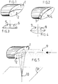
- FIGURE 5 parabolic mirror As an example of a device according to the invention, let us consider a FIGURE 5 parabolic mirror as the mirror of FIGURE 1 with an incident laser beam (9), the two parts (1) and (2) not being offset relative to each other, the incident beam (9) is focused at a single point (10) in the plane (P).
- the device according to the invention also allows, by leaving fixed in the plane (P) the position of the two focal points (11) and (12) FIGURE 6 , to make a relative distribution of the light power between a focal point and the other, by moving the laser beam perpendicular to the plane of separation of the two parts (1) and (2) FIGURE 5 , in the direction (15).
- the incident laser beam at mirror has a power of 1000 W
- this configuration will be used in welding parts to plan thickness and / or metallurgical characteristics different.
- Another advantage of the device according to the invention is to be able to increase the depth of field by almost constant numerical aperture focusing for increase for example the depth of welding, cutting or drilling.
- FIGURE 7 focusing mirror, comparable to that of FIGURE 2 which, compared to the previous example, has a plane of separation of the two parts which is rotated by 90 °, that is to say say it is contained in the incidence plan.
- the device according to the invention has its two parts (3) and (4) whose optical axis of one is superimposed on that of the other.
- the part (3) shifts from the part (4) the two optical axes slide one on the other and the single focal point gives way to two separate focal points, one (14) below on the other (13).
- the cut mirror (20) has its two half-surfaces reflecting in the same plane, the mirror of focusing (19) will give a single focal point.
- the cut mirror (20) has its two reflecting half-surfaces which are not contained in the same plane and form a dihedral whose edge is contained in their plane of separation of the two parts FIGURE 11 , the focusing mirror (19 ) will give the laser beam two focal points.
- FIGURE 12 shows by way of example the device, the focusing mirror of which has been replaced by a lens (21).
- FIGURES 10, 11 and 12 will only be applied in a limited number of cases because it induces some optical aberrations.
Abstract
Description
La présente invention concerne un dispositif optique de focalisation bifocale permettant selon le mode d'application retenu de réaliser par laser :
- des soudures bord à bord de deux pièces, par exemple le raboutage de deux tôles,
- de souder plus profondément à puissance donnée,
- de découper des épaisseurs plus grandes à puissance donnée,
- edge-to-edge welds of two pieces, for example the joining of two sheets,
- to weld more deeply at a given power,
- to cut larger thicknesses at a given power,
Dans l'industrie différents dispositifs existent pour souder ou découper, mais ils sont élaborés sur des concepts traditionnels tels, qu'il n'offrent qu'un seul point focal, ce qui impose, par exemple dans le cas du raboutage bord à bord de deux tôles par soudage, d'avoir des pièces parfaites et d'un accostage sans défaut.In the industry different devices exist for weld or cut, but they are developed on concepts traditional such that they only offer one focal point, which requires, for example in the case of edge-to-edge splicing of two sheets by welding, to have perfect parts and faultless docking.
Les réalités industrielles, conduisent à rechercher les possibilités permettant de relâcher au maximum les tolérances de fabrication. L'utilisation de cette tête de focalisation selon l'une quelconque de ses variantes exposées ci-après, offre cette possibilité.Industrial realities, lead to research the possibilities allowing maximum relaxation of the manufacturing tolerances. The use of this head focusing according to any one of its variants exposed below, offers this possibility.
L'invention a pour objet, FIGURES 1,2,3 et 4, un dispositif optomécanique qui est élaboré à partir :
- d'un miroir creux de focalisation ayant, à titre d'exemple, un profil parabolique et selon l'invention, réalisé en deux parties (1) et (2), (3) et (4) FIGURES 1 et 2,
- ou d'une lentille convergente, lentille réalisée selon l'invention en deux parties (5) et (6), (7) et (8) FIGURES 3 et 4.
- a hollow focusing mirror having, by way of example, a parabolic profile and according to the invention, produced in two parts (1) and (2), (3) and (4) FIGURES 1 and 2 ,
- or a converging lens, lens produced according to the invention in two parts (5) and (6), (7) and (8) FIGURES 3 and 4 .
Le principe repose sur le fait, qu'un faisceau de lumière qui arrive parallèlement à l'axe du dispositif optique est focalisé en un point sur cet axe et si les dispositifs optiques FIGURES 1,2,3, et 4 sont élaborés selon l'invention en deux parties, chaque partie, dans son plan de coupe, comporte un demi axe optique.The principle is based on the fact that a beam of light which arrives parallel to the axis of the optical device is focused at a point on this axis and if the optical devices FIGURES 1,2,3, and 4 are produced according to the invention in two parts, each part, in its section plane, comprises a half optical axis.
Quand les deux parties ne sont pas décalées l'une par rapport à l'autre, le dispositif se rapportant à l'invention présente un seul axe optique, comme le montre à titre d'exemple la FIGURE 5.When the two parts are not offset from each other, the device relating to the invention has a single optical axis, as shown by way of example in FIGURE 5 .
Quand les deux parties sont décalées l'une par rapport à l'autre, le dispositif selon l'invention présente deux axes optiques distincts, comme le montrent à titre d'exemple les FIGURES 6 et 7.When the two parts are offset from each other, the device according to the invention has two distinct optical axes, as shown by way of example in FIGS. 6 and 7 .
A titre d'exemple d'un dispositif selon l'invention, considérons un miroir parabolique FIGURE 5 comme le miroir de la FIGURE 1 avec un faisceau laser incident (9), les deux parties (1) et (2) n'étant pas décalées l'une par rapport à l'autre, le faisceau (9) incident est focalisé en un seul point (10) dans le plan (P).As an example of a device according to the invention, let us consider a FIGURE 5 parabolic mirror as the mirror of FIGURE 1 with an incident laser beam (9), the two parts (1) and (2) not being offset relative to each other, the incident beam (9) is focused at a single point (10) in the plane (P).
En décalant la partie (1) par rapport à la (2), le faisceau laser est focalisé simultanément en deux points (11) et (12). Figure 6By shifting part (1) relative to (2), the laser beam is focused simultaneously at two points (11) and (12). Figure 6
Le dispositif selon l'invention permet également, en laissant fixe dans le plan (P) la position des deux points de focalisation (11) et (12) FIGURE 6, de faire une répartition relative de la puissance lumineuse entre un point de focalisation et l'autre, en déplaçant le faisceau laser perpendiculairement au plan de séparation des deux parties (1) et (2) FIGURE 5, suivant la direction (15).The device according to the invention also allows, by leaving fixed in the plane (P) the position of the two focal points (11) and (12) FIGURE 6 , to make a relative distribution of the light power between a focal point and the other, by moving the laser beam perpendicular to the plane of separation of the two parts (1) and (2) FIGURE 5 , in the direction (15).
A titre d'exemple si le faisceau laser incident au miroir a une puissance de 1000 W, en faisant monter le faisceau laser vers la position (15) et parallèlement à lui même, on peut par exemple diminuer la puissance du point (11) à 300 W et d'avoir celle du point (12) à 700 W. En général cette configuration sera utilisée en soudage de pièces à rabouter d'épaisseur ou/et de caractéristiques métallurgiques différentes.For example, if the incident laser beam at mirror has a power of 1000 W, by raising the laser beam towards position (15) and parallel to it even, we can for example decrease the power of the point (11) at 300 W and to have that of point (12) at 700 W. In general this configuration will be used in welding parts to plan thickness and / or metallurgical characteristics different.
Un autre intérêt du dispositif, suivant l'invention, est de pouvoir augmenter la profondeur de champ de focalisation à ouverture numérique quasi-constante pour augmenter par exemple la profondeur de soudage, de découpe ou de perçage .Another advantage of the device according to the invention, is to be able to increase the depth of field by almost constant numerical aperture focusing for increase for example the depth of welding, cutting or drilling.
A titre d'exemple, considérons un miroir de focalisation FIGURE 7, comparable à celui de la FIGURE 2 qui, par rapport au précédent exemple, a un plan de séparation des deux parties qui est tourné de 90 °, c'est-à-dire qu'il est contenu dans le plan d'incidence. Dans cette configuration, le dispositif suivant l'invention à ses deux parties (3) et (4) dont l'axe optique de l'une est superposé sur celui de l'autre. Quand la partie (3) se décale de la partie (4), les deux axes optiques glissent l'un sur l'autre et le point de focalisation unique fait place à deux points de focalisation séparés, l'un (14) en dessous de l'autre (13).As an example, consider a FIGURE 7 focusing mirror, comparable to that of FIGURE 2 which, compared to the previous example, has a plane of separation of the two parts which is rotated by 90 °, that is to say say it is contained in the incidence plan. In this configuration, the device according to the invention has its two parts (3) and (4) whose optical axis of one is superimposed on that of the other. When the part (3) shifts from the part (4), the two optical axes slide one on the other and the single focal point gives way to two separate focal points, one (14) below on the other (13).
En déplaçant le faisceau laser (9) parallèlement à lui-même FIGURE 7 suivant la direction (16), on peut intervenir sur la répartition relative de la puissance lumineuse dans les points de focalisation tout en les laissant fixes dans la même position de l'espace.By moving the laser beam (9) parallel to itself FIGURE 7 in the direction (16), one can intervene on the relative distribution of the light power in the focal points while leaving them fixed in the same position of the space.
L'invention a donc pour objet un dispositif caractérisé :
- en ce qu'il est prévu pour les applications de soudage, de découpe, de perçage par laser et éventuellement pour le traitement thermique et les dépôts métalliques par laser.
- en ce qu'il est constitué de deux demi-miroirs de focalisation pouvant être calés en usine pour donner deux points de focalisation à des positions définies comme le montrent à titre d'exemple les FIGURES 6 et 7.
- en ce que le dispositif peut être réalisé par une lentille faite de deux parties FIGURES 3 et 4.
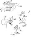
- en ce que, à chaque partie du dispositif optique est associé une mécanique de déplacement (17) manuel par vis micrométrique ou motorisé, que ce soit pour le cas des miroirs comme pour celui des lentilles.
- en ce qu'à chaque type de dispositif peut être associé une buse (18) pour confiner un gaz d'assistance d'interaction laser FIGURE 9.
- en ce qu'avec une autre variante FIGURE 10 on peut obtenir un double point de focalisation, en associant à un miroir ou à une lentille faits d'une seule partie, un miroir plan coupé en deux. En effet, comme le montre la FIGURE 10, le faisceau laser (9) qui arrive sur le miroir plan (20) fait de deux parties le réfléchit vers le miroir de focalisation (19).
- in that it is intended for welding, cutting, laser drilling applications and possibly for heat treatment and metallic deposits by laser.
- in that it consists of two focusing half-mirrors which can be calibrated at the factory to give two focusing points at defined positions as shown by way of example in FIGURES 6 and 7 .
- in that the device can be produced by a lens made up of two parts FIGURES 3 and 4 .
- in that, to each part of the optical device is associated a mechanical movement (17) manual by micrometric or motorized screw, whether for mirrors as for that of lenses.
- in that each type of device can be associated with a nozzle (18) for confining a laser interaction assistance gas FIGURE 9 .
- in that with another variant FIGURE 10 it is possible to obtain a double focal point, by associating with a mirror or with a lens made of a single part, a plane mirror cut in half. Indeed, as shown in FIGURE 10 , the laser beam (9) which arrives on the plane mirror (20) made of two parts reflects it towards the focusing mirror (19).
Si le miroir coupé (20) a ses deux demie-surfaces réfléchissantes situées dans le même plan, le miroir de focalisation (19) donnera un seul point focal.If the cut mirror (20) has its two half-surfaces reflecting in the same plane, the mirror of focusing (19) will give a single focal point.
Si le miroir coupé (20) a ses deux demi-surfaces réfléchissantes qui ne sont pas contenues dans un même plan et forment un dièdre dont l'arête est contenue dans leur plan de séparation des deux parties FIGURE 11, le miroir de focalisation (19) donnera du faisceau laser deux points focaux.If the cut mirror (20) has its two reflecting half-surfaces which are not contained in the same plane and form a dihedral whose edge is contained in their plane of separation of the two parts FIGURE 11 , the focusing mirror (19 ) will give the laser beam two focal points.
La FIGURE 12 montre à titre d'exemple le dispositif dont le miroir de focalisation a été remplacé par une lentille (21). FIGURE 12 shows by way of example the device, the focusing mirror of which has been replaced by a lens (21).
Cette dernière variante de l'invention FIGURES 10, 11 et 12 ne sera appliquée que dans un nombre de cas limités car elle induit quelques aberrations optiques.This last variant of the invention FIGURES 10, 11 and 12 will only be applied in a limited number of cases because it induces some optical aberrations.
Claims (10)
Priority Applications (1)
| Application Number | Priority Date | Filing Date | Title |
|---|---|---|---|
| EP97400618A EP0865863A1 (en) | 1997-03-19 | 1997-03-19 | Bifocalisation-Optics-Head |
Applications Claiming Priority (1)
| Application Number | Priority Date | Filing Date | Title |
|---|---|---|---|
| EP97400618A EP0865863A1 (en) | 1997-03-19 | 1997-03-19 | Bifocalisation-Optics-Head |
Publications (1)
| Publication Number | Publication Date |
|---|---|
| EP0865863A1 true EP0865863A1 (en) | 1998-09-23 |
Family
ID=8229728
Family Applications (1)
| Application Number | Title | Priority Date | Filing Date |
|---|---|---|---|
| EP97400618A Withdrawn EP0865863A1 (en) | 1997-03-19 | 1997-03-19 | Bifocalisation-Optics-Head |
Country Status (1)
| Country | Link |
|---|---|
| EP (1) | EP0865863A1 (en) |
Cited By (8)
| Publication number | Priority date | Publication date | Assignee | Title |
|---|---|---|---|---|
| US6531676B2 (en) * | 2000-01-22 | 2003-03-11 | Robert Bosch Gmbh | Method for producing an electrically conductive connection by laser radiation |
| FR2830477A1 (en) * | 2001-10-09 | 2003-04-11 | Usinor | Overlapping welding of coated metal sheets e.g., steel strip coated with zinc involves splitting high density energy beam to produce two molten metal baths and injecting neutral gas jet onto second bath to form sink at its surface |
| EP1491279A1 (en) * | 2003-06-27 | 2004-12-29 | Schuler Held Lasertechnik GmbH & Co. KG | Multifocal welding process and welding apparatus |
| EP1524096A2 (en) * | 2003-10-14 | 2005-04-20 | Denso Corporation | Resin mold and method for manufacturing the same |
| WO2009132764A1 (en) * | 2008-05-02 | 2009-11-05 | Trumpf Laser- Und Systemtechnik Gmbh | Method for laser treating work pieces by way of a laser beam and a dynamic beam control of the laser beam |
| WO2012007326A3 (en) * | 2010-07-15 | 2012-06-21 | Robert Bosch Gmbh | Structural element for an injection valve with two connected components and method for producing said structural element |
| EP2774713A1 (en) * | 2013-03-07 | 2014-09-10 | Siemens Aktiengesellschaft | Laser method with different laser beam areas within a beam and devices |
| CN113001015A (en) * | 2021-03-25 | 2021-06-22 | 连云港倍特超微粉有限公司 | Thick metal plate laser welding head based on double-focus reflector and welding method |
Citations (12)
| Publication number | Priority date | Publication date | Assignee | Title |
|---|---|---|---|---|
| EP0098048A1 (en) * | 1982-06-25 | 1984-01-11 | Philip Morris Incorporated | Beam splitter |
| US4469931A (en) * | 1982-09-13 | 1984-09-04 | Macken John A | Laser assisted saw device |
| JPS6188989A (en) * | 1984-10-05 | 1986-05-07 | Dowa Koei Kk | Butt welding method by laser beam |
| US4691093A (en) * | 1986-04-22 | 1987-09-01 | United Technologies Corporation | Twin spot laser welding |
| JPH01143785A (en) * | 1987-11-30 | 1989-06-06 | Mitsubishi Heavy Ind Ltd | Dissimilar axis multifocal point type laser beam focusing device |
| US5055653A (en) * | 1989-05-08 | 1991-10-08 | Matsushita Electric Industrial Co., Ltd. | Laser beam machining device |
| DE4024299A1 (en) * | 1990-07-31 | 1992-02-06 | Fraunhofer Ges Forschung | Multi-point optical focusing arrangement with movable faceted mirror - from which portions of incident beam are reflected with adjustable intensities to foci at variable spacing |
| JPH04182087A (en) * | 1990-11-17 | 1992-06-29 | Kobe Steel Ltd | Condensing device for laser beam machining |
| US5155323A (en) * | 1991-05-16 | 1992-10-13 | John Macken | Dual focus laser welding |
| JPH05138385A (en) * | 1991-11-14 | 1993-06-01 | Toshiba Corp | Laser beam processing method and device therefor |
| US5229572A (en) * | 1991-04-24 | 1993-07-20 | Brother Kogyo Kabushiki Kaisha | Laser processing apparatus having plural processing nozzles |
| EP0706072A2 (en) * | 1994-10-07 | 1996-04-10 | Sumitomo Electric Industries, Ltd. | Optical device for laser machining |
-
1997
- 1997-03-19 EP EP97400618A patent/EP0865863A1/en not_active Withdrawn
Patent Citations (12)
| Publication number | Priority date | Publication date | Assignee | Title |
|---|---|---|---|---|
| EP0098048A1 (en) * | 1982-06-25 | 1984-01-11 | Philip Morris Incorporated | Beam splitter |
| US4469931A (en) * | 1982-09-13 | 1984-09-04 | Macken John A | Laser assisted saw device |
| JPS6188989A (en) * | 1984-10-05 | 1986-05-07 | Dowa Koei Kk | Butt welding method by laser beam |
| US4691093A (en) * | 1986-04-22 | 1987-09-01 | United Technologies Corporation | Twin spot laser welding |
| JPH01143785A (en) * | 1987-11-30 | 1989-06-06 | Mitsubishi Heavy Ind Ltd | Dissimilar axis multifocal point type laser beam focusing device |
| US5055653A (en) * | 1989-05-08 | 1991-10-08 | Matsushita Electric Industrial Co., Ltd. | Laser beam machining device |
| DE4024299A1 (en) * | 1990-07-31 | 1992-02-06 | Fraunhofer Ges Forschung | Multi-point optical focusing arrangement with movable faceted mirror - from which portions of incident beam are reflected with adjustable intensities to foci at variable spacing |
| JPH04182087A (en) * | 1990-11-17 | 1992-06-29 | Kobe Steel Ltd | Condensing device for laser beam machining |
| US5229572A (en) * | 1991-04-24 | 1993-07-20 | Brother Kogyo Kabushiki Kaisha | Laser processing apparatus having plural processing nozzles |
| US5155323A (en) * | 1991-05-16 | 1992-10-13 | John Macken | Dual focus laser welding |
| JPH05138385A (en) * | 1991-11-14 | 1993-06-01 | Toshiba Corp | Laser beam processing method and device therefor |
| EP0706072A2 (en) * | 1994-10-07 | 1996-04-10 | Sumitomo Electric Industries, Ltd. | Optical device for laser machining |
Non-Patent Citations (4)
| Title |
|---|
| PATENT ABSTRACTS OF JAPAN vol. 010, no. 265 (M - 515) 10 September 1986 (1986-09-10) * |
| PATENT ABSTRACTS OF JAPAN vol. 013, no. 400 (M - 867) 6 September 1989 (1989-09-06) * |
| PATENT ABSTRACTS OF JAPAN vol. 016, no. 494 (M - 1324) 13 October 1992 (1992-10-13) * |
| PATENT ABSTRACTS OF JAPAN vol. 017, no. 520 (M - 1482) 20 September 1993 (1993-09-20) * |
Cited By (17)
| Publication number | Priority date | Publication date | Assignee | Title |
|---|---|---|---|---|
| US6531676B2 (en) * | 2000-01-22 | 2003-03-11 | Robert Bosch Gmbh | Method for producing an electrically conductive connection by laser radiation |
| FR2830477A1 (en) * | 2001-10-09 | 2003-04-11 | Usinor | Overlapping welding of coated metal sheets e.g., steel strip coated with zinc involves splitting high density energy beam to produce two molten metal baths and injecting neutral gas jet onto second bath to form sink at its surface |
| WO2003031111A1 (en) * | 2001-10-09 | 2003-04-17 | Usinor | Method and device for overlapping welding of two coated metal sheets with a beam of high energy density |
| US6914213B2 (en) | 2001-10-09 | 2005-07-05 | Usinor | Method and device for overlapping welding of two coated metal sheets with a beam of high energy density |
| EP1491279A1 (en) * | 2003-06-27 | 2004-12-29 | Schuler Held Lasertechnik GmbH & Co. KG | Multifocal welding process and welding apparatus |
| EP1524096A2 (en) * | 2003-10-14 | 2005-04-20 | Denso Corporation | Resin mold and method for manufacturing the same |
| EP1524096A3 (en) * | 2003-10-14 | 2008-03-19 | Denso Corporation | Resin mold and method for manufacturing the same |
| US7527760B2 (en) | 2003-10-14 | 2009-05-05 | Denso Corporation | Resin mold and method for manufacturing the same |
| WO2009132764A1 (en) * | 2008-05-02 | 2009-11-05 | Trumpf Laser- Und Systemtechnik Gmbh | Method for laser treating work pieces by way of a laser beam and a dynamic beam control of the laser beam |
| CN102015189A (en) * | 2008-05-02 | 2011-04-13 | 通快激光与系统工程有限公司 | Method for laser treating work pieces by way of a laser beam and a dynamic beam control of the laser beam |
| US8498037B2 (en) | 2008-05-02 | 2013-07-30 | Trumpf Laser—und Systemtechnik GmbH | Dynamic redirection of a laser beam |
| CN102015189B (en) * | 2008-05-02 | 2015-01-14 | 通快激光与系统工程有限公司 | Method for laser treating work pieces by way of a laser beam and a dynamic beam control of the laser beam |
| WO2012007326A3 (en) * | 2010-07-15 | 2012-06-21 | Robert Bosch Gmbh | Structural element for an injection valve with two connected components and method for producing said structural element |
| EP2774713A1 (en) * | 2013-03-07 | 2014-09-10 | Siemens Aktiengesellschaft | Laser method with different laser beam areas within a beam and devices |
| WO2014135358A1 (en) * | 2013-03-07 | 2014-09-12 | Siemens Aktiengesellschaft | Laser method with different laser beam areas within a beam and devices |
| US9884391B2 (en) | 2013-03-07 | 2018-02-06 | Siemens Aktiengesellschaft | Laser method with different laser beam areas within a beam and devices |
| CN113001015A (en) * | 2021-03-25 | 2021-06-22 | 连云港倍特超微粉有限公司 | Thick metal plate laser welding head based on double-focus reflector and welding method |
Similar Documents
| Publication | Publication Date | Title |
|---|---|---|
| US5155323A (en) | Dual focus laser welding | |
| US20140231021A1 (en) | Method and Apparatus for Three Dimensional Large Area Welding and Sealing of Optically Transparent Materials | |
| EP0131487B1 (en) | Spot welding process and installation using a laser beam | |
| JP4894025B2 (en) | Substance bonding method, substance bonding apparatus, and bonded body and manufacturing method thereof | |
| US20060186098A1 (en) | Method and apparatus for laser processing | |
| EP1273382B1 (en) | Miniaturised laser beam welding apparatus | |
| KR20150032864A (en) | Method and arrangement for creating bevels on the edges of flat glass | |
| EP2473315A1 (en) | LASER-FOCUSING HEAD WITH ZnS LENSES HAVING A PERIPHERAL THICKNESS OF AT LEAST 5 MM AND LASER CUTTING UNIT AND METHOD USING ONE SUCH FOCUSING HEAD | |
| EP0626231A1 (en) | Laser welding process of two workpieces | |
| EP0865863A1 (en) | Bifocalisation-Optics-Head | |
| JP3514129B2 (en) | Laser processing equipment | |
| EP2615486B1 (en) | Laser beam shaping apparatus | |
| EP0998369B1 (en) | Device and method for extended remote laser cutting in pulse mode | |
| FR2774319A1 (en) | METHOD FOR ADJUSTING THE POSITION OF A THERMOGRAPHIC WELDING CONTROL CAMERA | |
| FR2746047A1 (en) | Bifocal optomechanical head for laser welding and cutting | |
| FR2538916A1 (en) | Device and method for a collective preparation of optical fibres by a heat treatment | |
| US3826561A (en) | Laser pulse tailoring method and means | |
| CN110653487A (en) | Laser welding device | |
| CA3125591A1 (en) | Methods and systems for welding copper and other metals using blue lasers | |
| JP7246922B2 (en) | welding equipment | |
| KR101511670B1 (en) | Apparatus for glass cutting | |
| Hammond et al. | Diffractive optics for laser welding and bonding | |
| Ryba et al. | Unique beam delivery and processing tools for high power solid state laser processing | |
| JP2520052B2 (en) | Energy beam joining method | |
| JPH0259038B2 (en) |
Legal Events
| Date | Code | Title | Description |
|---|---|---|---|
| PUAI | Public reference made under article 153(3) epc to a published international application that has entered the european phase |
Free format text: ORIGINAL CODE: 0009012 |
|
| AK | Designated contracting states |
Kind code of ref document: A1 Designated state(s): AT BE CH DE DK ES FR GB IT LI LU SE |
|
| AKX | Designation fees paid | ||
| RBV | Designated contracting states (corrected) | ||
| 17P | Request for examination filed |
Effective date: 19990622 |
|
| RBV | Designated contracting states (corrected) |
Designated state(s): AT BE CH DE DK ES FR GB IT LI LU SE |
|
| GRAG | Despatch of communication of intention to grant |
Free format text: ORIGINAL CODE: EPIDOS AGRA |
|
| 17Q | First examination report despatched |
Effective date: 19991018 |
|
| GRAG | Despatch of communication of intention to grant |
Free format text: ORIGINAL CODE: EPIDOS AGRA |
|
| GRAH | Despatch of communication of intention to grant a patent |
Free format text: ORIGINAL CODE: EPIDOS IGRA |
|
| GRAH | Despatch of communication of intention to grant a patent |
Free format text: ORIGINAL CODE: EPIDOS IGRA |
|
| STAA | Information on the status of an ep patent application or granted ep patent |
Free format text: STATUS: THE APPLICATION IS DEEMED TO BE WITHDRAWN |
|
| 18D | Application deemed to be withdrawn |
Effective date: 20000502 |