EP0873143B1 - Improved deactivation of organisms using high-intensity pulsed polychromatic light - Google Patents
Improved deactivation of organisms using high-intensity pulsed polychromatic light Download PDFInfo
- Publication number
- EP0873143B1 EP0873143B1 EP96936466A EP96936466A EP0873143B1 EP 0873143 B1 EP0873143 B1 EP 0873143B1 EP 96936466 A EP96936466 A EP 96936466A EP 96936466 A EP96936466 A EP 96936466A EP 0873143 B1 EP0873143 B1 EP 0873143B1
- Authority
- EP
- European Patent Office
- Prior art keywords
- fluid
- baffle
- cylindrical
- tubular
- light source
- Prior art date
- Legal status (The legal status is an assumption and is not a legal conclusion. Google has not performed a legal analysis and makes no representation as to the accuracy of the status listed.)
- Expired - Lifetime
Links
- 230000009849 deactivation Effects 0.000 title description 4
- XLYOFNOQVPJJNP-UHFFFAOYSA-N water Substances O XLYOFNOQVPJJNP-UHFFFAOYSA-N 0.000 claims description 87
- 239000012530 fluid Substances 0.000 claims description 48
- 244000005700 microbiome Species 0.000 claims description 24
- 238000001816 cooling Methods 0.000 claims description 11
- 239000000463 material Substances 0.000 claims description 8
- 230000004888 barrier function Effects 0.000 claims description 5
- 238000011282 treatment Methods 0.000 description 99
- 239000003570 air Substances 0.000 description 76
- 210000003250 oocyst Anatomy 0.000 description 41
- 238000000034 method Methods 0.000 description 29
- 241000223936 Cryptosporidium parvum Species 0.000 description 24
- 239000000047 product Substances 0.000 description 24
- 239000002609 medium Substances 0.000 description 17
- 241000700605 Viruses Species 0.000 description 16
- VYPSYNLAJGMNEJ-UHFFFAOYSA-N silicon dioxide Inorganic materials O=[Si]=O VYPSYNLAJGMNEJ-UHFFFAOYSA-N 0.000 description 14
- 206010011732 Cyst Diseases 0.000 description 13
- 208000031513 cyst Diseases 0.000 description 13
- 239000010453 quartz Substances 0.000 description 13
- 239000000243 solution Substances 0.000 description 13
- 239000000725 suspension Substances 0.000 description 13
- 235000013305 food Nutrition 0.000 description 11
- 239000000523 sample Substances 0.000 description 11
- 239000005022 packaging material Substances 0.000 description 10
- 238000012545 processing Methods 0.000 description 10
- 239000007788 liquid Substances 0.000 description 9
- 210000004215 spore Anatomy 0.000 description 9
- 241000991587 Enterovirus C Species 0.000 description 8
- 230000009467 reduction Effects 0.000 description 8
- 230000001954 sterilising effect Effects 0.000 description 8
- 238000004659 sterilization and disinfection Methods 0.000 description 8
- 239000000356 contaminant Substances 0.000 description 7
- 241000699670 Mus sp. Species 0.000 description 6
- 238000005202 decontamination Methods 0.000 description 6
- 230000003588 decontaminative effect Effects 0.000 description 6
- 239000007789 gas Substances 0.000 description 6
- 230000002147 killing effect Effects 0.000 description 6
- KMUONIBRACKNSN-UHFFFAOYSA-N potassium dichromate Chemical compound [K+].[K+].[O-][Cr](=O)(=O)O[Cr]([O-])(=O)=O KMUONIBRACKNSN-UHFFFAOYSA-N 0.000 description 6
- 230000003595 spectral effect Effects 0.000 description 6
- 238000003556 assay Methods 0.000 description 4
- 239000003990 capacitor Substances 0.000 description 4
- 210000001072 colon Anatomy 0.000 description 4
- 238000013461 design Methods 0.000 description 4
- 238000010790 dilution Methods 0.000 description 4
- 239000012895 dilution Substances 0.000 description 4
- 238000009826 distribution Methods 0.000 description 4
- 230000002255 enzymatic effect Effects 0.000 description 4
- 238000001914 filtration Methods 0.000 description 4
- 238000000684 flow cytometry Methods 0.000 description 4
- 230000004907 flux Effects 0.000 description 4
- 210000000936 intestine Anatomy 0.000 description 4
- 235000021056 liquid food Nutrition 0.000 description 4
- 238000002156 mixing Methods 0.000 description 4
- CURLTUGMZLYLDI-UHFFFAOYSA-N Carbon dioxide Chemical compound O=C=O CURLTUGMZLYLDI-UHFFFAOYSA-N 0.000 description 3
- ZAMOUSCENKQFHK-UHFFFAOYSA-N Chlorine atom Chemical compound [Cl] ZAMOUSCENKQFHK-UHFFFAOYSA-N 0.000 description 3
- 241000223935 Cryptosporidium Species 0.000 description 3
- 210000004027 cell Anatomy 0.000 description 3
- 239000003795 chemical substances by application Substances 0.000 description 3
- 239000000460 chlorine Substances 0.000 description 3
- 229910052801 chlorine Inorganic materials 0.000 description 3
- 235000011389 fruit/vegetable juice Nutrition 0.000 description 3
- 208000015181 infectious disease Diseases 0.000 description 3
- 229910052751 metal Inorganic materials 0.000 description 3
- 239000002184 metal Substances 0.000 description 3
- 230000000813 microbial effect Effects 0.000 description 3
- 230000008569 process Effects 0.000 description 3
- 239000007787 solid Substances 0.000 description 3
- 238000001228 spectrum Methods 0.000 description 3
- 239000007921 spray Substances 0.000 description 3
- 239000000126 substance Substances 0.000 description 3
- IMNIMPAHZVJRPE-UHFFFAOYSA-N triethylenediamine Chemical compound C1CN2CCN1CC2 IMNIMPAHZVJRPE-UHFFFAOYSA-N 0.000 description 3
- 238000011725 BALB/c mouse Methods 0.000 description 2
- 241000194103 Bacillus pumilus Species 0.000 description 2
- LFQSCWFLJHTTHZ-UHFFFAOYSA-N Ethanol Chemical compound CCO LFQSCWFLJHTTHZ-UHFFFAOYSA-N 0.000 description 2
- 241000699666 Mus <mouse, genus> Species 0.000 description 2
- 229910019142 PO4 Inorganic materials 0.000 description 2
- 239000004372 Polyvinyl alcohol Substances 0.000 description 2
- 238000010521 absorption reaction Methods 0.000 description 2
- 238000013459 approach Methods 0.000 description 2
- 239000008366 buffered solution Substances 0.000 description 2
- 229910002092 carbon dioxide Inorganic materials 0.000 description 2
- 238000006243 chemical reaction Methods 0.000 description 2
- 230000001332 colony forming effect Effects 0.000 description 2
- 230000000994 depressogenic effect Effects 0.000 description 2
- 238000011161 development Methods 0.000 description 2
- 239000012973 diazabicyclooctane Substances 0.000 description 2
- -1 e.g. Substances 0.000 description 2
- 230000000694 effects Effects 0.000 description 2
- 238000000295 emission spectrum Methods 0.000 description 2
- 238000004146 energy storage Methods 0.000 description 2
- 238000005516 engineering process Methods 0.000 description 2
- 238000002474 experimental method Methods 0.000 description 2
- 230000002550 fecal effect Effects 0.000 description 2
- 210000001035 gastrointestinal tract Anatomy 0.000 description 2
- 239000001963 growth medium Substances 0.000 description 2
- 238000005286 illumination Methods 0.000 description 2
- 238000000338 in vitro Methods 0.000 description 2
- 230000000968 intestinal effect Effects 0.000 description 2
- 230000031700 light absorption Effects 0.000 description 2
- 230000002906 microbiologic effect Effects 0.000 description 2
- 239000000203 mixture Substances 0.000 description 2
- 238000012986 modification Methods 0.000 description 2
- 230000004048 modification Effects 0.000 description 2
- 230000003287 optical effect Effects 0.000 description 2
- 238000004806 packaging method and process Methods 0.000 description 2
- 239000002245 particle Substances 0.000 description 2
- 239000010452 phosphate Substances 0.000 description 2
- 230000000258 photobiological effect Effects 0.000 description 2
- 229920002451 polyvinyl alcohol Polymers 0.000 description 2
- 238000002360 preparation method Methods 0.000 description 2
- 238000004321 preservation Methods 0.000 description 2
- 238000010791 quenching Methods 0.000 description 2
- 230000003134 recirculating effect Effects 0.000 description 2
- 230000002829 reductive effect Effects 0.000 description 2
- 230000004044 response Effects 0.000 description 2
- 239000000758 substrate Substances 0.000 description 2
- 238000012360 testing method Methods 0.000 description 2
- 229910052724 xenon Inorganic materials 0.000 description 2
- FHNFHKCVQCLJFQ-UHFFFAOYSA-N xenon atom Chemical compound [Xe] FHNFHKCVQCLJFQ-UHFFFAOYSA-N 0.000 description 2
- 108091003079 Bovine Serum Albumin Proteins 0.000 description 1
- 239000006144 Dulbecco’s modified Eagle's medium Substances 0.000 description 1
- 241000702670 Rotavirus Species 0.000 description 1
- CZMRCDWAGMRECN-UGDNZRGBSA-N Sucrose Chemical compound O[C@H]1[C@H](O)[C@@H](CO)O[C@@]1(CO)O[C@@H]1[C@H](O)[C@@H](O)[C@H](O)[C@@H](CO)O1 CZMRCDWAGMRECN-UGDNZRGBSA-N 0.000 description 1
- 229930006000 Sucrose Natural products 0.000 description 1
- 238000002835 absorbance Methods 0.000 description 1
- 230000002411 adverse Effects 0.000 description 1
- 238000009455 aseptic packaging Methods 0.000 description 1
- 235000013361 beverage Nutrition 0.000 description 1
- 229940098773 bovine serum albumin Drugs 0.000 description 1
- 244000309466 calf Species 0.000 description 1
- 239000001569 carbon dioxide Substances 0.000 description 1
- 239000013553 cell monolayer Substances 0.000 description 1
- 238000005119 centrifugation Methods 0.000 description 1
- 238000011109 contamination Methods 0.000 description 1
- 239000013068 control sample Substances 0.000 description 1
- 239000000498 cooling water Substances 0.000 description 1
- 230000003247 decreasing effect Effects 0.000 description 1
- 230000007812 deficiency Effects 0.000 description 1
- 230000003413 degradative effect Effects 0.000 description 1
- 239000008367 deionised water Substances 0.000 description 1
- 229910021641 deionized water Inorganic materials 0.000 description 1
- 239000000645 desinfectant Substances 0.000 description 1
- 238000001514 detection method Methods 0.000 description 1
- BFMYDTVEBKDAKJ-UHFFFAOYSA-L disodium;(2',7'-dibromo-3',6'-dioxido-3-oxospiro[2-benzofuran-1,9'-xanthene]-4'-yl)mercury;hydrate Chemical group O.[Na+].[Na+].O1C(=O)C2=CC=CC=C2C21C1=CC(Br)=C([O-])C([Hg])=C1OC1=C2C=C(Br)C([O-])=C1 BFMYDTVEBKDAKJ-UHFFFAOYSA-L 0.000 description 1
- 239000000796 flavoring agent Substances 0.000 description 1
- 235000019634 flavors Nutrition 0.000 description 1
- MHMNJMPURVTYEJ-UHFFFAOYSA-N fluorescein-5-isothiocyanate Chemical compound O1C(=O)C2=CC(N=C=S)=CC=C2C21C1=CC=C(O)C=C1OC1=CC(O)=CC=C21 MHMNJMPURVTYEJ-UHFFFAOYSA-N 0.000 description 1
- 230000009246 food effect Effects 0.000 description 1
- 235000021471 food effect Nutrition 0.000 description 1
- 235000015203 fruit juice Nutrition 0.000 description 1
- 238000003384 imaging method Methods 0.000 description 1
- 238000001727 in vivo Methods 0.000 description 1
- 230000002779 inactivation Effects 0.000 description 1
- 239000011261 inert gas Substances 0.000 description 1
- 230000002458 infectious effect Effects 0.000 description 1
- 210000003734 kidney Anatomy 0.000 description 1
- 229910052743 krypton Inorganic materials 0.000 description 1
- DNNSSWSSYDEUBZ-UHFFFAOYSA-N krypton atom Chemical compound [Kr] DNNSSWSSYDEUBZ-UHFFFAOYSA-N 0.000 description 1
- 230000001665 lethal effect Effects 0.000 description 1
- 230000000670 limiting effect Effects 0.000 description 1
- 238000005259 measurement Methods 0.000 description 1
- 239000008267 milk Substances 0.000 description 1
- 235000013336 milk Nutrition 0.000 description 1
- 210000004080 milk Anatomy 0.000 description 1
- 229910052754 neon Inorganic materials 0.000 description 1
- GKAOGPIIYCISHV-UHFFFAOYSA-N neon atom Chemical compound [Ne] GKAOGPIIYCISHV-UHFFFAOYSA-N 0.000 description 1
- 210000000287 oocyte Anatomy 0.000 description 1
- 244000045947 parasite Species 0.000 description 1
- 239000011236 particulate material Substances 0.000 description 1
- NBIIXXVUZAFLBC-UHFFFAOYSA-K phosphate Chemical compound [O-]P([O-])([O-])=O NBIIXXVUZAFLBC-UHFFFAOYSA-K 0.000 description 1
- 125000002467 phosphate group Chemical group [H]OP(=O)(O[H])O[*] 0.000 description 1
- 230000000886 photobiology Effects 0.000 description 1
- 238000005086 pumping Methods 0.000 description 1
- 238000009877 rendering Methods 0.000 description 1
- 238000011160 research Methods 0.000 description 1
- 235000021055 solid food Nutrition 0.000 description 1
- 239000011343 solid material Substances 0.000 description 1
- 239000002904 solvent Substances 0.000 description 1
- 238000005507 spraying Methods 0.000 description 1
- 230000003068 static effect Effects 0.000 description 1
- 239000005720 sucrose Substances 0.000 description 1
- 239000006228 supernatant Substances 0.000 description 1
- 231100000331 toxic Toxicity 0.000 description 1
- 230000002588 toxic effect Effects 0.000 description 1
- 238000002834 transmittance Methods 0.000 description 1
- 235000013311 vegetables Nutrition 0.000 description 1
- 230000003612 virological effect Effects 0.000 description 1
- 238000005406 washing Methods 0.000 description 1
Images


Classifications
-
- H—ELECTRICITY
- H01—ELECTRIC ELEMENTS
- H01R—ELECTRICALLY-CONDUCTIVE CONNECTIONS; STRUCTURAL ASSOCIATIONS OF A PLURALITY OF MUTUALLY-INSULATED ELECTRICAL CONNECTING ELEMENTS; COUPLING DEVICES; CURRENT COLLECTORS
- H01R13/00—Details of coupling devices of the kinds covered by groups H01R12/70 or H01R24/00 - H01R33/00
- H01R13/62—Means for facilitating engagement or disengagement of coupling parts or for holding them in engagement
- H01R13/639—Additional means for holding or locking coupling parts together, after engagement, e.g. separate keylock, retainer strap
-
- A—HUMAN NECESSITIES
- A23—FOODS OR FOODSTUFFS; TREATMENT THEREOF, NOT COVERED BY OTHER CLASSES
- A23L—FOODS, FOODSTUFFS, OR NON-ALCOHOLIC BEVERAGES, NOT COVERED BY SUBCLASSES A21D OR A23B-A23J; THEIR PREPARATION OR TREATMENT, e.g. COOKING, MODIFICATION OF NUTRITIVE QUALITIES, PHYSICAL TREATMENT; PRESERVATION OF FOODS OR FOODSTUFFS, IN GENERAL
- A23L3/00—Preservation of foods or foodstuffs, in general, e.g. pasteurising, sterilising, specially adapted for foods or foodstuffs
- A23L3/26—Preservation of foods or foodstuffs, in general, e.g. pasteurising, sterilising, specially adapted for foods or foodstuffs by irradiation without heating
-
- A—HUMAN NECESSITIES
- A61—MEDICAL OR VETERINARY SCIENCE; HYGIENE
- A61L—METHODS OR APPARATUS FOR STERILISING MATERIALS OR OBJECTS IN GENERAL; DISINFECTION, STERILISATION OR DEODORISATION OF AIR; CHEMICAL ASPECTS OF BANDAGES, DRESSINGS, ABSORBENT PADS OR SURGICAL ARTICLES; MATERIALS FOR BANDAGES, DRESSINGS, ABSORBENT PADS OR SURGICAL ARTICLES
- A61L2/00—Methods or apparatus for disinfecting or sterilising materials or objects other than foodstuffs or contact lenses; Accessories therefor
- A61L2/02—Methods or apparatus for disinfecting or sterilising materials or objects other than foodstuffs or contact lenses; Accessories therefor using physical phenomena
- A61L2/08—Radiation
-
- C—CHEMISTRY; METALLURGY
- C02—TREATMENT OF WATER, WASTE WATER, SEWAGE, OR SLUDGE
- C02F—TREATMENT OF WATER, WASTE WATER, SEWAGE, OR SLUDGE
- C02F1/00—Treatment of water, waste water, or sewage
- C02F1/30—Treatment of water, waste water, or sewage by irradiation
- C02F1/32—Treatment of water, waste water, or sewage by irradiation with ultraviolet light
- C02F1/325—Irradiation devices or lamp constructions
-
- A—HUMAN NECESSITIES
- A61—MEDICAL OR VETERINARY SCIENCE; HYGIENE
- A61L—METHODS OR APPARATUS FOR STERILISING MATERIALS OR OBJECTS IN GENERAL; DISINFECTION, STERILISATION OR DEODORISATION OF AIR; CHEMICAL ASPECTS OF BANDAGES, DRESSINGS, ABSORBENT PADS OR SURGICAL ARTICLES; MATERIALS FOR BANDAGES, DRESSINGS, ABSORBENT PADS OR SURGICAL ARTICLES
- A61L2202/00—Aspects relating to methods or apparatus for disinfecting or sterilising materials or objects
- A61L2202/20—Targets to be treated
- A61L2202/24—Medical instruments, e.g. endoscopes, catheters, sharps
-
- C—CHEMISTRY; METALLURGY
- C02—TREATMENT OF WATER, WASTE WATER, SEWAGE, OR SLUDGE
- C02F—TREATMENT OF WATER, WASTE WATER, SEWAGE, OR SLUDGE
- C02F2201/00—Apparatus for treatment of water, waste water or sewage
- C02F2201/32—Details relating to UV-irradiation devices
- C02F2201/322—Lamp arrangement
- C02F2201/3223—Single elongated lamp located on the central axis of a turbular reactor
-
- C—CHEMISTRY; METALLURGY
- C02—TREATMENT OF WATER, WASTE WATER, SEWAGE, OR SLUDGE
- C02F—TREATMENT OF WATER, WASTE WATER, SEWAGE, OR SLUDGE
- C02F2201/00—Apparatus for treatment of water, waste water or sewage
- C02F2201/32—Details relating to UV-irradiation devices
- C02F2201/322—Lamp arrangement
- C02F2201/3227—Units with two or more lamps
-
- C—CHEMISTRY; METALLURGY
- C02—TREATMENT OF WATER, WASTE WATER, SEWAGE, OR SLUDGE
- C02F—TREATMENT OF WATER, WASTE WATER, SEWAGE, OR SLUDGE
- C02F2201/00—Apparatus for treatment of water, waste water or sewage
- C02F2201/32—Details relating to UV-irradiation devices
- C02F2201/322—Lamp arrangement
- C02F2201/3228—Units having reflectors, e.g. coatings, baffles, plates, mirrors
-
- C—CHEMISTRY; METALLURGY
- C02—TREATMENT OF WATER, WASTE WATER, SEWAGE, OR SLUDGE
- C02F—TREATMENT OF WATER, WASTE WATER, SEWAGE, OR SLUDGE
- C02F2201/00—Apparatus for treatment of water, waste water or sewage
- C02F2201/32—Details relating to UV-irradiation devices
- C02F2201/328—Having flow diverters (baffles)
-
- C—CHEMISTRY; METALLURGY
- C02—TREATMENT OF WATER, WASTE WATER, SEWAGE, OR SLUDGE
- C02F—TREATMENT OF WATER, WASTE WATER, SEWAGE, OR SLUDGE
- C02F2303/00—Specific treatment goals
- C02F2303/04—Disinfection
-
- H—ELECTRICITY
- H01—ELECTRIC ELEMENTS
- H01R—ELECTRICALLY-CONDUCTIVE CONNECTIONS; STRUCTURAL ASSOCIATIONS OF A PLURALITY OF MUTUALLY-INSULATED ELECTRICAL CONNECTING ELEMENTS; COUPLING DEVICES; CURRENT COLLECTORS
- H01R13/00—Details of coupling devices of the kinds covered by groups H01R12/70 or H01R24/00 - H01R33/00
- H01R13/62—Means for facilitating engagement or disengagement of coupling parts or for holding them in engagement
- H01R13/621—Bolt, set screw or screw clamp
- H01R13/6215—Bolt, set screw or screw clamp using one or more bolts
Definitions
- the present invention relates to a system for deactivating microorganisms in fluid comprising: a fluid-tight housing having an inlet port and an outlet port; and a tubular light source positioned within the fluid-tight housing.
- a fluid-tight housing having an inlet port and an outlet port
- a tubular light source positioned within the fluid-tight housing.
- the invention finds particular, but not exclusive, application to disinfection or decontamination of food, water, air and packaging materials and, more particularly, deactivation or killing of organisms, such as cyst-forming protozoa, such as Cryptosporidium parvum, or viruses, such as poliovirus, in food, water, or air, or on packaging material. Even more particularly (though not exclusively), the present invention relates to deactivation of such organisms using high-intensity short-duration pulses of polychromatic light in a broad spectrum.
- deactivate or “decontaminate” and forms thereof refer to the killing or sterilizing, i.e., rendering unable to produce, of microorganisms.
- the photobiological effects of light including infrared light (780 nm to 2600 nm; i.e., 3.9 ⁇ 10 14 Hz to 1.2 ⁇ 10 14 Hz), visible light (380 to 780 nm; i.e., 7.9 ⁇ 10 14 Hz to 3.9 ⁇ 10 14 Hz), near ultraviolet light (300 to 380 nm; i.e., 1.0 ⁇ 10 15 Hz to 7.9 ⁇ 10 14 Hz) and far ultraviolet light (170 to 300 nm; i.e., 1.8 ⁇ 10 15 Hz to 1.0 ⁇ 10 15 Hz), have been studied, and, in particular, efforts have been made to employ light to deactivate microorganisms on food products, containers for food products or medical devices. See, e.g., U.S. Patent Nos. 4,871,559; 4,910,942; and 5,034,235, issued to Dunn et al. (the '559, '942, and '235 patents).
- U.S. Pat. No. 2,072,417 describes illuminating substances, e.g., milk, with active rays, such as ultraviolet rays;
- U.S. Pat. No. 3,817,703 describes sterilization of light-transmissive material using pulsed laser light;
- U.S. Pat. No. 3,941,670 describes a method of sterilizing materials, including foodstuffs, by exposing the materials to laser illumination to inactivate microorganisms.
- One attempt to eliminate live C.parvum from water involves exposing contaminated water to ultraviolet light. While limited success has been observed using ultraviolet light and special methods for increasing exposure time or intensity (such as by trapping oocysts in a mechanical filter and exposing the mechanical filter to ultraviolet light) to eradicate low concentrations of C.parvum, i.e., about 2 log cycle reductions, such method requires that the water be exposed to ultraviolet light having an intensity of 15 W/s for more than two hours, i.e., about 150 minutes. Thus, the use of ultraviolet light has proven not to be a viable approach to eradicating C.parvum in municipal water treatment facilities.
- microfilters due to the relatively high resistance to air flow posed by such microfilters, leakage of air around the filters becomes a significant factor in their design. Such filters also are subject to releasing trapped contaminants into the duct when they are removed for replacement and such released contaminants can be subsequently carried by the duct into areas sought to be protected by the filter. Furthermore, some microfilters may be unable to remove particularly small contaminant particles.
- a system as initially defined characterized by a tubular baffle positioned within the fluid-tight housing for directing a substantially uniform eddy-free flow of fluid in a direction substantially parallel to the light source; a jacket surrounding the tubular light source to provide a fluid-tight barrier therearound; and means for circulating a cooling material between the jacket and the tubular light source within the fluid-tight barrier for cooling the tubular light source.
- the system to be described hereinbelow advantageously addresses the needs above as well as other needs by providing a method for deactivating cyst-forming protozoa, such as Cryptosporidium parvum, and viruses, such as poliovirus, using short duration pulses of very intense polychromatic light.
- a method for deactivating cyst-forming protozoa such as Cryptosporidium parvum
- viruses such as poliovirus
- short duration pulses of very intense polychromatic light is advantageously addresses the needs above as well as other needs by providing a method for deactivating cyst-forming protozoa, such as Cryptosporidium parvum, and viruses, such as poliovirus, using short duration pulses of very intense polychromatic light.
- Application of short duration pulses of high intensity, incoherent polychromatic light provides efficient, effective, high throughput processing and results in many practical and economic advantages.
- the system to be described below provides for deactivating microorganisms, including cyst-forming protozoa and viruses, by exposing the microorganisms to at least one short duration pulse of incoherent polychromatic light having an energy density in the range of from about 0.01 to about 50 joules per square centimeter using a wavelength distribution such that at least about 50%, and preferably at least about 70% or even 95% of its electromagnetic energy is distributed in a wavelength range of from 170 nanometers to 2600 nanometers, and a duration in the range of from about 1 ⁇ 10 -6 to about 1 ⁇ 10 -1 seconds, but preferably less than about 10 milliseconds.
- At least about 40 percent, and typically greater than about 70 percent of the energy of the light pulses should be of continuous emission spectra.
- intense pulses from sources including significant line emission spectra may also be beneficially utilized in specific processes.
- Such short, intense, incoherent light pulses may be provided by pulsed, gas-filled flashlamps, spark-gap discharge apparatuses, or other pulsed incoherent light sources.
- Pulsed, gas-filled flashlamps produce broadband light when an electrical current pulse is discharged through the flashlamp, ionizing the gas and producing an intense burst of both continuum and line emission over a broad spectral range.
- Such flashlamps typically employ inert gases such as Xenon or Krypton because of their high efficiencies of electrical to optical energy conversion.
- inert gases such as Xenon or Krypton because of their high efficiencies of electrical to optical energy conversion.
- the use of other gases or gas mixtures and gas discharge systems is possible and may be desirable for specific applications.
- the intensity of a particular wavelength distribution will be selected to provide at least a reduction of initially present colony forming units at the surface, or throughout the volume of a fluid media to be treated, by a factor of at least 10 (one log reduction, base 10) and more preferably at least one thousand (3 log cycles reduction, base 10) upon treatment with the intense pulses of light.
- Reduction of colony forming units by a factor of at least a million or more (6 log cycles reduction, base 10), ranging up to complete sterilization may be provided in accordance with the present invention.
- aseptic packaging materials may also be subjected to intense, short pulses of polychromatic incoherent light.
- at least about 5 percent, and preferably at least about 10 percent of the energy of the light pulses will be at wavelengths shorter than 300 nanometers.
- Such pulses may typically have relatively low total energy density, such as in the range of from about 0.01 to about 15 joules per square centimeter, and typically from about 0.1 to about 3 joules per square centimeter.
- a single pulse of such light having a broad spectral range may produce effective sterilization of a desired substrate, and may be absorbed by and damage with lethal effect a broad range of different groups of microorganisms.
- food products, fluids, such as water, juices or air, or packaging material may be treated with intense, polychromatic incoherent light pulses having at least about 90 percent of their energy distributed between 170 and 2600 nanometers and a flash duration in the range of from about 0.001 and about 100 milliseconds at an energy density at the food or packaging material surface, or throughout the volume undergoing treatment in the range of from about 0.01 and about 20 joules per square centimeter.
- other pulsed light discharge devices producing appropriate broadband spectra and intensities may be used for the processes described herein.
- food surfaces, fluids, and packaging substrates may be exposed to between about 1 and about 20 pulses of high intensity, short duration, incoherent light, with the use of a plurality of at least two pulses being particularly desirable.
- the foodstuffs or fluids may be contained in a packaging material that is sufficiently transparent to the desired treatment spectrum prior to exposing its surfaces to the light pulses.
- the packaging material containing the foodstuff, juice, water or other products to be treated may best transmit at least about 1% or more, preferably at least about 50%, of the energy of the light pulse over a predetermined treatment wavelength range less than about 320 nanometers.
- intense incoherent polychromatic light pulses may be provided which have a specified energy density (as described herein) throughout the fluid volume undergoing treatment in a treatment zone.
- a specified minimum energy level of the pulsed light should best be present throughout the treatment volume which is sufficient to produce the desired level of disinfection.
- Such methods may be static in a fixed treatment volume of fluid, or may, preferably, be continuous in which case the fluid is conducted through a treatment zone at a rate that (in conjunction with the light pulse rate, i.e., pulse repetition rate) assures that the entire volume of fluid passing through the treatment zone is subjected to the prescribed minimum level of pulsed light treatment, i.e., a prescribed minimum number of pulses.
- This later method is particularly suitable for use in applications such as in a municipal water treatment facility.
- Various fluids such as substantially pure air and water have a high degree of transparency to a broad range of wavelengths, including the visible and ultraviolet spectral ranges, so that the treatment volumes and rates for such fluids may be relatively large.
- Other liquids such as clear sugar solutions, wine, etc. may have more limited transparency, which may be accommodated by the use of correspondingly smaller (e.g., thinner in the direction(s) of propagation of the light pulse) treatment volumes.
- the fluid have a transparency to light, such that at least half of incident light at 260 nanometers is transmitted through a 0.025 centimeter thickness of the fluid.
- the fluids when treating fluid materials the fluids will be substantially free of solid, particulate materials (e.g., pure liquids or liquid mixtures, or solutions in which solids are dissolved in a liquid solvent) so that any microbial and/or enzymatic content of the fluid will be maximally subjected to the intense light field without shadowing effect.
- solid materials such as cut, sliced or particulate foods (e.g., dried vegetables) may be conveniently treated in a fluid (e.g., water) suspension medium, preferably with multiple pulses, which may desirably be in multiple propagation directions to insure that all solid surfaces are treated.
- the fluid may also be treated by providing multiple pulsed light treatment with mixing (preferably turbulent mixing) of the fluid between the individual pulses.
- mixing preferably turbulent mixing
- treatment methods may reduce the microbial and/or degradative enzymatic content, they are significantly less desirable and less efficient than the whole volume treatment methods.
- a plurality of the closely spaced pulses of intense light, and in some cases a single pulse, will substantially reduce the population of viable microorganisms, such as cyst-forming protozoa and viruses, typically by greater than about one order of magnitude (base 10) and preferably at least two or more orders of magnitude. Higher levels of reduction (including complete sterilization) may be accomplished at appropriate energy levels and treatment pulse numbers. Usually between about 1 and about 50 pulses of light are used to sufficiently treat a food, fluid, medical device or packaging material surface, and preferably between about 1 and about 20 pulses are used. Typically between 1 and 10 flashes are used, e.g., 2, 5 or 10 flashes. It is generally desirable that a plurality of at least 2 of the high intensity light pulses be applied.
- the time between pulses applied to the surface being treated desirably be generally between 0.001 seconds and about 30 seconds (e.g., 0.1 to 5 seconds), and preferably less than about 2 seconds in commercial treatment applications.
- the maximum repetition rate is governed as a practical matter by individual lamp cooling parameters, which will typically provide a repetition rate in the range of from about less than 1 to about 1000 times per second.
- the effective repetition rate may be increased by employing multiple flashlamps which are sequentially flashed either individually or in groups such as pairs, and by providing relative movement between the flashlamp and the surface or volume being treated.
- Incoherent pulsed light of sufficient intensity as well as appropriate duration and wavelength distribution is obtainable from a flashlamp system.
- a suitable flashlamp system is sold by PurePulse Technologies, Inc., under the trademark PUREBRIGHT.
- PUREBRIGHT Model PBS1-3 consists of a DC power supply, which charges energy storage capacitors, a switch used to control the discharge of these capacitors, a trigger circuit to fire the switch at pre-programmed time intervals (automatic mode) or when a button is depressed by the operator (manual mode), a set of high voltage coaxial cables carrying the discharge pulses from the capacitor-switch assembly, and from one to four flashlamps mounted in reflectors to direct the light emitted from the lamps.
- a method of deactivating cyst-forming protozoa, viruses or the like involves illuminating the cyst-forming protozoa, viruses or the like using at least one short duration, high intensity pulse of broad spectrum polychromatic light.
- the light has an intensity of at least 0.1 J/cm -2 , e.g., of from between about 0.5 and 1.5 J/cm -2
- the pulse duration is from between about 10 nanoseconds and 10 milliseconds, and/or at least 50% of the pulse's energy is transmitted in light having wavelength from between about 170 and 2600 nm.
- the cyst-forming protozoa may be Cryptosporidium parvum, which is unaffected by conventional water treatments, such as chlorine, and against which continuous ultraviolet light has proven of little or no effect.
- the viruses may be poliovirus, rotavirus or other viral agents.
- An another method of decontaminating water or air containing microorganisms involves illuminating the water or air using at least one short duration, high intensity pulse of broad spectrum polychromatic light.
- the light has an intensity of at least 0.1 J/cm 2 , e.g., from between about 0.5 and 1.5 J/cm 2 ; the pulse duration is from between about 10 nanoseconds and 10 milliseconds; and/or at least 50% of the pulse's energy is transmitted in light having wavelengths from between about 170 and 2600 nm.
- the water may contain Cryptosporidium parvum oocysts, viruses or other microorganisms, and such method is effective to deactivate these Cryptosporidium parvum oocysts, viruses, and other microorganisms.
- the air may contain such microorganisms and such method is effective to deactivate these microorganisms in air as well.
- the water or air may be flowed into a treatment zone, and the illuminating may take place in the treatment zone. After the water or air is illuminated in the treatment zone, the water or air is flowed out of the treatment zone.
- the flowing of the water or air may be accomplished by containing the water or air in appropriate pipes, and by pumping the water or air into and/or out of the treatment zone.
- the flowing of the water or air may be carried out continuously with the illuminating being repeated at a flash repetition rate selected so that all of the water or air passing through the treatment zone is illuminated before it exits the treatment zone.
- an outlet port of the treatment zone may be positioned to receive high-intensity, short-duration pulses of polychromatic light in a broad spectrum so as to deactivate microorganisms present in the outlet port that may otherwise contaminate decontaminated water leaving the treatment zone.
- the APPENDIX is a collection of test results obtained in accordance with the procedures set forth below in EXAMPLE I.
- a flashlamp system that may, for example be a flashlamp system, such as PUREBRIGHT Model No. PL-320 available from PurePulse Technologies; Inc. of San Diego, California, includes a pulsing device (not shown) that includes a DC power supply that charges energy storage capacitors (not shown); a switch (not shown) used to discharge the . capacitors; a trigger circuit (not shown) used to fire the switch at pre-programmed time intervals in response to sensors that detect a liquid flow rate or the like, or in response to a button being depressed; and a set of high voltage coaxial cables (not shown) carrying the discharge pulses from a capacitor-switch assembly to a flashlamp assembly.
- a pulsing device that includes a DC power supply that charges energy storage capacitors (not shown); a switch (not shown) used to discharge the . capacitors; a trigger circuit (not shown) used to fire the switch at pre-programmed time intervals in response to sensors that detect a liquid flow rate or the like,
- the flashlamp assembly includes from one to four or more flashlamps 504 mounted in metal reflector 502 so as to direct polychromatic light emitted from the flashlamps 504 toward the fluid, e.g., water, liquid food product or air, flowing through a treatment conduit, thereby exposing the fluid to such light.
- the fluid e.g., water, liquid food product or air
- Such exposure deactivates, i.e., kills or sterilizes, substantially all (i.e., more than 50%, e.g., 90%) of the microorganisms in the fluid flowing in the treatments conduit.
- the intense (i.e., 0.01 to 50 J/cm 2 , e.g., between 0.5 and 1.5 J/cm 2 , energy density measured at the surface of the metal reflectors 502), short duration pulses of polychromatic light in a broad spectrum (i.e., 170 to 2600 nm; 1.8 ⁇ 10 12 Hz to 1.2 ⁇ 10 14 Hz) are preferably from between 0.001 ms to 100 ms, e.g., between 10 nanoseconds to 10 milliseconds, in duration and have a pulse repetition rate of from one to 100 pulses, e.g., 10 pulses, per second.
- the light may also include continuous wave and monochromatic or polychromatic light having wavelengths outside the broad spectrum.
- at least 50% to 60%, preferably at least 70% to 90% or more, of the energy of the light should be from light having wavelengths within the broad spectrum defined above.
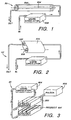
- FIG. 1 is a schematic view of an apparatus for the treatment of pumpable products such as air, water or liquid food products, such as fruit juices with pulses of intense incoherent pulsed light.
- the apparatus 50 comprises a reflective, cylindrical enclosure defining a treatment cavity (501), (also referred to as a treatment chamber or zone) through which the fluid flows and that surrounds a pulsed light source 504, which in the apparatus 50 shown may be a high intensity Xenon flashlamp provided with a suitable power source (not shown) in accordance with conventional practice for flashlamp operation.
- the reflective treatment cavity 501 serves to increase the effective energy density of the pulses of light that impinge upon the volume of pumpable products passing therethrough.
- a circulation pump 508 controls the flow rate of the pumpable product through the treatment cavity 501, which is coordinated with the pulse repetition rate of the flashlamps so that during the product's residence time within the treatment cavity 501, all of the product that passes therethrough receives a predetermined number of high-intensity, short-duration pulses of incoherent, polychromatic light in a broad spectrum.
- the product exiting the treatment cavity 501 will therefore be sterile or disinfected to the degree desired (as determined in accordance with the number of pulses of light and the energy density of the pulses of light throughout the treatment volume).
- the treatment cavity 501 is suitably arranged so as to be separated from the flashlamp 504 so as to prevent the product from contacting the flashlamp 504.
- the diameter of the treatment cavity 501 will vary depending upon many factors including but not limited to the specific light absorption characteristics of the product to be treated within the broad spectrum.
- the diameter of the treatment cavity 501 also varies as a function of the physical and operating characteristics of the flashlamps and the degree of product mixing expected between multiple pulses.
- the treatment cavity 501 preferably includes the metal reflector assembly 502 (also referred to as a reflector assembly) as its outer wall or as an external reflector, in order to reflect illumination traversing the product back inward toward the flashlamp.
- the metal reflector assembly 502 also referred to as a reflector assembly
- the desired minimum flux density preferably should be maintained throughout the treatment zone or alternatively mixing must occur to insure that all of the fluid is subjected to the appropriate minimum flux density and number of pulses.
- the flashlamp 556 is located internally of the treatment chamber 501 in the apparatus 50 (FIG. 1). one or more lamps may also or alternatively be located externally of the treatment chamber 501 in an alternate apparatus 521.
- An alternative design as shown in FIG. 2, in which the fluid, e.g., liquid food product, water, or air, to be treated is conducted through a transparent treatment conduit (e.g., a quartz glass tube) 552 that is positioned along one focus of an elliptical reflector 554.
- a flashlamp 556 is positioned along another focus of the elliptical reflector 554.
- Multiple elliptical segments (not shown), each having a lamp at one focus and the quartz tube 552 at the other focus, may be utilized if desired. In this manner, because the light emitted from the flashlamp 556 is focused toward the center of the treatment chamber, compensation is provided for the light absorption of the liquid being treated, so that all of the liquid is subjected to more uniform light treatment.
- the flashlamp 556 is jacketed in, e.g., a quartz sleeve or jacket for water or air cooling and optional spectral filtering (as can the flashlamp 504 in FIG. 1).
- an apparatus is shown of an intense incoherent light processing station 60 having a pulsed light source/reflector array 602 through which the product 601 passes, for example, in quartz tubing (not shown).
- the flashlamp/reflector array 602 is connected by umbilicals to an electrical pulse forming network 603 or pulser that energizes the flashlamp array either simultaneously or sequentially and a cooling/filtering circulation pump 604 that circulates liquid medium through a jacket assembly external to each lamp for cooling and/or spectral filtering by the use of selected solutions with the desired spectral transmittance/absorbance characteristics.
- the flashlamps are cooled using a quartz containing water jacket.
- the flashlamp/reflector array 602 comprises a plurality of lamps and reflectors that create intense, short-duration light pulses in a treatment region between upper and lower halves of the flashlamp/reflector array 602. While the illustrated processing station 60 uses straight lamps and reflector elements, other arrangements may be utilized. For example, flashlamps may be constructed in any shape in much the same way that neon lighting signs may also be made to any shape. Similarly, the reflector elements may be made of many different materials in many different geometries to accommodate imaging the flashlamp source upon the treated product with a desired energy density distribution. "The Optical Design of Reflectors", Second Edition, William B. Elmer, Published by John Wiley and Sons, Inc., New York is an appropriate resource as an introduction to the fundamentals of reflector design.
- FIG. 4 a cross-sectional view is shown of a water treatment cell 700 not itself in accordance with the present invention. Shown are an outer cylindrical housing 702, a cylindrical baffle 704, a first end plate 706 and a first lamp holder 708, a second end plate 710 and a second lamp holder 712, a water inlet 714, and first and second water outlets 716, 718. Located coaxially with the outer cylindrical housing 702 and cylindrical baffle 704 is a flashlamp 722 of the type described hereinabove.
- the outer cylindrical housing 702 along with the first and second end plates 706, 710 form a water-tight container into which water flows through the water inlet 714, and out of which water flows through the first and second water outlets 716, 718.
- Coaxial with the outer cylindrical housing 702 is the cylindrical baffle 704.
- the cylindrical baffle 704 is mounted to the second end plate 710 and terminates just short of the first end plate 706 such that water can flow from a region within the water-tight container outside the cylindrical baffle 704, around an end 720 of the cylindrical baffle 704 near the first end plate 706 and into a region within the cylindrical baffle 704.
- This arrangement provides for a fluid flow pattern that is as follows: water flows into the water-tight container through the water inlet 714 and into the region outside the cylindrical baffle 704; next the water flows past the cylindrical baffle 704 (to the left as oriented in FIG. 4) and around the end 720 of the cylindrical baffle 704; the water next flows within the cylindrical baffle 704 back toward the second end plate (toward the right as oriented in FIG. 4) and exits the cylindrical housing through the water outlets 716, 718.
- the above-described configuration provides for a substantially uniform eddy-free flow of water in the region within the cylindrical baffle 704. This is largely due to flow uniformities achieved when the water flows over the end 720 of the cylindrical baffle 704 into the region within the cylindrical baffle. As a result, uniform treatment with the high-intensity, short-duration pules of light in a broad spectrum is achieved.
- the creation of a uniform flow dynamic in the region within the cylindrical baffle 704 is further achieved by the use of an annular baffle 726 positioned between the cylindrical baffle 704 and the outer cylindrical housing 702 about 5 centimeters in from the inlet port 714. This annular baffle 726 helps to distribute the water flowing in through the inlet port 714 throughout the region between the cylindrical baffle 704 and the outer cylindrical housing 702.
- the water is exposed to high intensity, short-duration pulses of polychromatic light emitted from the flashlamp 722.
- the inner surface 724 of the cylindrical baffle 704 is reflectorized such that light emitted from the flashlamp 722 and passing through the water in the region within the cylindrical baffle 704 is reflected back toward the flashlamp 722. The reflected light is therefore passed back through the water, thereby increasing the effective energy density to which the water in the region within the cylindrical baffle 704 is exposed.
- This effective energy density is increased even further in view of the fact that the light is preferably reflected back and forth multiple times within the region within the cylindrical baffle 704 before being absorbed by microorganisms and other particles within the water, by the reflectorized inner surface of the cylindrical baffle 704, etc.
- the energy density to which the water within the cylindrical baffle is exposed is from between 0.01 J/cm 2 and 50 J/cm 2 , e.g., between 0.5 J/cm 2 and 1.5 J/cm 2 .
- the pulse duration of the high-intensity, short-duration pulses of polychromatic light is from between 0.001 ms and 100 ms, e.g.
- the pulse repetition rate is from between 1 Hz and 100 Hz for a cylindrical baffle having a length of from between 50 millimeters and 500 millimeters, e.g., 220 millimeters and a diameter from between 25 millimeters and 250 millimeters, e.g., 114 millimeters.
- the flashlamp emits at least 50% to 60%, e.g., 70% to 90% of its light at wavelengths of from between 170 nm and 2600 nm.
- At least from between 1% and 1%, e.g., 10% of the energy density of the light emitted from the flashlamp is concentrated at wavelengths of from between 200 nanometers and 320 nanometers, e.g., 260 nanometers.
- FIG. 5 a cross-sectional view is shown of a water treatment system (or cell) 700 made in accordance with an embodiment of the present invention. Shown are the outer cylindrical housing 702, the first and second end plates 706, 710 and lamp holders 708, 712, the water inlet 714, the first and second water outlets 716, 718, the cylindrical baffle 704, the flashlamp 722, and a quartz jacket 725.
- FIG. 5 is substantially the same as the apparatus of FIG. 4.
- the quartz jacket 725 provides a water-tight barrier that separates space within the cylindrical baffle 704 from a space immediately proximate to the flashlamp 722.
- This arrangement allows air or cooling water to be circulated within the space immediately proximate to the flashlamp 722 for the purpose of cooling the flashlamp 722 or for spectrally filtering the light emitted from the flashlamp 722.
- the embodiment of FIG. 5 may provide for longer flashlamp life, a more desirable frequency spectra, and/or a shortened pulse repetition rate (due to increased flashlamp cooling between flashes) than possible in the apparatus of FIG. 4.
- FIG. 6 a cross-sectional view is shown of a water treatment system 700. Shown are the outer cylindrical housing 702, the first and second end plates 706, 710 and lamp holders 708, 712, the water inlet 714, the cylindrical baffle 704, the flashlamp 722, and a annular baffle 726.
- FIG. 6 is substantially the same as the embodiment of FIG. 5.
- the first and second water outlets 716, 718, of FIG. 4 are replaced in the embodiment of FIG. 6 with a single frustoconical outlet 902 that passes through the side of the cylindrical baffle 704 thereby permitting light from the flashlamp 722 to irradiate the interior of the frustoconical outlet 902.
- a recirculating hose 904 receives water from the frustoconical outlet 902 when decontaminated water or air is not needed, and recycles such water through the water treatment system 900. When the recirculating hose 904 is removed, decontaminated water flows through the frustoconical outlet and can be utilized as needed.
- This arrangement is particularly suited for laboratory use where water is withdrawn from the water treatment system 700 periodically, and contamination of the water after it exits the water treatment system 900 is of particular concern. Numerous uses of the present embodiment are however contemplated.
- FIG. 7 a perspective view is shown of an air treatment system 800 not in accordance with the present invention. Shown are a treatment region 802 of an air duct 804, including a reflective inner surface 806, a transversely oriented flashlamp 808, a baffled exit region 810 of the air duct 804 and an exhaust duct 812.
- air is flowed into the treatment region 802 of the air duct 804, as a result of a vacuum pressure created by a fan (not shown) in the exhaust duct 812.
- the air is flowed within the treatment region 802 of the air duct 804 past the flashlamp 808.
- the air is exposed to one or more high-intensity, short-duration pulses of polychromatic light in a broad spectrum, which are emitted from the flashlamp 808.
- the effective energy density to which such air is exposed during its residency within the treatment region 802 is dramatically increased by the presence of a reflectorized interior surface of the treatment region 802, which causes light emitted from the flashlamp 808, and passing through air within the treatment region, to be reflected back into the air within the treatment region.
- the exit region 810 contains, for example, three baffles 814 that separate the exit region 810 into four distinct airways.
- the baffles 814 help to assure uniform air flow as the air exits the air duct 804, and more importantly, serve to prevent light emitted from the flashlamp 808 from exiting the treatment region 802.
- an interior surface of each of the four distinct airways is painted flat black.
- an entrance region through which the air flows before reaching the treatment region 802 may also contain baffles like those in the exit region 810, and such baffles can be painted flat black.
- the baffles at the entrance region also, like the baffles at the exit region 810, prevent light emitted from the flashlamp 808 from exiting the treatment region.
- treated air After exiting the air duct 804 through the exit region 810, treated air is sucked into the exhaust duct 812 where it is directed to a space in which sterile air is desired.
- the exhaust duct 812 is suitably connected to the air duct 804 so as to prevent untreated air from entering the exhaust duct 812.
- each original (1000 microliters) suspension is recovered and transferred to fresh vials (labeled, siliconized microfuge tubes).
- Each oocyst preparation is condensed by centrifugation to approximately 200 microliters and administered to neonatal mice in 25 microliter volumes. After approximately one week (61 ⁇ 2 days) the mice are euthanized by carbon dioxide inhalation.
- a terminal colon (approximately 1 cm) is removed from each neonatal mouse and placed in a microfuge tube containing 400 microliters of 2.5% potassium dichromate (w/v in deionized water).
- a remaining portion of the intestinal tract is removed from each of the neonatal mice and pooled with the intestinal tracts from the other neonatal mice within respective treatment groups (according to the number of flashes of light administered to each sample).
- the terminal colon samples are vortexed vigorously and the supernatants are processed over discontinuous sucrose gradients to recover and isolate oocysts.
- the samples are incubated with a Cryptosporidium oocyst specific monoclonal antibody conjugated with fluorescein isothiocyanate (OW 50-FITC) and is analyzed by flow cytometry.
- OW 50-FITC Cryptosporidium oocyst specific monoclonal antibody conjugated with fluorescein isothiocyanate
- Logical gating identifies the oocysts that are enumerated in 100 microliters of each sample suspension. This volume represents approximately 1/12 of the original sample volume.
- the raw data (number of events in the logical gate representing oocysts) for each sample along with example flow cytometry plots for positive and negative samples are included in the APPENDIX, on pages 3-4 and 1-2 respectively.
- the pooled intestines from each group are homogenized in potassium dichromate and the homogenate is evaluated in a manner similar to that described above for the terminal colon segments.
- the purpose of the pooled intestine assay is to attempt to detect low numbers of oocysts in the pooled samples that may have been missed in individual terminal colon samples. The oocyst numbers are presented for these samples in the APPENDIX on page 6.
- mice inoculated with oocysts that received any tested level of treatment of pulsed, high-intensity, broadband, polychromatic light mice inoculated with oocysts that received any tested level of treatment of pulsed, high-intensity, broadband, polychromatic light, while mice receiving control oocysts exhibited large numbers of oocysts in their intestinal samples.
- a number of flashes are emitted from the flashlamp at a pulse duration of 300 microseconds and a pulse repetition rate of 1 flash per second.
- the Cryptosporidium-oocyst-containing solution is then withdrawn from between the quartz disks using a sterile pipettor and is placed in a sterile labeled vial.
- Control suspensions were also prepared by transferring the Cryptosporidium-oocyst-containing solution to the quartz disks, and then moving them into the vial without treatment using pulsed light.
- control suspensions are prepared for dilution yielding 10 6 , 10 5 , and 10 4 Cryptosporidium parvum oocysts per milliliter, e.g, a 50 microliter aliquot of the control suspension is diluted in 450 microliters tissue culture grade phosphate buffered solution (T-PBS) yielding a 1/10 dilution.
- T-PBS tissue culture grade phosphate buffered solution
- Control and treated Cryptosporidium parvum oocyst suspensions are titrated to suspend oocysts and are dispensed into four-day cultures of Maden-Darby Canine Kidney (MDCK) cells (in Ultraculture).
- MDCK Maden-Darby Canine Kidney
- Each oocyst suspension is dispensed in a 100 microliter volume in duplicate chambers (two per treatment). Remaining oocyst suspensions are stored at 4° centigrade. The four-day cultures are incubated at 37° centigrade (5% CO 2 ). Each chamber is washed at three hours PI with T-PBS and fresh culture medium is replaced. Fresh culture medium is again replaced at 24 hours PI. At 48 hours PI chambers are washed with T-PBS three times and fixed with Bouings solution for approximately one hour (2.0 milliliters per chamber well).
- the Bouings solution is decolorized by five successive washings with 70% ethanol over the course of one hour.
- the chambers are washed with T-PBS and the T-PBS is replaced with phosphate buffered solution/bovine serum albumin (PBS/BSA) and incubated for 30 minutes.
- PBS/BSA phosphate buffered solution/bovine serum albumin
- the PBS/BSA is replaced with fluorochrome-labeled monoclonal antibodies solution (C3C3-CyC, 1/500th dilution, 300 microliter per chamber).
- the chambers are then incubated for 90 minutes at room temperature in the dark on a rocker platform.
- the chambers are then washed three times with T-PBS.
- the T-PBS is aspirated and two drops of polyvinyl alcohol/anti-quenching agent (PVA II/DABCO) (the anti-quenching agent is 1,4-diazabicyclo-[2.2.2] octane from Sigma Chemical Company) is added to each chamber. Cover slips (18 square millimeters) are mounted taking care not to trap air bubbles therebeneath. Excess T-PBS or PCA II/DABCO is aspirated. Parasite development is then scored microscopically for each dilution and disinfectant treatment.
- PVA II/DABCO polyvinyl alcohol/anti-quenching agent
- control and treated oocyst preparations are titrated and dispensed into microcentrifuge tubes (100 microliters per tube). An equal volume of DMEM base medium supplemented with 1.5% NaT is added and the tubes are incubated at 37° centigrade for 45 minutes. Excystation is accessed by preparing wet mounts and scanning the slides for free sporozytes and empty and partially empty oocyst walls.
- An experimental apparatus is constructed similar in structure to the apparatus shown in FIG. 7 with the addition of an ultrasonic sprayer that introduces a Bacillus pumilus spore-containing spray into the air as it passes into the air duct, and with the addition of a collection plate positioned between the air duct and the exhaust duct for collecting the Bacillus pumilus spores after treatment.
- the flashlamp is flashed at a pulse repetition rate of about 2.5 or about 5.0 flashes per second. About one second after the flashing of the flashlamp is commenced, the ultrasonic sprayer sprays 180 microliters (or 160 microliters in the case of the 5.0 flash per second pulse repetition rate) of spores into the air passing into the duct. After the spraying of the spores, the flashlamp is flashed for an additional 20 seconds insuring that the air duct is free of spores before ceasing flashing of the flashlamp.
- the air which has a central line velocity of 0.5 meters per second, carries the spores through the treatment region past the flashlamp and into the exit region. Upon exiting the air duct, the spores are carried onto the collection plate located between the air duct and the exhaust duct.
- Lab jacks are initially set up for a 0.8 Joules/cm 2 fluence level (which results from a 120 millimeter distance between a quartz window and a flashlamp light source to a bottom quartz disc.
- a vial of Poliovirus is vigorously shaken.
- a 150 microliter sample of the Poliovirus are transferred from the vial to a 1 millimeter space between a pair of quartz discs.
- the pair of discs is gently tilted until the 150 microliter sample is positioned near the center of the discs.
- the discs are then placed on the lab jack.
- the discs are removed from the lab jack and the 150 microliter sample is withdrawn and placed in a sterile vial.
- two flashes at 0.8 Joules/cm 2 are delivered to the 150 microliter sample. Further samples are treated with two flashes at 0.6 Joules/cm 2 , 0.4 Joules/cm 2 and 0.2 Joules/cm 2 , by adjusting the lab jacks. The treated samples are respectively withdrawn and placed in sterile vials. The Polio virus suspensions are then quantitated using tissue culture plaque titer assays.
Description
| In vitro growth | |||||
| Treatment (Joules) | Oocysts per Chamber | 1 Flash | 2 Flash | ||
| 0.11 | 106 | <1+ | <1+ | - | - |
| 0.22 | 106 | - | - | - | - |
| 0.44 | 106 | - | - | - | - |
| 0.67 | 105 | - | - | - | - |
| 0.89 | 104 | - | - | - | - |
| 1.11 | 106 | - | - | - | - |
| Control | 106 | >4+ | >4+ | NA | NA |
| Control | 105 | 3-4+ | 3-4+ | NA | NA |
| Control | 104 | 2-3+ | 2-3+ | NA | NA |
| Control | 103 | 1-2+ | 1-2+ | NA | NA |
| Excystation (with sporozites) | |||
| Treatment (joules) | Oocysts per Chamber | 1 Flash | 2 Flash |
| 0.11 | 106 | 2+ | 2+ |
| 0.22 | 106 | 1+ | 1+ |
| 0.44 | 106 | - | - |
| 0.67 | 106 | - | - |
| 0.89 | 106 | - | - |
| 1.11 | 106 | - | - |
| Control | 106 | 4+ | NA |
| Control (mean + std. dev.) | Flashing Control (mean + std. dev.) | Sample (mean + std. dev.) | |
| 2.5 Hz | 112.5 ± 39 log 2.05 (+ 2.18/-1.86) | 126 ± 103 log 2.1 (+2.36/-1.36) | 0.0 ± 0 |
| 5.0 Hz | 123.1 ± 48 log 2.09 (+2.23/-1.87) | 114 ± 48 log 2.05 (+2.2/-1 82) | 0.0 ± 0 |
| Sample | Titer (plaque forming units/ml) |
| 0.8 J/cm2 | 2.3 x 10² |
| 0.6 J/cm2 | 85 |
| 0.4 J/cm2 | 2.2 x 10⁴ |
| 0.2 J/cm2 | 1.6 x 10³ |
| Control (non-treated) | 9 x 10⁸ |


| APPENDIX - 3 | ||||
| RAW DATA (P. 1 OF 2) NO. OF EVENTS IN THE LOGICAL GATE REPRESENTING CRYPTOSPORIDIUM PARVUM OOCYSTS (NOT POOLED) | ||||
| BALB/c mouse fecal oocyst quantitation by flow cytometry (PureBright) | ||||
| Treatment | #/mL | Dose | Mouse ID | Wk-1 |
| HIGH | 10^7 | 10^6 | H7-1 | 9 |
| HIGH | 10^7 | 10^6 | H7-2 | 1 |
| HIGH | 10^7 | 10^6 | H7-3 | 4 |
| HIGH | 10^7 | 10^6 | H7-4 | 3 |
| HIGH | 10^7 | 10^6 | H7-5 | 3 |
| MEDIUM | 10^7 | 10^6 | M7-1 | 2 |
| MEDIUM | 10^7 | 10^6 | M7-2 | 1 |
| MEDIUM | 10^7 | 10^6 | M7-3 | 5 |
| MEDIUM | 10^7 | 10^6 | M7-4 | 3 |
| MEDIUM | 10^7 | 10^6 | M7-5 | 2 |
| MEDIUM | 10^7 | 10^6 | M7-6 | 2 |
| MEDIUM | 10^7 | 10^6 | M7-7 | 5 |
| LOW | 10^7 | 10^6 | L7-1 | 1 |
| LOW | 10^7 | 10^6 | L7-2 | 7 |
| LOW | 10^7 | 10^6 | L7-3 | 10 |
| LOW | 10^7 | 10^6 | L7-4 | 2 |
| CONTROL | 10^7 | 10^6 | C7-1 | 1411 |
| CONTROL | 10^7 | 10^6 | C7-2 | 34 |
| CONTROL | 10^7 | 10^6 | C7-3 | 2325 |
| CONTROL | 10^7 | 10^6 | C7-4 | 1209 |
| CONTROL | 10^7 | 10^6 | C7-5 | 963 |
| HIGH | 10^6 | 10^5 | H6-1 | 3 |
| HIGH | 10^6 | 10^5 | H6-2 | 1 |
| HIGH | 10^6 | 10^5 | H6-3 | 2 |
| HIGH | 10^6 | 10^5 | H6-4 | 2 |
| MEDIUM | 10^6 | 10^5 | M6-1 | 4 |
| MEDIUM | 10^6 | 10^5 | M6-2 | 1 |
| MEDIUM | 10^6 | 10^5 | M6-3 | 4 |
| MEDIUM | 10^6 | 10^5 | M6-4 | 3 |
| LOW | 10^6 | 10^5 | L6-1 | 5 |
| LOW | 10^6 | 10^5 | L6-2 | 6 |
| LOW | 10^6 | 10^5 | L6-3 | 1 |
| LOW | 10^6 | 10^5 | L6-4 | 0 |
| CONTROL | 10^6 | 10^5 | C6-1 | 239 |
| CONTROL | 10^6 | 10^5 | C6-2 | 1621 |
| CONTROL | 10^6 | 10^5 | C6-3 | 2270 |
| CONTROL | 10^6 | 10^5 | C6-4 | 4344 |
| APPENDIX - 4 | ||||
| RAW DATA (P. 2 OF 2) NO. OF EVENTS IN THE LOGICAL GATE REPRESENTING CRYPTOSPORIDIUM PARVUM OOCYSTS (NOT POOLED) | ||||
| UNINFECTED | 0 | 0 | U1-1 | 0 |
| UNINFECTED | 0 | 0 | U1-1 | 4 |
| Control (calf 8IA10) | 8052 | |||
| Note: values <=10 are considered background | ||||
| Mean # oocysts/100 µl suspension | ||||
| HIGH | MEDIUM | LOW | CONTROL | |
| 10^7 | 4 | 2.9 | 5 | 1188.4 |
| 10^6 | 2 | 3 | 3 | 2118.5 |
| UNINFECTED | 2 |

| APPENDIX 6 | |||||
| RAW DATA (P. 1 OF 1) NO. OF EVENTS IN THE LOGICAL GATE REPRESENTING CRYPTOSPORIDIUM PARVUM OOCYSTS (POOLED SAMPLE) | |||||
| BALB/c mouse fecal oocyst quantitation by flow cytometry (PureBright) | |||||
| K2Cr2O7 | |||||
| Treatment | #/mL | Dose | # intestines | Volume | Wk-1 |
| HIGH | 10^7 | 10^6 | 5 | 20 ml | 9 |
| MEDIUM | 10^7 | 10^6 | 7 | 20 ml | 10 |
| LOW | 10^7 | 10^6 | 4 | 20 ml | 10 |
| CONTROL | 10^7 | 10^6 | 5 | 20 ml | 510 |
| HIGH | 10^6 | 10^5 | 4 | 20 ml | 14 |
| MEDIUM | 10^6 | 10^5 | 4 | 20 ml | 24 |
| LOW | 10^6 | 10^5 | 4 | 20 ml | 11 |
| CONTROL | 10^6 | 10^5 | 4 | 20 ml | 441 |
| UNINFECTED | 0 | 0 | 2 | 20 ml | 8 |
| Pooled intestines were homogenized in 20 ml K2Cr2O7 | |||||
| VirTis VirTishear setting 70, 40 sec | |||||
| 1 ml fraction collected and stored at 4 C | |||||
| 200 microliters processed over gradient, washed, labeled with Mab | |||||
| and analyzed on flow cytometer | |||||
| Note: values <=25 are considered background | |||||
| (this set was a little noisier than the set above) |
Claims (13)
- A system for deactivating microorganisms in fluid comprising:a fluid-tight housing (702) having an inlet port (714) and an outlet port (716); anda tubular light source (722) for emitting at least one short-duration, high intensity pulse of broad spectrum polychromatic light positioned within the fluid-tight housing; characterized by:a tubular baffle (704) positioned within the fluid-tight housing for directing a substantially uniform eddy-free flow of fluid in a direction substantially parallel to the light source;a jacket (725) surrounding the tubular light source to provide a fluid-tight barrier therearound; andmeans for circulating a cooling material between the jacket and the tubular light source within the fluid-tight barrier for cooling the tubular light source.
- The system of claim 1, wherein:said tubular baffle (704) has a first and a second end; andsaid inlet port (714) and said outlet port (716) are positioned proximate the second end of the tubular baffle.
- The system of claim 1 or 2, wherein:said tubular baffle (704) is arranged to direct said fluid from said inlet port (714) in a direction substantially antiparallel to said light source (722), and is arranged to direct said fluid to said outlet port (716) in a direction substantially parallel to said light source.
- The system of any preceding claim, wherein:said inlet port (714) is positioned to flow fluid into said fluid-tight housing (702) from outside said tubular baffle (704); andsaid outlet port (716) is positioned to withdraw water from said fluid-tight housing (702) from inside said tubular baffle (704), said fluid flowing around said first end of said tubular baffle.
- The system of any preceding claim, wherein:said light source (722) is positioned substantially along a central axis of said tubular baffle (704).
- The system of any preceding claim, wherein:said tubular baffle (704) is substantially cylindrical.
- The system of any preceding claim, wherein:said fluid-tight housing (702) is substantially cylindrical.
- The system of any preceding claim, wherein:an inner surface of the tubular baffle (704) is reflectorized for reflecting light emitted from the tubular light source (722).
- The system of any preceding claim further comprising:an annular baffle (726) located near the inlet port (714) whereby the annular baffle helps distribute the fluid flowing through the inlet port.
- The system of any preceding claim, wherein:the cooling material is such as to spectrally filter light from the tubular light source (722).
- The system of any preceding claim, wherein:said tubular baffle (704) comprises a cylindrical baffle positioned within said fluid-tight housing (702) which is cylindrical with a first region formed between the cylindrical baffle and the cylindrical fluid-tight housing for fluid to flow in a first flow direction;said cylindrical baffle (704) has a closed second end attached to a second end of the cylindrical fluid-tight housing (702) and an open first end terminating before a first closed end of the cylindrical fluid-tight housing forming a gap therebetween;said tubular light source (722) is positioned within the cylindrical baffle (704) with a second region formed between the tubular light source and the cylindrical baffle for fluid to flow in a second flow direction;said inlet port (714) is located proximate the second end of the cylindrical baffle (704), whereby said fluids enter the system through the said inlet port travelling in the first flow direction between the cylindrical fluid-tight housing and the cylindrical baffle, around the gap at the first end of the cylindrical baffle and travelling opposite in the second flow direction between the cylindrical baffle and the tubular light source to the outlet port wherein the fluid exits the system.
- The system of any preceding claim, wherein said outlet port (716) is located in the second end of the cylindrical fluid-tight housing (702) between the cylindrical baffle (704) and the tubular light source (722).
- The system of claim 11 or 12, as appended to claim 11, wherein:said cylindrical baffle (704) is coaxial with the cylindrical fluid-tight housing (702); andsaid tubular light source (722) is coaxial with the cylindrical baffle.
Applications Claiming Priority (3)
| Application Number | Priority Date | Filing Date | Title |
|---|---|---|---|
| US54845395A | 1995-10-26 | 1995-10-26 | |
| US548453 | 1995-10-26 | ||
| PCT/US1996/016437 WO1997015332A1 (en) | 1995-10-26 | 1996-10-16 | Improved deactivation of organisms using high-intensity pulsed polychromatic light |
Publications (2)
| Publication Number | Publication Date |
|---|---|
| EP0873143A1 EP0873143A1 (en) | 1998-10-28 |
| EP0873143B1 true EP0873143B1 (en) | 2003-02-19 |
Family
ID=24188898
Family Applications (1)
| Application Number | Title | Priority Date | Filing Date |
|---|---|---|---|
| EP96936466A Expired - Lifetime EP0873143B1 (en) | 1995-10-26 | 1996-10-16 | Improved deactivation of organisms using high-intensity pulsed polychromatic light |
Country Status (10)
| Country | Link |
|---|---|
| US (3) | US5900211A (en) |
| EP (1) | EP0873143B1 (en) |
| JP (1) | JPH11514277A (en) |
| KR (1) | KR19990067075A (en) |
| AU (1) | AU7430296A (en) |
| BR (1) | BR9611189A (en) |
| CA (1) | CA2235244C (en) |
| DE (1) | DE69626313T2 (en) |
| TW (1) | TW357088B (en) |
| WO (1) | WO1997015332A1 (en) |
Families Citing this family (107)
| Publication number | Priority date | Publication date | Assignee | Title |
|---|---|---|---|---|
| DE69626313T2 (en) * | 1995-10-26 | 2003-11-27 | Purepulse Technologies Inc | DISABLING ORGANIC WITH POLYCHROMATIC HIGH INTENSITY PULSE LIGHT |
| US6433344B1 (en) | 1996-05-22 | 2002-08-13 | Purepulse Technologies, Inc. | Pulsed light sterilization of drinking water and drinking water containers |
| US7038219B2 (en) * | 1996-05-22 | 2006-05-02 | Purepulse Technologies, Inc. | Sterilization of packages and their contents using light |
| AU3364797A (en) * | 1997-06-23 | 1998-10-20 | Kamurov, Alexandr Semenovich | Method and device for uv treatment of liquid, air and surface |
| ES2262237T3 (en) * | 1997-07-09 | 2006-11-16 | Futureenergy, Corp. | METHOD AND APPLIANCE FOR HEAT GENERATION. |
| US6117335A (en) * | 1998-02-23 | 2000-09-12 | New Star Lasers, Inc. | Decontamination of water by photolytic oxidation/reduction utilizing near blackbody radiation |
| US6129893A (en) * | 1998-05-13 | 2000-10-10 | Calgon Carbon Corporation | Method for preventing replication in Cryptosporidium parvum using ultraviolet light |
| US6565803B1 (en) * | 1998-05-13 | 2003-05-20 | Calgon Carbon Corporation | Method for the inactivation of cryptosporidium parvum using ultraviolet light |
| DE19823011C2 (en) * | 1998-05-22 | 2000-12-28 | Hansa Metallwerke Ag | Device for sterilizing water that flows through a sanitary facility |
| US6030653A (en) * | 1998-11-03 | 2000-02-29 | Rosenthal; Richard A. | Inactivation of iron dependent bacterium using visible and near infrared light |
| JP2002528846A (en) * | 1998-11-04 | 2002-09-03 | ゼノン・コーポレーション | Spiral lamp for UV curing of coatings and joining digital versatile discs (DVD) or compact discs (CD) |
| US6692694B1 (en) | 1998-11-09 | 2004-02-17 | Clean Earth Technologies, Llc | Method and apparatus for photosensitized ultraviolet decontamination of surfaces and aerosol clouds |
| US6592816B1 (en) | 1999-03-01 | 2003-07-15 | Johnson & Johnson Vision Care, Inc. | Sterilization system |
| US7879288B2 (en) | 1999-03-01 | 2011-02-01 | Johnson & Johnson Vision Care, Inc. | Method and apparatus of sterilization using monochromatic UV radiation source |
| US6465799B1 (en) | 1999-03-01 | 2002-10-15 | Johnson & Johnson Vision Care, Inc. | UV radiation system having materials for selectively attenuating radiation |
| IL129564A (en) * | 1999-04-23 | 2004-06-20 | Atlantium Lasers Ltd | Method for disinfecting and purifying liquids and gases and a device to use therein |
| AU2004210604A1 (en) * | 1999-04-27 | 2004-11-04 | Calgon Carbon Corporation | Method for the inactivation of cryptosporidium parvum and giardia cysts using ultraviolet light |
| US6219584B1 (en) * | 1999-07-09 | 2001-04-17 | Therakos, Inc. | Method and system for determining an effective amount of light energy to delivery to fluids having targets for the light energy |
| JP2001118818A (en) * | 1999-08-12 | 2001-04-27 | Uct Kk | Ultraviolet ray-treating device and method |
| SE515317C2 (en) * | 1999-10-14 | 2001-07-16 | Josab Internat Ab | Apparatus and method for purifying water from microorganisms |
| US6264836B1 (en) | 1999-10-21 | 2001-07-24 | Robert M. Lantis | Method and apparatus for decontaminating fluids using ultraviolet radiation |
| MY120639A (en) * | 2000-01-21 | 2005-11-30 | Lightstream Technologies Inc | Method and apparatus for decontaminating fluids using ultraviolet radiation |
| US6312931B1 (en) | 2000-02-11 | 2001-11-06 | Purepulse Technologies, Inc. | Protecting molecules in biologically derived compositions while treating with high intensity broad-spectrum pulsed light |
| US6331321B1 (en) * | 2000-04-25 | 2001-12-18 | John A. Robbins | Process and apparatus for reduction of microorganisms in a conductive medium using low voltage pulsed electrical energy |
| US6730923B1 (en) * | 2000-05-05 | 2004-05-04 | Purepulse Technologies, Inc. | Transmissive conveyor for use in pulsed light sterilization |
| CA2409993A1 (en) * | 2000-05-26 | 2001-12-06 | Purepulse Technologies, Inc. | Pulsed polychromatic light passthrough sterilization device |
| US6843961B2 (en) * | 2000-06-15 | 2005-01-18 | Gambro, Inc. | Reduction of contaminants in blood and blood products using photosensitizers and peak wavelengths of light |
| US9044523B2 (en) | 2000-06-15 | 2015-06-02 | Terumo Bct, Inc. | Reduction of contaminants in blood and blood products using photosensitizers and peak wavelengths of light |
| US20020176796A1 (en) * | 2000-06-20 | 2002-11-28 | Purepulse Technologies, Inc. | Inactivation of microbes in biological fluids |
| WO2001097868A1 (en) * | 2000-06-20 | 2001-12-27 | Purepulse Technologies, Inc. | The inactivation of nucleic acids using broad-spectrum pulsed light |
| US20020134734A1 (en) * | 2000-08-28 | 2002-09-26 | Ocean Power Corporation | Method for pretreating water for desalination |
| JP3825993B2 (en) * | 2000-11-16 | 2006-09-27 | キヤノン株式会社 | Pollutant decomposition method and apparatus |
| US20030030011A1 (en) * | 2001-05-17 | 2003-02-13 | Purepulse Technologies, Inc. | Light treatment control in a fluid treatment system using light for the treatment of fluid products |
| US20030060747A1 (en) * | 2001-05-17 | 2003-03-27 | Fries William M. | Fluid flow path for a fluid treatment system using light for the decontamination of fluid products |
| WO2003047684A2 (en) * | 2001-12-04 | 2003-06-12 | University Of Southern California | Method for intracellular modifications within living cells using pulsed electric fields |
| US6960201B2 (en) * | 2002-02-11 | 2005-11-01 | Quanticum, Llc | Method for the prevention and treatment of skin and nail infections |
| US7494502B2 (en) * | 2002-02-11 | 2009-02-24 | Keraderm, Llc | Alteration of the skin and nail for the prevention and treatment of skin and nail infections |
| US20040005694A1 (en) * | 2002-05-08 | 2004-01-08 | Herbert Lutz | Light decontamination of fermentation media |
| AU2003242865A1 (en) * | 2002-07-03 | 2004-01-23 | Athanasios Nikolaou | Method for the treatment of the organic and/or the inorganic matter for the modifying its physicochemical properties |
| GR20020100319A (en) * | 2002-07-03 | 2004-03-19 | Νικολαουααθανασιοσαπαναγιωτη | Method of treating organic and/or inorganic matter for the useful modification of the physicochemical properties thereof |
| EP1575669B1 (en) * | 2002-08-09 | 2010-10-27 | Primos OÜ | A laser device for treatment of infections |
| US7682641B1 (en) * | 2003-06-11 | 2010-03-23 | 6231934 Canada Inc. | Method and apparatus for preserving perishable products |
| US6951617B2 (en) * | 2003-09-16 | 2005-10-04 | Purepise Technologies, Inc. | Method and apparatus for controlling flow profile to match lamp fluence profile |
| US7781947B2 (en) * | 2004-02-12 | 2010-08-24 | Mattson Technology Canada, Inc. | Apparatus and methods for producing electromagnetic radiation |
| EP2913722A1 (en) | 2004-11-24 | 2015-09-02 | NovaCentrix Corp. | Electrical, plating and catalytic uses of metal nanomaterial compositions |
| DE102004057076A1 (en) * | 2004-11-25 | 2006-06-22 | Wedeco Ag | Vorkammerreaktor |
| US7255789B2 (en) * | 2004-12-13 | 2007-08-14 | Fite Jr Robert D | Method and apparatus for liquid purification |
| US7783383B2 (en) * | 2004-12-22 | 2010-08-24 | Intelligent Hospital Systems Ltd. | Automated pharmacy admixture system (APAS) |
| JP2008525125A (en) * | 2004-12-22 | 2008-07-17 | インテリジェント ホスピタル システムズ リミテッド | Automatic dispensing system (APAS) |
| US20060216193A1 (en) * | 2005-03-22 | 2006-09-28 | Johnson Kaj A | Cleaning tools with UV flash unit |
| US7626187B2 (en) * | 2005-06-02 | 2009-12-01 | George Younts | Method and apparatus for eradicating undesirable elements that cause disease, ailments or discomfort |
| US7511281B2 (en) | 2005-08-31 | 2009-03-31 | Ultraviolet Sciences, Inc. | Ultraviolet light treatment chamber |
| US9511344B2 (en) * | 2007-12-18 | 2016-12-06 | Ultraviolet Sciences, Inc. | Ultraviolet light treatment chamber |
| US9808544B2 (en) * | 2005-08-31 | 2017-11-07 | Ultraviolet Sciences, Inc. | Ultraviolet light treatment chamber |
| US7931859B2 (en) * | 2005-12-22 | 2011-04-26 | Intelligent Hospital Systems Ltd. | Ultraviolet sanitization in pharmacy environments |
| US20070205724A1 (en) * | 2006-03-03 | 2007-09-06 | Schaefer Raymond B | Advanced surface discharge lamp systems |
| US20070248487A1 (en) * | 2006-03-27 | 2007-10-25 | Kay Robert E | Systems and processes for disinfecting liquids |
| WO2007123859A2 (en) * | 2006-04-17 | 2007-11-01 | Keraderm Llc | Method and device to inactivate and kill cells and organisms that are undesirable |
| US7593289B2 (en) * | 2006-04-17 | 2009-09-22 | Phoenix Science & Technology, Inc. | Reflectors and reflector light and sound source systems |
| US8834788B2 (en) * | 2006-05-04 | 2014-09-16 | Fogg Filler Company | Method for sanitizing/sterilizing a container/enclosure via controlled exposure to electromagnetic radiation |
| CN101600410B (en) * | 2006-11-09 | 2013-12-04 | 智能医院体系有限公司 | Control of fluid transfer operations |
| WO2008106576A1 (en) * | 2007-02-28 | 2008-09-04 | Keraderm Llc | Phototherapy treatment and device to improve the appearance of nails and skin |
| TW200847599A (en) * | 2007-05-29 | 2008-12-01 | Novatek Microelectronics Corp | Voltage regulator and voltage regulating method thereof and voltage producer with voltage regulator disclosed by the present invention |
| US8764702B2 (en) * | 2007-07-05 | 2014-07-01 | Baxter International Inc. | Dialysis system having dual patient line connection and prime |
| US8157761B2 (en) | 2007-07-05 | 2012-04-17 | Baxter International Inc. | Peritoneal dialysis patient connection system |
| US7736328B2 (en) * | 2007-07-05 | 2010-06-15 | Baxter International Inc. | Dialysis system having supply container autoconnection |
| US8496609B2 (en) | 2007-07-05 | 2013-07-30 | Baxter International Inc. | Fluid delivery system with spiked cassette |
| US7955295B2 (en) | 2007-07-05 | 2011-06-07 | Baxter International Inc. | Fluid delivery system with autoconnect features |
| US8197087B2 (en) | 2007-07-05 | 2012-06-12 | Baxter International Inc. | Peritoneal dialysis patient connection system using ultraviolet light emitting diodes |
| FR2919857B1 (en) * | 2007-08-06 | 2011-06-17 | Claranor | APPARATUS FOR TREATING LIQUIDS BY PULSE RADIATION |
| US8271138B2 (en) * | 2007-09-12 | 2012-09-18 | Intelligent Hospital Systems Ltd. | Gripper device |
| US8225824B2 (en) | 2007-11-16 | 2012-07-24 | Intelligent Hospital Systems, Ltd. | Method and apparatus for automated fluid transfer operations |
| FR2927507B1 (en) * | 2008-02-19 | 2016-11-25 | Jacquet Panification | PROCESS FOR MANUFACTURING DECONTAMINE BAKERY PRODUCTS, DECONTAMINE BAKERY PRODUCTS AND DEVICE FOR CARRYING OUT SAID METHOD. |
| US9044544B2 (en) * | 2008-11-21 | 2015-06-02 | Baxter International Inc. | Dialysis machine having auto-connection system with roller occluder |
| US8386070B2 (en) * | 2009-03-18 | 2013-02-26 | Intelligent Hospital Systems, Ltd | Automated pharmacy admixture system |
| US8747764B1 (en) | 2009-03-27 | 2014-06-10 | Dartmouth-Hitchcock Clinic | Inline intravenous fluid sterilizer |
| US20120156669A1 (en) | 2010-05-20 | 2012-06-21 | Pond Biofuels Inc. | Biomass Production |
| US11512278B2 (en) | 2010-05-20 | 2022-11-29 | Pond Technologies Inc. | Biomass production |
| US8969067B2 (en) | 2010-05-20 | 2015-03-03 | Pond Biofuels Inc. | Process for growing biomass by modulating supply of gas to reaction zone |
| US8940520B2 (en) | 2010-05-20 | 2015-01-27 | Pond Biofuels Inc. | Process for growing biomass by modulating inputs to reaction zone based on changes to exhaust supply |
| US8889400B2 (en) | 2010-05-20 | 2014-11-18 | Pond Biofuels Inc. | Diluting exhaust gas being supplied to bioreactor |
| JP2011014541A (en) * | 2010-07-09 | 2011-01-20 | Mattson Technology Canada Inc | Device and method for generating highly intense electromagnetic radiation |
| EP2614300B1 (en) * | 2010-09-10 | 2016-12-28 | Trojan Technologies | Radiation source assembly |
| US8466434B2 (en) | 2010-11-02 | 2013-06-18 | Goodrich Corporation | Aircraft potable water system |
| US20120276633A1 (en) | 2011-04-27 | 2012-11-01 | Pond Biofuels Inc. | Supplying treated exhaust gases for effecting growth of phototrophic biomass |
| US9093258B2 (en) | 2011-06-08 | 2015-07-28 | Xenex Disinfection Services, Llc | Ultraviolet discharge lamp apparatuses having optical filters which attenuate visible light |
| GB2495481A (en) * | 2011-10-05 | 2013-04-17 | Microtek Processes Ltd | Treatment device for liquid products |
| US9295742B2 (en) | 2012-04-16 | 2016-03-29 | Puracath Medical, Inc. | System and method for disinfecting a catheter system |
| US20140084179A1 (en) * | 2012-09-25 | 2014-03-27 | Hemalux Technologies LLC | Exposure chamber and a system for reduction of pathogens in a biological fluid using ultraviolet irradiation by light emitting diodes |
| US9534261B2 (en) | 2012-10-24 | 2017-01-03 | Pond Biofuels Inc. | Recovering off-gas from photobioreactor |
| WO2014120620A1 (en) | 2013-01-29 | 2014-08-07 | Puracath Medical, Inc. | Apparatus and method for disinfecting a catheter |
| WO2014151748A1 (en) | 2013-03-15 | 2014-09-25 | Dsm Ip Assets B.V. | Use of thermophilic nucleases for degrading nucleic acids |
| JP2015171440A (en) * | 2014-03-11 | 2015-10-01 | 株式会社Nbcメッシュテック | Method and apparatus for virus inactivation by irradiation of deep uv light |
| WO2015187943A1 (en) | 2014-06-05 | 2015-12-10 | Puracath Medical, Inc. | Transfer catheter for ultraviolet disinfection |
| AU2015317384B2 (en) | 2014-09-18 | 2018-01-18 | Xenex Disinfection Services, Llc | Room and area disinfection utilizing pulsed light with modulated power flux and light systems with visible light compensation between pulses |
| US9265876B1 (en) * | 2014-10-22 | 2016-02-23 | Hemalux Technologies LLC | Systems and methods for pathogen inactivation in blood using UV irradiation while minimizing heat transfer thereto |
| US20160213444A1 (en) * | 2015-01-27 | 2016-07-28 | Kirkor KIREMITCI | Device and method for sanitizing gas and water |
| US20160214076A1 (en) * | 2015-01-27 | 2016-07-28 | Kirkor KIREMITCI | Gas and water sanitizing system and method |
| US10953217B2 (en) | 2015-03-18 | 2021-03-23 | Puracath Medical, Inc. | Catheter connection system for ultraviolet light disinfection |
| US10485887B2 (en) | 2015-04-12 | 2019-11-26 | Angelica Holdings Llc | Targeted surface disinfection system with pulsed UV light |
| IT201600080638A1 (en) * | 2016-08-01 | 2018-02-01 | Federico Biffignandi | DEVICE FOR PURIFICATION OF WASTE WATERS PRODUCED IN HOSPITALS, CLINICS, SELF-CLEANING, BREATHABLE, SHIPS, ETC. SERVICES, AND FOR WATER POTABILIZATION TREATMENTS, THROUGH IRRADIATION WITH ELECTRIC LIGHT IN THE WAVE LENGTHS OF THE VISIBLE, WHICH PRODUCES BACTERIAL ABATEMENT AND / O VIRAL |
| GB2556039A (en) * | 2016-11-10 | 2018-05-23 | Natural Environment Res Council | Device |
| US10986852B2 (en) * | 2017-08-31 | 2021-04-27 | Sol-Ti, Inc. | Systems and methods of making cold processed juice beverages |
| US10959441B2 (en) | 2018-04-18 | 2021-03-30 | Xenon Corporation | Ultraviolet treatment of food products to kill microorganisms while retaining fruit bloom |
| EP3682745A1 (en) * | 2019-01-21 | 2020-07-22 | Heraeus Noblelight Ltd. | Flashlamp cartridge for decontamination and decontamination unit |
| US11174107B2 (en) | 2019-03-22 | 2021-11-16 | Xenon Corporation | Flash lamp system for disinfecting conveyors |
| EP3953307A4 (en) * | 2019-04-11 | 2023-01-04 | Timothy John Fisher | Water treatment device |
Family Cites Families (65)
| Publication number | Priority date | Publication date | Assignee | Title |
|---|---|---|---|---|
| GB364128A (en) * | 1930-06-25 | 1931-12-28 | Laszlo Lipcsey | Improvements in or relating to the preservation of eggs |
| US2072416A (en) * | 1933-01-16 | 1937-03-02 | R U V Engineering Corp | Method of irradiating substances with active rays |
| US2072417A (en) * | 1934-01-19 | 1937-03-02 | R U V Engineering Corp | Method of irradiating substances with active rays |
| US2482507A (en) * | 1944-06-28 | 1949-09-20 | Westinghouse Electric Corp | Method of destroying microorganisms |
| US2438168A (en) * | 1944-09-25 | 1948-03-23 | Walter R Hearst | Stabilization of shell eggs |
| US2930706A (en) * | 1959-02-27 | 1960-03-29 | Inst Divi Thomae Foundation | Preparation and packing of citrus fruit products |
| GB1052513A (en) * | 1963-06-26 | 1900-01-01 | ||
| US3817703A (en) * | 1969-03-03 | 1974-06-18 | Filtering Materials Inc | Laser energized sterilization method and apparatus |
| US3941670A (en) * | 1970-11-12 | 1976-03-02 | Massachusetts Institute Of Technology | Method of altering biological and chemical activity of molecular species |
| US4112124A (en) * | 1971-04-26 | 1978-09-05 | Drisan Packaging Ltd. | Food packaging system and method |
| DE2120777A1 (en) * | 1971-04-28 | 1972-11-02 | Multiblitz Dr.-Ing. D.A. Mannesmann Gmbh & Co Kg, 5050 Porz | Strobe light arrangement |
| US3814680A (en) * | 1971-05-06 | 1974-06-04 | Meltzer H | Process and apparatus for purification of materials |
| US3955921A (en) * | 1972-09-19 | 1976-05-11 | Eli Lilly And Company | Method of killing microorganisms in the inside of a container utilizing a laser beam induced plasma |
| SE389316B (en) * | 1974-03-11 | 1976-11-01 | Ziristor Ab | DEVICE FOR STERILIZING A MATERIAL PATH. |
| GB1448411A (en) * | 1974-04-09 | 1976-09-08 | Electricity Council | Treating materials with ultraviolet radiation |
| US3923663A (en) * | 1974-07-22 | 1975-12-02 | William P Reid | Fluid purification device |
| AR207269A1 (en) * | 1975-03-20 | 1976-09-22 | Dentsply Int Inc | LIGHT SOURCE APPARATUS TO SUPPLY ULTRAVIOLET RADIATION TO A RESTRICTED SURFACE AREA |
| US4042325A (en) * | 1976-06-21 | 1977-08-16 | Eli Lilly And Company | Method of killing microorganisms in the inside of a container utilizing a plasma initiated by a focused laser beam and sustained by an electromagnetic field |
| US4141686A (en) * | 1977-03-24 | 1979-02-27 | Lewis James H | Disposable liquid sterilizer unit |
| GB1581998A (en) * | 1977-09-27 | 1980-12-31 | Applied Photophysics Ltd | Ultraviolet curing systems |
| DE2907887A1 (en) * | 1979-03-01 | 1980-09-11 | Heinz Doevenspeck | Recovering individual phases from dispersions - by feeding pulsed electric current through dispersion via carbon electrodes, esp. for removing bacteria from water or foods |
| US4390432A (en) * | 1979-04-10 | 1983-06-28 | Marui Industry Co., Ltd. | Method of purifying water in fish keeping water tank |
| US4265747A (en) * | 1979-05-22 | 1981-05-05 | Sterling Drug Inc. | Disinfection and purification of fluids using focused laser radiation |
| US4304996A (en) * | 1980-04-09 | 1981-12-08 | Pure Cycle Corporation | Water sterilizer and organic matter measurement instrument |
| JPS56161054A (en) * | 1980-05-15 | 1981-12-11 | Ushio Electric Inc | Sterilizing method |
| NO147551C (en) | 1980-11-10 | 1983-05-04 | Int Farvefabrik As | APPARATUS FOR DISINFECTION OF LIQUIDS. |
| US4601822A (en) * | 1982-02-17 | 1986-07-22 | Frank Zamburro | Water purifying apparatus |
| US4433244A (en) * | 1982-03-19 | 1984-02-21 | Baxter Travenol Laboratories, Inc. | Apparatus for irradiating tubing connections |
| US4534282A (en) * | 1982-05-04 | 1985-08-13 | Marinoza Rene A | Process and apparatus for treating food products |
| US4479762A (en) * | 1982-12-28 | 1984-10-30 | Baxter Travenol Laboratories, Inc. | Prepackaged fluid processing module having pump and valve elements operable in response to applied pressures |
| US4535247A (en) * | 1983-07-11 | 1985-08-13 | Kurtz Mark E | Water sterilization system |
| US5034235A (en) * | 1983-11-23 | 1991-07-23 | Maxwell Laboratories, Inc. | Methods for presevation of foodstuffs |
| US4910942A (en) * | 1983-11-23 | 1990-03-27 | Maxwell Laboratories, Inc. | Methods for aseptic packaging of medical devices |
| US4871559A (en) * | 1983-11-23 | 1989-10-03 | Maxwell Laboratories, Inc. | Methods for preservation of foodstuffs |
| US5235905A (en) * | 1985-05-31 | 1993-08-17 | Foodco Corporation | High pulsed voltage systems for extending the shelf life of pumpable food products |
| US4769131A (en) * | 1986-05-09 | 1988-09-06 | Pure Water Technologies | Ultraviolet radiation purification system |
| US4766321A (en) * | 1986-05-27 | 1988-08-23 | Jung G. Lew | Symbiotic filter-sterilizer |
| AU605129B2 (en) * | 1986-11-13 | 1991-01-10 | Purepulse Technologies, Inc. | Preservation of foodstuffs by irradiation |
| US4952511A (en) * | 1987-06-11 | 1990-08-28 | Martek Corporation | Photobioreactor |
| US4971687A (en) * | 1987-11-06 | 1990-11-20 | John B. Knight, Jr. | Apparatus for water treatment |
| US4904874A (en) * | 1988-08-02 | 1990-02-27 | Ultraviolet Purification Systems | Apparatus for irradiating fluids |
| US4902411A (en) * | 1988-10-24 | 1990-02-20 | Lin Frank W G | Drinking water purifier |
| MY108087A (en) | 1989-07-12 | 1996-08-15 | Randy L Stinson | Apparatus and method for irradiating cells. |
| US4968891A (en) * | 1989-11-22 | 1990-11-06 | Jhawar Makhan M | Disinfecting a fluid with ultraviolet radiation |
| US5120450A (en) * | 1989-12-27 | 1992-06-09 | Stanley Jr E Glynn | Ultraviolet radiation/oxidant fluid decontamination apparatus |
| US5037618A (en) * | 1990-04-13 | 1991-08-06 | Peroxidation Systems, Inc. | Oxidation chamber |
| US5144146A (en) * | 1990-07-06 | 1992-09-01 | Ultraviolet Energy Generators, Inc. | Method for destruction of toxic substances with ultraviolet radiation |
| US5208461A (en) * | 1991-10-03 | 1993-05-04 | Simon Hydro-Aerobics, Inc. | Ultra-violet wastewater disinfection system |
| US5151252A (en) * | 1991-10-17 | 1992-09-29 | Purus, Inc. | Chamber design and lamp configuration for an ultraviolet photochemical reactor |
| US5216251A (en) * | 1991-10-18 | 1993-06-01 | Matschke Arthur L | Apparatus and method for a bio-conditioning germicidal dryer |
| SG47367A1 (en) * | 1992-09-16 | 1998-04-17 | Pierre Jean Messier | Iodine-resin disinfectant and a procedure for the preparation thereof |
| US5364645A (en) * | 1992-10-30 | 1994-11-15 | The Regents Of The University Of California | Method of controlling microorganisms by pulsed ultraviolet laser radiation |
| US5591434A (en) * | 1993-05-26 | 1997-01-07 | The United States Of America As Represented By The Secretary Of Agriculture | DNA sequence encoding surface protein of cryptosporidium parvum |
| US5446289A (en) * | 1994-04-15 | 1995-08-29 | Despatch Industries Limited Partnership | Ultraviolet passthrough sterilization device |
| US5489442A (en) * | 1994-04-18 | 1996-02-06 | Purepulse Technologies, Inc. | Prolongation of shelf-life in perishable food products |
| US5543056A (en) * | 1994-06-29 | 1996-08-06 | Massachusetts Institute Of Technology | Method of drinking water treatment with natural cationic polymers |
| US5466425A (en) * | 1994-07-08 | 1995-11-14 | Amphion International, Limited | Biological decontamination system |
| US5573666A (en) * | 1994-09-23 | 1996-11-12 | Korin; Amon | Replaceable integrated water filtration and sterilization cartridge and assembly therefor |
| SE510830C2 (en) * | 1995-02-16 | 1999-06-28 | Pure Pulse Technologies Inc | Ways to pack fresh meat in a plastic packaging with good durability |
| US5597482A (en) * | 1995-04-25 | 1997-01-28 | Melyon; Solly | Water purification apparatus |
| JP3568638B2 (en) * | 1995-06-27 | 2004-09-22 | Smk株式会社 | Tablet pointer |
| US5843309A (en) * | 1995-10-13 | 1998-12-01 | Puragua, Inc. | Water purification system |
| DE69626313T2 (en) * | 1995-10-26 | 2003-11-27 | Purepulse Technologies Inc | DISABLING ORGANIC WITH POLYCHROMATIC HIGH INTENSITY PULSE LIGHT |
| US5626768A (en) | 1995-12-07 | 1997-05-06 | Triton Thalassic Technologies, Inc. | Sterilization of opaque liquids with ultraviolet radiation |
| US5768853A (en) | 1996-02-15 | 1998-06-23 | Purepulse Technologies, Inc. | Deactivation of microorganisms |
-
1996
- 1996-10-16 DE DE69626313T patent/DE69626313T2/en not_active Expired - Fee Related
- 1996-10-16 EP EP96936466A patent/EP0873143B1/en not_active Expired - Lifetime
- 1996-10-16 BR BR9611189-5A patent/BR9611189A/en not_active Application Discontinuation
- 1996-10-16 WO PCT/US1996/016437 patent/WO1997015332A1/en active IP Right Grant
- 1996-10-16 AU AU74302/96A patent/AU7430296A/en not_active Abandoned
- 1996-10-16 CA CA002235244A patent/CA2235244C/en not_active Expired - Fee Related
- 1996-10-16 JP JP9516640A patent/JPH11514277A/en not_active Ceased
- 1996-10-16 KR KR1019980703015A patent/KR19990067075A/en not_active Application Discontinuation
- 1996-10-19 TW TW085112841A patent/TW357088B/en active
- 1996-10-31 US US08/741,560 patent/US5900211A/en not_active Expired - Lifetime
-
1998
- 1998-02-18 US US09/025,210 patent/US6228332B1/en not_active Expired - Fee Related
-
2001
- 2001-03-26 US US09/818,256 patent/US20020091294A1/en not_active Abandoned
Also Published As
| Publication number | Publication date |
|---|---|
| DE69626313D1 (en) | 2003-03-27 |
| AU7430296A (en) | 1997-05-15 |
| BR9611189A (en) | 1999-12-28 |
| KR19990067075A (en) | 1999-08-16 |
| JPH11514277A (en) | 1999-12-07 |
| WO1997015332A1 (en) | 1997-05-01 |
| MX9803230A (en) | 1998-11-30 |
| US20020091294A1 (en) | 2002-07-11 |
| DE69626313T2 (en) | 2003-11-27 |
| EP0873143A1 (en) | 1998-10-28 |
| CA2235244C (en) | 2005-03-22 |
| US6228332B1 (en) | 2001-05-08 |
| TW357088B (en) | 1999-05-01 |
| US5900211A (en) | 1999-05-04 |
| CA2235244A1 (en) | 1997-05-01 |
Similar Documents
| Publication | Publication Date | Title |
|---|---|---|
| EP0873143B1 (en) | Improved deactivation of organisms using high-intensity pulsed polychromatic light | |
| US6312931B1 (en) | Protecting molecules in biologically derived compositions while treating with high intensity broad-spectrum pulsed light | |
| KR950006931B1 (en) | Blood processing apparatus | |
| EP1866627B1 (en) | Method and apparatus for sterilizing and disinfecting air and surfaces and protecting a zone from external microbial contamination | |
| EP1044026B1 (en) | Surface and air sterilization using ultraviolet light and ultrasonic wawes | |
| AU2001236787A1 (en) | Protecting molecules in biologically derived compositions while treating with broad-spectrum pulsed light | |
| JP2774796B2 (en) | Method and apparatus for food preservation | |
| AU779193B2 (en) | Methods of inactivating pathogens using broad-spectrum pulsed light | |
| JP3037936B2 (en) | Sterilization method by light irradiation | |
| WO1997033629A1 (en) | Ultraviolet purification of biological fluids, blood sera and other contaminated solutions | |
| MXPA98003230A (en) | Improved deactivation of organisms using pulsed, high intensi polychromatic light | |
| JP2000342662A (en) | Sterilizing method by flashing and device therefor | |
| US20030161756A1 (en) | Microdispersion treatment of a protein or pharmaceutical | |
| KR100473538B1 (en) | Irradiation device and method for fluids especially for body fluids | |
| RO133743A2 (en) | Method and installation for decontamination of granular food products using ultraviolet light |
Legal Events
| Date | Code | Title | Description |
|---|---|---|---|
| PUAI | Public reference made under article 153(3) epc to a published international application that has entered the european phase |
Free format text: ORIGINAL CODE: 0009012 |
|
| 17P | Request for examination filed |
Effective date: 19980504 |
|
| AK | Designated contracting states |
Kind code of ref document: A1 Designated state(s): CH DE ES FR GB IT LI SE |
|
| 17Q | First examination report despatched |
Effective date: 20010112 |
|
| GRAH | Despatch of communication of intention to grant a patent |
Free format text: ORIGINAL CODE: EPIDOS IGRA |
|
| GRAH | Despatch of communication of intention to grant a patent |
Free format text: ORIGINAL CODE: EPIDOS IGRA |
|
| GRAA | (expected) grant |
Free format text: ORIGINAL CODE: 0009210 |
|
| AK | Designated contracting states |
Designated state(s): CH DE ES FR GB IT LI SE |
|
| PG25 | Lapsed in a contracting state [announced via postgrant information from national office to epo] |
Ref country code: LI Free format text: LAPSE BECAUSE OF FAILURE TO SUBMIT A TRANSLATION OF THE DESCRIPTION OR TO PAY THE FEE WITHIN THE PRESCRIBED TIME-LIMIT Effective date: 20030219 Ref country code: IT Free format text: LAPSE BECAUSE OF FAILURE TO SUBMIT A TRANSLATION OF THE DESCRIPTION OR TO PAY THE FEE WITHIN THE PRE;WARNING: LAPSES OF ITALIAN PATENTS WITH EFFECTIVE DATE BEFORE 2007 MAY HAVE OCCURRED AT ANY TIME BEFORE 2007. THE CORRECT EFFECTIVE DATE MAY BE DIFFERENT FROM THE ONE RECORDED.SCRIBED TIME-LIMIT Effective date: 20030219 Ref country code: CH Free format text: LAPSE BECAUSE OF FAILURE TO SUBMIT A TRANSLATION OF THE DESCRIPTION OR TO PAY THE FEE WITHIN THE PRESCRIBED TIME-LIMIT Effective date: 20030219 |
|
| REG | Reference to a national code |
Ref country code: GB Ref legal event code: FG4D |
|
| REG | Reference to a national code |
Ref country code: CH Ref legal event code: EP |
|
| REF | Corresponds to: |
Ref document number: 69626313 Country of ref document: DE Date of ref document: 20030327 Kind code of ref document: P |
|
| PG25 | Lapsed in a contracting state [announced via postgrant information from national office to epo] |
Ref country code: SE Free format text: LAPSE BECAUSE OF FAILURE TO SUBMIT A TRANSLATION OF THE DESCRIPTION OR TO PAY THE FEE WITHIN THE PRESCRIBED TIME-LIMIT Effective date: 20030519 |
|
| PG25 | Lapsed in a contracting state [announced via postgrant information from national office to epo] |
Ref country code: ES Free format text: LAPSE BECAUSE OF FAILURE TO SUBMIT A TRANSLATION OF THE DESCRIPTION OR TO PAY THE FEE WITHIN THE PRESCRIBED TIME-LIMIT Effective date: 20030828 |
|
| REG | Reference to a national code |
Ref country code: CH Ref legal event code: PL |
|
| ET | Fr: translation filed | ||
| PLBE | No opposition filed within time limit |
Free format text: ORIGINAL CODE: 0009261 |
|
| STAA | Information on the status of an ep patent application or granted ep patent |
Free format text: STATUS: NO OPPOSITION FILED WITHIN TIME LIMIT |
|
| 26N | No opposition filed |
Effective date: 20031120 |
|
| PGFP | Annual fee paid to national office [announced via postgrant information from national office to epo] |
Ref country code: GB Payment date: 20061018 Year of fee payment: 11 |
|
| PGFP | Annual fee paid to national office [announced via postgrant information from national office to epo] |
Ref country code: DE Payment date: 20061025 Year of fee payment: 11 |
|
| GBPC | Gb: european patent ceased through non-payment of renewal fee |
Effective date: 20071016 |
|
| PG25 | Lapsed in a contracting state [announced via postgrant information from national office to epo] |
Ref country code: DE Free format text: LAPSE BECAUSE OF NON-PAYMENT OF DUE FEES Effective date: 20080501 |
|
| REG | Reference to a national code |
Ref country code: FR Ref legal event code: ST Effective date: 20080630 |
|
| PGFP | Annual fee paid to national office [announced via postgrant information from national office to epo] |
Ref country code: FR Payment date: 20060929 Year of fee payment: 11 |
|
| PG25 | Lapsed in a contracting state [announced via postgrant information from national office to epo] |
Ref country code: GB Free format text: LAPSE BECAUSE OF NON-PAYMENT OF DUE FEES Effective date: 20071016 |
|
| PG25 | Lapsed in a contracting state [announced via postgrant information from national office to epo] |
Ref country code: FR Free format text: LAPSE BECAUSE OF NON-PAYMENT OF DUE FEES Effective date: 20071031 |