EP0873624B1 - Atm throttling - Google Patents
Atm throttling Download PDFInfo
- Publication number
- EP0873624B1 EP0873624B1 EP96923149A EP96923149A EP0873624B1 EP 0873624 B1 EP0873624 B1 EP 0873624B1 EP 96923149 A EP96923149 A EP 96923149A EP 96923149 A EP96923149 A EP 96923149A EP 0873624 B1 EP0873624 B1 EP 0873624B1
- Authority
- EP
- European Patent Office
- Prior art keywords
- queue
- data
- queues
- data segment
- station
- Prior art date
- Legal status (The legal status is an assumption and is not a legal conclusion. Google has not performed a legal analysis and makes no representation as to the accuracy of the status listed.)
- Expired - Lifetime
Links
Images


Classifications
-
- H—ELECTRICITY
- H04—ELECTRIC COMMUNICATION TECHNIQUE
- H04L—TRANSMISSION OF DIGITAL INFORMATION, e.g. TELEGRAPHIC COMMUNICATION
- H04L12/00—Data switching networks
- H04L12/54—Store-and-forward switching systems
- H04L12/56—Packet switching systems
- H04L12/5601—Transfer mode dependent, e.g. ATM
- H04L12/5602—Bandwidth control in ATM Networks, e.g. leaky bucket
-
- H—ELECTRICITY
- H04—ELECTRIC COMMUNICATION TECHNIQUE
- H04J—MULTIPLEX COMMUNICATION
- H04J3/00—Time-division multiplex systems
- H04J3/24—Time-division multiplex systems in which the allocation is indicated by an address the different channels being transmitted sequentially
- H04J3/247—ATM or packet multiplexing
-
- H—ELECTRICITY
- H04—ELECTRIC COMMUNICATION TECHNIQUE
- H04L—TRANSMISSION OF DIGITAL INFORMATION, e.g. TELEGRAPHIC COMMUNICATION
- H04L7/00—Arrangements for synchronising receiver with transmitter
- H04L7/04—Speed or phase control by synchronisation signals
- H04L7/041—Speed or phase control by synchronisation signals using special codes as synchronising signal
- H04L2007/045—Fill bit or bits, idle words
-
- H—ELECTRICITY
- H04—ELECTRIC COMMUNICATION TECHNIQUE
- H04L—TRANSMISSION OF DIGITAL INFORMATION, e.g. TELEGRAPHIC COMMUNICATION
- H04L12/00—Data switching networks
- H04L12/54—Store-and-forward switching systems
- H04L12/56—Packet switching systems
- H04L12/5601—Transfer mode dependent, e.g. ATM
- H04L2012/5614—User Network Interface
- H04L2012/5616—Terminal equipment, e.g. codecs, synch.
-
- H—ELECTRICITY
- H04—ELECTRIC COMMUNICATION TECHNIQUE
- H04L—TRANSMISSION OF DIGITAL INFORMATION, e.g. TELEGRAPHIC COMMUNICATION
- H04L12/00—Data switching networks
- H04L12/54—Store-and-forward switching systems
- H04L12/56—Packet switching systems
- H04L12/5601—Transfer mode dependent, e.g. ATM
- H04L2012/5629—Admission control
- H04L2012/5631—Resource management and allocation
- H04L2012/5632—Bandwidth allocation
- H04L2012/5635—Backpressure, e.g. for ABR
-
- H—ELECTRICITY
- H04—ELECTRIC COMMUNICATION TECHNIQUE
- H04L—TRANSMISSION OF DIGITAL INFORMATION, e.g. TELEGRAPHIC COMMUNICATION
- H04L12/00—Data switching networks
- H04L12/54—Store-and-forward switching systems
- H04L12/56—Packet switching systems
- H04L12/5601—Transfer mode dependent, e.g. ATM
- H04L2012/5629—Admission control
- H04L2012/5631—Resource management and allocation
- H04L2012/5636—Monitoring or policing, e.g. compliance with allocated rate, corrective actions
-
- H—ELECTRICITY
- H04—ELECTRIC COMMUNICATION TECHNIQUE
- H04L—TRANSMISSION OF DIGITAL INFORMATION, e.g. TELEGRAPHIC COMMUNICATION
- H04L12/00—Data switching networks
- H04L12/54—Store-and-forward switching systems
- H04L12/56—Packet switching systems
- H04L12/5601—Transfer mode dependent, e.g. ATM
- H04L2012/5638—Services, e.g. multimedia, GOS, QOS
- H04L2012/5646—Cell characteristics, e.g. loss, delay, jitter, sequence integrity
- H04L2012/5651—Priority, marking, classes
-
- H—ELECTRICITY
- H04—ELECTRIC COMMUNICATION TECHNIQUE
- H04L—TRANSMISSION OF DIGITAL INFORMATION, e.g. TELEGRAPHIC COMMUNICATION
- H04L12/00—Data switching networks
- H04L12/54—Store-and-forward switching systems
- H04L12/56—Packet switching systems
- H04L12/5601—Transfer mode dependent, e.g. ATM
- H04L2012/5638—Services, e.g. multimedia, GOS, QOS
- H04L2012/5646—Cell characteristics, e.g. loss, delay, jitter, sequence integrity
- H04L2012/5652—Cell construction, e.g. including header, packetisation, depacketisation, assembly, reassembly
-
- H—ELECTRICITY
- H04—ELECTRIC COMMUNICATION TECHNIQUE
- H04L—TRANSMISSION OF DIGITAL INFORMATION, e.g. TELEGRAPHIC COMMUNICATION
- H04L12/00—Data switching networks
- H04L12/54—Store-and-forward switching systems
- H04L12/56—Packet switching systems
- H04L12/5601—Transfer mode dependent, e.g. ATM
- H04L2012/5672—Multiplexing, e.g. coding, scrambling
- H04L2012/5674—Synchronisation, timing recovery or alignment
-
- H—ELECTRICITY
- H04—ELECTRIC COMMUNICATION TECHNIQUE
- H04L—TRANSMISSION OF DIGITAL INFORMATION, e.g. TELEGRAPHIC COMMUNICATION
- H04L12/00—Data switching networks
- H04L12/54—Store-and-forward switching systems
- H04L12/56—Packet switching systems
- H04L12/5601—Transfer mode dependent, e.g. ATM
- H04L2012/5678—Traffic aspects, e.g. arbitration, load balancing, smoothing, buffer management
- H04L2012/568—Load balancing, smoothing or shaping
-
- H—ELECTRICITY
- H04—ELECTRIC COMMUNICATION TECHNIQUE
- H04L—TRANSMISSION OF DIGITAL INFORMATION, e.g. TELEGRAPHIC COMMUNICATION
- H04L12/00—Data switching networks
- H04L12/54—Store-and-forward switching systems
- H04L12/56—Packet switching systems
- H04L12/5601—Transfer mode dependent, e.g. ATM
- H04L2012/5678—Traffic aspects, e.g. arbitration, load balancing, smoothing, buffer management
- H04L2012/5681—Buffer or queue management
Definitions
- the present invention relates to methods and devices for handling transmission of data cells from a node, where the cells belong to different channels and are transmitted from a station in predetermined rates specific for each channel.
- each call or message is divided in short cells or segments which are forwarded in the network, each cell then belonging to a specific call or message or generally to a particular logical connection. These connections are established when the call is made or the request is made for transmitting a message, e.g. a digital file, through the network.
- each logical connection is assigned a predetermined transmission rate which is a fraction of the total transmission rate of cells for the nodes in the network, the magnitude of the fraction implying different costs for the user or requester.
- the same problem can also exist in nodes inside the network, where the transmission rates of the different logical connections can have been unbalanced by the fact that the cells can pass through different paths, that buffers may be full and some cells are then discarded, etc.
- a method for transmission of cells in an ATM-network comprises a number of steps including that in one of the steps the cells are separated by a least time interval representing a known time resolution. In another step the cells are separated by a least time interval representing the maximum allowed transmission rates for the respective user.
- the time separation is performed by means of different timers. For each separation of the first kind the cells are collected in a number of files of cells or lists of cells, which are transmitted successively. In the other separation, the cells having different allowed maximum transmission rates are distributed over the files or lists, for each transmission rate evenly or with an equal spacing over files or lists.
- a system for controlling the flow of cells through nodes in an ATM-network.
- the switches of the system which are equipped with both input and output buffers can, by means of throttling, control the flow of cells from the input buffers if an addressed output buffer is overloaded.
- each output buffer has a device detecting its fill level, the detected value being reported continuously for controlling the throttling.
- the purpose of the throttling is here primarily only for preventing overload or overflow of the output buffers.
- a station or terminal for a network data cells are transmitted from the terminal and the cells are arranged to belong to different logical connections, which are derived from various logical or physical sources. Each source and thus connection is supposed to require a particular transmission rate, which is not to be exceeded and which can be changed. Then for each one of a number of successive time slots a queue is arranged, the first or current queue being the one which is pointed to by a pointer.
- the time slot queues comprise in a consecutive order, identifiers of those connections for which a data cell is to be transmitted, or they may in some special cases even contain the cells themselves.
- the first position in such a queue indicates the connection, for which a data cell is to be sent with the highest degree of priority.
- the following positions indicate connections which have lower degrees of priority in a decreasing order.
- the first or next data cell of the logical connection the identifier of which is the first one in the time slot queue as pointed to by the pointer is then transmitted from the station and an identifier of the same connection is added to that other queue which has a distance from the considered queue in the sequential order of queues, where this distance is calculated from the transmission rate which is particular for the connection, to which the transmitted cell belongs.
- the remaining part of the first queue is transferred to the next queue and placed in front of the all the items in this next queue.
- the first queue is thus empty and the pointer is stepped to point to this next queue.
- data segments or cells are transmitted from a station, where each data segment preferably has the same length.
- Data are assumed to arrive at the station from various logical and/or physical sources or to belong to some logical connection.
- Each source is assumed to require or to been assigned a particular transmission rate for the data segments derived from the data arriving from this source, where this transmission rate is not to be exceeded for these data segments.
- the data segments are transmitted from the station one at a time and at successive times, in particular at periodic times.
- a logical or physical queue is arranged in special memory means provided therefor, where the first queue is the next or current one, as considered from the current time, the second queue is the queue immediately after the first, etc.
- Each of the queues comprises in a consecutive order, identifiers of those sources or connections for which a data segment of theirs is to be transmitted or it may instead contain the data segments themselves or addresses thereof, in the case where the actual segments are stored in some other memory means.
- the first position in such a queue indicates directly, or indirectly in the case where it contains a data segment or an address thereof respectively, the source or connection, for which a data segment is to be sent with the highest degree of priority, and the following, higher positions indicate sources which have lower degrees of priority in a decreasing order.
- a first or next data segment from the source first indicated in the first queue or the first data segment in or as indicated first in the first queue is transmitted and after that the remaining part of the first queue is transferred, maintaining its internal successive order of queue items, to the next queue and placing it in front of all the items possibly already present in this next queue. Then the first queue is removed and the remaining queues are renumbered or moved, so that now the former second queue, the queue after the next one, will be the first one, etc. maintaining the sequential order of the queues.
- Queues are preferably arranged for only a predetermined number of successive times and then, after the renumbering or moving of the remaining queues, a last queue is added to the set of queues, where this last queue is empty and in a cyclical way corresponds to the removed former first queue.
- an output buffer memory may be arranged and in this case, when a data segment is to be transmitted it is placed or an indication of the data segment is placed in the output buffer and then it is physically transmitted from the station and in this operation it or the indication thereof is retrieved and removed from the output buffer.
- the first queue is empty and then no data segment is transmitted. Obviously, a data segment could then be transmitted from the following queue, but it would violence the condition that the set transmission rates for the channels should not be exceeded, as will appear hereinafter. Instead, in the case where the first queue is empty, a special data segment or an indication thereof may be placed in the output buffer, this special data segment having such a construction or being such type that is easily recognized and will not be transmitted from the station.
- the transmission from the station is preferably performed periodically, in uniformly distributed and equally long physical time slots, and then the transmission of data segments is made from the segments stored in or indicated in the output buffer sequentially, one segment at each of these periodically repeated times.
- the special data segment or an indication thereof is located at the next position in the output buffer where a data segment or an indication thereof should be stored and is to be transmitted, no data segment is transmitted at the corresponding periodic time. This may also be necessary for ensuring that the set transmission rates are not exceeded.
- the following step is performed, which ensures generally the throttling. Then an identifier of the same data source or a next data segment or an address thereof from the same source, from which a data segment was transmitted, is added to that queue, which has a distance from the removed queue in the sequential order of queues, where this distance is determined from the transmission rate for the source, to which the data segment belongs.
- the addition is preferably made first in that queue.
- an identifier of this source or connection or the next one of its data segments or an address thereof is preferably added to the queue, which is the next one after the current one. The addition is preferably made last in that queue.
- a station for carrying out the described steps then comprises transmission means for transmitting the data segments one at a time and at successive times, memory means for storing, for each one of successive times from a considered current time, a logical or physical queue, and suitably adapted control or processor means.
- the memory means may then be arranged for storing only a predetermined number of successive queues and in particular the memory means amy be arranged for storing the queues in a cyclical manner and then a memory field is arranged to store a pointer pointing to a current one of the cyclically arranged queues.
- An output buffer can be provided for storing data segments or indications thereof before the actual transmission from the station.
- a special data segment or an indication thereof may be stored in a memory field arranged therefor to be copied to the output buffer to indicate an empty place, where so required, so that the transmission means will not, when this special data segment is found in the output buffer, transmit any data segment from the station.
- a memory field may be provided for each source or connection to hold a distance value or number determined from the transmission rate for the source.
- the memory means for the queues comprise identifiers of sources
- the memory means for storing the source identifiers are advantageously arranged as a linked list, including first memory means comprising fields for storing the first items in each queue, second memory means comprising fields for storing the last items in each queue and third memory means comprising fields in a sequential order.
- Each field in the third memory means has a sequential order number and they are arranged for storing next items in the queues, so that the sequential order number of a field indicates the item immediately before the item stored in the field.
- the invention is intended to be preferably carried out in an ATM network where digital or digitalized data are transmitted.
- a standard ATM cell contains 53 octets or bytes of digital data.
- a data packet can extend over several successive cells, but hereinafter only individual cells are considered.
- a call, message or digital data file can generally be transmitted in or through the network as one data packet and will thus always comprise several data cells and often a very large number of cells.
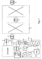
- a network 1 of ATM type is schematically illustrated that is intended for the transfer of data packets from an input terminal 3 to an output or destination terminal 5.
- the terminals 3, 5 may generally be both transmitters and receivers of the data packets and they may be present in any number, but in the Figure only one transmission direction and one input terminal and one output terminal are illustrated.
- the network generally comprises a multitude of intermediate switching nodes or switches, of which one is illustrated at 7. The switching units 7 are thus connected to other similar switching nodes, not shown.
- a terminal station 3 When a terminal station 3 requests to start issuing data packets into the network to the destination station 5, it will send some signal or message informing thereof to some switching node inside the network. This message also contains information requesting a specified transmission rate of the cells to be transmitted. Then a logical signal path through the network will be established by the exchange of various messages or control information between the switch units like 7 inside the network 1.
- a message or signal can be transmitted from the network 1 to the input terminal station 3, which has requested the connection, that the connection is now established and is ready to be used for the transfer of data packets from the input station 3.
- the input or source terminal 3 may itself receive messages or calls or the like from various sources, e.g. from another type network 9 through a suited bridge 11 and from a local area computer network 13 through a bridge 15 connected to a communication computer or server 17 in the LAN 13, which also may comprise various personal computers or work stations 19, a main server 20, etc.
- a high-speed workstation 21 can also be connected to the input terminal 3 through a suitable adapter card or unit for the workstation and a bridge 22.
- the input terminal 3 can itself be an integrated part of a communication device, e.g. in the shape of an accessory board mounted in a dedicated communication server.
- a solution of this problem could be to allot such a source a maximum data rate which is equal to or slightly higher than that which would be required by the source in the case there was provided a direct data path, without switching nodes and not interfered with by other traffic, therefrom to the destination.
- Another solution could be to introduce the concept that for some channels the information passes directly through a network, in particular that the cells belonging to such a channel always is transmitted directly from the stations or node. This will increase the complexity of the system.
- the time is considered to be divided into preferably equally long time slots TS and in each such time slot either one cell or no cell is transmitted from the terminal.
- a typical distance between the beginnings of two successive time slots should then correspond to the order of magnitude of the maximum output rate for the considered output link, what for a transmission rate of approximately 10 Megabit/second gives 42.4 microseconds.
- the distance is also, accordingly, at least 2.73 microseconds for a link of 155 Megabit/second.
- a maximum transmission rate is defined for each logical connection, the inverted value of which corresponds to a Minimum Distance between Time Slots, MDTS. This minimum distance can be expressed in multiples of the least possible time distance between successive cells in a considered network. If the transmission rate is assumed to be 10 Megabits/second with a minimum distance of two successive time slots of 42.4 ⁇ s, then an MDTS equal to 1 is equivalent to the maximum output rate, that is a cell time of 42.4 ⁇ s, which means that one cell belonging to the considered logical connection should maximally be transmitted in each time slot, that is no cells from other queues could then be transmitted.
- the same processing as in an input terminal 3 can also be executed in an internal node 7 of the network 1, since a new throttling of the cell rates may be needed due to unbalanced characteristics of the ATM-network, where some nodes may sometimes be inactive, some cells may be lost, internal buffering of varying capacities in the nodes, etc. Otherwise, some logical connections may have their cells temporarily transferred at a too high velocity through the network.
- a reception function 201 administrating messages, files, packets or cells respectively arriving at the terminal or node by a segmenting or division of the arrived data into suitable data segments such as ATM-cells.
- the reception function 201 manages the storing the cells in cell queues per logical connection, each having a connection identifier CEI, these identifiers then also defining each one a queue of cells associated with a considered connection.
- a throttling process or mechanism 203 the purpose of which is to inform the transmission function or cell generator 205 which cells are to be transmitted so that the cells are forwarded in the predetermined rates.
- the throttler process 203 need not exactly define the cell to transmit, but may only give the queue numbers or, equivalently, the logical connections, in a correct sequential order, so that in this case the transmission function takes the next connection number from the list and transmits the next cell in the queue arranged for this connection.
- the transmission function takes the next connection number from the list and transmits the next cell in the queue arranged for this connection.
- hereinafter also a procedure will be described in detail for the output handling.
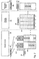
- the basic procedure performed in the reception function 201 is illustrated by the flow diagram of Fig. 3, the organization of the memory therefor being shown by fields or blocks at the bottom of Fig. 2.
- the reception function 201 handles the segmenting of data arriving at the input terminal or node and the storing of cells obtained from the data by storing the cells in queues arranged for the logical connections, which are currently present.
- a data packet or cell should arrive to an input register 207 of the terminal or node, the cell or the cells of which are to be stored in the reception registers or input buffers 209, see Fig. 2.
- These buffers 209 are thus established, one for each currently active or open logical connection, and are also called CEI queues, suitably numbered 1, 2, 3, ... or possibly having some other specific identification.
- connection number of the cells in the buffer is stored in a register 211
- the rate selector MDTS of the connection is stored in a register 213
- a pointer to the first stored cell in the buffer is stored in a field 215
- a pointer to the next position in the buffer where a new cell can be stored is stored in a register 217.
- an indicator for active state is stored, indicating whether the queue is active, that is whether the queue participates in the throttling process.
- the cells which are stored in a buffer 209 have not yet been transmitted from the station or node and a cell which is physically sent by the transmission function 205 is according to one embodiment always removed at that instance or in a preferred case such a cell is removed earlier from its CEI queue 209 as will be described hereinafter.
- the new information is processed in a block 303 and the information is assigned a logical connection number.
- Some logical connection number or equivalent data pointing to or implying a logical connection number can be extracted or retrieved from the packet or cell, for instance from the header portion of an ATM-cell, according to the protocol used. Then also some bits in the header or the entire header of a packet or cell can be removed, if required.
- the number of ATM-cells generated by the received data is also calculated.
- the logical connection number of the arrived data could also be determined in other ways, e.g. by hardware signals.
- a block 305 it is determined in a block 305 whether the input buffer for the logical connection of the information is active, that is if it participates in the throttling process and thus is present in any TS queue, to be described hereinafter. It is done by testing the indicator for active state stored in the memory field 221. If it is inactive, in a block 307 a signal is sent to the throttling function 203 telling that the considered queue now has become active again, and also the state indicator in the field 221 is changed to indicating that the queue is active. In a block 309, then a cell is stored in its associated buffer 209 at the position specified by the end position pointer stored in the field 217 and the end position pointer is then incremented one step cyclically.
- a block 311 it is determined in a block 311 whether there are more cells to be stored. If it not the case, the start block 301 is executed again. However, if there is another cell to be stored, a block 313 is executed where it is decided whether there is space in the considered buffer for another cell. It is made by comparing the start and end position pointers stored in the fields 215 and 217 respectively. If they are equal the buffer is full and then the procedure can wait until there is an empty space in the buffer, by returning repeatedly to this block 313. Alternatively, the cell can be discarded, as suggested by the block 315 drawn in dotted lines.
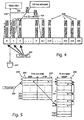
- Fig. 4 The operations performed by the throttling mechanism 203 are illustrated in Fig. 4, it being the critical step of the considered output handling, producing a queue of data cells to be forwarded in such a way that the previously ordered or commanded bit rates for each logical connection are achieved or at least and in any case not exceeded.
- TS queues there are a number of queues 223, called TS queues, each queue being associated with a considered, successive time slot TS which will physically occur at some time after the considered, present time.
- a TS pointer stored in a memory field 225 points to the next present or considered TS slot queue 223. Then from a considered starting time, i.e. that one to which the TS pointer in the field 225 points, each one of the next following time slots is associated with a corresponding TS queue 223, then such queues being arranged for the next 255 successive time slots.
- a TS queue 223 contains a list of numbers of CEIs, that is identification numbers of input queues 209, and it can be either empty or contain one or several CEI numbers.
- the CEI numbers in the TS queues or lists 223 are all different, that is each CEI number can only occur once in all of the CEI queues.
- the CEI numbers in a TS queue or lists 223 are arranged in a sequential order, the first CEI in a list pointing to the input buffer which at this time slot is next in turn or has the highest priority to be transmitted from the station.
- each logical TS queue has one beginning of queue pointer and one end of queue pointer pointing to the first CEI number and the last CEI number respectively in the considered TS queue.
- the physical number of TS queues which need to be arranged depends basically on the ratio between the smallest throttling rate, which can be assigned to a connection, and the total throttling rate of the station, and in the example described herein with a total transmission rate of 10 Megabit/second and standard channels of multiples of 64 kilobit/second a typical value could for instance be 256 TS queues. That means that at any moment, all time slots TS that have a position in time of 256 timeslots and later after the present, current time slot have empty, that is non-existent, queues.
- the identification number of a CEI queue which first has nothing to send and then gets cells to send is at a certain moment written into one of the TS queues 223, as will be described below and is signalled by the reception function 201 in the block 319 as has been described above.
- the procedure when the throttling machine 203 is supposed to find a CEI queue from which the next cell is to be sent is:
- this CEI value is added to the TS queue 23 from which a cell is next to be sent, i.e. to the TS queue having the number (TSP + 1), in the preferred case inserted after possible other CEI queue numbers present in this TS queue.
- this TS queue is empty, this first cell of the activated queue will then be transmitted in the next TS, meaning that the transmission from a new queue or a queue, which has returned to an active state, is started immediately.
- a CEI number will be written back into a later TS queue 223 also when the last cell currently in the CEI packet queue 13 has been transmitted or at least has been transferred to be handled by the transmission function 205.
- This CEI number will instead be removed from the TS queues, i.e. not written back, at the next time when the throttling machine 203 selects this CEI as the one from which a cell is to sent, but of course, only in the case where no new cell in the meantime has been entered in the considered CEI queue 209, compare blocks 317 and 319 of Fig. 3.
- the reason for this is to guarantee a cell distance of at least MDTS also for the case when a new packet, that is a group of cells, is ready for transmission just after the last cell of the previous packet was transmitted. That means that when the cells of a new packet get ready for throttling and transmission and the CEI value is not already written into or found in any TS queue, it is possible to select the earliest possible time slot for transmission of the first cell of the packet. Otherwise, it could occur that a source would feed the station with packets or cells in a suitable rate such that first always one, the only cell in the queue was transmitted, the queue was then found empty and then immediately there was a new cell to send from the queue, throttling this cell to the next successive time slot.
- the TS queues 223 may not be physical lists or memories, as has already been indicated, but can, since each CEI queue number occurs maximally once in the TS queues 223, be replaced by a linked list as illustrated by the schematic picture of Fig. 5 which is drawn for the particular case of 256 TS queues 223 and maximally 1024 positions in each TS queue, allowing thus maximally 1024 established logical connections to be handled.
- the corresponding flow diagrams of the TS queue handling are shown in Fig. 6.
- TS queue table 233 comprising for each successive time slot TS two pointers BTSP 235 and ETSP 237 and one TS link table 239 comprising pointers NTEP pointing to another positions in this table 239 itself.
- the first pointer 235 BTSP, Beginning of TS Queue Pointers, in the TS table 233 points to a position in the second table, the TS link table 239, the number or address of this position in this second table 239 then being the CEI number of a queue 209 from which a cell first should be sent for this time slot queue, the time slot or time slot queue being the address or number of the field containing the considered pointer BTSP in the TS queue table list 233.
- An empty TS queue is indicated by giving the beginning pointer BTSP some easily identifiable value, such as the logical value "nul". Also the value 0 can be used, pointing to the empty cell pattern queue. For a TS queue holding only one CEI number the pointers BTSP and ETSP are equal.
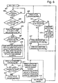
- a flow diagram is shown for the handling of the next time slot queue 223, performed by the throttling function 203, as illustrated in Fig. 4, in particular as indicated by the arrows 428 and 429 and the bucket 427, and using the linked list of Fig. 5.
- the procedure starts in a block 601, where the time slot pointer TSP stored in the field 225 is incremented by one step.
- a block 602 is then executed, where it is sensed, whether it is possible to send the cell now, or as is illustrated, according to another preferred alternative, whether there is a free space in a transmit buffer of the transmission function 205.
- the same block 602 is repeated until the question of the block gives the answer yes, and then in a block 603 the pointer BTSP in the field 235 of the TS queue table 233 is accessed and it is tested if the value thereof is nul. If it is not, the present TS queue is not empty and then in a block 605 the pointer value which is a CEI queue number, is temporarily stored in a suitable register, not shown. Then in a block 607 it is decided whether the accessed pointer is equal to the corresponding end pointer, i.e. the pointer ETSP in the field 237 of the TS queue table 233.
- a block 609 is performed where the linked list for the next time slot as indicated by the time slot pointer value (TSP + 1) is modified.
- TSP + 1 the pointer BTSP at this next time slot (TSP + 1) is written to the field NTSEP in the position in the TS link table 239 as pointed to by the ETSP pointer at the current TSP.
- the BTSP field 235 of the next time slot as indicated by the value (TSP + 1) the linked CEI number in the NTSEP field of the link table as pointed to by the pointer BTSP of the current TSP.
- a block 611 which is also performed in the case where the determination in the block 607 gave a positive answer, that is if there is only one CEI number in the TS list, in the BTSP pointer in the field 233 for the current time slot the value nul or the value for CEI No. 0 is written, its value being also conveniently equal to zero.
- the CEI queue having identification number zero, CEI No. 0, is used, as been suggested above, for indicating an empty position or that nothing is to be transmitted and it contains an address pointer to an empty cell pattern stored in a register 249, see Fig. 2.
- a block 615 is executed, where it is tested whether the CEI queue as indicated by the value temporarily stored in the block 605 is empty. If it is empty, a block 617 is executed where an empty pattern is sent to the transmission function 205 and then in block 618 the indicator for active state of the considered CEI queue 209 as stored in the field 221 is set to indicate that the CEI queue is not active any longer. Then the TS pointer incrementing step 601 is executed again.
- the next cell that is the cyclically first cell, is delivered to the transmission function 205, for instance to be stored in the transmit FIFO memory, as illustrated by a block 619. Then also the start position pointer stored in the field 215 for this CEI queue in the reception function 201 is incremented one step. The procedure can stop here and wait until the transmission function 205 has time to send or when it is time to send the next cell.
- an output buffering can be used, as is suggested in Fig. 2.
- a cell from the selected input buffer 209 (or possibly an address thereof) is written to the last position of an output FIFO memory 241 or transmit queue.
- the transmit memory 241 can conveniently be a cyclical memory, the start of occupied positions being indicated by a start pointer stored in a memory field 243 and the position after the last occupied position being indicated by an end pointer stored in a memory field 245.
- this end pointer 245 is incremented cyclically one step.
- start and end position pointers in the fields 243 and 245 may be compared, some device being provided for distinguishing between the cases where the output FIFO 241 is empty or full. For instance, an equal value of the start and end positions pointers may be taken to always indicate an empty state of the buffer and a value of the start position pointer being cyclically directly after the value of the end position pointer may be taken to indicate that the memory is full.
- the very procedure essential to the throttling is performed, where a CEI queue number is added to a later TS queue 209, compare the arrow 431 in Fig. 4.
- a block 621 it is decided whether the TS queue associated with this later time slot, as obtained from the considered one and added thereto the number MDTS in the field 213 for this CEI queue 209, symbolically indicated by the number (TSP + MDTS), is empty.
- a block 623 is executed, where the value or pointer of the BTSP field at this later time slot queue is written to the NTSEP field in the TS link table 239 at the position indicated by the CEI queue identification number. Then in a block 625 the considered CEI identification number is written to the beginning of queue pointer BTSP in the field 235 for this later time slot queue (TSP + MDTS). After that, the proper throttling function has been completed by the rearrangement of the TS queues and the next TS queue 223 will be handled by executing the block 601 where the TS pointer is incremented.
- a block 627 is executed, where the current CEI value, i.e. the value which was used in the delivery of a cell to the output FIFO queue 241 in the block 619, is written to the end pointer ETSP field 237 for this later time slot queue at (TSP + MDTS).
- the block 625 is performed as above.
- this special case is indicated to the cell transmitter 205, as has been already mentioned, by delivering a special empty cell position ECP pattern, e.g. as stored in a memory 249.
- a block 633 is executed, where this fact is signalled to the transmit function 205, such as by transferring an empty cell pattern thereto as has been discussed above. Then a new time slot queue will be handled by incrementing the time slot pointer in the block 601.
- One small change in the algorithm as described above can be made for the case including a transmission FIFO-buffer 241.
- the case to consider is when the throttling function 203 finds a CEI queue 209 from which it is allowed to transmit, but that this CEI has an empty cell queue 209 and thus has nothing to send, compare blocks 615 and 617 of Fig. 6.
- the throttling function 203 instead of writing an ECP into the output FIFO 241, it would be possible for the throttling function 203 to find a new CEI queue 209, from which it is allowed to send on this TS, however this being applicable only for the case when there are more than one CEI queue number in the time slot queue 223 of the current TS pointed to by the TS pointer stored in the field 225.
- Most of the throttling algorithm may, for moderate maximum transmission rates, be implemented in software in the throttling mechanism 203, this software being for instance included in or including the relatively small software portions which can be arranged for the two other mechanisms, the reception function 201 and the transmission function 205, if they are not hard-wired constructions.
- the parts of the cell handling as described above which are most memory-consuming are in any case the memory areas for the input buffers 209.
- hardware constructions are necessary, and the various processes described herein may then, in the conventional way, be executed by specialized state machines implemented in digital signal processors particularly constructed for the purpose.
- the input buffers can be replaced by a random storage memory requiring an address list of empty spaces and address lists instead of the input buffers 209.
- the processor of the throttling mechanism 203 can indicate for the cell transmitter 205 each time when a cell is not to be transmitted at a certain TS. This can be achieved, as been mentioned above, by providing to the transmission function a special empty cell position ECP pattern stored in the memory 249.
- the writing into the transmit FIFO 241 must cease, compare the discussion of the block 602 of Fig. 6 above, when the fill level, as indicated by some fill counter, has reached a predetermined threshold.
- This threshold corresponds to a certain maximum cell latency time, and is proportional to the time it takes until the output FIFO 241 goes empty in case it is not refilled.
- the throttling mechanism 203 it is necessary for the throttling mechanism 203 to avoid that the transmit FIFO 241 goes empty. At times when there is nothing to send, the throttling mechanism 203 will feed the output FIFO 241 with ECP patterns.
- the cell transmission function 205 can restart as soon as the first cell is written into the output FIFO 241.
- the throttling function 203 could thus let the output FIFO 241 go empty in the case where it knows that there are no cells to transmit, i.e. there are no CEIs in the TS throttling queues 223 or there are no active CEI queues 209.
- FIG. 7 A flow diagram of the procedure performed by the transmission function 205 in the embodiment where an output FIFO 241 is used, is shown in Fig. 7, the procedure starting in a block 701, where it is tested whether it is now the next time for physically sending a cell from the terminal or node and it is also tested whether there is at least one cell or ECP stored in the output FIFO 241. In the case where any of these two conditions is not satisfied, the same block is executed again. If instead the conditions fulfilled, that is when the time for sending is achieved and the output FIFO memory is not empty, the next cell stored in the transmit FIFO 241, as pointed to by the start pointer stored in the register 243, is accessed in a block 703.
- this cell is tested in a block 705, if it is the empty cell pattern ECP (CEI queue No. 0). If it is the case, the block 701 is performed again for awaiting the next time to send and for testing that the output FIFO is not empty, otherwise in a block 707 this next cell is physically sent from the station, which includes that it is transferred to an output register 250, from which it is transmitted from the station. Finally in the block 707 the start position pointer stored in the field 243 for the transmit FIFO 241 is incremented cyclically by one step.
- ECP empty cell pattern
- time slot queue No. n comprises three items, the queues CEI 1, CEI 2 and CEI 3.
- time slot queue No. (n+2) there is only the CEI queue No. 4.
- the TS pointer in field 225 points to the TS queue No. n.
- a next cell from CEI queue No. 1 is placed in the output queue or transmit FIFO. Then also the CEI queue No. 1 is placed in the TS queue No. (n+4), as prescribed by the MDTS value of this CEI queue and as indicated by the arrow 801. The remaining CEI queues in the TS queue are transferred to the next TS queue (n+1), that is this new TS queue will comprise the CEI queues having Nos. 2 and 3 respectively.
- CEI queue No. 2 Before the TS pointer in the field 225 is stepped again, the next cell from CEI queue No. 2 will be entered in the transmit FIFO 241, CEI queue No. 2 will be added to TS queue No. (n+7), and the CEI queue No. 3 will be pushed into or inserted before all other CEI queue numbers in the next TS queue having the number (n+2).
- the cyclically first cell of CEI queue No. 3 is sent to the FIFO memory 241, CEI queue No. 4 is pushed to the next TS queue (n+3) and CEI queue No. 3 is added to the TS queue No. (n+ 10).
- the fill level in the transmit FIFO 241 can fluctuate is shown by the diagram of Fig. 11.
- the fill level is illustrated as a curve comprising straight line segments, the upper endpoints of the segments being located at the maximum fill level, the upper threshold level of the memory.
- the transmission function 205 can be assumed to be always working at a constant rate, reading one cell or ECP from the output FIFO 241 at each time slot.
- the throttling mechanism 203 is however assumed to be active only at some short intermittent time intervals, these intervals being illustrated by the activity curve of Fig. 12. Further, the handling by the throttling mechanism 203 of each TS queue 223 can be assumed to always require a for instance substantially constant or equal time period resulting in a very high throttling rate during the activity periods of the throttling mechanism 223.
- the fill level of the transmit FIFO increases at a constant rate, up to the maximum fill level, and it decreases at a constant rate during the time periods when the throttling mechanism 203 is inactive and only the transmit function is working.
- the transmit FIFO 241 cannot accept any more cells and then there is a wait or delay period, when the throttling mechanism 203 has to be inactive waiting that there will be empty space in the output FIFO 241.
- Fig. 11 it is assumed that when the maximum fill level of the transmit buffer is reached, some signal is issued to stop the throttling function 203. This can also be achieved by the throttling mechanism itself by performing a suitable test of the output buffer, compare the discussion of the block 602 of Fig. 6.
- the throttling task can be restarted at any time and a signal can for instance be sent to the throttling task when the output FIFO is close to empty. The issuing of such a signal could then be made suitably in the block 707 of Fig. 7. Alternatively a signal from a timer circuit can be used for the restart of the throttling mechanism.
Abstract
Description
- Fig. 1 is a schematic view of a network,
- Fig. 2 is a block diagram of a terminal,
- Fig. 3 is a flow diagram showing the function steps executed by the reception function,
- Fig. 4 illustrates the cell throttling principle,
- Fig. 5 shows logical queues and their interconnection,
- Fig. 6 is a flow diagram showing processes for modifying throttling queues,
- Fig. 7 is a flow diagram showing process steps performed by a transmission function,
- Figs. 8 and 9 illustrate an example of the throttling process,
- Fig. 10 schematically shows a FIFO-memory used for transmission in the throttling example of Figs. 9 and 10,
- Fig. 11 shows an example of a time diagram of the filling level of the FIFO-memory,
- Fig. 12 shows, for the example of Fig. 11, a time diagram of the activity for the transmit task.
- a smooth cell flow at the physical output interface (comfortable for the ATM switch, which can easily be multiplexed with cell flows from other modules),
- simple hardware,
- rates which can be set individually per connection with high resolutions,
- no delay for the first cell in a packet or message, in the output FIFO case except the transmission time for cells already waiting in the output FIFO,
- true peak allocators, i.e. cells are never transmitted more closely than a certain guaranteed distance,
- it is easy to change the rate of a connection during operation, for congestion control or for mean throttling.
Claims (23)
- A method for transmitting data segments from a station, wherein data arrives at the station from various logical and/or physical sources (9, 21, 19),
the method including the steps of:characterized by the additional step of:deriving, from the data segments arriving at the station from each of said sources, data segments, andtransmitting, at successive times, the data segments one at a time from the station,arranging for each of successive times, from a considered current time, a logical or physical queue (223), the first of said queues being the next one, as considered from the current time, the second of said queues being the queue after the first one, etc., each one of the queues comprising in a consecutive order, identifiers of those sources (9, 21, 19) for which a data segment of theirs is to be transmitted or the data segments themselves or addresses thereof, the first position in each of the queues indicating directly, or indirectly in the case where it contains a data segment or an address thereof, respectively, the source, for which a data segment is to be sent with the highest degree of priority, the other positions of the queue indicating sources which have lower degrees of priority in a decreasing order,the step of transmitting including the following repeated steps:transmitting a first or next data segment from the source first indicated in the first queue or the first data segment in or as indicated first in the first queue,thereafter transferring (429) the remaining part of the first queue to the next queue and placing it in front of all the items in this next queue,thereafter removing the first queue and renumbering the remaining queues, so that the next queue becomes the first one, etc., maintaining the sequential order of the queues (223), andimmediately before or after the step of removing the first queue, adding an identifier of the same data source or adding a next data segment or adding an address thereof from the same source, from which a data segment was transmitted, to that queue, which has a distance from the removed queue in the sequential order of queues, where this distance is a minimum distance between time slots determined from a maximum transmission rate required for or assigned to the source, from which those data arrived from which the data segment was derived,whereby said transmission rate, for each of said sources (9, 21, 19), is not exceeded for the data segments derived from the data arriving from the source. - A method according to claim 1, characterized in that the adding is made first in that queue.
- A method according to any of claims 1 - 2, characterized by arranging queues (223) for only a predetermined number of successive times, the step of transmitting including that the steps of:are executed in this order and that between these steps the following step is executed:removing the first queue and renumbering the remaining queues, andadding an identifier or a next data segment or an address,adding a last queue to the set of queues (223), the last queue being empty.
- A method according to any of claims 1 - 3, characterized in that in the step of transmitting, when a first or next data segment is to be transmitted, it is placed in or an indication of the data segment is placed in an output buffer (241), from which it is physically transmitted (250) from the station.
- A method according to any of claims 1 - 4, characterized in that when the first queue is empty, no data segment is transmitted.
- A method according to any of claim 1 - 5, characterized in that when the first queue is empty, a special data segment (249) or an indication thereof is placed in an output buffer (241), this special data segment not being transmitted from the station.
- A method according to claim 6, in the case where the transmitting of data segments is made periodically, characterized in that transmission of data segments is made sequentially from the segments stored in the output buffer (241), one at each of periodically repeated times, and in the case where the special data segment (249) or an indication thereof is located at the next position in the output buffer where a data segment should be stored and is to be transmitted, no data segment is transmitted at the corresponding periodic time.
- A method according to any of claims 1 - 7, characterized by the additional step of adding, in the case where a source (9, 21, 19) that has not previously had an identifier of itself or any of its data segments or addresses thereof in any queue (223), starts to be active, i.e. has at least one data segment to transmit, an identifier of itself or the next one of its data segments or an address thereof, to the queue, which is the next one after the current one.
- A method according to claim 8, characterized in that the addition is made last in that queue.
- A method according to any of claim 1 - 9, characterized in that in deriving data segments from data arriving at the station, each data segment is given the same length.
- A method according to any of claims 1 - 10, characterized in that in transmitting data segments from the station, the data segments are transmitted (250) periodically.
- A station for transmitting data segments therefrom, wherein data arrives at the station from various logical and/or physical sources (9, 21, 19) and data segments are derived from the data arriving from each of the sources, the station comprising:characterized bytransmission means (205, 250) for transmitting at successive times the data segments, one at a time,memory means for storing, for each one of successive times from a considered current time, a logical or physical queue (223), the first of said queues being the next one, as considered from the current time, the memory means having fields for storing, for each one of the queues comprising in a consecutive order, identifiers of those sources for which a data segment of theirs is to be transmitted or the data segments themselves or addresses thereof, the first position of each queue indicating directly, or indirectly by holding a data segment or an address thereof belonging to it, the source, for which a data segment is to sent with the highest degree of priority, the other positions of the queue indicating in the same way sources which have lower degrees of priority in a decreasing order, andcontrol means for executing the following repeated steps:transmitting a first or next data segment from the source first indicated in the first queue or the first data segment in or as indicated first in the first queue,thereafter transferring (429) the remaining part of the first queue to the next queue and placing it in front of all the items in this next queue,thereafter removing the first queue and renumbering the remaining queues, so that the next queue becomes the first one, etc., maintaining the sequential order of the queues (223), andimmediately before or after the step of removing the first queue, adding an identifier of the same data source or adding a next data segment or adding an address thereof from the same source, from which a data segment was transmitted, to that queue, which has a distance from the removed queue in the sequential order of queues, where this distance is a minimum distance between time slots determined from a maximum transmission rate required for or assigned to the source, from which those data arrived from which the data segment was derived,whereby said transmission rate, for each of said sources (9, 21, 19), is not exceeded for the data segments derived from the data arriving from the source.
- A station according to claim 12, characterized in that the control means are arranged to make the adding first in that queue.
- A station according to any of claims 12 - 13, characterized inthat the memory means are arranged for storing only a predetermined number of successive queues (223), andthat the control means are arranged to add, after removing the first queue and renumbering, a last queue to the set of queues (223), this last queue being empty and stored in the fields of the removed queue.
- A station according to claim 14, characterized in that the memory means are arranged to store the queues (223) in a cyclical manner, a memory field being provided for storing a pointer (225) pointing to a current one of the queues.
- A station according to any of claims 12 - 15, characterized by an output buffer (241) included in the transmission means,the control means arranged to place, when a data segment is to be transmitted, the data segment or an indication thereof in the output buffer (241), from which it is physically transmitted (250) from the station, andthe transmission means arranged to transmit data segments stored in the output buffer (241) in a first in-first out manner.
- A station according to any of claims 12 - 16, characterized in that the control means are arranged to sense when the first queue is empty and then not to transmit any data segment.
- A station according to claim 16, characterized inthat the control means are arranged to sense the case when the first queue is empty and then to place a special data segment (249) or an indication thereof in the output buffer (241), andthat the transmission means are arranged not to transmit, when this special data segment (249) is found in the output buffer (241), any data segment from the station.
- A station according to any of claims 12 - 18, characterized in that the memory means for storing the source identifiers are arranged to store a predetermined number of queues (223), the queues being organized cyclically in a sequential order, a register being arranged for storing a pointer (225) indicating the considered current queue, the pointer being updated by the control means when the current queue is removed.
- A station according to any of claims 12 - 19, characterized in that the control means are arranged to perform the additional step of storing, when a source (9, 21, 19) that has not previously had an identifier of itself or any of its data segments or addresses thereof respectively stored in any of the memory means for the queues (223), starts to be active, i.e. has at least one data segment to transmit, an identifier of that source or the next one of its data segments or an address thereof, in the memory means for the queue, which is the next one after the current one.
- A station according to claim 20, characterized in that the control means are arranged to store the new identifier or the next one of the data segments or an address thereof respectively last in that queue.
- A station according to any of claims 12 - 21 for the case where the memory means are arranged for storing queues (223) comprising identifiers of sources, characterized in that the memory means for storing the source identifiers are arranged as a linked list, comprisingfirst memory means comprising fields (235) for storing the first items in each queue (223),second memory means comprising fields (237) for storing the last items in each queue (223),third memory means comprising fields (239) in a sequential order, each field having a sequential order number, the fields being arranged for storing next items in the queues, the sequential order number of a field indicating the item immediately before the item stored in the field.
- A station according to any of claims 12 - 22, characterized in that the transmission means (205, 250) are arranged to transmit the data segments at evenly or uniformly distributed times.
Applications Claiming Priority (3)
| Application Number | Priority Date | Filing Date | Title |
|---|---|---|---|
| SE9502468 | 1995-07-06 | ||
| SE9502468A SE506955C2 (en) | 1995-07-06 | 1995-07-06 | ATM flow control |
| PCT/SE1996/000887 WO1997002686A1 (en) | 1995-07-06 | 1996-07-05 | Atm throttling |
Publications (2)
| Publication Number | Publication Date |
|---|---|
| EP0873624A1 EP0873624A1 (en) | 1998-10-28 |
| EP0873624B1 true EP0873624B1 (en) | 2005-11-02 |
Family
ID=20398884
Family Applications (1)
| Application Number | Title | Priority Date | Filing Date |
|---|---|---|---|
| EP96923149A Expired - Lifetime EP0873624B1 (en) | 1995-07-06 | 1996-07-05 | Atm throttling |
Country Status (11)
| Country | Link |
|---|---|
| US (2) | US5729529A (en) |
| EP (1) | EP0873624B1 (en) |
| JP (1) | JPH11508749A (en) |
| CN (1) | CN1097913C (en) |
| AU (1) | AU707294B2 (en) |
| CA (1) | CA2226009A1 (en) |
| DE (1) | DE69635379T2 (en) |
| HK (1) | HK1015584A1 (en) |
| NO (1) | NO976149L (en) |
| SE (1) | SE506955C2 (en) |
| WO (1) | WO1997002686A1 (en) |
Families Citing this family (35)
| Publication number | Priority date | Publication date | Assignee | Title |
|---|---|---|---|---|
| US5668570A (en) * | 1993-06-29 | 1997-09-16 | Ditzik; Richard J. | Desktop computer with adjustable flat panel screen |
| US5936967A (en) * | 1994-10-17 | 1999-08-10 | Lucent Technologies, Inc. | Multi-channel broadband adaptation processing |
| SE506955C2 (en) * | 1995-07-06 | 1998-03-09 | Ericsson Telefon Ab L M | ATM flow control |
| US6175883B1 (en) * | 1995-11-21 | 2001-01-16 | Quantum Corporation | System for increasing data transfer rate using sychronous DMA transfer protocol by reducing a timing delay at both sending and receiving devices |
| US6134217A (en) * | 1996-04-15 | 2000-10-17 | The Regents Of The University Of California | Traffic scheduling system and method for packet-switched networks with fairness and low latency |
| US6195333B1 (en) * | 1996-10-28 | 2001-02-27 | Fujitsu Network Communications, Inc. | Unframed isochronous shaping method to reduce delay and delay variation in a CBR transmission system |
| JP3462024B2 (en) * | 1996-12-04 | 2003-11-05 | 株式会社東芝 | Transmission control method for network system |
| KR19990008775A (en) * | 1997-07-03 | 1999-02-05 | 윤종용 | Socket for Noise Reduction |
| US6026451A (en) * | 1997-12-22 | 2000-02-15 | Intel Corporation | System for controlling a dispatch of requested data packets by generating size signals for buffer space availability and preventing a dispatch prior to a data request granted signal asserted |
| ES2145718B1 (en) * | 1998-09-23 | 2001-02-01 | Telefonica Sa | METHOD AND APPARATUS FOR TRAFFIC MOLDING MTA. |
| US6182183B1 (en) * | 1998-11-13 | 2001-01-30 | Sonics, Inc. | Communications system and method with multilevel connection identification |
| JP2001177575A (en) * | 1999-12-20 | 2001-06-29 | Nec Corp | Preferential control system |
| KR100357628B1 (en) * | 1999-12-28 | 2002-10-25 | 삼성전자 주식회사 | Cell processing apparatus having priority queue and method thereof in an asynchronous transfer mode system |
| US7325221B1 (en) | 2000-08-08 | 2008-01-29 | Sonics, Incorporated | Logic system with configurable interface |
| US7165094B2 (en) * | 2001-03-09 | 2007-01-16 | Sonics, Inc. | Communications system and method with non-blocking shared interface |
| US20030004699A1 (en) * | 2001-06-04 | 2003-01-02 | Choi Charles Y. | Method and apparatus for evaluating an integrated circuit model |
| US7086059B2 (en) * | 2001-06-26 | 2006-08-01 | Intel Corporation | Throttling queue |
| US7414976B2 (en) * | 2003-12-16 | 2008-08-19 | Intel Corporation | Method and apparatus to implement operation and maintenance (OAM) functions on a network processor |
| CN1311350C (en) * | 2004-04-30 | 2007-04-18 | 华为技术有限公司 | Method for triggering queue management by sending events in communication queue management |
| KR100620372B1 (en) * | 2004-08-18 | 2006-09-08 | 삼성전자주식회사 | Method for rotating image, computer and recoding media |
| US7505410B2 (en) * | 2005-06-30 | 2009-03-17 | Intel Corporation | Method and apparatus to support efficient check-point and role-back operations for flow-controlled queues in network devices |
| US20080141063A1 (en) * | 2006-12-12 | 2008-06-12 | Ridgeway Curtis A | Real time elastic FIFO latency optimization |
| US8909764B2 (en) | 2011-07-28 | 2014-12-09 | Xyratex Technology Limited | Data communication method and apparatus |
| US10069748B2 (en) | 2015-12-14 | 2018-09-04 | Mellanox Technologies Tlv Ltd. | Congestion estimation for multi-priority traffic |
| US10069701B2 (en) | 2016-01-13 | 2018-09-04 | Mellanox Technologies Tlv Ltd. | Flexible allocation of packet buffers |
| US10250530B2 (en) | 2016-03-08 | 2019-04-02 | Mellanox Technologies Tlv Ltd. | Flexible buffer allocation in a network switch |
| US10084716B2 (en) | 2016-03-20 | 2018-09-25 | Mellanox Technologies Tlv Ltd. | Flexible application of congestion control measures |
| US10205683B2 (en) * | 2016-03-28 | 2019-02-12 | Mellanox Technologies Tlv Ltd. | Optimizing buffer allocation for network flow control |
| US10387074B2 (en) | 2016-05-23 | 2019-08-20 | Mellanox Technologies Tlv Ltd. | Efficient use of buffer space in a network switch |
| US9985910B2 (en) | 2016-06-28 | 2018-05-29 | Mellanox Technologies Tlv Ltd. | Adaptive flow prioritization |
| US10389646B2 (en) | 2017-02-15 | 2019-08-20 | Mellanox Technologies Tlv Ltd. | Evading congestion spreading for victim flows |
| US10645033B2 (en) | 2017-03-27 | 2020-05-05 | Mellanox Technologies Tlv Ltd. | Buffer optimization in modular switches |
| US11005770B2 (en) | 2019-06-16 | 2021-05-11 | Mellanox Technologies Tlv Ltd. | Listing congestion notification packet generation by switch |
| US10999221B2 (en) | 2019-07-02 | 2021-05-04 | Mellanox Technologies Tlv Ltd. | Transaction based scheduling |
| US11470010B2 (en) | 2020-02-06 | 2022-10-11 | Mellanox Technologies, Ltd. | Head-of-queue blocking for multiple lossless queues |
Family Cites Families (27)
| Publication number | Priority date | Publication date | Assignee | Title |
|---|---|---|---|---|
| DE3331205A1 (en) * | 1983-08-30 | 1985-03-14 | Telefunken Fernseh Und Rundfunk Gmbh, 3000 Hannover | SYNCHRONOUS PATTERN |
| FR2563398B1 (en) * | 1984-04-20 | 1986-06-13 | Bojarski Alain | METHOD AND DEVICE FOR RECOVERING THE FRAME LOCK FOR A FRAME LOCKING WORD WITH BIT DISTRIBUTED IN THE FRAME |
| US4930125A (en) * | 1989-01-30 | 1990-05-29 | General Datacom, Inc. | Multiplexer frame synchronization technique |
| KR920009679B1 (en) * | 1990-06-27 | 1992-10-22 | 재단법인 한국전자통신연구소 | Fast atm cell synchronus switching system having switching memory |
| US5331641A (en) * | 1990-07-27 | 1994-07-19 | Transwitch Corp. | Methods and apparatus for retiming and realignment of STS-1 signals into STS-3 type signal |
| EP0487235B1 (en) | 1990-11-21 | 1999-02-03 | AT&T Corp. | Bandwidth and congestion management in accessing broadband ISDN networks |
| US5166930A (en) * | 1990-12-17 | 1992-11-24 | At&T Bell Laboratories | Data channel scheduling discipline arrangement and method |
| DE59105393D1 (en) * | 1991-02-01 | 1995-06-08 | Siemens Ag | Method for monitoring and smoothing data streams that are transmitted using an asynchronous transmission method. |
| US5285441A (en) * | 1992-03-17 | 1994-02-08 | At&T Bell Laboratories | Errorless line protection switching in asynchronous transer mode (ATM) communications systems |
| US5381407A (en) * | 1992-06-04 | 1995-01-10 | Bell Communications Research, Inc. | Method and system for controlling user traffic to a fast packet switching system |
| GB2268372B (en) | 1992-06-11 | 1995-11-01 | Roke Manor Research | Improvements in or relating to data transmission systems |
| JPH06169320A (en) * | 1992-10-02 | 1994-06-14 | Toshiba Corp | Atm cell making device |
| CA2105268C (en) * | 1992-12-28 | 1999-07-13 | Shahrukh S. Merchant | Resynchronization of asynchronous transfer mode (atm) switch fabric |
| FR2700902B1 (en) | 1993-01-22 | 1995-02-24 | Thomson Csf | Method for managing the bit rate of digitally coded messages transported by an asynchronous network, in particular an ATM network, and device for its implementation. |
| US5412655A (en) * | 1993-01-29 | 1995-05-02 | Nec Corporation | Multiprocessing system for assembly/disassembly of asynchronous transfer mode cells |
| DE69429200T2 (en) * | 1993-02-15 | 2002-07-18 | Mitsubishi Electric Corp | Data queuing device and ATM cell switching based on push and search |
| DE4316225C2 (en) * | 1993-05-14 | 2000-06-08 | Deutsche Telekom Ag | Method and arrangement for interference-free clock recovery on the receiver side for digital signals with constant bit rate |
| FR2707023B1 (en) * | 1993-06-24 | 1995-09-22 | Boyer Jacqueline | |
| JPH0779226A (en) * | 1993-09-07 | 1995-03-20 | Fujitsu Ltd | Circuit for controlling plural channel transmission cell bands |
| EP0679270A1 (en) | 1993-11-15 | 1995-11-02 | Hughes Aircraft Company | A method and system for maintaining access security of input and output operations in a computer system |
| CA2145017C (en) * | 1994-03-31 | 2000-02-15 | Masaru Murakami | Cell multiplexer having cell delineation function |
| US5491691A (en) * | 1994-08-16 | 1996-02-13 | Motorola, Inc. | Method and apparatus for pacing asynchronous transfer mode (ATM) data cell transmission |
| US5533020A (en) * | 1994-10-31 | 1996-07-02 | International Business Machines Corporation | ATM cell scheduler |
| US5602853A (en) * | 1994-11-03 | 1997-02-11 | Digital Equipment Corporation | Method and apparatus for segmentation and reassembly of ATM packets using only dynamic ram as local memory for the reassembly process |
| US5535201A (en) * | 1995-05-10 | 1996-07-09 | Mitsubishi Electric Research Laboratories, Inc. | Traffic shaping system using two dimensional timing chains |
| SE506955C2 (en) * | 1995-07-06 | 1998-03-09 | Ericsson Telefon Ab L M | ATM flow control |
| US5610921A (en) * | 1995-08-31 | 1997-03-11 | Sun Microsystems, Inc. | Scalable architecture for asynchronous transfer mode segmentation and reassembly |
-
1995
- 1995-07-06 SE SE9502468A patent/SE506955C2/en not_active IP Right Cessation
- 1995-12-29 US US08/581,325 patent/US5729529A/en not_active Expired - Lifetime
-
1996
- 1996-07-05 DE DE69635379T patent/DE69635379T2/en not_active Expired - Lifetime
- 1996-07-05 EP EP96923149A patent/EP0873624B1/en not_active Expired - Lifetime
- 1996-07-05 JP JP9505076A patent/JPH11508749A/en active Pending
- 1996-07-05 WO PCT/SE1996/000887 patent/WO1997002686A1/en active IP Right Grant
- 1996-07-05 CN CN96195299A patent/CN1097913C/en not_active Expired - Fee Related
- 1996-07-05 AU AU63740/96A patent/AU707294B2/en not_active Ceased
- 1996-07-05 CA CA002226009A patent/CA2226009A1/en not_active Abandoned
-
1997
- 1997-12-30 NO NO976149A patent/NO976149L/en unknown
-
1998
- 1998-01-05 US US09/002,773 patent/US6594263B1/en not_active Expired - Lifetime
-
1999
- 1999-02-12 HK HK99100602A patent/HK1015584A1/en not_active IP Right Cessation
Also Published As
| Publication number | Publication date |
|---|---|
| SE9502468D0 (en) | 1995-07-06 |
| NO976149D0 (en) | 1997-12-30 |
| CN1097913C (en) | 2003-01-01 |
| SE9502468L (en) | 1997-01-07 |
| JPH11508749A (en) | 1999-07-27 |
| DE69635379D1 (en) | 2005-12-08 |
| US5729529A (en) | 1998-03-17 |
| CN1190512A (en) | 1998-08-12 |
| HK1015584A1 (en) | 1999-10-15 |
| AU6374096A (en) | 1997-02-05 |
| CA2226009A1 (en) | 1997-01-23 |
| SE506955C2 (en) | 1998-03-09 |
| US6594263B1 (en) | 2003-07-15 |
| NO976149L (en) | 1998-03-04 |
| EP0873624A1 (en) | 1998-10-28 |
| WO1997002686A1 (en) | 1997-01-23 |
| DE69635379T2 (en) | 2006-06-22 |
| AU707294B2 (en) | 1999-07-08 |
Similar Documents
| Publication | Publication Date | Title |
|---|---|---|
| EP0873624B1 (en) | Atm throttling | |
| US5938749A (en) | Queue measurement apparatus and methodology | |
| US6141323A (en) | Closed loop congestion control using a queue measurement system | |
| US5640389A (en) | Traffic shaper and packet communication apparatus | |
| US5987008A (en) | ATM switch | |
| JP4209940B2 (en) | Broadband switching network | |
| CA2214838C (en) | Broadband switching system | |
| AU719514B2 (en) | Broadband switching system | |
| EP0113545A1 (en) | Packet error rate measurements by distributed controllers | |
| US6128306A (en) | Cell queue formation in an ATM switch | |
| JPH06197130A (en) | High-speed packet switching device and method for routing data packet | |
| JPH07321823A (en) | Device with multi-casting function | |
| US6144640A (en) | ATM switch | |
| US6504824B1 (en) | Apparatus and method for managing rate band | |
| US6046982A (en) | Method and apparatus for reducing data loss in data transfer devices | |
| EP0858716A1 (en) | Improvements in or relating to an atm switch | |
| EP0870415B1 (en) | Switching apparatus | |
| JP3079793B2 (en) | Congestion control method and call admission control method | |
| JP2510875B2 (en) | Traffic monitoring system | |
| EP0604538B1 (en) | Method and apparatus for asynchronous transfer mode (atm) network | |
| JP2862659B2 (en) | Asynchronous time-division multiplex transmission channel virtual line throughput adjustment device and evaluation device | |
| JP3112008B2 (en) | ATM communication device and traffic control method therefor | |
| KR100381378B1 (en) | ATM Cell Scheduler And Scheduling Method | |
| AU703403B2 (en) | Method and apparatus for asynchronous transfer mode (ATM) network | |
| JPH06252938A (en) | Data transmission control system |
Legal Events
| Date | Code | Title | Description |
|---|---|---|---|
| PUAI | Public reference made under article 153(3) epc to a published international application that has entered the european phase |
Free format text: ORIGINAL CODE: 0009012 |
|
| 17P | Request for examination filed |
Effective date: 19971205 |
|
| AK | Designated contracting states |
Kind code of ref document: A1 Designated state(s): DE ES FI FR GB IE IT NL |
|
| 17Q | First examination report despatched |
Effective date: 20031126 |
|
| RAP1 | Party data changed (applicant data changed or rights of an application transferred) |
Owner name: TELEFONAKTIEBOLAGET LM ERICSSON (PUBL) |
|
| GRAP | Despatch of communication of intention to grant a patent |
Free format text: ORIGINAL CODE: EPIDOSNIGR1 |
|
| GRAS | Grant fee paid |
Free format text: ORIGINAL CODE: EPIDOSNIGR3 |
|
| GRAA | (expected) grant |
Free format text: ORIGINAL CODE: 0009210 |
|
| AK | Designated contracting states |
Kind code of ref document: B1 Designated state(s): DE ES FI FR GB IE IT NL |
|
| PG25 | Lapsed in a contracting state [announced via postgrant information from national office to epo] |
Ref country code: NL Free format text: LAPSE BECAUSE OF FAILURE TO SUBMIT A TRANSLATION OF THE DESCRIPTION OR TO PAY THE FEE WITHIN THE PRESCRIBED TIME-LIMIT Effective date: 20051102 Ref country code: IT Free format text: LAPSE BECAUSE OF FAILURE TO SUBMIT A TRANSLATION OF THE DESCRIPTION OR TO PAY THE FEE WITHIN THE PRE;WARNING: LAPSES OF ITALIAN PATENTS WITH EFFECTIVE DATE BEFORE 2007 MAY HAVE OCCURRED AT ANY TIME BEFORE 2007. THE CORRECT EFFECTIVE DATE MAY BE DIFFERENT FROM THE ONE RECORDED.SCRIBED TIME-LIMIT Effective date: 20051102 Ref country code: FI Free format text: LAPSE BECAUSE OF FAILURE TO SUBMIT A TRANSLATION OF THE DESCRIPTION OR TO PAY THE FEE WITHIN THE PRESCRIBED TIME-LIMIT Effective date: 20051102 |
|
| REG | Reference to a national code |
Ref country code: GB Ref legal event code: FG4D |
|
| REF | Corresponds to: |
Ref document number: 69635379 Country of ref document: DE Date of ref document: 20051208 Kind code of ref document: P |
|
| PG25 | Lapsed in a contracting state [announced via postgrant information from national office to epo] |
Ref country code: ES Free format text: LAPSE BECAUSE OF FAILURE TO SUBMIT A TRANSLATION OF THE DESCRIPTION OR TO PAY THE FEE WITHIN THE PRESCRIBED TIME-LIMIT Effective date: 20060213 |
|
| NLV1 | Nl: lapsed or annulled due to failure to fulfill the requirements of art. 29p and 29m of the patents act | ||
| PG25 | Lapsed in a contracting state [announced via postgrant information from national office to epo] |
Ref country code: IE Free format text: LAPSE BECAUSE OF NON-PAYMENT OF DUE FEES Effective date: 20060705 |
|
| ET | Fr: translation filed | ||
| PLBE | No opposition filed within time limit |
Free format text: ORIGINAL CODE: 0009261 |
|
| STAA | Information on the status of an ep patent application or granted ep patent |
Free format text: STATUS: NO OPPOSITION FILED WITHIN TIME LIMIT |
|
| 26N | No opposition filed |
Effective date: 20060803 |
|
| REG | Reference to a national code |
Ref country code: IE Ref legal event code: MM4A |
|
| PGFP | Annual fee paid to national office [announced via postgrant information from national office to epo] |
Ref country code: DE Payment date: 20130729 Year of fee payment: 18 |
|
| PGFP | Annual fee paid to national office [announced via postgrant information from national office to epo] |
Ref country code: FR Payment date: 20130717 Year of fee payment: 18 Ref country code: GB Payment date: 20130729 Year of fee payment: 18 |
|
| REG | Reference to a national code |
Ref country code: DE Ref legal event code: R119 Ref document number: 69635379 Country of ref document: DE |
|
| REG | Reference to a national code |
Ref country code: DE Ref legal event code: R079 Ref document number: 69635379 Country of ref document: DE Free format text: PREVIOUS MAIN CLASS: H04L0012560000 Ipc: H04L0012801000 |
|
| GBPC | Gb: european patent ceased through non-payment of renewal fee |
Effective date: 20140705 |
|
| REG | Reference to a national code |
Ref country code: FR Ref legal event code: ST Effective date: 20150331 |
|
| PG25 | Lapsed in a contracting state [announced via postgrant information from national office to epo] |
Ref country code: DE Free format text: LAPSE BECAUSE OF NON-PAYMENT OF DUE FEES Effective date: 20150203 |
|
| REG | Reference to a national code |
Ref country code: DE Ref legal event code: R119 Ref document number: 69635379 Country of ref document: DE Effective date: 20150203 Ref country code: DE Ref legal event code: R079 Ref document number: 69635379 Country of ref document: DE Free format text: PREVIOUS MAIN CLASS: H04L0012560000 Ipc: H04L0012801000 Effective date: 20150324 |
|
| PG25 | Lapsed in a contracting state [announced via postgrant information from national office to epo] |
Ref country code: GB Free format text: LAPSE BECAUSE OF NON-PAYMENT OF DUE FEES Effective date: 20140705 Ref country code: FR Free format text: LAPSE BECAUSE OF NON-PAYMENT OF DUE FEES Effective date: 20140731 |