EP0877508A1 - Procédé et dispositif de distribution quantique de clé de cryptage - Google Patents
Procédé et dispositif de distribution quantique de clé de cryptage Download PDFInfo
- Publication number
- EP0877508A1 EP0877508A1 EP98401079A EP98401079A EP0877508A1 EP 0877508 A1 EP0877508 A1 EP 0877508A1 EP 98401079 A EP98401079 A EP 98401079A EP 98401079 A EP98401079 A EP 98401079A EP 0877508 A1 EP0877508 A1 EP 0877508A1
- Authority
- EP
- European Patent Office
- Prior art keywords
- phase
- photons
- photon
- modulation
- signal
- Prior art date
- Legal status (The legal status is an assumption and is not a legal conclusion. Google has not performed a legal analysis and makes no representation as to the accuracy of the status listed.)
- Granted
Links
Images


Classifications
-
- H—ELECTRICITY
- H04—ELECTRIC COMMUNICATION TECHNIQUE
- H04L—TRANSMISSION OF DIGITAL INFORMATION, e.g. TELEGRAPHIC COMMUNICATION
- H04L9/00—Cryptographic mechanisms or cryptographic arrangements for secret or secure communications; Network security protocols
- H04L9/08—Key distribution or management, e.g. generation, sharing or updating, of cryptographic keys or passwords
- H04L9/0816—Key establishment, i.e. cryptographic processes or cryptographic protocols whereby a shared secret becomes available to two or more parties, for subsequent use
- H04L9/0852—Quantum cryptography
- H04L9/0858—Details about key distillation or coding, e.g. reconciliation, error correction, privacy amplification, polarisation coding or phase coding
Definitions
- the subject of the present invention is a method and device for quantum distribution of encryption key. It finds applications in cryptography, i.e. in transmission secret information.
- the invention relates to cryptography using secret key.
- a clear message is transformed into a coded message using an algorithm with secret key.
- This key is made up of a series of random numbers.
- the sender of the message and the recipient must exchange this secret key, to ability to correctly encrypt and decrypt the message.
- the key is as long as the message and if it's only used once, then the signal is impossible to decrypt without the key.
- Figure 1 attached makes it possible to specify somewhat the principles of quantum distribution of key.
- the sender and the recipient are called Alice and Bob, using common terminology in cryptography.
- Alice has a show set 10 consisting of conventional transmission means 12 and quantum emission means 14.
- Bob has a receiving assembly 20 consisting of means for conventional reception 22 and reception means quantum 24.
- Alice and Bob communicate by two channels, one of which is public, ie Cp, the other of which is quantum, let Cq.
- Cp public
- Eve spies on the Cp lines and Cq.
- the coding used to place photons in a certain state it can be two types.
- the first is polarization coding.
- the information relates to the polarization state of the photon.
- This method is described in the article by G. H. BENNET, G. BRASSARD, A. EKERT entitled “Quantum Cryptography “published in” Scientific American “33, p. 26, 1993. It is also described in the article by C.H. BENNETT et al entitled “Experimental Quantum Cryptography "published in” Journal of Cryptology "5, pp 3-28, 1992.
- the problem with this technique is the difficulty in keeping the polarization of photons on a long distance.
- FIG. 2 A second type of coding, we act on the optical phase.
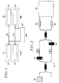
- the device is shown schematically in Figure 2 attached. He understands a single photon 40 source, an interferometer Symmetrical Mach-Zehnder 41 including a modulator phase 42 specific to Alice and a phase modulator 52 Bob's own. At the exit of the interferometer we find two single photon detectors 61, 62 and a circuit 64 of decryption and counting.
- This device works in the way next: Alice and Bob introduce by modulators 42 and 52, for each photon emitted by the source 40, a phase difference. Alice chooses arbitrarily which phase the bits 0 correspond to and 1. Bob determines the state of the bit sent using the two detectors 61, 62 following the second protocol for previously described measure.
- FIG. 3 Another system is therefore used for long distances, which is shown in Figure 3. It also includes a 70-photon source, a first Mach-Zehnder 80 interferometer used at the emission, with a first phase modulator 82 specific to Alice and a second Mach-Zehnder interferometer 90 used in reception with a second phase modulator 92 specific to Bob, two detectors to a photon 101, 102 and a means of decryption and of count 104.
- the two interferometers 80, 90 are connected by a channel 95, which is, in practice, a fiber optical.
- Each interferometer has, on one of its arms, an optical phase shifter 82, 92 allowing the key transmission. It is necessary, however, that signals from both arms of the same interferometer do not interfere. So you have to separate these two signals, either by using for example a delay between the two arms greater than the length of source consistency (which is, in this case, impulse), either by using a modulator acousto-optic for frequency separation the signal propagating in one of the two arms of the interferometers.
- FIG. 4 Another possible device is that which is described by US-A-5,307,410 already cited.
- the device is shown in Figure 4 attached. he includes a pulse source 110, a first Alice-specific interferometer with first blade semi-transparent 112, a first phase modulator 114 and a second semi-transparent strip 116; he also includes a second Bob-specific interferometer, with a third semi-transparent blade 118, a second phase modulator 120 and a fourth blade semi-transparent 122; the device still includes a detector with a photon 124 and finally a circuit of counting and decryption 126.
- Source 110 and arm lengths are such that the light pulses are separated by an interval greater than the length of impulses. But, unlike the device previous, the impulses propagating in the two arms of the interferometer do not have the same intensity (at because of the semi-transparent blades). So at the exit of the first interferometer, we observe two pulses 130, 132 separated by a delay ⁇ t. Pulse 130, called of reference, is that which has the classic intensity. The other pulse 132, called the signal pulse, containing on average less than one photon, has undergone phase shift controlled by Alice. At the end of the second interferometer three pulses are observed. The first, 140, is of negligible intensity. She comes from the signal pulse again attenuated.
- the second, 142 is the superposition of the first delayed (but not attenuated) signal pulse and the reference pulse attenuated and phase shifted by Bob.
- the intensity of the second pulse, 142 therefore depends both phase shifts introduced by Bob and Alice. It is it which is used to transmit the key of encryption.
- the last pulse, 144 is the part of the reference pulse which was further delayed and whose intensity is constant. It will be used for determine if the line was spied on.
- the object of the present invention is precisely to remedy these drawbacks.
- the modulation performed on transmission is an amplitude modulation, this amplitude having the form 1 + a cos ( ⁇ t + ⁇ A ) where a is the modulation rate and ⁇ the modulation pulse.
- a is the modulation rate and ⁇ the modulation pulse.
- the modulation rate is preferably chosen to be less than 0.5 and, for example, close to 0.1.
- the method of the invention is supplemented by verification operations aimed at determine if the quantum channel was spied on by a third.
- the sender and the recipient sacrifice some elements of their key, by publicly comparing, to determine any errors that will have been caused by the spy.
- the device represented in FIG. 5 comprises, on the emission side, a monochromatic source 200 (constituted for example by a semiconductor laser such as a distributed reaction laser (DFB) operating at 1 ⁇ m or at 1.5 ⁇ m), an attenuator 202, a first optical modulator 204 controlled by a carrier, the latter being produced by a generator 206, the phase ⁇ A of this carrier being adjusted by a phase shifter 208.
- the modulated optical wave is transmitted on a line 210, which can be an optical fiber. This line constitutes the quantum channel.
- the device On the reception side, the device comprises a second modulator 224, controlled by a carrier produced by a local generator 226, the phase ⁇ B of this carrier being adjusted by a phase shifter 228.
- These different electronic means are synchronized, between transmitter and receiver, firstly by a modulation frequency synchronization circuit 230, which controls the two local generators 206 and 226, and then by a phase shift synchronization circuit 240, which controls a first circuit 242 for controlling and storing the electrical phase shift ⁇ A imposed by the phase shifter 208, and a second circuit 244 for controlling and storing the electrical phase shift ⁇ B imposed by the phase shifter 228.
- a public channel 243 is used to exchange and compare the results.
- the device On the receiver side, the device includes another spectral filter 250, for example of the type Fabry-Pérot interferometer, a photon detector 252, (for example an avalanche photodiode), placed behind the spectral filter 250, a detector multiphotonic 254, for example of the photodiode type, a 256 photon counter connected to the detector with a photon 252 and a circuit 258 for control and storage photon counting.
- a photon detector 252 for example an avalanche photodiode
- a detector multiphotonic 254 for example of the photodiode type
- a 256 photon counter connected to the detector with a photon 252 and a circuit 258 for control and storage photon counting.
- the light beam emitted by the source 200 is attenuated by the adjustable attenuator 202 to obtain a low output intensity but large enough to be considered conventional.
- This attenuated beam constitutes the reference beam.
- the reference beam is modulated either in amplitude or in phase by the modulator 204. This periodic modulation is, in the simplest of cases, sinusoidal. It is produced by the local generator 206.
- the amplitude and the pulse of the optical field at the input of the modulator 204 are called Ao and ⁇ o respectively.
- this amplitude modulation brings up two modes at the two side frequencies separated by ⁇ from the initial pulse ⁇ o.
- the amplitude of these modes is Aof / 2.
- the intensity of these modes sides must be low enough so that can consider that there is only one photon. More strictly, the mean time separating two photons with the same pulsation be greater than the time interval used to transmit a bit of information. This is achieved by controlling the modulation amplitude.
- the code of the information bit is carried out by introducing a phase shift ⁇ A in the modulation signal. This offset is produced by the phase shifter 208 under the control of circuit 242.
- the amplitude of the beam at the output of the first modulator 204 becomes: A 1 ⁇ Ao (1 + f cos ( ⁇ t + ⁇ A ))
- This signal is transmitted to the second modulator 224 via optical fiber 210.
- This fiber constitutes the quantum transmission channel.
- Bob thanks to his local generator 226, modulates the optical signal received with the same amplitude. It itself introduces a phase ⁇ B thanks to the phase shifter 228.
- the amplitude at the output of the second modulator 224 is of the form: A 1 ⁇ Ao (1 + f cos ( ⁇ t + ⁇ A )) + f cos ( ⁇ t + ⁇ B )) ⁇ Ao (1 + 2 f cos (( ⁇ A - ⁇ B ) / 2) cos ( ⁇ t + ( ⁇ B + ⁇ A ) / 2)
- the intensity of the lateral modes therefore depends on the phases ⁇ A and ⁇ B introduced by the transmitter and the receiver: I ⁇ 4
- FIGS. 6B, 6C, 6D represent the respective intensities of the lateral modes according to the respective values of the phase shifts ⁇ A and ⁇ B :
- Bob uses the 250 spectral filter, which allows separate the central mode ⁇ o and the lateral modes ( ⁇ o ⁇ ⁇ ).
- the detection of the reference beam ( ⁇ o) is carried out by the conventional photodetector 254 and is necessary to confirm the presence of the transmitted bit.
- the detection of the lateral mode is carried out by the single photon detector 252.
- a spy If a spy (Eve) is present on the channel transmission, it will try to determine the state of the bit sent by Alice and send the same bit back to Bob for not be detected. For this, it will use the same procedure and the same system as Bob. To detect its presence, Alice and Bob have to sacrifice a few elements of their key by comparing them publicly (to determine the errors caused by Eve).
- Table 1 concerns the key transmission protocol.
- Table 2 summarizes the strategy used by the sender of the key (Alice).
- Table 3 illustrates the detection of the presence of a spy. Bit sent by Alice 0 1 Phase used by Alice 0 ⁇ / 2 Phase used by Bob ⁇ 3 ⁇ / 2 ⁇ 3 ⁇ / 2 Photon detected by Bob no no Yes no Yes no Bit read by Bob ? ? 0 ? 1 ? Detection announced by Bob no no Yes no Yes no Common bit no no Yes no Yes no Phase used by Alice 0 ⁇ / 2 Phase used by Eve ⁇ 3 ⁇ / 2 ⁇ 3 ⁇ / 2 Photon detected by Eve no no Yes no Yes no Phase detected by Eve ? ? 0 ?
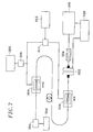
- a device according to the invention may be in accordance with the diagram in the figure 7, which relates to a montage used to demonstrate the feasibility of the process.
- the device shown includes a 300-type semiconductor laser distributed reaction (DFB) controlled by a temperature circuit 302.
- Phase modulator 304 is controlled by a generator 306 whose output is amplified by an amplifier 308.
- the output of amplifier 308 is directly applied to the modulator 304, but is also applied to a phase shifter 310 controlled by a circuit 312.
- the modulator 320 of the receiver is controlled by the phase shifter 310.
- the two modulators 304 and 320 therefore work with an adjustable phase shift ⁇ .
- a spectrum analyzer 322, of the Fabry-Pérot type, is controlled by a ramp generator 328.
- the analyzer 322 is followed by a detector 324 connected to a oscilloscope 326.
- Figure 8 shows the simulation of the intensity (I) at the exit of Fabry-Pérot 322 in function of the displacement (D) of the mirrors when one modulators is in operation.
- FIG. 9 shows the intensity ratio (IR) between the central mode and the first two lateral modes as a function of the modulation amplitude a .
- This relationship is defined by the quantity [J 1 (a) / J o (a)] 2 where J 1 () and J o () are the Bessel functions of order 1 and 0 and at the modulation amplitude.
- J 1 () and J o () are the Bessel functions of order 1 and 0 and at the modulation amplitude.
- This figure shows that the modulation rate must be low, more exactly less than or equal to 0.1 (in reduced units). We can notice that at low modulation rate, the intensity of the other modes becomes negligible (1.5.10 6 times less than order 0).
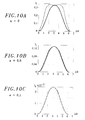
- FIGS. 10A, 10B, 10C represent.
- Figures 10A, 10B and 10C also show, in solid lines, the curve (1 - cos ⁇ ).
Abstract
Description
- l'état d'une particule élémentaire (par exemple l'état de polarisation d'un photon), ne peut être déterminé que si la mesure est réalisée dans la même base que celle qui a été utilisée pour préparer cet état (par exemple, on ne pourra pas déterminer l'état d'un photon polarisé circulairement, à droite ou à gauche, en mesurant cet état dans une base de polarisation linéaire) ;
- toute mesure projette le système étudié dans un état propre de la base utilisée pour effectuer cette mesure ; il n'est plus possible alors de connaítre l'état dans lequel était le système avant la mesure si la base n'est pas la même ; ainsi, mesurer la polarisation linéaire d'un photon préparé dans un état de polarisation circulaire produit une perte de connaissance de son état initial de polarisation.
- le protocole à quatre états : Alice utilise deux bases non orthogonales entre elles, formées par deux états orthogonaux. Bob utilise aléatoirement une des deux bases pour mesurer l'état du photon envoyé par Alice. Ce protocole a été proposé par S.J.D. PHOENIX et P.D. TOWNSEND dans l'article intitulé "Quantum Cryptography and Secure Optical Communications" publié dans la "revue BT Techn. Journ"., 11, 2, pp 65-75, 1993 ;
- le protocole à deux états : Alice utilise seulement deux états non orthogonaux d'un photon pour coder son information. Ce protocole est décrit dans le document US-A-5,307,410.
- un expéditeur émet une séquence de photons en choisissant aléatoirement, pour chaque photon, un état parmi deux états déterminés, chaque photon constituant ainsi un code pour un bit d'information,
- un destinataire détecte les photons en choisissant aléatoirement une base de mesure parmi deux bases déterminées,
- le destinataire indique, par un canal public, à l'expéditeur, quels sont les photons qu'il a détectés, mais sans révéler quelle base il a utilisée,
le procédé de l'invention est caractérisé par le fait que :
- A) l'expéditeur :
- a) engendre un faisceau lumineux ayant une certaine pulsation (wo) et une certaine intensité,
- b) produit un premier signal électrique de modulation ayant une certaine pulsation (Ω),
- c) donne à ce premier signal électrique de modulation une première phase (ØA) choisie aléatoirement parmi deux valeurs, le code de chaque bit étant ainsi déterminé par cette première phase (ØA),
- d) module le faisceau lumineux par le premier signal électrique, cette modulation faisant apparaítre, dans le faisceau lumineux modulé, un mode central (wo) et au moins deux modes latéraux (wo ± Ω),
- e) atténue l'intensité du faisceau lumineux de telle sorte que l'intensité des modes latéraux soit suffisamment faible pour qu'il n'existe qu'un seul photon dans les modes latéraux, les photons associés aux bits d'information devant constituer la clé de cryptage étant ainsi les photons transmis dans les modes latéraux, et non dans le mode central,
- la figure 1, déjà décrite, est un diagramme général d'un dispositif de distribution quantique de clé de cryptage ;
- la figure 2, déjà décrite, illustre un dispositif de distribution quantique de clé utilisant un codage de phase optique ;
- la figure 3, déjà décrite, illustre un dispositif de distribution quantique de clé sur une longue distance utilisant un codage de phase optique ;
- la figure 4, déjà décrite, illustre un dispositif de distribution quantique de clé de cryptage à deux états non orthogonaux ;
- la figure 5 montre un dispositif de distribution quantique de clé conforme à l'invention ;
- la figure 6A, montre la densité spectrale d'énergie observée à la sortie du premier modulateur et les figures 6B, 6C, 6D la densité spectrale d'énergie observée à la sortie du second modulateur en fonction du déphasage : pour 6B le déphasage est nul, pour 6C le déphasage est égal à π, et pour 6D le déphasage est égal à π/2 ;
- la figure 7 illustre un montage utilisé pour vérifier la faisabilité du procédé ;
- la figure 8 montre les variations du signal de sortie d'un analyseur de spectre constitué par un Fabry-Pérot en fonction du déplacement de l'un de ses miroirs ;
- la figure 9 montre le rapport entre l'intensité du mode central et l'intensité des deux premiers modes latéraux en fonction de l'amplitude de modulation ;
- les figures 10A, 10B, 10C montrent les variations de l'intensité du premier mode en fonction du déphasage pour différentes amplitudes de modulation : pour 10A l'amplitude de modulation est égale à 2 ; pour 10B l'amplitude est égale à 0,8 ; 10C : l'amplitude est égale à 0,1 ;
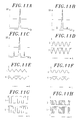
- les figures 11A, 11B, 11C montrent la densité spectrale observée à la sortie du Fabry-Pérot avec, respectivement, un déphasage de 0, de π/2 et de π ; les figures 11D, 11E, 11F, 11G, 11H les tensions de commande (en bas) et les variations d'intensité (en haut) du premier mode de modulation sélectionné par le Fabry-Pérot, en fonction du déphasage (11D : déphasage de 0 à π) (11E et 11F : déphasage voisin de π/4) (11G, 11H : le déphasage prend deux valeurs, 0 et π/2).
| Bit envoyé par Alice | 0 | 1 | ||||
| Phase utilisée par Alice | 0 | π/2 | ||||
| Phase utilisée par Bob | π | 3 π/2 | π | 3 π/2 | ||
| Photon détecté par Bob | non | non | oui | non | oui | non |
| Bit lu par Bob | ? | ? | 0 | ? | 1 | ? |
| Détection annoncée par Bob | non | non | oui | non | oui | non |
| Bit commun | non | non | oui | non | oui | non |
| Phase utilisée par Alice | 0 | π/2 | ||||||||
| Phase utilisée par Eve | π | 3π/2 | π | 3π/2 | ||||||
| Photon détectée par Eve | non | non | oui | non | oui | non | ||||
| Phase détectée par Eve | ? | ? | 0 | ? | π/2 | ? | ||||
| Phase choisie par Eve pour falsifier le signal | 0 | π/2 | 0 | π/2 | 0 | 0 | π/2 | 3π/2 | 0 | 3π/2 |
| Détection de l'espion | non | oui | non | oui | non | oui | non | non | oui | non |
| Phase utilisée par Alice | 0 | π/2 | ||||
| Phase choisie par Eve pour falsifier le signal | π/2 | 0 | ||||
| Phase utilisée par Bob | π | 3 π/2 | π | 3 π/2 | ||
| Photon détecté par Bob | non | non | oui | non | oui | non |
| Détection de l'espion | oui | non | non | non | oui | non |
- le laser DFB utilisé a une largeur spectrale d'environ 1 MHz et sa longueur d'onde est d'environ 1,5582 µm ;
- la tension de commande du modulateur 304 va de 7 V à 15 V ;
- l'amplificateur 308 est à haute fréquence (10 MHz à 1GHz) et son gain en puissance est de 40 dB ;
- le déphasage électrique entre la voie directe et la voie déphasée est produit par le déphaseur 310 commandé en tension (360°/12V) ; on travaille avec une modulation électrique de 300 MHz.
- le Fabry-Pérot 322 est formé de deux miroirs plans ; il est piloté par un générateur de rampe qui permet de faire varier la position d'un miroir et donc de retrouver le spectre ; le coefficient de réflexion des miroirs est de 0,95 ; les miroirs sont espacés de 15cm de manière à obtenir la résolution maximale ; on obtient une finesse de 60 avec un pouvoir de résolution Δλ/λ = 1,18.10-7, soit une largeur de 16 Mhz ; cette résolution est suffisante pour résoudre les bandes latérales de modulation qui apparaissent quand on utilise les modulateurs électro-optiques, car la fréquence de modulation est de 300 MHz ;
- les modulateurs 304 et 320 peuvent être des modulateurs de phase électro-optiques intégrés sur niobate de lithium ; ces modulateurs ont respectivement une bande passante de 500 MHz et 1 GHz ; l'atténuation provoquée par les modulateurs est de l'ordre de 10dB ; la fréquence de modulation est de 300 MHz.
- Fig. 11A, 11B, 11C : densité spectrale DS observée à la sortie du Fabry-Pérot 322 avec, respectivement, un déphasage de 0, de π/2 et de π entre le signal de commande des deux modulateurs 304 et 322,
- Fig. 11D, 11E, 11F, 11G, 11H : signaux inférieurs : tension de commande V provoquant une variation de déphasage entre les signaux de commande des deux modulateurs signaux supérieurs : variation d'intensité I ; du premier mode de modulation sélectionné par le Fabry-Pérot correspondant au déphasage,
- Fig. 11D : le déphasage varie continûment de manière linéaire de 0 à π,
- Fig. 11E et 11F : le déphasage varie continûment et faiblement autour de π/4 : de manière linéaire (11E) et sinusoïdale (11F),
- Fig. 11G et 11H : le déphasage varie suivant deux états 0 et π/2 : 11G signal périodique, 11H signal apériodique.
Claims (7)
- Procédé de distribution quantique de clé de cryptage dans lequel :l'expéditeur et le destinataire retiennent les bits pour lesquels les photons ont été détectés comme constituant une clé de cryptage entre eux,un expéditeur émet une séquence de photons en choisissant aléatoirement, pour chaque photon, un état parmi deux états déterminés, chaque photon constituant ainsi un code pour un bit d'information,un destinataire détecte les photons en choisissant aléatoirement une base de mesure parmi deux bases déterminées,le destinataire indique, par un canal public, à l'expéditeur, quels sont les photons qu'il a détectés, mais sans révéler quelle base il a utilisée,
ce procédé étant caractérisé par le fait que :l'expéditeur et le destinataire retiennent alors, comme clé de cryptage, l'ensemble des bits correspondant aux photons détectés.A) l'expéditeur :a) engendre un faisceau lumineux ayant une certaine pulsation (wo) et une certaine intensité,b) produit un premier signal électrique de modulation,c) donne à ce premier signal électrique de modulation une première phase (ØA) choisie aléatoirement parmi deux valeurs déterminées, le code de chaque bit étant ainsi déterminé par cette première phase (ØA),d) module le faisceau lumineux par ce premier signal électrique, cette modulation faisant apparaítre, dans le faisceau lumineux modulé, un mode central (wo) et au moins deux modes latéraux (wo ± Ω),e) atténue l'intensité du faisceau lumineux de telle sorte que l'intensité des modes latéraux soit suffisamment faible pour qu'il n'existe qu'un seul photon dans les modes latéraux, les photons associés aux bits d'information devant constituer la clé de cryptage étant ainsi les photons transmis dans les modes latéraux, et non dans le mode central,B) le destinataire :a) produit un second signal électrique de modulation en synchronisme avec le premier signal électrique de modulation utilisé à l'émission,b) donne au second signal électrique une seconde phase (ØB) choisie aléatoirement parmi deux valeurs déterminées, ces deux valeurs étant différentes des deux valeurs déterminées choisies à l'émission pour la première phase (ØA),c) module le faisceau lumineux reçu par le second signal électrique,d) sépare optiquement le mode central reçu et les modes latéraux,e) détecte, dans l'un des modes latéraux, la présence d'un photon, cette détection dépendant de la différence de phase () entre le premier déphasage (ØA) choisi par l'expéditeur et le second déphasage (ØB) choisi par le destinataire,f) communique à l'expéditeur, par le canal public, quels sont les photons qu'il a détectés, mais sans révéler les valeurs du second déphasage (ØB) qu'il a utilisées, - Procédé selon la revendication 1, dans lequel la modulation est une modulation d'amplitude ou de fréquence avec un certain taux de modulation (a).
- Procédé selon la revendication 2, dans lequel le taux de modulation est inférieur à environ 0,5.
- Procédé selon la revendication 3, dans lequel le taux de modulation est voisin de 0,1.
- Dispositif pour la mise en oeuvre du procédé selon la revendication 1, caractérisé par le fait qu'il comprend :et, côté expéditeur et côté destinataire, des moyens (242,244) pour retenir comme clé de cryptage, l'ensemble des bits correspondant aux photons détectés.A) côté expéditeur :a) une source lumineuse (200,300) apte à engendrer un faisceau lumineux ayant une certaine pulsation (wo) et une certaine intensité,b) des moyens (206,306) pour produire un premier signal électrique de modulation,c) des moyens (208,308) pour donner à ce premier signal électrique de modulation une première phase (ØA) choisie aléatoirement parmi deux valeurs déterminées, le code de chaque bit étant ainsi déterminé par cette première phase (ØA),d) des moyens (204,304) pour moduler le faisceau lumineux par ce premier signal électrique, cette modulation faisant apparaítre, dans le faisceau lumineux modulé, un mode central (wo) et au moins deux modes latéraux (wo ± Ω),e) un atténuateur (202) de l'intensité du faisceau lumineux, de telle sorte que l'intensité des modes latéraux soit suffisamment faible pour qu'il n'existe qu'un seul photon dans les modes latéraux, les photons associés aux bits d'information devant constituer la clé de cryptage étant ainsi les photons transmis dans les modes latéraux, et non dans le mode central,B) côté destinataire :a) des moyens (226) pour produire un second signal électrique de modulation en synchronisme avec le premier signal électrique de modulation utilisé à l'émission,b) des moyens (228,310,312) pour donner au second signal électrique une seconde phase (ØB) choisie aléatoirement parmi deux valeurs déterminées, ces deux valeurs étant différentes des deux valeurs déterminées choisies à l'émission pour la première phase (ØA),c) des moyens (224,320) pour moduler le faisceau lumineux reçu par le second signal électrique,d) un analyseur (250,322) pour séparer optiquement le mode central reçu et les modes latéraux,e) un photodétecteur (252,324) recevant l'un des modes latéraux, le signal délivré par ce photodétecteur dépendant de la différence de phase (Ø) entre le premier déphasage (ØA) choisi par l'expéditeur et le second déphasage (ØB) choisi par le destinataire,f) des moyens (243) pour communiquer à l'expéditeur, par un canal public, quels sont les photons qui ont été détectés, mais sans révéler les valeurs du second déphasage (ØB) utilisées,
- Dispositif selon la revendication 5, dans lequel la source lumineuse (200,300) est un laser à semi-conducteur.
- Dispositif selon la revendication 5, comprenant des moyens de multidistribution de clefs de cryptage utilisant des moyens de multiplexage en longueur d'onde.
Applications Claiming Priority (2)
| Application Number | Priority Date | Filing Date | Title |
|---|---|---|---|
| FR9705573A FR2763193B1 (fr) | 1997-05-06 | 1997-05-06 | Procede et dispositif de distribution quantique de cle de cryptage |
| FR9705573 | 1997-05-06 |
Publications (2)
| Publication Number | Publication Date |
|---|---|
| EP0877508A1 true EP0877508A1 (fr) | 1998-11-11 |
| EP0877508B1 EP0877508B1 (fr) | 2007-08-01 |
Family
ID=9506628
Family Applications (1)
| Application Number | Title | Priority Date | Filing Date |
|---|---|---|---|
| EP98401079A Expired - Lifetime EP0877508B1 (fr) | 1997-05-06 | 1998-05-04 | Procédé et dispositif de distribution quantique de clé de cryptage |
Country Status (4)
| Country | Link |
|---|---|
| US (1) | US6272224B1 (fr) |
| EP (1) | EP0877508B1 (fr) |
| DE (1) | DE69838159D1 (fr) |
| FR (1) | FR2763193B1 (fr) |
Cited By (4)
| Publication number | Priority date | Publication date | Assignee | Title |
|---|---|---|---|---|
| FR2818061A1 (fr) * | 2000-12-12 | 2002-06-14 | France Telecom | Systeme pour la transmission optique securisee de code binaire |
| EP1780934A2 (fr) * | 2005-10-31 | 2007-05-02 | Fujitsu Ltd. | Système, appareil et méthode de cryptage et décryptage de cryptographique quantique |
| CN112461380A (zh) * | 2020-10-15 | 2021-03-09 | 国开启科量子技术(北京)有限公司 | 一种脉冲光相位随机性检测装置及方法 |
| CN114584224A (zh) * | 2022-04-28 | 2022-06-03 | 杭州慧明量子通信技术有限公司 | 一种量子密钥分发相位编码装置 |
Families Citing this family (54)
| Publication number | Priority date | Publication date | Assignee | Title |
|---|---|---|---|---|
| JP4038783B2 (ja) * | 1998-09-24 | 2008-01-30 | 独立行政法人科学技術振興機構 | 量子暗号通信システム及び量子暗号通信方法 |
| DE10009209A1 (de) * | 2000-02-26 | 2001-09-06 | Deutsche Telekom Ag | Vorrichtung zur Erzeugung, Addition und Subtraktion digitaler Folgen optischer Pulse und Verfahren zur sicheren Übertragung von Nachrichten |
| KR100327494B1 (ko) * | 2000-03-24 | 2002-03-15 | 윤종용 | 다중 접근 방식을 이용한 보안 통신 시스템에서의 키 동의방법 |
| FR2816780B1 (fr) * | 2000-11-10 | 2003-01-31 | Thomson Csf | Procede et systeme de transmission par cryptographie quantique |
| FR2816772B1 (fr) * | 2000-11-10 | 2003-01-31 | Thomson Csf | Procede et systeme de transmission par cryptographie quantique |
| US7184555B2 (en) * | 2001-04-11 | 2007-02-27 | Magiq Technologies, Inc. | Quantum computation |
| US8068741B2 (en) * | 2001-04-11 | 2011-11-29 | Magiq Technologies, Inc. | Polarization to phase converter |
| WO2002089396A1 (fr) * | 2001-05-01 | 2002-11-07 | Magiq Technologies, Inc. | Systeme de cle quantique et procede associe |
| US7113967B2 (en) | 2001-05-29 | 2006-09-26 | Magiq Technologies, Inc | Efficient quantum computing operations |
| WO2003058865A1 (fr) * | 2001-12-21 | 2003-07-17 | Magiq Technologies, Inc. | Decouplage de la correction d'erreurs a partir de l'amplification de la confidentialite dans une distribution de cle de quantum |
| JP4462806B2 (ja) * | 2002-02-22 | 2010-05-12 | 日本電気株式会社 | 量子暗号鍵配布システム |
| US7403623B2 (en) * | 2002-07-05 | 2008-07-22 | Universite Libre De Bruxelles | High-rate quantum key distribution scheme relying on continuously phase and amplitude-modulated coherent light pulses |
| US7333611B1 (en) | 2002-09-27 | 2008-02-19 | Northwestern University | Ultra-secure, ultra-efficient cryptographic system |
| US20060222180A1 (en) * | 2002-10-15 | 2006-10-05 | Elliott Brig B | Chip-scale transmitter for quantum cryptography |
| US20060018475A1 (en) * | 2003-02-07 | 2006-01-26 | Magiq Technologies, Inc. | Kd systems with robust timing |
| US7227955B2 (en) * | 2003-02-07 | 2007-06-05 | Magiq Technologies, Inc. | Single-photon watch dog detector for folded quantum key distribution system |
| US7609382B2 (en) * | 2003-05-23 | 2009-10-27 | General Dynamics Advanced Information System, Inc, | System and method of detecting entangled photons |
| US7539308B2 (en) * | 2003-05-23 | 2009-05-26 | General Dynamics Advanced Information Systems, Inc. | Quantum steganography |
| GB2404103B (en) * | 2003-07-15 | 2005-06-29 | Toshiba Res Europ Ltd | A quantum communication system |
| US7847234B2 (en) | 2003-08-06 | 2010-12-07 | The United States Of America As Represented By The Secretary Of The Army | Method and system for observing a subject at a first location based upon quantum properties measured at a second location |
| US8242428B2 (en) * | 2007-12-06 | 2012-08-14 | The United States Of America As Represented By The Secretary Of The Army | Method and system for lidar using spatial information from a light source in combination with nonspatial information influenced by the subject to derive an image |
| US7536012B1 (en) | 2003-08-06 | 2009-05-19 | The United States Of America As Represented By The Secretary Of The Army | Entangled quantum communications and quantum imaging |
| GB2405294B (en) * | 2003-08-18 | 2006-08-09 | Toshiba Res Europ Ltd | A quantum communication system and a receiver for a quantum communication system |
| US7831048B2 (en) * | 2003-12-17 | 2010-11-09 | General Dynamics Advanced Information Systems, Inc. | Secure quantum key distribution using entangled photons |
| EP1783931B1 (fr) * | 2004-07-12 | 2009-02-18 | Mitsubishi Electric Corporation | Appareil de détection photonique et système de communication optique |
| WO2006011215A1 (fr) * | 2004-07-29 | 2006-02-02 | Mitsubishi Denki Kabushiki Kaisha | Système de gestion de statut de placement, appareil de lecture de radio tags, et appareil de gestion |
| US7822342B1 (en) | 2004-11-15 | 2010-10-26 | The United States Of America As Represented By The Secretary Of The Navy | Secure quantum optical communications system and method |
| US7706694B2 (en) * | 2005-07-25 | 2010-04-27 | General Dynamics Advanced Information Systems, Inc. | Processor for entangled complex signals |
| FR2889320B1 (fr) * | 2005-07-27 | 2007-10-26 | Smartquantum Sa | Systeme de transmission optique et dispositif de reception d'un signal optique |
| GB2430124B (en) * | 2005-09-09 | 2008-01-09 | Toshiba Res Europ Ltd | Quantum communication system |
| US7809143B2 (en) * | 2005-10-24 | 2010-10-05 | Magiq Technologies, Inc. | QKD system with synchronization channel verification |
| US20070130455A1 (en) * | 2005-12-06 | 2007-06-07 | Elliott Brig B | Series encryption in a quantum cryptographic system |
| US20070133798A1 (en) * | 2005-12-14 | 2007-06-14 | Elliott Brig B | Quantum cryptography on a multi-drop optical network |
| US8082443B2 (en) * | 2006-01-09 | 2011-12-20 | Bbnt Solutions Llc. | Pedigrees for quantum cryptography |
| US7248695B1 (en) * | 2006-02-10 | 2007-07-24 | Magiq Technologies, Inc. | Systems and methods for transmitting quantum and classical signals over an optical network |
| US20070291811A1 (en) * | 2006-05-26 | 2007-12-20 | Conti Ralph S | Entangled Photon Source |
| GB2441364B (en) * | 2006-08-31 | 2009-02-11 | Toshiba Res Europ Ltd | A quantum communication system and method |
| FR2906424B1 (fr) * | 2006-09-25 | 2008-11-28 | Centre Nat Rech Scient | Systeme et procede pour la transmission securisee de code binaire par codage en phase et en intensite |
| US8811763B2 (en) | 2007-12-06 | 2014-08-19 | The United States Of America As Represented By The Secretary Of The Army | Method and system for producing image frames using quantum properties |
| JP2011130120A (ja) * | 2009-12-16 | 2011-06-30 | Sony Corp | 量子公開鍵暗号システム、鍵生成装置、暗号化装置、復号装置、鍵生成方法、暗号化方法、及び復号方法 |
| JP5682212B2 (ja) * | 2010-10-06 | 2015-03-11 | ソニー株式会社 | 量子暗号通信装置と量子暗号通信方法および量子暗号通信システム |
| RU2454810C1 (ru) * | 2010-11-24 | 2012-06-27 | Федеральное государственное бюджетное образовательное учреждение высшего профессионального образования "Санкт-Петербургский национальный исследовательский университет информационных технологий, механики и оптики" ("НИУ ИТМО") | Устройство квантовой рассылки криптографического ключа на поднесущей частоте модулированного излучения |
| US9184912B2 (en) * | 2012-04-17 | 2015-11-10 | The Boeing Company | Secure quantum authentication system |
| GB2514134B (en) * | 2013-05-14 | 2016-05-25 | Toshiba Res Europe Ltd | A signal manipulator for a quantum communication system |
| CN106411521B (zh) * | 2015-07-31 | 2020-02-18 | 阿里巴巴集团控股有限公司 | 用于量子密钥分发过程的身份认证方法、装置及系统 |
| CN105337730B (zh) * | 2015-11-19 | 2018-08-24 | 山西大学 | 基于相位编码qkd系统的单光子偏振控制方法及装置 |
| RU2692431C1 (ru) * | 2018-07-03 | 2019-06-24 | Федеральное государственное образовательное учреждение высшего образования "Казанский национальный исследовательский технический университет им. А.Н. Туполева - КАИ" | Устройство квантовой рассылки криптографического ключа с частотным кодированием |
| RU2747164C1 (ru) * | 2019-11-12 | 2021-04-28 | Общество с ограниченной ответственностью "СМАРТС-Кванттелеком" | Устройство квантовой рассылки ключа на боковых частотах, устойчивое к поляризационным искажениям сигнала в волоконно-оптических линиях связи |
| RU2750810C1 (ru) * | 2020-01-22 | 2021-07-05 | Общество с ограниченной ответственностью "СМАРТС-Кванттелеком" | Устройство квантовой коммуникации на боковых частотах с регистрацией излучения на центральной частоте |
| RU2744509C1 (ru) * | 2020-01-22 | 2021-03-11 | Общество с ограниченной ответственностью "Кванттелеком" | Устройство квантовой коммуникации на боковых частотах с увеличенным дискретным набором фаз модулирующих сигналов |
| RU2758709C1 (ru) * | 2020-09-15 | 2021-11-01 | Общество с ограниченной ответственностью "СМАРТС-Кванттелеком" | Устройство квантовой рассылки симметричной битовой последовательности на поднесущей частоте модулированного излучения с гомодинным методом приема |
| RU2758711C1 (ru) * | 2020-09-15 | 2021-11-01 | Общество с ограниченной ответственностью "СМАРТС-Кванттелеком" | Устройство квантовой рассылки симметричной битовой последовательности на поднесущей частоте модулированного излучения с гетеродинным методом приема |
| RU2758708C1 (ru) * | 2020-09-15 | 2021-11-01 | Общество с ограниченной ответственностью "СМАРТС-Кванттелеком" | Устройство квантовой рассылки симметричной битовой последовательности на поднесущей частоте модулированного излучения с двойным гомодинным методом приема |
| CN114499685B (zh) * | 2022-01-28 | 2023-10-20 | 中国科学技术大学 | 信号处理方法、发射端系统、电子设备及存储介质 |
Citations (1)
| Publication number | Priority date | Publication date | Assignee | Title |
|---|---|---|---|---|
| WO1996006491A1 (fr) * | 1994-08-18 | 1996-02-29 | British Telecommunications Public Limited Company | Cryptographie quantique |
Family Cites Families (9)
| Publication number | Priority date | Publication date | Assignee | Title |
|---|---|---|---|---|
| US5243649A (en) * | 1992-09-29 | 1993-09-07 | The Johns Hopkins University | Apparatus and method for quantum mechanical encryption for the transmission of secure communications |
| AU674198B2 (en) * | 1992-12-24 | 1996-12-12 | British Telecommunications Public Limited Company | System and method for key distribution using quantum cryptography |
| US5339182A (en) * | 1993-02-19 | 1994-08-16 | California Institute Of Technology | Method and apparatus for quantum communication employing nonclassical correlations of quadrature-phase amplitudes |
| US5307410A (en) * | 1993-05-25 | 1994-04-26 | International Business Machines Corporation | Interferometric quantum cryptographic key distribution system |
| CA2169746C (fr) * | 1993-09-09 | 1999-11-16 | Simon James Daniel Phoenix | Methode de distribution de cles utilisant la cryptographie quantique |
| GB9320793D0 (en) * | 1993-10-08 | 1993-12-08 | Secr Defence | Cryptographic receiver |
| US5515438A (en) * | 1993-11-24 | 1996-05-07 | International Business Machines Corporation | Quantum key distribution using non-orthogonal macroscopic signals |
| US5953421A (en) * | 1995-08-16 | 1999-09-14 | British Telecommunications Public Limited Company | Quantum cryptography |
| US5966224A (en) * | 1997-05-20 | 1999-10-12 | The Regents Of The University Of California | Secure communications with low-orbit spacecraft using quantum cryptography |
-
1997
- 1997-05-06 FR FR9705573A patent/FR2763193B1/fr not_active Expired - Fee Related
-
1998
- 1998-04-21 US US09/063,413 patent/US6272224B1/en not_active Expired - Fee Related
- 1998-05-04 DE DE69838159T patent/DE69838159D1/de not_active Expired - Lifetime
- 1998-05-04 EP EP98401079A patent/EP0877508B1/fr not_active Expired - Lifetime
Patent Citations (1)
| Publication number | Priority date | Publication date | Assignee | Title |
|---|---|---|---|---|
| WO1996006491A1 (fr) * | 1994-08-18 | 1996-02-29 | British Telecommunications Public Limited Company | Cryptographie quantique |
Non-Patent Citations (1)
| Title |
|---|
| KLYSHKO D N: "Quantum cryptography using multicolored or multidirectional photons", PHYSICS LETTERS A, 10 MARCH 1997, ELSEVIER, NETHERLANDS, vol. 227, no. 1-2, ISSN 0375-9601, pages 1 - 4, XP002052966 * |
Cited By (9)
| Publication number | Priority date | Publication date | Assignee | Title |
|---|---|---|---|---|
| FR2818061A1 (fr) * | 2000-12-12 | 2002-06-14 | France Telecom | Systeme pour la transmission optique securisee de code binaire |
| WO2002049267A1 (fr) * | 2000-12-12 | 2002-06-20 | France Telecom | Systeme pour la transmission optique securisee de code binaire |
| US7266304B2 (en) | 2000-12-12 | 2007-09-04 | France Telecom | System for secure optical transmission of binary code |
| EP1780934A2 (fr) * | 2005-10-31 | 2007-05-02 | Fujitsu Ltd. | Système, appareil et méthode de cryptage et décryptage de cryptographique quantique |
| EP1780934A3 (fr) * | 2005-10-31 | 2007-07-11 | Fujitsu Ltd. | Système, appareil et méthode de cryptage et décryptage de cryptographique quantique |
| US7471790B2 (en) | 2005-10-31 | 2008-12-30 | Fujitsu Limited | Encryption method, cryptogram decoding method, encryptor, cryptogram decoder, and communication system |
| CN112461380A (zh) * | 2020-10-15 | 2021-03-09 | 国开启科量子技术(北京)有限公司 | 一种脉冲光相位随机性检测装置及方法 |
| CN112461380B (zh) * | 2020-10-15 | 2021-09-24 | 国开启科量子技术(北京)有限公司 | 一种脉冲光相位随机性检测装置及方法 |
| CN114584224A (zh) * | 2022-04-28 | 2022-06-03 | 杭州慧明量子通信技术有限公司 | 一种量子密钥分发相位编码装置 |
Also Published As
| Publication number | Publication date |
|---|---|
| EP0877508B1 (fr) | 2007-08-01 |
| US6272224B1 (en) | 2001-08-07 |
| FR2763193A1 (fr) | 1998-11-13 |
| DE69838159D1 (de) | 2007-09-13 |
| FR2763193B1 (fr) | 1999-06-18 |
Similar Documents
| Publication | Publication Date | Title |
|---|---|---|
| EP0877508B1 (fr) | Procédé et dispositif de distribution quantique de clé de cryptage | |
| EP1825633B1 (fr) | Systeme de distribution quantique de cle de cryptage a variables continues | |
| EP1342337B1 (fr) | Systeme pour la transmission optique securisee de code binaire | |
| EP0783215B1 (fr) | Système de transmission optique mettant en oeuvre un cryptage par chaos déterministe | |
| JP3317352B2 (ja) | 光通信システム | |
| FR2920550A1 (fr) | Emetteur optique et son procede de commande. | |
| EP0963064A1 (fr) | Dispositif pour l'émission ou la réception d'un signal crypté par chaos déterministe | |
| CA2247186A1 (fr) | Dispositif de compensation de la dispersion de polarisation dans un systeme de transmission optique | |
| GB2405294A (en) | Receiver for a quantum cryptography communication system | |
| JP2000511016A (ja) | 偏波に感応しない量子暗号用の方法および装置 | |
| Merolla et al. | Quantum cryptographic device using single-photon phase modulation | |
| EP2067298B1 (fr) | Système et procédé pour la transmission sécurisée de code binaire par codage en phase et en intensité | |
| GB2602353A (en) | Optical system and method | |
| FR2719957A1 (fr) | Procédé pour la transmission d'informations codées sous forme binaire par un train de solitons. | |
| EP0381102B1 (fr) | Réseau de communication sur fibres optiques avec multiplexage en fréquence | |
| WO2007012730A2 (fr) | Système de transmission optique et dispositif de réception d'un signal optique | |
| EP1005192A1 (fr) | Dispositif de cryptage quantique | |
| FR3125658A1 (fr) | Système de communication quantique par photons intriqués | |
| WO2021043891A1 (fr) | Procede de transmission securisee de sequences d'etats quantiques entre plusieurs participants en ligne sur un canal de communication quantique | |
| FR2681996A1 (fr) | Procede de reperage de frequence optique et reseau de communication a canaux frequentiels appliquant ce procede. | |
| FR3136328A1 (fr) | Système et procédé de détermination de clés de cryptage utilisant l'encodage de phase d'un signal | |
| EP3785382B1 (fr) | Dispositif de traitement reconfigurable pour les communications quantiques | |
| GRUENENFELDER | Performance, Security and Network Integration of Simplified BB84 Quantum Key Distribution | |
| Francesconi et al. | Scalable Implementation of Temporal and Phase Encoding QKD with Phase‐Randomized States | |
| EP3200363A1 (fr) | Système d'échantillonnage optique linéaire et de détection cohérente d'un signal optique |
Legal Events
| Date | Code | Title | Description |
|---|---|---|---|
| PUAI | Public reference made under article 153(3) epc to a published international application that has entered the european phase |
Free format text: ORIGINAL CODE: 0009012 |
|
| AK | Designated contracting states |
Kind code of ref document: A1 Designated state(s): DE GB |
|
| AX | Request for extension of the european patent |
Free format text: AL;LT;LV;MK;RO;SI |
|
| 17P | Request for examination filed |
Effective date: 19990417 |
|
| AKX | Designation fees paid |
Free format text: DE GB |
|
| GRAP | Despatch of communication of intention to grant a patent |
Free format text: ORIGINAL CODE: EPIDOSNIGR1 |
|
| GRAS | Grant fee paid |
Free format text: ORIGINAL CODE: EPIDOSNIGR3 |
|
| GRAA | (expected) grant |
Free format text: ORIGINAL CODE: 0009210 |
|
| AK | Designated contracting states |
Kind code of ref document: B1 Designated state(s): DE GB |
|
| REG | Reference to a national code |
Ref country code: GB Ref legal event code: FG4D Free format text: NOT ENGLISH |
|
| REF | Corresponds to: |
Ref document number: 69838159 Country of ref document: DE Date of ref document: 20070913 Kind code of ref document: P |
|
| GBT | Gb: translation of ep patent filed (gb section 77(6)(a)/1977) |
Effective date: 20070905 |
|
| PLBE | No opposition filed within time limit |
Free format text: ORIGINAL CODE: 0009261 |
|
| STAA | Information on the status of an ep patent application or granted ep patent |
Free format text: STATUS: NO OPPOSITION FILED WITHIN TIME LIMIT |
|
| 26N | No opposition filed |
Effective date: 20080506 |
|
| PG25 | Lapsed in a contracting state [announced via postgrant information from national office to epo] |
Ref country code: DE Free format text: LAPSE BECAUSE OF FAILURE TO SUBMIT A TRANSLATION OF THE DESCRIPTION OR TO PAY THE FEE WITHIN THE PRESCRIBED TIME-LIMIT Effective date: 20071103 |
|
| PGFP | Annual fee paid to national office [announced via postgrant information from national office to epo] |
Ref country code: GB Payment date: 20100429 Year of fee payment: 13 |
|
| GBPC | Gb: european patent ceased through non-payment of renewal fee |
Effective date: 20110504 |
|
| PG25 | Lapsed in a contracting state [announced via postgrant information from national office to epo] |
Ref country code: GB Free format text: LAPSE BECAUSE OF NON-PAYMENT OF DUE FEES Effective date: 20110504 |