EP0880699B1 - Displacement assay on a porous membrane - Google Patents
Displacement assay on a porous membrane Download PDFInfo
- Publication number
- EP0880699B1 EP0880699B1 EP96938636A EP96938636A EP0880699B1 EP 0880699 B1 EP0880699 B1 EP 0880699B1 EP 96938636 A EP96938636 A EP 96938636A EP 96938636 A EP96938636 A EP 96938636A EP 0880699 B1 EP0880699 B1 EP 0880699B1
- Authority
- EP
- European Patent Office
- Prior art keywords
- membrane
- analyte
- labelled
- sample
- target analyte
- Prior art date
- Legal status (The legal status is an assumption and is not a legal conclusion. Google has not performed a legal analysis and makes no representation as to the accuracy of the status listed.)
- Expired - Lifetime
Links
Images


Classifications
-
- G—PHYSICS
- G01—MEASURING; TESTING
- G01N—INVESTIGATING OR ANALYSING MATERIALS BY DETERMINING THEIR CHEMICAL OR PHYSICAL PROPERTIES
- G01N33/00—Investigating or analysing materials by specific methods not covered by groups G01N1/00 - G01N31/00
- G01N33/48—Biological material, e.g. blood, urine; Haemocytometers
- G01N33/50—Chemical analysis of biological material, e.g. blood, urine; Testing involving biospecific ligand binding methods; Immunological testing
- G01N33/53—Immunoassay; Biospecific binding assay; Materials therefor
- G01N33/543—Immunoassay; Biospecific binding assay; Materials therefor with an insoluble carrier for immobilising immunochemicals
- G01N33/54366—Apparatus specially adapted for solid-phase testing
- G01N33/54386—Analytical elements
Definitions
- the present invention relates generally to assays and more specifically to displacement-type assays.
- displacement assays are faster than competitive assays.
- a displacement assay generally provides a smaller signal than a competitive assay.
- the available binding sites of the antibody are saturated or nearly saturated with labelled analyte before the unlabelled analyte is added. Since equilibrium (with labelled analyte and unlabelled analyte continually binding, releasing and competing with each other for rebinding to the available binding sites on the antibody in a steady state) has not been achieved, most of the labelled analyte in a displacement assay remains bound to the antibody and unable to provide a signal.
- the relatively small signal provided by the displacement assay places an additional value on assuring the consistency of assay conditions.
- the bead-containing columns described in USP 5,183,740 for displacement assays must be carefully stored, prepared, and loaded to assure chemical and physical consistency (i.e., porosity, avoidance of channeling) from test to test. The need for this careful preparation and testing increases the labor, skill, and costs needed to perform accurate displacement assays. Additionally, the problems associated with the use of bead-containing columns limit the lower detection limit for displacement assays.
- Kidwell discloses a displacement assay in which samples pass through a membrane having an antibody immobilized thereon. The binding sites of the immobilized antibody are bound to an enzymatically labelled analyte. Analyte from the sample displaces the labelled analyte, causing the labelled analyte and the remainder of the sample to pass into a superabsorbent layer. The superabsorbent layer contains a substrate for the enzymatic label and any needed indicator.
- the Kidwell patent teaches the need for a flow rate of about 0.02 ml/min and interaction times of about 1 to 5 min to assure a detectable interaction between the analyte and the antibody. In many situations, even faster results are desirable. Additionally, the Kidwell microassay card is not reusable.
- bioassays capable of detecting minute quantities of an analyte in under one minute.
- Membranes useful in the present invention are typically non-absorbent (with respect to aqueous materials) materials.
- the non-absorbent membrane assists in providing a fast flow-through rate. Additionally, the use of a non-absorbent membrane allows the membrane, once used, to be readily rinsed of sample and reused. If displacement has occurred, reloading with labelled analyte is an option.
- membranes useful in the present invention have thicknesses, exposed surface areas, and porosities that allow detection of the analyte with an interaction time of about 0.1 sec to about 30 seconds, and typically about 1 sec to about 15 seconds, between a sample suspected of containing of the analyte and the membrane having a labelled analyte of the analyte thereon.
- the pore sizes in the membrane are about 0.2-1.0 microns, and are typically about 0.45 microns. Of course, other pore sizes may be used to achieve the desired interaction time.
- the thickness and surface area of the membrane can be adjusted to provide the desired interaction time.
- any non-absorbent membrane of appropriate pore size and density of sites for immobilizing binding elements for the analyte, may be used.
- the membrane may be a polyamide (e.g., Nylon TM membranes such as Immunodyne ABC TM (a Nylon TM 6,6 membrane made by Pall Biosupport, Port Washington, New York)) or a polyvinylidine fluoride, such as Immobilon TM or Durapore TM membranes made by Millipore, Bedford, Massachusetts.
- suitable membranes include, but are not limited to, cellulose, nitrocellulose, silica fiber, aluminum oxide, and polyvinyl chloride.
- Binding elements may be immobilized on the selected membrane in any manner that assures the availability on the immobilized binding element of at least one binding site for selectively binding the labelled analyte and target analyte in an aqueous medium.
- the binding element may be immobilized either throughout the thickness of the membrane, or on only one or both surfaces thereof.
- the binding element may be any substance that can be immobilized on the membrane and that specifically binds the target analyte and its labelled analog. Binding elements include, but are not limited to, lectins, antibodies, antibiotics, and binding proteins other than antibodies and antibiotics.
- binding elements Once the binding elements have been immobilized on the membrane, their available binding sites for selectively binding with the analyte will usually be essentially saturated with a labelled analog of the analyte (denoted herein as a "labelled analyte"). Saturation of the available binding sites with the labelled analyte enhances sensitivity by assuring that the maximum number of analyte molecules will displace labelled analytes, rather than binding directly to unoccupied binding sites.
- labelled analyte labelled analog of the analyte
- the membrane is oriented in a manner with respect to sample flow that allows the sample to flow past the complex of binding element and labelled analyte on the membrane over the desired interaction time.
- the sample flows through normal to the plane of the membrane.
- the membrane support may be a hollow fiber configured so the sample flows along the hollow center before passing through the membrane.
- the flow of the sample through the membrane may be passive (i.e., gravitational or capillary flow) or active (flow resulting entirely or partly from the action of a flow pump, manual pressure, or vacuum).
- Fluorophores are particularly useful labels. Suitable fluorophores include, but are not limited to Fluorescein, Cadaverine, Texas Red TM (Molecular Probes, Eugene, OR) and Cyanine 5 TM (BDS, Pennsylvania). If used, the fluorophore label is typically one that is detectable in the visible to near infrared range.
- the processed sample e.g., the effluent from a sample column or the portion of the sample that has passed through and beyond the labelled portion of a test strip
- the detection means for this analysis includes a readout for informing the user that a threshold amount of the label has been detected in the sample.
- the detection means also includes a light source for exciting the fluorophore-labelled analytes.
- the detection system can use various methods of optical measurement, including but not limited to a spectrophotometer, infrared spectrometer, fluorimeter, optical biosensor, or the eye.
- the present invention is useful in the detection, in aqueous media, of any analyte that specifically binds to the binding element.
- the invention may be used, for example, to detect the presence of analytes in body fluids (blood, semen, saliva, urine, etc.), water, pharmaceutical preparations, environmental samples, aerosols, foods, and beverages. If the sample suspected of containing the analyte is originally in a viscous liquid, solid, gaseous state, the sample is preferably further dissolved in water before being exposed to the membrane.
- binding elements for multiple analytes can be immobilized on a single membrane.
- Membranes containing the same or a different binding element can be arranged in stacks. Where multiple binding elements for multiple analytes are used, different labels on the labelled analytes can be used to distinguish which analyte is present.
- Fig. 1 schematically shows a device 10 according to the present invention where the membrane is normal to sample flow.
- Membrane 12 with binding elements covalently bound or otherwise immobilized thereto and available binding sites saturated with a labelled analyte of the analyte, is positioned across column 14.
- An aqueous sample entering the top of column 14 flows through membrane 12.
- Analyte in the sample interacts with membrane 12 and displaces the labelled analyte from membrane 12.
- the labelled analyte if it does not displace another labelled analyte or unlabelled analyte from the membrane, joins the effluent from column 14.
- the aqueous sample effluent from column 14 then enters line 16, which carries the effluent to detector 18 for detecting the presence of the labelled analyte in the effluent from column 14.
- Fig. 2 shows an alternative embodiment of the present invention, where the membrane is also normal to sample flow.
- Porous membrane 102 with binding elements covalently bound or otherwise immobilized thereto and available binding sites saturated with a labelled analyte of the analyte, is positioned across column 104 having an open tip.
- the membrane typically extends fully across the width of column 104.
- the open tip of column 104 is inserted into the top of container 106 (typically through a septum (not shown) which holds a sample suspected of containing the analyte.
- Suction means 105 can apply a vacuum to pull sample from container 106 through membrane 102 into column 104.
- Any label in the column may be detected by a detection means external to the column.
- column 104 is preferably transparent to, or includes a suitably placed window transparent to, the energy used for detection.
- FIG. 2 shows the suction means as a plunger and column 104 as the syringe housing the plunger
- Fig. 3 shows a design similar to that used by Vacuutainers TM .
- Evacuated tube 204 has porous membrane 205, with binding elements covalently bound or otherwise immobilized thereto and available binding sites saturated with a labelled analyte of the analyte, thereacross. To prevent the flow of sample between the outer edge of porous membrane 205 and the inner wall of evacuated tube 204, the membrane typically extends fully across the width of evacuated tube 204.
- the open end of evacuated tube 204 is sealed by cap 206 having flange 208 extending about the rim of open end of tube 204.
- Tip 210 extends from cap 206 opposite to hollow needle 212, which also extends from cap 206. Needle 212 extends to near septum 214 when tube 204 is placed, with only slight pressure, within flange 208. Septum 214 maintains the vacuum in the portion 216 of tube 204. Although septum 214 is essentially impermeable to gas or liquid, it is punctured by needle 212 once tube 204 is fully inserted into flange 208.
- portion 216 Upon the puncture of septum 214, the vacuum within portion 216 draws liquid from sample container 218 through tip 210, into hollow needle 212, through membrane 205 and into portion 216. Any label within portion 216 can be detected as with other embodiments of the invention.
- the distance between the bottom of septum 214 and the bottom of membrane 205 should be greater than the height of needle 212. This embodiment of the invention assures that the flow across membrane 205 is consistent from sample to sample.
- the monoclonal 11B3 antibody (mouse lgG 1 ) with specificity for TNT (trinitrotoluene) was immobilized onto the Immunodyne® ABC membrane with a pore size of 0.45 ⁇ m.
- the 11B3 antibody 100 ⁇ l of a 2 nmol/ml solution in phosphate buffered saline (PBS), was attached to the membrane by either placing the solution in a test tube, with subsequent addition of the membrane, or pipetting the antibody into a column that already contained the membrane. Whether in a column or a test tube, membranes were incubated with the antibody for four hours at room temperature. Following incubation, the antibody solution was removed.
- PBS phosphate buffered saline
- Membranes exposed to antibody in a test tube were placed in a column. Any unreacted binding sites on the membrane were blocked with the addition of 100 ⁇ l of 1M Tris for approximately 30 minutes. To reduce nonspecific binding, the membranes were arained and washed three times with PBS containing 0.01% Triton X-100® detergent.
- the labelled analyte was prepared by attaching the fluorophore CY5® (BDS, Pennsylvania) to trinitrobenzyl cadaverine (CY5-TNB). To saturate the antibody binding site with the labelled antigen, a solution of the CY5-TN3 (4 nmoles in 50 ⁇ l PBS) was added to each column, and the columns were placed on a rocking bed overnight. The columns were connected to the fluorimeter and, washed briefly. Samples were introduced at a flow rate of 1 mL/min. Analyte injections were made in triplicate with concentrations ranging between 18.75 ng/mL and 1200 ng/mL. Fig. 2 illustrates data obtained for a membrane assay prepared with the test tube incubation method. A fluorescence signal peak was obtained at all analyte concentrations which was proportional to the amount of analyte added to the column.
- Fig. 3 represents data from a membrane assay prepared by saturating the immobilized antibody with labelled analyte in the column as opposed to in a test tube. Again, an increase in signal intensity with increasing analyte concentration was observed. However, a plateau was seen between an analyte concentration of 700 ng/mL and 1200 ng/mL where a negligible increase in signal intensity was observed despite a two-fold increase in analyte concentration suggesting that there is less labelled analyte on the membrane available for displacement, compared to the membrane prepared in the test tube.
- a monoclonal antibody with specificity for the explosive, cyclonite (RDX) was immobilized onto the membrane.
- the procedure for immobilization was identical to the one used for the anti-TNT antibody.
- 100 ⁇ l of 0.5% casein was used instead of Tris in order to block the remaining binding sites on the membrane.
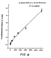
- Fig. 4 represents data from a single membrane assay prepared by saturating the antibody directly in the column. A linear relationship between signal intensity and analyte concentration is observed. The lower limit of detection for this assay is at 5 ng/ml which corresponds to part per billion (ppb) levels.
Abstract
Description
- The present invention relates generally to assays and more specifically to displacement-type assays.
- United States Patent No. 5,183,740, incorporated in its entirety herein for all purposes, describes a flow immunoassay system and method for performing displacement immunoassays. In a displacement assay, unlike a competitive assay, the antibody is exposed to labelled analyte prior to exposure to analyte. The analyte is in contact with the antibody and labelled, bound analyte an insufficient amount of time to establish equilibrium.
- Because no time needs to be dedicated to establishing equilibrium, displacement assays are faster than competitive assays. A displacement assay, however, generally provides a smaller signal than a competitive assay. In a displacement assay, the available binding sites of the antibody are saturated or nearly saturated with labelled analyte before the unlabelled analyte is added. Since equilibrium (with labelled analyte and unlabelled analyte continually binding, releasing and competing with each other for rebinding to the available binding sites on the antibody in a steady state) has not been achieved, most of the labelled analyte in a displacement assay remains bound to the antibody and unable to provide a signal.
- The relatively small signal provided by the displacement assay places an additional value on assuring the consistency of assay conditions. The bead-containing columns described in USP 5,183,740 for displacement assays must be carefully stored, prepared, and loaded to assure chemical and physical consistency (i.e., porosity, avoidance of channeling) from test to test. The need for this careful preparation and testing increases the labor, skill, and costs needed to perform accurate displacement assays. Additionally, the problems associated with the use of bead-containing columns limit the lower detection limit for displacement assays.
- In studies performed at US Drug Testing, Inc. (Rancho Cucamonga, California), better results for a displacement assay were achieved using tall, thin columns of beads coated with an antibody and labelled antigen than with short, wide columns. Furthermore, the efficiency with which the labelled antigen dissociated from antibody in the presence of unlabelled antigen was greater when flow rates were reduced and the antigen had more time to interact with the immobilized complex (Wemhoff et al. J. Immunol. Methods, 223-230, 1992). Both of these sets of experiments suggested that immobilization of the antibody and labelled antigen on a porous membrane would not provide a suitable matrix for the displacement assay since this geometry would not allow sufficient time, under flow conditions, for the antigen to interact efficiently with the complex to displace detectable amounts of the labelled antigen.
- United States Patent No. 5,369,007, to David A. Kidwell discloses a displacement assay in which samples pass through a membrane having an antibody immobilized thereon. The binding sites of the immobilized antibody are bound to an enzymatically labelled analyte. Analyte from the sample displaces the labelled analyte, causing the labelled analyte and the remainder of the sample to pass into a superabsorbent layer. The superabsorbent layer contains a substrate for the enzymatic label and any needed indicator. The Kidwell patent, however, teaches the need for a flow rate of about 0.02 ml/min and interaction times of about 1 to 5 min to assure a detectable interaction between the analyte and the antibody. In many situations, even faster results are desirable. Additionally, the Kidwell microassay card is not reusable.
- Accordingly, it is an object of this invention to perform bioassays capable of detecting minute quantities of an analyte in under one minute.
- It is another object of the present invention to quickly perform bioassays in a format that allows reuse of the matrix that selectively binds the analyte.
- These and additional objects of the invention are accomplished by quickly flowing a sample past a non-absorbent membrane having a binding element covalently bound thereto to form attachment sites for the analyte. The available attachment sites are essentially saturated with a labelled form of the analyte. Nonspecific binding sites are blocked to prevent nonspecific binding. Additionally, the sample flows past the membrane at a rate greater than that needed to achieve equilibrium between the dissociation of labelled analyte from the binding sites and the attachment of analyte (labelled or unlabelled) thereto. The processed sample is then analyzed for the presence of any labelled antigen that the unlabelled analyte has displaced from its binding site. This analysis can be qualitative or quantitative.
- A more complete appreciation of the invention will be readily obtained by reference to the following Description of the Preferred Embodiments and the accompanying drawings in which like numerals in different figures represent the same structures or elements, wherein:
- Fig. 1 schematically illustrates a device according to the present invention.
- Fig. 2 schematically illustrates an alternative embodiment of a device according to the present invention.
- Fig. 3 schematically illustrates another alternative embodiment of a device according to the present invention.
- Fig. 4 is a graph of data from a membrane assay, in accordance with the present invention, in which the membrane was prepared by the test tube incubation method.
- Fig. 5 is a graph of data from a membrane assay, in accordance with the present invention, in which the membrane was prepared by saturating the immobilized antibody with labelled analyte in the column as opposed to in a test tube.
- Fig. 6 is a graph of data from a single membrane assay, according to the present invention, prepared by saturating the antibody directly in the column.
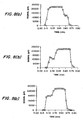
- Fig. 7 is a flowchart schematically illustrating an embodiment of an assay according to the method of the present invention.
- Figs. 8a, 8b, and 8c show the results obtained from assay performed in accordance with the method flowcharted in Fig. 7.
- Membranes useful in the present invention are typically non-absorbent (with respect to aqueous materials) materials. The non-absorbent membrane assists in providing a fast flow-through rate. Additionally, the use of a non-absorbent membrane allows the membrane, once used, to be readily rinsed of sample and reused. If displacement has occurred, reloading with labelled analyte is an option.
- Typically, membranes useful in the present invention have thicknesses, exposed surface areas, and porosities that allow detection of the analyte with an interaction time of about 0.1 sec to about 30 seconds, and typically about 1 sec to about 15 seconds, between a sample suspected of containing of the analyte and the membrane having a labelled analyte of the analyte thereon. Generally, the pore sizes in the membrane are about 0.2-1.0 microns, and are typically about 0.45 microns. Of course, other pore sizes may be used to achieve the desired interaction time. Likewise, the thickness and surface area of the membrane can be adjusted to provide the desired interaction time.
- Any non-absorbent membrane, of appropriate pore size and density of sites for immobilizing binding elements for the analyte, may be used. For example, the membrane may be a polyamide (e.g., Nylon™ membranes such as Immunodyne ABC™ (a
Nylon - Binding elements may be immobilized on the selected membrane in any manner that assures the availability on the immobilized binding element of at least one binding site for selectively binding the labelled analyte and target analyte in an aqueous medium. Several methods for attaching binding elements to the membranes are well-known and therefore will not be specifically described herein. The binding element may be immobilized either throughout the thickness of the membrane, or on only one or both surfaces thereof.
- The binding element may be any substance that can be immobilized on the membrane and that specifically binds the target analyte and its labelled analog. Binding elements include, but are not limited to, lectins, antibodies, antibiotics, and binding proteins other than antibodies and antibiotics.
- Once the binding elements have been immobilized on the membrane, their available binding sites for selectively binding with the analyte will usually be essentially saturated with a labelled analog of the analyte (denoted herein as a "labelled analyte"). Saturation of the available binding sites with the labelled analyte enhances sensitivity by assuring that the maximum number of analyte molecules will displace labelled analytes, rather than binding directly to unoccupied binding sites.
- The membrane is oriented in a manner with respect to sample flow that allows the sample to flow past the complex of binding element and labelled analyte on the membrane over the desired interaction time. The sample flows through normal to the plane of the membrane. In another alternative, the membrane support may be a hollow fiber configured so the sample flows along the hollow center before passing through the membrane. In any embodiment of the present invention, the flow of the sample through the membrane may be passive (i.e., gravitational or capillary flow) or active (flow resulting entirely or partly from the action of a flow pump, manual pressure, or vacuum).
- Any label useful in assays for the analyte may be used to label the analyte. Fluorophores are particularly useful labels. Suitable fluorophores include, but are not limited to Fluorescein, Cadaverine, Texas Red™ (Molecular Probes, Eugene, OR) and Cyanine 5™ (BDS, Pennsylvania). If used, the fluorophore label is typically one that is detectable in the visible to near infrared range.
- Once the sample has completed its interaction with the membrane having the immobilized binding element-labelled analyte thereon, the processed sample (e.g., the effluent from a sample column or the portion of the sample that has passed through and beyond the labelled portion of a test strip) is then analyzed to determine the concentration of displaced labelled analyte. The detection means for this analysis includes a readout for informing the user that a threshold amount of the label has been detected in the sample. When the label is fluorescent, the detection means also includes a light source for exciting the fluorophore-labelled analytes. The detection system can use various methods of optical measurement, including but not limited to a spectrophotometer, infrared spectrometer, fluorimeter, optical biosensor, or the eye.
- The present invention is useful in the detection, in aqueous media, of any analyte that specifically binds to the binding element. The invention may be used, for example, to detect the presence of analytes in body fluids (blood, semen, saliva, urine, etc.), water, pharmaceutical preparations, environmental samples, aerosols, foods, and beverages. If the sample suspected of containing the analyte is originally in a viscous liquid, solid, gaseous state, the sample is preferably further dissolved in water before being exposed to the membrane.
- Multiple binding elements for multiple analytes can be immobilized on a single membrane. Membranes containing the same or a different binding element can be arranged in stacks. Where multiple binding elements for multiple analytes are used, different labels on the labelled analytes can be used to distinguish which analyte is present.
- Fig. 1 schematically shows a
device 10 according to the present invention where the membrane is normal to sample flow.Membrane 12, with binding elements covalently bound or otherwise immobilized thereto and available binding sites saturated with a labelled analyte of the analyte, is positioned acrosscolumn 14. An aqueous sample entering the top ofcolumn 14 flows throughmembrane 12. Analyte in the sample interacts withmembrane 12 and displaces the labelled analyte frommembrane 12. The labelled analyte, if it does not displace another labelled analyte or unlabelled analyte from the membrane, joins the effluent fromcolumn 14. The aqueous sample effluent fromcolumn 14 then entersline 16, which carries the effluent todetector 18 for detecting the presence of the labelled analyte in the effluent fromcolumn 14. - Fig. 2 shows an alternative embodiment of the present invention, where the membrane is also normal to sample flow.
Porous membrane 102, with binding elements covalently bound or otherwise immobilized thereto and available binding sites saturated with a labelled analyte of the analyte, is positioned acrosscolumn 104 having an open tip. To prevent the flow of sample between the outer edge ofmembrane 102 and the inner wall ofcolumn 104, the membrane typically extends fully across the width ofcolumn 104. The open tip ofcolumn 104 is inserted into the top of container 106 (typically through a septum (not shown) which holds a sample suspected of containing the analyte. Suction means 105 can apply a vacuum to pull sample fromcontainer 106 throughmembrane 102 intocolumn 104. Any label in the column may be detected by a detection means external to the column. To facilitate this external detection,column 104 is preferably transparent to, or includes a suitably placed window transparent to, the energy used for detection. - Although Fig. 2 shows the suction means as a plunger and
column 104 as the syringe housing the plunger, other vacuum arrangements are possible. For example, Fig. 3 shows a design similar to that used by Vacuutainers™.Evacuated tube 204 hasporous membrane 205, with binding elements covalently bound or otherwise immobilized thereto and available binding sites saturated with a labelled analyte of the analyte, thereacross. To prevent the flow of sample between the outer edge ofporous membrane 205 and the inner wall of evacuatedtube 204, the membrane typically extends fully across the width of evacuatedtube 204. The open end of evacuatedtube 204 is sealed bycap 206 havingflange 208 extending about the rim of open end oftube 204.Tip 210 extends fromcap 206 opposite tohollow needle 212, which also extends fromcap 206.Needle 212 extends tonear septum 214 whentube 204 is placed, with only slight pressure, withinflange 208.Septum 214 maintains the vacuum in theportion 216 oftube 204. Althoughseptum 214 is essentially impermeable to gas or liquid, it is punctured byneedle 212 oncetube 204 is fully inserted intoflange 208. Upon the puncture ofseptum 214, the vacuum withinportion 216 draws liquid fromsample container 218 throughtip 210, intohollow needle 212, throughmembrane 205 and intoportion 216. Any label withinportion 216 can be detected as with other embodiments of the invention. To assure thatneedle 212 does not puncturemembrane 205, the distance between the bottom ofseptum 214 and the bottom ofmembrane 205 should be greater than the height ofneedle 212. This embodiment of the invention assures that the flow acrossmembrane 205 is consistent from sample to sample. - Having described the invention, the following examples are given to illustrate specific applications of the invention including the best mode now known to perform the invention. These specific examples are not intended to limit the scope of the invention described in this application.
- To prepare the membranes, the monoclonal 11B3 antibody (mouse lgG1) with specificity for TNT (trinitrotoluene) was immobilized onto the Immunodyne® ABC membrane with a pore size of 0.45µm. The 11B3 antibody, 100µl of a 2 nmol/ml solution in phosphate buffered saline (PBS), was attached to the membrane by either placing the solution in a test tube, with subsequent addition of the membrane, or pipetting the antibody into a column that already contained the membrane. Whether in a column or a test tube, membranes were incubated with the antibody for four hours at room temperature. Following incubation, the antibody solution was removed. Membranes exposed to antibody in a test tube were placed in a column. Any unreacted binding sites on the membrane were blocked with the addition of 100µl of 1M Tris for approximately 30 minutes. To reduce nonspecific binding, the membranes were arained and washed three times with PBS containing 0.01% Triton X-100® detergent.
- The labelled analyte was prepared by attaching the fluorophore CY5® (BDS, Pennsylvania) to trinitrobenzyl cadaverine (CY5-TNB). To saturate the antibody binding site with the labelled antigen, a solution of the CY5-TN3 (4 nmoles in 50µl PBS) was added to each column, and the columns were placed on a rocking bed overnight. The columns were connected to the fluorimeter and, washed briefly. Samples were introduced at a flow rate of 1 mL/min. Analyte injections were made in triplicate with concentrations ranging between 18.75 ng/mL and 1200 ng/mL. Fig. 2 illustrates data obtained for a membrane assay prepared with the test tube incubation method. A fluorescence signal peak was obtained at all analyte concentrations which was proportional to the amount of analyte added to the column.
- Fig. 3 represents data from a membrane assay prepared by saturating the immobilized antibody with labelled analyte in the column as opposed to in a test tube. Again, an increase in signal intensity with increasing analyte concentration was observed. However, a plateau was seen between an analyte concentration of 700 ng/mL and 1200 ng/mL where a negligible increase in signal intensity was observed despite a two-fold increase in analyte concentration suggesting that there is less labelled analyte on the membrane available for displacement, compared to the membrane prepared in the test tube.
- Both Figs. 3 and 4 demonstrate reproducible results, with minimal standard error as indicated by the error bars. Assay times were fast with the exact time being simply a function of the flow rate (1 mL/min in this case) and the length of tubing between the analyte introduction site and the fluorimeter flow cell. For these experiments, signals were generated less than 1 minute from the time of sample introduction.
- Similar experiments were conducted whereby a monoclonal antibody with specificity for the explosive, cyclonite (RDX), was immobilized onto the membrane. The procedure for immobilization was identical to the one used for the anti-TNT antibody. However, 100 µl of 0.5% casein was used instead of Tris in order to block the remaining binding sites on the membrane. Fig. 4 represents data from a single membrane assay prepared by saturating the antibody directly in the column. A linear relationship between signal intensity and analyte concentration is observed. The lower limit of detection for this assay is at 5 ng/ml which corresponds to part per billion (ppb) levels.
Claims (20)
- An assay method for detecting a target analyte, comprising the steps of:providing a porous membrane having binding elements immobilized thereon, each of said binding elements having at least one binding site capable of specifically binding to said target analyte;exposing said binding sites to a labelled analog of the target analyte to form complexes of membrane-immobilized binding elements and labelled analogs;flowing an aqueous sample, suspected of containing the target analyte, normal to and through said membrane having said complexes thereon, at a flow rate allowing the target analyte to displace the labelled analyte from the complexes under non-equilibrium conditions, said flow rate also providing an interaction time between said analyte and said membrane of about 0.1 sec through about 30 sec;detecting the displaced labelled analyte, the amount of said displaced labelled analyte being proportional to the concentration of said target analyte in said sample.
- The method of claim 1, wherein the binding element is an antibody.
- The method of claim 1, wherein said labelled analog is fluorescently labelled.
- The method of claim 1, wherein said interaction time is no more than about 15 seconds.
- The method of claim 1, wherein said membrane is nonabsorbent.
- The method of claim 5, wherein said membrane is selected from the group consisting of cellulose, nitrocellulose, silica fiber, aluminum oxide, and polyvinyl chloride.
- The method of claim 5, further comprising, after said detecting step, the steps of: rinsing said sample from said membrane;
flowing a second aqueous liquid sample, suspected of containing target analyte, so as to flow said second liquid sample normal to and through said rinsed membrane having said complexes thereon, at a flow rate allowing said target analyte in said second sample to displace the labelled analog from the complexes under non-equilibrium conditions to form downstream of said membrane a flowable liquid effluent including said labelled analog displaced by said target analyte in said second sample, said flow rate also providing an interaction time between said target analyte in said second sample and said membrane of about 0.1 sec through about 30 sec;
detecting the displaced labelled analyte, the amount of said displaced labelled analyte being proportional to the concentration of said target analyte in said sample. - A device for the assay of an aqueous sample suspected of containing a target analyte, comprising:a porous membrane having binding elements immobilized thereon, each of said binding elements having at least one binding site capable of specifically binding to said target analyte, essentially all of said binding sites on said membrane being occupied by a labelled analog of the target analyte to form complexes of membrane-immobilized binding elements and labelled analogs;flow means for flowing an aqueous sample, suspected of containing the target analyte, normal to and through said membrane having said complexes thereon, at a flow rate allowing the target analyte to displace the labelled analog from the complexes under non-equilibrium conditions to form a processed sample, said flow rate also providing an interaction time between said analyte and said membrane of about 0.1 sec through about 30 sec; and detecting means for detecting the presence of said labelled analog in said processed sample.
- The device of claim 8, wherein said labelled analog is fluorescently labelled.
- The device of claim 9, wherein said detecting means further includes a light source for exciting any fluorescently labelled analog in said processed sample.
- The device of claim 8, wherein said binding element is an antibody.
- The device of claim 10, wherein said detecting means further is adapted to quantitatively determine the amount of said labelled analog in said processed sample.
- The device of claim 10, wherein said detecting means further comprises a spectrophotometer, infrared spectrometer, fluorimeter or an optical biosensor.
- The device of claim 8, wherein said flow means comprises a conduit through which said sample flows by the action of gravity or by manual force.
- The device of claim 8, wherein said membrane is nonabsorbent.
- The device of claim 15, wherein, after said device has been used to assay a first aqueous sample suspected of containing said liquid analyte by a method according to claim 1, said membrane may be rinsed and said device may be reused.
- The device of claim 8, wherein said flow means is adapted to provide an interaction time between said analyte and said membrane of no more than about 15 sec.
- A device for the assay of an aqueous sample suspected of containing a target analyte, comprising:a container, said container including an open end for receiving a liquid sample suspected of containing an analyte, a closed end, a porous membrane extending fully across the width of said container, and a reservoir between said membrane and said closed end, said membrane having binding elements immobilized thereon, each of said binding elements having at least one binding site capable of specifically binding to said target analyte, essentially all of said binding sites on said membrane being occupied by a labelled analog of the target analyte to form complexes of membrane-immobilized binding elements and labelled analytes;flow means for flowing a liquid sample through said open end, through said membrane, and into said reservoir at a flow rate allowing the target analyte to displace the labelled analyte from the complexes under non-equilibrium conditions, said flow rate providing an interaction time between said analyte and said membrane of about 0.1 sec through about 30 sec;detecting means for detecting the presence of said labelled analog in said reservoir.
- A device for the immunoassay of an aqueous sample suspected of containing a target analyte, comprising:a container, said container including an open end and a closed end;a cap within which said open end of said container may be fitted in a first position in which the closed end of said container is a first distance from said cap and in a second position in which the closed end of said container is a second distance from said cap, said second distance being less than said first distance;a tip for receiving said aqueous sample extending outwardly from said cap;a hollow needle extending from said cap in a direction opposite to said tip;a septum extending across the width of said container, said septum being positioned between said closed end of said container and an end of said needle distal to said cap when said container is seated in said first position, said septum being essentially impermeable to fluid;a porous membrane positioned between said septum and said closed end of said container, said membrane extending across the width of said container, and a reservoir between said membrane and said closed end, said membrane having binding elements immobilized thereon, each of said binding elements having at least one binding site capable of specifically binding to said target analyte, essentially all of said binding sites on said membrane being either occupied by a labelled analog of the target analyte to form complexes of membrane-immobilized binding elements and labelled analytes;an evacuated reservoir between said membrane and said closed end of said container;a detecting means for detecting the presence of said labelled analog in said reservoir;said hollow needle being positioned so as to puncture said septum, but not said membrane, when said container is in said second position.
- The device of claim 19, further comprising a sample holding means having liquid sample therein, wherein said puncture of said membrane causes liquid sample from said sample holding means to flow through said open end, through said membrane, and into said reservoir.
Applications Claiming Priority (3)
| Application Number | Priority Date | Filing Date | Title |
|---|---|---|---|
| US583912 | 1996-01-11 | ||
| US08/583,912 US6750031B1 (en) | 1996-01-11 | 1996-01-11 | Displacement assay on a porous membrane |
| PCT/US1996/016981 WO1997025619A1 (en) | 1996-01-11 | 1996-10-18 | Displacement assay on a porous membrane |
Publications (3)
| Publication Number | Publication Date |
|---|---|
| EP0880699A1 EP0880699A1 (en) | 1998-12-02 |
| EP0880699A4 EP0880699A4 (en) | 2002-04-10 |
| EP0880699B1 true EP0880699B1 (en) | 2006-05-24 |
Family
ID=24335115
Family Applications (1)
| Application Number | Title | Priority Date | Filing Date |
|---|---|---|---|
| EP96938636A Expired - Lifetime EP0880699B1 (en) | 1996-01-11 | 1996-10-18 | Displacement assay on a porous membrane |
Country Status (5)
| Country | Link |
|---|---|
| US (2) | US6750031B1 (en) |
| EP (1) | EP0880699B1 (en) |
| AT (1) | ATE327507T1 (en) |
| DE (1) | DE69636173T2 (en) |
| WO (1) | WO1997025619A1 (en) |
Families Citing this family (104)
| Publication number | Priority date | Publication date | Assignee | Title |
|---|---|---|---|---|
| US5891740A (en) * | 1997-04-02 | 1999-04-06 | The Perkin-Elmer Corporation | Detection of low level hydrophobic analytes in environmental samples using agglutination reaction capillary slide test and apparatus therefor |
| US6036924A (en) | 1997-12-04 | 2000-03-14 | Hewlett-Packard Company | Cassette of lancet cartridges for sampling blood |
| GB9726888D0 (en) * | 1997-12-20 | 1998-02-18 | Eev Ltd | Detection |
| US6391005B1 (en) | 1998-03-30 | 2002-05-21 | Agilent Technologies, Inc. | Apparatus and method for penetration with shaft having a sensor for sensing penetration depth |
| US7192778B2 (en) * | 1999-10-06 | 2007-03-20 | Natan Michael J | Surface enhanced spectroscopy-active composite nanoparticles |
| US8497131B2 (en) * | 1999-10-06 | 2013-07-30 | Becton, Dickinson And Company | Surface enhanced spectroscopy-active composite nanoparticles comprising Raman-active reporter molecules |
| US8641644B2 (en) | 2000-11-21 | 2014-02-04 | Sanofi-Aventis Deutschland Gmbh | Blood testing apparatus having a rotatable cartridge with multiple lancing elements and testing means |
| US6861263B2 (en) | 2001-01-26 | 2005-03-01 | Surromed, Inc. | Surface-enhanced spectroscopy-active sandwich nanoparticles |
| US7749174B2 (en) | 2001-06-12 | 2010-07-06 | Pelikan Technologies, Inc. | Method and apparatus for lancet launching device intergrated onto a blood-sampling cartridge |
| US8337419B2 (en) | 2002-04-19 | 2012-12-25 | Sanofi-Aventis Deutschland Gmbh | Tissue penetration device |
| EP1404232B1 (en) | 2001-06-12 | 2009-12-02 | Pelikan Technologies Inc. | Blood sampling apparatus and method |
| US9226699B2 (en) | 2002-04-19 | 2016-01-05 | Sanofi-Aventis Deutschland Gmbh | Body fluid sampling module with a continuous compression tissue interface surface |
| US7981056B2 (en) | 2002-04-19 | 2011-07-19 | Pelikan Technologies, Inc. | Methods and apparatus for lancet actuation |
| US7316700B2 (en) | 2001-06-12 | 2008-01-08 | Pelikan Technologies, Inc. | Self optimizing lancing device with adaptation means to temporal variations in cutaneous properties |
| DE60238119D1 (en) | 2001-06-12 | 2010-12-09 | Pelikan Technologies Inc | ELECTRIC ACTUATOR ELEMENT FOR A LANZETTE |
| US9795747B2 (en) | 2010-06-02 | 2017-10-24 | Sanofi-Aventis Deutschland Gmbh | Methods and apparatus for lancet actuation |
| US9427532B2 (en) | 2001-06-12 | 2016-08-30 | Sanofi-Aventis Deutschland Gmbh | Tissue penetration device |
| US7025774B2 (en) | 2001-06-12 | 2006-04-11 | Pelikan Technologies, Inc. | Tissue penetration device |
| US7699791B2 (en) | 2001-06-12 | 2010-04-20 | Pelikan Technologies, Inc. | Method and apparatus for improving success rate of blood yield from a fingerstick |
| SE0102922D0 (en) * | 2001-08-31 | 2001-08-31 | Astrazeneca Ab | Method and apparatus for sample preparation |
| WO2017193213A1 (en) | 2016-05-10 | 2017-11-16 | Jp Scientific Limited | System and method for desorbing and detecting an analyte sorbed on a solid phase microextraction device |
| JP4381820B2 (en) * | 2002-03-11 | 2009-12-09 | ポーリスツィン、ジャヌス・ビー | Micro extractor for biological tissue examination |
| US9870907B2 (en) | 2002-03-11 | 2018-01-16 | Jp Scientific Limited | Probe for extraction of molecules of interest from a sample |
| US8598325B2 (en) | 2002-03-11 | 2013-12-03 | Janusz B. Pawliszyn | Solid-phase microextraction coatings and methods for their preparation |
| US7232689B2 (en) * | 2002-03-11 | 2007-06-19 | Pawliszyn Janusz B | Calibration procedure for investigating biological systems |
| US20090026122A1 (en) | 2002-03-11 | 2009-01-29 | Janusz | Biocompatible solid-phase microextraction coatings and methods for their preparation |
| US9733234B2 (en) | 2002-03-11 | 2017-08-15 | Jp Scientific Limited | Probe for extraction of molecules of interest from a sample |
| GB2387130A (en) * | 2002-04-04 | 2003-10-08 | Fluid Technologies Plc | Hollow fibre filter membrane unit with microorganism detector, and associated usage |
| US7901362B2 (en) | 2002-04-19 | 2011-03-08 | Pelikan Technologies, Inc. | Method and apparatus for penetrating tissue |
| US9248267B2 (en) | 2002-04-19 | 2016-02-02 | Sanofi-Aventis Deustchland Gmbh | Tissue penetration device |
| US7229458B2 (en) | 2002-04-19 | 2007-06-12 | Pelikan Technologies, Inc. | Method and apparatus for penetrating tissue |
| US8372016B2 (en) | 2002-04-19 | 2013-02-12 | Sanofi-Aventis Deutschland Gmbh | Method and apparatus for body fluid sampling and analyte sensing |
| US7674232B2 (en) | 2002-04-19 | 2010-03-09 | Pelikan Technologies, Inc. | Method and apparatus for penetrating tissue |
| US8579831B2 (en) | 2002-04-19 | 2013-11-12 | Sanofi-Aventis Deutschland Gmbh | Method and apparatus for penetrating tissue |
| US8784335B2 (en) | 2002-04-19 | 2014-07-22 | Sanofi-Aventis Deutschland Gmbh | Body fluid sampling device with a capacitive sensor |
| US7547287B2 (en) | 2002-04-19 | 2009-06-16 | Pelikan Technologies, Inc. | Method and apparatus for penetrating tissue |
| US7371247B2 (en) | 2002-04-19 | 2008-05-13 | Pelikan Technologies, Inc | Method and apparatus for penetrating tissue |
| US7976476B2 (en) | 2002-04-19 | 2011-07-12 | Pelikan Technologies, Inc. | Device and method for variable speed lancet |
| US7291117B2 (en) | 2002-04-19 | 2007-11-06 | Pelikan Technologies, Inc. | Method and apparatus for penetrating tissue |
| US8267870B2 (en) | 2002-04-19 | 2012-09-18 | Sanofi-Aventis Deutschland Gmbh | Method and apparatus for body fluid sampling with hybrid actuation |
| US8702624B2 (en) | 2006-09-29 | 2014-04-22 | Sanofi-Aventis Deutschland Gmbh | Analyte measurement device with a single shot actuator |
| US8360992B2 (en) | 2002-04-19 | 2013-01-29 | Sanofi-Aventis Deutschland Gmbh | Method and apparatus for penetrating tissue |
| US7175642B2 (en) | 2002-04-19 | 2007-02-13 | Pelikan Technologies, Inc. | Methods and apparatus for lancet actuation |
| US9795334B2 (en) | 2002-04-19 | 2017-10-24 | Sanofi-Aventis Deutschland Gmbh | Method and apparatus for penetrating tissue |
| US7297122B2 (en) | 2002-04-19 | 2007-11-20 | Pelikan Technologies, Inc. | Method and apparatus for penetrating tissue |
| US7648468B2 (en) | 2002-04-19 | 2010-01-19 | Pelikon Technologies, Inc. | Method and apparatus for penetrating tissue |
| US7717863B2 (en) | 2002-04-19 | 2010-05-18 | Pelikan Technologies, Inc. | Method and apparatus for penetrating tissue |
| US9314194B2 (en) | 2002-04-19 | 2016-04-19 | Sanofi-Aventis Deutschland Gmbh | Tissue penetration device |
| US7331931B2 (en) | 2002-04-19 | 2008-02-19 | Pelikan Technologies, Inc. | Method and apparatus for penetrating tissue |
| US7713214B2 (en) | 2002-04-19 | 2010-05-11 | Pelikan Technologies, Inc. | Method and apparatus for a multi-use body fluid sampling device with optical analyte sensing |
| US8221334B2 (en) | 2002-04-19 | 2012-07-17 | Sanofi-Aventis Deutschland Gmbh | Method and apparatus for penetrating tissue |
| US7892183B2 (en) | 2002-04-19 | 2011-02-22 | Pelikan Technologies, Inc. | Method and apparatus for body fluid sampling and analyte sensing |
| US7232451B2 (en) | 2002-04-19 | 2007-06-19 | Pelikan Technologies, Inc. | Method and apparatus for penetrating tissue |
| US7909778B2 (en) | 2002-04-19 | 2011-03-22 | Pelikan Technologies, Inc. | Method and apparatus for penetrating tissue |
| US7491178B2 (en) | 2002-04-19 | 2009-02-17 | Pelikan Technologies, Inc. | Method and apparatus for penetrating tissue |
| AU2003273530A1 (en) * | 2002-06-03 | 2003-12-19 | Pamgene B.V. | Biomolecular kinetics method using a flow-through microarray |
| US20040101900A1 (en) * | 2002-11-25 | 2004-05-27 | Mauro J. Mattew | Assay for rapid detection of TNT |
| US8574895B2 (en) | 2002-12-30 | 2013-11-05 | Sanofi-Aventis Deutschland Gmbh | Method and apparatus using optical techniques to measure analyte levels |
| US20040147619A1 (en) * | 2003-01-23 | 2004-07-29 | Conocophillips Company | Chlorine-containing synthesis gas catalyst |
| US8262614B2 (en) | 2003-05-30 | 2012-09-11 | Pelikan Technologies, Inc. | Method and apparatus for fluid injection |
| US7850621B2 (en) | 2003-06-06 | 2010-12-14 | Pelikan Technologies, Inc. | Method and apparatus for body fluid sampling and analyte sensing |
| WO2006001797A1 (en) | 2004-06-14 | 2006-01-05 | Pelikan Technologies, Inc. | Low pain penetrating |
| WO2005033659A2 (en) | 2003-09-29 | 2005-04-14 | Pelikan Technologies, Inc. | Method and apparatus for an improved sample capture device |
| EP1680014A4 (en) | 2003-10-14 | 2009-01-21 | Pelikan Technologies Inc | Method and apparatus for a variable user interface |
| US7943395B2 (en) * | 2003-11-21 | 2011-05-17 | Kimberly-Clark Worldwide, Inc. | Extension of the dynamic detection range of assay devices |
| US7822454B1 (en) | 2005-01-03 | 2010-10-26 | Pelikan Technologies, Inc. | Fluid sampling device with improved analyte detecting member configuration |
| US8668656B2 (en) | 2003-12-31 | 2014-03-11 | Sanofi-Aventis Deutschland Gmbh | Method and apparatus for improving fluidic flow and sample capture |
| CA2552233A1 (en) * | 2004-02-11 | 2005-08-25 | Pamgene B.V. | A device for analysing an interaction between target and probe molecules |
| US7781226B2 (en) * | 2004-02-27 | 2010-08-24 | The Board Of Regents Of The University Of Texas System | Particle on membrane assay system |
| US8105849B2 (en) | 2004-02-27 | 2012-01-31 | Board Of Regents, The University Of Texas System | Integration of fluids and reagents into self-contained cartridges containing sensor elements |
| WO2005083423A2 (en) | 2004-02-27 | 2005-09-09 | Board Of Regents, The University Of Texas System | System and method for integrating fluids and reagents in self-contained cartridges containing particle and membrane sensor elements |
| US20060257941A1 (en) * | 2004-02-27 | 2006-11-16 | Mcdevitt John T | Integration of fluids and reagents into self-contained cartridges containing particle and membrane sensor elements |
| US20060257991A1 (en) * | 2004-02-27 | 2006-11-16 | Mcdevitt John T | Integration of fluids and reagents into self-contained cartridges containing particle-based sensor elements and membrane-based sensor elements |
| US8101431B2 (en) | 2004-02-27 | 2012-01-24 | Board Of Regents, The University Of Texas System | Integration of fluids and reagents into self-contained cartridges containing sensor elements and reagent delivery systems |
| WO2006011062A2 (en) | 2004-05-20 | 2006-02-02 | Albatros Technologies Gmbh & Co. Kg | Printable hydrogel for biosensors |
| EP1765194A4 (en) | 2004-06-03 | 2010-09-29 | Pelikan Technologies Inc | Method and apparatus for a fluid sampling device |
| US9775553B2 (en) | 2004-06-03 | 2017-10-03 | Sanofi-Aventis Deutschland Gmbh | Method and apparatus for a fluid sampling device |
| US8652831B2 (en) | 2004-12-30 | 2014-02-18 | Sanofi-Aventis Deutschland Gmbh | Method and apparatus for analyte measurement test time |
| WO2006098804A2 (en) | 2005-03-11 | 2006-09-21 | Chembio Diagnostic Systems, Inc. | Dual path immunoassay device |
| US7189522B2 (en) | 2005-03-11 | 2007-03-13 | Chembio Diagnostic Systems, Inc. | Dual path immunoassay device |
| AU2006309284B2 (en) | 2005-05-31 | 2012-08-02 | Board Of Regents, The University Of Texas System | Methods and compositions related to determination and use of white blood cell counts |
| US20090298197A1 (en) * | 2005-11-15 | 2009-12-03 | Oxonica Materials Inc. | Sers-based methods for detection of bioagents |
| US8409411B2 (en) | 2005-12-02 | 2013-04-02 | State Of Oregon Acting By And Through The State Board Of Higher Education On Behalf Of Portland State University | Nano-porous membrane based sensors |
| US8409863B2 (en) | 2005-12-14 | 2013-04-02 | Becton, Dickinson And Company | Nanoparticulate chemical sensors using SERS |
| US7723100B2 (en) | 2006-01-13 | 2010-05-25 | Becton, Dickinson And Company | Polymer coated SERS nanotag |
| EP1977242B1 (en) * | 2006-01-27 | 2016-08-03 | Becton Dickinson and Company | Lateral flow immunoassay with encapsulated detection modality |
| JP5277165B2 (en) * | 2006-07-24 | 2013-08-28 | ベクトン・ディキンソン・アンド・カンパニー | Analytical particle agglomeration and imaging apparatus and method |
| US7879622B1 (en) * | 2006-08-11 | 2011-02-01 | University Of South Florida | Barrier-permeable proxy reporter analysis |
| WO2008105814A2 (en) * | 2006-08-22 | 2008-09-04 | Los Alamos National Security, Llc | Miniturized lateral flow device for rapid and sensitive detection of proteins or nucleic acids |
| US8101403B2 (en) | 2006-10-04 | 2012-01-24 | University Of Washington | Method and device for rapid parallel microfluidic molecular affinity assays |
| US8613214B2 (en) * | 2008-01-09 | 2013-12-24 | Orono Spectral Solutions, Inc. | Apparatus and method for determining analyte content in a fluid |
| EP2265324B1 (en) | 2008-04-11 | 2015-01-28 | Sanofi-Aventis Deutschland GmbH | Integrated analyte measurement system |
| EP3067694A1 (en) | 2008-05-05 | 2016-09-14 | Los Alamos National Security, LLC | Lateral flow-based nucleic acid sample preparation device, integrated with passive fluid flow control |
| US20100022916A1 (en) | 2008-07-24 | 2010-01-28 | Javanbakhsh Esfandiari | Method and Apparatus for Collecting and Preparing Biological Samples for Testing |
| WO2010027812A2 (en) * | 2008-08-25 | 2010-03-11 | University Of Washington | Microfluidic systems incorporating flow-through membranes |
| US9375169B2 (en) | 2009-01-30 | 2016-06-28 | Sanofi-Aventis Deutschland Gmbh | Cam drive for managing disposable penetrating member actions with a single motor and motor and control system |
| US8965476B2 (en) | 2010-04-16 | 2015-02-24 | Sanofi-Aventis Deutschland Gmbh | Tissue penetration device |
| GB201017447D0 (en) | 2010-10-15 | 2010-12-01 | Moorlodge Biotech Ventures Ltd | Assay device |
| US8603835B2 (en) | 2011-02-10 | 2013-12-10 | Chembio Diagnostic Systems, Inc. | Reduced step dual path immunoassay device and method |
| DK2699700T3 (en) | 2011-04-20 | 2016-08-01 | Mesa Biotech Inc | Integrated device for nukleinsyreregistrering and identification |
| EP3126486B1 (en) | 2014-04-02 | 2019-07-03 | Chembio Diagnostic Systems, Inc. | Immunoassay utilizing trapping conjugate |
| US20160116466A1 (en) | 2014-10-27 | 2016-04-28 | Chembio Diagnostic Systems, Inc. | Rapid Screening Assay for Qualitative Detection of Multiple Febrile Illnesses |
| GB201510850D0 (en) | 2015-06-19 | 2015-08-05 | Cambridge Molecular Diagnositcs Ltd | Nucleic acid amplification and detection assays |
| US10545077B2 (en) | 2016-03-02 | 2020-01-28 | Jp Scientific Limited | Solid phase microextraction coating |
Family Cites Families (18)
| Publication number | Priority date | Publication date | Assignee | Title |
|---|---|---|---|---|
| US3800780A (en) * | 1972-02-23 | 1974-04-02 | Angelika Elliott | Vacuum indicator |
| US4258001A (en) | 1978-12-27 | 1981-03-24 | Eastman Kodak Company | Element, structure and method for the analysis or transport of liquids |
| US4895809A (en) * | 1984-01-09 | 1990-01-23 | Varian Associates, Inc. | Immobilized antigen-antibody displacement process |
| US4859583A (en) | 1985-02-25 | 1989-08-22 | Amoco Corporation | Chemiluminescent immunochemical technique for low molecular weight antigens |
| US4916056A (en) | 1986-02-18 | 1990-04-10 | Abbott Laboratories | Solid-phase analytical device and method for using same |
| US4812293A (en) * | 1986-06-30 | 1989-03-14 | Becton, Dickinson And Company | Vacuum actuated assay device and method of using same |
| US4920046A (en) | 1987-02-20 | 1990-04-24 | Becton, Dickinson And Company | Process, test device, and test kit for a rapid assay having a visible readout |
| US5206177A (en) * | 1988-01-21 | 1993-04-27 | Boehringer Mannheim Corporation | Apparatus for determining an analyte and method therefor |
| US5045479A (en) * | 1988-07-05 | 1991-09-03 | The Johns Hopkins University | Continuous flow competitive assay with reference system |
| US5024238A (en) * | 1989-01-10 | 1991-06-18 | Cancer Diagnostics, Inc. | Blood withdrawing apparatus and antigen testing method |
| US5766933A (en) * | 1989-04-26 | 1998-06-16 | Diagnostic Products Corporation | Method and element for measuring analytes in biological fluids using immobilized binder--analyte labeled complex |
| US5183740A (en) | 1990-02-23 | 1993-02-02 | The United States Of America As Represented By The Secretary Of The Navy | Flow immunosensor method and apparatus |
| EP0467078B1 (en) * | 1990-07-18 | 1996-05-08 | Abbott Laboratories | An analyte-subtitute reagent for use in specific binding assay methods, devices and kits |
| US5200321A (en) | 1990-09-07 | 1993-04-06 | The United States Of America As Represented By The Secretary Of The Navy | Microassay on a card |
| DE4229591C1 (en) * | 1992-09-04 | 1994-03-24 | Draegerwerk Ag | Immunoassay using test strip with immobilised antibody - based on displacement of tracer from antibody by analyte, esp. for determn. of pollutants |
| US5354654A (en) * | 1993-07-16 | 1994-10-11 | The United States Of America As Represented By The Secretary Of The Navy | Lyophilized ligand-receptor complexes for assays and sensors |
| US5602037A (en) * | 1994-06-30 | 1997-02-11 | Dade International, Inc. | Combination reagent holding and test device |
| US6016712A (en) * | 1997-09-18 | 2000-01-25 | Accumetrics | Device for receiving and processing a sample |
-
1996
- 1996-01-11 US US08/583,912 patent/US6750031B1/en not_active Expired - Fee Related
- 1996-10-18 EP EP96938636A patent/EP0880699B1/en not_active Expired - Lifetime
- 1996-10-18 WO PCT/US1996/016981 patent/WO1997025619A1/en active IP Right Grant
- 1996-10-18 AT AT96938636T patent/ATE327507T1/en not_active IP Right Cessation
- 1996-10-18 DE DE69636173T patent/DE69636173T2/en not_active Expired - Lifetime
-
2001
- 2001-07-13 US US09/907,888 patent/US6808937B2/en not_active Expired - Fee Related
Also Published As
| Publication number | Publication date |
|---|---|
| WO1997025619A1 (en) | 1997-07-17 |
| DE69636173D1 (en) | 2006-06-29 |
| EP0880699A4 (en) | 2002-04-10 |
| US20020028475A1 (en) | 2002-03-07 |
| EP0880699A1 (en) | 1998-12-02 |
| US6750031B1 (en) | 2004-06-15 |
| ATE327507T1 (en) | 2006-06-15 |
| DE69636173T2 (en) | 2007-03-29 |
| US6808937B2 (en) | 2004-10-26 |
Similar Documents
| Publication | Publication Date | Title |
|---|---|---|
| EP0880699B1 (en) | Displacement assay on a porous membrane | |
| JP4040110B2 (en) | Analytical instrument for membrane-based assays | |
| US7910381B2 (en) | Immuno gold lateral flow assay | |
| EP0046004B1 (en) | Concentrating zone method in heterogeneous immunoassays | |
| FI96639C (en) | Self-sufficient immunoassay element | |
| KR100513216B1 (en) | Biosensor | |
| US5183740A (en) | Flow immunosensor method and apparatus | |
| US7569397B2 (en) | Immunoassay devices and use thereof | |
| EP1789793B1 (en) | Combination assay for alcohol and drugs of abuse | |
| US20110097734A1 (en) | Flow Control Technique for Assay Devices | |
| EP0274911B1 (en) | Diagnostic device, method for making, and method for using | |
| US20150017656A1 (en) | Rapid Lateral Flow Assay Method for Detecting Low Quantity Liquid or Dry Samples | |
| CA1289471C (en) | Dry test strip for devices using oxygen demanding detection system | |
| US8142735B2 (en) | Test apparatus | |
| CA1302244C (en) | Dry test strips having a red blood cell exclusion layer preventing interference by red blood cells in analyte detection visualization | |
| EP0402023A1 (en) | Elongated membrane flow-through diagnostic device and method | |
| WO2014168580A1 (en) | Double-chamber bi-directional reverse flow device | |
| CA2241324C (en) | Displacement assay on a porous membrane | |
| Ligler et al. | Displacement Assay on a Porous Membrane. | |
| JP3007410B2 (en) | Multiwell test | |
| JP2002116206A (en) | Immunoassay apparatus | |
| MXPA98005608A (en) | Proof of displacement on a membrane by | |
| JPS63139248A (en) | Enzyme immunoassay sensor and detection of antigen or antibody | |
| KR20180082274A (en) | Signal amplification kit and manufacturing method thereof in Lateral flow immunoassay | |
| US20140134049A1 (en) | Lateral Flow Assay Device for Measuring Low Quantity Sample |
Legal Events
| Date | Code | Title | Description |
|---|---|---|---|
| PUAI | Public reference made under article 153(3) epc to a published international application that has entered the european phase |
Free format text: ORIGINAL CODE: 0009012 |
|
| 17P | Request for examination filed |
Effective date: 19980619 |
|
| AK | Designated contracting states |
Kind code of ref document: A1 Designated state(s): AT BE DE ES FR GB IT NL |
|
| A4 | Supplementary search report drawn up and despatched |
Effective date: 20020226 |
|
| AK | Designated contracting states |
Kind code of ref document: A4 Designated state(s): AT BE DE ES FR GB IT NL |
|
| 17Q | First examination report despatched |
Effective date: 20040310 |
|
| GRAP | Despatch of communication of intention to grant a patent |
Free format text: ORIGINAL CODE: EPIDOSNIGR1 |
|
| GRAS | Grant fee paid |
Free format text: ORIGINAL CODE: EPIDOSNIGR3 |
|
| GRAA | (expected) grant |
Free format text: ORIGINAL CODE: 0009210 |
|
| AK | Designated contracting states |
Kind code of ref document: B1 Designated state(s): AT BE DE ES FR GB IT NL |
|
| PG25 | Lapsed in a contracting state [announced via postgrant information from national office to epo] |
Ref country code: NL Free format text: LAPSE BECAUSE OF FAILURE TO SUBMIT A TRANSLATION OF THE DESCRIPTION OR TO PAY THE FEE WITHIN THE PRESCRIBED TIME-LIMIT Effective date: 20060524 Ref country code: IT Free format text: LAPSE BECAUSE OF FAILURE TO SUBMIT A TRANSLATION OF THE DESCRIPTION OR TO PAY THE FEE WITHIN THE PRESCRIBED TIME-LIMIT;WARNING: LAPSES OF ITALIAN PATENTS WITH EFFECTIVE DATE BEFORE 2007 MAY HAVE OCCURRED AT ANY TIME BEFORE 2007. THE CORRECT EFFECTIVE DATE MAY BE DIFFERENT FROM THE ONE RECORDED. Effective date: 20060524 Ref country code: BE Free format text: LAPSE BECAUSE OF FAILURE TO SUBMIT A TRANSLATION OF THE DESCRIPTION OR TO PAY THE FEE WITHIN THE PRESCRIBED TIME-LIMIT Effective date: 20060524 Ref country code: AT Free format text: LAPSE BECAUSE OF FAILURE TO SUBMIT A TRANSLATION OF THE DESCRIPTION OR TO PAY THE FEE WITHIN THE PRESCRIBED TIME-LIMIT Effective date: 20060524 |
|
| REG | Reference to a national code |
Ref country code: GB Ref legal event code: FG4D |
|
| REF | Corresponds to: |
Ref document number: 69636173 Country of ref document: DE Date of ref document: 20060629 Kind code of ref document: P |
|
| PG25 | Lapsed in a contracting state [announced via postgrant information from national office to epo] |
Ref country code: ES Free format text: LAPSE BECAUSE OF FAILURE TO SUBMIT A TRANSLATION OF THE DESCRIPTION OR TO PAY THE FEE WITHIN THE PRESCRIBED TIME-LIMIT Effective date: 20060904 |
|
| NLV1 | Nl: lapsed or annulled due to failure to fulfill the requirements of art. 29p and 29m of the patents act | ||
| ET | Fr: translation filed | ||
| PLBE | No opposition filed within time limit |
Free format text: ORIGINAL CODE: 0009261 |
|
| STAA | Information on the status of an ep patent application or granted ep patent |
Free format text: STATUS: NO OPPOSITION FILED WITHIN TIME LIMIT |
|
| 26N | No opposition filed |
Effective date: 20070227 |
|
| PGFP | Annual fee paid to national office [announced via postgrant information from national office to epo] |
Ref country code: FR Payment date: 20101209 Year of fee payment: 15 |
|
| PGFP | Annual fee paid to national office [announced via postgrant information from national office to epo] |
Ref country code: DE Payment date: 20101129 Year of fee payment: 15 |
|
| PGFP | Annual fee paid to national office [announced via postgrant information from national office to epo] |
Ref country code: GB Payment date: 20101104 Year of fee payment: 15 |
|
| GBPC | Gb: european patent ceased through non-payment of renewal fee |
Effective date: 20111018 |
|
| REG | Reference to a national code |
Ref country code: FR Ref legal event code: ST Effective date: 20120629 |
|
| PG25 | Lapsed in a contracting state [announced via postgrant information from national office to epo] |
Ref country code: DE Free format text: LAPSE BECAUSE OF NON-PAYMENT OF DUE FEES Effective date: 20120501 |
|
| REG | Reference to a national code |
Ref country code: DE Ref legal event code: R119 Ref document number: 69636173 Country of ref document: DE Effective date: 20120501 |
|
| PG25 | Lapsed in a contracting state [announced via postgrant information from national office to epo] |
Ref country code: GB Free format text: LAPSE BECAUSE OF NON-PAYMENT OF DUE FEES Effective date: 20111018 Ref country code: FR Free format text: LAPSE BECAUSE OF NON-PAYMENT OF DUE FEES Effective date: 20111102 |