EP0882639A2 - Karosserierahmenbauteil für die Karosserie eines Kraftfahrzeuges und Verfahren für dessen Herstellung - Google Patents
Karosserierahmenbauteil für die Karosserie eines Kraftfahrzeuges und Verfahren für dessen Herstellung Download PDFInfo
- Publication number
- EP0882639A2 EP0882639A2 EP98107615A EP98107615A EP0882639A2 EP 0882639 A2 EP0882639 A2 EP 0882639A2 EP 98107615 A EP98107615 A EP 98107615A EP 98107615 A EP98107615 A EP 98107615A EP 0882639 A2 EP0882639 A2 EP 0882639A2
- Authority
- EP
- European Patent Office
- Prior art keywords
- body frame
- frame component
- holes
- hole
- component according
- Prior art date
- Legal status (The legal status is an assumption and is not a legal conclusion. Google has not performed a legal analysis and makes no representation as to the accuracy of the status listed.)
- Granted
Links
Images

Classifications
-
- B—PERFORMING OPERATIONS; TRANSPORTING
- B62—LAND VEHICLES FOR TRAVELLING OTHERWISE THAN ON RAILS
- B62D—MOTOR VEHICLES; TRAILERS
- B62D21/00—Understructures, i.e. chassis frame on which a vehicle body may be mounted
- B62D21/15—Understructures, i.e. chassis frame on which a vehicle body may be mounted having impact absorbing means, e.g. a frame designed to permanently or temporarily change shape or dimension upon impact with another body
Definitions
- the invention relates to a body frame component for the body of a motor vehicle, wherein the body frame member has a specific shape and for receiving at least one force acting on the body frame component is formed, wherein due to the specific shape of the body frame component when absorbing this force different within different areas of the body frame component Load or stress conditions exist, especially in a first area high and, in a second area, lower load or stress conditions occur.
- the invention further relates to a method for producing a Body frame component for the body of a motor vehicle, the Body frame component made of a substantially flat material by reshaping a specific form that can be built into a body is formed and that Body frame component - when installed in the body - at least one the body frame component absorbs the force acting, when absorbing this force due to the specific shape of the body frame component within different Areas of the body frame component different load or Stress states are generated.
- body frame components known that can be manufactured in different ways, so that Total weight of the motor vehicle is as low as possible. So that these Body frame components that can absorb the forces acting on them have the Body frame components on the one hand a specific shape and their purpose a corresponding material thickness.
- the material thickness is in different areas of the body frame component depending on the load or Tension states are designed differently. So in areas with high stress or Stress states also provide a much greater "material thickness" than in Areas with lower stress or stress conditions.
- structural elements to be arranged separately are known in the prior art (DE-OS 25 58 332 and EP 0 633 182 B1), which are designed as perforated plates or steel grids and especially attached to the inside of vehicle doors or hoods to increase the mechanical strength or rigidity of a vehicle door. These structural elements are applied to the corresponding areas of a vehicle door glued or connected to the sheet metal of the vehicle door by cold forming.
- the invention is therefore based on the object of possibly having a body frame component to specify little weight and a method for its production, in which no large Manufacturing tolerances and as few weak points as possible occur, the process for its production can be carried out without much time.
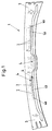
- the Body frame component 1 shows a body frame component 1, namely as a roof rack support trained body component 1 for the body of a motor vehicle.
- the Body frame component 1 has a specific shape typical of a roof rack support and is designed to absorb the forces acting on a roof rack support So when installed, a load-bearing part of the body. Because of the specific Shape of the body frame component 1 exist when these forces are absorbed, that is, then if the body frame component 1 designed as a roof rack support in the roof area a motor vehicle is installed, within different areas 3 and 4 (4a, 4b) of the Body frame component 1 different load or tension conditions.
- first area 3 namely in particular in the edge area, high and in one second area 4 (4a, 4b), namely in particular in the central area of the roof rack support, lower stress or stress conditions.
- the occurring load or Tension states can vary widely in different areas Be pronounced. On the one hand, this depends on the specific form of the Body frame component 1, on the other hand from those in the different areas occurring forces or force components, for example, transverse forces normal forces or bending forces or moments.
- a weight saving on the body frame component 1 is realized in that Area 4 (4a, 4b) of the lower load or tension state for reduction of the material of the body frame component 1 at least one through hole 2, in which Body frame component 1 shown in FIG. 1 has a plurality of through holes 2 are.
- a certain hole pattern is formed through the through holes 2, so that the weight of the body frame component 1 according to that acting on the body frame component 1 Loads is optimized.
- the body frame component 1 by the formation of the Through holes 2 to reduce the material everywhere a substantially the same Can have material thickness.
- the body frame member 1 can thereby in a simple way by one or more forming processes from a flat Material, in particular made of metal boards.
- the through holes 2 can have a certain one Have shape, for example, the through holes 2 can be circular, triangular or be square. Furthermore, the through holes 2 - depending of the occurring loads - have different specific hole diameters. As a result, the shape and the hole diameter of the through holes 2 can be the same as in FIG the body frame component 1 occurring loads are adjusted. Furthermore is determined by the hole spacing of the through holes 2 with each other and a certain one Hole pattern the body frame component 1 according to the loads that occur optimized. For example, the through holes 2 in certain rows - as shown in Fig. 1 shown - can be arranged.
- the through holes 2 are at a certain distance from one Force introduction point of the body frame component 1, in particular in a certain one Distance to hinges, struts, functional surfaces or knots provided, as these areas directly adjacent to a force application point (here areas 3) of the Body frame component 1 are more stressed.
- functional areas can in particular contact surfaces for connection to other components as well as reference surfaces e.g. serve to position the component during production.
- the body frame component 1 shown in FIG. 1 is made of metal, namely from a flat metal plate with constant sheet thickness.
- the Process for producing the body frame component 1 are explained in more detail, whereby - in the end - a three-dimensional body frame component 1 is produced, the - As can be seen schematically from Fig. 1 - a higher area 4a and one lower-lying area 4b has:
- Fig. 2 shows a metal plate 5, which are formed with the help of a forming process can that the body frame member 1 shown in Fig. 1 with that for the roof rack support necessary specific form arises.
- Through holes 2 vzw. a hole diameter of 3 mm and a hole spacing of 3 mm.
- the body frame component 1 in the method for producing a body frame component 1 for the body of a motor vehicle, the body frame component 1 from a essential sheet material formed by the sheet material, usually a Metal board 5, to a specific shape that can be installed inside a body is reshaped.
- the body frame component 1 takes - in the body installed Condition - the forces acting on the body frame component 1, whereby Absorption of these forces due to the specific shape of the body frame component 1 1 different within different areas of the body frame component Load or stress conditions are generated.
- the weight saving for the body frame component 1 and a time saving in the Implementation of the method is realized in that before the forming or during the transformation of the flat material into the specific shape of the Body frame component 1 in the area 4 of the sheet material, in the after Forming - in the installed state of the body frame component 1 - is less Stress or stress condition occurs, at least one through hole 2, here several through holes 2 to reduce the material of the Body frame component 2 are formed.
- the through holes 2 immediately before the forming process for example in a press line at Trimming a metal plate 5 are introduced, so that in addition to punching with a Punching tool no additional process step to form the through holes 2 more is needed.
- the through holes 2 could also during the Forming process are introduced accordingly.
- the procedure is vzw. realized with computer support.
- the forming process is carried out by deep drawing.
- the through holes 2 can be cut prior to deep drawing when trimming the flat Material, here the metal plate 5 shown in FIG. 2 are formed. It is also conceivable that the through holes 2 during deep drawing in the sheet material be formed. The tools necessary for deep drawing could be used for this be trained accordingly.
- the body frame component 1 made from a metal plate 5 has a substantially constant thickness as this is the further treatment and Processing - just without having to consider changes in thickness - essential simplified.
Abstract
Description
- Fig.1
- ein Karosserierahmenbauteil mit einer spezifischen Form gemäß der Erfindung in einer schematischen Darstellung und
- Fig.2
- ein flächiges Material kurz vor dem Umformen zur Herstellung eines Karosserierahmenbauteiles gemäß der Erfindung.
Claims (20)
- Karosserierahmenbauteil (1) für die Karosserie eines Kraftfahrzeuges, wobei das Karosserierahmenbauteil (1) eine spezifische Form aufweist und zur Aufnahme mindestens einer auf das Karosserierahmenbauteil (1) wirkenden Kraft ausgebildet ist, wobei aufgrund der spezifischen Form des Karosserierahmenbauteiles (1) bei Aufnahme dieser Kraft innerhalb verschiedener Bereiche (3,4) des Karosserierahmenbauteiles (1) unterschiedliche Belastungs- bzw. Spannungszustände existieren, insbesondere in einem ersten Bereich (3) hohe und in einem zweiten Bereich (4) geringere Belastungs- bzw. Spannungszustände auftreten, dadurch gekennzeichnet, daß in dem Bereich (4) des geringeren Belastungs- bzw. Spannungszustandes zur Reduzierung des Materials des Karosserierahmenbauteiles (1) mindestens ein Durchgangsloch (2) ausgebildet ist.
- Karosserierahmenbauteil nach dem vorhergehenden Anspruch, dadurch gekennzeichnet, daß in dem Bereich (4) des geringeren Belastungs- bzw. Spannungszustandes mehrere Durchgangslöcher (2) ausgebildet sind.
- Karosserierahmenbauteil nach einem der vorhergehenden Ansprüche, dadurch gekennzeichnet, daß durch die Durchgangslöcher (2) ein bestimmtes Lochmuster gebildet ist.
- Karosserierahmenbauteil nach einem der vorhergehenden Ansprüche, dadurch gekennzeichnet, daß durch das Lochmuster das Gewicht des Karosserierahmenbauteiles (1) gemäß der innerhalb des Karosserierahmenbauteils (1) wirkenden Belastungen optimiert ist.
- Karosserierahmenbauteil nach einem der vorhergehenden Ansprüche, dadurch gekennzeichnet, daß durch bestimmte Lochabstände zwischen den Durchgangslöchern (2) ein gleitender Übergang von einem Bereich eines höheren Belastungs- bzw. Spannungszustandes zu einem Bereich eines geringeren Belastungs- bzw. Spannungszustandes ausgebildet ist.
- Karosserierahmenbauteil nach einem der vorhergehenden Ansprüche, dadurch gekennzeichnet, daß das Karosserierahmenbauteil (1) überall eine im wesentlichen gleiche Materialdicke aufweist.
- Karosserierahmenbauteil nach einem der vorhergehenden Ansprüche, dadurch gekennzeichnet, daß das Durchgangsloch (2) bzw. die Durchgangslöcher (2) eine bestimmte Form aufweist bzw. aufweisen.
- Karosserierahmenbauteil nach einem der vorhergehenden Ansprüche, dadurch gekennzeichnet, daß das Durchgangsloch (2) bzw. die Durchgangslöcher (2) kreisförmig, dreiecksförmig oder viereckig ausgebildet ist bzw. sind.
- Karosserierahmenbauteil nach einem der vorhergehenden Ansprüche, dadurch gekennzeichnet, daß das Durchgangsloch (2) bzw. die Durchgangslöcher (2) einen bestimmten Lochdurchmesser aufweist bzw. aufweisen.
- Karosserierahmenbauteil nach einem der vorhergehenden Ansprüche, dadurch gekennzeichnet, daß die Form und der Lochdurchmesser des Durchgangsloches (2) bzw. der Durchgangslöcher (2) an die in dem Karosserierahmenbauteil (1) auftretenden Belastungen angepaßt ist.
- Karosserierahmenbauteil nach einem der vorhergehenden Ansprüche, dadurch gekennzeichnet, daß das Durchgangsloch (2) bzw. die Durchgangslöcher (2) in einem bestimmten Abstand zu einem Krafteinleitungspunkt des Karosserierahmenbauteiles (1), insbesondere in einem bestimmten Abstand zu Scharnieren, Federbeinen, Funktionsflächen oder Knoten vorgesehen ist bzw. sind.
- Karosserierahmenbauteil nach einem der vorhergehenden Ansprüche, dadurch gekennzeichnet, daß das Karosserierahmenbauteil (1) als Dachträgerstütze ausgeführt ist.
- Karosserierahmenbauteil nach dem vorhergehenden Anspruch, dadurch gekennzeichnet, daß die Durchgangslöcher (2) im mittleren Bereich der Dachträgerstütze ausgebildet sind.
- Karosserierahmenbauteil nach einem der vorhergehenden Ansprüche, dadurch gekennzeichnet, daß das Lochmuster stufenförmig ausgebildet ist.
- Karosserierahmenbauteil nach einem der vorhergehenden Ansprüche, dadurch gekennzeichnet, daß das Karosserierahmenbauteil (1) aus Metall hergestellt ist.
- Verfahren zum Herstellen eines Karosserierahmenbauteiles (1), insbesondere eines Karosserierahmenbauteiles (1) nach einem der Ansprüche 1 bis 15, für die Karosserie eines Kraftfahrzeuges, wobei das Karosserierahmenbauteil (1) aus einem im wesentlichen flächigem Material durch Umformen zu einer innerhalb einer Karosserie einbaubaren spezifischen Form gebildet wird und das Karosserierahmenbauteil (1) - im in der Karosserie eingebauten Zustand - mindestens eine auf das Karosserierahmenbauteil (1) wirkende Kraft aufnimmt, wobei bei Aufnahme dieser Kraft aufgrund der spezifischen Form des Karosserierahmenbauteiles (1) innerhalb verschiedener Bereiche (3,4) des Karosserierahmenbauteiles (1) unterschiedliche Belastungs- bzw. Spannungszustände erzeugt werden, dadurch gekennzeichnet, daß vor dem Umformen oder während des Umformens des flächigen Materials zu der spezifischen Form des Karosserierahmenbauteiles (1) in dem Bereich (4) des flächigen Materials, in dem nach dem Umformen - in eingebautem Zustand des Karosserierahmenbauteiles (1) - ein geringerer Belastungs- bzw. Spannungszustand auftritt, mindestens ein Durchgangsloch (2) zur Reduzierung des Materials des Karosserierahmenbauteiles (1) ausgebildet wird.
- Verfahren zum Herstellen eines Karosserierahmenbauteiles nach Anspruch 16, dadurch gekennzeichnet, daß das Umformen durch Tiefziehen realisiert wird.
- Verfahren zum Herstellen eines Karosserierahmenbauteiles nach Anspruch 16 oder 17, dadurch gekennzeichnet, daß das Durchgangsloch (2) bzw. die Durchgangslöcher (2) vor dem Umformen bei dem Beschnitt des flächigen Materials gebildet wird bzw. werden.
- Verfahren zum Herstellen eines Karosserierahmenbauteiles nach Anspruch 17, dadurch gekennzeichnet, daß das Durchgangsloch (2) bzw. die Durchgangslöcher (2) während des Tiefziehens des flächigen Materials durch die für das Tiefziehen notwendigen Werkzeuge gebildet wird bzw. werden.
- Verfahren zum Herstellen eines Karosserierahmenbauteiles nach einem der Ansprüche 16 bis 19, dadurch gekennzeichnet, daß das Karosserierahmenbauteil (1) aus Metall hergestellt wird.
Applications Claiming Priority (2)
| Application Number | Priority Date | Filing Date | Title |
|---|---|---|---|
| DE19723034A DE19723034C2 (de) | 1997-06-02 | 1997-06-02 | Dachträgerstütze für die Karosserie eines Kraftfahrzeuges und Verfahren für dessen Herstellung |
| DE19723034 | 1997-06-02 |
Publications (3)
| Publication Number | Publication Date |
|---|---|
| EP0882639A2 true EP0882639A2 (de) | 1998-12-09 |
| EP0882639A3 EP0882639A3 (de) | 2000-11-08 |
| EP0882639B1 EP0882639B1 (de) | 2004-01-21 |
Family
ID=7831161
Family Applications (1)
| Application Number | Title | Priority Date | Filing Date |
|---|---|---|---|
| EP98107615A Expired - Lifetime EP0882639B1 (de) | 1997-06-02 | 1998-04-27 | Karosserierahmenbauteil für die Karosserie eines Kraftfahrzeuges und Verfahren für dessen Herstellung |
Country Status (3)
| Country | Link |
|---|---|
| US (1) | US6155634A (de) |
| EP (1) | EP0882639B1 (de) |
| DE (2) | DE19723034C2 (de) |
Families Citing this family (11)
| Publication number | Priority date | Publication date | Assignee | Title |
|---|---|---|---|---|
| DE19837083A1 (de) * | 1998-08-17 | 2000-02-24 | Volkswagen Ag | Karosseriebauteil für die Karosserie eines Kraftfahrzeugs |
| DE19933785A1 (de) * | 1999-07-19 | 2001-01-25 | Volkswagen Ag | Innensäulenelement für die B- oder C-Säule einer Fahrzeugkarosserie |
| DE19948732A1 (de) * | 1999-10-09 | 2001-04-12 | Volkswagen Ag | Fußgängerfreundlich ausgelegtes Kraftfahrzeug-Frontend |
| US7785098B1 (en) | 2001-06-05 | 2010-08-31 | Mikro Systems, Inc. | Systems for large area micro mechanical systems |
| CA2448736C (en) | 2001-06-05 | 2010-08-10 | Mikro Systems, Inc. | Methods for manufacturing three-dimensional devices and devices created thereby |
| US7141812B2 (en) | 2002-06-05 | 2006-11-28 | Mikro Systems, Inc. | Devices, methods, and systems involving castings |
| US20090174229A1 (en) * | 2008-01-03 | 2009-07-09 | Honda Motor Co. Ltd | Stiffened Multi-Part Sunroof |
| US9315663B2 (en) | 2008-09-26 | 2016-04-19 | Mikro Systems, Inc. | Systems, devices, and/or methods for manufacturing castings |
| GB0910615D0 (en) * | 2009-06-19 | 2009-08-05 | Univ Strathclyde | An electrical machine |
| US8813824B2 (en) | 2011-12-06 | 2014-08-26 | Mikro Systems, Inc. | Systems, devices, and/or methods for producing holes |
| DE102019220201B4 (de) | 2019-12-19 | 2022-02-17 | Volkswagen Aktiengesellschaft | Verfahren zur Herstellung eines warmumgeformten und pressgehärteten Stahlblechbauteils |
Citations (2)
| Publication number | Priority date | Publication date | Assignee | Title |
|---|---|---|---|---|
| DE2558332A1 (de) | 1975-12-23 | 1977-07-07 | Porsche Ag | Wandungen, insbesondere fuer aufbauten von fahrzeugen |
| EP0633182B1 (de) | 1993-07-07 | 1997-01-08 | Seb S.A. | Strukturbauteil, insbesondere für Automobile, mit einem verhältnismässig leichten und weichen Metall und Verfahren zur Herstellung |
Family Cites Families (22)
| Publication number | Priority date | Publication date | Assignee | Title |
|---|---|---|---|---|
| DE633182C (de) * | 1936-07-21 | Luebecker Maschb Ges | Fahrgestellrahmen fuer Absetzer, Bagger o. dgl. mit bis zu 140íÒ schwenkbarem Oberbau | |
| BE346379A (de) * | 1927-01-08 | |||
| FR647792A (fr) * | 1927-03-08 | 1928-11-30 | Budd Edward G Mfg Co | Construction de toit pour automobiles et autres véhicules |
| GB422698A (en) * | 1933-10-28 | 1935-01-16 | Short Brothers Rochester & Bedford Ltd | Improvements in or relating to the construction of vehicle bodies |
| US2157649A (en) * | 1934-05-31 | 1939-05-09 | Budd Edward G Mfg Co | Combined body and chassis construction |
| US2138084A (en) * | 1934-07-26 | 1938-11-29 | Packard Motor Car Co | Motor vehicle |
| US2155503A (en) * | 1935-01-19 | 1939-04-25 | Packard Motor Car Co | Motor vehicle |
| US2164097A (en) * | 1936-12-07 | 1939-06-27 | Briggs Mfg Co | Automobile body |
| US2164098A (en) * | 1937-10-22 | 1939-06-27 | Briggs Mfg Co | Automobile body |
| BE487370A (de) * | 1948-04-07 | |||
| DE2160537A1 (de) * | 1971-12-07 | 1973-06-14 | Daimler Benz Ag | Kraftfahrzeugdach, insbesondere von personenkraftwagen |
| US4834448A (en) * | 1987-03-03 | 1989-05-30 | Mazda Motor Corporation | Structure for mounting roof carriers on a roof of motorcar |
| DE3809456C2 (de) * | 1987-03-27 | 1995-06-14 | Nissan Motor | Fahrzeugaufbau und Verfahren zur Herstellung desselben |
| US4867362A (en) * | 1988-07-28 | 1989-09-19 | The Shelburne Corporation | Multipurpose car-top rack |
| US4950026A (en) * | 1988-10-06 | 1990-08-21 | Emmons J Bruce | Passenger vehicle body frame |
| US5370438A (en) * | 1991-10-31 | 1994-12-06 | Toyota Jidosha Kabushiki Kaisha | Structural member of automobile |
| JPH067874A (ja) * | 1992-06-29 | 1994-01-18 | Showa Alum Corp | 部分的に厚さの異なる押出二次加工品の製造方法 |
| DE4440192C2 (de) * | 1993-11-23 | 2002-01-10 | Volkswagen Ag | Akustisch bedämpftes Strukturteil |
| DE4405904C1 (de) * | 1994-02-24 | 1995-05-04 | Porsche Ag | Crashgünstige Aggregatlagerung |
| JPH08164869A (ja) * | 1994-12-15 | 1996-06-25 | Fuji Heavy Ind Ltd | 車両の前部フレーム構造 |
| DE19545591C1 (de) * | 1995-12-07 | 1997-04-10 | Alusuisse Lonza Services Ag | Fahrzeug, insbesondere Straßen- oder Schienenfahrzeug, mit einem Skelett |
| JP3198960B2 (ja) * | 1996-04-04 | 2001-08-13 | トヨタ自動車株式会社 | 車両の下部車体構造 |
-
1997
- 1997-06-02 DE DE19723034A patent/DE19723034C2/de not_active Expired - Fee Related
-
1998
- 1998-04-27 EP EP98107615A patent/EP0882639B1/de not_active Expired - Lifetime
- 1998-04-27 DE DE59810615T patent/DE59810615D1/de not_active Expired - Lifetime
- 1998-06-02 US US09/088,286 patent/US6155634A/en not_active Expired - Lifetime
Patent Citations (2)
| Publication number | Priority date | Publication date | Assignee | Title |
|---|---|---|---|---|
| DE2558332A1 (de) | 1975-12-23 | 1977-07-07 | Porsche Ag | Wandungen, insbesondere fuer aufbauten von fahrzeugen |
| EP0633182B1 (de) | 1993-07-07 | 1997-01-08 | Seb S.A. | Strukturbauteil, insbesondere für Automobile, mit einem verhältnismässig leichten und weichen Metall und Verfahren zur Herstellung |
Also Published As
| Publication number | Publication date |
|---|---|
| EP0882639A3 (de) | 2000-11-08 |
| EP0882639B1 (de) | 2004-01-21 |
| DE59810615D1 (de) | 2004-02-26 |
| DE19723034C2 (de) | 2003-02-20 |
| DE19723034A1 (de) | 1998-12-03 |
| US6155634A (en) | 2000-12-05 |
Similar Documents
| Publication | Publication Date | Title |
|---|---|---|
| EP2025560B1 (de) | Verfahren zur Herstellung einer Stossfängeranordnung eines Kraftfahrzeugs | |
| DE202016103279U1 (de) | Sechzehneckiges Verstärkungselement für Fahrzeuge | |
| EP1838488A1 (de) | Verfahren zum zusammenfügen zumindest eines ersten bleches und eines zweiten bleches mittels laserschweissen, verfahren zum zusammenfügen zumindest dreier bleche mittels laserschweissen, verwendung der verfahren und bauteil, gefertigt mittels der verfahren | |
| DE102006025522B4 (de) | Verfahren und Vorrichtung zur Herstellung strukturierter, geschlossener Hohlprofile | |
| DE10208778A1 (de) | Aus Stahl-Hohlprofilen gebildete Tragstruktur für Fahrzeuge | |
| DE19519779A1 (de) | Rahmenseitenteil einer Karosserie von Kraftfahrzeugen, insbesondere Personenkraftwagen, und Verfahren zu dessen Herstellung | |
| DE102007038036B4 (de) | Verfahren zur Herstellung eines rohrförmigen Tragprofils für einen Instrumententräger | |
| DE19723034C2 (de) | Dachträgerstütze für die Karosserie eines Kraftfahrzeuges und Verfahren für dessen Herstellung | |
| WO2005075279A1 (de) | Bautell mit einem verbindungsbereich, sowie verfahren und werkzeug zu seiner herstellung | |
| DE10006348C2 (de) | Bauteil mit lokal begrenzten Versteifungsbereichen und Verfahren zu seiner Herstellung | |
| DE102011052153A1 (de) | Verfahren zur Herstellung eines Kraftfahrzeug-Biegeträgers und Kraftfahrzeug-Biegeträger | |
| EP3901006A1 (de) | Kraftfahrzeugbauteil | |
| DE10303184B3 (de) | Verfahren und Vorrichtung zur Herstellung von einer in ihrer Dicke mindestens in einem Bereich variierenden Platine | |
| DE60214659T2 (de) | Gesamtstruktur eines Armaturenbrettes und Verfahren zu dessen Herstellung | |
| DE102005031728A1 (de) | Tragstruktur einer Karosserie und Verfahren zum Herstellen einer derartigen Tragstruktur | |
| DE4134596C2 (de) | ||
| DE19742818A1 (de) | Platine für ein Strukturbauteil, Strukturbauteil und Verfahren zur Herstellung eines Strukturbauteiles für Kraftfahrzeuge | |
| DE102006008212B4 (de) | Druckgussbauteil insbesondere für eine Karosserie oder ein Fahrwerk eines Kraftwagens sowie Verfahren zu seiner Herstellung | |
| DE102011052291B4 (de) | Kraftfahrzeugbauteil sowie Verfahren zur Herstellung eines Kraftfahrzeugbauteils | |
| EP0904868B1 (de) | Strukturbauteil und Verfahren zur Herstellung eines Strukturbauteils für Kraftfahrzeuge | |
| EP1357017B1 (de) | Rahmenstruktur eines Fahrzeugs | |
| DE10103487A1 (de) | Verfahren zur Herstellung eines großflächigen Gebildes an Kraftfahrzeugen und großflächiges Gebilde dazu | |
| DE19837083A1 (de) | Karosseriebauteil für die Karosserie eines Kraftfahrzeugs | |
| DE102006019479B4 (de) | Türaufbau mit Tailored Blanks | |
| DE10043880A1 (de) | Stossfänger |
Legal Events
| Date | Code | Title | Description |
|---|---|---|---|
| PUAI | Public reference made under article 153(3) epc to a published international application that has entered the european phase |
Free format text: ORIGINAL CODE: 0009012 |
|
| AK | Designated contracting states |
Kind code of ref document: A2 Designated state(s): DE ES FR GB IT SE |
|
| AX | Request for extension of the european patent |
Free format text: AL;LT;LV;MK;RO;SI |
|
| PUAL | Search report despatched |
Free format text: ORIGINAL CODE: 0009013 |
|
| AK | Designated contracting states |
Kind code of ref document: A3 Designated state(s): AT BE CH CY DE DK ES FI FR GB GR IE IT LI LU MC NL PT SE |
|
| AX | Request for extension of the european patent |
Free format text: AL;LT;LV;MK;RO;SI |
|
| RIC1 | Information provided on ipc code assigned before grant |
Free format text: 7B 62D 25/00 A, 7B 62D 25/06 B, 7B 62D 25/02 B, 7B 62D 25/10 B |
|
| 17P | Request for examination filed |
Effective date: 20010508 |
|
| AKX | Designation fees paid |
Free format text: DE ES FR GB IT SE |
|
| 17Q | First examination report despatched |
Effective date: 20021113 |
|
| GRAH | Despatch of communication of intention to grant a patent |
Free format text: ORIGINAL CODE: EPIDOS IGRA |
|
| GRAS | Grant fee paid |
Free format text: ORIGINAL CODE: EPIDOSNIGR3 |
|
| GRAA | (expected) grant |
Free format text: ORIGINAL CODE: 0009210 |
|
| AK | Designated contracting states |
Kind code of ref document: B1 Designated state(s): DE ES FR GB IT SE |
|
| PG25 | Lapsed in a contracting state [announced via postgrant information from national office to epo] |
Ref country code: IT Free format text: LAPSE BECAUSE OF FAILURE TO SUBMIT A TRANSLATION OF THE DESCRIPTION OR TO PAY THE FEE WITHIN THE PRE;WARNING: LAPSES OF ITALIAN PATENTS WITH EFFECTIVE DATE BEFORE 2007 MAY HAVE OCCURRED AT ANY TIME BEFORE 2007. THE CORRECT EFFECTIVE DATE MAY BE DIFFERENT FROM THE ONE RECORDED.SCRIBED TIME-LIMIT Effective date: 20040121 Ref country code: GB Free format text: LAPSE BECAUSE OF FAILURE TO SUBMIT A TRANSLATION OF THE DESCRIPTION OR TO PAY THE FEE WITHIN THE PRESCRIBED TIME-LIMIT Effective date: 20040121 |
|
| REG | Reference to a national code |
Ref country code: GB Ref legal event code: FG4D Free format text: NOT ENGLISH |
|
| REF | Corresponds to: |
Ref document number: 59810615 Country of ref document: DE Date of ref document: 20040226 Kind code of ref document: P |
|
| PG25 | Lapsed in a contracting state [announced via postgrant information from national office to epo] |
Ref country code: SE Free format text: LAPSE BECAUSE OF FAILURE TO SUBMIT A TRANSLATION OF THE DESCRIPTION OR TO PAY THE FEE WITHIN THE PRESCRIBED TIME-LIMIT Effective date: 20040421 |
|
| PG25 | Lapsed in a contracting state [announced via postgrant information from national office to epo] |
Ref country code: ES Free format text: LAPSE BECAUSE OF FAILURE TO SUBMIT A TRANSLATION OF THE DESCRIPTION OR TO PAY THE FEE WITHIN THE PRESCRIBED TIME-LIMIT Effective date: 20040502 |
|
| GBV | Gb: ep patent (uk) treated as always having been void in accordance with gb section 77(7)/1977 [no translation filed] |
Effective date: 20040121 |
|
| ET | Fr: translation filed | ||
| PLBE | No opposition filed within time limit |
Free format text: ORIGINAL CODE: 0009261 |
|
| STAA | Information on the status of an ep patent application or granted ep patent |
Free format text: STATUS: NO OPPOSITION FILED WITHIN TIME LIMIT |
|
| 26N | No opposition filed |
Effective date: 20041022 |
|
| PGFP | Annual fee paid to national office [announced via postgrant information from national office to epo] |
Ref country code: DE Payment date: 20130430 Year of fee payment: 16 |
|
| PGFP | Annual fee paid to national office [announced via postgrant information from national office to epo] |
Ref country code: FR Payment date: 20130612 Year of fee payment: 16 |
|
| REG | Reference to a national code |
Ref country code: DE Ref legal event code: R119 Ref document number: 59810615 Country of ref document: DE |
|
| REG | Reference to a national code |
Ref country code: FR Ref legal event code: ST Effective date: 20141231 |
|
| REG | Reference to a national code |
Ref country code: DE Ref legal event code: R119 Ref document number: 59810615 Country of ref document: DE Effective date: 20141101 |
|
| PG25 | Lapsed in a contracting state [announced via postgrant information from national office to epo] |
Ref country code: DE Free format text: LAPSE BECAUSE OF NON-PAYMENT OF DUE FEES Effective date: 20141101 |
|
| PG25 | Lapsed in a contracting state [announced via postgrant information from national office to epo] |
Ref country code: FR Free format text: LAPSE BECAUSE OF NON-PAYMENT OF DUE FEES Effective date: 20140430 |