EP0884833B1 - Variable speed wind turbine - Google Patents
Variable speed wind turbine Download PDFInfo
- Publication number
- EP0884833B1 EP0884833B1 EP98111304A EP98111304A EP0884833B1 EP 0884833 B1 EP0884833 B1 EP 0884833B1 EP 98111304 A EP98111304 A EP 98111304A EP 98111304 A EP98111304 A EP 98111304A EP 0884833 B1 EP0884833 B1 EP 0884833B1
- Authority
- EP
- European Patent Office
- Prior art keywords
- stator
- rotor
- torque
- generator
- wind turbine
- Prior art date
- Legal status (The legal status is an assumption and is not a legal conclusion. Google has not performed a legal analysis and makes no representation as to the accuracy of the status listed.)
- Revoked
Links
- 230000004907 flux Effects 0.000 claims description 68
- 239000013598 vector Substances 0.000 claims description 40
- 238000000034 method Methods 0.000 claims description 29
- 238000006243 chemical reaction Methods 0.000 claims description 12
- 230000009466 transformation Effects 0.000 claims description 9
- 238000004804 winding Methods 0.000 claims description 7
- 238000006880 cross-coupling reaction Methods 0.000 claims description 3
- 238000012544 monitoring process Methods 0.000 claims description 3
- 230000001131 transforming effect Effects 0.000 claims description 3
- 238000010586 diagram Methods 0.000 description 16
- 238000004364 calculation method Methods 0.000 description 7
- 230000006698 induction Effects 0.000 description 7
- 238000004590 computer program Methods 0.000 description 6
- 230000005611 electricity Effects 0.000 description 4
- 230000005540 biological transmission Effects 0.000 description 3
- 230000008878 coupling Effects 0.000 description 3
- 238000010168 coupling process Methods 0.000 description 3
- 238000005859 coupling reaction Methods 0.000 description 3
- 230000000694 effects Effects 0.000 description 3
- 230000014509 gene expression Effects 0.000 description 3
- 230000004044 response Effects 0.000 description 3
- 230000001360 synchronised effect Effects 0.000 description 3
- 238000013459 approach Methods 0.000 description 2
- 239000003990 capacitor Substances 0.000 description 2
- 230000000295 complement effect Effects 0.000 description 2
- 238000012937 correction Methods 0.000 description 2
- 238000004146 energy storage Methods 0.000 description 2
- 239000011159 matrix material Substances 0.000 description 2
- 230000003287 optical effect Effects 0.000 description 2
- 230000010355 oscillation Effects 0.000 description 2
- 238000011084 recovery Methods 0.000 description 2
- XUIMIQQOPSSXEZ-UHFFFAOYSA-N Silicon Chemical compound [Si] XUIMIQQOPSSXEZ-UHFFFAOYSA-N 0.000 description 1
- 230000008859 change Effects 0.000 description 1
- 230000001419 dependent effect Effects 0.000 description 1
- 238000013461 design Methods 0.000 description 1
- 230000005669 field effect Effects 0.000 description 1
- 238000005259 measurement Methods 0.000 description 1
- 230000000737 periodic effect Effects 0.000 description 1
- 238000000819 phase cycle Methods 0.000 description 1
- 229910052710 silicon Inorganic materials 0.000 description 1
- 239000010703 silicon Substances 0.000 description 1
- 230000003068 static effect Effects 0.000 description 1
- 238000000844 transformation Methods 0.000 description 1
- 230000003313 weakening effect Effects 0.000 description 1
Images


Classifications
-
- F—MECHANICAL ENGINEERING; LIGHTING; HEATING; WEAPONS; BLASTING
- F03—MACHINES OR ENGINES FOR LIQUIDS; WIND, SPRING, OR WEIGHT MOTORS; PRODUCING MECHANICAL POWER OR A REACTIVE PROPULSIVE THRUST, NOT OTHERWISE PROVIDED FOR
- F03D—WIND MOTORS
- F03D7/00—Controlling wind motors
- F03D7/02—Controlling wind motors the wind motors having rotation axis substantially parallel to the air flow entering the rotor
- F03D7/0272—Controlling wind motors the wind motors having rotation axis substantially parallel to the air flow entering the rotor by measures acting on the electrical generator
-
- F—MECHANICAL ENGINEERING; LIGHTING; HEATING; WEAPONS; BLASTING
- F03—MACHINES OR ENGINES FOR LIQUIDS; WIND, SPRING, OR WEIGHT MOTORS; PRODUCING MECHANICAL POWER OR A REACTIVE PROPULSIVE THRUST, NOT OTHERWISE PROVIDED FOR
- F03D—WIND MOTORS
- F03D7/00—Controlling wind motors
- F03D7/02—Controlling wind motors the wind motors having rotation axis substantially parallel to the air flow entering the rotor
- F03D7/0276—Controlling wind motors the wind motors having rotation axis substantially parallel to the air flow entering the rotor controlling rotor speed, e.g. variable speed
-
- F—MECHANICAL ENGINEERING; LIGHTING; HEATING; WEAPONS; BLASTING
- F03—MACHINES OR ENGINES FOR LIQUIDS; WIND, SPRING, OR WEIGHT MOTORS; PRODUCING MECHANICAL POWER OR A REACTIVE PROPULSIVE THRUST, NOT OTHERWISE PROVIDED FOR
- F03D—WIND MOTORS
- F03D7/00—Controlling wind motors
- F03D7/02—Controlling wind motors the wind motors having rotation axis substantially parallel to the air flow entering the rotor
- F03D7/04—Automatic control; Regulation
- F03D7/042—Automatic control; Regulation by means of an electrical or electronic controller
-
- F—MECHANICAL ENGINEERING; LIGHTING; HEATING; WEAPONS; BLASTING
- F03—MACHINES OR ENGINES FOR LIQUIDS; WIND, SPRING, OR WEIGHT MOTORS; PRODUCING MECHANICAL POWER OR A REACTIVE PROPULSIVE THRUST, NOT OTHERWISE PROVIDED FOR
- F03D—WIND MOTORS
- F03D9/00—Adaptations of wind motors for special use; Combinations of wind motors with apparatus driven thereby; Wind motors specially adapted for installation in particular locations
- F03D9/20—Wind motors characterised by the driven apparatus
- F03D9/25—Wind motors characterised by the driven apparatus the apparatus being an electrical generator
- F03D9/255—Wind motors characterised by the driven apparatus the apparatus being an electrical generator connected to electrical distribution networks; Arrangements therefor
-
- H—ELECTRICITY
- H02—GENERATION; CONVERSION OR DISTRIBUTION OF ELECTRIC POWER
- H02J—CIRCUIT ARRANGEMENTS OR SYSTEMS FOR SUPPLYING OR DISTRIBUTING ELECTRIC POWER; SYSTEMS FOR STORING ELECTRIC ENERGY
- H02J3/00—Circuit arrangements for ac mains or ac distribution networks
- H02J3/18—Arrangements for adjusting, eliminating or compensating reactive power in networks
- H02J3/1821—Arrangements for adjusting, eliminating or compensating reactive power in networks using shunt compensators
- H02J3/1835—Arrangements for adjusting, eliminating or compensating reactive power in networks using shunt compensators with stepless control
- H02J3/1842—Arrangements for adjusting, eliminating or compensating reactive power in networks using shunt compensators with stepless control wherein at least one reactive element is actively controlled by a bridge converter, e.g. active filters
-
- H—ELECTRICITY
- H02—GENERATION; CONVERSION OR DISTRIBUTION OF ELECTRIC POWER
- H02J—CIRCUIT ARRANGEMENTS OR SYSTEMS FOR SUPPLYING OR DISTRIBUTING ELECTRIC POWER; SYSTEMS FOR STORING ELECTRIC ENERGY
- H02J3/00—Circuit arrangements for ac mains or ac distribution networks
- H02J3/18—Arrangements for adjusting, eliminating or compensating reactive power in networks
- H02J3/1892—Arrangements for adjusting, eliminating or compensating reactive power in networks the arrangements being an integral part of the load, e.g. a motor, or of its control circuit
-
- H—ELECTRICITY
- H02—GENERATION; CONVERSION OR DISTRIBUTION OF ELECTRIC POWER
- H02J—CIRCUIT ARRANGEMENTS OR SYSTEMS FOR SUPPLYING OR DISTRIBUTING ELECTRIC POWER; SYSTEMS FOR STORING ELECTRIC ENERGY
- H02J3/00—Circuit arrangements for ac mains or ac distribution networks
- H02J3/38—Arrangements for parallely feeding a single network by two or more generators, converters or transformers
- H02J3/381—Dispersed generators
-
- H—ELECTRICITY
- H02—GENERATION; CONVERSION OR DISTRIBUTION OF ELECTRIC POWER
- H02P—CONTROL OR REGULATION OF ELECTRIC MOTORS, ELECTRIC GENERATORS OR DYNAMO-ELECTRIC CONVERTERS; CONTROLLING TRANSFORMERS, REACTORS OR CHOKE COILS
- H02P21/00—Arrangements or methods for the control of electric machines by vector control, e.g. by control of field orientation
- H02P21/06—Rotor flux based control involving the use of rotor position or rotor speed sensors
-
- H—ELECTRICITY
- H02—GENERATION; CONVERSION OR DISTRIBUTION OF ELECTRIC POWER
- H02P—CONTROL OR REGULATION OF ELECTRIC MOTORS, ELECTRIC GENERATORS OR DYNAMO-ELECTRIC CONVERTERS; CONTROLLING TRANSFORMERS, REACTORS OR CHOKE COILS
- H02P9/00—Arrangements for controlling electric generators for the purpose of obtaining a desired output
- H02P9/04—Control effected upon non-electric prime mover and dependent upon electric output value of the generator
-
- H—ELECTRICITY
- H02—GENERATION; CONVERSION OR DISTRIBUTION OF ELECTRIC POWER
- H02P—CONTROL OR REGULATION OF ELECTRIC MOTORS, ELECTRIC GENERATORS OR DYNAMO-ELECTRIC CONVERTERS; CONTROLLING TRANSFORMERS, REACTORS OR CHOKE COILS
- H02P9/00—Arrangements for controlling electric generators for the purpose of obtaining a desired output
- H02P9/42—Arrangements for controlling electric generators for the purpose of obtaining a desired output to obtain desired frequency without varying speed of the generator
-
- H—ELECTRICITY
- H02—GENERATION; CONVERSION OR DISTRIBUTION OF ELECTRIC POWER
- H02P—CONTROL OR REGULATION OF ELECTRIC MOTORS, ELECTRIC GENERATORS OR DYNAMO-ELECTRIC CONVERTERS; CONTROLLING TRANSFORMERS, REACTORS OR CHOKE COILS
- H02P9/00—Arrangements for controlling electric generators for the purpose of obtaining a desired output
- H02P9/48—Arrangements for obtaining a constant output value at varying speed of the generator, e.g. on vehicle
-
- F—MECHANICAL ENGINEERING; LIGHTING; HEATING; WEAPONS; BLASTING
- F05—INDEXING SCHEMES RELATING TO ENGINES OR PUMPS IN VARIOUS SUBCLASSES OF CLASSES F01-F04
- F05B—INDEXING SCHEME RELATING TO WIND, SPRING, WEIGHT, INERTIA OR LIKE MOTORS, TO MACHINES OR ENGINES FOR LIQUIDS COVERED BY SUBCLASSES F03B, F03D AND F03G
- F05B2220/00—Application
- F05B2220/70—Application in combination with
- F05B2220/706—Application in combination with an electrical generator
- F05B2220/7064—Application in combination with an electrical generator of the alternating current (A.C.) type
-
- F—MECHANICAL ENGINEERING; LIGHTING; HEATING; WEAPONS; BLASTING
- F05—INDEXING SCHEMES RELATING TO ENGINES OR PUMPS IN VARIOUS SUBCLASSES OF CLASSES F01-F04
- F05B—INDEXING SCHEME RELATING TO WIND, SPRING, WEIGHT, INERTIA OR LIKE MOTORS, TO MACHINES OR ENGINES FOR LIQUIDS COVERED BY SUBCLASSES F03B, F03D AND F03G
- F05B2270/00—Control
- F05B2270/10—Purpose of the control system
- F05B2270/1016—Purpose of the control system in variable speed operation
-
- F—MECHANICAL ENGINEERING; LIGHTING; HEATING; WEAPONS; BLASTING
- F05—INDEXING SCHEMES RELATING TO ENGINES OR PUMPS IN VARIOUS SUBCLASSES OF CLASSES F01-F04
- F05B—INDEXING SCHEME RELATING TO WIND, SPRING, WEIGHT, INERTIA OR LIKE MOTORS, TO MACHINES OR ENGINES FOR LIQUIDS COVERED BY SUBCLASSES F03B, F03D AND F03G
- F05B2270/00—Control
- F05B2270/10—Purpose of the control system
- F05B2270/103—Purpose of the control system to affect the output of the engine
- F05B2270/1032—Torque
-
- F—MECHANICAL ENGINEERING; LIGHTING; HEATING; WEAPONS; BLASTING
- F05—INDEXING SCHEMES RELATING TO ENGINES OR PUMPS IN VARIOUS SUBCLASSES OF CLASSES F01-F04
- F05B—INDEXING SCHEME RELATING TO WIND, SPRING, WEIGHT, INERTIA OR LIKE MOTORS, TO MACHINES OR ENGINES FOR LIQUIDS COVERED BY SUBCLASSES F03B, F03D AND F03G
- F05B2270/00—Control
- F05B2270/10—Purpose of the control system
- F05B2270/104—Purpose of the control system to match engine to driven device
-
- F—MECHANICAL ENGINEERING; LIGHTING; HEATING; WEAPONS; BLASTING
- F05—INDEXING SCHEMES RELATING TO ENGINES OR PUMPS IN VARIOUS SUBCLASSES OF CLASSES F01-F04
- F05B—INDEXING SCHEME RELATING TO WIND, SPRING, WEIGHT, INERTIA OR LIKE MOTORS, TO MACHINES OR ENGINES FOR LIQUIDS COVERED BY SUBCLASSES F03B, F03D AND F03G
- F05B2270/00—Control
- F05B2270/10—Purpose of the control system
- F05B2270/20—Purpose of the control system to optimise the performance of a machine
-
- F—MECHANICAL ENGINEERING; LIGHTING; HEATING; WEAPONS; BLASTING
- F05—INDEXING SCHEMES RELATING TO ENGINES OR PUMPS IN VARIOUS SUBCLASSES OF CLASSES F01-F04
- F05B—INDEXING SCHEME RELATING TO WIND, SPRING, WEIGHT, INERTIA OR LIKE MOTORS, TO MACHINES OR ENGINES FOR LIQUIDS COVERED BY SUBCLASSES F03B, F03D AND F03G
- F05B2270/00—Control
- F05B2270/30—Control parameters, e.g. input parameters
- F05B2270/327—Rotor or generator speeds
-
- F—MECHANICAL ENGINEERING; LIGHTING; HEATING; WEAPONS; BLASTING
- F05—INDEXING SCHEMES RELATING TO ENGINES OR PUMPS IN VARIOUS SUBCLASSES OF CLASSES F01-F04
- F05B—INDEXING SCHEME RELATING TO WIND, SPRING, WEIGHT, INERTIA OR LIKE MOTORS, TO MACHINES OR ENGINES FOR LIQUIDS COVERED BY SUBCLASSES F03B, F03D AND F03G
- F05B2270/00—Control
- F05B2270/30—Control parameters, e.g. input parameters
- F05B2270/328—Blade pitch angle
-
- F—MECHANICAL ENGINEERING; LIGHTING; HEATING; WEAPONS; BLASTING
- F05—INDEXING SCHEMES RELATING TO ENGINES OR PUMPS IN VARIOUS SUBCLASSES OF CLASSES F01-F04
- F05B—INDEXING SCHEME RELATING TO WIND, SPRING, WEIGHT, INERTIA OR LIKE MOTORS, TO MACHINES OR ENGINES FOR LIQUIDS COVERED BY SUBCLASSES F03B, F03D AND F03G
- F05B2270/00—Control
- F05B2270/30—Control parameters, e.g. input parameters
- F05B2270/335—Output power or torque
-
- H—ELECTRICITY
- H02—GENERATION; CONVERSION OR DISTRIBUTION OF ELECTRIC POWER
- H02J—CIRCUIT ARRANGEMENTS OR SYSTEMS FOR SUPPLYING OR DISTRIBUTING ELECTRIC POWER; SYSTEMS FOR STORING ELECTRIC ENERGY
- H02J2300/00—Systems for supplying or distributing electric power characterised by decentralized, dispersed, or local generation
- H02J2300/20—The dispersed energy generation being of renewable origin
- H02J2300/28—The renewable source being wind energy
-
- H—ELECTRICITY
- H02—GENERATION; CONVERSION OR DISTRIBUTION OF ELECTRIC POWER
- H02J—CIRCUIT ARRANGEMENTS OR SYSTEMS FOR SUPPLYING OR DISTRIBUTING ELECTRIC POWER; SYSTEMS FOR STORING ELECTRIC ENERGY
- H02J3/00—Circuit arrangements for ac mains or ac distribution networks
- H02J3/38—Arrangements for parallely feeding a single network by two or more generators, converters or transformers
- H02J3/40—Synchronising a generator for connection to a network or to another generator
-
- H—ELECTRICITY
- H02—GENERATION; CONVERSION OR DISTRIBUTION OF ELECTRIC POWER
- H02M—APPARATUS FOR CONVERSION BETWEEN AC AND AC, BETWEEN AC AND DC, OR BETWEEN DC AND DC, AND FOR USE WITH MAINS OR SIMILAR POWER SUPPLY SYSTEMS; CONVERSION OF DC OR AC INPUT POWER INTO SURGE OUTPUT POWER; CONTROL OR REGULATION THEREOF
- H02M7/00—Conversion of ac power input into dc power output; Conversion of dc power input into ac power output
- H02M7/42—Conversion of dc power input into ac power output without possibility of reversal
- H02M7/44—Conversion of dc power input into ac power output without possibility of reversal by static converters
- H02M7/48—Conversion of dc power input into ac power output without possibility of reversal by static converters using discharge tubes with control electrode or semiconductor devices with control electrode
- H02M7/53—Conversion of dc power input into ac power output without possibility of reversal by static converters using discharge tubes with control electrode or semiconductor devices with control electrode using devices of a triode or transistor type requiring continuous application of a control signal
- H02M7/537—Conversion of dc power input into ac power output without possibility of reversal by static converters using discharge tubes with control electrode or semiconductor devices with control electrode using devices of a triode or transistor type requiring continuous application of a control signal using semiconductor devices only, e.g. single switched pulse inverters
- H02M7/5387—Conversion of dc power input into ac power output without possibility of reversal by static converters using discharge tubes with control electrode or semiconductor devices with control electrode using devices of a triode or transistor type requiring continuous application of a control signal using semiconductor devices only, e.g. single switched pulse inverters in a bridge configuration
- H02M7/53871—Conversion of dc power input into ac power output without possibility of reversal by static converters using discharge tubes with control electrode or semiconductor devices with control electrode using devices of a triode or transistor type requiring continuous application of a control signal using semiconductor devices only, e.g. single switched pulse inverters in a bridge configuration with automatic control of output voltage or current
- H02M7/53875—Conversion of dc power input into ac power output without possibility of reversal by static converters using discharge tubes with control electrode or semiconductor devices with control electrode using devices of a triode or transistor type requiring continuous application of a control signal using semiconductor devices only, e.g. single switched pulse inverters in a bridge configuration with automatic control of output voltage or current with analogue control of three-phase output
- H02M7/53876—Conversion of dc power input into ac power output without possibility of reversal by static converters using discharge tubes with control electrode or semiconductor devices with control electrode using devices of a triode or transistor type requiring continuous application of a control signal using semiconductor devices only, e.g. single switched pulse inverters in a bridge configuration with automatic control of output voltage or current with analogue control of three-phase output based on synthesising a desired voltage vector via the selection of appropriate fundamental voltage vectors, and corresponding dwelling times
-
- H—ELECTRICITY
- H02—GENERATION; CONVERSION OR DISTRIBUTION OF ELECTRIC POWER
- H02P—CONTROL OR REGULATION OF ELECTRIC MOTORS, ELECTRIC GENERATORS OR DYNAMO-ELECTRIC CONVERTERS; CONTROLLING TRANSFORMERS, REACTORS OR CHOKE COILS
- H02P2101/00—Special adaptation of control arrangements for generators
- H02P2101/15—Special adaptation of control arrangements for generators for wind-driven turbines
-
- Y—GENERAL TAGGING OF NEW TECHNOLOGICAL DEVELOPMENTS; GENERAL TAGGING OF CROSS-SECTIONAL TECHNOLOGIES SPANNING OVER SEVERAL SECTIONS OF THE IPC; TECHNICAL SUBJECTS COVERED BY FORMER USPC CROSS-REFERENCE ART COLLECTIONS [XRACs] AND DIGESTS
- Y02—TECHNOLOGIES OR APPLICATIONS FOR MITIGATION OR ADAPTATION AGAINST CLIMATE CHANGE
- Y02E—REDUCTION OF GREENHOUSE GAS [GHG] EMISSIONS, RELATED TO ENERGY GENERATION, TRANSMISSION OR DISTRIBUTION
- Y02E10/00—Energy generation through renewable energy sources
- Y02E10/50—Photovoltaic [PV] energy
- Y02E10/56—Power conversion systems, e.g. maximum power point trackers
-
- Y—GENERAL TAGGING OF NEW TECHNOLOGICAL DEVELOPMENTS; GENERAL TAGGING OF CROSS-SECTIONAL TECHNOLOGIES SPANNING OVER SEVERAL SECTIONS OF THE IPC; TECHNICAL SUBJECTS COVERED BY FORMER USPC CROSS-REFERENCE ART COLLECTIONS [XRACs] AND DIGESTS
- Y02—TECHNOLOGIES OR APPLICATIONS FOR MITIGATION OR ADAPTATION AGAINST CLIMATE CHANGE
- Y02E—REDUCTION OF GREENHOUSE GAS [GHG] EMISSIONS, RELATED TO ENERGY GENERATION, TRANSMISSION OR DISTRIBUTION
- Y02E10/00—Energy generation through renewable energy sources
- Y02E10/70—Wind energy
- Y02E10/72—Wind turbines with rotation axis in wind direction
-
- Y—GENERAL TAGGING OF NEW TECHNOLOGICAL DEVELOPMENTS; GENERAL TAGGING OF CROSS-SECTIONAL TECHNOLOGIES SPANNING OVER SEVERAL SECTIONS OF THE IPC; TECHNICAL SUBJECTS COVERED BY FORMER USPC CROSS-REFERENCE ART COLLECTIONS [XRACs] AND DIGESTS
- Y02—TECHNOLOGIES OR APPLICATIONS FOR MITIGATION OR ADAPTATION AGAINST CLIMATE CHANGE
- Y02E—REDUCTION OF GREENHOUSE GAS [GHG] EMISSIONS, RELATED TO ENERGY GENERATION, TRANSMISSION OR DISTRIBUTION
- Y02E10/00—Energy generation through renewable energy sources
- Y02E10/70—Wind energy
- Y02E10/76—Power conversion electric or electronic aspects
-
- Y—GENERAL TAGGING OF NEW TECHNOLOGICAL DEVELOPMENTS; GENERAL TAGGING OF CROSS-SECTIONAL TECHNOLOGIES SPANNING OVER SEVERAL SECTIONS OF THE IPC; TECHNICAL SUBJECTS COVERED BY FORMER USPC CROSS-REFERENCE ART COLLECTIONS [XRACs] AND DIGESTS
- Y02—TECHNOLOGIES OR APPLICATIONS FOR MITIGATION OR ADAPTATION AGAINST CLIMATE CHANGE
- Y02E—REDUCTION OF GREENHOUSE GAS [GHG] EMISSIONS, RELATED TO ENERGY GENERATION, TRANSMISSION OR DISTRIBUTION
- Y02E40/00—Technologies for an efficient electrical power generation, transmission or distribution
- Y02E40/20—Active power filtering [APF]
Definitions
- This invention relates generally to wind turbines that operate at variable speed under varying wind conditions, and relates more particularly to a power converter for converting wind energy into AC electrical power at a controlled power factor and for controlling the torque generated by the wind turbine.
- Wind turbines provide a primary source of energy that can be converted into electricity and supplied to utility power grids. Conversion of wind energy to electrical energy is accomplished in a wind turbine by driving an electrical generator, commonly an AC induction generator. If the electrical power generated by a wind turbine is to be supplied to a utility power grid, then it is required to have a constant frequency, e.g., 60 Hertz, that is synchronized to the utility line frequency. This can be accomplished by driving the generator at a constant rotational speed, which, unless a variable speed transmission is used, requires that the wind turbine rotate at a constant speed. Unfortunately, constant speed operation of a wind turbine limits its energy conversion efficiency due to variable wind conditions. Turbine rotor speed needs to be proportional to wind speed for optimal energy recovery.
- an electrical generator commonly an AC induction generator.
- Variable speed wind turbines have been proposed as a way of increasing the energy conversion efficiencies of constant speed wind turbines.
- improved energy recovery can be achieved over a range of wind speed.
- the peak mechanical stresses caused by wind gusts can be reduced by limiting the torque reacted on the wind turbine by the generator and allowing the wind turbine to speed up in response to wind gusts.
- the increased kinetic energy of the rotor caused by wind gusts serves as a short term energy storage medium to further improve energy conversion.
- Such operation requires a responsive torque control system.
- variable speed wind turbines are advantageous from the perspective of increased energy conversion and reduced stresses, the electrical generation system is more complicated than that of a constant speed wind turbine. Since a generator is usually coupled to a variable speed rotor through a fixed-ratio gear transmission, the electrical power produced by the generator will have a variable frequency. This requires a conversion from the variable frequency AC output by the generator to a constant frequency AC for supplying the utility power grid. The conversion can be accomplished either directly by a frequency converter or through an intermediate conversion to DC by a rectifier and reconversion to fixed-frequency AC by an inverter.
- Document D1 (DE 37 27 696) discloses a method and an apparatus for an asynchronous run-up of an asynchronous generator that can be used in wind turbines.
- Document D1 deals with the problem that additional equipment is usually required, in order to accelerate the rotor of the generator from a complete stop/low speed to its operational speed.
- the teaching of document D1 tries to avoid this additional equipment and provides a method/apparatus for a run-up of the generator which basically uses only the equipment required during the "normal" operation of the generator.
- the method/apparatus according to document D1 is based on an arrangement wherein the rotor windings of a generator G are connected to a converter DU and the stator windings of the generator G are connected to a grid N.
- the method according to document D1 comprises steps that: a) the stator windings are disconnected from the grid and either short-circuited or connected to the rotor windings (including a reversal of the phase sequence); b) the field angle is calculated; and c) based on a predetermined field-oriented rotor set vector (iL(F)) control signals (iL(L)*, uL(L)*) for the converter DU are formed.
- iL(F) field-oriented rotor set vector
- control signals iL(L)*, uL(L)*
- Document D2 discloses a method for controlling a wind turbine which avoids the turbine lingering at a critical speed which would otherwise tend to cause excessive vibration.
- the teaching according to document D2 is based on the fact that the kinetic energy available from an oncoming wind stream varies on the size of swept area, density, and cube of the wind velocity. It has been shown that no more than 59% of the energy can be extracted and the ability of any wind turbine to approach that maximum has been named the coefficient of performance, Cp.
- the coefficient Cp is related to the aerodynamic features of a given machine, particularly the tip speed ratio, which is defined as the ratio of tangential speed of the blade tip over the speed of the oncoming wind. If this ratio can be maintained at the machine's peak coefficient of performance by letting rotor speed follow wind speed, the wind turbine becomes highly efficient.
- document D2 discloses the design of a variable speed wind turbine.
- an AC generator has a generator rotor shaft attached to a high speed side of the gearbox.
- the turbine rotor torque Q S drives the generator rotor through the gearbox.
- the generator provides an air gap torque Q E which opposes the geared input turbine rotor torque.
- the AC generator provides variable frequency AC on a line to a frequency converter which converts the variable frequency AC to a fixed frequency AC on a line which is in turn provided to a power grid.
- a variable speed wind turbine controller is shown responsive to sensed speed and power signals and also providing a command torque signal on the line to the frequency converter.
- the variable speed wind turbine controller comprises a schedule including a functional relationship between sensed power signal values and corresponding generator speed reference (command) signal values.
- variable speed wind turbine controller determines what the generator air gap torque should be to obtain maximum efficiency.
- a rotor control may be provided to provide aerodynamic torque control above a limiting torque in order to limit thrust. This may take the form of blade pitch or turbine yaw control.
- document D2 provides a method for avoiding a critical speed which may cause undesirable vibrations in the wind turbine.
- the method according to document D2 takes into account the desirability of maintaining the maximum efficiency speed rate of increase line, while at the same time avoiding that rate of increase where it could result in command speeds corresponding to the critical speed.
- FIGS 1 through 15 of the drawings disclose various embodiments of the present invention for purposes of illustration only.
- One skilled in the art will readily recognize from the following discussion that alternative embodiments of the structures and methods illustrated herein may be employed without departing from the principles of the invention as claimed.
- the preferred embodiment of the present invention is a variable speed wind turbine with a power converter that supplies constant frequency, high quality power at an adjustable power factor to a utility grid.
- the wind turbine 10 includes a variable pitch turbine rotor 12 that is mechanically coupled through a gear box 14 to two 3-phase AC induction generators 16 and 18.
- the gear box 14 includes a fixed-ratio, step-up transmission, so that the generator rotors rotate at a fixed multiple of the speed of the turbine rotor.
- the generators 16 and 18 produce 3-phase AC electricity at a variable frequency that is proportional to the speed of the turbine rotor.
- each generator 16 and 18 is converted from variable frequency AC to fixed frequency AC by power converters that comprise active rectifiers 20 and 22, DC voltage links 24 and 26, inverters 28 and 30, and filters 32 and 34.
- the outputs of the filters 32 and 34 are combined at a transformer 36, the output of which is supplied to the utility grid.
- the two generators both of which rotate at all times whenever the turbine rotor rotates, are preferred over one generator in this embodiment in crder to build a high capacity wind turbine while using readily available generators.
- the invention can, of course, be implemented in a wind turbine with only one generator or more than two generators.
- Each of the generators 16 and 18 is controlled separately by generator controllers 38 and 40, which, as explained below, control the torque reacted by the generators by controlling the stator currents or voltages.
- Shaft speed sensors 42 and 44 monitor the rotor speed of the two generators, respectively, and supply rotor speed information to the generator controllers 38 and 40 and to a torque command device 46.
- the inverters 28 and 30 are controlled separately by inverter controllers 50 and 52.
- a power factor controller 54 directs the inverter controllers 50 and 52 to provide power factor correction by shifting the output current with respect to the output voltage.
- the torque command device 46 monitors wind turbine performance parameters and generates torque control signals to the generator controllers 38 and 40 and pitch angle control signals to a pitch control unit 48.
- Stored within the torque command device 46 is a table of optimal values of torque, pitch angle, and rotor speed for various operating conditions. These values are given as a function of an estimated wind speed, which is determined by an aerodynamic model of the wind turbine having inputs of rotor speed from the speed sensors 42 and 44, measured pitch angle from the pitch control unit 48, and measured torque from the generator controllers 38 and 40.
- a speed control signal is used to adjust the optimal values of pitch angle and torque found from the table.
- the speed control signal is proportional to the difference between the optimal desired speed from the table and the measured speed from the speed sensors 42 and 44.
- the torque command device 46 thus determines desired values of torque and pitch angle based on the sensed operating conditions and supplies torque and pitch angle control signals to the generator controllers 38, 40 and pitch control unit 48, respectively.
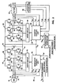
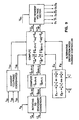
- the power converter for each generator includes an active rectifier, a DC voltage link, an inverter, filters, and associated controls. Both power converters are identical; only one will be explained. More particularly, as illustrated in Figure 2, the active rectifier 20 includes three pairs of active switching devices 60 arranged in a bridge circuit between a +DC rail 68 and a -DC rail 70 of the DC voltage link 24 and each of three stator power taps 72-74 of the generator 16. Each pair of switching devices is coupled between the DC rails 68 and 70, and connected at an intermediate point to one of the stator power taps. Commutation signals that cause the active switching devices to switch on and off originate in a generator control unit 76, which supplies the signals to the switching devices through a drive circuit 78.
- the generator control unit 76 and drive circuit 78 are isolated from the rectifier 20 by optical isolators to minimize interference.
- the commutation signals are complementary for each pair of switching devices, causing one switching device of each pair to switch on and the other switching device of the pair to switch off, as appropriate to achieve the desired stator currents or voltages.
- the switching devices 60 of the rectifier 20 control the stator currents and voltages in the three phase stator windings.
- the switching devices 60 of the rectifier can be any of a number of different types of active switches, including insulated gate bipolar transistors (IGBT), bipolar junction transistors, field effect transistors, Darlington transistors, gate turn-off thyristors, or silicon controlled rectifiers.
- IGBT insulated gate bipolar transistors
- the switching devices 60 of the rectifier are IGBTs, with two IGBTs connected in parallel for each one shown in Figure 2, for a total of twelve devices in the rectifier 20.
- the generator control unit 76 which is part of the generator controller 38, receives sensor inputs of the stator currents i s1 , i s2 , i s3 , and rotor speed ⁇ r , receives a torque reference value T ref from the torque command device 46 ( Figure 1), and generates pulse width modulated (PWM) commutation signals that it supplies to the rectifier switches 60 through the drive circuit 78.
- PWM pulse width modulated
- the DC voltage link 24 consists simply of the two rails 68 and 70, plus an energy storage capacitor 80 connected between the two rails.
- the capacitance of the capacitor 80 is about 15,000 microfarads, and the nominal voltage of the DC link is about 750 volts.
- the inverter 28 also includes three pairs of active switching devices 82 arranged in a bridge circuit between the +DC rail 68 and -DC rail 70 of the DC voltage link 24.
- the intermediate points of the pairs of active switching devices 82 form three output taps 84-86 from which 3-phase electricity flows through the filters 32 and transformer 36 to the utility grid.
- Commutation signals for the active switching devices 82 originate in an inverter control unit 88, which supplies the signals to the switching devices through a drive circuit 90.
- the inverter control unit 88 and drive circuit 90 are isolated from the inverter 28 by optical isolators.
- the commutation signals are complementary for each pair of switching devices, causing one switching device of each pair to switch on and the other switching device of the pair to switch off at any given time.
- the switching devices 82 of the inverter 28 consist of twelve IGBTs arranged in parallel pairs, like the switching devices 60 of the rectifier.
- the inverter control unit 88 which is part of the inverter controller 50, receives sensor inputs of the inverter currents i o1 , i o2 , i o3 , inverter voltages v o1 , v o2 , v o3 , and DC link voltage v dc .
- the inverter currents are sensed at the output taps, while the inverter voltages are sensed at the output of the filters 32 and are isolated through potential transformers 92.
- the inverter control unit 88 also receives, from the power factor controller 54, a power factor signal, a reactive power signal, and an operation mode signal, which define the desired power factor.
- the inverter control unit 88 In response, as will be explained in further detail below, the inverter control unit 88 generates pulse width modulated commutation signals and supplies them to the inverter switches 82 through the drive circuit 90. In addition, the inverter control unit 88 also supplies a feedback signal, Q fb , to the power factor controller 54 that indicates the reactive power being supplied by the inverter 50.
- the control structure of the wind turbine is illustrated in Figure 3 for one of the generators 16.
- the generator control unit 76 includes a field orientation converter 94 that converts the torque reference, T ref , and the rotor speed, ⁇ r , into field oriented control currents, i * / sd and i * / sq, and a rotor flux angle, ⁇ * s .
- These control variables which are identified as control variables by the * superscript, are used by a PWM controller 95 along with the sensed 3-phase stator currents, i s1 , i s2 , i s3 , to generate the PWM commutation signals, D 1 , D 1 , D 2 , D 2 , D 3 , D 3 .
- the notation D n and D n refers to the base drive signals for the upper (D n ) and lower ( D n ) devices of one pair of rectifier switches 60.
- the PWM controller 95 controls stator electrical quantities, either the stator currents or the stator voltages, depending on the rotor monitor 97 monitors the stator currents, generates a signal indicative of actual torque, T fb , and feeds it back to the torque command device 46.
- Controlling the generator currents and voltages in terms of field coordinates is a key element of the present invention.
- the electric torque of an AC induction machine can be expressed in terms of the stator and rotor currents, but such an expression is difficult to use in a torque control system since the rotor currents of a squirrel-cage induction generator cannot be directly measured.
- Field orientation control eliminates that difficulty.
- the rotor flux of an induction machine can be represented by a radial vector ⁇ r with magnitude ⁇ r and angle ⁇ s.
- the field orientation principle defines the stator current in terms of a rotating d,q coordinate system, where a direct (d) axis is aligned with the instantaneous rotor flux vector ⁇ r at angle ⁇ s and a quadrature (q) axis is perpendicular to the rotor flux vector. This is illustrated in Figure 4.
- the stator current vector, i s can be degenerated into a component, i sd , that is parallel to the rotor flux ⁇ r vector and a component i sq , that is perpendicular to the rotor flux vector.
- the currents i sd and i sq at angle ⁇ s, are the field coordinate representation of the stator current vector.
- Figure 4 also illustrates that ⁇ r is defined as the rotor angular speed and ⁇ s is defined as the angular speed of the rotor flux vector.
- the machine slip speed, ⁇ sl which is the speed of the stator current vector with respect to the rotor, is the difference between ⁇ s , and ⁇ r .
- the d,q coordinate system isolates or decouples a current that creates the rotor flux field, i sd , on the direct axis, from a current that creates torque, i sq , on the quadrature axis. Defining the generator currents in field orientation coordinates permits the generator control unit 76 to convert the torque control commands directly into a desired quadrature axis current, i * / sq, which is then used by the PWM controller 95 to carry out the torque commands of the torque command device 46.
- the stator currents in a balanced, 3-phase coordinate system as represented by the currents on the three stator power taps 72-74 ( Figure 2), can be designated by the variables i s1 , i s2 , and i s3 .
- the balanced, 3-phase stator currents are equivalent to 2-phase stator currents, i s ⁇ and i s ⁇ , defined by the following matrix equation:
- the 2-phase stator currents, i s ⁇ , and i s ⁇ can be converted into the field coordinate currents, i sd and i sq , as a function of the rotor flux angle, ⁇ s , by the following transformation: Transformation from field coordinates to 2-phase coordinates is accomplished by inverting equation (2), which results in the following: Transformation from 2-phase to balanced 3-phase coordinates is found by inverting equation (1): Representations of the stator current vector in the rotating d,q field coordinate system, in the stationary 2-phase ⁇ , ⁇ coordinate system, and in the stationary balanced 3-phase coordinate system are shown in Figure 4.
- the structure of the generator control unit 76 is shown in block diagram form in Figure 5.
- the generator control unit is preferably implemented in a digital signal processor ("DSP"), a Texas Instruments model TMS320C25.
- DSP digital signal processor
- TMS320C25 Texas Instruments model
- the generator control unit 76 includes the field orientation converter 94, the torque monitor 97, and the PWM controller 95.
- the PWM controller 95 includes a current controller 96, a voltage controller 98, and a selector circuit 100. These components will be explained in more detail below, but generally, the field orientation converter 94 generates control parameters based on the rotor speed and torque reference signals, the current controller 96 or the voltage controller 98 generates PWM commutation signals for the active switching devices 60, and the selector circuit 100 chooses which of the PWM commutation signals to output to the drive circuit 78.
- the torque monitor 97 senses the actual stator currents, i s1 , i s2 , i s3 , converts them to field coordinate values using equations (1) and (2), and calculates a torque signal, T fb , using equation (8) (see below) for feedback to the torque command device 46.
- the torque monitor 97 thus infers generator torque from the measured currents.
- the computations performed within the DSP of the generator control unit 76 are digital, which requires A/D conversion of the external signals.
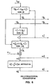
- the field orientation converter 94 converts the torque control and rotor flux signals into field coordinates. Using a desired direct axis current, i * / sd, the field orientation converter 94 computes the desired magnitude of the rotor flux, ⁇ * r .
- the desired flux-producing direct axis current, i * / sd is a function of the particular generator used, and can be predetermined and stored in the DSP. In the preferred embodiment, i * / sd is assumed to be constant. Alternatively, i * / sd can be varied to provide field weakening control, if desired.
- the notation * designates a desired value generated by the control system as opposed to an actual value.
- the computed values for desired field oriented currents, i * / sd and i * / sq, rotor flux, ⁇ * / r, rotor flux speed, ⁇ * / s, and rotor flux angle, ⁇ * / s, are available to the current and voltage controllers 96 and 98 ( Figure 5) for determination of the PWM commutation signals. Transformation of the desired stator currents from field coordinates into stationary 2-phase ⁇ , ⁇ coordinates or balanced 3-phase coordinates, if required by the PWM controller, can be accomplished either in the field orientation converter or in the PWM controller. Here, it is assumed that the transformations occur outside of the field orientation converter 94.
- either the current controller 96 or the voltage controller 98 determines switch states for the active switching devices ( Figure 5).
- the current controller 96 generates PWM commutation signals by choosing a switch state that causes stator currents to approximate the desired currents defined by the field orientation converter.
- the voltage controller 98 generates PWM commutation signals by converting the desired field oriented currents into desired field oriented voltages, transforming them into stator coordinates, and then selecting the appropriate switch state to obtain the desired stator voltages.
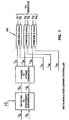
- a delta modulator current controller converts the desired field oriented currents into stationary 2-phase stator coordinates, and then to 3-phase stator coordinates to generate desired 3-phase stator currents, i * / s1, i * / s2,i * / s3.
- the desired stator currents are then transformed into 3-phase coordinates using equation (4).
- the delta modulator current controller After converting the desired stator currents from field coordinates into 3-phase coordinates, the delta modulator current controller then periodically compares each desired stator current i * / s1, i * / s2,i * / s3, with the corresponding actual stator current i s1 , i s2 , i s3 , using compare and hold devices 102. If the desired stator current for a phase is greater than the actual stator current, then the upper switching device is switched on and the lower switching device is switched off, otherwise, the upper device is switched on and the lower device is switched off.
- the compare and hold devices 102 set the PWM commutation signals, D 1 , D 1 , D 2 , D 2 , D 3 , D 3 to accomplish the desired switching.
- the switch state so selected remains in effect until the next sample period occurs, at which time the comparisons are performed with updated actual and desired values.
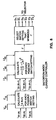
- FIG. 8-10 Another method of current control, one that minimizes a distortion index, is illustrated in Figures 8-10.
- This method generates PWM signals by periodically minimizing a distortion index related directly to total harmonic distortion (THD).
- THD total harmonic distortion
- this method is preferable due to lower THD at comparable frequencies, while requiring fewer switching events and, consequently, less power loss due to switching.
- Minimizing the distortion index, J involves determining which of eight possible switch states of the rectifier switches will produce actual stator currents nearest in value to the desired stator currents.
- One way to accomplish this is shown in Figure 8.
- Switching decisions are made periodically, based on the most recently measured stator currents.
- the distortion index, J can be computed by equations (15) or (16) for each possible switch state.
- the switch state that yields the minimum value of J is output to the selector 100.
- the desired ⁇ and ⁇ axis voltages, v * / s ⁇ and v * / s ⁇ are compared to the limited number of voltage vectors that could result from the eight possible switch states.
- These voltage vectors, shown in Figure 10 have a magnitude of either zero or the DC link voltage, v dc , and are aligned with the s 1 , s 2 , and s 3 axes.
- the voltage vectors are defined according to the following table: State Switch Setting (v s ⁇ , v s ⁇ ) 0 [ D 1 , D 2 , D 3 ] v dc (0, 0) 1 [D 1 , D 2 , D 3 ] v dc (1, 0) 2 [D 1 , D 2 , D 3 ] v dc (1/2, 3 /2) 3 [ D 1 , D 2 , D 3 ] v dc (-1/2, 3 /2) 4 [ D 1 , D 2 , D 3 ] v dc (-1, 0) 5 [ D 1 , D 2 , D 3 ] v dc (-1/2,- 3 /2) 6 [D 1 , D 2 , D 3 ] v dc (1/2,- 3 /2) 7 [D 1 , D 2 , D 3 ] v dc (0,0) Since states 0 and 7 define the same zero voltage, there are seven possible stator voltages
- the ⁇ , ⁇ coordinate space can be divided into seven regions: an inner circle 104 of radius v dc /2, plus six 60° sectors 106-111 of outer radius v dc surrounding the inner circle, each sector having a switch state centered at the outer radius thereof.
- Determining the closest voltage vector is a matter of finding into which region the desired voltage vector falls. To do so, the magnitude of the desired voltage vector is first compared to v dc /2 to determine whether the desired voltage vector falls within the inner circle 104. If the magnitude of the desired voltage vector is less than one-half of v dc , then state O or state 7 is the desired switch state. Choosing between state O and state 7 is accomplished by selecting the state that requires the fewest number of switches to change state from the previous switch setting.
- operation with the current controller 96 generating the PWM commutation signals occurs at relatively low speeds, where the DC voltage link offers substantial ceiling voltage.
- the current controller 96 keeps the stator currents in close agreement with the desired stator current values. This operation effectively results in current sources for the stator windings, which allows the current controller to ignore the stator voltages.
- the voltage controller 98 takes the stator voltages into consideration.
- the selector 100 senses the rotor speed, ⁇ r , and selects the voltage controller 98 instead of the current controller 96 when the rotor speed exceeds a predetermined value.
- This value can be determined empirically by observing the distortion of the current waveform during operation of the current controller at various speeds.
- the switching point is about 1780 rpm.
- some hysteresis is built into the switching point of the selector 100 so that small oscillations of the rotor speed about the switching point do not cause repeated switching between current control and voltage control.
- the DC link voltage and the generator emf can be monitored to determine at which point to switch between current control and voltage control. Monitoring the DC link voltage is not necessary in the preferred embodiment because the inverter control unit 88 maintains that voltage at a fairly constant value.
- the voltage controller 98 periodically generates a set of PWM commutation signals for switching on and off the active switches of the rectifier.
- the voltage controller monitors the desired and actual torque and flux, as defined by the field oriented currents, i * / sd and i * / sq, compensates for the stator voltages, and generates field oriented control voltages, v * / sd and v * / sq, which are used to generate the commutation signals.
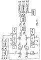
- the operation of the voltage controller 98 is shown in Figure 11.
- the actual 3-phase stator currents, i s1 , i s2 , i s3 are converted into field oriented coordinates by equations (1) and (2).
- the desired voltage on the quadrature axis, v * / sq is generated by first subtracting the actual quadrature current, i sq , from the desired quadrature current, i * / sq, and then running the resultant through a proportional-integral (PI) controller 114 to generate v ' / sq, which is a measure of quadrature axis current error.
- PI proportional-integral
- the value of v ' / sq is then compensated by adding a decoupling factor consisting of the two voltage coupling terms on the right side of equation (29), which results in v * / sqas follows:
- v * sq v ' sq + (1- ⁇ ) L s ⁇ * s ⁇ * r R s L o + ⁇ L s ⁇ * s i sd R s
- the desired voltage on the direct axis is generated by first subtracting the rotor flux divided by the mutual inductance, ⁇ * / r/L o , from the desired direct axis current, i * / sd.
- the resultant is then input to another PI controller 116, which generates v * / sd as a measurement of direct axis current error.
- PI controller 116 is similar to the PI controller 114 for the quadrature component.
- v * sd v ' sd + (1- ⁇ ) L s ⁇ * r R s L o - ⁇ L s ⁇ * s i sq R s
- the desired field coordinate voltages, v * / sd and v * / sq, have been generated, they are transformed into 3-phase stator voltages by equations (3) and (4), resulting in v * / s1, v * / s2, and v * / s3.
- These reference voltages are modulated by a triangular carrier wave to generate the PWM commutation signals, D 1 , D 1 , D 2 , D 2 , D 3 , and D 3 that are sent to the selector 100 ( Figure 5).
- the triangular carrier wave has a frequency of about 8 kHz, while the comparisons between the reference voltages and the carrier wave are performed continuously or at a rate much higher than 8 kHz.
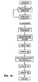
- Figure 12 illustrates how a computer program is structured for execution in the digital signal processor of the generator control unit.
- the program consists primarily of a main loop and an interrupt service routine.
- the main loop initializes the necessary variables, and then loops until it is interrupted, which occurs periodically, at about 8 kHZ in the preferred embodiment.
- the interrupt service routine performs the calculations necessary for generating the PWM commutation signals, and then updates the control variables.
- the interrupt service routine first reads the stator currents, and then executes the code of either the current controller or the voltage controller to generate and output the appropriate switch states.
- the interrupt routine then reads a value for the torque reference, T ref , and updates the corresponding value of the desired quadrature axis current, i * / sq.
- the routine then reads the speed sensor and computes a new value for the rotor speed, ⁇ r .
- the routine updates the value for desired rotor flux, ⁇ * / r, and the desired instantaneous rotor flux angle, ⁇ * / s.
- the interrupt routine then returns to the main loop, which waits until the next periodic interrupt, at which time the updated values will be used to compute the switch states. All constants used in the calculations are computed in advance, and the expressions are arranged to avoid division, which executes relatively slowly in a DSP.
- the steps performed in the computer program can be executed in different order than is shown in Figure 12, but it is important to calculate and output the switch states as soon as possible after reading the actual stator currents.
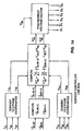
- the inverter control unit 88 is preferably implemented with a digital signal processor, a Texas Instruments model TMS320C25. Computer code for implementing the inverter control function in a DSP is disclosed in the microfiche appendix.
- the inverter control unit controls the inverter switch matrix to supply to the utility grid power with adjustable power factor and low THD.
- the inverter and its control unit can supply or absorb reactive power as needed by adjusting the phase difference between the output voltage and current. Low harmonic distortion is achieved in the same way as in the current controller of the generator control unit, by periodically minimizing a distortion index.
- the inverter control unit also controls the voltage of the DC voltage link, to maintain it at a desired value.
- the inverter control unit uses the output voltage as a sinusoidal waveform reference, rotates the reference waveform by a certain phase angle to generate a rotated reference waveform, or "template”, then multiplies the template waveform by a factor, I ref , derived from the DC link voltage, v dc , to generate a desired current waveform.
- I ref a factor derived from the DC link voltage, v dc
- the actual currents are compared to the desired currents to generate the PWM commutation signals for the inverter switches. All of the calculations of the inverter control unit are performed periodically. In the preferred embodiment, the DSP cycles through its calculations every 125 microseconds, equal to a rate of 8 kHz.
- the multiplication factor, I ref is calculated as follows.
- the measured DC link voltage, v dc is subtracted from a desired value of the DC link voltage, v * / dc, to generate an error, which is then input to a PI controller 130.
- the rotational transformation of the reference waveform can be accomplished in either 3-phase or 2-phase coordinates.
- the template values that result from the rotational transformation, v t ⁇ and v t ⁇ are then multiplied by the value of I ref to generate the desired 2-phase output currents, i * / o ⁇ and i * / o ⁇ .
- the desired output currents are input into a current controller 132, which compares them to the actual currents and generates the appropriate PWM commutation signals for the inverter switches.
- the current controller 132 of the inverter control unit can be implemented in the several ways described above for the current controller 96 of the generator control unit, including the delta modulator. Preferably, however, the current controller 132 generates switch states that minimize the distortion index, J, in a manner similar to that described above with respect to Figures 9 and 10.
- the desired output voltages, v * / o ⁇ and v * / o ⁇ , are then compared to the seven available voltage vectors, and the switch state associated with the nearest voltage vector is selected and output to the inverter switches. Determining the nearest voltage vector is accomplished in the same manner as explained above with respect to the generator current controller of Figures 9 & 10.
- a computer program directs the operation of the digital signal processor of the inverter control unit to perform the calculations described above.
- the computer program is structured like that of the generator control unit in that a main loop executes until periodically interrupted, and then an interrupt service routine updates the sensed inputs, PWM switch state, and calculated variables.
- the interrupt service routine running on the inverter control unit DSP first reads the output currents, output voltages and DC link voltage. Then it calculates the optimal switch state, which it outputs to the inverter switches. Then the interrupt routine performs calculations necessary for the next calculation of switch state by rotating the voltage reference to define the template waveform, computing the multiplication factor I ref , and multiplying the template waveform by I ref to compute the desired currents for the next interrupt. Then control passes to the main loop, where it waits until interrupted again. In the preferred embodiment, interruptions occur at a rate of about 8 kHz.
- the power factor controller 54 can control either the power factor angle, ⁇ , or the magnitude of reactive power to supply VARs (Volt-Ampere-Reactive) to the utility.
- the type of power factor control is specified by the operation mode signal that is input into the power factor controller. If the power factor angle is controlled, the power factor controller 54 outputs to the inverter control unit 88 a constant value of ⁇ that is defined by the power factor input signal. If the reactive power is controlled, the power factor controller monitors the reactive power feedback signal, Q fb , compares it to a desired reactive power level defined by the reactive power input signal, and adjusts the power factor angle, ⁇ , to obtain the desired reactive power.
- the power factor correction facility of the inverter control unit can be utilized even when the wind turbine is not operating, by operating in a static VAR mode. To do so, the power factor controller 54 sets the power factor angle ⁇ equal to 90°. After the DC link is charged up by the utility through the inverter, the inverter control unit operates as described above to rotate the output current to lead the voltage by 90°. This supplies reactive power to the utility to counteract reactive loads drawing power from the utility grid.
- the invention disclosed herein provides a novel and advantageous variable speed wind turbine.
- the foregoing discussion discloses and describes merely exemplary methods and embodiments of the present invention.
- the invention may be embodied in other specific forms without departing from essential characteristics thereof.
- some aspects of the current controller can be performed in various ways equivalent to those disclosed herein, including using hysteresis control or forced oscillation with triangular intersection.
- the generator need not be a 3-phase squirrel-cage induction generator, but may be any multiphase generator, including a synchronous generator. Certain aspects of the generator control could be performed open-loop, instead of the closed loop control disclosed herein.
- the power converter could have a DC current link, or could be a cyclo-converter instead of a DC voltage link.
- the torque monitor could directly measure torque with a transducer, instead of inferring torque from the measured stator currents. Accordingly, the disclosure of the present invention is intended to be illustrative, but not limiting, of the scope of the invention, which is set forth in the following claims.
Description
- This invention relates generally to wind turbines that operate at variable speed under varying wind conditions, and relates more particularly to a power converter for converting wind energy into AC electrical power at a controlled power factor and for controlling the torque generated by the wind turbine.
- Wind turbines provide a primary source of energy that can be converted into electricity and supplied to utility power grids. Conversion of wind energy to electrical energy is accomplished in a wind turbine by driving an electrical generator, commonly an AC induction generator. If the electrical power generated by a wind turbine is to be supplied to a utility power grid, then it is required to have a constant frequency, e.g., 60 Hertz, that is synchronized to the utility line frequency. This can be accomplished by driving the generator at a constant rotational speed, which, unless a variable speed transmission is used, requires that the wind turbine rotate at a constant speed. Unfortunately, constant speed operation of a wind turbine limits its energy conversion efficiency due to variable wind conditions. Turbine rotor speed needs to be proportional to wind speed for optimal energy recovery.
- Variable speed wind turbines have been proposed as a way of increasing the energy conversion efficiencies of constant speed wind turbines. By varying the rotor speed in varying wind conditions, improved energy recovery can be achieved over a range of wind speed. Also importantly, the peak mechanical stresses caused by wind gusts can be reduced by limiting the torque reacted on the wind turbine by the generator and allowing the wind turbine to speed up in response to wind gusts. The increased kinetic energy of the rotor caused by wind gusts serves as a short term energy storage medium to further improve energy conversion. Such operation, however, requires a responsive torque control system.
- Although variable speed wind turbines are advantageous from the perspective of increased energy conversion and reduced stresses, the electrical generation system is more complicated than that of a constant speed wind turbine. Since a generator is usually coupled to a variable speed rotor through a fixed-ratio gear transmission, the electrical power produced by the generator will have a variable frequency. This requires a conversion from the variable frequency AC output by the generator to a constant frequency AC for supplying the utility power grid. The conversion can be accomplished either directly by a frequency converter or through an intermediate conversion to DC by a rectifier and reconversion to fixed-frequency AC by an inverter.
- An example of a prior art variable speed wind turbine is disclosed in US-A-4700081 (Kos et al) which includes speed avoidance logic to prevent the turbine lingering at a critical speed which would tend to cause excessive vibration. Such also discloses the use of a frequence converter for converting the variable frequency AC produced by the wind turbine to a fixed frequence AC for supply to the power grid. Further, PESC'86, 17th Annual IEEE Power Electronics Specialist Conference, pages 94 to 501, an article by BE.T.OOI et al, discloses "An integrated AC drive system using a controlled-current PWM rectifier/inverter link".
- Document D1 (DE 37 27 696) discloses a method and an apparatus for an asynchronous run-up of an asynchronous generator that can be used in wind turbines. Document D1 deals with the problem that additional equipment is usually required, in order to accelerate the rotor of the generator from a complete stop/low speed to its operational speed. The teaching of document D1 tries to avoid this additional equipment and provides a method/apparatus for a run-up of the generator which basically uses only the equipment required during the "normal" operation of the generator.
- As can be seen from document D1, the method/apparatus according to document D1 is based on an arrangement wherein the rotor windings of a generator G are connected to a converter DU and the stator windings of the generator G are connected to a grid N.
- Thereby, the method according to document D1 comprises steps that: a) the stator windings are disconnected from the grid and either short-circuited or connected to the rotor windings (including a reversal of the phase sequence); b) the field angle is calculated; and c) based on a predetermined field-oriented rotor set vector (iL(F)) control signals (iL(L)*, uL(L)*) for the converter DU are formed. During the run-up of the generator, the generator is operated as a motor.
- Document D2 (EP-A-0 244 341) discloses a method for controlling a wind turbine which avoids the turbine lingering at a critical speed which would otherwise tend to cause excessive vibration. The teaching according to document D2 is based on the fact that the kinetic energy available from an oncoming wind stream varies on the size of swept area, density, and cube of the wind velocity. It has been shown that no more than 59% of the energy can be extracted and the ability of any wind turbine to approach that maximum has been named the coefficient of performance, Cp. The coefficient Cp is related to the aerodynamic features of a given machine, particularly the tip speed ratio, which is defined as the ratio of tangential speed of the blade tip over the speed of the oncoming wind. If this ratio can be maintained at the machine's peak coefficient of performance by letting rotor speed follow wind speed, the wind turbine becomes highly efficient.
- In order to keep the velocity ratio at the point at which the coefficient of performance is maximized, document D2 discloses the design of a variable speed wind turbine.
- Thereby, an AC generator has a generator rotor shaft attached to a high speed side of the gearbox. The turbine rotor torque QS drives the generator rotor through the gearbox. The generator provides an air gap torque QE which opposes the geared input turbine rotor torque. The AC generator provides variable frequency AC on a line to a frequency converter which converts the variable frequency AC to a fixed frequency AC on a line which is in turn provided to a power grid. A variable speed wind turbine controller is shown responsive to sensed speed and power signals and also providing a command torque signal on the line to the frequency converter. The variable speed wind turbine controller comprises a schedule including a functional relationship between sensed power signal values and corresponding generator speed reference (command) signal values. Based on this information the variable speed wind turbine controller in effect determines what the generator air gap torque should be to obtain maximum efficiency. In addition, a rotor control may be provided to provide aerodynamic torque control above a limiting torque in order to limit thrust. This may take the form of blade pitch or turbine yaw control.
- Following this strategy of variable speed operation, there will, however, be certain speeds within the operation range at which system resonances will occur. Therefore, document D2 provides a method for avoiding a critical speed which may cause undesirable vibrations in the wind turbine. The method according to document D2 takes into account the desirability of maintaining the maximum efficiency speed rate of increase line, while at the same time avoiding that rate of increase where it could result in command speeds corresponding to the critical speed.
- None of documents D1 and D2 discloses, individually or in combination, the use of a torque command means to define a torque reference signal used by a generator control means to control the active switches of a variable speed wind turbine power converter via a field orientation means that defines a desired current in field coordinates and a switch control means to control the active switches.
- The invention is defined by the features of the independent claims. Preferred embodiments are defined in the dependent claims.
-
- Figure 1 is a block diagram of a wind turbine.
- Figure 2 is a schematic diagram of a power converter circuit and block diagram of associated control circuits.
- Figure 3 is a block diagram of the control system used to control generator torque.
- Figure 4 is a graphical diagram illustrating the angular relationships between a fixed stator coordinate system, a rotating rotor coordinate system, and a rotating field oriented coordinate system.
- Figure 5 is a block diagram of a generator control unit.
- Figure 6 is a block diagram of a field orientation converter.
- Figure 7 is a block diagram of a delta modulator current controller.
- Figure 8 is a block diagram of a distortion index current controller.
- Figure 9 is a block diagram of an alternative implementation of the distortion index current controller of Figure 8.
- Figure 10 is a graphical representation, in α,β coordinates, of voltage vectors resulting from eight possible switch states of the active rectifier.
- Figure 11 is a block diagram of a voltage controller.
- Figure 12 is a block diagram of a computer program used in the generator control unit.
- Figure 13 is a block diagram of an inverter control unit of the present invention.
- Figure 14 is a block diagram of a current controller used in the inverter control unit of Figure 13.
- Figure 15 is a block diagram of a computer program used in the inverter control unit of the present invention.
-
- Figures 1 through 15 of the drawings disclose various embodiments of the present invention for purposes of illustration only. One skilled in the art will readily recognize from the following discussion that alternative embodiments of the structures and methods illustrated herein may be employed without departing from the principles of the invention as claimed.
- The preferred embodiment of the present invention is a variable speed wind turbine with a power converter that supplies constant frequency, high quality power at an adjustable power factor to a utility grid. As shown in Figure 1, the wind turbine 10 includes a variable pitch turbine rotor 12 that is mechanically coupled through a gear box 14 to two 3-phase AC induction generators 16 and 18. The gear box 14 includes a fixed-ratio, step-up transmission, so that the generator rotors rotate at a fixed multiple of the speed of the turbine rotor. The generators 16 and 18 produce 3-phase AC electricity at a variable frequency that is proportional to the speed of the turbine rotor. The electricity generated by each generator 16 and 18 is converted from variable frequency AC to fixed frequency AC by power converters that comprise active rectifiers 20 and 22, DC voltage links 24 and 26, inverters 28 and 30, and filters 32 and 34. The outputs of the filters 32 and 34 are combined at a transformer 36, the output of which is supplied to the utility grid.
- The two generators, both of which rotate at all times whenever the turbine rotor rotates, are preferred over one generator in this embodiment in crder to build a high capacity wind turbine while using readily available generators. The invention can, of course, be implemented in a wind turbine with only one generator or more than two generators.
- Each of the generators 16 and 18 is controlled separately by generator controllers 38 and 40, which, as explained below, control the torque reacted by the generators by controlling the stator currents or voltages. Shaft speed sensors 42 and 44 monitor the rotor speed of the two generators, respectively, and supply rotor speed information to the generator controllers 38 and 40 and to a torque command device 46. The inverters 28 and 30 are controlled separately by inverter controllers 50 and 52. A power factor controller 54 directs the inverter controllers 50 and 52 to provide power factor correction by shifting the output current with respect to the output voltage.
- The torque command device 46 monitors wind turbine performance parameters and generates torque control signals to the generator controllers 38 and 40 and pitch angle control signals to a pitch control unit 48. Stored within the torque command device 46 is a table of optimal values of torque, pitch angle, and rotor speed for various operating conditions. These values are given as a function of an estimated wind speed, which is determined by an aerodynamic model of the wind turbine having inputs of rotor speed from the speed sensors 42 and 44, measured pitch angle from the pitch control unit 48, and measured torque from the generator controllers 38 and 40. In order to improve the dynamic stability of the overall control system, a speed control signal is used to adjust the optimal values of pitch angle and torque found from the table. The speed control signal is proportional to the difference between the optimal desired speed from the table and the measured speed from the speed sensors 42 and 44. The torque command device 46 thus determines desired values of torque and pitch angle based on the sensed operating conditions and supplies torque and pitch angle control signals to the generator controllers 38, 40 and pitch control unit 48, respectively.
- Broadly speaking, the power converter for each generator includes an active rectifier, a DC voltage link, an inverter, filters, and associated controls. Both power converters are identical; only one will be explained. More particularly, as illustrated in Figure 2, the active rectifier 20 includes three pairs of active switching devices 60 arranged in a bridge circuit between a +DC rail 68 and a -DC rail 70 of the DC voltage link 24 and each of three stator power taps 72-74 of the generator 16. Each pair of switching devices is coupled between the DC rails 68 and 70, and connected at an intermediate point to one of the stator power taps. Commutation signals that cause the active switching devices to switch on and off originate in a generator control unit 76, which supplies the signals to the switching devices through a drive circuit 78. The generator control unit 76 and drive circuit 78 are isolated from the rectifier 20 by optical isolators to minimize interference. The commutation signals are complementary for each pair of switching devices, causing one switching device of each pair to switch on and the other switching device of the pair to switch off, as appropriate to achieve the desired stator currents or voltages. The switching devices 60 of the rectifier 20 control the stator currents and voltages in the three phase stator windings.
- The switching devices 60 of the rectifier can be any of a number of different types of active switches, including insulated gate bipolar transistors (IGBT), bipolar junction transistors, field effect transistors, Darlington transistors, gate turn-off thyristors, or silicon controlled rectifiers. In the preferred embodiment, the switching devices 60 of the rectifier are IGBTs, with two IGBTs connected in parallel for each one shown in Figure 2, for a total of twelve devices in the rectifier 20.
- The generator control unit 76, which is part of the generator controller 38, receives sensor inputs of the stator currents is1, is2, is3, and rotor speed ωr, receives a torque reference value Tref from the torque command device 46 (Figure 1), and generates pulse width modulated (PWM) commutation signals that it supplies to the rectifier switches 60 through the drive circuit 78. Although Figure 2 shows sensing of all three stator currents, only two currents need to be sensed because the third can be found from the relationship is1 + is2 + is3 = 0. The operation of the generator control unit 76 will be explained in further detail below.
- The DC voltage link 24 consists simply of the two rails 68 and 70, plus an energy storage capacitor 80 connected between the two rails. In the preferred embodiment, where each generator is rated at 150 kilowatts, the capacitance of the capacitor 80 is about 15,000 microfarads, and the nominal voltage of the DC link is about 750 volts.
- Situated on the other side of the DC voltage link from the active rectifier 20, the inverter 28 also includes three pairs of active switching devices 82 arranged in a bridge circuit between the +DC rail 68 and -DC rail 70 of the DC voltage link 24. The intermediate points of the pairs of active switching devices 82 form three output taps 84-86 from which 3-phase electricity flows through the filters 32 and transformer 36 to the utility grid. Commutation signals for the active switching devices 82 originate in an inverter control unit 88, which supplies the signals to the switching devices through a drive circuit 90. The inverter control unit 88 and drive circuit 90 are isolated from the inverter 28 by optical isolators. The commutation signals are complementary for each pair of switching devices, causing one switching device of each pair to switch on and the other switching device of the pair to switch off at any given time. In the preferred embodiment, the switching devices 82 of the inverter 28 consist of twelve IGBTs arranged in parallel pairs, like the switching devices 60 of the rectifier.
- The inverter control unit 88, which is part of the inverter controller 50, receives sensor inputs of the inverter currents io1, io2, io3, inverter voltages vo1, vo2, vo3, and DC link voltage vdc. The inverter currents are sensed at the output taps, while the inverter voltages are sensed at the output of the filters 32 and are isolated through potential transformers 92. The inverter control unit 88 also receives, from the power factor controller 54, a power factor signal, a reactive power signal, and an operation mode signal, which define the desired power factor. In response, as will be explained in further detail below, the inverter control unit 88 generates pulse width modulated commutation signals and supplies them to the inverter switches 82 through the drive circuit 90. In addition, the inverter control unit 88 also supplies a feedback signal, Qfb, to the power factor controller 54 that indicates the reactive power being supplied by the inverter 50.
- The control structure of the wind turbine is illustrated in Figure 3 for one of the generators 16. The generator control unit 76 includes a field orientation converter 94 that converts the torque reference, Tref, and the rotor speed, ωr, into field oriented control currents, i * / sd and i * / sq, and a rotor flux angle, *s. These control variables, which are identified as control variables by the * superscript, are used by a PWM controller 95 along with the sensed 3-phase stator currents, is1, is2, is3, to generate the PWM commutation signals, D1,
D 1, D2,D 2, D3,D 3. The notation Dn andD n for example, refers to the base drive signals for the upper (Dn) and lower (D n) devices of one pair of rectifier switches 60. The PWM controller 95, as will be described in more detail below, controls stator electrical quantities, either the stator currents or the stator voltages, depending on the rotor monitor 97 monitors the stator currents, generates a signal indicative of actual torque, Tfb, and feeds it back to the torque command device 46. - Controlling the generator currents and voltages in terms of field coordinates is a key element of the present invention. The electric torque of an AC induction machine can be expressed in terms of the stator and rotor currents, but such an expression is difficult to use in a torque control system since the rotor currents of a squirrel-cage induction generator cannot be directly measured. Field orientation control eliminates that difficulty.
- It is important to understand that, at any instant of time, the rotor flux of an induction machine can be represented by a radial vector λr with magnitude λr and angle s. The field orientation principle defines the stator current in terms of a rotating d,q coordinate system, where a direct (d) axis is aligned with the instantaneous rotor flux vector λr at angle s and a quadrature (q) axis is perpendicular to the rotor flux vector. This is illustrated in Figure 4. The stator current vector, i s, can be degenerated into a component, isd, that is parallel to the rotor flux λ r vector and a component isq, that is perpendicular to the rotor flux vector. The currents isd and isq at angle s, are the field coordinate representation of the stator current vector.
- Figure 4 also illustrates that ωr is defined as the rotor angular speed and ωs is defined as the angular speed of the rotor flux vector. The machine slip speed, ωsl, which is the speed of the stator current vector with respect to the rotor, is the difference between ωs, and ωr.
- The d,q coordinate system isolates or decouples a current that creates the rotor flux field, isd, on the direct axis, from a current that creates torque, isq, on the quadrature axis. Defining the generator currents in field orientation coordinates permits the generator control unit 76 to convert the torque control commands directly into a desired quadrature axis current, i * / sq, which is then used by the PWM controller 95 to carry out the torque commands of the torque command device 46.
- Controlling the generator in this manner requires conversion between stationary stator coordinates and rotating field coordinates. The stator currents in a balanced, 3-phase coordinate system, as represented by the currents on the three stator power taps 72-74 (Figure 2), can be designated by the variables is1, is2, and is3. The balanced, 3-phase stator currents are equivalent to 2-phase stator currents, isα and isβ, defined by the following matrix equation:

- The 2-phase stator currents, isα, and isβ, can be converted into the field coordinate currents, isd and isq, as a function of the rotor flux angle, s, by the following transformation:Transformation from field coordinates to 2-phase coordinates is accomplished by inverting equation (2), which results in the following:
 Transformation from 2-phase to balanced 3-phase coordinates is found by inverting equation (1):
 Representations of the stator current vector in the rotating d,q field coordinate system, in the stationary 2-phase α,β coordinate system, and in the stationary balanced 3-phase coordinate system are shown in Figure 4.
- The structure of the generator control unit 76 is shown in block diagram form in Figure 5. The generator control unit is preferably implemented in a digital signal processor ("DSP"), a Texas Instruments model TMS320C25. Computer code for implementing the invention in a DSP is disclosed in the microfiche appendix.
- Functionally, the generator control unit 76 includes the field orientation converter 94, the torque monitor 97, and the PWM controller 95. In the preferred embodiment, the PWM controller 95 includes a current controller 96, a voltage controller 98, and a selector circuit 100. These components will be explained in more detail below, but generally, the field orientation converter 94 generates control parameters based on the rotor speed and torque reference signals, the current controller 96 or the voltage controller 98 generates PWM commutation signals for the active switching devices 60, and the selector circuit 100 chooses which of the PWM commutation signals to output to the drive circuit 78. The torque monitor 97 senses the actual stator currents, is1, is2, is3, converts them to field coordinate values using equations (1) and (2), and calculates a torque signal, Tfb, using equation (8) (see below) for feedback to the torque command device 46. The torque monitor 97 thus infers generator torque from the measured currents. The computations performed within the DSP of the generator control unit 76 are digital, which requires A/D conversion of the external signals.
- The field orientation converter 94, illustrated in Figure 6, converts the torque control and rotor flux signals into field coordinates. Using a desired direct axis current, i * / sd, the field orientation converter 94 computes the desired magnitude of the rotor flux, λ*r. The desired flux-producing direct axis current, i * / sd, is a function of the particular generator used, and can be predetermined and stored in the DSP. In the preferred embodiment, i * / sd is assumed to be constant. Alternatively, i * / sd can be varied to provide field weakening control, if desired. The notation * designates a desired value generated by the control system as opposed to an actual value.
- The desired rotor flux, λ * / r, is defined by the following equation:
- λ * / r =
- desired rotor flux;
- λ ˙ * / r =
- time derivative of desired rotor flux;
- Rr =
- rotor resistance;
- Lo =
- mutual inductance;
- Lr =
- rotor self inductance.
- λ * / r(k) =
- λ * / r at time = k;
- λ * / r(k-1) =
- λ * / r at time = k-1;
- i * / sd(k-1) =
- i * / sd at time = k-1;
- Δt =
- sample time period between time = k-1 and time = k.
- T =
- generator torque;
- P =
- number of generator poles;
- isq =
- quadrature axis current.
- Once the desired rotor flux, λ * / r, and desired quadrature axis current, i * / sq, have been determined, the desired rotor flux angle, * / s, at a particular instant of time can be found. This is accomplished by solving the following equations:
- ω * / s1 =
- desired machine slip speed;
- ω * / s =
- desired rotor flux speed;
- ωr =
- actual rotor speed;
- * / s =
- desired instantaneous rotor flux angle.
- The computed values for desired field oriented currents, i * / sd and i * / sq, rotor flux, λ * / r, rotor flux speed, ω * / s, and rotor flux angle, * / s, are available to the current and voltage controllers 96 and 98 (Figure 5) for determination of the PWM commutation signals. Transformation of the desired stator currents from field coordinates into stationary 2-phase α,β coordinates or balanced 3-phase coordinates, if required by the PWM controller, can be accomplished either in the field orientation converter or in the PWM controller. Here, it is assumed that the transformations occur outside of the field orientation converter 94.
- In response to the values computed by the field orientation converter 94, either the current controller 96 or the voltage controller 98, depending on which is selected, determines switch states for the active switching devices (Figure 5). The current controller 96 generates PWM commutation signals by choosing a switch state that causes stator currents to approximate the desired currents defined by the field orientation converter. The voltage controller 98 generates PWM commutation signals by converting the desired field oriented currents into desired field oriented voltages, transforming them into stator coordinates, and then selecting the appropriate switch state to obtain the desired stator voltages.
- One simple method of current control is illustrated in Figure 7, a delta modulator current controller. The delta modulator current controller converts the desired field oriented currents into stationary 2-phase stator coordinates, and then to 3-phase stator coordinates to generate desired 3-phase stator currents, i * / s1, i * / s2,i * / s3.
- Transforming the desired currents from rotating field coordinates to stationary 2-phase α,β coordinates is achieved by equation (3), which reduces to the following:
- After converting the desired stator currents from field coordinates into 3-phase coordinates, the delta modulator current controller then periodically compares each desired stator current i * / s1, i * / s2,i * / s3, with the corresponding actual stator current is1, is2, is3, using compare and hold devices 102. If the desired stator current for a phase is greater than the actual stator current, then the upper switching device is switched on and the lower switching device is switched off, otherwise, the upper device is switched on and the lower device is switched off. The compare and hold devices 102 set the PWM commutation signals, D1,
D 1, D2,D 2, D3,D 3 to accomplish the desired switching. The switch state so selected remains in effect until the next sample period occurs, at which time the comparisons are performed with updated actual and desired values. - Another method of current control, one that minimizes a distortion index, is illustrated in Figures 8-10. This method generates PWM signals by periodically minimizing a distortion index related directly to total harmonic distortion (THD). In comparison with the delta modulator current controller or with a linear controller with triangular crossing, this method is preferable due to lower THD at comparable frequencies, while requiring fewer switching events and, consequently, less power loss due to switching. The distortion index that is minimized may be defined as the sum of the squares of the current errors:
- Minimizing the distortion index, J, involves determining which of eight possible switch states of the rectifier switches will produce actual stator currents nearest in value to the desired stator currents. One way to accomplish this is shown in Figure 8. Switching decisions are made periodically, based on the most recently measured stator currents. The actual stator currents is1(k), is2(k), and is3(k), are measured at time = k, and a projection is made of the stator currents is1(k+1), is2(k+1), and is3(k+1) at the next interval of time, for each possible switch state. Since there are two possible switch settings for each of the three switch pairs, there are eight (23) possible switch states for the rectifier switches. The projected stator currents is1(k+1), is2(k+1), and is3(k+1) are found by modeling the generator and rectifier according to the following equation derived from a simplified model:
- V =
- voltage vector resulting from a particular switch state;
- E =
- generator emf vector;
- i s =
- stator current vector.
- After the projected stator currents are found, the distortion index, J, can be computed by equations (15) or (16) for each possible switch state. The switch state that yields the minimum value of J is output to the selector 100.
- While the above-described method will define a switch state that minimizes the distortion index, another equivalent method is preferable due to its reduced computational overhead The alternative method of computing the switch state that minimizes the distortion index is illustrated in Figures 9 and 10. This method converts the desired stator current vector into an equivalent desired voltage vector, and then finds the switch state that would most closely approximate the desired voltage vector. This method in effect minimizes an equivalent distortion index defined in the α,β coordinate system with respect to voltage error:
- v * / sα =
- desired α axis voltage;
- v * / sβ =
- desired β axis voltage;
- vsα =
- actual α axis voltage;
- vsβ =
- actual β axis voltage.
- As shown in Figure 9, computations are carried out using the 2-phase α,β coordinate system instead of the 3-phase coordinate system in order to eliminate some redundant computational steps. The measured 3-phase stator currents, is1, is2, and is3, are converted into the 2-phase α,β coordinate system using equation (1). The desired field coordinate currents, i * / sd and i * / sq, as received from the field orientation converter 94 (Figure 5), are converted into desired α,β stator currents at time (k), i * / sα(k) and i * / sβ(k), using equation (3). These values are projected forward in time using the formulas:
- Next, instead of solving equation (19) or (20) for each possible switch state, the desired α and β axis voltages, v * / sα and v * / sβ, are compared to the limited number of voltage vectors that could result from the eight possible switch states. These voltage vectors, shown in Figure 10, have a magnitude of either zero or the DC link voltage, vdc, and are aligned with the s1, s2, and s3 axes. The voltage vectors are defined according to the following table:
State Switch Setting (vsα, vsβ) 0 [ D 1,D 2,D 3]vdc (0, 0) 1 [D1, D 2,D 3]vdc (1, 0) 2 [D1, D2, D 3]vdc (1/2, 3 [ D 1, D2,D 3]vdc (-1/2, 4 [ D 1, D2, D3]vdc (-1, 0) 5 [ D 1,D 2, D3]vdc (-1/2,- 6 [D1, D 2, D3]vdc (1/2,- 7 [D1, D2, D3] vdc (0,0) - Minimizing the distortion index is accomplished by finding which stator voltage vector is closest to the desired voltage vector defined by v * / sα and v * / sβ. Graphically, the α,β coordinate space can be divided into seven regions: an inner circle 104 of radius vdc/2, plus six 60° sectors 106-111 of outer radius vdc surrounding the inner circle, each sector having a switch state centered at the outer radius thereof.
- Determining the closest voltage vector is a matter of finding into which region the desired voltage vector falls. To do so, the magnitude of the desired voltage vector is first compared to vdc/2 to determine whether the desired voltage vector falls within the inner circle 104. If the magnitude of the desired voltage vector is less than one-half of vdc, then state O or state 7 is the desired switch state. Choosing between state O and state 7 is accomplished by selecting the state that requires the fewest number of switches to change state from the previous switch setting.
- Next, if the magnitude of the desired voltage vector exceeds vdc/2, then the signs of v * / sα and v * / sβ are examined to determine in which quadrant the voltage vector falls. If the sign of v * / sα is positive, then states 1, 2, or 6 are candidates, and, if negative, then states 3, 4, or 5 are candidates. If both v * / sα and v * / sβ are positive, for example, then either state 1 or state 2 is the closest voltage vector. For v * / sα and v * / sβ positive, state 1 is closest if v * / sα >
- The selections between states 3 and 4, 4 and 5, and 1 and 6 in the other quadrants are developed in the same manner. Once the closest voltage vector is found, the switch state associated with that voltage vector is output to the selector 100.
- Referring back to Figure 5, operation with the current controller 96 generating the PWM commutation signals occurs at relatively low speeds, where the DC voltage link offers substantial ceiling voltage. In that situation, the current controller 96 keeps the stator currents in close agreement with the desired stator current values. This operation effectively results in current sources for the stator windings, which allows the current controller to ignore the stator voltages.
- At higher speeds, however, where the generator emf approaches the voltage of the DC voltage link, the stator voltages can no longer be ignored. In this operating region, the voltage controller 98 takes the stator voltages into consideration.
- The selector 100 senses the rotor speed, ωr, and selects the voltage controller 98 instead of the current controller 96 when the rotor speed exceeds a predetermined value. This value can be determined empirically by observing the distortion of the current waveform during operation of the current controller at various speeds. In the preferred embodiment, using a four pole squirrel-cage induction generator with a 1800 rpm synchronous speed and operating at a nominal voltage of 750 volts, the switching point is about 1780 rpm. Preferably, some hysteresis is built into the switching point of the selector 100 so that small oscillations of the rotor speed about the switching point do not cause repeated switching between current control and voltage control. As an alternative to or in addition to monitoring the rotor speed, the DC link voltage and the generator emf can be monitored to determine at which point to switch between current control and voltage control. Monitoring the DC link voltage is not necessary in the preferred embodiment because the inverter control unit 88 maintains that voltage at a fairly constant value.
- Like the current controller 96, the voltage controller 98 periodically generates a set of PWM commutation signals for switching on and off the active switches of the rectifier. The voltage controller monitors the desired and actual torque and flux, as defined by the field oriented currents, i * / sd and i * / sq, compensates for the stator voltages, and generates field oriented control voltages, v * / sd and v * / sq, which are used to generate the commutation signals.
- The stator voltages, in field coordinates, are defined by the following equations:
- σ =
- total or global leakage factor;
- Ls =
- stator inductance;
- Rs =
- stator resistance.
- The operation of the voltage controller 98 is shown in Figure 11. The actual 3-phase stator currents, is1, is2, is3, are converted into field oriented coordinates by equations (1) and (2). The desired voltage on the quadrature axis, v * / sq, is generated by first subtracting the actual quadrature current, isq, from the desired quadrature current, i * / sq, and then running the resultant through a proportional-integral (PI) controller 114 to generate v ' / sq, which is a measure of quadrature axis current error. The PI controller supplies a proportional/integral output of the form:
- Similarly, the desired voltage on the direct axis, v * / sd, is generated by first subtracting the rotor flux divided by the mutual inductance, λ * / r/Lo, from the desired direct axis current, i * / sd. The resultant is then input to another PI controller 116, which generates v * / sd as a measurement of direct axis current error. PI controller 116 is similar to the PI controller 114 for the quadrature component. The value of v ' / sd is then compensated by adding a decoupling factor consisting of the two voltage coupling terms on the right side of equation (28), which results in v * / sd as follows:
- Once the desired field coordinate voltages, v * / sd and v * / sq, have been generated, they are transformed into 3-phase stator voltages by equations (3) and (4), resulting in v * / s1, v * / s2, and v * / s3. These reference voltages are modulated by a triangular carrier wave to generate the PWM commutation signals, D1,
D 1, D2,D 2, D3, andD 3 that are sent to the selector 100 (Figure 5). In the preferred embodiment, the triangular carrier wave has a frequency of about 8 kHz, while the comparisons between the reference voltages and the carrier wave are performed continuously or at a rate much higher than 8 kHz. - Figure 12 illustrates how a computer program is structured for execution in the digital signal processor of the generator control unit. The program consists primarily of a main loop and an interrupt service routine. The main loop initializes the necessary variables, and then loops until it is interrupted, which occurs periodically, at about 8 kHZ in the preferred embodiment. The interrupt service routine performs the calculations necessary for generating the PWM commutation signals, and then updates the control variables. Upon interrupt, the interrupt service routine first reads the stator currents, and then executes the code of either the current controller or the voltage controller to generate and output the appropriate switch states. The interrupt routine then reads a value for the torque reference, Tref, and updates the corresponding value of the desired quadrature axis current, i * / sq. The routine then reads the speed sensor and computes a new value for the rotor speed, ωr. The routine updates the value for desired rotor flux, λ * / r, and the desired instantaneous rotor flux angle, * / s. The interrupt routine then returns to the main loop, which waits until the next periodic interrupt, at which time the updated values will be used to compute the switch states. All constants used in the calculations are computed in advance, and the expressions are arranged to avoid division, which executes relatively slowly in a DSP. The steps performed in the computer program can be executed in different order than is shown in Figure 12, but it is important to calculate and output the switch states as soon as possible after reading the actual stator currents.
- Turning now to the inverter side of the wind turbine system, the details of the inverter control unit 88 are shown in Figures 13-15. Like the generator control unit 76, the inverter control unit is preferably implemented with a digital signal processor, a Texas Instruments model TMS320C25. Computer code for implementing the inverter control function in a DSP is disclosed in the microfiche appendix.
- The inverter control unit controls the inverter switch matrix to supply to the utility grid power with adjustable power factor and low THD. The inverter and its control unit can supply or absorb reactive power as needed by adjusting the phase difference between the output voltage and current. Low harmonic distortion is achieved in the same way as in the current controller of the generator control unit, by periodically minimizing a distortion index. In addition, the inverter control unit also controls the voltage of the DC voltage link, to maintain it at a desired value.
- As shown in Figure 13, the inverter control unit uses the output voltage as a sinusoidal waveform reference, rotates the reference waveform by a certain phase angle to generate a rotated reference waveform, or "template", then multiplies the template waveform by a factor, Iref, derived from the DC link voltage, vdc, to generate a desired current waveform. The actual currents are compared to the desired currents to generate the PWM commutation signals for the inverter switches. All of the calculations of the inverter control unit are performed periodically. In the preferred embodiment, the DSP cycles through its calculations every 125 microseconds, equal to a rate of 8 kHz.
- The multiplication factor, Iref, is calculated as follows. The measured DC link voltage, vdc, is subtracted from a desired value of the DC link voltage, v * / dc, to generate an error, which is then input to a PI controller 130. The PI controller supplies a proportional/integral output of the form:
- The rotational transformation of the reference waveform can be accomplished in either 3-phase or 2-phase coordinates. In 3-phase coordinates, the template waveform, rotated by an angle , is calculated as follows:


- The current controller 132 of the inverter control unit can be implemented in the several ways described above for the current controller 96 of the generator control unit, including the delta modulator. Preferably, however, the current controller 132 generates switch states that minimize the distortion index, J, in a manner similar to that described above with respect to Figures 9 and 10. Referring to Figure 14, the inverter current controller generates desired output voltages, v * / oα and v * / oβ, according to the following equations:
i * / oα(k+1) and i * / oβ(k+1) are the desired output currents at time = k+1 in α,β coordinates;
ioα and ioβ are the measured output currents in α,β coordinates;
voα and voβ are the measured output voltages in α,β coordinates; and
Δt is the sample period. - The desired output voltages, v * / oα and v * / oβ, are then compared to the seven available voltage vectors, and the switch state associated with the nearest voltage vector is selected and output to the inverter switches. Determining the nearest voltage vector is accomplished in the same manner as explained above with respect to the generator current controller of Figures 9 & 10.
- A computer program directs the operation of the digital signal processor of the inverter control unit to perform the calculations described above. As shown in Figure 15, the computer program is structured like that of the generator control unit in that a main loop executes until periodically interrupted, and then an interrupt service routine updates the sensed inputs, PWM switch state, and calculated variables. The interrupt service routine running on the inverter control unit DSP first reads the output currents, output voltages and DC link voltage. Then it calculates the optimal switch state, which it outputs to the inverter switches. Then the interrupt routine performs calculations necessary for the next calculation of switch state by rotating the voltage reference to define the template waveform, computing the multiplication factor Iref, and multiplying the template waveform by Iref to compute the desired currents for the next interrupt. Then control passes to the main loop, where it waits until interrupted again. In the preferred embodiment, interruptions occur at a rate of about 8 kHz.
- Referring back to Figure 2, the power factor controller 54 can control either the power factor angle, , or the magnitude of reactive power to supply VARs (Volt-Ampere-Reactive) to the utility. The type of power factor control is specified by the operation mode signal that is input into the power factor controller. If the power factor angle is controlled, the power factor controller 54 outputs to the inverter control unit 88 a constant value of that is defined by the power factor input signal. If the reactive power is controlled, the power factor controller monitors the reactive power feedback signal, Qfb, compares it to a desired reactive power level defined by the reactive power input signal, and adjusts the power factor angle, , to obtain the desired reactive power.
- The power factor correction facility of the inverter control unit can be utilized even when the wind turbine is not operating, by operating in a static VAR mode. To do so, the power factor controller 54 sets the power factor angle equal to 90°. After the DC link is charged up by the utility through the inverter, the inverter control unit operates as described above to rotate the output current to lead the voltage by 90°. This supplies reactive power to the utility to counteract reactive loads drawing power from the utility grid.
- From the above description, it will be apparent that the invention disclosed herein provides a novel and advantageous variable speed wind turbine. The foregoing discussion discloses and describes merely exemplary methods and embodiments of the present invention. As will be understood by those familiar with the art, the invention may be embodied in other specific forms without departing from essential characteristics thereof. For example, some aspects of the current controller can be performed in various ways equivalent to those disclosed herein, including using hysteresis control or forced oscillation with triangular intersection. The generator need not be a 3-phase squirrel-cage induction generator, but may be any multiphase generator, including a synchronous generator. Certain aspects of the generator control could be performed open-loop, instead of the closed loop control disclosed herein. Also, the power converter could have a DC current link, or could be a cyclo-converter instead of a DC voltage link. In addition, the torque monitor could directly measure torque with a transducer, instead of inferring torque from the measured stator currents. Accordingly, the disclosure of the present invention is intended to be illustrative, but not limiting, of the scope of the invention, which is set forth in the following claims.
Claims (35)
- A variable speed wind turbine comprising:a turbine rotor including at least one blade mounted to a rotatable shaft;a multiphase generator having a stator and a rotor coupled to the turbine shaft for rotation therewith;a power converter including active switches operable for controlling stator electrical quantities for each phase of the generator;torque command means associated with turbine parameter sensors for defining a torque reference signal; andgenerator controller means coupled to the power converter for controlling the active switches, includingfield orientation means responsive to the torque reference signal for defining a desired quadrature axis current in field coordinates, andswitch control means for controlling the active switches to produce stator electrical quantities that correspond to the desired quadrature axis current.
- A wind turbine as recited in claim 1 wherein the multiphase generator comprises a stator fed multiphase generator.
- A wind turbine as recited in claim 1 wherein the stator electrical quantities are stator currents, and wherein the switch control means includes means for controlling the active switches to produce stator currents that correspond to the desired quadrature axis current.
- A wind turbine as recited in claim 3 further comprising stator current sensors operable for sensing stator currents, wherein the generator controller means further includes means for converting the desired quadrature axis current into desired stator currents, and wherein the switch control means further includes current regulation means for comparing the desired stator currents to the sensed stator currents and for controlling the active switches to increase current in each phase if the actual stator current for that phase is less than the desired stator current for that phase and to decrease current if the actual stator current is greater than the desired stator current.
- A wind turbine as recited in claim 4 wherein the current regulation means comprises a delta modulator.
- A wind turbine as recited in claim 3 further comprising stator current sensors operable for sensing stator currents, wherein the generator controller means further includes means for converting the desired quadrature axis current into desired stator currents, and wherein the switch control means further includes means for minimizing a distortion index indicating the magnitude of current errors between the sensed and desired stator currents.
- A wind turbine as recited in claim 1 wherein the stator electrical quantities are stator voltages, and wherein the switch control means includes means for controlling the active switches to produce stator voltages that correspond to the disired quadrature axis current.
- A wind turbine as recited in claim 7 further comprising stator current sensors operable for sensing stator currents, wherein the generator controller means further includes means for converting the desired quadrature axis current into desired quadrature axis voltage by compensating for cross coupling between the direct and quadrature axes, and wherein the switch control means further includes means for controlling the active switches to produce stator voltages that correspond to the desired quadrature axis voltage.
- A wind turbine as recited in claim 1 wherein the stator electrical quantities are stator currents when the generator is operating at low rotational speeds and are stator voltages at higher rotational speeds, and wherein the switch control means includes means responsive to the rotational speed of the generator for controlling the active switches to produce stator currents that correspond to the desired quadrature axis current at the low rotational speeds and to produce stator voltages that correspond to a desired quadrature axis voltage at the higher rotational speeds.
- A wind turbine as recited in claim 1 further comprising rotor speed sensor means for defining a rotor speed signal indicative of the rotational speed of the generator rotor, wherein the power converter establishes a flux field in the generator rotor that rotates at a slip speed with respect to the stator, and wherein the generator controller means further includes means for defining the magnitude of the rotor flux field as a function of a desired direct axis current in field coordinates aligned with the direction of the rotor flux field and means for defining the direction of the rotor flux field as a function of the slip speed and rotor speed.
- A wind turbine as recited in claim 10 wherein the means for defining the direction of the rotor flux vector includes means for defining the slip speed as a function of the current and the magnitude of the rotor flux, and includes means for adding the slip speed to the rotor speed and integrating the sum to obtain a rotor flux angle.
- A wind turbine as recited in claim 10 further comprising means for periodically converting the desired direct and quadrature axis currents from rotating field coordinates into fixed stator coordinates to define desired stator electrical quantities, and wherein the switch control means further includes means for periodically selecting a switch state for the active switches that produces stator electrical quantities that correspond to the desired stator electrical quantities.
- A wind turbine as recited in claim 12 wherein the means for periodically converting the desired direct and quadrature axis currents from rotating field coordinates into fixed stator coordinates includes means for determining an instantaneous rotor flux angle that defines a coordinate transformation for the conversion.
- A wind turbine as recited in claim 1 further comprising stator current sensors operable for sensing stator currents and a torque monitor operable for determining a measure of generator torque, wherein the torque monitor includes means for converting the sensed stator currents into field coordinates and then converting into a sensed torque value.
- A wind turbine as recited in claim 1 further comprising stator current sensors operable for sensing stator currents and a torque monitor operable for determining a measure of generator torque, wherein the torque monitor includes means for converting the sensed stator currents into field coordinates and then converting into a sensed torque value.
- A wind turbine as recited in claim 15 further comprising rotor speed sensor means for sensing the speed of the generator rotor and pitch sensor means for sensing the pitch angle of the turbine blade, and wherein the torque command means is responsive to blade pitch, rotor speed, and sensed torque for defining the torque reference signal.
- A wind turbine as recited in claim 1 wherein the generator controller means includes a digital signal processor that periodically receives a torque reference signal indicative of desired generator torque and a rotor speed signal indicative of the rotational speed of the generator, computes the desired current and converts it into stator coordinates, and determines pulse width modulation signals for switching the active switches to produce stator electrical quantities that correspond to the desired current.
- A wind turbine as recited in claim 1 wherein the power converter includes a rectifier, inverter, and DC voltage link coupled between the rectifier and inverter, wherein the rectifier includes a pair of active switches for each phase of the generator coupled between the DC voltage link and a stator winding of the generator and operable for switching stator electrical quantities therebetween to establish a rotating flux field in the generator rotor.
- A wind turbine as recited in claim 1 wherein the switch control means includes means for defining pulse width modulation commutation signals for switching the active switches of the power converter.
- A wind turbine as recited in claim 1 wherein the generator includes a stator power tap for cach phase; and the power converter includes a rectifier, inverter, and DC voltage link coupled between the rectifier and inverter, wherein the rectifier includes a pair of active switches for each phase of the generator coupled between the DC voltage link and a stator power tap and operable for switching stator currents therebetween to establish a rotating flux field in the generator rotor, and wherein the inverter includes a pair of active switches for each phase of output power coupled between the DC voltage link and an output tap and operable for switching inverter currents therebetween;
generator controller means coupled to the rectifier and responsive to the torque reference signal and a rotor speed signal for controlling the rectifier switches to regulate stator electrical quantities, wherein the field orientation means defines the magnitude of the rotor flux field as a function of a desired direct axis current in rotating field coordinates aligned with the direction of the rotor flux field and converts the torque reference and rotor speed signals into a desired quadrature axis current in field coordinates oriented normal to a rotor flux vector, and further includes modulation means for controlling the rectifier switches to produce stator electrical quantities that correspond to the desired quadrature and direct axis currents;
rotor speed sensor means for monitoring the speed of the generator rotor and for defining the rotor speed signal in accordance therewith. - A wind turbine as recited in claim 20 wherein the rotor flux field rotates at a slip speed with respect to the rotor, and wherein the generator controller means further includes means for defining the direction of the rotor flux field as a function of the slip speed and rotor speed.
- A wind turbine as recited in claim 21 wherein the means for defining the direction of the rotor flux vector includes means for defining the slip speed as a function of the quadrature axis current and the magnitude of the rotor flux, and includes means for adding the slip speed to the rotor speed and integrating the sum modulo 2.pi. to obtain a rotor flux angle.
- A wind turbine as recited in claim 21 further comprising means for periodically converting the desired direct and quadrature axis currents from field coordinates into stator coordinates to define desired stator electrical quantities, and wherein the modulation means further includes means for periodically selecting a switch state for the rectifier switches that produces stator electrical quantities that correspond to the desired stator electrical quantities.
- A wind turbine as recited in claim 23 wherein the means for periodically converting the desired direct and quadrature axis currents from field coordinates into stator coordinates includes means for determining an instantaneous rotor flux angle that defines a coordinate transformation for the conversion.
- A wind turbine as recited in claim 16 further comprising stator current sensors coupled to the power converter and operable for sensing stator currents, a blade pitch sensor coupled to the turbine blade for sensing the pitch angle of the turbine blade, and a torque monitor coupled to the stator current sensors and operable for defining a measure of generator torque, wherein the torque monitor includes means for converting the sensed stator currents into field coordinates and then converting into a torque feedback signal.
- A wind turbine as recited in claim 20 wherein the generator controller means includes a digital signal processor that periodically receives the torque reference signal and the rotor speed signal, computes the desired quadrature axis current and rotor flux angle and converts the desired quadrature and direct axis currents into stator coordinates, and determines pulse width modulation signals for switching the rectifier switches to produce stator electrical quantities that correspond to the desired quadrature and direct axis currents.
- A method for controlling torque in a wind turbine having a generator coupled to a power converter with active switches, wherein the active switches establish a rotating flux field in the generator rotor, the method comprising of the steps of:defining a torque reference signal indicative of a desired generator torque;converting the torque reference signal into a desired quadrature axis current representing torque in rotating field coordinates normal to the rotor flux field; and controlling the active switches of the power converter to produce stator electrical quantities that correspond to the desired quadrature axis current.
- A method for controlling torque in a wind turbine as recited in claim 27 further comprising the steps of:determining a desired direct axis current representing rotor flux in a direction aligned with the rotor flux field in field coordinates;sensing the rotational speed of the generator rotor;defining a rotor flux angle indicative of the instantaneous position of the rotor flux field; andconverting the desired quadrature and direct axis currents into desired stator electrical quantities in a stationary stator coordinate system using the rotor flux angle;and wherein the step of controlling the active switches includes the step of producing stator electrical quantities that correspond to the desired stator electrical quantities.
- A method for controlling torque in a wind turbine as recited in claim 27 wherein the step of defining a torque reference signal includes the steps of sensing the stator currents, converting the sensed stator currents into a quadrature axis current normal to the rotor flux field to define a torque feedback signal indicative of rotor torque, and using the torque feedback signal to define the torque reference signal.
- A method for controlling torque in a wind turbine as recited in claim 27 further comprising the steps of defining a rotor flux angle by defining a slip speed of the rotor flux as a function of the desired quadrature axis current and the rotor flux magnitude, sensing rotor speed and adding the rotor speed to the slip speed to define a rotor flux speed, and integrating the rotor flux speed to obtain the rotor flux angle.
- A method for controlling torque in a wind turbine as recited in claim 27 further comprising the steps of defining a rotor flux angle indicative of the relative rotation between the field coordinates and stationary coordinates, and transforming the desired quadrature axis current into a stationary frame of reference using the rotor flux angle.
- A method for controlling torque in a wind turbine as recited in claim 27 wherein the stator electrical quantities are stator currents, and wherein the step of controlling the active switches includes the step of producing stator currents that correspond to the desired stator currents.
- A method for controlling torque in a wind turbine as recited in claim 32 wherein the step of controlling the active switches includes the steps of sensing the stator currents and minimizing a distortion index indicating the magnitude of current errors between the sensed and desired stator currents.
- A method for controlling torque in a wind turbine as recited in claim 27 wherein the stator electrical quantities are stator voltages, wherein the method further comprises the step of converting the desired quadrature axis current into a desired quadrature axis voltage, and wherein the step of controlling the active switches includes the step of producing stator voltages that corresponds to the desired quadrature axis voltage.
- A method for controlling torque in a wind turbine as recited in claim 27 wherein the stator electrical quantities are stator currents when the generator is operating at low rotational speeds and are stator voltages at higher rotational speeds, and wherein the step of controlling the active switches includes the step of producing stator current that correspond to the desired quadrature axis current at the low rotational speeds and producing stator.
Priority Applications (1)
| Application Number | Priority Date | Filing Date | Title |
|---|---|---|---|
| EP04006943A EP1432115A3 (en) | 1991-02-01 | 1992-01-31 | Variable speed wind turbine |
Applications Claiming Priority (3)
| Application Number | Priority Date | Filing Date | Title |
|---|---|---|---|
| US649567 | 1991-02-01 | ||
| US07649567 US5083039B1 (en) | 1991-02-01 | 1991-02-01 | Variable speed wind turbine |
| EP92908256A EP0569556B1 (en) | 1991-02-01 | 1992-01-31 | Variable speed wind turbine |
Related Parent Applications (1)
| Application Number | Title | Priority Date | Filing Date |
|---|---|---|---|
| EP92908256A Division EP0569556B1 (en) | 1991-02-01 | 1992-01-31 | Variable speed wind turbine |
Related Child Applications (1)
| Application Number | Title | Priority Date | Filing Date |
|---|---|---|---|
| EP04006943A Division EP1432115A3 (en) | 1991-02-01 | 1992-01-31 | Variable speed wind turbine |
Publications (2)
| Publication Number | Publication Date |
|---|---|
| EP0884833A1 EP0884833A1 (en) | 1998-12-16 |
| EP0884833B1 true EP0884833B1 (en) | 2004-04-07 |
Family
ID=24605356
Family Applications (3)
| Application Number | Title | Priority Date | Filing Date |
|---|---|---|---|
| EP92908256A Revoked EP0569556B1 (en) | 1991-02-01 | 1992-01-31 | Variable speed wind turbine |
| EP98111304A Revoked EP0884833B1 (en) | 1991-02-01 | 1992-01-31 | Variable speed wind turbine |
| EP04006943A Withdrawn EP1432115A3 (en) | 1991-02-01 | 1992-01-31 | Variable speed wind turbine |
Family Applications Before (1)
| Application Number | Title | Priority Date | Filing Date |
|---|---|---|---|
| EP92908256A Revoked EP0569556B1 (en) | 1991-02-01 | 1992-01-31 | Variable speed wind turbine |
Family Applications After (1)
| Application Number | Title | Priority Date | Filing Date |
|---|---|---|---|
| EP04006943A Withdrawn EP1432115A3 (en) | 1991-02-01 | 1992-01-31 | Variable speed wind turbine |
Country Status (9)
| Country | Link |
|---|---|
| US (2) | US5083039B1 (en) |
| EP (3) | EP0569556B1 (en) |
| JP (1) | JP3435474B2 (en) |
| AU (1) | AU1554292A (en) |
| CA (1) | CA2100672C (en) |
| DE (3) | DE9219171U1 (en) |
| DK (2) | DK0884833T3 (en) |
| ES (2) | ES2219807T3 (en) |
| WO (1) | WO1992014298A1 (en) |
Families Citing this family (469)
| Publication number | Priority date | Publication date | Assignee | Title |
|---|---|---|---|---|
| US5483435A (en) * | 1989-05-15 | 1996-01-09 | Kabushiki Kaisha Toshiba | Power generation system having induction generator and controlled bridge rectifier |
| US5083039B1 (en) * | 1991-02-01 | 1999-11-16 | Zond Energy Systems Inc | Variable speed wind turbine |
| US5155375A (en) * | 1991-09-19 | 1992-10-13 | U.S. Windpower, Inc. | Speed control system for a variable speed wind turbine |
| WO1993011604A1 (en) * | 1991-11-27 | 1993-06-10 | U.S. Windpower, Inc. | Variable speed wind turbine with reduced power fluctuation and a static var mode of operation |
| WO1994004819A1 (en) * | 1992-08-18 | 1994-03-03 | Four Winds Energy Corporation | Wind turbine particularly suited for high-wind conditions |
| US5289042A (en) * | 1992-12-11 | 1994-02-22 | Edward Lis | Wind operated generator |
| JPH06261454A (en) * | 1993-03-09 | 1994-09-16 | Hitachi Ltd | Starting equipment for power generating facilities |
| EP0652633B1 (en) * | 1993-11-09 | 1999-10-13 | Kabushiki Kaisha Toshiba | Power conversion system and control device therefor |
| US5663631A (en) * | 1994-07-19 | 1997-09-02 | Nippondenso Co., Ltd. | Generator with circuitry for controlling power generation based on rotational speed |
| JPH0835712A (en) * | 1994-07-26 | 1996-02-06 | Fujitsu General Ltd | Controller for air conditioner |
| US5900722A (en) * | 1994-09-14 | 1999-05-04 | Coleman Powermate, Inc. | Multimode power converter |
| FR2725852B1 (en) * | 1994-10-14 | 1997-01-03 | Europ Gas Turbines Sa | ELECTRIC POWER GENERATOR PROVIDED WITH FREQUENCY ADAPTATION DEVICES |
| EP0717490B1 (en) * | 1994-12-16 | 2003-05-21 | Delphi Technologies, Inc. | Output and torque control of an automotive alternator |
| US5663600A (en) * | 1995-03-03 | 1997-09-02 | General Electric Company | Variable speed wind turbine with radially oriented gear drive |
| GB9508051D0 (en) * | 1995-04-20 | 1995-06-07 | Switched Reluctance Drives Ltd | Compensation for input voltage variation in an electric motor drive |
| JP3675014B2 (en) * | 1995-06-08 | 2005-07-27 | 株式会社デンソー | Inverter control device |
| WO1997004521A1 (en) * | 1995-07-18 | 1997-02-06 | Midwest Research Institute | A variable speed wind turbine generator system with zero-sequence filter |
| GB2304208B (en) * | 1995-08-07 | 1999-06-23 | Baylis Generators Ltd | Generator |
| US5726560A (en) * | 1995-09-01 | 1998-03-10 | Barber-Colman Company | Switched reluctance generator |
| JPH0984400A (en) * | 1995-09-14 | 1997-03-28 | Fanuc Ltd | Method for controlling current of servomotor |
| US5899411A (en) * | 1996-01-22 | 1999-05-04 | Sundstrand Corporation | Aircraft electrical system providing emergency power and electric starting of propulsion engines |
| DE19635960C2 (en) * | 1996-09-05 | 2003-04-10 | Aerodyn Eng Gmbh | Method for connecting a wind turbine to the grid |
| US6177735B1 (en) | 1996-10-30 | 2001-01-23 | Jamie C. Chapman | Integrated rotor-generator |
| DK174291B1 (en) * | 1997-06-26 | 2002-11-18 | Mita Teknik As | Method for connecting an asynchronous generator to an AC power supply and an electrical coupling for use in this method |
| US6600240B2 (en) * | 1997-08-08 | 2003-07-29 | General Electric Company | Variable speed wind turbine generator |
| AU767961B2 (en) * | 1997-08-08 | 2003-11-27 | General Electric Company | Variable speed wind turbine generator |
| US6420795B1 (en) * | 1998-08-08 | 2002-07-16 | Zond Energy Systems, Inc. | Variable speed wind turbine generator |
| AU2004220762B2 (en) * | 1997-08-08 | 2007-11-22 | General Electric Company | Variable speed wind turbine generator |
| US6137187A (en) * | 1997-08-08 | 2000-10-24 | Zond Energy Systems, Inc. | Variable speed wind turbine generator |
| IES78624B2 (en) * | 1997-10-07 | 1998-02-25 | Gineadoiri Gaoithe Teicneolaio | A wind energy system |
| DE19756777B4 (en) | 1997-12-19 | 2005-07-21 | Wobben, Aloys, Dipl.-Ing. | Method for operating a wind energy plant and wind energy plant |
| US6300689B1 (en) * | 1998-05-04 | 2001-10-09 | Ocean Power Technologies, Inc | Electric power generating system |
| NL1009543C2 (en) * | 1998-07-02 | 2000-01-07 | Lagerwey Windturbine B V | Device for converting wind energy into electrical energy. |
| US6072302A (en) | 1998-08-26 | 2000-06-06 | Northrop Grumman Corporation | Integrated control system and method for controlling mode, synchronization, power factor, and utility outage ride-through for micropower generation systems |
| US6128204A (en) * | 1998-08-26 | 2000-10-03 | Northrop Grumman Corporation | Line power unit for micropower generation |
| DE19844050A1 (en) * | 1998-09-25 | 2000-03-30 | Abb Daimler Benz Transp | Open and closed loop control method for electrical drive involving induction motor with voltage measured at output of sine wave filter in which complex vector is assigned in rotating reference system |
| US6617705B1 (en) * | 1998-10-28 | 2003-09-09 | Ocean Power Technologies, Inc. | Protection arrangement for natural energy power generation systems |
| US6191496B1 (en) | 1998-12-01 | 2001-02-20 | Dillyn M. Elder | Wind turbine system |
| US6448669B1 (en) | 1998-12-01 | 2002-09-10 | Dillyn M. Elder | Water power generation system |
| JP3578930B2 (en) * | 1999-01-13 | 2004-10-20 | 本田技研工業株式会社 | Generators and generator equipment |
| DE10020635A1 (en) | 1999-09-13 | 2001-03-15 | Aloys Wobben | Process for controlling reactive power and device for generating electrical energy in an electrical network |
| US6924627B1 (en) * | 1999-09-13 | 2005-08-02 | Aloys Wobben | Method of reactive power regulation and aparatus for producing electrical energy in an electrical network |
| DK199901436A (en) * | 1999-10-07 | 2001-04-08 | Vestas Wind System As | Wind turbine |
| US6362540B1 (en) | 1999-10-20 | 2002-03-26 | Pinnacle West Capital Corporation | Expandable hybrid electric generator and method therefor |
| DE19953238A1 (en) * | 1999-11-04 | 2001-05-17 | Gunther Duensing | Electrical power supply method involves parallel mode with isolated network coupled to public network via protective device that is opened if public network fails to select isolated mode |
| GB9928843D0 (en) * | 1999-12-06 | 2000-02-02 | Lucas Industries Ltd | Switched reluctance generator and a method of controlling such a generator |
| FR2804254B1 (en) * | 2000-01-26 | 2002-05-31 | Air Liquide | IMPROVED METHOD FOR PROVIDING ELECTRIC POWER TO THE NETWORK USING AN AC GENERATOR ASSOCIATED WITH A TURBINE |
| DE60139857D1 (en) * | 2000-01-28 | 2009-10-22 | Cummins Generator Technologies | CHANGE OF POWER GENERATION SYSTEM |
| JP3352662B2 (en) * | 2000-02-03 | 2002-12-03 | 関西電力株式会社 | Power system stabilizing apparatus and power system stabilizing method using secondary battery system |
| DE20001864U1 (en) * | 2000-02-03 | 2000-04-20 | Siemens Ag | Wind turbine group with at least two wind turbines |
| EP1126163A1 (en) * | 2000-02-16 | 2001-08-22 | Turbowinds N.V./S.A. | Blade pitch angle control device for wind turbine |
| DE10011393A1 (en) * | 2000-03-09 | 2001-09-13 | Tacke Windenergie Gmbh | Control system for a wind turbine |
| DE10011929B4 (en) * | 2000-03-11 | 2004-07-01 | Wobben, Aloys, Dipl.-Ing. | synchronous generator |
| DE10016912C1 (en) * | 2000-04-05 | 2001-12-13 | Aerodyn Eng Gmbh | Operation of offshore wind turbines dependent on the natural frequency of the tower |
| SE0001611L (en) * | 2000-05-03 | 2001-11-04 | Abb Ab | Power plant and method of operation thereof |
| DE10022974C2 (en) * | 2000-05-11 | 2003-10-23 | Aloys Wobben | Method for operating a wind energy plant and wind energy plant |
| US6566764B2 (en) * | 2000-05-23 | 2003-05-20 | Vestas Wind Systems A/S, R&D | Variable speed wind turbine having a matrix converter |
| ES2165324B2 (en) * | 2000-06-02 | 2004-01-16 | Internat Electronics S A | POWER AND CONTROL SYSTEM TO IMPROVE THE PERFORMANCE AND QUALITY OF ENERGY PRODUCED IN AEROGENERATORS. |
| US6518736B2 (en) * | 2000-06-26 | 2003-02-11 | Toyota Jidosha Kabushiki Kaisha | Mechanical power outputting apparatus and inverter apparatus |
| DE10033183C2 (en) * | 2000-07-07 | 2002-08-08 | Max Planck Gesellschaft | Method and device for processing and predicting flow parameters of turbulent media |
| US6653744B2 (en) * | 2000-08-01 | 2003-11-25 | Clipper Wind Technology, Inc. | Distributed generation drivetrain (DGD) controller for application to wind turbine and ocean current turbine generators |
| US6731019B2 (en) * | 2000-08-07 | 2004-05-04 | Ocean Power Technologies, Inc. | Apparatus and method for optimizing the power transfer produced by a wave energy converter (WEC) |
| DE10040273A1 (en) * | 2000-08-14 | 2002-02-28 | Aloys Wobben | Wind turbine |
| US20020024828A1 (en) * | 2000-08-31 | 2002-02-28 | Hidetake Hayashi | Inverter suitable for use with portable AC power supply unit |
| US6239997B1 (en) | 2000-09-01 | 2001-05-29 | Ford Motor Company | System for connecting and synchronizing a supplemental power source to a power grid |
| AU2002212993A1 (en) * | 2000-09-28 | 2002-04-08 | Youtility Inc | Local area grid for distributed power |
| US6608397B2 (en) * | 2000-11-09 | 2003-08-19 | Ntn Corporation | Wind driven electrical power generating apparatus |
| DE10059018C2 (en) * | 2000-11-28 | 2002-10-24 | Aloys Wobben | Wind turbine or wind farm consisting of a large number of wind turbines |
| DE10063654B4 (en) * | 2000-12-20 | 2008-07-17 | Nucellsys Gmbh | Method and arrangement for generating accelerator position-dependent current values for the power control of one or more drives in a mobile device with a fuel cell for the power supply |
| US20020084655A1 (en) * | 2000-12-29 | 2002-07-04 | Abb Research Ltd. | System, method and computer program product for enhancing commercial value of electrical power produced from a renewable energy power production facility |
| ATE405018T1 (en) * | 2001-02-16 | 2008-08-15 | Yanmar Co Ltd | POWER SYSTEM WITH A GENERATOR DRIVEN BY A MOTOR |
| FR2821391B1 (en) * | 2001-02-23 | 2003-06-27 | Jeumont Ind | METHOD AND DEVICE FOR CONTROLLING AN ELECTRIC POWER GENERATION INSTALLATION COMPRISING A WIND TURBINE |
| DE10109553B4 (en) * | 2001-02-28 | 2006-03-30 | Wobben, Aloys, Dipl.-Ing. | Air density dependent power control |
| JP3873634B2 (en) * | 2001-02-28 | 2007-01-24 | 株式会社日立製作所 | Wind power generation system |
| DE10117212A1 (en) * | 2001-04-06 | 2002-10-10 | Dewind Ag | Method for operating a wind turbine |
| MXPA03009474A (en) * | 2001-04-20 | 2004-02-12 | Wobben Aloys | Method for operating a wind energy plant. |
| DE10119624A1 (en) * | 2001-04-20 | 2002-11-21 | Aloys Wobben | Operating wind energy plant involves regulating power delivered from generator to electrical load, especially of electrical network, depending on current delivered to the load |
| DE10136974A1 (en) * | 2001-04-24 | 2002-11-21 | Aloys Wobben | Method for operating a wind turbine |
| US6670721B2 (en) * | 2001-07-10 | 2003-12-30 | Abb Ab | System, method, rotating machine and computer program product for enhancing electric power produced by renewable facilities |
| DE10134883A1 (en) * | 2001-07-18 | 2003-01-30 | Abb Research Ltd | Method and device for speed-adjustable power electronic control of a gearless wind turbine |
| US6492801B1 (en) | 2001-08-21 | 2002-12-10 | Southern Company Services, Inc. | Method, apparatus, and system for real time reactive power output monitoring and predicting |
| US6661113B1 (en) | 2001-08-31 | 2003-12-09 | Walter E. Bonin | Power generator |
| PL212098B1 (en) * | 2001-09-28 | 2012-08-31 | Aloys Wobben | Method for operating a wind farm and wind farm implementing this method |
| US6703718B2 (en) * | 2001-10-12 | 2004-03-09 | David Gregory Calley | Wind turbine controller |
| US6836028B2 (en) * | 2001-10-29 | 2004-12-28 | Frontier Engineer Products | Segmented arc generator |
| DE10153644C2 (en) * | 2001-10-31 | 2003-11-20 | Aloys Wobben | Wind turbine with contactless energy transfer to the rotor |
| GB0128590D0 (en) * | 2001-11-29 | 2002-01-23 | Engineering Business Ltd | Electricity generators |
| GB0128662D0 (en) * | 2001-11-30 | 2002-01-23 | Rolls Royce Plc | Improvements in or relating to generator arrangements |
| US7773614B1 (en) * | 2001-12-05 | 2010-08-10 | Adaptix, Inc. | Wireless communication subsystem with a digital interface |
| US20040080165A1 (en) * | 2001-12-31 | 2004-04-29 | Capstone Turbine Corporation | Turbogenerator/motor controller with ancillary energy storage/discharge |
| JP4023171B2 (en) * | 2002-02-05 | 2007-12-19 | トヨタ自動車株式会社 | LOAD DRIVE DEVICE, CHARGE CONTROL METHOD FOR POWER STORAGE DEVICE IN LOAD DRIVE DEVICE, AND COMPUTER-READABLE RECORDING MEDIUM CONTAINING PROGRAM FOR CAUSING COMPUTER TO EXECUTE CHARGE CONTROL |
| US7015595B2 (en) * | 2002-02-11 | 2006-03-21 | Vestas Wind Systems A/S | Variable speed wind turbine having a passive grid side rectifier with scalar power control and dependent pitch control |
| JP3970083B2 (en) * | 2002-04-23 | 2007-09-05 | 住友電気工業株式会社 | Operation method of redox flow battery system |
| DK1536507T3 (en) * | 2002-04-23 | 2012-07-23 | Sumitomo Electric Industries | Method of Designing a Redox Flow Battery System |
| US6919650B2 (en) * | 2002-05-31 | 2005-07-19 | Ballard Power Systems Corporation | Hybrid synchronization phase angle generation method |
| US7071579B2 (en) * | 2002-06-07 | 2006-07-04 | Global Energyconcepts,Llc | Wind farm electrical system |
| DE10232423A1 (en) * | 2002-07-17 | 2004-01-29 | Ge Wind Energy Gmbh | Method for operating a wind energy installation and wind energy installation for executing such a method |
| JP4135420B2 (en) * | 2002-07-19 | 2008-08-20 | 株式会社明電舎 | Wind power generator output power smoothing control device |
| US20050269822A1 (en) * | 2002-07-24 | 2005-12-08 | Shiro Kinpara | Wind power generator and method for consturcting wind power generator |
| DE50214800D1 (en) * | 2002-09-10 | 2011-01-13 | Dewind Co | OPERATING METHOD FOR WIND POWER PLANT WITH OVER SYNCHRONOUS CASCADE |
| US6787259B2 (en) * | 2002-09-12 | 2004-09-07 | Metallic Power, Inc. | Secondary power source for use in a back-up power system |
| US7245037B2 (en) * | 2002-09-13 | 2007-07-17 | Abb Ab | Wind power fed network |
| US6879053B1 (en) | 2002-10-22 | 2005-04-12 | Youtility, Inc. | Transformerless, load adaptive speed controller |
| EP1559179A4 (en) * | 2002-10-22 | 2006-07-12 | Youtility Inc | Hybrid variable speed generator/uninterruptible power supply power converter |
| WO2004040748A1 (en) * | 2002-11-01 | 2004-05-13 | Vestas Wind Systems A/S | Circuit arrangement for use in a variable speed wind turbine system comprising a double-fed induction generator and a back-to-back converter |
| JP4168252B2 (en) * | 2002-12-27 | 2008-10-22 | 株式会社安川電機 | Power generation system and control method thereof |
| DE10300174B3 (en) * | 2003-01-08 | 2004-12-23 | Nordex Energy Gmbh | Wind turbine with at least two components and a data network |
| US6984897B2 (en) * | 2003-01-23 | 2006-01-10 | Spellman High Voltage Electronics Corporation | Electro-mechanical energy conversion system having a permanent magnet machine with stator, resonant transfer link and energy converter controls |
| US6921985B2 (en) * | 2003-01-24 | 2005-07-26 | General Electric Company | Low voltage ride through for wind turbine generators |
| SE524670C2 (en) * | 2003-01-30 | 2004-09-14 | Abb Ab | A power balancing device and method |
| US7004724B2 (en) * | 2003-02-03 | 2006-02-28 | General Electric Company | Method and apparatus for wind turbine rotor load control based on shaft radial displacement |
| US7322794B2 (en) * | 2003-02-03 | 2008-01-29 | General Electric Company | Method and apparatus for condition-based monitoring of wind turbine components |
| US7160083B2 (en) * | 2003-02-03 | 2007-01-09 | General Electric Company | Method and apparatus for wind turbine rotor load control |
| US6888262B2 (en) * | 2003-02-03 | 2005-05-03 | General Electric Company | Method and apparatus for wind turbine rotor load control |
| DE60319152T2 (en) * | 2003-03-21 | 2009-03-19 | Vestas Wind Systems A/S | METHOD FOR MOVING THE ROTATING AGENTS OF A WIND TURBINE DURING TRANSPORTATION OR DOWNSTREAM, GONDOL, AUXILIARY DEVICE AND THEIR USE |
| EP1612906A4 (en) * | 2003-03-31 | 2012-04-04 | Maekawa Seisakusho Kk | Coal energy utilization system by superconducting power transmission |
| ES2402150T3 (en) * | 2003-04-08 | 2013-04-29 | Converteam Gmbh | Wind turbine for electric power production and operating procedure |
| US6940185B2 (en) * | 2003-04-10 | 2005-09-06 | Advantek Llc | Advanced aerodynamic control system for a high output wind turbine |
| US7042110B2 (en) * | 2003-05-07 | 2006-05-09 | Clipper Windpower Technology, Inc. | Variable speed distributed drive train wind turbine system |
| FI115874B (en) * | 2003-05-27 | 2005-07-29 | Abb Oy | A method for adjusting a double-feed machine |
| DE10327344A1 (en) * | 2003-06-16 | 2005-01-27 | Repower Systems Ag | Wind turbine |
| DE10330473A1 (en) * | 2003-07-05 | 2005-01-27 | Alstom Technology Ltd | Frequency converter for high-speed generators |
| DE10336068B4 (en) * | 2003-08-06 | 2006-04-06 | Siemens Ag | Method for the controlled imprinting of a stator current and a torque setpoint for a converter-fed induction machine |
| DE10338127C5 (en) * | 2003-08-15 | 2015-08-06 | Senvion Se | Wind turbine with a rotor |
| US6924565B2 (en) * | 2003-08-18 | 2005-08-02 | General Electric Company | Continuous reactive power support for wind turbine generators |
| US8560476B2 (en) * | 2003-08-26 | 2013-10-15 | The Trustees Of Columbia University In The City Of New York | Martingale control of production for optimal profitability of oil and gas fields |
| US7119452B2 (en) * | 2003-09-03 | 2006-10-10 | General Electric Company | Voltage control for wind generators |
| EP1665494B2 (en) * | 2003-09-03 | 2023-06-28 | Siemens Gamesa Renewable Energy Service GmbH | Method for operating or controlling a wind turbine and method for providing primary control power by means of wind turbines |
| DE10341504A1 (en) * | 2003-09-03 | 2005-06-09 | Repower Systems Ag | Method for operating a wind turbine, wind turbine and method for providing control power with wind turbines |
| US6981839B2 (en) * | 2004-03-09 | 2006-01-03 | Leon Fan | Wind powered turbine in a tunnel |
| CN100379113C (en) * | 2003-09-11 | 2008-04-02 | 上海交通大学 | Integrated method for realizing parallel operation power generation and power network reactive power compensation simultaneously |
| DE10344392A1 (en) * | 2003-09-25 | 2005-06-02 | Repower Systems Ag | Wind turbine with a reactive power module for grid support and method |
| JP4269941B2 (en) * | 2004-01-08 | 2009-05-27 | 株式会社日立製作所 | Wind power generator and control method thereof |
| JP4155196B2 (en) * | 2004-01-13 | 2008-09-24 | 株式会社日立製作所 | Rotating electrical machine control device and power generation system |
| US7265456B2 (en) * | 2004-01-15 | 2007-09-04 | Vrb Bower Systems Inc. | Power generation system incorporating a vanadium redox battery and a direct current wind turbine generator |
| US8277964B2 (en) | 2004-01-15 | 2012-10-02 | Jd Holding Inc. | System and method for optimizing efficiency and power output from a vanadium redox battery energy storage system |
| US7692322B2 (en) | 2004-02-27 | 2010-04-06 | Mitsubishi Heavy Industries, Ltd. | Wind turbine generator, active damping method thereof, and windmill tower |
| EP1728304B1 (en) | 2004-03-12 | 2010-06-09 | General Electric Company | Method for operating a frequency converter of a generator and wind energy turbine having a generator operated according to the method |
| DE102004013131A1 (en) * | 2004-03-17 | 2005-10-06 | Siemens Ag | Wind turbine |
| ITMI20040778A1 (en) * | 2004-04-21 | 2004-07-21 | Trimmer S A | DOUBLE USER WIND GENERATOR |
| US7038330B2 (en) * | 2004-04-23 | 2006-05-02 | Rwe Piller Gmbh | Protection for wind power station |
| US7148652B2 (en) * | 2004-04-30 | 2006-12-12 | Ace-Tronics Company, Inc. | Method and apparatus for determining and handling brake failures in open loop variable frequency drive motors |
| US7248946B2 (en) * | 2004-05-11 | 2007-07-24 | Advanced Energy Conversion, Llc | Inverter control methodology for distributed generation sources connected to a utility grid |
| DE102004024563B4 (en) * | 2004-05-18 | 2008-01-10 | Nordex Energy Gmbh | Method for generating emergency power for a wind turbine with an auxiliary generator |
| EP1781945A2 (en) * | 2004-06-23 | 2007-05-09 | Energy & Engine Technology Corporation | Method and system for power generation |
| US7175389B2 (en) * | 2004-06-30 | 2007-02-13 | General Electric Company | Methods and apparatus for reducing peak wind turbine loads |
| US7095129B2 (en) * | 2004-06-30 | 2006-08-22 | General Electric Company | Methods and apparatus for rotor load control in wind turbines |
| JP3918837B2 (en) * | 2004-08-06 | 2007-05-23 | 株式会社日立製作所 | Wind power generator |
| FI118027B (en) | 2004-08-11 | 2007-05-31 | Abb Oy | Method in connection with a wind turbine |
| US7081696B2 (en) | 2004-08-12 | 2006-07-25 | Exro Technologies Inc. | Polyphasic multi-coil generator |
| FI119579B (en) * | 2004-08-13 | 2008-12-31 | Abb Oy | Method in Voltage Intermediate Drive and Frequency Converter |
| KR101070906B1 (en) * | 2004-10-01 | 2011-10-06 | 설승기 | Distributed power generation system and control method for the same |
| US7980825B2 (en) * | 2005-10-18 | 2011-07-19 | Robert A. Vanderhye | Savonius rotor blade construction particularly for a three bladed savonius rotor |
| JP4449775B2 (en) * | 2005-02-17 | 2010-04-14 | 株式会社日立製作所 | Secondary excitation power converter |
| US7215035B2 (en) * | 2005-02-22 | 2007-05-08 | Xantrex Technology, Inc. | Method and apparatus for converting wind generated electricity to constant frequency electricity for a utility grid |
| US7126236B2 (en) * | 2005-03-15 | 2006-10-24 | General Electric Company | Methods and apparatus for pitch control power conversion |
| KR100704482B1 (en) * | 2005-04-01 | 2007-04-09 | 엘지전자 주식회사 | A switched reluctance generator with enhanced generating efficiency at low and high speed |
| US7314346B2 (en) * | 2005-11-03 | 2008-01-01 | Vanderhye Robert A | Three bladed Savonius rotor |
| CA2608034C (en) * | 2005-05-13 | 2015-03-31 | Siemens Aktiengesellschaft | Wind farm power control system |
| GB0510066D0 (en) | 2005-05-17 | 2005-06-22 | Goodrich Control Sys Ltd | A controller for a permanent magnet generator and a generator in combination with such a controller |
| US8649911B2 (en) * | 2005-06-03 | 2014-02-11 | General Electric Company | System and method for operating a wind farm under high wind speed conditions |
| AU2005334045B2 (en) * | 2005-07-01 | 2010-08-26 | Vestas Wind Systems A/S | A variable rotor speed wind turbine, wind park, method of transmitting electric power and method of servicing or inspecting a variable rotor speed wind turbine |
| US7573160B2 (en) * | 2005-07-20 | 2009-08-11 | General Electric Company | Methods and apparatus for controlling windfarms and windfarms controlled thereby |
| US7476985B2 (en) * | 2005-07-22 | 2009-01-13 | Gamesa Innovation & Technology, S.L. | Method of operating a wind turbine |
| JP4561518B2 (en) * | 2005-07-27 | 2010-10-13 | 株式会社日立製作所 | A power generation apparatus using an AC excitation synchronous generator and a control method thereof. |
| US7239036B2 (en) * | 2005-07-29 | 2007-07-03 | General Electric Company | System and method for power control in wind turbines |
| EP1752660B1 (en) * | 2005-08-12 | 2013-04-03 | General Electric Company | Wind turbine over-voltage protection |
| US8462889B2 (en) | 2005-10-04 | 2013-06-11 | Hypres, Inc. | Oversampling digital receiver for radio-frequency signals |
| US7923965B2 (en) | 2005-10-10 | 2011-04-12 | General Electric Company | Methods for coupling an energy storage system to a variable energy supply system |
| US7233079B1 (en) * | 2005-10-18 | 2007-06-19 | Willard Cooper | Renewable energy electric power generating system |
| JP4575272B2 (en) | 2005-10-27 | 2010-11-04 | 株式会社日立製作所 | Distributed power system and system stabilization method |
| US20070100506A1 (en) * | 2005-10-31 | 2007-05-03 | Ralph Teichmann | System and method for controlling power flow of electric power generation system |
| GB0523087D0 (en) * | 2005-11-11 | 2005-12-21 | Alstom Power Conversion Ltd | Power converters |
| US7511385B2 (en) * | 2005-11-11 | 2009-03-31 | Converteam Ltd | Power converters |
| US7345373B2 (en) * | 2005-11-29 | 2008-03-18 | General Electric Company | System and method for utility and wind turbine control |
| US7446435B2 (en) | 2005-11-30 | 2008-11-04 | General Electric Company | Power converter system and method |
| US7319307B2 (en) | 2005-12-16 | 2008-01-15 | General Electric Company | Power balancing of multiple synchronized generators |
| EP1989775A2 (en) * | 2006-01-20 | 2008-11-12 | Southwest Windpower, Inc. | Stall controller and triggering condition control features for a wind turbine |
| US7423412B2 (en) * | 2006-01-31 | 2008-09-09 | General Electric Company | Method, apparatus and computer program product for injecting current |
| US7649274B2 (en) * | 2006-02-09 | 2010-01-19 | Windera Power Systems, Inc. | Turbine with constant voltage and frequency output |
| US7352075B2 (en) * | 2006-03-06 | 2008-04-01 | General Electric Company | Methods and apparatus for controlling rotational speed of a rotor |
| EP1835293B1 (en) | 2006-03-15 | 2010-06-30 | Siemens Aktiengesellschaft | Wind turbine and method of determining at least one rotation parameter of a wind turbine rotor |
| US7816801B2 (en) | 2006-03-16 | 2010-10-19 | International Components Corporation, Inc. | Speed sensing circuit for a wind turbine generator |
| US7508089B2 (en) * | 2006-03-16 | 2009-03-24 | International Components Corporation | Over speed control circuit for a wind turbine generator which maximizes the power exported from the generator over time |
| US7425771B2 (en) * | 2006-03-17 | 2008-09-16 | Ingeteam S.A. | Variable speed wind turbine having an exciter machine and a power converter not connected to the grid |
| CN101401294B (en) * | 2006-03-17 | 2013-04-17 | 英捷电力技术有限公司 | Variable speed wind turbine having an exciter machine and a power converter not connected to the grid |
| US7355294B2 (en) * | 2006-05-22 | 2008-04-08 | General Electric Company | Method and system for wind turbine blade movement |
| US7218012B1 (en) * | 2006-05-31 | 2007-05-15 | General Electric Company | Emergency pitch drive power supply |
| WO2007140466A2 (en) * | 2006-05-31 | 2007-12-06 | Wisconsin Alumni Research Foundation | Power conditioning architecture for a wind turbine |
| US7586216B2 (en) * | 2006-06-02 | 2009-09-08 | General Electric Company | Redundant electrical brake and protection system for electric generators |
| EA201200033A1 (en) | 2006-06-08 | 2012-05-30 | Эксро Технолоджис Инк. | DEVICE ELECTRIC GENERATOR OR ENGINE |
| US7312537B1 (en) * | 2006-06-19 | 2007-12-25 | General Electric Company | Methods and apparatus for supplying and/or absorbing reactive power |
| JP2008011607A (en) * | 2006-06-28 | 2008-01-17 | Hitachi Ltd | Speed-variable wind turbine power generation system |
| DK2044326T3 (en) * | 2006-07-06 | 2018-12-03 | Acciona Windpower Sa | Systems, methods and devices for a wind turbine controller |
| DE102006040970B4 (en) * | 2006-08-19 | 2009-01-22 | Nordex Energy Gmbh | Method for operating a wind energy plant |
| US7417332B2 (en) * | 2006-08-24 | 2008-08-26 | General Electric Company | Method and apparatus of monitoring a machine |
| US7617741B1 (en) * | 2006-09-19 | 2009-11-17 | Robert Vanderhye | Wind turbine testing |
| EP1914872A1 (en) | 2006-10-17 | 2008-04-23 | Siemens Aktiengesellschaft | Wind farm |
| DK1914419T3 (en) * | 2006-10-19 | 2015-12-21 | Siemens Ag | Wind energy installation and method for controlling the output power from a wind power installation |
| US7629705B2 (en) | 2006-10-20 | 2009-12-08 | General Electric Company | Method and apparatus for operating electrical machines |
| US20080112807A1 (en) * | 2006-10-23 | 2008-05-15 | Ulrich Uphues | Methods and apparatus for operating a wind turbine |
| US7710081B2 (en) | 2006-10-27 | 2010-05-04 | Direct Drive Systems, Inc. | Electromechanical energy conversion systems |
| US7642666B2 (en) * | 2006-11-02 | 2010-01-05 | Hitachi, Ltd. | Wind power generation apparatus, wind power generation system and power system control apparatus |
| DE102006051546A1 (en) * | 2006-11-02 | 2008-05-08 | Nordex Energy Gmbh | Method for operating a wind turbine with a double-fed asynchronous generator and wind turbine with a double-fed asynchronous generator |
| US7417333B2 (en) * | 2006-11-02 | 2008-08-26 | General Electric Company | Methods and apparatus for controlling current in an electrical machine |
| FI119086B (en) * | 2006-11-06 | 2008-07-15 | Abb Oy | Method and arrangement for a wind turbine |
| WO2008055503A2 (en) * | 2006-11-08 | 2008-05-15 | Vestas Wind Systems A/S | Method for controlling a cluster of wind turbines connected to a utility grid, method for planning the strategy of a utility grid including a wind turbine cluster connected to the grid and wind turbine cluster. |
| US7569943B2 (en) * | 2006-11-21 | 2009-08-04 | Parker-Hannifin Corporation | Variable speed wind turbine drive and control system |
| GB0625121D0 (en) * | 2006-12-18 | 2007-01-24 | Gendrive Ltd | Electrical energy converter |
| DE102006060323A1 (en) * | 2006-12-20 | 2008-06-26 | Nordex Energy Gmbh | Method for operating wind energy plant, involves transmitting driving torque to generator over power train, where generator provides predetermined generator torque acting opposite driving torque |
| EP2123908A4 (en) * | 2006-12-22 | 2012-03-14 | Wind To Power System S L | Asynchronous generator with double supply |
| WO2008081049A1 (en) * | 2006-12-28 | 2008-07-10 | Wind To Power System, S.L. | Asynchronous generator with control of the voltage applied to the stator |
| US7622815B2 (en) * | 2006-12-29 | 2009-11-24 | Ingeteam Energy, S.A. | Low voltage ride through system for a variable speed wind turbine having an exciter machine and a power converter not connected to the grid |
| GB2446432A (en) * | 2007-02-07 | 2008-08-13 | Semplice Energy Ltd | A generator connection arrangement |
| FI119898B (en) * | 2007-02-14 | 2009-04-30 | Konecranes Oyj | The generator assembly |
| EP2137813A2 (en) | 2007-03-27 | 2009-12-30 | Variable Wind Solutions Ltd. | System and method for generating an alternating current output signal |
| US8368236B2 (en) * | 2007-03-27 | 2013-02-05 | Rahamim Ben-David | System and method for generating an alternating current output signal |
| DE102007018888A1 (en) | 2007-04-19 | 2008-10-30 | Repower Systems Ag | Wind energy plant with reactive power specification |
| WO2008131777A2 (en) * | 2007-04-30 | 2008-11-06 | Vestas Wind Systems A/S | Variable speed wind turbine with doubly-fed induction generator compensated for varying rotor speed |
| US20090211260A1 (en) * | 2007-05-03 | 2009-08-27 | Brayton Energy, Llc | Multi-Spool Intercooled Recuperated Gas Turbine |
| US8513911B2 (en) * | 2007-05-11 | 2013-08-20 | Converteam Technology Ltd. | Power converters |
| GB2449119B (en) | 2007-05-11 | 2012-02-29 | Converteam Technology Ltd | Power converters |
| GB2449427B (en) * | 2007-05-19 | 2012-09-26 | Converteam Technology Ltd | Control methods for the synchronisation and phase shift of the pulse width modulation (PWM) strategy of power converters |
| WO2008145778A1 (en) | 2007-06-01 | 2008-12-04 | Acciona Windpower, S.A. | Wind turbine control system and method |
| DE102007026995C5 (en) * | 2007-06-07 | 2017-03-30 | Senvion Gmbh | Speed search |
| US7525211B2 (en) * | 2007-06-19 | 2009-04-28 | Marvin Russell H | Control system for twin turbine wind power generating system |
| EP2017953A2 (en) | 2007-07-16 | 2009-01-21 | Gamesa Innovation & Technology, S.L. | Variable speed drive system |
| GB0714777D0 (en) * | 2007-07-30 | 2007-09-12 | Orbital 2 Ltd | Improvements in and relating to electrical power generation from fluid flow |
| US7683568B2 (en) * | 2007-09-28 | 2010-03-23 | Rockwell Automation Technologies, Inc. | Motor drive using flux adjustment to control power factor |
| US7847526B2 (en) * | 2007-09-28 | 2010-12-07 | General Electric Company | System and method for controlling torque ripples in synchronous machines |
| US8013738B2 (en) | 2007-10-04 | 2011-09-06 | Kd Secure, Llc | Hierarchical storage manager (HSM) for intelligent storage of large volumes of data |
| US7382244B1 (en) | 2007-10-04 | 2008-06-03 | Kd Secure | Video surveillance, storage, and alerting system having network management, hierarchical data storage, video tip processing, and vehicle plate analysis |
| US8183707B2 (en) * | 2007-10-30 | 2012-05-22 | General Electric Company | Method of controlling a wind energy system and wind speed sensor free wind energy system |
| US7884492B2 (en) * | 2007-11-13 | 2011-02-08 | General Electric Company | Methods and systems for wind turbine generators |
| US8987939B2 (en) | 2007-11-30 | 2015-03-24 | Caterpillar Inc. | Hybrid power system with variable speed genset |
| WO2009068036A2 (en) * | 2007-11-30 | 2009-06-04 | Vestas Wind Systems A/S | A wind turbine, a method for controlling a wind turbine and use thereof |
| EP2232691B1 (en) * | 2007-11-30 | 2019-03-27 | Alencon Acquisition Co., LLC | Multiphase grid synchronized regulated current source inverter systems |
| US7952217B2 (en) * | 2007-11-30 | 2011-05-31 | Vestas Wind Systems A/S | Wind turbine, a method for controlling a wind turbine and use thereof |
| EP2221958A4 (en) * | 2007-12-14 | 2015-09-02 | Mitsubishi Heavy Ind Ltd | Wind power generation system and its operation control method |
| WO2009081205A2 (en) * | 2007-12-20 | 2009-07-02 | Enecsys Limited | Grid synchronisation |
| CN101919132B (en) * | 2007-12-28 | 2013-10-16 | 维斯塔斯风力系统有限公司 | Apparatus and method for operating a wind turbine under low utility grid voltage conditions |
| DK2227856T4 (en) * | 2007-12-28 | 2016-01-04 | Vestas Wind Sys As | Device and method for controlling the reactive power from a cluster of wind turbines connected to an electricity network |
| US8805595B2 (en) * | 2008-01-17 | 2014-08-12 | General Electric Company | Wind turbine arranged for independent operation of its components and related method and computer program |
| DE102008007448A1 (en) * | 2008-02-01 | 2009-08-13 | Woodward Seg Gmbh & Co. Kg | Method for operating a wind energy plant |
| EP2248250A4 (en) * | 2008-02-12 | 2016-06-01 | Enphase Energy Inc | Method and apparatus for distributed var compensation |
| DE102008011139A1 (en) * | 2008-02-26 | 2009-08-27 | Nordex Energy Gmbh | Controller for a blade pitch of at least one rotor blade of a wind turbine |
| DK2096732T3 (en) * | 2008-02-27 | 2011-01-03 | Abb Schweiz Ag | Energy system which includes a wind or hydropower turbine |
| WO2009108625A1 (en) * | 2008-02-29 | 2009-09-03 | Efficient Drive Trains, Inc | Improved wind turbine systems using continuously variable transmissions and controls |
| US7952232B2 (en) * | 2008-03-13 | 2011-05-31 | General Electric Company | Wind turbine energy storage and frequency control |
| US8004100B2 (en) * | 2008-03-14 | 2011-08-23 | General Electric Company | Model based wind turbine drive train vibration damper |
| ES2327486B1 (en) * | 2008-03-14 | 2010-07-14 | Ingeteam Energy, S.A. | METHOD OF OPERATION OF A WIND TURBINE TO GUARANTEE PRIMARY OR SECONDARY REGULATION IN AN ELECTRICAL NETWORK. |
| WO2009117742A1 (en) * | 2008-03-21 | 2009-09-24 | The Trustees Of Columbia University In The City Of New York | Methods and systems of determining the effectiveness of capital improvement projects |
| WO2009117741A1 (en) * | 2008-03-21 | 2009-09-24 | The Trustees Of Columbia University In The City Of New York | Decision support control centers |
| DE102008017715A1 (en) * | 2008-04-02 | 2009-10-15 | Nordex Energy Gmbh | Method for operating a wind turbine with a double-fed asynchronous machine and wind turbine with a double-fed asynchronous machine |
| US7944184B2 (en) * | 2008-04-07 | 2011-05-17 | Korea Electric Power Corporation | Static compensator apparatus for HVDC system |
| JP4759587B2 (en) | 2008-04-15 | 2011-08-31 | 株式会社日立エンジニアリング・アンド・サービス | Wind farm |
| US8311679B2 (en) * | 2008-04-21 | 2012-11-13 | Paluszek Michael A | Matrix converters for wind energy conversion systems |
| US20090273192A1 (en) * | 2008-04-30 | 2009-11-05 | Guven Mustafa K | Doubly fed axial flux induction generator |
| US20090295231A1 (en) * | 2008-05-30 | 2009-12-03 | Gaffney Shawn J | Intelligent Power Collection Network |
| ES2333393B1 (en) * | 2008-06-06 | 2011-01-07 | Accioona Windpower, S.A | SYSTEM AND METHOD OF CONTROL OF AN AEROGENERATOR. |
| ES2345645B1 (en) | 2008-06-09 | 2011-07-13 | GAMESA INNOVATION & TECHNOLOGY, S.L. | INSTALLATION OF WIND ENERGY AND PROCEDURE OF MODIFICATION OF THE SHOVEL PASSAGE IN A WIND ENERGY INSTALLATION. |
| WO2009155467A2 (en) * | 2008-06-18 | 2009-12-23 | Duffey Christopher K | Variable speed synchronous generator |
| DE102008028809B3 (en) * | 2008-06-19 | 2010-04-01 | Repower Systems Ag | Control circuit and method for inverters of wind turbines |
| WO2009155545A2 (en) * | 2008-06-19 | 2009-12-23 | Tennant Company | Hand-held spray bottle electrolysis cell and dc-dc converter |
| WO2009153614A2 (en) * | 2008-06-20 | 2009-12-23 | Clipper Windpower Technology, Inc. | Means and method of wind turbine control for maximum power acquisition |
| WO2010010477A1 (en) * | 2008-07-22 | 2010-01-28 | Vestas Wind Systems A/S | Method of controlling a variable speed wind turbine |
| US20100019598A1 (en) | 2008-07-28 | 2010-01-28 | Direct Drive Systems, Inc. | Rotor for an electric machine |
| US8030791B2 (en) | 2008-07-31 | 2011-10-04 | Rockwell Automation Technologies, Inc. | Current source converter-based wind energy system |
| WO2010014073A1 (en) * | 2008-08-01 | 2010-02-04 | Petra Solar Inc. | System and method for utility pole distributed solar power generation |
| KR101039544B1 (en) * | 2008-08-14 | 2011-06-09 | 미츠비시 쥬고교 가부시키가이샤 | Wind turbine generator |
| EP2159910A1 (en) | 2008-08-29 | 2010-03-03 | Vestas Wind Systems A/S | Direct power and stator flux vector control of a generator for wind energy conversion system |
| US8253393B2 (en) * | 2008-08-29 | 2012-08-28 | Vestas Wind Systems A/S | Method and a controlling arrangement for controlling an AC generator |
| US7679208B1 (en) * | 2008-09-18 | 2010-03-16 | Samsung Heavy Ind. Co., Ltd. | Apparatus and system for pitch angle control of wind turbine |
| DE102008042352A1 (en) * | 2008-09-25 | 2010-04-08 | Robert Bosch Gmbh | Control of a synchronous rectifier |
| US9496717B2 (en) | 2008-10-28 | 2016-11-15 | Technical University Of Denmark | System and method for connecting a converter to a utility grid |
| US8712593B2 (en) * | 2008-11-18 | 2014-04-29 | Vestas Wind Systems A/S | Method for controlling operation of a wind turbine |
| WO2010059983A2 (en) * | 2008-11-21 | 2010-05-27 | Preus Robert W | Wind turbine |
| US8274169B2 (en) * | 2008-11-25 | 2012-09-25 | Schopf William K | Wind powered generator for a vehicle |
| US8352091B2 (en) * | 2009-01-02 | 2013-01-08 | International Business Machines Corporation | Distributed grid-interactive photovoltaic-based power dispatching |
| JP5010619B2 (en) * | 2009-01-06 | 2012-08-29 | 三菱重工業株式会社 | Wind power generator and control method of wind power generator |
| JP4831843B2 (en) * | 2009-01-07 | 2011-12-07 | 三菱重工業株式会社 | Wind power generator and output control method thereof |
| US9065329B2 (en) * | 2009-01-12 | 2015-06-23 | Vestas Wind Systems A/S | Reconfigurable power converter module |
| TWM357517U (en) * | 2009-01-14 | 2009-05-21 | Sunyen Co Ltd | Wind-powered electric generator |
| US20100183443A1 (en) * | 2009-01-16 | 2010-07-22 | Steve Thorne | Integrated wind turbine and solar energy collector |
| CA2748459C (en) * | 2009-01-30 | 2014-06-03 | Karl-Friedrich Stapelfeldt | Adaptive voltage control for wind turbines |
| US8008797B2 (en) * | 2009-02-13 | 2011-08-30 | Bernard Joseph Simon | System for converting wind power to electrcial power with transmission |
| FR2942360B1 (en) * | 2009-02-18 | 2011-06-03 | Converteam Technology Ltd | ELECTRONIC POWER CONVERTER |
| AU2009340732A1 (en) | 2009-02-20 | 2010-08-26 | Mitsubishi Heavy Industries, Ltd. | Wind driven generator and method of controlling the same |
| WO2010096783A1 (en) | 2009-02-20 | 2010-08-26 | The Trustees Of Columbia University In The City Of New York | Dynamic contingency avoidance and mitigation system |
| WO2010103304A1 (en) * | 2009-03-10 | 2010-09-16 | C-Power Limited | Generator power conditioning |
| US7936078B2 (en) * | 2009-03-11 | 2011-05-03 | Pavlak Alexander J | Variable speed wind turbine having a constant speed generator |
| US20100244447A1 (en) * | 2009-03-30 | 2010-09-30 | Emmeskay, Inc. | Continuously Variable Transmission Ratio Device with Optimized Primary Path Power Flow |
| BRPI1007723A2 (en) | 2009-05-12 | 2018-03-06 | Icr Turbine Engine Corp | gas turbine storage and conversion system |
| US8725625B2 (en) | 2009-05-28 | 2014-05-13 | The Trustees Of Columbia University In The City Of New York | Capital asset planning system |
| WO2010138906A1 (en) * | 2009-05-28 | 2010-12-02 | The Trustees Of Columbia University In The City Of Newyork | Capital asset planning system |
| US20100306014A1 (en) * | 2009-06-01 | 2010-12-02 | Consolidated Edison Company | Utility service component reliability and management |
| JP5260555B2 (en) * | 2009-06-05 | 2013-08-14 | 三菱重工業株式会社 | System stabilization device, method, and wind power generation system |
| US8655495B2 (en) * | 2009-06-24 | 2014-02-18 | Vestas Wind Systems A/S | Current control of a wind park |
| US8301311B2 (en) * | 2009-07-06 | 2012-10-30 | Siemens Aktiengesellschaft | Frequency-responsive wind turbine output control |
| US8219256B2 (en) * | 2009-07-14 | 2012-07-10 | Siemens Aktiengesellschaft | Bang-bang controller and control method for variable speed wind turbines during abnormal frequency conditions |
| US9151269B2 (en) | 2009-07-20 | 2015-10-06 | Differential Dynamics Corporation | Run-of-the-river or ocean current turbine |
| JP5550283B2 (en) * | 2009-08-06 | 2014-07-16 | 三菱重工業株式会社 | Wind turbine generator, wind turbine generator control method, wind turbine generator system, and wind turbine generator system control method |
| US7750490B2 (en) * | 2009-08-28 | 2010-07-06 | General Electric Company | Method and system for extracting inertial energy from a wind turbine |
| US8587160B2 (en) * | 2009-09-04 | 2013-11-19 | Rockwell Automation Technologies, Inc. | Grid fault ride-through for current source converter-based wind energy conversion systems |
| US8328514B2 (en) * | 2009-09-11 | 2012-12-11 | General Electric Company | System and methods for determining a monitor set point limit for a wind turbine |
| IN2012DN02690A (en) * | 2009-09-12 | 2015-09-04 | Fenix International Inc | |
| US11784496B2 (en) | 2009-09-15 | 2023-10-10 | Rajiv Kumar Varma | Utilization of distributed generator inverters as STATCOM |
| CA3048106C (en) * | 2009-09-15 | 2021-09-28 | Rajiv Kumar Varma | Utilization of distributed generator inverters as statcom |
| EP2478609B1 (en) * | 2009-09-18 | 2018-04-11 | Vestas Wind Systems A/S | A method of controlling a wind turbine generator and apparatus for controlling electric power generated by a wind turbine generator |
| ES2595374T3 (en) * | 2009-09-24 | 2016-12-29 | Vestas Wind Systems A/S | Method to control a power converter in a wind turbine generator |
| US20100277869A1 (en) * | 2009-09-24 | 2010-11-04 | General Electric Company | Systems, Methods, and Apparatus for Cooling a Power Conversion System |
| US8227929B2 (en) * | 2009-09-25 | 2012-07-24 | General Electric Company | Multi-use energy storage for renewable sources |
| US8860236B2 (en) * | 2009-10-19 | 2014-10-14 | Uwm Research Foundation, Inc. | Wind energy power conversion system reducing gearbox stress and improving power stability |
| US8167533B2 (en) * | 2009-10-29 | 2012-05-01 | The Green Electric Company | Wind energy system |
| IT1397013B1 (en) * | 2009-11-03 | 2012-12-20 | Trevi Energy S P A | CONTROL SYSTEM OF WIND POWER PLANT WITH AIRCONDITIONER EQUIPPED WITH MODULAR DIRECT CURRENT CONVERTERS. |
| US9478987B2 (en) * | 2009-11-10 | 2016-10-25 | Siemens Aktiengesellschaft | Power oscillation damping employing a full or partial conversion wind turbine |
| ES2392226B1 (en) * | 2009-12-16 | 2013-10-10 | Gamesa Innovation & Technology, S.L. | METHODS OF AIRCRAFT CONTROL TO IMPROVE ENERGY PRODUCTION RECOVERING ENERGY LOSSES. |
| JP5320311B2 (en) * | 2010-01-18 | 2013-10-23 | 三菱重工業株式会社 | Variable speed generator and control method thereof |
| ES2753821T3 (en) * | 2010-01-28 | 2020-04-14 | Siemens Ag | Current controller device and vector control method to control power conversion |
| EP2539861A4 (en) | 2010-02-24 | 2013-08-07 | Univ Columbia | Metric monitoring and financial validation system for tracking performance of improvement to an infrastructure |
| US8866334B2 (en) * | 2010-03-02 | 2014-10-21 | Icr Turbine Engine Corporation | Dispatchable power from a renewable energy facility |
| US20110158787A1 (en) * | 2010-03-15 | 2011-06-30 | Thacker Ii Andrew Carlton | Wind turbine |
| WO2011138724A2 (en) * | 2010-05-02 | 2011-11-10 | Iqwind Ltd. | Wind turbine with discretely variable diameter gear box |
| US8525503B2 (en) | 2010-05-07 | 2013-09-03 | Xandex, Inc. | Hybrid rectifier |
| GB2480620A (en) * | 2010-05-25 | 2011-11-30 | Energy2Trade Oy | Reactive Power Management |
| DE102010022043A1 (en) * | 2010-05-26 | 2011-12-01 | Siemens Aktiengesellschaft | Energy storage in the field of electrical energy transmission and distribution |
| US8432052B2 (en) * | 2010-05-27 | 2013-04-30 | Rockwell Automation Technologies, Inc. | Wind power converter system with grid side reactive power control |
| BRPI1004895A2 (en) * | 2010-05-28 | 2017-01-17 | Mitsubishi Heavy Ind Ltd | apparatus and method of monitoring and control and wind power plant equipped with them. |
| WO2011161692A2 (en) | 2010-06-21 | 2011-12-29 | Raghunathan V R | Reactive power management for wind turbine applications |
| US8013461B2 (en) * | 2010-06-22 | 2011-09-06 | General Electric Company | Power conversion system and method for a rotary power generation system |
| EP2403111B1 (en) | 2010-06-29 | 2017-05-17 | Siemens Aktiengesellschaft | Generator, wind turbine, method of assembling a generator and use of a generator in a wind turbine |
| JP5386444B2 (en) * | 2010-06-30 | 2014-01-15 | 株式会社日立製作所 | Storage battery control device, storage battery control method, and storage battery specification determination method |
| US8984895B2 (en) | 2010-07-09 | 2015-03-24 | Icr Turbine Engine Corporation | Metallic ceramic spool for a gas turbine engine |
| CA2805747A1 (en) | 2010-07-16 | 2012-01-19 | The Trustees Of Columiba University In The City Of New York | Machine learning for a power grid |
| US9912209B2 (en) | 2010-07-20 | 2018-03-06 | Differential Dynamics Corporation | Renewable energy marine hydrokinetic or wind turbine |
| US10378506B2 (en) | 2010-07-20 | 2019-08-13 | Differential Dynamics Corporation | Commutator-less and brush-less direct current generator and applications for generating power to an electric power system |
| US9476401B2 (en) | 2010-07-20 | 2016-10-25 | Differential Dynamics Corporation | Marine hydrokinetic turbine |
| CN101915209B (en) * | 2010-07-26 | 2012-05-30 | 三一重工股份有限公司 | Wind generating set and variable-pitch control system thereof |
| US7939970B1 (en) * | 2010-07-26 | 2011-05-10 | General Electric Company | Variable frequency wind plant |
| US8688281B2 (en) * | 2010-08-31 | 2014-04-01 | Vestas Wind Systems A/S | Optimization of energy storage device usage in wind energy applications |
| US8669670B2 (en) | 2010-09-03 | 2014-03-11 | Icr Turbine Engine Corporation | Gas turbine engine configurations |
| WO2012039034A1 (en) * | 2010-09-22 | 2012-03-29 | 東芝三菱電機産業システム株式会社 | Power conversion device |
| EP2434138B1 (en) * | 2010-09-27 | 2016-08-10 | GE Energy Power Conversion Technology Limited | Power control methods |
| WO2012045231A1 (en) * | 2010-10-04 | 2012-04-12 | City University Of Hong Kong | A power control circuit and method for stabilizing a power supply |
| US9774198B2 (en) * | 2010-11-08 | 2017-09-26 | Brandon Culver | Wind and solar powered heat trace with homeostatic control |
| US8174150B2 (en) * | 2010-12-13 | 2012-05-08 | General Electric Company | System and method for control of a grid connected power generating system |
| EP2466737A3 (en) * | 2010-12-17 | 2016-04-27 | Vestas Wind Systems A/S | A wind turbine generator |
| US8709629B2 (en) | 2010-12-22 | 2014-04-29 | Jd Holding Inc. | Systems and methods for redox flow battery scalable modular reactant storage |
| EP2477301A1 (en) * | 2011-01-12 | 2012-07-18 | VENPOWER GmbH | Assembly for feeding electrical energy into an energy supply network |
| EP2482418B1 (en) * | 2011-02-01 | 2018-08-22 | Siemens Aktiengesellschaft | Active desynchronization of switching converters |
| DE102011000459B4 (en) * | 2011-02-02 | 2017-11-02 | Universität Kassel | Method for supplying reactive current with a converter and converter arrangement and energy supply system |
| FR2971648B1 (en) | 2011-02-16 | 2016-10-14 | Moteurs Leroy-Somer | VARIABLE-RATE OPERATING ASSEMBLY HAVING SYNCHRONOUS ROTOR-ROLLER ALTERNATOR AND CONVERTER |
| DE102011012695A1 (en) * | 2011-03-01 | 2012-09-06 | Adensis Gmbh | Geographically influenced reactive power management |
| US10012701B2 (en) * | 2011-03-15 | 2018-07-03 | Vestas Wind Systems A/S | Accurate estimation of the capacity and state of charge of an energy storage system used in wind farms |
| US8569994B2 (en) * | 2011-03-15 | 2013-10-29 | General Electric Company | Charging device, system, and method of supplying power to at least one load |
| US9051873B2 (en) | 2011-05-20 | 2015-06-09 | Icr Turbine Engine Corporation | Ceramic-to-metal turbine shaft attachment |
| EP2528184B1 (en) * | 2011-05-25 | 2014-09-10 | Siemens Aktiengesellschaft | Method and apparatus for controlling a DC-transmission link |
| US8558405B2 (en) | 2011-05-26 | 2013-10-15 | Siemens Aktiengesellschaft | Method and system for operating and controlling a wind turbine to prevent excitation of subsynchronous oscillations within the wind turbine |
| DE102011105854B4 (en) * | 2011-06-03 | 2013-04-11 | Nordex Energy Gmbh | Method for operating a wind energy plant in the event of a grid fault and such a wind turbine |
| EP2532889B1 (en) * | 2011-06-06 | 2014-08-13 | Alstom Renovables España, S.L. | Wind turbine and method of operating a wind turbine |
| GB201110719D0 (en) * | 2011-06-24 | 2011-08-10 | Rolls Royce Plc | Electrical system architecture and electrical power generation system |
| ITMI20111180A1 (en) | 2011-06-28 | 2012-12-29 | Wilic Sarl | WIND POWER PLANT FOR THE GENERATION OF ELECTRICITY |
| US8786262B2 (en) * | 2011-07-25 | 2014-07-22 | Rolls-Royce Corporation | Systems and methods for synchronous power generation |
| WO2013026583A1 (en) | 2011-08-22 | 2013-02-28 | Siemens Aktiengesellschaft | Method for controlling a dc-ac converter of a wind turbine |
| US8185331B2 (en) * | 2011-09-02 | 2012-05-22 | Onsemble LLC | Systems, methods and apparatus for indexing and predicting wind power output from virtual wind farms |
| US8693227B2 (en) | 2011-09-19 | 2014-04-08 | Drs Power & Control Technologies, Inc. | Inverter control when feeding high impedance loads |
| US10103661B2 (en) | 2011-09-28 | 2018-10-16 | Vestas Wind Systems A/S | Wind power plant and a method for operating thereof |
| US10141594B2 (en) | 2011-10-07 | 2018-11-27 | Vrb Energy Inc. | Systems and methods for assembling redox flow battery reactor cells |
| US8693220B2 (en) * | 2011-10-26 | 2014-04-08 | General Electric Company | System for improved wind turbine generator performance |
| US8816625B2 (en) | 2011-10-27 | 2014-08-26 | Rockwell Automation Technologies, Inc. | Integrated regenerative AC drive with solid state precharging |
| JP5887841B2 (en) * | 2011-11-02 | 2016-03-16 | ソニー株式会社 | Control system |
| ES2407955B1 (en) * | 2011-12-12 | 2014-05-08 | Acciona Windpower, S.A. | AEROGENERATOR CONTROL PROCEDURE |
| EP2605356A1 (en) * | 2011-12-15 | 2013-06-19 | Siemens Aktiengesellschaft | Method and controller for stably operating a wind turbine in different strength of grid |
| EP2605357A1 (en) | 2011-12-15 | 2013-06-19 | Siemens Aktiengesellschaft | Control of reactive power output from a wind park |
| US9853454B2 (en) | 2011-12-20 | 2017-12-26 | Jd Holding Inc. | Vanadium redox battery energy storage system |
| US20130181449A1 (en) * | 2012-01-12 | 2013-07-18 | Clipper Windpower, Llc | System and Method for Controlling a Variable Speed Ratio Friction Wheel Drive Train on a Wind Turbine |
| EP2621070A1 (en) * | 2012-01-26 | 2013-07-31 | Siemens Aktiengesellschaft | Method and arrangement for operating a wind turbine converter |
| US8848400B2 (en) | 2012-02-15 | 2014-09-30 | General Electric Company | System and method for reactive power regulation |
| CN103312184B (en) * | 2012-03-09 | 2015-09-16 | 台达电子工业股份有限公司 | A kind of power circuit, converter structure and wind generator system thereof |
| ES2391015A1 (en) * | 2012-04-11 | 2012-11-20 | Econverter Energia E Innovacion S.L | Autosincronizador (Machine-translation by Google Translate, not legally binding) |
| JP5626256B2 (en) * | 2012-04-12 | 2014-11-19 | 株式会社安川電機 | Power generator |
| WO2013157074A1 (en) * | 2012-04-16 | 2013-10-24 | 三菱電機株式会社 | Heat pump device, air conditioner, and cooling machine |
| CN102646993B (en) * | 2012-04-25 | 2014-07-30 | 东方电气新能源设备(杭州)有限公司 | Low-voltage ride through (LVRT) system of wind generation set and method of the system |
| CN102661243B (en) * | 2012-05-08 | 2014-04-23 | 中国电力科学研究院 | Forecast correction pitch variation control method for doubly-fed induction wind power generator set |
| CN104471816B (en) * | 2012-06-01 | 2019-01-15 | 香港大学 | It inputs AC voltage and controls bi-directional power converter |
| DK2672624T3 (en) * | 2012-06-05 | 2014-12-01 | Siemens Ag | Power regulator and generator system |
| US10094288B2 (en) | 2012-07-24 | 2018-10-09 | Icr Turbine Engine Corporation | Ceramic-to-metal turbine volute attachment for a gas turbine engine |
| US8704393B2 (en) | 2012-08-09 | 2014-04-22 | General Electric Company | System and method for controlling speed and torque of a wind turbine during post-rated wind speed conditions |
| US9371821B2 (en) | 2012-08-31 | 2016-06-21 | General Electric Company | Voltage control for wind turbine generators |
| WO2014067018A1 (en) | 2012-11-05 | 2014-05-08 | Temporal Power Ltd. | Cooled flywheel apparatus |
| EP2736159B1 (en) * | 2012-11-23 | 2018-04-11 | Moog Unna GmbH | Converter system and wind or water turbine |
| US9438041B2 (en) | 2012-12-19 | 2016-09-06 | Bosch Energy Storage Solutions Llc | System and method for energy distribution |
| US9312698B2 (en) | 2012-12-19 | 2016-04-12 | Robert Bosch Gmbh | System and method for energy distribution |
| US9490724B2 (en) * | 2013-01-07 | 2016-11-08 | Aeg Power Solutions Bv | Methods for controlling electrical inverters and electrical inverters and systems using the same |
| WO2014107802A1 (en) * | 2013-01-14 | 2014-07-17 | The Governors Of The University Of Alberta | Grid-connected induction machine with controllable power factor |
| GB2511490B (en) * | 2013-02-06 | 2016-02-03 | Control Tech Ltd | Electrical Generator |
| US9490626B2 (en) | 2013-02-14 | 2016-11-08 | Aeg Power Solutions Bv | Methods for anti-islanding in distributed-source electrical power generation and distribution systems and electrical systems and apparatus using same |
| US10374447B2 (en) * | 2013-03-14 | 2019-08-06 | Infineon Technologies Austria Ag | Power converter circuit including at least one battery |
| US8941961B2 (en) | 2013-03-14 | 2015-01-27 | Boulder Wind Power, Inc. | Methods and apparatus for protection in a multi-phase machine |
| KR102015927B1 (en) * | 2013-03-15 | 2019-08-29 | 두산중공업 주식회사 | Output fluctuate compensation controller and wind power generating system including the same |
| CN103161670B (en) * | 2013-03-26 | 2015-05-13 | 北京金风科创风电设备有限公司 | Output control system and output control method of wind power plant |
| DK177863B1 (en) * | 2013-03-27 | 2014-10-13 | Electronic As Kk | Intelligent gate drive unit |
| US9083274B2 (en) | 2013-04-08 | 2015-07-14 | Rockwell Automation Technologies, Inc. | Power stage precharging and dynamic braking apparatus for multilevel inverter |
| US8853876B1 (en) * | 2013-04-26 | 2014-10-07 | General Electric Company | Switching-based control for a power converter |
| ITRM20130272A1 (en) * | 2013-05-08 | 2014-11-09 | Consiglio Nazionale Ricerche | METHOD AND RELATIVE SYSTEM FOR THE CONVERSION OF MECHANICAL ENERGY, COMING FROM A GENERATOR CONTROLLED BY A TURBINE, IN ELECTRICITY. |
| US20140365269A1 (en) * | 2013-06-10 | 2014-12-11 | Internationl Business Machines Corporation | Failure prediction based preventative maintenance planning on asset network system |
| US9041327B2 (en) | 2013-06-12 | 2015-05-26 | Rockwell Automation Technologies, Inc. | Method and apparatus for overvoltage protection and reverse motor speed control for motor drive power loss events |
| US9347429B2 (en) | 2013-06-20 | 2016-05-24 | Siemens Aktiengesellschaft | Reactive power control during loss of communication |
| FR3009460B1 (en) * | 2013-07-31 | 2017-07-14 | Schneider Toshiba Inverter Europe Sas | CONTROL METHOD IMPLEMENTED IN A SPEED DRIVE |
| CN104348342B (en) * | 2013-08-02 | 2019-05-31 | 通用电气公司 | Electrical conversion systems and method |
| EP3036812A4 (en) * | 2013-08-21 | 2017-06-21 | Schneider Electric IT Corporation | Apparatus and method for providing a power interface |
| JP6211353B2 (en) * | 2013-09-03 | 2017-10-11 | Ntn株式会社 | Electric vehicle control device |
| EP2851558B1 (en) * | 2013-09-18 | 2017-07-19 | Siemens Aktiengesellschaft | Method of controlling a wind turbine |
| US9362859B2 (en) * | 2013-09-25 | 2016-06-07 | General Electric Company | System and method for controlling switching elements within a single-phase bridge circuit |
| EP2868919A1 (en) * | 2013-11-05 | 2015-05-06 | Openhydro IP Limited | Turbulence protection system and method for turbine generators |
| EP2868913B1 (en) * | 2013-11-05 | 2017-10-04 | Openhydro IP Limited | Turbulence compensation system and method for turbine generators |
| KR101491933B1 (en) * | 2013-11-19 | 2015-02-09 | 엘에스산전 주식회사 | Apparatus for controlling paralleled inverter |
| JP6301240B2 (en) * | 2014-02-07 | 2018-03-28 | 本田技研工業株式会社 | Battery charger for vehicle |
| MX362594B (en) * | 2014-02-14 | 2019-01-25 | The Powerwise Group Inc | Meter/voltage regulator with volt-ampere reactive control positioned at customer site. |
| CN103956950A (en) * | 2014-05-06 | 2014-07-30 | 福建省唐力纵横科技发展有限公司 | Fixed-frequency voltage stabilizer and control method thereof |
| CN109038639B (en) * | 2014-09-05 | 2020-10-13 | 台达电子工业股份有限公司 | Wind power converter device and converter device |
| US9768706B2 (en) * | 2014-09-05 | 2017-09-19 | Delta Electronics, Inc. | Wind power converter device and converter device |
| US10443571B2 (en) * | 2014-10-16 | 2019-10-15 | Ingeteam Power Technology, S.A. | Kit for a wind station, and method |
| US9787210B2 (en) | 2015-01-14 | 2017-10-10 | Rockwell Automation Technologies, Inc. | Precharging apparatus and power converter |
| WO2016167816A1 (en) | 2015-04-11 | 2016-10-20 | Siemens Aktiengesellschaft | Dynamic wind turbine energy storage device |
| WO2016177535A1 (en) * | 2015-05-05 | 2016-11-10 | Abb Schweiz Ag | Hybrid control method for an electrical converter |
| KR20160148216A (en) * | 2015-06-16 | 2016-12-26 | 현대자동차주식회사 | Device for ripple controlling alternator and method for ripple controlling using the same |
| US10364795B2 (en) * | 2015-07-03 | 2019-07-30 | Darell Allen Williams | Wind turbine for use in high winds |
| EP3116086B1 (en) * | 2015-07-07 | 2019-05-22 | Siemens Gamesa Renewable Energy A/S | Operating a wind turbine being connected to a utility grid both via a hvdc power connection and via an umbilical ac cable with a network bridge controller performing a power and a voltage control |
| DK3116087T3 (en) * | 2015-07-07 | 2019-09-09 | Siemens Gamesa Renewable Energy As | Wind turbine connected to a supply network via an HVDC power connection through a network bridge controller with power and voltage control |
| US9705440B2 (en) * | 2015-07-16 | 2017-07-11 | Hamilton Sundstrand Corporation | Fault tolerant electric power generating system |
| CN104935015B (en) * | 2015-07-23 | 2016-12-21 | 国家电网公司 | Energy-storage system based on virtual synchronous inversion control |
| CN104989602B (en) * | 2015-07-28 | 2017-11-03 | 太原理工大学 | A kind of wind-driven generator status remote monitoring device |
| US10670116B2 (en) | 2015-08-28 | 2020-06-02 | Differential Dynamics Corporation | Control apparatus and method for variable renewable energy |
| US10063089B2 (en) * | 2015-12-11 | 2018-08-28 | National Chung-Shan Institute Of Science & Technology | Wind power charging circuit with three-phase, single-stage and bridgeless framework |
| US10447169B2 (en) | 2016-01-20 | 2019-10-15 | General Electric Company | Independent power factor and frequency control of electrical power generator |
| EP3225837B1 (en) * | 2016-03-30 | 2022-10-19 | Siemens Gamesa Renewable Energy A/S | Method and arrangement for continuous calibration of a wind direction measurement |
| CN107276378B (en) * | 2016-04-08 | 2019-03-15 | 台达电子企业管理(上海)有限公司 | Precharge control method |
| US20170317630A1 (en) * | 2016-04-29 | 2017-11-02 | Hamilton Sundstrand Corporation | PMG Based Variable Speed Constant Frequency Generating System |
| CN107231013B (en) * | 2016-05-24 | 2019-01-15 | 华为技术有限公司 | A kind of method of charging, terminal, charger and system |
| EP3309955A1 (en) * | 2016-10-11 | 2018-04-18 | Siemens Aktiengesellschaft | Operation of a converter for coupling an electrical machine designed for operation on ac voltage with ac voltage power |
| US10547179B2 (en) * | 2016-12-01 | 2020-01-28 | Calvin Cuong Cao | High efficiency electric power generation and charging system |
| US10707789B2 (en) | 2017-05-12 | 2020-07-07 | General Electric Company | Adaptive current damping module for improved power converter control in wind turbine systems |
| JP2020521418A (en) | 2017-05-23 | 2020-07-16 | ディーピーエム テクノロジーズ インク. | Variable coil connection system |
| US10756658B2 (en) * | 2017-07-06 | 2020-08-25 | General Electric Company | Allocating reactive power production for doubly fed induction generator wind turbine system |
| US10483886B2 (en) * | 2017-09-14 | 2019-11-19 | Hamilton Sundstrand Corportion | Modular electric power generating system with multistage axial flux generator |
| WO2019114894A1 (en) * | 2017-12-15 | 2019-06-20 | Vestas Wind Systems A/S | Constant torque control of a wind turbine using an energy storage system |
| US11025052B2 (en) | 2018-01-22 | 2021-06-01 | Rockwell Automation Technologies, Inc. | SCR based AC precharge protection |
| RU2680642C1 (en) * | 2018-01-29 | 2019-02-25 | федеральное государственное бюджетное образовательное учреждение высшего образования "Ставропольский государственный аграрный университет" | Wind and sun plant of autonomous power supply |
| GB201808798D0 (en) * | 2018-05-30 | 2018-07-11 | Rolls Royce Plc | Angle determination for a generator |
| DE102018115114A1 (en) * | 2018-06-22 | 2019-12-24 | Wobben Properties Gmbh | Method for controlling a generator of a wind turbine |
| CN108879773B (en) * | 2018-07-19 | 2021-04-27 | 湖南大学 | Control method of six-phase wind driven generator direct-current grid-connected structure |
| US10947953B2 (en) * | 2018-08-20 | 2021-03-16 | Hydrospark, Inc. | Secondary electric power system and method |
| US10797511B2 (en) * | 2018-09-28 | 2020-10-06 | Johnson Controls Technology Company | Photovoltaic energy system with stationary energy storage control and power factor correction |
| US11300632B2 (en) | 2018-12-18 | 2022-04-12 | Eaton Intelligent Power Limited | Adjustable frequency drive systems and methods of employing power compensation |
| RU2705420C1 (en) * | 2019-03-18 | 2019-11-07 | Леонид Петрович Гаврилов | Multiphase emf generator with mechanical switching |
| WO2020215154A1 (en) | 2019-04-23 | 2020-10-29 | Dpm Technologies Inc. | Fault tolerant rotating electric machine |
| US10581247B1 (en) * | 2019-05-06 | 2020-03-03 | General Electric Company | System and method for reactive power control of wind turbines in a wind farm supported with auxiliary reactive power compensation |
| US11146200B2 (en) * | 2020-03-10 | 2021-10-12 | The Boeing Company | Variable frequency independent speed motor control based on flux estimate |
| US11387652B2 (en) | 2020-03-19 | 2022-07-12 | General Electric Company | Systems and methods for enhanced reactive power management in a hybrid environment |
| EP3905472A1 (en) * | 2020-04-27 | 2021-11-03 | Siemens Gamesa Renewable Energy Innovation & Technology, S.L. | Wind turbine electrical power generating system |
| EP4162159A1 (en) * | 2020-06-05 | 2023-04-12 | Accelerate Wind LLC | Wind direction system |
| EP3937331A1 (en) * | 2020-07-10 | 2022-01-12 | Vestas Wind Systems A/S | Voltage control on a wind turbine transformer with multiple windings |
| EP3954896A1 (en) * | 2020-08-14 | 2022-02-16 | Wobben Properties GmbH | Pendulum damping in wind turbines |
| US11486355B2 (en) * | 2020-12-31 | 2022-11-01 | General Electric Company | Method for operating doubly-fed wind turbine generator as a virtual synchronous machine to provide grid-forming control thereof |
| EP4027508A1 (en) * | 2021-01-11 | 2022-07-13 | Wobben Properties GmbH | Method for heating a generator of a wind turbine |
| EP4315556A1 (en) | 2021-05-04 | 2024-02-07 | Exro Technologies Inc. | Battery control systems and methods |
| WO2023147893A1 (en) | 2022-02-03 | 2023-08-10 | Jitbahadoer Sharma | Windmill |
| CN115059173A (en) * | 2022-06-27 | 2022-09-16 | 重庆市聚晟建筑设计有限责任公司 | Ecological energy-saving system for building |
Family Cites Families (17)
| Publication number | Priority date | Publication date | Assignee | Title |
|---|---|---|---|---|
| US4251736A (en) * | 1979-07-23 | 1981-02-17 | United Technologies Corporation | Method for controlling power flow between an electrochemical cell and a power grid |
| US4251735A (en) * | 1979-07-23 | 1981-02-17 | United Technologies Corporation | Dual speed control circuit for power flow through an inverter |
| JPS56125996A (en) * | 1980-03-06 | 1981-10-02 | Toshiba Corp | Control device for induction motor |
| US4490093A (en) * | 1981-07-13 | 1984-12-25 | U.S. Windpower, Inc. | Windpower system |
| US4525633A (en) * | 1982-09-28 | 1985-06-25 | Grumman Aerospace Corporation | Wind turbine maximum power tracking device |
| GB2133591B (en) * | 1982-12-10 | 1986-04-16 | Gen Electric Plc | Motor control circuit |
| US4426192A (en) * | 1983-02-07 | 1984-01-17 | U.S. Windpower, Inc. | Method and apparatus for controlling windmill blade pitch |
| US4695736A (en) * | 1985-11-18 | 1987-09-22 | United Technologies Corporation | Variable speed wind turbine |
| US4703189A (en) * | 1985-11-18 | 1987-10-27 | United Technologies Corporation | Torque control for a variable speed wind turbine |
| US4700081A (en) * | 1986-04-28 | 1987-10-13 | United Technologies Corporation | Speed avoidance logic for a variable speed wind turbine |
| DE3770332D1 (en) * | 1986-04-30 | 1991-07-04 | Hitachi Ltd | ENERGY GENERATOR SYSTEM OF THE PUMP SURVEY TYPE WITH VARIABLE SPEED. |
| JPS641429A (en) * | 1987-06-23 | 1989-01-05 | Toshiba Corp | Reactive power regulator |
| DE3727696C2 (en) * | 1987-08-19 | 1997-07-24 | Siemens Ag | Method and device for asynchronous motor start-up of an asynchronous generator |
| US4962339A (en) * | 1987-08-21 | 1990-10-09 | Westinghouse Electric Corp. | Pole-tying current control apparatus |
| US4891744A (en) * | 1987-11-20 | 1990-01-02 | Mitsubishi Denki Kaubshiki Kaisha | Power converter control circuit |
| US4994684A (en) * | 1989-01-30 | 1991-02-19 | The State Of Oregon Acting By And Through The State Board Of Higher Education On Behalf Of Oregon State University | Doubly fed generator variable speed generation control system |
| US5083039B1 (en) * | 1991-02-01 | 1999-11-16 | Zond Energy Systems Inc | Variable speed wind turbine |
-
1991
- 1991-02-01 US US07649567 patent/US5083039B1/en not_active Expired - Lifetime
- 1991-11-27 US US07/799,416 patent/US5225712A/en not_active Expired - Lifetime
-
1992
- 1992-01-31 DK DK98111304T patent/DK0884833T3/en active
- 1992-01-31 EP EP92908256A patent/EP0569556B1/en not_active Revoked
- 1992-01-31 DE DE9219171U patent/DE9219171U1/en not_active Expired - Lifetime
- 1992-01-31 JP JP50780292A patent/JP3435474B2/en not_active Expired - Lifetime
- 1992-01-31 ES ES98111304T patent/ES2219807T3/en not_active Expired - Lifetime
- 1992-01-31 EP EP98111304A patent/EP0884833B1/en not_active Revoked
- 1992-01-31 WO PCT/US1992/000822 patent/WO1992014298A1/en active IP Right Grant
- 1992-01-31 EP EP04006943A patent/EP1432115A3/en not_active Withdrawn
- 1992-01-31 CA CA002100672A patent/CA2100672C/en not_active Expired - Lifetime
- 1992-01-31 AU AU15542/92A patent/AU1554292A/en not_active Abandoned
- 1992-01-31 DE DE69228053T patent/DE69228053T2/en not_active Revoked
- 1992-01-31 DK DK92908256T patent/DK0569556T3/en active
- 1992-01-31 ES ES92908256T patent/ES2127216T3/en not_active Expired - Lifetime
- 1992-01-31 DE DE69233343T patent/DE69233343T2/en not_active Expired - Lifetime
Also Published As
| Publication number | Publication date |
|---|---|
| WO1992014298A1 (en) | 1992-08-20 |
| EP0569556B1 (en) | 1998-12-30 |
| US5083039A (en) | 1992-01-21 |
| CA2100672A1 (en) | 1992-08-02 |
| US5225712A (en) | 1993-07-06 |
| DK0569556T3 (en) | 1999-08-30 |
| ES2219807T3 (en) | 2004-12-01 |
| DE9219171U1 (en) | 1998-11-19 |
| DE69228053D1 (en) | 1999-02-11 |
| EP1432115A3 (en) | 2006-04-26 |
| EP1432115A2 (en) | 2004-06-23 |
| JP3435474B2 (en) | 2003-08-11 |
| ES2127216T3 (en) | 1999-04-16 |
| JPH06505618A (en) | 1994-06-23 |
| EP0884833A1 (en) | 1998-12-16 |
| US5083039B1 (en) | 1999-11-16 |
| EP0569556A1 (en) | 1993-11-18 |
| DE69233343T2 (en) | 2005-03-17 |
| DE69233343D1 (en) | 2004-05-13 |
| CA2100672C (en) | 2001-12-11 |
| AU1554292A (en) | 1992-09-07 |
| DK0884833T3 (en) | 2004-07-26 |
| DE69228053T2 (en) | 1999-05-27 |
| EP0569556A4 (en) | 1994-03-30 |
Similar Documents
| Publication | Publication Date | Title |
|---|---|---|
| EP0884833B1 (en) | Variable speed wind turbine | |
| US5585708A (en) | Four quadrant motor controller minimizing distortion index | |
| EP2043241B1 (en) | Motor Drive Using Flux Adjustment to Control Power Factor | |
| WO1993011604A1 (en) | Variable speed wind turbine with reduced power fluctuation and a static var mode of operation | |
| CN1992496B (en) | Control structure of double-fed AC-DC-AC converter for wind power generation | |
| KR100667232B1 (en) | Variable speed wind turbine generator | |
| US8350397B2 (en) | Current source converter-based wind energy system | |
| US6566764B2 (en) | Variable speed wind turbine having a matrix converter | |
| JP5191051B2 (en) | Power converter | |
| US5187427A (en) | Static reactive power compensator | |
| Abad et al. | Three-level NPC converter-based predictive direct power control of the doubly fed induction machine at low constant switching frequency | |
| CN111917126B (en) | DFIG unbalanced power grid voltage compensation method based on phase-locked loop-free self-synchronization control | |
| Mehdi et al. | Direct active and reactive power control of DFIG based wind energy conversion system | |
| Boulahia et al. | Direct power control for AC/DC/AC converters in doubly fed induction generators based wind turbine | |
| Abdulelah et al. | Control of a Stand-Alone Variable Speed Wind Turbine with a Permanent Magnet Synchronous Generator | |
| JP3884260B2 (en) | Wind power generator | |
| Olloqui et al. | Indirect power control of a DFIG using model-based predictive rotor current control with an indirect matrix converter | |
| EP3993246A1 (en) | System and method for neutral point balancing for back-to-back voltage source converters | |
| Yaichi et al. | An improved direct power control based on SVM strategy of the doubly fed induction generator | |
| Omar et al. | Per unit modeling of wind energy conversion system based on PMSG | |
| CN117526428B (en) | Inverter networking control method based on Landolt-Stuttgart vibrator | |
| Amran et al. | Improvement performances of Doubly Fed Induction Generator via MPPT Strategy using Model Reference Adaptive Control based Direct Power Control with Space Vector Modulation | |
| Schmidt et al. | Application of direct controls to variable-speed wind generators | |
| Midhun et al. | Predictive direct torque control of a rotor-side matrix converter driven grid connected DFIG with torque and flux ripples minimisation criterion | |
| Rubira et al. | Control of doubly fed wind generators connected to the grid by asymmetric transmission lines |
Legal Events
| Date | Code | Title | Description |
|---|---|---|---|
| PUAI | Public reference made under article 153(3) epc to a published international application that has entered the european phase |
Free format text: ORIGINAL CODE: 0009012 |
|
| AC | Divisional application: reference to earlier application |
Ref document number: 569556 Country of ref document: EP |
|
| AK | Designated contracting states |
Kind code of ref document: A1 Designated state(s): CH DE DK ES FR GB IT LI NL SE |
|
| RIN1 | Information on inventor provided before grant (corrected) |
Inventor name: ERDMAN,WILLIAM L. Inventor name: RICHARDSON, ROBERT D. |
|
| 17P | Request for examination filed |
Effective date: 19990213 |
|
| RAP1 | Party data changed (applicant data changed or rights of an application transferred) |
Owner name: GENERAL ELECTRIC COMPANY |
|
| 17Q | First examination report despatched |
Effective date: 20021205 |
|
| GRAH | Despatch of communication of intention to grant a patent |
Free format text: ORIGINAL CODE: EPIDOS IGRA |
|
| GRAS | Grant fee paid |
Free format text: ORIGINAL CODE: EPIDOSNIGR3 |
|
| GRAA | (expected) grant |
Free format text: ORIGINAL CODE: 0009210 |
|
| AC | Divisional application: reference to earlier application |
Ref document number: 0569556 Country of ref document: EP Kind code of ref document: P |
|
| AK | Designated contracting states |
Kind code of ref document: B1 Designated state(s): CH DE DK ES FR GB IT LI NL SE |
|
| REG | Reference to a national code |
Ref country code: GB Ref legal event code: FG4D |
|
| REG | Reference to a national code |
Ref country code: CH Ref legal event code: EP |
|
| REF | Corresponds to: |
Ref document number: 69233343 Country of ref document: DE Date of ref document: 20040513 Kind code of ref document: P |
|
| REG | Reference to a national code |
Ref country code: DK Ref legal event code: T3 |
|
| REG | Reference to a national code |
Ref country code: SE Ref legal event code: TRGR |
|
| REG | Reference to a national code |
Ref country code: CH Ref legal event code: NV Representative=s name: AMMANN PATENTANWAELTE AG BERN |
|
| ET | Fr: translation filed | ||
| REG | Reference to a national code |
Ref country code: ES Ref legal event code: FG2A Ref document number: 2219807 Country of ref document: ES Kind code of ref document: T3 |
|
| PLBQ | Unpublished change to opponent data |
Free format text: ORIGINAL CODE: EPIDOS OPPO |
|
| PLBQ | Unpublished change to opponent data |
Free format text: ORIGINAL CODE: EPIDOS OPPO |
|
| PLBI | Opposition filed |
Free format text: ORIGINAL CODE: 0009260 |
|
| PG25 | Lapsed in a contracting state [announced via postgrant information from national office to epo] |
Ref country code: LI Free format text: LAPSE BECAUSE OF NON-PAYMENT OF DUE FEES Effective date: 20050131 Ref country code: IT Free format text: LAPSE BECAUSE OF NON-PAYMENT OF DUE FEES;WARNING: LAPSES OF ITALIAN PATENTS WITH EFFECTIVE DATE BEFORE 2007 MAY HAVE OCCURRED AT ANY TIME BEFORE 2007. THE CORRECT EFFECTIVE DATE MAY BE DIFFERENT FROM THE ONE RECORDED. Effective date: 20050131 Ref country code: CH Free format text: LAPSE BECAUSE OF NON-PAYMENT OF DUE FEES Effective date: 20050131 |
|
| PG25 | Lapsed in a contracting state [announced via postgrant information from national office to epo] |
Ref country code: SE Free format text: LAPSE BECAUSE OF NON-PAYMENT OF DUE FEES Effective date: 20050201 |
|
| 26 | Opposition filed |
Opponent name: SEG GMBH & CO. KG Effective date: 20050107 Opponent name: ALSTOM LTD Effective date: 20050107 Opponent name: SIEMENS AG Effective date: 20050107 Opponent name: JEUMONT S.A. Effective date: 20050107 Opponent name: REPOWER SYSTEMS AG Effective date: 20050107 Opponent name: VESTAS WIND SYSTEMS A/S Effective date: 20050105 |
|
| PLAQ | Examination of admissibility of opposition: information related to despatch of communication + time limit deleted |
Free format text: ORIGINAL CODE: EPIDOSDOPE2 |
|
| PLAR | Examination of admissibility of opposition: information related to receipt of reply deleted |
Free format text: ORIGINAL CODE: EPIDOSDOPE4 |
|
| PLBQ | Unpublished change to opponent data |
Free format text: ORIGINAL CODE: EPIDOS OPPO |
|
| PLAB | Opposition data, opponent's data or that of the opponent's representative modified |
Free format text: ORIGINAL CODE: 0009299OPPO |
|
| NLR1 | Nl: opposition has been filed with the epo |
Opponent name: SEG GMBH & CO. KG Opponent name: ALSTOM LTD Opponent name: SIEMENS AG Opponent name: JEUMONT S.A. Opponent name: REPOWER SYSTEMS AG Opponent name: VESTAS WIND SYSTEMS A/S |
|
| PLAQ | Examination of admissibility of opposition: information related to despatch of communication + time limit deleted |
Free format text: ORIGINAL CODE: EPIDOSDOPE2 |
|
| PLAR | Examination of admissibility of opposition: information related to receipt of reply deleted |
Free format text: ORIGINAL CODE: EPIDOSDOPE4 |
|
| PLAX | Notice of opposition and request to file observation + time limit sent |
Free format text: ORIGINAL CODE: EPIDOSNOBS2 |
|
| PLBQ | Unpublished change to opponent data |
Free format text: ORIGINAL CODE: EPIDOS OPPO |
|
| PLAB | Opposition data, opponent's data or that of the opponent's representative modified |
Free format text: ORIGINAL CODE: 0009299OPPO |
|
| R26 | Opposition filed (corrected) |
Opponent name: SEG GMBH & CO. KG Effective date: 20050107 Opponent name: ALSTOM LTD Effective date: 20050107 Opponent name: SIEMENS AG Effective date: 20050107 Opponent name: JEUMONT S.A. Effective date: 20050107 Opponent name: REPOWER SYSTEMS AG Effective date: 20050107 Opponent name: VESTAS WIND SYSTEMS A/S Effective date: 20050105 |
|
| NLR1 | Nl: opposition has been filed with the epo |
Opponent name: SEG GMBH & CO. KG Opponent name: ALSTOM LTD Opponent name: SIEMENS AG Opponent name: JEUMONT S.A. Opponent name: REPOWER SYSTEMS AG Opponent name: VESTAS WIND SYSTEMS A/S |
|
| NLR1 | Nl: opposition has been filed with the epo |
Opponent name: SEG GMBH & CO. KG Opponent name: ALSTOM LTD Opponent name: SIEMENS AG Opponent name: JEUMONT S.A. Opponent name: REPOWER SYSTEMS AG Opponent name: VESTAS WIND SYSTEMS A/S |
|
| REG | Reference to a national code |
Ref country code: CH Ref legal event code: PL |
|
| PLAF | Information modified related to communication of a notice of opposition and request to file observations + time limit |
Free format text: ORIGINAL CODE: EPIDOSCOBS2 |
|
| EUG | Se: european patent has lapsed | ||
| PLBB | Reply of patent proprietor to notice(s) of opposition received |
Free format text: ORIGINAL CODE: EPIDOSNOBS3 |
|
| PLAB | Opposition data, opponent's data or that of the opponent's representative modified |
Free format text: ORIGINAL CODE: 0009299OPPO |
|
| PLAB | Opposition data, opponent's data or that of the opponent's representative modified |
Free format text: ORIGINAL CODE: 0009299OPPO |
|
| PGRI | Patent reinstated in contracting state [announced from national office to epo] |
Ref country code: IT Effective date: 20091201 |
|
| PGFP | Annual fee paid to national office [announced via postgrant information from national office to epo] |
Ref country code: DK Payment date: 20110127 Year of fee payment: 20 |
|
| PGFP | Annual fee paid to national office [announced via postgrant information from national office to epo] |
Ref country code: DE Payment date: 20110127 Year of fee payment: 20 Ref country code: IT Payment date: 20110126 Year of fee payment: 20 Ref country code: FR Payment date: 20110301 Year of fee payment: 20 Ref country code: NL Payment date: 20110128 Year of fee payment: 20 |
|
| PGFP | Annual fee paid to national office [announced via postgrant information from national office to epo] |
Ref country code: GB Payment date: 20110125 Year of fee payment: 20 Ref country code: ES Payment date: 20110126 Year of fee payment: 20 |
|
| REG | Reference to a national code |
Ref country code: DE Ref legal event code: R071 Ref document number: 69233343 Country of ref document: DE |
|
| REG | Reference to a national code |
Ref country code: DE Ref legal event code: R071 Ref document number: 69233343 Country of ref document: DE |
|
| REG | Reference to a national code |
Ref country code: DK Ref legal event code: EUP |
|
| REG | Reference to a national code |
Ref country code: GB Ref legal event code: PE20 Expiry date: 20120130 |
|
| PLAB | Opposition data, opponent's data or that of the opponent's representative modified |
Free format text: ORIGINAL CODE: 0009299OPPO |
|
| R26 | Opposition filed (corrected) |
Opponent name: SEG GMBH & CO. KG Effective date: 20050107 Opponent name: ALSTOM LTD Effective date: 20050107 Opponent name: SIEMENS AKTIENGESELLSCHAFT Effective date: 20050107 Opponent name: JEUMONT S.A. Effective date: 20050107 Opponent name: REPOWER SYSTEMS AG Effective date: 20050107 Opponent name: VESTAS WIND SYSTEMS A/S Effective date: 20050105 |
|
| REG | Reference to a national code |
Ref country code: NL Ref legal event code: V4 Effective date: 20120131 |
|
| PLAB | Opposition data, opponent's data or that of the opponent's representative modified |
Free format text: ORIGINAL CODE: 0009299OPPO |
|
| REG | Reference to a national code |
Ref country code: ES Ref legal event code: FD2A Effective date: 20120424 |
|
| PG25 | Lapsed in a contracting state [announced via postgrant information from national office to epo] |
Ref country code: DE Free format text: LAPSE BECAUSE OF EXPIRATION OF PROTECTION Effective date: 20120201 |
|
| R26 | Opposition filed (corrected) |
Opponent name: SEG GMBH & CO. KG Effective date: 20050107 Opponent name: ALSTOM LTD Effective date: 20050107 Opponent name: SIEMENS AKTIENGESELLSCHAFT Effective date: 20050107 Opponent name: JEUMONT S.A. Effective date: 20050107 Opponent name: REPOWER SYSTEMS AG Effective date: 20050107 Opponent name: VESTAS WIND SYSTEMS A/S Effective date: 20050105 |
|
| PG25 | Lapsed in a contracting state [announced via postgrant information from national office to epo] |
Ref country code: GB Free format text: LAPSE BECAUSE OF EXPIRATION OF PROTECTION Effective date: 20120130 |
|
| PG25 | Lapsed in a contracting state [announced via postgrant information from national office to epo] |
Ref country code: ES Free format text: LAPSE BECAUSE OF EXPIRATION OF PROTECTION Effective date: 20120201 |
|
| PLAB | Opposition data, opponent's data or that of the opponent's representative modified |
Free format text: ORIGINAL CODE: 0009299OPPO |
|
| R26 | Opposition filed (corrected) |
Opponent name: REPOWER SYSTEMS AG Effective date: 20050107 Opponent name: VESTAS WIND SYSTEMS A/S Effective date: 20050105 Opponent name: SIEMENS AKTIENGESELLSCHAFT Effective date: 20050107 Opponent name: ALSTOM LTD Effective date: 20050107 Opponent name: SEG GMBH & CO. KG Effective date: 20050107 Opponent name: JEUMONT S.A. Effective date: 20050107 |
|
| PG25 | Lapsed in a contracting state [announced via postgrant information from national office to epo] |
Ref country code: IT Free format text: LAPSE BECAUSE OF EXPIRATION OF PROTECTION Effective date: 20120130 Ref country code: DK Free format text: LAPSE BECAUSE OF EXPIRATION OF PROTECTION Effective date: 20120130 Ref country code: FR Free format text: LAPSE BECAUSE OF EXPIRATION OF PROTECTION Effective date: 20120130 Ref country code: NL Free format text: LAPSE BECAUSE OF EXPIRATION OF PROTECTION Effective date: 20120130 |
|
| PLAB | Opposition data, opponent's data or that of the opponent's representative modified |
Free format text: ORIGINAL CODE: 0009299OPPO |
|
| R26 | Opposition filed (corrected) |
Opponent name: WOODWARD KEMPEN GMBH Effective date: 20050107 Opponent name: REPOWER SYSTEMS SE Effective date: 20050107 |
|
| RDAF | Communication despatched that patent is revoked |
Free format text: ORIGINAL CODE: EPIDOSNREV1 |
|
| REG | Reference to a national code |
Ref country code: DE Ref legal event code: R103 Ref document number: 69233343 Country of ref document: DE Ref country code: DE Ref legal event code: R064 Ref document number: 69233343 Country of ref document: DE |
|
| PLAB | Opposition data, opponent's data or that of the opponent's representative modified |
Free format text: ORIGINAL CODE: 0009299OPPO |
|
| RDAG | Patent revoked |
Free format text: ORIGINAL CODE: 0009271 |
|
| STAA | Information on the status of an ep patent application or granted ep patent |
Free format text: STATUS: PATENT REVOKED |
|
| R26 | Opposition filed (corrected) |
Opponent name: ALSTOM LTD Effective date: 20050107 |
|
| 27W | Patent revoked |
Effective date: 20140215 |
|
| REG | Reference to a national code |
Ref country code: DE Ref legal event code: R107 Ref document number: 69233343 Country of ref document: DE Effective date: 20140724 |
|
| REG | Reference to a national code |
Ref country code: SE Ref legal event code: ECNC |