EP0886513B1 - Compounding assembly for nutritional fluids - Google Patents
Compounding assembly for nutritional fluids Download PDFInfo
- Publication number
- EP0886513B1 EP0886513B1 EP97948390A EP97948390A EP0886513B1 EP 0886513 B1 EP0886513 B1 EP 0886513B1 EP 97948390 A EP97948390 A EP 97948390A EP 97948390 A EP97948390 A EP 97948390A EP 0886513 B1 EP0886513 B1 EP 0886513B1
- Authority
- EP
- European Patent Office
- Prior art keywords
- fluid
- sensor
- assembly
- component
- distinguishing
- Prior art date
- Legal status (The legal status is an assumption and is not a legal conclusion. Google has not performed a legal analysis and makes no representation as to the accuracy of the status listed.)
- Expired - Lifetime
Links
Images


Classifications
-
- G—PHYSICS
- G05—CONTROLLING; REGULATING
- G05D—SYSTEMS FOR CONTROLLING OR REGULATING NON-ELECTRIC VARIABLES
- G05D11/00—Control of flow ratio
- G05D11/02—Controlling ratio of two or more flows of fluid or fluent material
- G05D11/13—Controlling ratio of two or more flows of fluid or fluent material characterised by the use of electric means
- G05D11/131—Controlling ratio of two or more flows of fluid or fluent material characterised by the use of electric means by measuring the values related to the quantity of the individual components
-
- A—HUMAN NECESSITIES
- A61—MEDICAL OR VETERINARY SCIENCE; HYGIENE
- A61J—CONTAINERS SPECIALLY ADAPTED FOR MEDICAL OR PHARMACEUTICAL PURPOSES; DEVICES OR METHODS SPECIALLY ADAPTED FOR BRINGING PHARMACEUTICAL PRODUCTS INTO PARTICULAR PHYSICAL OR ADMINISTERING FORMS; DEVICES FOR ADMINISTERING FOOD OR MEDICINES ORALLY; BABY COMFORTERS; DEVICES FOR RECEIVING SPITTLE
- A61J3/00—Devices or methods specially adapted for bringing pharmaceutical products into particular physical or administering forms
- A61J3/002—Compounding apparatus specially for enteral or parenteral nutritive solutions
Definitions
- the present invention relates to assemblies for transferring a plurality of individual fluids from multiple source containers into a collecting container, and specifically relates to such an assembly which controllably transfers the individual fluids to a collecting container in at least partial dependence on a determination of the type of the transferred fluids.
- an individual must be fed by administration of a nutritional solution to that patient.
- feeding may be accomplished by administration of a nutritional solution directly to a patent's digestive system or by administration of a solution into a patients intravenous system.
- the desired solution to be administered will vary between individuals, and in many settings, such as hospitals or other care giving facilities, there may be a sizable number of individuals needing such solutions. Therefore, it is desirable that these solutions are prepared in a safe, efficient and accurate manner.
- a pharmacist or nutritional caregiver will determine the nutritional solution which is to be administered and specify the desired quantity of each of the nutritional components which are needed to form the desired solution. This information will then be utilized to compound the desired solution.
- a number of source containers of the various individual nutritional components may be clustered about and connected to the collection container for the nutritional solution.
- a desired quantity of one or more of the components is then transferred from the source containers to the collection container in a controlled manner. Upon completion the collection container is disconnected and eventually transported to the individual for administration.
- the compounding method add the nutritional components to the collection container in an accurate manner.
- the method may utilize a compounder which transfers, in a controlled manner, the desired quantities of the nutritional components to the collection container.
- the compounder may be properly instructed to make the nutritional solution, an accurate determination of the quantity and the type of component being added to the container during the transferring process is also desirable.
- transfer sets may make it difficult to use fluid sensors which must contact a fluid to distinguish the different types of fluids in the compounding method.
- transfer sets it is highly desirable that the compounding apparatus be operable without utilizing sensors which require contact with the fluid to function properly.
- the type of source solution in a particular container is one of the inputs to the compounder.
- the type of solution is input incorrectly. It would be highly desirable to have a compounder that independently verifies the type of solution which flows from a particular container so that any errors may be detected.
- US-A-4648430 describes a method and device for collecting a desired end-point weight amount of a material in a collection container.
- the device described comprises a means for receiving an input signal indicating the desired end-point weight amount, a means for conveying material into the collection container until a predetermined weight amount, which is less than the desired end-point weight amount is collected, a means for sensing the weight of material in the collection container, a means for conveying an initial incremental weight amount of material into the container for an initial fixed time period, a means for comparing the then existing weight amount of material in the container to the desired end-point weight amount, a means for calculating a time period, a means for conveying additional material into the collection container for the calculated time period and a means for operating the device until the weight amount of material in the container equals or exceeds the desired end-point weight amount.
- US-A-4513796 describes an apparatus in which a load cell monitors the weight of solutions that have been transferred to a collection vessel and in connection with a controller maintains the amount of each solution therein. The controller also surveys various process conditions and warns of any failure of those conditions. Peristaltic pumps are used for the delivery of the compounding solution to maintain the solutions in a sterile condition.
- a related object is to provide such an assembly which controllably transfers desired volumes of the component fluids and compounds a desired nutritional solution in a collection container in at least partial dependence on a determination of the type of the fluids being transferred.
- Another object of the present invention is to provide an assembly for individually transferring and compounding a number of predetermined nutritional solutions in a collection container in an efficient and accurate manner.
- a further object of the present invention is to provide an assembly for transferring a plurality of component fluids and compounding a desired solution by adding in a controlled manner the components to a collection container to form the desired solution.
- a related object is to provide as an input to such a compounding process, the type and amount of components which have been transferred to the collection container.
- Yet another object of the present invention is to provide an assembly for transferring component fluids with the assembly adapted to utilize a disposable transfer set to connect source component containers to a receiving or collection container.
- a related object is to provide such an assembly having sensors uniquely suited to operate with such a set and without requiring contact with fluids during the compounding process.
- a still further object of the present invention is to provide an assembly for transferring component fluids and compounding a desired solution, with the assembly having the ability to check the type of component fluid being transferred during the compounding process.
- a related object is to provide such an assembly where the types of component fluids being transferred are input into the system and the compounding assembly independently checks the type of component solutions during the compounding process.
- the assembly controllably transfers component fluids from a plurality of individual source containers through a transfer set to form or compound a desired mixture in a collection container while determining or sensing the type of fluid being transferred.
- the identified component fluid type may then be compared with the desired fluid type to verify that the fluid being transferred matches the desired fluid.
- the assembly includes a fluid type sensor which is in sensory contact with the component fluid as the fluid flows through the transfer set and provides a distinguishing characteristic of the solution being transferred.
- the fluid type sensor is in noninvasive sensory contact with the component fluid during flow.
- the distinguishing characteristic provided by the assembly accurately identifies at least one of the component fluids without the necessity of further input.
- the assembly may identify a distinguishing characteristic which corresponds to a plurality of fluid types. Then, if the distinguishing characteristic is insufficient to identify the particular fluid, the assembly may examine an additional input characteristic of at least one of the component solution types and identify the component fluid with the desired accuracy.
- the assembly includes a pump operatively acting on at least one of the component fluids within the transfer set to force a flow of that fluid along at least a portion of the transfer set.
- the rate of the flow particularly within the transfer set varies in at least partial dependence on a distinguishing characteristic of the fluid.
- the mixing assembly further includes a flow rate distinguishing sensor which determines the differences between the flow rates of the component fluids thereby providing a further distinguishing characteristic of the component fluid flowing through the transfer set.
- the assembly may include a plurality of sensors which are disposed in close proximity to tubing forming a part of the transfer set. A signal transmitted by one of the sensors is received by a second sensor, and the received signal is indicative of a distinguishing characteristic of the fluid within the tubing.
- the assembly may include a weight sensor operatively contacting a collection container to distinguish between varying flow rates of different component solution by measuring weight change of the container over a predetermined time interval.
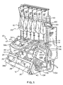
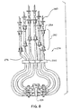
- a preferred embodiment of a fluid transfer assembly of the present invention is generally indicated at 10.
- the illustrated embodiment of the assembly 10 includes a pumping device 12, such as a compounder, examples of which include those compounders set forth in U.S. Patent no 4,712,590 entitled “ELECTRICAL CONNECTION MEANS FOR MULTIPLE BULK COMPOUNDING SYSTEMS"; U.S. Patent no. 4,513,796 entitled “"HIGH SPEED BULK COMPOUNDER” ; and U.S. Patent no. 5,228,485 entitled “FLEXIBLE TUBING OCCLUSION SENSOR", the disclosures of which are incorporated herein by reference.
- the pumping device 12 is shown utilizing a transfer set 14 to place multiple source containers 16 in fluid communication with a receiver or collection container 18.
- individual fluids 20 within the source containers 16 are forced by at least one pump 24 forming a part of the pumping device 12, through the set 14 to the receiver container 18.
- Examples of the receiving container 18 include flexible bags and syringes, among others.
- the pump 24 is a plurality of pumps, preferably six (6) peristaltic pumps 26, 28, 30, 32, 34 and 36 contained within housings 38a, 38b which are placed in a stacked relationship.
- the transfer set 14 includes conduits 40 formed of flexible tubing 44 arranged to form at least a portion of a fluid passageway 46 (Fig. 4a) from the individual source containers 16 to the receiver container 18. To place the pumps 24 in hydraulic contact with fluid 20 in the tubing 44, a portion of each of the tubing 44 is placed around rollers 47 which form a part of the peristaltic pump 26-36 corresponding to the individual segment.
- the peristaltic pump 24 transfers fluid in a particular source container 16 to the receiving container 18 by selective rotary movement of the rollers 47. This movement causes the pump 24 to hydraulically contact the fluid 20 by compressing the walls of the tubing 44 to place a positive pressure on the fluid, thereby forcing the fluid to flow along the tubing.
- Other pumps which hydraulically contact the fluid to create the positive pressure include syringe, or volumetric, or cassette pumps among others
- the pump 24 may include a pump which hydraulically contacts the fluid by creating a negative pressure on the fluid to force the fluid to flow along the tubing.
- the pump 24 may create a vacuum in the collection container 18 or an intermediate chamber (not shown) to force the flow of fluid along the tubing 44.
- each of the peristaltic pumps 26-36 is individually and operatively controlled by a controller indicated generally at 48. Desired quantities of component fluids are transferred by selective operation of the individual pumps 26-36 by the controller 48.
- the controller 48 controls the pumps 26-36 in at least partial dependence on various inputs and data which may be supplied by various sensors, a separate remote controller or the operator.
- the controller 48 is housed within a separate enclosure 50 wired to the housings 38a, 38b but may also be placed elsewhere, such as in one of the housings 38a or 38b.
- the controller 48 includes at least one microprocessor connected to various combinations of volatile and nonvolatile memory.
- the panel 54 has an input keypad 56, and a plurality of display stations 58 corresponding to each of the pumps 26-36. Each of the display stations 58 is also associated with one of the source containers 16 and may be color coded for identification purposes.
- the keypad 56 is a 16 character keypad having digits 0 through 9, a recall key (RCL) and a clear key (CLR) as well as other keys described below.
- each of the display stations 58 includes a volume to be delivered display 60 and corresponding entry key 64; a specific gravity display 66 and entry key 68; and a source component family display 70 and entry key 74.
- the control panel 54 also includes an ID display 76 for the collection container 18 and an alarm display 78.
- the values for the volume to be delivered; the specific gravity; and the solution family of fluid from an individual source container 16 may be manually input or input by a remote controller 80 diagramatically represented in Fig. 4.
- the type of component fluid to be transferred by the associated pump 26-36 is entered by pressing the entry key 74 to scroll through the various types on the display 70 until the proper type is shown.
- the proper values are input using the respective entry key 64, 68 and keypad 56.
- the displayed digits flash to indicate the entry mode of operation.
- Pressing one of the other entry key 64, 68, 74 enters values which have been input and shown on the station display 58. Entry of a value stops the respective display from flashing. If a value is incorrect, the respective entry key 64, 68, 74 is pressed and then a clear key 90 is pressed to zero out the value, and the entry process is repeated.
- the input values may also be loaded into the controller 48 by a remote controller 80.
- a remote controller 80 An example of such an automatic method and assembly for performing such a method is described in U.S. patent no. 4,653,010 entitled “COMPOUNDING SYSTEM” the disclosure of which is incorporated by reference herein.
- the mode keys 94 may include Auto I/D (Al) for when the next patient Identification in a queue is automatically downloaded from the remote controller 80.
- Another mode key 94 is a Manual I/D (MI) key, to query the remote controller 80 to download input values for a particular patient or prescription.
- a third mode key, the Standard Mode (STD) key places the controller 48 into the mode for accepting input values entered using the control panel 50, as set forth above.
- the patient ID When utilizing the remote controller 80, the patient ID may be displayed on the control panel 50 utilizing the volume to be delivered display 60 of one or more of the station 58.
- An identification of the collection container 18 may be displayed on the container ID display 76.
- Other values such as the source or component family fluid identification may also be downloaded by the remote controller.
- the displayed patient and collection container identification may then be checked against records (not shown).
- the source component fluid identification may be checked against the source component connected to that station 54 (and pump 26-36). If the operator determines that all displayed values are correct, the verify key 84 may be pressed.
- the input values for the specific gravity and volume to be delivered for one or more of the component fluids 20 which are to be used can be downloaded from the remote controller 80 to the controller 48 and displayed on the station 58 for verification in a similar manner.
- the collection container 18 such as a flexible bag 98 is operatively attached to a weighing sensor 99, preferably a hung from a load cell 100, which transmits information regarding the weight of the container 18 along with any contents to the controller 48.
- the load cell 100 may be attached to a bracket 101 forming a part of the pumping device 12. Should the weighing sensor 99 take other forms, such as a scale (not shown), the container 18 may need to be placed on the scale to establish the operative contact.
- a transfer tube 104 forming a part of the transfer set 14 may be connected to the collection bag 18 and a junction manifold 106.
- the junction manifold 106 also places all the tubing 44 from the individual source containers 16 in communication with each other. The ends of the tubing 44 are generally bonded to the junction manifold 106 so that the junction block forms a part of the transfer set 14.
- the transfer tube 104 is removably connected to the junction manifold 106 to allow numerous collection containers to be sequentially filled by connection to a single junction manifold.
- a cradle 108 is attached to the housing 38b and configured to accept the junction manifold 106 in only a predetermined desired orientation. As described later, the fit between the cradle 108 and manifold 106 promotes proper attachment of the transfer set 14 to the transferring assembly 10.
- the sensing assembly 200 noninvasively provides an indication of the type of fluid within each of the individual tubing 44 in fluid communication with the corresponding source containers 16.
- the sensing assembly 200 operates by including, at least partially, a sensing method which is described in a basic form in published European Patent Application No. EP 721,103 entitled “APPARATUS FOR IDENTIFYING CONTAINER COMPONENTS USING ELECTRICAL CONDUCTIVITY ", the disclosure of which is incorporated by reference herein.
- the preferred method of the present invention includes sensing electrical characteristics of the tubing 44 and contents of the tubing at predetermined times and positions along the tubing and comparing the readings to produce a distinguishing characteristic of the type of fluid within the tubing.
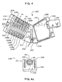
- the sensing assembly 200 includes a housing 202 formed of a base element 204 and a cover element 206 which are attached to each other in a clamshell arrangement.
- the base element 204 and cover element 206 When placed in the closed position (shown in Fig. 1), the base element 204 and cover element 206 define channels 208 for receiving at least a portion of the tubing 44. Because it is desirable to sense each of the fluids, tubing 44 from each of the source containers 16 extends through the corresponding pump 26-36 and along a separate channel 208a-f.
- the individual channels 208a-f are preferably parallel and arranged along a common plane.
- a transmitting element 216 is disposed along the top of each of the respective channels 208a-f.
- a first receiving or sensing element 218 is disposed at a first predetermined distance from the first element 216 and preferably downstream from the first element.
- a second receiving or sensing element 220 is disposed at a second predetermined distance from the transmitting 216 and first receiving element 214 and preferably downstream from the receiving element.
- a signal is applied by the transmitting element 214 to the tubing 44 and any fluid contents at the transmitting element.
- the first receiving element 218 and second receiving element 220 detect the signal after the signal has been transmitted along the tubing 44 and fluid contents. By referencing the detected signal vis-à-vis the applied signal, a distinguishing characteristic of the contents of the tubing 44 may be determined.
- the signal includes a pulse forming a square wave of a predetermined frequency and voltage. This square wave may take on many values such as 5v at about 39 Kilohertz.
- the pulse is applied at the first sensing element 216.
- the first receiving element 218 and second receiving element 220 then acquire the signal.
- the voltage level of the acquired signal is then sampled at a first and a second discrete time after the applied pulse.
- the distinguishing characteristic of the type of fluid may be determined. Air or the absence of liquid in the segment 40 of the tubing 44 proximate one or more of any of the sensing elements 214 is also one of the fluids having a distinguishing characteristic which may be pictured by the desired sensing method.
- sensing elements 214 contact the tubing 44, it is envisioned that the sensing elements may be disposed in other positions and still function to practice the preferred method of the invention. These sensing elements 214 should be in sensory contact with the tubing and contents.
- the sensory contact includes disposing the transmitting 216 and receiving elements 218, 220 so that the signal may be transmitted to the tubing 44 and contents and received from the tubing and contents in such a fashion that the distinguishing characteristic may be determined.
- a magnetic field or electrical pulse of a different wave form may also be used.
- the sensing assembly 200 is also configured so that each channel 208a-f corresponds to one of the pumps 26-36. Thus, fluid pumped by a particular one of the pumps 26-36 is to flow through tubing received in the particular corresponding channel 208a-f.
- One such second method is to distinguish between fluids by examining the flow rates of the fluids while the fluids are being pumped. Fluids frequently possess distinguishing physical characteristics which along with the hydraulic flow resistance found in the transfer set 18 have an effect on the flow rate of the fluid within the set.
- the junciton manifold 106 is an example of a portion of the transfer set 14 which forms hydraulic flow resistance for the flow of fluid through the set.
- dextrose has a higher viscosity than a fluid containing branch chain amino acids.
- the flow rate of dextrose through the transfer set 14 will typically be lower than the flow rate of the source fluid containing branch chain amino acids.
- one way the flow rate differential can be indicated is by a novel use of the weight change per unit of time of the collection container 18 as sensed by the weight sensor 99 and which occurs during pumping.
- the flow rate of each of the fluids 20 through the transfer set 14 depends at least partially on the viscosity of that fluid.
- This variation in flow rate will be, at least partially, indicated in the difference between the weight gain per unit of time for the container 18 as it receives one type of component fluids 20 versus a second type of component fluid.
- the change of the weight of the container 18 per unit of time during pumping will, in many instances, vary between the various fluids, which gives an indication of the flow rate differential and thus the type of the fluid going into the container.
- One particular advantage of using the sensor assembly 200 and weighing sensor 99 in the method described above, is that the identification of the fluids is accomplished by sensing devices which do not require contact with the fluid to function properly. In fact, a disposable transfer set 14 is easily accommodated by these sensing devices.
- the housing 202 is attached to the upper housing 38a.
- the housing 202 is preferably placed at an angle relative to horizontal to facilitate placement of the tubing 44 within the housing and opening of the housing about the bracket 101.
- the housing 202 includes a latching assembly 226 to retain the base element 204 and the cover element 206 in the closed position (shown in Fig. 1).
- both the base element 204 and the cover element 206 of the housing 202 include an outer shell 228 and an inner element 230.
- the channels 208 are defined in the inner element 230 of the base 204 while the surface 231 of the inner element 230 of the cover 206 is generally planar.
- a portion of the channel 208 may be defined in the inner element 230 of both the base 204 and cover 206.
- the transmitting element 216 Disposed along each of the channels are the transmitting element 216, the first receiving element 218 and the second receiving element 220.
- all of the sensing elements 214 are similarly formed.
- the sensing elements 214 are formed as a tubular segment having a "C: shaped cross section and an inner surface 234 forming an interior into which a portion of a length of the tubing 44 is inserted.
- the inner surface 234 is generally circular and is sized to snugly fit about the tubing 44.
- the element 214 is formed so that a central axis 236 of the tubing 44 is interior of, or recessed relative to, a plane 238 defined by edges 240 of the inner surface 234 disposed directly opposite the tube 44.
- the element 214 preferably envelopes a majority of the circumference of the tube. It has been found that the tubing can be easily inserted into an opening defined by the edges 240 with the elements then removably clutching the tubing which promotes intimate contact between the sensing elements and tubing. Such contact facilitates the operation of the sensing assembly 200.
- the outer edge 240 of the element is formed with a smooth radius. It has also been found that the surface texture of the inner surface 234 effects the elements 214 in transmitting or receiving the signals.
- the separation between the elements 214 along a channel 208 may vary, in the preferred embodiment the transmitting element 216 is separated from the first sensing element 218 by approximately 0.2 inches, while the second sensing element 220 is separated from the transmitting element 214 by approximately 1.6 inches.
- the inner elements 230 are composed of a non-conducting polymer and the assembly 200 includes generally planar shields 246 which extend within the inner elements and generally parallel to the channels 208 and along both sides of each of the channels. It has been found that similar shielding is not necessary between the elements 216, 218 and 220 disposed along one of the channels 208.
- the sensing assembly 200 may be adapted so that the transfer tube 104 may also be passed through the sensing assembly. The sensing assembly 200 may then sense the contents of the transfer tubing. Such an arrangement may however, lead to nuisance alarming as the transfer tubing 104 will likely contain fluid from a previous pumping cycle upon the initiation of a second pump 24. Thus the controller 48 may find a mismatch. A delay may be incorporated to reduce this nuisance alarming.
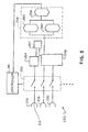
- a block diagram illustrates the general layout of a preferred embodiment of the circuit, indicated generally at 250, forming a part of the sensing assembly 200.
- the controller 48 actuates a switching circuit 252 to activate the sensing elements 214 along a desired channel 208 to sense the fluid in the tubing 44 extending along that channel.
- the circuit 250 is preferably housed in the base 204 (Fig. 4). For example during operation of one of the pumps 24 (Fig. 1), the controller 48 actuates the channel 208a-f corresponding to that pump.
- the controller 98 generally actuates the sensory assembly 200 at predetermined times.
- a signal generator 254 supplies a signal, preferably a pulse consisting of a square wave of a predetermined frequency and voltage to the transmitting element 216.
- the signal is then transmitted by the transmitting element 216 into the tubing 44 (Fig. 1) and the contents of the tubing.
- the signals received at the first receiving element 218 and second receiving element 220 are amplified and transmitted to a sampling circuit 256 which under the direction of a timing circuit 257 samples the amplified signals at predetemined times, preferably two separate times, relative to the transmitted signal.
- the sampled signals are then transmitted to an analyzing circuit 258.
- the analyzing circuit 258 is composed of at least one and preferably two initial lookup circuits 260, where the sampled signals from the first element 218 and second element 220 are compared to stored value ranges representative of tubing containing known source solution types.
- Output from the initial lookup circuits 260 is transmitted to a second lookup circuit 264 which also compares the signals to stored value ranges representative of known source solution types.
- At least one of the initial lookup circuits 260 and second lookup circuit 264 contains a stored value range corresponding to a tube containing air and the sampled signals are also compared to this range.
- a code representative of the corresponding compound fluid type is transmitted to the controller 48. If the signals do not fall within the stored value ranges, an indicative code is returned to the controller 48. If the code indicative of any unidentified fluid type is received, the controller 48 preferably generates an alarm.
- the controller 48 upon starting of the pumping device 12, the controller 48 will check the specific gravity for each of the fluids being pumped by the pumping device with the range of specific gravity for that type of fluid. As noted above, the specific gravity and fluid solution type are both input into the controller 48 for each of the fluids to be pumped. The controller 48 also contains ranges of specific gravity values for the different types of component fluids 20. Upon pushing of the start button 107, the controller 48 compares the specific gravity input into the controller for each of the fluids which are to be pumped by the pumping device 12 to the stored range of specific gravity for that component fluid type. If the input specific gravity does not fall within the stored range, an alarm will sound and the station 58 having the mismatched specific gravity will blink.
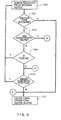
- the sensing assembly 200 supplies a signal to the controller 48 (Fig. 2)indicating the type of fluid within the segment of tube 44 extending through the housing 202, as illustrated by block 300 in the figure.
- the controller 48 determines if the signal indicates that a solution type was identified by the sensing assembly 200 as shown in decision diamond 302. If the solution type was not identified, the controller 48 stops operation of the fluid transfer assembly 10 and sounds an alarm. Referring briefly to Fig. 2, the alarm may be muted by pushing a stop/mute button 109 on the control panel 50.
- the next step is to determine if the sensed fluid type is one of those types of fluids, for example dextrose and branch chain amino acids, for which an additional distinguishing characteristic is desired.
- the sensed fluid is not air, a comparison is made between the sensed type of fluid and the type of fluid which is to be expected from the source container 16 which is connected to the tubing 44 being sensed, as illustrated by decision diamond 308.
- the type of fluid in that source container 16 and which is to be transferred by the pump 26-36 corresponding to the channel 208a-f had been previously input into the controller 48, as described above. If the sensed type matches the input type, the compounder 12 continues in a normal operation and the process is repeated by the supply of the next signal 300.
- the respective pump 24 ceases operation, and an alarm is sounded and displayed on the front face of the panel 54 (Fig. 2), as represented by block 310.
- the display of such an alarm state is preferably achieved by blinking the displayed digits on the corresponding display station 58 for that fluid and an error message such as "incorrect solution" is displayed on the error display 78.
- the change of weight of the container 18 and contents of the container over a predetermined time interval is repeatedly calculated by the controller 48. It has been found that a time interval of 3 seconds provides satisfactory results, although other time intervals may also prove satisfactory.
- the change of weight calculating step is represented by block 312.
- the controller 48 determines if the additional identifying characteristic for the fluid identified by the sensing assembly 200 is desired, as indicated by decision diamond 314. If no additional characteristic is desired, the controller returns to the weight change calculating step.
- This air detection step is represented by decision diamond 316.
- air flowing within the tubing 44 may cause the change of weight of the container 18 and contents to be different than that which would have occurred had there been liquid flow during the entire period. Thus, the weight change may not be indicative of the flow rate of a particular liquid.
- the controller If air in the tubing 44 is detected during the time interval over which the change of weight of container 18 is examined, the controller returns to calculating the change of weight per unit of time.
- the controller 48 compares the weight change with a lookup table of weight changes for a comparable unit of time for various potential component fluids, as represented by block 318. As indicated by decision diamond 320, if the weight change is within a range of stored weight change values for a particular source solution which matches one of the possible source solutions as indicated by the sensing assembly 200, that type of solution is identified, as indicated in block 326, otherwise an alarm is returned.
- the identified solution is then compared with the input solution type as represented in decision diamond 308, described above. If there is no match, the assembly 10 ceases operation and the alarm is sounded. If there is a match the assembly continues normal operation.
- the controller 48 forming a part of the mixing assembly 10 utilizes inputs from the sensing assembly 200, and possibly the weighing sensor 99 to distinguish or identify the type of solution flowing through the particular tubing 44 and into the collection container 18.
- the identified solution is then compared with or checked against the solution type which has been input into the controller 48 for a particular pump 26-36, typically by the operator or remote controller 80. If the types do not match, an alarm condition is sounded and the assembly 10 ceases operation.
- the controller 48 may be remotely located relative to the housings 38a and 38b. Signals may be transmitted by a number of ways between the sensing assembly 200, the controller 48, the load cell 100 and the housings 38a and 38b. Hard wiring is one such way. Another envisioned way is by infrared or radio transmission. Also, the controller 48 may be configured to directly output or cause the output of the signal to the transmitting electrode 216 and read the signal detection inputs from the receiving electrodes 218, 220. The controller 48 may then perform the identification method on the respective signals.
- a calibrating fixture similar in shape to the tubing 44 may be inserted into one of the channels 208.
- a calibration button 113 (Fig. 2) may be pressed and the sensing assembly 200 sends a response to the controller 48 which indicates the proper functioning of the sensing assembly 200.
- the sensing assembly 200 identifies the fluids within all of the tubing which extend through the channels 208. Because the fluid within a particular tubing 44 may not be flowing initially, flow rate identification is not performed. The types of solutions identified by the sensing assembly 200 are compared with the input types of solutions for the corresponding pumps 26-36 and an alarm is sounded if a mismatch is found.
- the controller 24 checks the indicated solution type against the plurality of possible solution types. If a match is found among the plurality, the assembly 10 continues normal operation.
- the controller 48 After initial start up and fluid is being pumped through the tubing 44, the controller 48 identifies the fluid or air in the tubing 44 through which a fluid is flowing, using inputs from both the sensing assembly 200 and, if necessary, the weight change as detected by the weighing sensor 99, as described above. The identified solution type is then matched against the input solution type.
- the alarm is sounded.
- the operator checks to insure that the proper source container 16 is connected to the station 58 displaying the alarm condition.
- the operator may also check to see if the right solution type has been input into the station 58.
- the present invention includes examining the input from the weighing sensor 99 only when the sensing devices 200 determines that the type is one or more of a subset of possible solution types. In other embodiments, the present invention may also include utilizing the input from the weighing sensor 99 regardless of the solution type sensed by the sensing device 200.
- the source solution is correct, and the type of solution may be input correctly into the system, and yet the controller 48 generates a solution mismatch alarm.
- One example of such an occurrence is when the source solution container 16 having a particular solution type is correctly replaced with a container having another type of solution, and the new input solution type is correctly input into the controller 48. Fluid from the first solution type may still be in the tubing 44 with the old solution being sensed by the sensing assembly 200, thereby generating the alarm.
- the transfer set 14 is flushed by depressing the flush switch 110 on the front face 54 of the control panel 50.
- the pump 26-36 corresponding to the alarming station is activated for a brief period or until the new solution is detected, to flush the tubing 44. If the correct solution type is then identified, the compounding may be restarted
- the collection container 18 is then discarded, as indicated to the controller 48 by the removal of the weight from the load cell 100. A new collection container 18 is then hung from the load cell 100, and the compounding process is restarted.
- the controller 48 may also be configured so that it compares the contents of the tubing 44 relative to the operation of one of the pumps 26-36 to sense a free flowing condition. For example, if the controller 48 receives from the sensing assembly 200 designating an empty tubing 44 and then at a later reading receives a code designating liquid in the tubing without the corresponding pump being in operation, a free flow condition may be identified.
- the combining portion 274 includes a plurality of tubing segments 276, One end of each of the tubing segments 276 may be connected to one of source container 14.
- connectors 280 are spikes for accessing ports forming a part of a flexible solution container.
- An intermediate portion 282 of the tubing segments 276 is uniquely configured for operative attachment to one of the pumps 24 and includes retainers 284 to maintain the operative attachment between the tubing 276 and pumps during operation.
- the connector 280 and retainers 284 on a particular one of the tubing segments 276 are color coded to match the color coding on the display station 58 on the control panel 50.
- the color coding is also applied to an entry port 57 of the pump 26-36 that is operatively connected to a single color coded display station 58.
- each of the tubing 276 are connected to the junction manifold 106.
- ensuring that a tube extending from a particular pump 26-36 is threaded through the proper channel 208 is important or there will be a mismatch between the fluid sensed by the sensing assembly 200 and the type of fluid input for that particular pump.
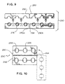
- a bracket 290 is provided to arrange the various tubing 44 so that the individual tubing is placed in the proper corresponding channel 208a-f .
- the bracket 290 retains the individual tubing segments 276 in a predetermined arrangement relative to each other.
- the bracket 290 preferably is formed as two similarly configured portions 292 holding an equal number of tubing.
- the portions 292 are connected to each other by a living hinge 294 attached to a rear comer 292a of one of the portions 292 and the opposing rear corner 292b of the other portion.
- the hinge 294 allows the bracket 290 to fold so that the portions 292 extend along each other to facilitate packaging of the combining portion as particularly shown in Fig. 10.
- the hinge 294 allows the portions 294 to be unfolded to a position where the portions are generally aligned with each other and an abutting interference between the two portions 292 prevents further unfolding as shown in Fig. 9.
- the bracket 290 forms passageways 296 for the tubing 276. Opposing teeth 298 are formed within the passageways 296 to clamp the tubing 276 and prevent slippage of the tubing 276 relative to the bracket 290.
- each of the channels 208 corresponds to a particular pumping station 26-36 to which a component fluid 20 has been identified by input to the controller (Fig. 2). If the proper tubing segment 276 is not inserted into the proper channel as the component fluid flows through the tubing and improper channel 208 where the fluid is sensed by the sensing assembly 200, a nuisance alarm will be generated.
- the bracket 290 makes it very difficult to inadvertently place the wrong tubing segment in a channel 208.
- the bracket 290 in the unfolded position aligns the tubing segments 276 in the proper order relative to each other.
- the bracket 290 is placed at a predetermined distance d1 from the junction manifold 106 along the tubing segments 276. This distance d1 is set by the spacing s1 between the cradle 108 an at least one of the upper edge 200a or lower edge 200b of the sensing assembly 200.
- the distance d1 is set by the spacing between the cradle 108 and upper edge 200a so that when the junction manifold 106 is placed in the cradle 108, the tubing segments may be extended so that the bracket just clears the upper edge.
- the cradle 108 and junction manifold 106 are configured so that the junction manifold can be received in the cradle in only a desired orientation.
- the junction manifold 106 is placed within the cradle 108 and the tubing segments 276 between the bracket 290 and junction manifold are extended so that the bracket clears the upper edge 200a, the proper alignment of the tubing segments becomes self evident.
- Orienting the bracket 290 in the opposite direction causes a corkscrewing of the tubing which reduces the effective length of the tubing so that the junction manifold 106 cannot be received in the proper orientation in the cradle 108.
Abstract
Description
Claims (19)
- An assembly (10) for controllably transferring fluids (20) from a plurality of individual source containers (16) through a transfer set (14) to form a desired mixture in a receiving container (18), the set placing at least one of the source containers in fluid communication with the receiving container, the assembly comprising:a pump (24) operatively acting on at least one of the fluids to force a flow of said fluid along at least a portion of the set, the rate of the flow varying in at least partial dependence on a characteristic of said quid;a flow rate distinguishing sensor in operative contact with the receiving container to determine the difference between flow rates of the fluids to provide a distinguishing characteristic of the fluid;a fluid type sensor (200) in noninvasive sensory contact with the fluid flowing within the set to determine a further distinguishing characteristic of the fluid; and a controller (48) to control the pump (24) in dependence on data supplied by at least the fluid type sensor (200).
- The assembly of claim 1 wherein the flow rate distinguishing sensor includes a weight sensor (99).
- The assembly of claim 2 wherein the flow rate distinguishing sensor includes a load cell (100).
- The assembly of claim 1 wherein the type sensor (200) includes a first sensor (216) configured to transmit a signal into the set (14) and a second sensor (218), configured to receive the signal from the set (14).
- The assembly of claim 4 wherein the type sensor (200) includes a third sensor (220) configured to receive the signal from the set (14).
- The assembly of claim 5 wherein said type sensor (200) and said distinguishing sensor input into said controller, said controller configured to determine the fluid type from at least one of at least three possible fluid types utilizing input from said type sensor and without utilizing the input from the distinguishing sensor.
- The assembly of claim 6 wherein the controller (48) is configured to determine the fluid type from a plurality of said at least three possible fluid types utilizing input from said type sensor (200) and utilizing the input from said distinguishing sensor.
- The assembly of claim 6 wherein the controller (48) is configured to determine the fluid type from a plurality of said at least three possible fluid types utilizing input from said type sensor (200) and only utilizing the input from said distinguishing sensor when said type sensor does not detect air as one of the fluid types detected during a predetermined time interval.
- A method for distinguishing a first fluid component from at least one second component during the mixing of the first and second components in a receiving container (18), the method comprising:placing a first tubing segment (40) providing a passageway (46) for the first component fluid in close proximity to a first noninvasive sensing means (200) for identifying a first distinguishing characteristic of both the first component fluid and the second component fluid;providing a flow rate distinguishing sensor in operative contact with the receiving container to determine the difference between flow rates of the fluids to provide a distinguishing characteristic of the fluid;providing a controller (48) to control a pump (24) in dependence an data supplied by at least the first noninvasive sensor (200);establishing fluid communication between a transfer set (14) and the receiving container (18),pumping one of the first component fluid and second component fluid through the transfer set (14);sensing said distinguishing characteristic of the pumped fluid; anddetermining a second distinguishing characteristic of the pumped fluid, said determining step including correlating the flow rate of the pumped fluid to one of the flow rate of the first component fluid and second component fluid under similar pumping conditions.
- The method of claim 9 wherein said determining step includes performing said determining step in at least partial dependence on the distinguishing characteristic sensed in said sensing step.
- The method of claim 9 further including first identifying a component solution type prior to said pumping, and performing said determining step based on whether said sensing step identifies said first identified component solution.
- The method of claim 9 further including first identifying a component solution type prior to said pumping, wherein said determining step includes determining whether said pumped fluid is one of said first component fluid and said second component fluid based on both said sensing and said first determining step when said distinguishing characteristic from said determining step correlates to said first identified solution.
- The method of claim 9 further including first identifying a component solution type prior to pumping;
second identifying a component solution type in at least partial dependence on said distinguishing characteristic from said sensing step; and
maintaining said pumping only if said first identified solution type matches said second identified solution type. - The method of claim 9 further including first identifying a component solution type prior to said pumping;
second identifying a solution type from said sensing step and said determining step; and
maintaining said pumping only if said first identified solution type matches said second identified solution type. - The assembly of any one of claims 1 to 5, said fluid type sensor (200) indicating said first distinguishing characteristic to said controller and a second sensor indicating a second distinguishing characteristic to said controller, said controller including means for utilizing the indication from said first sensor to determine whether to utilize the indication from said second sensor.
- An assembly according to any one of claims 1 to 5, wherein the transfer set (14) comprises conduits (40) formed of flexible tubing (44) for controllably transferring a first component fluid through a first tubing segment to a receiving container (18) and a second component fluid through a second tubing segment to the receiving container (18), the first tubing segment and second tubing segment being in fluid communication with the receiving container, wherein the pump (24) comprises
a first pump (26) to pump the first component fluid through the first tubing segment
a second pump (28) to pump the second component fluid through the second tubing segment; wherein the fluid type sensor (200) comprises
a first sensing means for noninvasively sensing a distinguishing characteristic of the first component fluid within the first tubing segment;
a second sensing means for noninvasively sensing a distinguishing characteristic of the second component fluid within the second tubing segment; and wherein the flow rate distinguishing sensor comprises
a third sensing means for noninvasively distinguishing the flow rate of the first component when the first fluid is pumped by the first pump. - The assembly of claim 16 wherein the fluid sensed by said first sensing means includes air.
- The assembly of claim 17 further including means utilizing the distinguishing characteristic from said first sensing means for determining the possible fluid types having matching distinguishing characteristics.
- The assembly of claim 18 wherein the determining means includes means utilizing the distinguishing characteristic supplied by the first sensing means for determining whether to utilize the distinguishing characteristic sensed by said third sensing means.
Applications Claiming Priority (3)
| Application Number | Priority Date | Filing Date | Title |
|---|---|---|---|
| US762578 | 1996-12-09 | ||
| US08/762,578 US5927349A (en) | 1996-12-09 | 1996-12-09 | Compounding assembly for nutritional fluids |
| PCT/US1997/021159 WO1998025570A1 (en) | 1996-12-09 | 1997-11-19 | Compounding assembly for nutritional fluids |
Publications (2)
| Publication Number | Publication Date |
|---|---|
| EP0886513A1 EP0886513A1 (en) | 1998-12-30 |
| EP0886513B1 true EP0886513B1 (en) | 2003-04-16 |
Family
ID=25065468
Family Applications (1)
| Application Number | Title | Priority Date | Filing Date |
|---|---|---|---|
| EP97948390A Expired - Lifetime EP0886513B1 (en) | 1996-12-09 | 1997-11-19 | Compounding assembly for nutritional fluids |
Country Status (18)
| Country | Link |
|---|---|
| US (3) | US5927349A (en) |
| EP (1) | EP0886513B1 (en) |
| JP (2) | JP2000506425A (en) |
| KR (1) | KR100499301B1 (en) |
| CN (1) | CN1140245C (en) |
| AT (1) | ATE237297T1 (en) |
| AU (1) | AU718362B2 (en) |
| BR (1) | BR9707626A (en) |
| CA (1) | CA2243960C (en) |
| CO (1) | CO4750848A1 (en) |
| DE (1) | DE69720981T2 (en) |
| DK (1) | DK0886513T3 (en) |
| ES (1) | ES2197374T3 (en) |
| ID (1) | ID20422A (en) |
| MX (1) | MX9806185A (en) |
| MY (1) | MY118402A (en) |
| PT (1) | PT886513E (en) |
| WO (1) | WO1998025570A1 (en) |
Families Citing this family (65)
| Publication number | Priority date | Publication date | Assignee | Title |
|---|---|---|---|---|
| US5927349A (en) | 1996-12-09 | 1999-07-27 | Baxter International Inc. | Compounding assembly for nutritional fluids |
| US6199603B1 (en) * | 1998-08-14 | 2001-03-13 | Baxter International Inc. | Compounding assembly for nutritional fluids |
| DE19939219C2 (en) * | 1999-08-18 | 2001-10-18 | Fritz Giebler Gmbh | Device for producing mixtures of pharmaceutical liquids |
| EP1656988B2 (en) * | 1999-12-03 | 2017-07-12 | Baxter International Inc. | Method and apparatus for controlling the strategy of compounding pharmaceutical admixtures |
| MXPA01007901A (en) * | 1999-12-03 | 2002-04-24 | Baxter Int | Method and apapratus for controlling the strategy of compounding pharmaceutical admixtures. |
| US6975924B2 (en) * | 1999-12-03 | 2005-12-13 | Baxter International Inc. | Method and apparatus for controlling the strategy of compounding pharmaceutical admixtures |
| US6450215B1 (en) * | 2000-09-29 | 2002-09-17 | Charter Medical, Ltd. | Apparatus and method for filling bags |
| JP2004537338A (en) * | 2001-03-02 | 2004-12-16 | ユーロ−セルティーク,エス.エイ. | Method and apparatus for preparing individual dosage forms |
| US20040217236A1 (en) * | 2001-03-28 | 2004-11-04 | Tomio Shibuya | Vibration-proof clamp |
| US7343224B2 (en) * | 2001-12-31 | 2008-03-11 | B. Braun Medical Inc. | Pharmaceutical compounding systems and methods and information management system for same |
| US7317967B2 (en) * | 2001-12-31 | 2008-01-08 | B. Braun Medical Inc. | Apparatus and method for transferring data to a pharmaceutical compounding system |
| MXPA04006493A (en) * | 2001-12-31 | 2005-03-31 | Braun Medical Inc | Pharmaceutical compounding information management system. |
| KR100744734B1 (en) * | 2003-06-06 | 2007-08-01 | 이-지-이엠, 인코포레이티드 | Peristaltic syringe filling station |
| US7703483B2 (en) | 2004-06-04 | 2010-04-27 | Acist Medical Systems, Inc. | Peristaltic syringe filling station |
| US6951228B2 (en) * | 2003-12-04 | 2005-10-04 | B Braun Medical Inc. | Bulk compounder manifold |
| US7204277B2 (en) * | 2004-09-16 | 2007-04-17 | B. Braun Medical Inc. | By-pass line connector for compounding system |
| EP1866611B1 (en) * | 2005-03-17 | 2014-09-10 | Colder Products Company | Coupling device |
| US10631558B2 (en) | 2006-03-06 | 2020-04-28 | The Coca-Cola Company | Methods and apparatuses for making compositions comprising an acid and an acid degradable component and/or compositions comprising a plurality of selectable components |
| CN101443590A (en) * | 2006-03-13 | 2009-05-27 | 考尔得产品公司 | Connection state sensing for coupling device |
| US7981082B2 (en) * | 2007-08-21 | 2011-07-19 | Hospira, Inc. | System and method for reducing air bubbles in a fluid delivery line |
| US8162176B2 (en) | 2007-09-06 | 2012-04-24 | The Coca-Cola Company | Method and apparatuses for providing a selectable beverage |
| US8225824B2 (en) * | 2007-11-16 | 2012-07-24 | Intelligent Hospital Systems, Ltd. | Method and apparatus for automated fluid transfer operations |
| US9026370B2 (en) | 2007-12-18 | 2015-05-05 | Hospira, Inc. | User interface improvements for medical devices |
| JP5361438B2 (en) | 2009-02-23 | 2013-12-04 | 三洋電機株式会社 | Solar cell module |
| US20160354281A1 (en) * | 2009-03-03 | 2016-12-08 | Bryan M. O'NEILL | Automated transfer of liquid medicament from containers |
| ES2605804T3 (en) | 2010-08-20 | 2017-03-16 | Graco Minnesota Inc. | Procedure to synchronize a linear pump system |
| DE102011016767A1 (en) * | 2011-04-12 | 2012-10-18 | Sartorius Stedim Biotech Gmbh | Use of a device and a process for the preparation of pharmaceutical mixtures |
| US10786432B2 (en) | 2011-04-12 | 2020-09-29 | Sartorius Stedim Biotech Gmbh | Use of a device and a method for preparing mixtures of pharmaceutical substances |
| US9240002B2 (en) | 2011-08-19 | 2016-01-19 | Hospira, Inc. | Systems and methods for a graphical interface including a graphical representation of medical data |
| US10022498B2 (en) | 2011-12-16 | 2018-07-17 | Icu Medical, Inc. | System for monitoring and delivering medication to a patient and method of using the same to minimize the risks associated with automated therapy |
| AU2013239778B2 (en) | 2012-03-30 | 2017-09-28 | Icu Medical, Inc. | Air detection system and method for detecting air in a pump of an infusion system |
| CA3089257C (en) | 2012-07-31 | 2023-07-25 | Icu Medical, Inc. | Patient care system for critical medications |
| US20140061421A1 (en) * | 2012-08-29 | 2014-03-06 | Daniel G. J. Lane | Iv organizer and locking device |
| US9814828B2 (en) * | 2013-03-15 | 2017-11-14 | Aesynt Incorporated | Method and apparatus for preparing and monitoring an intravenous fluid bag |
| AU2014268355B2 (en) | 2013-05-24 | 2018-06-14 | Icu Medical, Inc. | Multi-sensor infusion system for detecting air or an occlusion in the infusion system |
| CA2913915C (en) | 2013-05-29 | 2022-03-29 | Hospira, Inc. | Infusion system which utilizes one or more sensors and additional information to make an air determination regarding the infusion system |
| CA2913918C (en) | 2013-05-29 | 2022-02-15 | Hospira, Inc. | Infusion system and method of use which prevents over-saturation of an analog-to-digital converter |
| US9579257B2 (en) | 2013-08-20 | 2017-02-28 | Anutra Medical, Inc. | Haptic feedback and audible output syringe |
| ES2776363T3 (en) | 2014-02-28 | 2020-07-30 | Icu Medical Inc | Infusion set and method using dual wavelength in-line optical air detection |
| AU2015266706B2 (en) | 2014-05-29 | 2020-01-30 | Icu Medical, Inc. | Infusion system and pump with configurable closed loop delivery rate catch-up |
| EP2952216A1 (en) * | 2014-06-05 | 2015-12-09 | Hemedis GmbH | Device for providing a mixing solution consisting of a plurality of components |
| USD763433S1 (en) | 2014-06-06 | 2016-08-09 | Anutra Medical, Inc. | Delivery system cassette |
| USD774182S1 (en) | 2014-06-06 | 2016-12-13 | Anutra Medical, Inc. | Anesthetic delivery device |
| US20150374585A1 (en) * | 2014-06-30 | 2015-12-31 | Carefusion 303, Inc. | System and method for compounding medication |
| WO2016077534A1 (en) | 2014-11-12 | 2016-05-19 | The General Hospital Corporation | Flow rate measurement and control of infusion devices |
| US11344668B2 (en) | 2014-12-19 | 2022-05-31 | Icu Medical, Inc. | Infusion system with concurrent TPN/insulin infusion |
| US10850024B2 (en) | 2015-03-02 | 2020-12-01 | Icu Medical, Inc. | Infusion system, device, and method having advanced infusion features |
| WO2016196810A1 (en) * | 2015-06-04 | 2016-12-08 | B. Braun Medical Inc. | Compounding device, system, kit, software, and method |
| US10549248B2 (en) * | 2015-04-23 | 2020-02-04 | B. Braun Medical Inc. | Compounding device system, software and method for controlling the process of compounding admixtures |
| US11357966B2 (en) * | 2015-04-23 | 2022-06-14 | B. Braun Medical Inc. | Compounding device, system, kit, software, and method |
| ES2754081T3 (en) * | 2015-05-22 | 2020-04-15 | Braun Medical Inc | Composition device |
| US10925808B2 (en) * | 2015-12-04 | 2021-02-23 | Carefusion 303, Inc. | Tube management structures for automatic drug compounder |
| PL3429546T3 (en) * | 2016-03-15 | 2023-07-17 | Fresenius Kabi Deutschland Gmbh | Method for preparing a medical preparation |
| EP3795132A3 (en) | 2016-03-15 | 2021-07-21 | Fresenius Kabi Deutschland GmbH | System for producing a medical preparation |
| ES2945432T3 (en) * | 2016-03-15 | 2023-07-03 | Fresenius Kabi Deutschland Gmbh | Procedure for producing a medicinal preparation using a peristaltic pump |
| AU2017264784B2 (en) | 2016-05-13 | 2022-04-21 | Icu Medical, Inc. | Infusion pump system and method with common line auto flush |
| EP3468635A4 (en) | 2016-06-10 | 2019-11-20 | ICU Medical, Inc. | Acoustic flow sensor for continuous medication flow measurements and feedback control of infusion |
| US10060571B2 (en) * | 2016-06-21 | 2018-08-28 | Pedigo Products, Inc. | Hook attachment for mobile stand for use with intravenous delivery of medications |
| US10089055B1 (en) | 2017-12-27 | 2018-10-02 | Icu Medical, Inc. | Synchronized display of screen content on networked devices |
| US11278671B2 (en) | 2019-12-04 | 2022-03-22 | Icu Medical, Inc. | Infusion pump with safety sequence keypad |
| US11559469B2 (en) * | 2020-01-24 | 2023-01-24 | BBraun Medical Inc. | Systems and methods for controlling the process of compounding admixtures |
| IT202000009745A1 (en) * | 2020-05-04 | 2021-11-04 | Biovalley Group S P A | APPARATUS FOR PREPARING A DRUG, WEIGHING DEVICE INCLUDED IN THE APPARATUS, AND METHOD FOR PREPARING THE DRUG |
| AU2021311443A1 (en) | 2020-07-21 | 2023-03-09 | Icu Medical, Inc. | Fluid transfer devices and methods of use |
| KR102500355B1 (en) | 2020-09-18 | 2023-02-16 | 서울대학교 산학협력단 | System for the Prevention of Drug Hypersensitivity |
| US11135360B1 (en) | 2020-12-07 | 2021-10-05 | Icu Medical, Inc. | Concurrent infusion with common line auto flush |
Family Cites Families (65)
| Publication number | Priority date | Publication date | Assignee | Title |
|---|---|---|---|---|
| US3233173A (en) * | 1958-04-28 | 1966-02-01 | United Res Inc | Method of determining the volume of particles in a mixture |
| US3155898A (en) * | 1960-07-11 | 1964-11-03 | Industrial Nucleonics Corp | Method and apparatus for measuring multiple properties of material by applying electric fields at multiple frequencies and combining detection signals |
| US3643507A (en) * | 1970-11-12 | 1972-02-22 | Combustion Eng | Means for determining flow rate and volume of a flowing fluid mass |
| US3774238A (en) * | 1971-12-09 | 1973-11-20 | Spearhead Inc | Three-terminal capacitive apparatus for remotely responding to a condition or dielectric properties of a material |
| US4063153A (en) * | 1976-08-31 | 1977-12-13 | Auburn International, Inc. | Vapor liquid fraction determination |
| DE2837102A1 (en) * | 1977-08-27 | 1979-03-01 | Malcom Ellis Liverpool | MEASURING CELL FOR MEASURING AND MONITORING THE ELECTRICAL CONDUCTIVITY OF A LIQUID |
| US4266188A (en) * | 1979-11-30 | 1981-05-05 | Mobil Oil Corporation | Method and apparatus for measuring a component in a flow stream |
| US4410981A (en) * | 1981-01-28 | 1983-10-18 | Rca Corporation | Simplified transmission system for sequential time-compression of two signals |
| US4475666A (en) * | 1981-08-31 | 1984-10-09 | American Hospital Supply Corporation | Automated liquid dispenser control |
| JPS5829450A (en) * | 1981-08-18 | 1983-02-21 | 株式会社豊田中央研究所 | Hematocrit measuring apparatus |
| US4467844A (en) * | 1982-06-24 | 1984-08-28 | Baxter Travenol Laboratories, Inc. | Flow monitoring method and apparatus |
| US4513796A (en) * | 1982-06-24 | 1985-04-30 | Baxter Travenol Laboratories, Inc. | High speed bulk compounder |
| US4590431A (en) * | 1983-12-21 | 1986-05-20 | The United States Of America As Represented By The Department Of Energy | Induction voidmeter |
| US5100380A (en) * | 1984-02-08 | 1992-03-31 | Abbott Laboratories | Remotely programmable infusion system |
| IL74236A (en) * | 1984-02-08 | 1990-07-12 | Omni Flow Inc | Infusion system having plural fluid input ports and at least one patient output port |
| US4648430A (en) * | 1984-06-22 | 1987-03-10 | Baxter Travenol Laboratories, Inc. | Device and method for collecting a desired weight amount of a material |
| ZA854453B (en) * | 1984-06-22 | 1986-02-26 | Baxter Travenol Lab | Device and method for collecting a desired weight amount of a material |
| US4653010A (en) * | 1984-10-26 | 1987-03-24 | Baxter Travenol Laboratories, Inc. | Compounding system |
| US4807676A (en) * | 1985-02-26 | 1989-02-28 | Baxter International Inc. | Fluid transfer workstation |
| EP0227949B1 (en) * | 1985-11-26 | 1993-10-13 | Dai Nippon Insatsu Kabushiki Kaisha | Device for controlling the concentration of aqueous solution of alcohol |
| US4935207A (en) * | 1986-04-01 | 1990-06-19 | The Johns Hopkins University | Capacitive chemical sensor using an ion exchange surface |
| GB8612020D0 (en) * | 1986-05-16 | 1986-06-25 | Shell Int Research | Misfuelling prevention device |
| US4712590A (en) * | 1986-05-30 | 1987-12-15 | Baxter Travenol Laboratories, Inc. | Electrical connection means for multiple bulk compounding systems |
| JPS638662U (en) * | 1986-07-04 | 1988-01-20 | ||
| US5056568A (en) * | 1986-12-05 | 1991-10-15 | Clintec Nutrition Company | Automated system for adding multiple fluids to a single container |
| US5076332A (en) * | 1986-12-08 | 1991-12-31 | Clintec Nitrition Co. | Arch geometry to eliminate tubing influence on load cell accuracy |
| US4769001A (en) * | 1987-02-25 | 1988-09-06 | Baxter International Inc. | Method and apparatus for calibrating plural pump fluid flow system |
| US5209275A (en) * | 1987-07-09 | 1993-05-11 | Junkosha Co., Ltd. | Liquid dispensing apparatus and method by sensing the type of liquid vapors in the receiver |
| US4925444A (en) * | 1987-08-07 | 1990-05-15 | Baxter Travenol Laboratories, Inc. | Closed multi-fluid delivery system and method |
| JP2600188B2 (en) * | 1987-08-12 | 1997-04-16 | 澁谷工業株式会社 | Weight filling device |
| US4751476A (en) * | 1987-09-21 | 1988-06-14 | Fisher Scientific Company | Detector device and method for distinguishing between fluids having different dielectric properties |
| US4899101A (en) * | 1988-01-21 | 1990-02-06 | The United States Of America As Represented By The United States Department Of Energy | Online capacitive densitometer |
| JPH01204675A (en) * | 1988-02-10 | 1989-08-17 | Takeo Suzuki | Method for informing liquid amount remaining in instillator container |
| DE3822344C2 (en) * | 1988-07-01 | 1997-04-24 | Captron Electronic Fertigungs | Device for measuring properties of a liquid which influence the dielectric behavior |
| JPH0238988A (en) * | 1988-07-29 | 1990-02-08 | Murata Mfg Co Ltd | Liquid sensor |
| US5153827A (en) * | 1989-01-30 | 1992-10-06 | Omni-Flow, Inc. | An infusion management and pumping system having an alarm handling system |
| US4924702A (en) * | 1989-03-10 | 1990-05-15 | Kavlico Corporation | Liquid level sensor |
| US5033644A (en) * | 1989-03-31 | 1991-07-23 | Tentler Michael L | Precision dispensing of varying viscosity fluids in a prescribed mix ratio |
| US4928065A (en) * | 1989-03-31 | 1990-05-22 | E. I. Du Pont De Nemours And Company | Voltammetry in low-permitivity suspensions |
| US5040699A (en) * | 1989-05-15 | 1991-08-20 | Gangemi Ronald J | Fluid compounding method and apparatus |
| CA2025076A1 (en) * | 1990-01-02 | 1991-07-03 | John David Marrelli | Means and method for analyzing a petroleum stream |
| US5208544A (en) * | 1990-09-26 | 1993-05-04 | E. I. Du Pont De Nemours And Company | Noninvasive dielectric sensor and technique for measuring polymer properties |
| US5296843A (en) * | 1991-03-28 | 1994-03-22 | Sd Laboratories, Inc. | Fluid or vapor diagnostic device |
| US5213142A (en) * | 1991-03-04 | 1993-05-25 | Amoco Corporation | Stage II vapor recovery system |
| US5260665A (en) * | 1991-04-30 | 1993-11-09 | Ivac Corporation | In-line fluid monitor system and method |
| US5239860A (en) * | 1991-05-13 | 1993-08-31 | General Motors Corporation | Sensor for measuring alcohol content of alcohol/gasoline fuel mixtures |
| US5255656A (en) * | 1991-06-27 | 1993-10-26 | Borg-Warner Automotive, Inc. | Alcohol concentration sensor for automotive fuels |
| ES2146709T3 (en) * | 1991-08-21 | 2000-08-16 | Smith & Nephew Inc | FLUID CONTROL SYSTEM. |
| US5289132A (en) * | 1991-12-04 | 1994-02-22 | Oksman Henry C | Voltage characteristic comparator for discriminating solutions |
| WO1993012825A1 (en) * | 1991-12-20 | 1993-07-08 | Abbott Laboratories | Automated drug infusion system with autopriming |
| US5266899A (en) * | 1992-01-31 | 1993-11-30 | Akzo N.V. | Salt analyzer switchably capable of employing contact and non-contact conductivity probes |
| US5382232A (en) * | 1992-03-13 | 1995-01-17 | Ivac Corporation | Infusion system with air-in-line clear function |
| AU662203B2 (en) * | 1992-04-03 | 1995-08-24 | Baxter International Inc. | Improved transfer set |
| US5313992A (en) * | 1992-12-11 | 1994-05-24 | Abbott Laboratories | Transfer tubing set for compounding solutions |
| US5645531A (en) * | 1993-05-26 | 1997-07-08 | Quest Medical, Inc. | Constant pressure blood mixture delivery system and method |
| DE4320365C2 (en) * | 1993-06-19 | 2000-07-13 | Uvo Hoelscher | Multi-channel dosing system |
| US5404920A (en) * | 1993-10-15 | 1995-04-11 | Custer; Joseph L. | Automated fluid charging apparatus |
| ATE181844T1 (en) * | 1993-12-29 | 1999-07-15 | Braun Melsungen Ag | INFUSION SYSTEM WITH REGULATORY DEVICE |
| US5609576A (en) * | 1994-09-13 | 1997-03-11 | Ivac Medical Systems, Inc. | Fluid flow impedance monitoring system |
| US5510621A (en) * | 1994-10-03 | 1996-04-23 | Optical Solutions, Inc. | Apparatus and method for measuring components in a bag |
| US5522798A (en) * | 1994-10-17 | 1996-06-04 | Abbott Laboratories | Control of a multi-channel drug infusion pump using a pharmacokinetic model |
| US5612622A (en) * | 1994-12-28 | 1997-03-18 | Optical Solutions, Inc. | Apparatus for identifying particular entities in a liquid using electrical conductivity characteristics |
| US5653681A (en) * | 1995-06-06 | 1997-08-05 | Cobe Laboratories, Inc. | Method and system for obtaining target infusion dosage |
| US5820048A (en) * | 1996-04-09 | 1998-10-13 | Illinois Tool Works Inc. | Side latching hinge mechanism |
| US5927349A (en) | 1996-12-09 | 1999-07-27 | Baxter International Inc. | Compounding assembly for nutritional fluids |
-
1996
- 1996-12-09 US US08/762,578 patent/US5927349A/en not_active Expired - Fee Related
-
1997
- 1997-11-19 JP JP10526689A patent/JP2000506425A/en not_active Withdrawn
- 1997-11-19 EP EP97948390A patent/EP0886513B1/en not_active Expired - Lifetime
- 1997-11-19 DE DE69720981T patent/DE69720981T2/en not_active Expired - Lifetime
- 1997-11-19 WO PCT/US1997/021159 patent/WO1998025570A1/en active IP Right Grant
- 1997-11-19 CA CA002243960A patent/CA2243960C/en not_active Expired - Fee Related
- 1997-11-19 PT PT97948390T patent/PT886513E/en unknown
- 1997-11-19 KR KR10-1998-0706119A patent/KR100499301B1/en not_active IP Right Cessation
- 1997-11-19 AT AT97948390T patent/ATE237297T1/en active
- 1997-11-19 CN CNB97192158XA patent/CN1140245C/en not_active Expired - Fee Related
- 1997-11-19 AU AU54470/98A patent/AU718362B2/en not_active Ceased
- 1997-11-19 ES ES97948390T patent/ES2197374T3/en not_active Expired - Lifetime
- 1997-11-19 ID IDW980061A patent/ID20422A/en unknown
- 1997-11-19 DK DK97948390T patent/DK0886513T3/en active
- 1997-11-19 BR BR9707626A patent/BR9707626A/en not_active IP Right Cessation
- 1997-11-28 MY MYPI97005752A patent/MY118402A/en unknown
- 1997-12-09 CO CO97071823A patent/CO4750848A1/en unknown
-
1998
- 1998-07-31 MX MX9806185A patent/MX9806185A/en unknown
-
1999
- 1999-02-24 US US09/256,973 patent/US6079462A/en not_active Expired - Lifetime
-
2000
- 2000-04-17 US US09/550,738 patent/US6202711B1/en not_active Expired - Lifetime
-
2008
- 2008-08-05 JP JP2008202458A patent/JP4560572B2/en not_active Expired - Fee Related
Also Published As
| Publication number | Publication date |
|---|---|
| MX9806185A (en) | 1998-10-31 |
| ES2197374T3 (en) | 2004-01-01 |
| WO1998025570A1 (en) | 1998-06-18 |
| AU5447098A (en) | 1998-07-03 |
| ID20422A (en) | 1998-12-10 |
| DE69720981D1 (en) | 2003-05-22 |
| CA2243960A1 (en) | 1998-06-18 |
| US6202711B1 (en) | 2001-03-20 |
| CO4750848A1 (en) | 1999-03-31 |
| KR19990082388A (en) | 1999-11-25 |
| JP4560572B2 (en) | 2010-10-13 |
| ATE237297T1 (en) | 2003-05-15 |
| BR9707626A (en) | 1999-07-27 |
| US5927349A (en) | 1999-07-27 |
| PT886513E (en) | 2003-09-30 |
| AU718362B2 (en) | 2000-04-13 |
| CN1140245C (en) | 2004-03-03 |
| KR100499301B1 (en) | 2005-09-09 |
| US6079462A (en) | 2000-06-27 |
| DK0886513T3 (en) | 2003-08-04 |
| DE69720981T2 (en) | 2004-08-19 |
| JP2009039536A (en) | 2009-02-26 |
| CN1210458A (en) | 1999-03-10 |
| JP2000506425A (en) | 2000-05-30 |
| CA2243960C (en) | 2005-09-06 |
| MY118402A (en) | 2004-10-30 |
| EP0886513A1 (en) | 1998-12-30 |
Similar Documents
| Publication | Publication Date | Title |
|---|---|---|
| EP0886513B1 (en) | Compounding assembly for nutritional fluids | |
| EP1014915B1 (en) | Compounding assembly for nutritional fluids | |
| EP2173403B1 (en) | Dialysis fluid measurement systems using conductive contacts | |
| US5207642A (en) | Closed multi-fluid delivery system and method | |
| EP2526979B1 (en) | Enhanced signal detection for access disconnection systems | |
| US5056568A (en) | Automated system for adding multiple fluids to a single container | |
| US20090007642A1 (en) | Dialysis fluid measurement method and apparatus using conductive contacts | |
| US5840058A (en) | Infusion pump with disposable tubing and size indicating means | |
| KR20210039405A (en) | Peritoneal dialysis system configured to diagnose peritonitis with sensors | |
| EP0293444B1 (en) | Automated system for adding multiple fluids to a single container | |
| US20230321332A1 (en) | Capacitive priming sensor for a medical fluid delivery system | |
| JPS59501146A (en) | High speed bulk compounding equipment | |
| MXPA00003688A (en) | Beam current detection and control system for a cathode ray tube | |
| CN115040416A (en) | Enteral nutrition infusion flow rate monitor capable of automatically flushing tube | |
| Huey | Setting up and troubleshooting | |
| Shilipetar et al. | Microcomputer Peritoneal Programmer in Service of Acute Peritoneal Dialysis |
Legal Events
| Date | Code | Title | Description |
|---|---|---|---|
| PUAI | Public reference made under article 153(3) epc to a published international application that has entered the european phase |
Free format text: ORIGINAL CODE: 0009012 |
|
| 17P | Request for examination filed |
Effective date: 19980720 |
|
| AK | Designated contracting states |
Kind code of ref document: A1 Designated state(s): AT BE CH DE DK ES FI FR GB IE IT LI NL PT SE |
|
| 17Q | First examination report despatched |
Effective date: 20010209 |
|
| GRAH | Despatch of communication of intention to grant a patent |
Free format text: ORIGINAL CODE: EPIDOS IGRA |
|
| GRAH | Despatch of communication of intention to grant a patent |
Free format text: ORIGINAL CODE: EPIDOS IGRA |
|
| GRAA | (expected) grant |
Free format text: ORIGINAL CODE: 0009210 |
|
| AK | Designated contracting states |
Designated state(s): AT BE CH DE DK ES FI FR GB IE IT LI NL PT SE |
|
| REG | Reference to a national code |
Ref country code: GB Ref legal event code: FG4D |
|
| REG | Reference to a national code |
Ref country code: CH Ref legal event code: EP |
|
| REF | Corresponds to: |
Ref document number: 69720981 Country of ref document: DE Date of ref document: 20030522 Kind code of ref document: P |
|
| REG | Reference to a national code |
Ref country code: IE Ref legal event code: FG4D |
|
| REG | Reference to a national code |
Ref country code: SE Ref legal event code: TRGR |
|
| REG | Reference to a national code |
Ref country code: CH Ref legal event code: NV Representative=s name: KELLER & PARTNER PATENTANWAELTE AG |
|
| REG | Reference to a national code |
Ref country code: DK Ref legal event code: T3 |
|
| REG | Reference to a national code |
Ref country code: PT Ref legal event code: SC4A Free format text: AVAILABILITY OF NATIONAL TRANSLATION Effective date: 20030716 |
|
| ET | Fr: translation filed | ||
| REG | Reference to a national code |
Ref country code: ES Ref legal event code: FG2A Ref document number: 2197374 Country of ref document: ES Kind code of ref document: T3 |
|
| PLBE | No opposition filed within time limit |
Free format text: ORIGINAL CODE: 0009261 |
|
| STAA | Information on the status of an ep patent application or granted ep patent |
Free format text: STATUS: NO OPPOSITION FILED WITHIN TIME LIMIT |
|
| 26N | No opposition filed |
Effective date: 20040119 |
|
| PGFP | Annual fee paid to national office [announced via postgrant information from national office to epo] |
Ref country code: FI Payment date: 20091130 Year of fee payment: 13 |
|
| PGFP | Annual fee paid to national office [announced via postgrant information from national office to epo] |
Ref country code: NL Payment date: 20091123 Year of fee payment: 13 |
|
| PGFP | Annual fee paid to national office [announced via postgrant information from national office to epo] |
Ref country code: PT Payment date: 20091109 Year of fee payment: 13 |
|
| PGFP | Annual fee paid to national office [announced via postgrant information from national office to epo] |
Ref country code: IE Payment date: 20101124 Year of fee payment: 14 Ref country code: DK Payment date: 20101125 Year of fee payment: 14 |
|
| PGFP | Annual fee paid to national office [announced via postgrant information from national office to epo] |
Ref country code: CH Payment date: 20101124 Year of fee payment: 14 |
|
| PGFP | Annual fee paid to national office [announced via postgrant information from national office to epo] |
Ref country code: IT Payment date: 20101124 Year of fee payment: 14 |
|
| REG | Reference to a national code |
Ref country code: PT Ref legal event code: MM4A Free format text: LAPSE DUE TO NON-PAYMENT OF FEES Effective date: 20110519 |
|
| REG | Reference to a national code |
Ref country code: NL Ref legal event code: V1 Effective date: 20110601 |
|
| PGFP | Annual fee paid to national office [announced via postgrant information from national office to epo] |
Ref country code: ES Payment date: 20101125 Year of fee payment: 14 |
|
| PG25 | Lapsed in a contracting state [announced via postgrant information from national office to epo] |
Ref country code: PT Free format text: LAPSE BECAUSE OF NON-PAYMENT OF DUE FEES Effective date: 20110519 |
|
| PG25 | Lapsed in a contracting state [announced via postgrant information from national office to epo] |
Ref country code: NL Free format text: LAPSE BECAUSE OF NON-PAYMENT OF DUE FEES Effective date: 20110601 Ref country code: FI Free format text: LAPSE BECAUSE OF NON-PAYMENT OF DUE FEES Effective date: 20101119 |
|
| REG | Reference to a national code |
Ref country code: CH Ref legal event code: PL |
|
| REG | Reference to a national code |
Ref country code: DK Ref legal event code: EBP |
|
| PG25 | Lapsed in a contracting state [announced via postgrant information from national office to epo] |
Ref country code: LI Free format text: LAPSE BECAUSE OF NON-PAYMENT OF DUE FEES Effective date: 20111130 Ref country code: CH Free format text: LAPSE BECAUSE OF NON-PAYMENT OF DUE FEES Effective date: 20111130 |
|
| REG | Reference to a national code |
Ref country code: IE Ref legal event code: MM4A |
|
| PG25 | Lapsed in a contracting state [announced via postgrant information from national office to epo] |
Ref country code: IT Free format text: LAPSE BECAUSE OF NON-PAYMENT OF DUE FEES Effective date: 20111119 |
|
| PG25 | Lapsed in a contracting state [announced via postgrant information from national office to epo] |
Ref country code: DK Free format text: LAPSE BECAUSE OF NON-PAYMENT OF DUE FEES Effective date: 20111130 Ref country code: IE Free format text: LAPSE BECAUSE OF NON-PAYMENT OF DUE FEES Effective date: 20111119 |
|
| PGFP | Annual fee paid to national office [announced via postgrant information from national office to epo] |
Ref country code: FR Payment date: 20121206 Year of fee payment: 16 Ref country code: DE Payment date: 20121128 Year of fee payment: 16 |
|
| PGFP | Annual fee paid to national office [announced via postgrant information from national office to epo] |
Ref country code: BE Payment date: 20121129 Year of fee payment: 16 Ref country code: GB Payment date: 20121126 Year of fee payment: 16 Ref country code: SE Payment date: 20121126 Year of fee payment: 16 |
|
| PGFP | Annual fee paid to national office [announced via postgrant information from national office to epo] |
Ref country code: AT Payment date: 20121102 Year of fee payment: 16 |
|
| REG | Reference to a national code |
Ref country code: ES Ref legal event code: FD2A Effective date: 20130604 |
|
| PG25 | Lapsed in a contracting state [announced via postgrant information from national office to epo] |
Ref country code: ES Free format text: LAPSE BECAUSE OF NON-PAYMENT OF DUE FEES Effective date: 20111120 |
|
| BERE | Be: lapsed |
Owner name: *BAXTER INTERNATIONAL INC. Effective date: 20131130 |
|
| REG | Reference to a national code |
Ref country code: SE Ref legal event code: EUG |
|
| REG | Reference to a national code |
Ref country code: AT Ref legal event code: MM01 Ref document number: 237297 Country of ref document: AT Kind code of ref document: T Effective date: 20131119 |
|
| GBPC | Gb: european patent ceased through non-payment of renewal fee |
Effective date: 20131119 |
|
| REG | Reference to a national code |
Ref country code: FR Ref legal event code: ST Effective date: 20140731 |
|
| REG | Reference to a national code |
Ref country code: DE Ref legal event code: R119 Ref document number: 69720981 Country of ref document: DE Effective date: 20140603 |
|
| PG25 | Lapsed in a contracting state [announced via postgrant information from national office to epo] |
Ref country code: SE Free format text: LAPSE BECAUSE OF NON-PAYMENT OF DUE FEES Effective date: 20131120 Ref country code: DE Free format text: LAPSE BECAUSE OF NON-PAYMENT OF DUE FEES Effective date: 20140603 Ref country code: AT Free format text: LAPSE BECAUSE OF NON-PAYMENT OF DUE FEES Effective date: 20131119 |
|
| PG25 | Lapsed in a contracting state [announced via postgrant information from national office to epo] |
Ref country code: BE Free format text: LAPSE BECAUSE OF NON-PAYMENT OF DUE FEES Effective date: 20131130 |
|
| PG25 | Lapsed in a contracting state [announced via postgrant information from national office to epo] |
Ref country code: FR Free format text: LAPSE BECAUSE OF NON-PAYMENT OF DUE FEES Effective date: 20131202 Ref country code: GB Free format text: LAPSE BECAUSE OF NON-PAYMENT OF DUE FEES Effective date: 20131119 |