EP0889612B1 - Maximum-likelihood decoding method for coded modulation - Google Patents
Maximum-likelihood decoding method for coded modulation Download PDFInfo
- Publication number
- EP0889612B1 EP0889612B1 EP98304933A EP98304933A EP0889612B1 EP 0889612 B1 EP0889612 B1 EP 0889612B1 EP 98304933 A EP98304933 A EP 98304933A EP 98304933 A EP98304933 A EP 98304933A EP 0889612 B1 EP0889612 B1 EP 0889612B1
- Authority
- EP
- European Patent Office
- Prior art keywords
- signal
- signal points
- state
- constellation
- path
- Prior art date
- Legal status (The legal status is an assumption and is not a legal conclusion. Google has not performed a legal analysis and makes no representation as to the accuracy of the status listed.)
- Expired - Lifetime
Links
Images


Classifications
-
- H—ELECTRICITY
- H03—ELECTRONIC CIRCUITRY
- H03M—CODING; DECODING; CODE CONVERSION IN GENERAL
- H03M13/00—Coding, decoding or code conversion, for error detection or error correction; Coding theory basic assumptions; Coding bounds; Error probability evaluation methods; Channel models; Simulation or testing of codes
- H03M13/03—Error detection or forward error correction by redundancy in data representation, i.e. code words containing more digits than the source words
- H03M13/23—Error detection or forward error correction by redundancy in data representation, i.e. code words containing more digits than the source words using convolutional codes, e.g. unit memory codes
-
- H—ELECTRICITY
- H04—ELECTRIC COMMUNICATION TECHNIQUE
- H04L—TRANSMISSION OF DIGITAL INFORMATION, e.g. TELEGRAPHIC COMMUNICATION
- H04L25/00—Baseband systems
- H04L25/02—Details ; arrangements for supplying electrical power along data transmission lines
- H04L25/03—Shaping networks in transmitter or receiver, e.g. adaptive shaping networks
- H04L25/03006—Arrangements for removing intersymbol interference
- H04L25/03178—Arrangements involving sequence estimation techniques
- H04L25/03203—Trellis search techniques
- H04L25/03235—Trellis search techniques with state-reduction using feedback filtering
-
- H—ELECTRICITY
- H04—ELECTRIC COMMUNICATION TECHNIQUE
- H04L—TRANSMISSION OF DIGITAL INFORMATION, e.g. TELEGRAPHIC COMMUNICATION
- H04L1/00—Arrangements for detecting or preventing errors in the information received
- H04L1/004—Arrangements for detecting or preventing errors in the information received by using forward error control
- H04L1/0045—Arrangements at the receiver end
- H04L1/0054—Maximum-likelihood or sequential decoding, e.g. Viterbi, Fano, ZJ algorithms
Definitions
- the present invention relates to the use of decision feedback equalization in communication systems which employ coded modulation.
- Decision feedback equalization is a preferred technique for compensating for intersymbol interference, or ISI, engendered in certain kinds of transmission channels.
- ISI intersymbol interference
- an estimate of the ISI component of a received signal representing a transmitted signal point is subtracted from the received signal prior to a decision being made as to which signal point was transmitted.
- the estimate is generated as a function of a plurality of previous decisions-typically, as a linear combination of same.
- the process of decoding the transmitted signal points involves a delay of many signaling intervals due to the use of maximum likelihood decoding in, for example, the Viterbi decoder that is typically used.
- the decision feedback equalizer, or DFE requires immediate past decisions in order to estimate the ISI component.
- U.S. Patent No. 5,056,117 issued to Gitlin et al. on Oct. 8, 1991 discloses a joint Viterbi decoder/DFE arrangement which addresses this problem by providing a separate DFE for each state of the Viterbi decoder. The tentative signal point decisions along the surviving path of each state are used in the associated DFE to generate an equalized signal for use in calculating the so-called branch metrics for trellis branches emanating from the state in question.
- the present invention according to claim 1 is directed to a further enhancement of this approach in the context of systems which use both coded modulation and decision feedback equalization.
- the received stream of transmitted signal points includes first signal points that were generated using a particular coded modulation scheme interspersed with second signal points that were generated in some other way.
- One particular such application is the probabilistic trellis coded modulation scheme of the type disclosed in my co-pending United States patent nos. 5,953,376 and 6,157,678 .
- the invention is directed to an advantageous decoder/DFE, i.e. joint Viterbi decoder and DFE, for use in such an environment and, in particular, in accordance with the invention, estimated ISI components for the second signal points are generated in response to tentative decisions as to the first signal points formed by the Viterbi decoder.
- advantageous decoder/DFE i.e. joint Viterbi decoder and DFE
- the signal points along the so-called very best surviving path within the Viterbi decoder could be used as the past decisions that are input to a DFE used to form the estimated ISI component for one of the second-illustratively uncoded-signal points and an immediate final decision as to the transmitted signal point could then be made. That decision would also be applied to whatever DFEs are employed in the system (such as the per-state DFEs mentioned above) and used over a number of subsequent signaling intervals to represent the value of the uncoded signal point in question.
- Preferred more powerful, implementations of the invention form not an immediate final decision as to the second-again, illustratively uncoded-signal points but, rather form a tentative decision associated with each Viterbi decoder state using an estimated ISI component provided from a DFE associated with that state.
- Each second-signal-point tentative decision is used to extend the surviving path for the associated state and, in preferred embodiments, to also update its path metric.
- An alternative implementation of the invention is to retain in the above joint decoder/DFE only the surviving paths that are associated with a reduced number, M, of states which have the smaller path metrics, and to use a separate DFE for each of those M states.
- Yet another alternative implementation of the invention is to retain in the joint decoder/DFE some number, M, of the surviving paths which have the smallest path metrics, even if two or more of those paths may come into a given state. For each surviving path, an equalized signal is formed using a DFE the inputs of which are the tentative past decisions from that path, the equalized signal then being used to extend that path and to update its path metric.
- the decoder/DFE of FIG. 1 is illustratively part of a receiving modem in which a signal x n , representing a transmitted signal point, is generated for the n th of a succession of signaling intervals.
- Signal x n was illustratively generated within the modem using conventional front-end steps such as sampling of an incoming line signal received from a telephone channel, demodulation and possibly feedforward equalization.
- Four replicas of x n are formed and a respective estimated intersymbol interference, or ISI, component is subtracted from each replica by a respective one of adders 10, to produce equalized signals x n 0 through x n 3 .
- the ISI components are provided by respective ones of decision feedback equalizers 20, as described below.
- the transmitted signal points represented by the x n 's were generated in a transmit modem which used illustratively a probabilistic trellis coded modulation scheme of the type disclosed in US Patent Nos. 6,157,678 and US Patent No.5 953 376 .
- a transmit modem which used illustratively a probabilistic trellis coded modulation scheme of the type disclosed in US Patent Nos. 6,157,678 and US Patent No.5 953 376 .
- other codes may be preferred, such as the 64-state code shown in those patent applications.
- Viterbi decoder 30 of the decoder/DFE receives the equalized signals x n 0 through x n 3 and provides a so-called final decision P ⁇ n-8 associated with the earlier signal x n-8 .
- the notation here indicates that the final decision that is output by Viterbi decoder 30 as to the value of a particular x n is delayed by, in this example, 8 signaling intervals, this corresponding to the so-called decoding depth of the Viterbi decoder.
- the decoding depth of 8 is used herein for purposes of illustration. In actual practice, the decoding depth depends on the code that is being used and will typically be greater than 8.
- the representation of Viterbi decoder 30 in FIG. 1 includes a representation of the so-called trellis-made up of concatentations of the trellis code's state transition diagram, as described below-and further shows the so-called surviving paths extending through the trellis, each surviving path being associated with, and terminating on, one of the four states of the code, those states being denominated 0, 1, 2 and 3.
- the coder in the transmit modem proceeds through a sequence of states which, in turn, defines a unique sequence of signal point subsets of a signal constellation.
- the coder output is a sequence of signal points each selected from a respective subset of the subset sequence thus defined.
- the task of the Viterbi decoder is to determine what the most likely sequence of signal points actually was, and central to that task is to determine the most likely sequence of transmitted signal points leading into each state of the code at any point in time. These are the aforementioned surviving paths, and the signal points along each path constitute a sequence of tentative signal point decisions.
- a metric is maintained for each surviving path, and, as described below, the current equalized signals x n 0 through x n 3 are used to determine new surviving paths having updated path metrics.
- a final decision is thereupon made as to the value of one of the transmitted signal points-specifically one that was transmitted (in this case) 8 signaling intervals earlier.
- Each of DFEs 20 is associated with a particular one of the code states o, 1, 2 and 3.
- each DFE generates its respective ISI estimate as a function of the tentative signal point decisions which lie along the surviving path leading to the code state associated with that DFE.
- the ensemble of tentative signal point decisions along each newly determined surviving path are applied to the associated DFE in preparation for the generation of next set of ISI estimates to be applied to adders 10.
- a DFE forms its ISI estimate by forming a combination (illustratively a linear combination) of the decisions that have been input to it using an ensemble of coefficients whose values may be adaptively updated.
- each of the equalized signals x n 0 through x n 3 is associated with a particular state of the code in that the ISI estimate that was used to form that equalized signal was generated as a function of the then surviving path leading to the state in question.
- the process by which, as mentioned above, the current equalized signals x n 0 through x n 3 are used to determine new surviving paths having updated path metrics is carried out by updating unit 31 within Viterbi decoder 30.
- updating unit 31 Associated with the code in question is a so-called state transition diagram which defines, for each current code state, which next state or states the coder is allowed to transition to.
- the code can transition from current state 0 to either next state 0 or next state 1; from current state 1 to either next state 2 or next state 3; from current state 2 to either next state 0 or next state 1 ; and from current state 3 to either next state 2 or next state 3.
- Each such transition is associated with one of the aforementioned constellation subsets, meaning that when the encoder transitions from a particular current state to one of the allowed next states, a signal point will be output by the transmitter which is taken from the subset associated with that state transition.
- a so-called branch metric is calculated for each of the (in this case) eight current-to-next-state transitions defined by the state transition diagram.
- the branch metric for each transition is given by the squared Euclidean distance between one of the equalized signals x n 0 through x n 3 and the closest signal point in the subset associated with that transition. That distance is typically referred to as being the distance between hte equalized signal and the associated subset. As shown in FIG.
- 2 illustrative values of the eight branch metrics are 0.4, 0.6, 0.3, 0.5, 0.5, 0.2, 0.2 and 0.1.
- the particular one of the equalized signals x n 0 through x n 3 that is used to calculate any given one of the branch metrics is the equalized signal associated with the state from which that branch emanates.
- Each candidate path has an associated metric given by the sum of the current path metric of the corresponding current state and the branch metric of the corresponding branch, the four current path metrics illustratively being 0.0, 0.2, 0.3 and 0.5.
- the one of those two candidate paths having the smaller path metric is declared the new surviving path for that state and the corresponding path metric becomes the new path metric for that state.
- the candidate paths leading into next state 0 from current states 0 and 2 have metrics of 0.4 (0.0+0.4) and 0.8 (0.3+0.5), respectively, so that the former becomes the surviving path into next state 0.
- the branches shown in solid line within updating unit 31 are the branches of the new surviving paths. (As is well known, normalization or other techniques may be used at this point to prevent the values of the path metrics from becoming so large as to possibly cause register overflow. However, the new path metrics shown in FIG. 2 are the pre-normalized values.)
- the present invention is directed to a joint decoder/DFE which is designed to provide accurate ISI estimates in such an environment, and in accordance with the invention, ISI estimates for the uncoded signal points are generated in response to tentative decisions as to the coded signal points as formed by the Viterbi decoder.
- the signal points along the very best surviving path within the Viterbi decoder can be used as the past decisions input to a DFE used to form the ISI estimate for one of the uncoded signal points and an immediate final decision as to the uncoded signal point can be made. That decision would also be applied to whatever DFEs are employed in the system (such as the per-state DFEs mentioned above) and used over a number of subsequent signaling intervals to represent the value of the uncoded signal point in question.
- FIG. 3 A more powerful, and preferred, implementation of the invention, however, is as shown in FIG. 3 .
- this implementation we do not form an immediate final decision as to the uncoded signal points but, rather, a tentative decision associated with each Viterbi decoder state using an ISI estimate provided from a DFE associated with that state.
- Each uncoded signal point tentative decision is used to extend the surviving path for the associated state and, in preferred embodiments, to also update its path metric.
- FIG. 3 is similar to FIG. 1 , except that since the received signal x n+1 represents an uncoded signal point, the state transition diagram used in updating unit 31 is that shown in FIG. 4 .
- the state transition diagram used by updating unit 31 for uncoded signal points simply comprises four parallel branches, each extending from the current state to the same next state, i.e., current state 0 to next state 0, current state 1 to next state 1, and so forth.
- a decision is made as soon as each signal is received as to whether it represents a coded or uncoded signal point.
- C 1 for the illustrative (n+ 1) st signaling interval represented by FIG. 3 .
- Each one of equalized signals x n + 1 0 through x n + 1 3 is used to calculate a respective one of the four branch metrics-given by the squared Euclidian distance between that equalized signal and the closest encoded signal point of the transmit constellation.
- the four branch metrics are illustratively 0.5, 0.2, 0.3 and 0.3.
- the current path metrics 0.4, 0.5, 0.5 and 0.6-which will be recognized as being the updated path metrics of FIG. 2 - are themselves updated to provide new updated path metrics 0.9, 0.7, 0.8 and 0.9.
- each new surviving path is simply an extended version of the surviving path previously extending into that state. Also as before, the very best surviving path is identified-now it is the path leading into state 1—and a final decision P ⁇ n-7 is output, it being the signal point along that very best surviving path from 7 signaling intervals earlier.
- FIG. 5 provides a combined block diagram/functional description view of the decoder/DFE of FIGS. 1 and 3 tailored for probablistic trellis-coded modulation of the type described in the above-cited patent applications.
- the coded signal points are the signal points of the so-called inner sub-constellation of the overall signal constellation and the uncoded signal points are the signal points of the so-called outer sub-constellation of the overall signal constellation.
- the code used is that implemented by the coder shown in FIG. 5 of US Patent No. 6 157 678 .
- the state transition diagram for that code is shown in the present FIG.
- the received signal x n is processed at block 51 to produce an equalized signal associated with each state of the code.
- the functionality of this block is that for each state, i, of the code, an equalized signal x n i is formed using a DFE whose inputs are the tentative past decisions along the surviving path associated with the i th state.
- a signal indicative of whether the received signal represents a coded, inner sub-constellation, signal point or an uncoded, outer sub-constellation signal point is provided by sub-constellation decision block 52 in a manner to be described. That signal corresponds to one-bit control signal C in FIGS. 1 and 3 .
- switch 53 is in the "down" position and the equalized signals are processed at block 56.
- the functionality of this block is that for each state, i, of the code, we use x n i to find a) the closest signal point in the subset associated with each branch and b) the branch metric for each branch emanating from that state based on the state transition diagram of FIG. 6 .
- the path metrics and the surviving paths are updated based on the same state transitiondiagram.
- Switch 58 will be in the "down" position at this time so that the flow proceeds to block 59 at which the very best surviving path is found and a final output decision is made.
- switch 53 is in the "up" position and the equalized signals are processed at block 54.
- the functionality of this block is essentially similar to that of block 56 except that the state transition diagram is that shown in FIG. 7 .
- the state transition diagram of FIG. 7 comprises a single branch emanating from each current state and extending to the same next state. Each branch is associated with the entire outer sub-constellation.
- the functionality of this block is that for each state, i, of the code, we use x n i to find a) the closest outer sub-constellation signal point and b) the branch metric for the branch emanating from that state. Then, at block 55, the path metric is updated and the surviving path is extended, as noted earler. Switch 58 will be in the "up" position at this time so that the flow proceeds to block 59 at which, as before, the very best surviving path is found and a final output decision is made.
- a decision as to whether signal x n represents an inner or outer sub-constellation signal point would be most accurately made if one were to wait for the Viterbi decoder to provide a final decision as to that signal. However, that decision must be made at sub-constellation decision block 52 soon as the signal is received.
- a combining step 62 and a decision feedback equalization block 61 are used to form an equalized signal x n b at the time signal x n is received, the inputs of block 61 being the tentative past decisions from the very best surviving path of the Viterbi decoder.
- subconstellation decision block 52 Based on whether signal x n b falls into the region of the inner or outer subconstellation, subconstellation decision block 52 makes the inner or outer subconstellation decision.
- the constellation may be designed in such a way that the distance between its inner and outer sub-constellations is greater than would be otherwise dictated by other design criteria, e.g., greater than the effective minimum distance of the overall modulation scheme.
- Such a constellation is shown in Appendix I hereof, this constellation being very similar to that shown in Appendix II of US Patent No. 6,157,678 except that the distance between the inner and outer sub-constellations has been increased from 16 to 32.
- bit robbing (as described in US Patent No. 6,157,678 ) may occur
- the constellation shown in Appendix m of US Patent No.6,157,678 may be used for the bit-robbed signaling intervals.
- a bit robbing indicator indicating the occurrence of a bit-robbed signaling interval would be applied at blocks 52, 54 and 56, causing the use of that constellation at those blocks.
- the constellation shown in Appendix II hereof may be used instead, it having a distance between the inner and outer sub-constellations of 44, as compared to 16 for the constellation shown in Appendix III of US Patent No. 6,157,678 .
- a further consideration relative to bit robbing is as follows: On the one hand, although a transmitted signal point can be received as another signal point due to bit robbing, both of those signal points map back into the same transmitted bit pattern so from that standpoint there is no problem, as discussed in US Patent No. 6,157,678 .
- a potential problem arises, however, in that the decision as to the amplitude of the signal point is fed back to the DFE and it is possible that, due to noise and impairments between the receiving central office and the receiving modem, the signal point that was transmitted from the central office to the receiving modem may become so displaced that an incorrect decision is made in the receiving modem as to which of the two signal points was sent. The presence of this incorrect decision in the DFE will have a negative effect on the accuracy of the decoding process.
- the constellation of Appendix III is comprised solely of an outer sub-constellation whose smallest magnitude signal points are +/- 247.5. No signal points of smaller amplitude can be used because below the magnitude of 247.5, the distance between each pair of signal points is less than 15, thereby violating the desired design constraint. Moreover, since the minimum distance of 16 between different pairs of signal points of the constellation of Appendix III is already greater than the effective minimum distance of the overall modulation scheme, there would be no benefit to using coding to that constellation. It may be noted that the number of signal point pairs in this constellation is 30. As a consequence, this approach will support one less bit during the bit-robbed intervals than for the case of Appendix II. The choice between the use of the constellations of Appendices II and III will be made based on whether one is willing to endure the lower level of error rate performance provided by the constellation of Appendix II in order to have a higher bandwidth efficiency.
- the other approach is to design the constellation in such a way that the distance between each pair of points that become one another due to bit robbing is much smaller than the effective minimum distance of the overall modulation scheme, so that an error made in the receiver as to which one was transmitted will have a negligible effect on the decoder/DFE performance.
- both of these approaches together, for example, having an inner, coded sub-constellation wherein each pair of signal points are very close together and an uncoded outer sub-constellation wherein each pair of signal points are very far apart, as just described.
- M 16-that is, retaining only the 16 best paths-and achieve essentially the same performance as the much more complex state-oriented approach in which 64 paths-one for each state-are retained. Moreover, in at least one case, I have observed that the simpler path-oriented approach can even outperform the state-oriented approach.
- FIG. 8 shows the implementation of my path-oriented approach for joint decoder/DFE in the present context of probablistic TCM. More particularly, various elements shown in FIG. 8 correspond, either exactly, or with modifications, to those shown in FIG. 5 . Those that correspond exactly bear the same reference numeral, whereas blocks 51, 54, 55, 56 and 57 are replaced in FIG. 8 with blocks 851, 854, 855, 856 and 857.
- blocks 851, 854 and 856 the calculations that are carried out vis-a-vis the equalized signal x n i are carried out for each M best surviving paths rather than for each state of the code. And in blocks 855 and 857 a new set of M best surviving paths are identified, along with their associated path metrics, rather than, as in FIG. 5 , identifying an updated surviving path, and its associated metric, for each state.
- any element expressed as a means for performing a specified function is intended to encompass any way of performing that function including, for example, a) a combination of circuit elements which performs that function or b) software in any form (including, therefore, firmware, microcode or the like) combined with appropriate circuitry for executing that software to perform the function.
- the invention is defined by such claims resides in the fact that the functionalities provided by the various recited means are combined and brought together in the manner which the claims call for. Applicant thus regards any means which can provide those functionalities as equivalent as those shown herein.
Description
- The present invention relates to the use of decision feedback equalization in communication systems which employ coded modulation.
- Decision feedback equalization is a preferred technique for compensating for intersymbol interference, or ISI, engendered in certain kinds of transmission channels. In a traditional decision feedback equalization arrangement, an estimate of the ISI component of a received signal representing a transmitted signal point is subtracted from the received signal prior to a decision being made as to which signal point was transmitted. The estimate is generated as a function of a plurality of previous decisions-typically, as a linear combination of same.
- Using decision feedback equalization in a communication system which employs coded modulation, such as trellis coded modulation, gives rise to at least one difficulty. Specifically, the process of decoding the transmitted signal points involves a delay of many signaling intervals due to the use of maximum likelihood decoding in, for example, the Viterbi decoder that is typically used. However, the decision feedback equalizer, or DFE, requires immediate past decisions in order to estimate the ISI component.
U.S. Patent No. 5,056,117 issued to Gitlin et al. on Oct. 8, 1991 discloses a joint Viterbi decoder/DFE arrangement which addresses this problem by providing a separate DFE for each state of the Viterbi decoder. The tentative signal point decisions along the surviving path of each state are used in the associated DFE to generate an equalized signal for use in calculating the so-called branch metrics for trellis branches emanating from the state in question. - The present invention according to
claim 1 is directed to a further enhancement of this approach in the context of systems which use both coded modulation and decision feedback equalization. In certain applications, the received stream of transmitted signal points includes first signal points that were generated using a particular coded modulation scheme interspersed with second signal points that were generated in some other way. One particular such application is the probabilistic trellis coded modulation scheme of the type disclosed in my co-pending United States patent nos.5,953,376 and6,157,678 . - The invention is directed to an advantageous decoder/DFE, i.e. joint Viterbi decoder and DFE, for use in such an environment and, in particular, in accordance with the invention, estimated ISI components for the second signal points are generated in response to tentative decisions as to the first signal points formed by the Viterbi decoder.
- In particular embodiments of the invention, the signal points along the so-called very best surviving path within the Viterbi decoder could be used as the past decisions that are input to a DFE used to form the estimated ISI component for one of the second-illustratively uncoded-signal points and an immediate final decision as to the transmitted signal point could then be made. That decision would also be applied to whatever DFEs are employed in the system (such as the per-state DFEs mentioned above) and used over a number of subsequent signaling intervals to represent the value of the uncoded signal point in question.
- Preferred more powerful, implementations of the invention, however, form not an immediate final decision as to the second-again, illustratively uncoded-signal points but, rather form a tentative decision associated with each Viterbi decoder state using an estimated ISI component provided from a DFE associated with that state. Each second-signal-point tentative decision is used to extend the surviving path for the associated state and, in preferred embodiments, to also update its path metric.
- An alternative implementation of the invention is to retain in the above joint decoder/DFE only the surviving paths that are associated with a reduced number, M, of states which have the smaller path metrics, and to use a separate DFE for each of those M states.
- Yet another alternative implementation of the invention is to retain in the joint decoder/DFE some number, M, of the surviving paths which have the smallest path metrics, even if two or more of those paths may come into a given state. For each surviving path, an equalized signal is formed using a DFE the inputs of which are the tentative past decisions from that path, the equalized signal then being used to extend that path and to update its path metric.
-
-
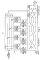
FIG. 1 provides a functional view, at a particular point in time, of a joint decoder/DFE embodying the principles of the present invention; -
FIG. 2 is a state transition diagram illustratively used in the decoder/DFE ofFIG. 1 vis-a-vis coded signal points; -
FIG. 3 shows the joint decoder/DFE ofFIG. 1 at a subsequent point in time; -
FIG. 4 is a state transition diagram illustratively used in the decoder/DFE vis-a-vis uncoded signal points; -
FIG. 5 is a combined block diagram/functional description view of the decoder/DFE ofFIGS. 1 and3 tailored for specific coded modulation; -
FIG. 6 is a state transition diagram illustratively used in the just mentioned specific coded modulation vis-a-vis coded signal points; -
FIG. 7 is a state transition diagram used in the just mentioned specific coded modulation vis-a-vis uncoded signal points; and -
FIG. 8 is similar toFIG. 5 but modified so as to implement my path-oriented, as opposed to state-oriented, approach to selecting surviving paths. - The decoder/DFE of
FIG. 1 is illustratively part of a receiving modem in which a signal xn, representing a transmitted signal point, is generated for the nth of a succession of signaling intervals. Signal xn was illustratively generated within the modem using conventional front-end steps such as sampling of an incoming line signal received from a telephone channel, demodulation and possibly feedforward equalization. Four replicas of xn are formed and a respective estimated intersymbol interference, or ISI, component is subtracted from each replica by a respective one ofadders 10, to produce equalizedsignals 

decision feedback equalizers 20, as described below. - The transmitted signal points represented by the xn's were generated in a transmit modem which used illustratively a probabilistic trellis coded modulation scheme of the type disclosed in
US Patent Nos. 6,157,678 andUS Patent No.5 953 376 . For purposes of illustration herein, it is assumed that the transmitter uses a four-state code which is why four replicas of xn are formed, as will become apparent as this description continues. In particular embodiments, however, other codes may be preferred, such as the 64-state code shown in those patent applications. - Viterbi
decoder 30 of the decoder/DFE receives the equalizedsignals 

decoder 30 as to the value of a particular xn is delayed by, in this example, 8 signaling intervals, this corresponding to the so-called decoding depth of the Viterbi decoder. The decoding depth of 8 is used herein for purposes of illustration. In actual practice, the decoding depth depends on the code that is being used and will typically be greater than 8. - The representation of Viterbi
decoder 30 inFIG. 1 includes a representation of the so-called trellis-made up of concatentations of the trellis code's state transition diagram, as described below-and further shows the so-called surviving paths extending through the trellis, each surviving path being associated with, and terminating on, one of the four states of the code, those states being denominated 0, 1, 2 and 3. As is well known, the coder in the transmit modem proceeds through a sequence of states which, in turn, defines a unique sequence of signal point subsets of a signal constellation. The coder output is a sequence of signal points each selected from a respective subset of the subset sequence thus defined. The task of the Viterbi decoder is to determine what the most likely sequence of signal points actually was, and central to that task is to determine the most likely sequence of transmitted signal points leading into each state of the code at any point in time. These are the aforementioned surviving paths, and the signal points along each path constitute a sequence of tentative signal point decisions. A metric is maintained for each surviving path, and, as described below, the current equalizedsignals 

path 8 signaling intervals earlier is taken as the final signal point decision. - Each of
DFEs 20 is associated with a particular one of the code states o, 1, 2 and 3. In particular, each DFE generates its respective ISI estimate as a function of the tentative signal point decisions which lie along the surviving path leading to the code state associated with that DFE. At this time, the ensemble of tentative signal point decisions along each newly determined surviving path are applied to the associated DFE in preparation for the generation of next set of ISI estimates to be applied toadders 10. In particular, as is well known, a DFE forms its ISI estimate by forming a combination (illustratively a linear combination) of the decisions that have been input to it using an ensemble of coefficients whose values may be adaptively updated. Thus it will be seen that each of the equalizedsignals 

- The process by which, as mentioned above, the current equalized
signals 

unit 31 within Viterbidecoder 30. Reference may be made toFIG. 2 . Associated with the code in question is a so-called state transition diagram which defines, for each current code state, which next state or states the coder is allowed to transition to. Thus, as shown by the solid and dashed lines within updatingunit 31, the code can transition fromcurrent state 0 to eithernext state 0 ornext state 1; fromcurrent state 1 to eithernext state 2 ornext state 3; fromcurrent state 2 to eithernext state 0 ornext state 1 ; and fromcurrent state 3 to eithernext state 2 ornext state 3. Each such transition is associated with one of the aforementioned constellation subsets, meaning that when the encoder transitions from a particular current state to one of the allowed next states, a signal point will be output by the transmitter which is taken from the subset associated with that state transition. A so-called branch metric is calculated for each of the (in this case) eight current-to-next-state transitions defined by the state transition diagram. The branch metric for each transition is given by the squared Euclidean distance between one of the equalizedsignals 

FIG. 2 illustrative values of the eight branch metrics are 0.4, 0.6, 0.3, 0.5, 0.5, 0.2, 0.2 and 0.1. The particular one of the equalized signals

signal 
current state 0 andnext states 
current state 1 andnext states 
current state 2 andnext states 
current state 3 andnext states next state 0 fromcurrent states next state 0. The branches shown in solid line within updatingunit 31 are the branches of the new surviving paths. (As is well known, normalization or other techniques may be used at this point to prevent the values of the path metrics from becoming so large as to possibly cause register overflow. However, the new path metrics shown inFIG. 2 are the pre-normalized values.) - At this point the very best surviving path is that leading into
state 0, it being the path with the smallest new path metric. The aforementioned final decision P̂n-8 is now output, it being the signal point on that very best surviving path from 8 signaling intervals earlier. - The preceding discussion has proceeded on the tacit assumption that each successive transmitted signal point is generated upon the occurrence of an advance in the state of the transmit encoder. However, in some applications this may not be the case, such as in the probabilistic TCM technique disclosed in my aforementioned co-pending patent applications. That is, a signal point may be transmitted without the transmit encoder state advancing. In the embodiments disclosed in those patent applications, such signal points are selected from an uncoded "outer" sub-constellation and are thus referred to herein as "uncoded signal points."
- The present invention is directed to a joint decoder/DFE which is designed to provide accurate ISI estimates in such an environment, and in accordance with the invention, ISI estimates for the uncoded signal points are generated in response to tentative decisions as to the coded signal points as formed by the Viterbi decoder.
- In particular embodiments of the invention, the signal points along the very best surviving path within the Viterbi decoder can be used as the past decisions input to a DFE used to form the ISI estimate for one of the uncoded signal points and an immediate final decision as to the uncoded signal point can be made. That decision would also be applied to whatever DFEs are employed in the system (such as the per-state DFEs mentioned above) and used over a number of subsequent signaling intervals to represent the value of the uncoded signal point in question.
- A more powerful, and preferred, implementation of the invention, however, is as shown in
FIG. 3 . In this implementation we do not form an immediate final decision as to the uncoded signal points but, rather, a tentative decision associated with each Viterbi decoder state using an ISI estimate provided from a DFE associated with that state. Each uncoded signal point tentative decision is used to extend the surviving path for the associated state and, in preferred embodiments, to also update its path metric. - This approach is illustratively implemented by the decoder/DFE structure of
FIG. 3 in the (n + 1)st signal interval. That is, it is assumed that the transmitted signal point in the (n +1)st signaling interval was one of the uncoded signal points.FIG. 3 is similar toFIG. 1 , except that since the received signal xn+1 represents an uncoded signal point, the state transition diagram used in updatingunit 31 is that shown inFIG. 4 . In particular, since the transmit coder state does not advance when an uncoded signal point is generated, the state transition diagram used by updatingunit 31 for uncoded signal points simply comprises four parallel branches, each extending from the current state to the same next state, i.e.,current state 0 tonext state 0,current state 1 tonext state 1, and so forth. As described in further detail hereinbelow, a decision is made as soon as each signal is received as to whether it represents a coded or uncoded signal point. The value of a one-bit control signal C indicates the result of that decision-C = 0(1) for a coded (uncoded) signal point C is used by updatingunit 31 to determine which state transition diagram is to be used-that ofFIG. 2 for coded signal points or that ofFIG. 4 for uncoded signal points. Thus C = 1 for the illustrative (n+ 1)st signaling interval represented byFIG. 3 . - Once it is recognized that the state transition diagram of
FIG. 4 is to be used at this time for purposes of updating the path metrics and finding the surviving paths, the overall operation is essentially the same as before. Each one of equalized signals

FIG. 2 - are themselves updated to provide new updated path metrics 0.9, 0.7, 0.8 and 0.9. Since only one path extends into each new state, each new surviving path is simply an extended version of the surviving path previously extending into that state. Also as before, the very best surviving path is identified-now it is the path leading intostate 1—and a final decision P̂n-7 is output, it being the signal point along that very best surviving path from 7 signaling intervals earlier. -
FIG. 5 provides a combined block diagram/functional description view of the decoder/DFE ofFIGS. 1 and 3 tailored for probablistic trellis-coded modulation of the type described in the above-cited patent applications. As such, the coded signal points are the signal points of the so-called inner sub-constellation of the overall signal constellation and the uncoded signal points are the signal points of the so-called outer sub-constellation of the overall signal constellation. Illustratively the code used is that implemented by the coder shown inFIG. 5 ofUS Patent No. 6 157 678 . The state transition diagram for that code is shown in the presentFIG. 6 , in which the branches are labeled with their associated innersub-constellation subsets FIG. 6 ofUS Patent No. 6 157 678 and the constellation is that shown in Appendix II thereof. - Looking then at
FIG. 5 , the received signal xn is processed atblock 51 to produce an equalized signal associated with each state of the code. As indicated in the FIG., the functionality of this block is that for each state, i, of the code, an equalized signal
- A signal indicative of whether the received signal represents a coded, inner sub-constellation, signal point or an uncoded, outer sub-constellation signal point is provided by
sub-constellation decision block 52 in a manner to be described. That signal corresponds to one-bit control signal C inFIGS. 1 and3 . - Assuming that the received signal has been determined to represent a coded, inner sub-constellation signal point, switch 53 is in the "down" position and the equalized signals are processed at
block 56. As indicated in the FIG., the functionality of this block is that for each state, i, of the code, we use
FIG. 6 . Then, atblock 57, the path metrics and the surviving paths are updated based on the same state transitiondiagram.Switch 58 will be in the "down" position at this time so that the flow proceeds to block 59 at which the very best surviving path is found and a final output decision is made. - If, on the other hand, the received signal has been determined to represent an uncoded, outer sub-constellation signal point, switch 53 is in the "up" position and the equalized signals are processed at
block 54. The functionality of this block is essentially similar to that ofblock 56 except that the state transition diagram is that shown inFIG. 7 . As with the state transition diagram ofFIG. 4 , the state transition diagram ofFIG. 7 comprises a single branch emanating from each current state and extending to the same next state. Each branch is associated with the entire outer sub-constellation. Thus, as indicated in the FIG., the functionality of this block is that for each state, i, of the code, we use
block 55, the path metric is updated and the surviving path is extended, as noted earler.Switch 58 will be in the "up" position at this time so that the flow proceeds to block 59 at which, as before, the very best surviving path is found and a final output decision is made. - A decision as to whether signal xn represents an inner or outer sub-constellation signal point would be most accurately made if one were to wait for the Viterbi decoder to provide a final decision as to that signal. However, that decision must be made at
sub-constellation decision block 52 soon as the signal is received. One can, however, use at least a portion of what it has already "learned" by the Viterbi decoder to aid in making that decision. In particular, as indicated in the FIG., a combiningstep 62 and a decisionfeedback equalization block 61 are used to form an equalized signal
block 61 being the tentative past decisions from the very best surviving path of the Viterbi decoder. Based on whether signal
subconstellation decision block 52 makes the inner or outer subconstellation decision. Since the ISI estimate is based on an assumed sequence of past signal points that may turn out to be not wholly correct, and since the decision as to whether the received signal is from the inner or outer sub-constellation is crucial to the performance of the overall system, it may be desired to provide some additional protection against making an error as to the sub-constellation. To this end, the constellation may be designed in such a way that the distance between its inner and outer sub-constellations is greater than would be otherwise dictated by other design criteria, e.g., greater than the effective minimum distance of the overall modulation scheme. Such a constellation is shown in Appendix I hereof, this constellation being very similar to that shown in Appendix II ofUS Patent No. 6,157,678 except that the distance between the inner and outer sub-constellations has been increased from 16 to 32. - In applications where bit robbing (as described in
US Patent No. 6,157,678 ) may occur, the constellation shown in Appendix m ofUS Patent No.6,157,678 may be used for the bit-robbed signaling intervals. In the context ofFIG. 5 hereof, a bit robbing indicator indicating the occurrence of a bit-robbed signaling interval would be applied atblocks US Patent No. 6,157,678 . - A further consideration relative to bit robbing is as follows: On the one hand, although a transmitted signal point can be received as another signal point due to bit robbing, both of those signal points map back into the same transmitted bit pattern so from that standpoint there is no problem, as discussed in
US Patent No. 6,157,678 . A potential problem arises, however, in that the decision as to the amplitude of the signal point is fed back to the DFE and it is possible that, due to noise and impairments between the receiving central office and the receiving modem, the signal point that was transmitted from the central office to the receiving modem may become so displaced that an incorrect decision is made in the receiving modem as to which of the two signal points was sent. The presence of this incorrect decision in the DFE will have a negative effect on the accuracy of the decoding process. - There are at least two ways to deal with this situation. One of them is to design the constellation in such a way that the distance between each pair of signal points that become one another due to bit robbing is at least the same as the effective minimum distance of the overall modulation scheme. By following this approach, one would ensure that any errors that occur in making decisions between the points in the same pair will not become the dominating errors in terms of the overall performance. The constellation shown in Appendix III, which could be used for the bit-robbed intervals, follows this approach. It may be observed, first of all, that the distance between each pair of points is at least 16, which is greater than the effective minimum distance "15" of the overall modulation scheme using the constellation of Appendix I for the non-bit robbed intervals. It may also be observed that the constellation of Appendix III is comprised solely of an outer sub-constellation whose smallest magnitude signal points are +/- 247.5. No signal points of smaller amplitude can be used because below the magnitude of 247.5, the distance between each pair of signal points is less than 15, thereby violating the desired design constraint. Moreover, since the minimum distance of 16 between different pairs of signal points of the constellation of Appendix III is already greater than the effective minimum distance of the overall modulation scheme, there would be no benefit to using coding to that constellation. It may be noted that the number of signal point pairs in this constellation is 30. As a consequence, this approach will support one less bit during the bit-robbed intervals than for the case of Appendix II. The choice between the use of the constellations of Appendices II and III will be made based on whether one is willing to endure the lower level of error rate performance provided by the constellation of Appendix II in order to have a higher bandwidth efficiency.
- The other approach is to design the constellation in such a way that the distance between each pair of points that become one another due to bit robbing is much smaller than the effective minimum distance of the overall modulation scheme, so that an error made in the receiver as to which one was transmitted will have a negligible effect on the decoder/DFE performance. In fact, one can use both of these approaches together, for example, having an inner, coded sub-constellation wherein each pair of signal points are very close together and an uncoded outer sub-constellation wherein each pair of signal points are very far apart, as just described.
- The above-described methodology used in the Viterbi decoder to select surviving paths follows a conventional, state-oriented, approach wherein, as will be recalled, the path having the smallest path metric among all paths coming into a given state is retained as a surviving path. This approach is indeed the most desirable approach when dealing with Gaussian channels.
- I have discovered, however, an alternative approach that is more advantageous for, for example, channels engendering a significant amount of intersymbol interference. In accordance with that approach, referred to herein as a "path-oriented" approach-the paths that are retained as the surviving paths are some number, M, of the paths which have the smallest path metrics, even if two or more of those paths may come into a given state. I have discovered that this path-oriented approach will achieve substantially the same (or only negligibly worse) level of performance as the state-oriented approach with a much reduced level of decoder complexity. For example, using a 64-state code, one can use M = 16-that is, retaining only the 16 best paths-and achieve essentially the same performance as the much more complex state-oriented approach in which 64 paths-one for each state-are retained. Moreover, in at least one case, I have observed that the simpler path-oriented approach can even outperform the state-oriented approach.
- It is known that in order to reduce decoder complexity one can use a reduced-state state-oriented approach in which the surviving paths leading into only a reduced number of states are retained, those being the states having the smaller path metrics. For a given code, the complexity of a reduced state scheme which retains the paths leading into M states is comparable to the complexity of my path-oriented approach retaining the M best paths. However, as between two such more-or-less equally complex approaches, it appears that the performance of the path-oriented approach will almost always be at least as good and, in some cases, will be much better.
-
FIG. 8 shows the implementation of my path-oriented approach for joint decoder/DFE in the present context of probablistic TCM. More particularly, various elements shown inFIG. 8 correspond, either exactly, or with modifications, to those shown inFIG. 5 . Those that correspond exactly bear the same reference numeral, whereasblocks FIG. 8 withblocks - In blocks 851, 854 and 856 the calculations that are carried out vis-a-vis the equalized signal

blocks 855 and 857 a new set of M best surviving paths are identified, along with their associated path metrics, rather than, as inFIG. 5 , identifying an updated surviving path, and its associated metric, for each state. - The foregoing is merely illustrative. Thus, for example, it will be appreciated by those skilled in the art that the block diagrams herein represent conceptual views of illustrative circuitry embodying the principles of the invention. The functions of the various elements shown in the FIGS. would, in preferred embodiments, be implemented by one or more programmed processors, digital signal processing (DSP) chips, or the like rather than individual hardware elements. Similarly, the switches shown in the FIGS. are conceptual only. Their function would typically be carried out through the operation of program logic.
- In the claims hereof any element expressed as a means for performing a specified function is intended to encompass any way of performing that function including, for example, a) a combination of circuit elements which performs that function or b) software in any form (including, therefore, firmware, microcode or the like) combined with appropriate circuitry for executing that software to perform the function. The invention is defined by such claims resides in the fact that the functionalities provided by the various recited means are combined and brought together in the manner which the claims call for. Applicant thus regards any means which can provide those functionalities as equivalent as those shown herein.
- It will be appreciated by those skilled in the art that they will be able devise various arrangements which, although not explicitly shown or described herein, embody the principles of the invention and thus are within its scope. Appendix I
I8 I7 I6 I5 I4 I3 I2 I1 or X1 X0 Amplitude of Signal Point 1 1 0 0 0 0 0 0 - 1,487.5 1 1 0 0 0 0 0 1 - 1,423.5 1 1 0 0 0 1 0 1 - 1,359.5 1 1 0 0 0 1 0 0 - 1,295.5 1 0 1 0 0 1 0 0 - 1,231.5 1 0 1 0 0 1 0 1 - 1,167.5 1 0 1 0 0 0 0 1 - 1,103.5 1 0 1 0 0 0 0 0 - 1,039.5 1 0 0 0 0 0 0 0 - 991.5 1 0 0 0 0 0 0 1 - 959.5 1 0 0 0 0 1 0 1 - 927.5 1 0 0 0 0 1 0 0 - 895.5 0 1 0 0 0 1 0 0 - 863.5 0 1 0 0 0 1 0 1 - 831.5 0 1 0 0 0 0 0 1 - 799.5 0 1 0 0 0 0 0 0 - 767.5 Positive Portion of Uncoded 76-PAM 0 1 0 0 1 0 0 0 - 735.5 Outer Subconstellation 0 1 0 0 1 0 0 1 - 703.5 0 1 0 0 1 1 0 1 - 671.5 0 1 0 0 1 1 0 0 - 639.5 0 1 0 1 1 1 0 0 - 607.5 0 1 0 1 1 1 0 1 - 575.5 0 1 0 1 1 0 0 1 - 543.5 0 1 0 1 1 0 0 0 - 511. 5 0 1 0 1 0 0 0 0 - 487.5 0 1 0 1 0 0 0 1 - 471.5 0 1 0 1 0 1 0 1 - 455.5 0 1 0 1 0 1 0 0 - 439.5 0 0 1 1 0 1 0 0 - 423.5 0 0 1 1 0 1 0 1 - 407.5 0 0 1 1 0 0 0 1 - 391.5 0 0 1 1 0 0 0 0 - 375.5 0 0 1 1 1 0 0 0 - 359.5 0 0 1 1 1 0 0 1 - 343.5 0 0 1 1 1 1 0 1 - 327.5 0 0 1 1 1 1 0 0 - 311.5 0 0 1 0 1 1 0 0 - 295.5 0 0 1 0 1 1 0 1 - 279.5 - - - - - - - - - - - - - - - - - - - - - - - - - - - - - - - - - - - - - - - - - - - 263.5 - - - - - - - - - - - - - 0 0 1 0 1 0 0 1 1 247.5 0 0 1 0 1 0 0 1 0 235.5 0 0 1 0 1 0 0 0 1 227.5 0 0 1 0 1 0 0 0 0 219.5 0 0 1 0 0 0 0 1 1 211.5 0 0 1 0 0 0 0 1 0 203.5 0 0 1 0 0 0 0 0 1 195.5 0 0 1 0 0 0 0 0 0 187.5 0 0 1 0 0 1 0 1 1 179.5 0 0 1 0 0 1 0 1 0 171.5 0 0 1 0 0 1 0 0 1 163.5 0 0 1 0 0 1 0 0 0 155.5 0 0 0 0 0 1 0 1 1 147.5 0 0 0 0 0 1 0 1 0 139.5 0 0 0 0 0 1 0 0 1 131.5 0 0 0 0 0 1 0 0 0 123.5 0 0 0 0 0 0 0 1 1 115.5 0 0 0 0 0 0 0 1 0 109.5 0 0 0 0 0 0 0 0 1 105.5 0 0 0 0 0 0 0 0 0 101.5 0 0 0 0 1 0 0 1 1 97.5 0 0 0 0 1 0 0 1 0 93.5 0 0 0 0 1 0 0 0 1 89.5 0 0 0 0 1 0 0 0 0 85.5 0 0 0 0 1 1 0 1 1 81.5 0 0 0 0 1 1 0 1 0 77.5 0 0 0 0 1 1 0 0 1 73.5 0 0 0 0 1 1 0 0 0 69.5 0 0 0 1 1 1 0 1 1 65.5 0 0 0 1 1 1 0 1 0 61.5 0 0 0 1 1 1 0 0 1 57.5 0 0 0 1 1 1 0 0 0 53.5 0 0 0 1 1 0 0 1 1 46.5 0 0 0 1 1 0 0 1 0 42.5 0 0 0 1 1 0 0 0 1 38.5 0 0 0 1 1 0 0 0 0 34.5 0 0 0 1 0 0 0 1 1 30.5 0 0 0 1 0 0 0 1 0 26.5 0 0 0 1 0 0 0 0 1 22.5 0 0 0 1 0 0 0 0 0 18.5 0 0 0 1 0 1 0 1 1 14.0 0 0 0 1 0 1 0 1 0 10.0 0 0 0 1 0 1 0 0 1 6.0 0 0 0 1 0 1 0 0 0 2.0 Coded 88-PAM 0 0 0 1 0 1 1 1 1 -2.0 Inner Subconstellation 0 0 0 1 0 1 1 1 0 -6.0 0 0 0 1 0 1 1 0 1 -10.0 0 0 0 1 0 1 1 0 0 -14.0 0 0 0 1 0 0 1 1 1 -18.5 0 0 0 1 0 0 1 1 0 -22.5 0 0 0 1 0 0 1 0 1 -26.5 0 0 0 1 0 0 1 0 0 -30.5 0 0 0 1 1 0 1 1 1 -34.5 0 0 0 1 1 0 1 1 0 -38.5 0 0 0 1 1 0 1 0 1 -42.5 0 0 0 1 1 0 1 0 0 -46.5 0 0 0 1 1 1 1 1 1 -53.5 0 0 0 1 1 1 1 1 0 -57.5 0 0 0 1 1 1 1 0 1 -61.5 0 0 0 1 1 1 1 0 0 -65.5 0 0 0 0 1 1 1 1 1 -69.5 0 0 0 0 1 1 1 1 0 -73.5 0 0 0 0 1 1 1 0 1 -77.5 0 0 0 0 1 1 1 0 0 -81.5 0 0 0 0 1 0 1 1 1 -85.5 0 0 0 0 1 0 1 1 0 -89.5 0 0 0 0 1 0 1 0 1 -93.5 0 0 0 0 1 0 1 0 0 -97.5 0 0 0 0 0 0 1 1 1 -101.5 0 0 0 0 0 0 1 1 0 -105.5 0 0 0 0 0 0 1 0 1 -109.5 0 0 0 0 0 0 0 1 0 0 -115.5 0 0 0 0 0 1 1 1 1 -123.5 0 0 0 0 0 1 1 1 0 -131.5 0 0 0 0 0 1 1 0 1 -139.5 0 0 0 0 0 1 1 0 0 -147.5 0 0 1 0 0 1 1 1 1 -155.5 0 0 1 0 0 1 1 1 0 -163.5 0 0 1 0 0 1 1 0 1 -171.5 0 0 1 0 0 1 1 0 0 -179.5 0 0 1 0 0 0 1 1 1 -187.5 0 0 1 0 0 0 1 1 0 -195.5 0 0 1 0 0 0 1 0 1 -203.5 0 0 1 0 0 0 1 0 0 -211.5 0 0 1 0 1 0 1 1 1 -219.5 0 0 1 0 1 0 1 1 0 -227.5 0 0 1 0 1 0 1 0 1 -235.5 0 0 1 0 1 0 1 0 0 -247.5 - - - - - - - - - - - - - - - - - - - - - - - - - - - - - - - - - - - - - - - - - - - - - - - - - - - - - -263.5 - - - - - - - - - - - - - 0 0 1 0 1 1 1 0 - -279.5 0 0 1 0 1 1 1 1 - -295.5 0 0 1 1 1 1 1 1 - -311.5 0 0 1 1 1 1 1 0 - -327.5 0 0 1 1 1 0 1 0 - -343.5 0 0 1 1 1 0 1 1 - -359.5 0 0 1 1 0 0 1 1 - -375.5 0 0 1 1 0 0 1 0 - -391.5 0 0 1 1 0 1 1 0 - -407.5 0 0 1 1 0 1 1 1 - -423.5 0 1 0 1 0 1 1 1 - -439.5 0 1 0 1 0 1 1 0 - -455. 5 0 1 0 1 0 0 1 0 - -471.5 0 1 0 1 0 0 1 1 - -487.5 0 1 0 1 1 0 1 1 - -511.5 0 1 0 1 1 0 1 0 - -543.5 0 1 0 1 1 1 1 0 - -575.5 0 1 0 1 1 1 1 1 - -607.5 0 1 0 0 1 1 1 1 - -639.5 0 1 0 0 1 1 1 0 - -671.5 0 1 0 0 1 0 1 0 - -703.5 Negative Portion of Uncoded 76-PAM 0 1 0 0 1 0 1 1 - -735.5 Outer Subconstellation 0 1 0 0 0 0 1 1 - -767.5 0 1 0 0 0 0 1 0 - -799.5 0 1 0 0 0 1 1 0 - -831.5 0 1 0 0 0 1 1 1 - -863.5 1 0 0 0 0 1 1 1 - -895.5 1 0 0 0 0 1 1 0 - -927.5 1 0 0 0 0 0 1* 0 - -959.5 1 0 0 0 0 0 1 1 - -991.5 1 0 1 0 0 0 1 1 - -1,039.5 1 0 1 0 0 0 1 0 - -1,103.5 1 0 1 0 0 1 1 0 - -1,167.5 1 0 1 0 0 1 1 1 - -1,231. 5 1 1 0 0 0 1 1 1 - -1,295.5 1 1 0 0 0 1 1 0 - -1,359.5 1 1 0 0 0 0 1 0 - -1,423.5 1 1 0 0 0 0 1 1 - -1,487.5 -
I8 I7 I6 I5 I4 I2 I1 or X1 - X0 Amplitude of Signal Point 1 1 0 0 0 0 1 - 1.487.5 1 1 0 0 0 0 1 - 1,423.5 x 1 1 0 0 0 0 0 - 1.359.5 1 1 0 0 0 0 0 - 1,295.5 x 1 0 1 0 0 0 0 - 1,231.5 1 0 1 0 0 0 0 - 1,167.5 x 1 0 1 0 0 0 1 - 1.103.5 1 0 1 0 0 0 1 - 1,039.5 x 1 0 0 0 0 0 1 - 991.5 1 0 0 0 0 0 1 - 959.5 x 1 0 0 0 0 0 0 - 927.5 1 0 0 0 0 0 0 - 895.5 x 0 1 0 0 0 0 0 - 863.5 0 1 0 0 0 0 0 - 831.5 x 0 1 0 0 0 0 1 - 799.5 0 1 0 0 0 0 1 - 767.5 x Positive Portion of encoded 38/76-PAM 0 1 0 0 1 0 1 - 735.5 Outer Subconstellation 0 1 0 0 1 0 1 - 703.5 x 0 1 0 0 1 0 0 - 671.5 0 1 0 0 1 0 0 - 639.5 x 0 1 0 1 1 0 0 - 607.5 0 1 0 1 1 0 0 - 575.5 x 0 1 0 1 1 0 1 - 543.5 0 1 0 1 1 0 1 - 511.5 x 0 1 0 1 0 0 1 - 487.5 0 1 0 1 0 0 1 - 471.5 x 0 1 0 1 0 0 0 - 455.5 0 1 0 1 0 0 0 - 439.5 x 0 0 1 1 0 0 0 - 423.5 0 0 1 1 0 0 0 - 407.5 x 0 0 1 1 0 0 1 - 391.5 0 0 1 1 0 0 1 - 375.5 x 0 0 1 1 1 0 1 - 359.5 0 0 1 1 1 0 1 - 343.5 x 0 0 1 1 1 0 0 - 327.5 0 0 1 1 1 0 0 - 311.5 x 0 0 1 0 1 1 0 - 295.5 0 0 1 0 1 1 0 - 279.5 x - - - - - - - - - - - - - - - - - - - - - - - - - - - - - - - - - - - - - - - - - - - 257.5 - - - - - - - - - - - - - 0 0 1 0 1 0 0 1 235.5 0 0 1 0 1 0 0 1 227.5 x 0 0 1 0 1 0 0 0 219.5 0 0 1 0 1 0 0 0 211.5 x 0 0 1 0 0 0 1* 1 203.5 0 0 1 0 0 0 1 1 195.5 x 0 0 1 0 0 0 1 0 187.5 0 0 1 0 0 0 1 0 179.5 x 0 0 1 0 0 0 0 1 171.5 0 0 1 0 0 0 0 1 163.5 x 0 0 1 0 0 0 0 0 155.5 0 0 1 0 0 0 0 0 147.5 x 0 0 0 0 0 0 1 1 139.5 0 0 0 0 0 0 1 1 131.5 x 0 0 0 0 0 0 1 0 123.5 0 0 0 0 0 0 1 0 115.5 x 0 0 0 0 0 0 0 1 109.5 0 0 0 0 0 0 0 1 105.5 x 0 0 0 0 0 0 0 0 101.5 0 0 0 0 0 0 0 0 97.5 x 0 0 0 0 1 0 1 1 93.5 0 0 0 0 1 0 1 1 89.5 x 0 0 0 0 1 0 1 0 85.5 0 0 0 0 1 0 1 0 81.5 x 0 0 0 0 1 0 0 1 77.5 0 0 0 0 1 0 0 1 73.5 x 0 0 0 0 1 0 0 0 69.5 0 0 0 0 1 0 0 0 65.5 x 0 0 0 1 1 0 1 1 61.5 0 0 0 1 1 0 1 1 57.5 x 0 0 0 1 1 0 1 0 46.5 0 0 0 1 1 0 1 0 44.5 x 0 0 0 1 1 0 0 1 38.5 0 0 0 1 1 0 0 1 36.5 x 0 0 0 1 1 0 0 0 30.5 0 0 0 1 1 0 0 0 28.5 x 0 0 0 1 0 0 1 1 22.5 0 0 0 1 0 0 1 1 20.5 x 0 0 0 1 0 0 1 0 15.0 0 0 0 0 1 0 0 1 0 14.0 x 0 0 0 1 0 0 0 1 9.0 0 0 0 1 0 0 0 1 8.0 x 0 0 0 1 0 0 0 0 3.0 0 0 0 1 0 0 0 0 2.0 x Coded 44/88-PAM 0 0 0 1 0 1 1 1 -2.0 x Inner Subconstellation 0 0 0 1 0 1 1 1 -3.0 0 0 0 1 0 1 1 0 -8.0 x 0 0 0 1 0 1 1 0 -9.0 0 0 0 1 0 1 0 1 14.0 x 0 0 0 1 0 1 0 1 -15.0 0 0 0 1 0 1 0 0 -20.5 x 0 0 0 1 0 1 0 0 -22.5 0 0 0 1 1 1 1 1 -28.5 x 0 0 0 1 1 1 1 1 -30.5 0 0 0 1 1 1 1 0 -36.5 x 0 0 0 1 1 1 1 0 -38.5 0 0 0 1 1 1 0 1 -44.5 x 0 0 0 1 1 1 0 1 -46.5 0 0 0 1 1 1 0 0 -57.5 x 0 0 0 1 1 1 0 0 -61.5 0 0 0 0 1 1 1 1 -65.5 x 0 0 0 0 1 1 1 1 -69.5 0 0 0 0 1 1 1 0 -73.5 x 0 0 0 0 1 1 1 0 -77.5 0 0 0 0 1 1 0 1 -81.5 x 0 0 0 0 1 1 0 1 -85.5 0 0 0 0 1 1 0 0 -89.5 x 0 0 0 0 1 1 0 0 -93.5 0 0 0 0 0 1 1 1 -97.5 x 0 0 0 0 0 1 1 1 -101.5 0 0 0 0 0 1 1 0 -105.5 x 0 0 0 0 0 1 1 0 -109.5 0 0 0 0 0 1 0 1 -115.5 x 0 0 0 0 0 1 0 1 -123.5 0 0 0 0 0 1 0 0 -131.5 x 0 0 0 0 0 1 0 0 -139.5 0 0 1 0 0 1 1 1 -147.5 x 0 0 1 0 0 1 1 1 -155.5 0 0 1 0 0 1 1 0 -163.5 x 0 0 1 0 0 1 1 0 -171.5 0 0 1 0 0 1 0 1 -179.5 x 0 0 1 0 0 1 0 1 -187.5 0 0 1 0 0 1 0 0 -195.5 x 0 0 1 0 0 1 0 0 -203.5 0 0 1 0 1 0 1 1 -211.5 x 0 0 1 0 1 0 1 1 -219.5 0 0 1 0 1 0 1 0 -227.5 x 0 0 1 0 1 0 1 0 -235.5 - - - - - - - - - - - - - - - - - - - - - - - - - - - - - - - - - - - - - - - - - - -257.5 - - - - - - - - - - - - - 0 0 1 0 1 1 1 - -279.5 x 0 0 1 0 1 1 1 - -295.5 0 0 1 1 1 1 1 - -311.5 x 0 0 1 1 1 1 1 - -327.5 0 0 1 1 1 1 0 - -343.5 x 0 0 1 1 1 1 0 - -359.5 0 0 1 1 0 1 0 - -375.5 x 0 0 1 1 0 1 0 - -391.5 0 0 1 1 0 1 1 - -407.5 x 0 0 1 1 0 1 1 - -423.5 0 1 0 1 0 1 1 - -439.5 x 0 1 0 1 0 1 1 - -455.5 0 1 0 1 0 1 0 - -471.5 x 0 1 0 1 0 1 0 - -487.5 0 1 0 1 1 1 0 - -511.5 x 0 1 0 1 1 1 0 - -543.5 0 1 0 1 1 1 1 - -575.5 x 0 1 0 1 1 1 1 - -607.5 0 1 0 0 1 1 1 - -639.5 x 0 1 0 0 1 1 1 - -671.5 0 1 0 0 1 1 0 - -703.5 x Negative Portion of Uncoded 38/76-PAM 0 1 0 0 1 1 0 - -735.5 Outer Subconctellation 0 1 0 0 0 1 0 - -767.5 x 0 1 0 0 0 1 0 - -799.5 0 1 0 0 0 1 1 - -831.5 x 0 1 0 0 0 1 1 - -863.5 1 0 0 0 0 1 1 - -895.5 x 1 0 0 0 0 1 1 - -927.5 1 0 0 0 0 1 0 - -959.5 x 1 0 0 0 0 1 0 - -991.5 1 0 1 0 0 1 0 - -1,039.5 x 1 0 1 0 0 1 0 - -1,103.5 1 0 1 0 0 1 1 - -1,167.5 x 1 0 1 0 0 1 1 - -1,231.5 1 1 0 0 0 1 1 - -1,295.5 x 1 1 0 0 0 1 1 - -1,359.5 1 1 0 0 0 1 0 - -1,423.5 x 1 1 0 0 0 1 0 - -1,487.5 -
I8 I7 I6 I5 I4 I1 Amplitude of Signal Point 1 1 0 0 0 0 927.5 1 1 0 0 0 0 895.5 x 1 0 1 0 0 0 863.5 1 0 1 0 0 0 831.5 x 1 0 0 0 0 0 799.5 1 0 0 0 0 0 767.5 x 0 1 0 0 0 0 735.5 0 1 0 0 0 0 703.5 x 0 1 0 0 1 0 671.5 0 1 0 0 1 0 639.5 x 0 1 0 1 1 0 607.5 0 1 0 1 1 0 575.5 x 0 1 0 1 0 0 543.5 0 1 0 1 0 0 511.5 x 0 0 0 1 0 0 487.5 0 0 0 1 0 0 471.5 x 0 0 0 1 1 0 455.5 0 0 0 1 1 0 439.5 x 0 0 0 0 1 0 423.5 0 0 0 0 1 0 407.5 x 0 0 0 0 0 0 391.5 0 0 0 0 0 0 375.5 x 0 0 1 0 0 0 359.5 0 0 1 0 0 0 343.5 x 0 0 1 0 1 0 327.5 0 0 1 0 1 0 311.5 x 0 0 1 1 1 0 295.5 0 0 1 1 1 0 279.5 x 0 0 1 1 0 0 263.5 0 0 1 1 0 0 247.5 x Uncoded 30/60-PAM 0 0 1 1 0 1 -247.5 x Constellation 0 0 1 1 0 1 -263.5 0 0 1 1 1 1 -279.5 x 0 0 1 1 1 1 -295.5 0 0 1 0 1 1 -311.5 x 0 0 1 0 1 1 -327.5 0 0 1 0 0 1 -343.5 x 0 0 1 0 0 1 -359.5 0 0 0 0 0 1 -375.5 x 0 0 0 0 0 1 -391.5 0 0 0 0 1 1 -407.5 x 0 0 0 0 1 1 -423.5 0 0 0 1 1 1 -439.5 x 0 0 0 1 1 1 -455.5 0 0 0 1 0 1 -471.5 x 0 0 0 1 0 1 -487.5 0 1 0 1 0 1 -511.5 x 0 1 0 1 0 1 -543.5 0 1 0 1 1 1 -575.5 x 0 1 0 1 1 1 -607.5 0 1 0 0 1 1 -639.5 x 0 1 0 0 1 1 -671.5 0 1 0 0 0 1 -703.5 x 0 1 0 0 0 1 -735.5 1 0 0 0 0 1 -767.5 x 1 0 0 0 0 1 -799.5 1 0 1 0 0 1 -831.5 x 1 0 1 0 0 1 -863.5 1 1 0 0 0 1 -895.5 x 1 1 0 0 0 1 -927.5
Claims (8)
- A maximum-likelihood decoding method for decoding a stream of transmitted signal points, a first plurality of said signal points having been generated using a predetermined code defined by a state transition diagram and a second plurality of said signal points having been generated not using said predetermined code, said method comprising the steps ofa) maintaining path metrics respectively associated with the states of said code,b) responsive to each received first plurality signal point, generating for each of said states, a branch metric associated with each next state to which each state is connected by a particular branch in the state transition diagram, and computing updated path metric for said next states based on path metrics of each connected state associated therewith and the generated branch metrics, and characterized by stepc) wherein, responsive to each received second plurality signal point, generating for each of said states a branch metric associated with a same next state, and computing an updated path metric for ones of said next states based on the updated path metrics of the associated same states of step b) and the generated branch metrics of said second plurality signal points, the said updated path metrics of the associated same states computed for the first plurality of signal points.
- The method of claim 1 wherein said first plurality signal points are representative of signal points of a first signal constellation, wherein each of the branches of said state transition diagram is associated with a respective subset of said first signal constellation and wherein in step b) each said branch metric is a function of the distance within said constellation between said each received first plurality signal point and the subset associated with each said particular branch.
- The method of claims 1 or 2 wherein said second plurality signal points are signal points of a second signal constellation, and wherein in step c) said branch metric is a function of the distance in said second signal constellation between said each received second plurality signal point and the nearest signal point of said second signal constellation.
- The method of claim 3 wherein said first and second signal constellations are respective sub-constellations of an overall signal constellation.
- The method of claim 3 comprising the further step of decoding values of said stream of signal points on response to the updated path metrics.
- The decoding method of claim 1 applied in a Viterbi decoder for decoding a stream of signal points corrupted by intersymbol interference, wherein the step of generating a branch metric responsive to received ones of the first plurality of signal points comprises the further step of:generating in response to each received signal point a plurality of equalized signal points, each equalized signal point being generated as a function of a respective estimate of the intersymbol interference component of said each received signal point, each estimate being a function of a respective present surviving path of said Viterbi decoder.
- The method of claim 6 wherein in the step of generating a plurality of equalized signal points, said each estimate is formed by a decision feedback equalizer which utilizes as its input decisions tentative decisions as the values of said stream of signal points which lie along the respective present surviving path.
- The decoding method of claim 1 wherein said first plurality of said signal points is generated using a predetermined trellis code.
Applications Claiming Priority (4)
| Application Number | Priority Date | Filing Date | Title |
|---|---|---|---|
| US5156197P | 1997-07-02 | 1997-07-02 | |
| US51561P | 1997-07-02 | ||
| US936649 | 1997-09-24 | ||
| US08/936,649 US5872817A (en) | 1997-07-02 | 1997-09-24 | Joint viterbi decoder and decision feedback equalizer |
Publications (3)
| Publication Number | Publication Date |
|---|---|
| EP0889612A2 EP0889612A2 (en) | 1999-01-07 |
| EP0889612A3 EP0889612A3 (en) | 2000-08-09 |
| EP0889612B1 true EP0889612B1 (en) | 2011-05-18 |
Family
ID=26729558
Family Applications (1)
| Application Number | Title | Priority Date | Filing Date |
|---|---|---|---|
| EP98304933A Expired - Lifetime EP0889612B1 (en) | 1997-07-02 | 1998-06-23 | Maximum-likelihood decoding method for coded modulation |
Country Status (4)
| Country | Link |
|---|---|
| US (1) | US5872817A (en) |
| EP (1) | EP0889612B1 (en) |
| JP (1) | JP3280622B2 (en) |
| KR (1) | KR100583897B1 (en) |
Cited By (2)
| Publication number | Priority date | Publication date | Assignee | Title |
|---|---|---|---|---|
| CN101202757B (en) * | 2002-08-01 | 2011-07-27 | 捷讯研究有限公司 | An always-on wireless internet protocol communication |
| CN1463525B (en) * | 2001-04-23 | 2012-12-05 | 皇家菲利浦电子有限公司 | Apparatus and method for decision feedback sequence estimation for reduction of error propagation in decision feedback equalizer |
Families Citing this family (66)
| Publication number | Priority date | Publication date | Assignee | Title |
|---|---|---|---|---|
| US6195386B1 (en) * | 1994-09-26 | 2001-02-27 | Texas Instruments Incorporated | Parallel decision feedback equalizer |
| US6151370A (en) * | 1998-02-12 | 2000-11-21 | Lucent Technologies Inc. | Path-oriented decoder for signal-dependent noise |
| EP0946024A1 (en) * | 1998-03-25 | 1999-09-29 | Ascom Systec AG | Decision feedback equalisation, in particular for data communication over powrr distribution networks |
| US6477200B1 (en) | 1998-11-09 | 2002-11-05 | Broadcom Corporation | Multi-pair gigabit ethernet transceiver |
| AU2022800A (en) * | 1998-11-09 | 2000-05-29 | Broadcom Corporation, Et Al. | Multi-pair gigabit ethernet transceiver |
| US6253345B1 (en) | 1998-11-13 | 2001-06-26 | Broadcom Corporation | System and method for trellis decoding in a multi-pair transceiver system |
| US6226332B1 (en) | 1998-11-13 | 2001-05-01 | Broadcom Corporation | Multi-pair transceiver decoder system with low computation slicer |
| US6252904B1 (en) * | 1998-11-13 | 2001-06-26 | Broadcom Corporation | High-speed decoder for a multi-pair gigabit transceiver |
| US6249544B1 (en) * | 1998-11-13 | 2001-06-19 | Broadcom Corporation | System and method for high-speed decoding and ISI compensation in a multi-pair transceiver system |
| US6421395B1 (en) * | 1999-02-09 | 2002-07-16 | Lucent Technologies Inc. | Termination of coded or uncoded modulation with path-oriented decoder |
| US6553518B1 (en) | 1999-03-08 | 2003-04-22 | International Business Machines Corporation | Severe error detectors, methods and computer program products that use constellation specific error event thresholds to detect severe error events during demodulation of a signal comprising symbols from a plurality of symbol constellations |
| US6661847B1 (en) | 1999-05-20 | 2003-12-09 | International Business Machines Corporation | Systems methods and computer program products for generating and optimizing signal constellations |
| US6570919B1 (en) * | 1999-07-30 | 2003-05-27 | Agere Systems Inc. | Iterative decoding of data packets employing decision feedback equalization |
| US6356586B1 (en) * | 1999-09-03 | 2002-03-12 | Lucent Technologies, Inc. | Methods and apparatus for parallel decision-feedback decoding in a communication system |
| US6327317B1 (en) * | 1999-09-10 | 2001-12-04 | Telefonaktiebolaget Lm Ericsson (Publ) | Combined equalization and decoding techniques |
| FR2798540B1 (en) * | 1999-09-13 | 2001-11-23 | France Telecom | METHOD OF JOINT DECODING AND EQUALIZATION OF A DIGITAL SIGNAL PROTECTED BY A CODE DEFINED BY A MESH |
| US6765955B1 (en) | 1999-10-29 | 2004-07-20 | International Business Machines Corporation | Methods, systems and computer program products establishing a communication configuration for a modem connection to compensate for echo noise |
| US6611563B1 (en) | 1999-10-29 | 2003-08-26 | International Business Machines Corporation | Systems, methods and computer program products for data mode refinement of modem constellation points |
| US6792004B1 (en) | 1999-10-29 | 2004-09-14 | International Business Machines Corporation | Systems, methods and computer program products for averaging learned levels in the presence of robbed-bit signaling based on proximity |
| US6826157B1 (en) | 1999-10-29 | 2004-11-30 | International Business Machines Corporation | Systems, methods, and computer program products for controlling data rate reductions in a communication device by using a plurality of filters to detect short-term bursts of errors and long-term sustainable errors |
| US6792040B1 (en) | 1999-10-29 | 2004-09-14 | International Business Machines Corporation | Modems having a dual power mode capability and methods of operating same |
| US6816545B1 (en) | 1999-10-29 | 2004-11-09 | International Business Machines Corporation | Systems, methods and computer program products for identifying digital impairments in modems based on clusters and/or skips in pulse code modulation signal levels |
| US6823004B1 (en) | 1999-10-29 | 2004-11-23 | International Business Machines Corporation | Methods, systems and computer program products for monitoring performance of a modem during a connection |
| US6754258B1 (en) | 1999-10-29 | 2004-06-22 | International Business Machines Corporation | Systems, methods and computer program products for averaging learned levels in the presence of digital impairments based on patterns |
| US6505222B1 (en) | 1999-10-29 | 2003-01-07 | International Business Machines Corporation | Systems methods and computer program products for controlling undesirable bias in an equalizer |
| US6650657B1 (en) | 1999-10-29 | 2003-11-18 | International Business Machines Corporation | Systems, methods and computer program products for identifying digital impairments in modem signals |
| US6823017B1 (en) | 1999-10-29 | 2004-11-23 | International Business Machines Corporation | Systems, methods and computer program products for filtering glitches from measured values in a sequence of code points |
| US6662322B1 (en) | 1999-10-29 | 2003-12-09 | International Business Machines Corporation | Systems, methods, and computer program products for controlling the error rate in a communication device by adjusting the distance between signal constellation points |
| US6754294B1 (en) | 1999-11-12 | 2004-06-22 | Cornell Research Foundation, Inc. | Dual equalizer for use in an receiver and method of operation |
| JP3515720B2 (en) | 1999-11-22 | 2004-04-05 | 松下電器産業株式会社 | Viterbi decoder |
| US6690739B1 (en) | 2000-01-14 | 2004-02-10 | Shou Yee Mui | Method for intersymbol interference compensation |
| EP1119145A1 (en) * | 2000-01-20 | 2001-07-25 | TELEFONAKTIEBOLAGET LM ERICSSON (publ) | Parallel decision feedback equalizer with adaptive thresholding based on noise estimates |
| US6600617B1 (en) | 2000-03-07 | 2003-07-29 | International Business Machines Corporation | Method and apparatus for adjusting digital filter taps based upon minimization of viterbi margin counts |
| US7177353B2 (en) * | 2000-03-10 | 2007-02-13 | Broadcom Corporation | Architecture for very high-speed decision feedback sequence estimation |
| US7106813B1 (en) * | 2000-03-16 | 2006-09-12 | Qualcomm, Incorporated | Method and apparatus for combined soft-decision based interference cancellation and decoding |
| EP1224783A2 (en) * | 2000-04-06 | 2002-07-24 | Lucent Technologies Inc. | Upstream data transmission |
| US6760385B1 (en) * | 2000-05-30 | 2004-07-06 | Adtran, Inc. | Universal parallel processing decoder |
| US7072392B2 (en) * | 2000-11-13 | 2006-07-04 | Micronas Semiconductors, Inc. | Equalizer for time domain signal processing |
| US6940557B2 (en) * | 2001-02-08 | 2005-09-06 | Micronas Semiconductors, Inc. | Adaptive interlace-to-progressive scan conversion algorithm |
| US7006566B2 (en) * | 2001-04-10 | 2006-02-28 | Koninklijke Philips Electronics N.V. | Two stage equalizer for trellis coded systems |
| US6823489B2 (en) * | 2001-04-23 | 2004-11-23 | Koninklijke Philips Electronics N.V. | Generation of decision feedback equalizer data using trellis decoder traceback output in an ATSC HDTV receiver |
| US6829297B2 (en) * | 2001-06-06 | 2004-12-07 | Micronas Semiconductors, Inc. | Adaptive equalizer having a variable step size influenced by output from a trellis decoder |
| US7190744B2 (en) * | 2001-06-07 | 2007-03-13 | Micronas Semiconductors, Inc. | Error generation for adaptive equalizer |
| US7418034B2 (en) * | 2001-06-19 | 2008-08-26 | Micronas Semiconductors. Inc. | Combined trellis decoder and decision feedback equalizer |
| WO2003012990A1 (en) | 2001-08-02 | 2003-02-13 | Aware, Inc. | Multicarrier modulation using frequency-domain equalizer and decision feedback |
| US7092438B2 (en) * | 2002-01-22 | 2006-08-15 | Siemens Communications, Inc. | Multilevel decision feedback equalizer |
| US20030206053A1 (en) * | 2002-04-04 | 2003-11-06 | Jingsong Xia | Carrier recovery for DTV receivers |
| US20030235259A1 (en) * | 2002-04-04 | 2003-12-25 | Jingsong Xia | System and method for symbol clock recovery |
| US6995617B2 (en) * | 2002-04-05 | 2006-02-07 | Micronas Semiconductors, Inc. | Data-directed frequency-and-phase lock loop |
| US7321642B2 (en) * | 2002-04-05 | 2008-01-22 | Micronas Semiconductors, Inc. | Synchronization symbol re-insertion for a decision feedback equalizer combined with a trellis decoder |
| US7376181B2 (en) * | 2002-04-05 | 2008-05-20 | Micronas Semiconductors, Inc. | Transposed structure for a decision feedback equalizer combined with a trellis decoder |
| US6980059B2 (en) * | 2002-04-05 | 2005-12-27 | Micronas Semiconductors, Inc. | Data directed frequency acquisition loop that synchronizes to a received signal by using the redundancy of the data in the frequency domain |
| US7272203B2 (en) * | 2002-04-05 | 2007-09-18 | Micronas Semiconductors, Inc. | Data-directed frequency-and-phase lock loop for decoding an offset-QAM modulated signal having a pilot |
| US20040096008A1 (en) * | 2002-08-01 | 2004-05-20 | Aware, Inc. | Multi-tap frequency domain equalization with decision feedback and trellis decoding |
| KR20040025516A (en) * | 2002-09-19 | 2004-03-24 | 삼성전자주식회사 | Channel Equalizer of Single carrier Receiver and a method equalizing thereof |
| CN100413295C (en) * | 2002-11-01 | 2008-08-20 | 上海奇普科技有限公司 | Self Adaptive equalizer for improving error signal production |
| US7003716B2 (en) * | 2002-12-26 | 2006-02-21 | Zydas Technology Corp. | Method and apparatus for using multi-dimensional trellis codes over multi-path channels |
| KR100539248B1 (en) | 2004-02-05 | 2005-12-27 | 삼성전자주식회사 | Decision-feedback equalizer and Method of feedback filter coefficient updating |
| US20090252202A1 (en) * | 2004-12-10 | 2009-10-08 | Koninklijke Philips Electronics, N.V. | Method and apparatus for enhanced decoding in multi-band ultra-wideband communications |
| CN100364257C (en) * | 2005-05-26 | 2008-01-23 | 上海奇普科技有限公司 | Time-domain adaptive aqualizer combined with NR code |
| US20070183489A1 (en) * | 2006-02-07 | 2007-08-09 | Samsung Electronics Co., Ltd. | Apparatus for decoding a signal and method thereof and a trellis coded modulation decoder and method thereof |
| US7912119B2 (en) * | 2007-08-23 | 2011-03-22 | Freescale Semiconductor, Inc. | Per-survivor based adaptive equalizer |
| JP5432288B2 (en) * | 2008-12-31 | 2014-03-05 | エスティー‐エリクソン、ソシエテ、アノニム | Process and receiver for interference cancellation of interfering base stations in a synchronous OFDM system |
| US20130028299A1 (en) * | 2011-07-26 | 2013-01-31 | Himax Media Solutions, Inc. | Adaptive ethernet transceiver with joint decision feedback equalizer and trellis decoder |
| US8938035B1 (en) | 2012-02-29 | 2015-01-20 | Marvell International Ltd. | System and method for transferring data over a two-pair communication system |
| CN102882817B (en) * | 2012-09-26 | 2017-07-14 | 华为技术有限公司 | Equalizing circuit, data transmission system and equalization methods |
Family Cites Families (6)
| Publication number | Priority date | Publication date | Assignee | Title |
|---|---|---|---|---|
| US617678A (en) | 1899-01-10 | emery | ||
| US5056117A (en) * | 1989-08-07 | 1991-10-08 | At&T Bell Laboratories | Decision feedback equalization with trellis coding |
| US5775855A (en) * | 1995-06-08 | 1998-07-07 | Valenite Inc. | Cutting insert and cutter for milling |
| JP3171772B2 (en) * | 1995-08-23 | 2001-06-04 | 沖電気工業株式会社 | Viterbi decoding method and Viterbi decoding device |
| US5953376A (en) | 1996-09-26 | 1999-09-14 | Lucent Technologies Inc. | Probabilistic trellis coded modulation with PCM-derived constellations |
| US6157678A (en) | 1996-12-18 | 2000-12-05 | Lucent Technologies Inc. | Probabilistic trellis/coded modulation with PCM-derived constellations |
-
1997
- 1997-09-24 US US08/936,649 patent/US5872817A/en not_active Expired - Lifetime
-
1998
- 1998-06-23 EP EP98304933A patent/EP0889612B1/en not_active Expired - Lifetime
- 1998-07-02 KR KR1019980027735A patent/KR100583897B1/en not_active IP Right Cessation
- 1998-07-02 JP JP18706998A patent/JP3280622B2/en not_active Expired - Fee Related
Cited By (2)
| Publication number | Priority date | Publication date | Assignee | Title |
|---|---|---|---|---|
| CN1463525B (en) * | 2001-04-23 | 2012-12-05 | 皇家菲利浦电子有限公司 | Apparatus and method for decision feedback sequence estimation for reduction of error propagation in decision feedback equalizer |
| CN101202757B (en) * | 2002-08-01 | 2011-07-27 | 捷讯研究有限公司 | An always-on wireless internet protocol communication |
Also Published As
| Publication number | Publication date |
|---|---|
| KR19990013737A (en) | 1999-02-25 |
| JP3280622B2 (en) | 2002-05-13 |
| US5872817A (en) | 1999-02-16 |
| EP0889612A2 (en) | 1999-01-07 |
| JPH11150481A (en) | 1999-06-02 |
| EP0889612A3 (en) | 2000-08-09 |
| KR100583897B1 (en) | 2006-11-30 |
Similar Documents
| Publication | Publication Date | Title |
|---|---|---|
| EP0889612B1 (en) | Maximum-likelihood decoding method for coded modulation | |
| US6178209B1 (en) | Method of estimating trellis encoded symbols utilizing simplified trellis decoding | |
| Kubo et al. | An adaptive maximum-likelihood sequence estimator for fast time-varying intersymbol interference channels | |
| US5550870A (en) | Viterbi processor | |
| US6356586B1 (en) | Methods and apparatus for parallel decision-feedback decoding in a communication system | |
| US7042938B2 (en) | Soft bit computation for a reduced state equalizer | |
| US6151370A (en) | Path-oriented decoder for signal-dependent noise | |
| US6269116B1 (en) | Method and arrangement for demodulating data symbols | |
| KR20000067966A (en) | Method and apparatus for detecting communication signals having unequal error protection | |
| US6233286B1 (en) | Path-oriented decoder using refined receiver trellis diagram | |
| KR100644952B1 (en) | Decision feedback equalizer for a digital signal receiving system | |
| EP1782543B1 (en) | Soft decision enhancement | |
| JPH08307283A (en) | Device and method for estimating maximum likelihood series | |
| EP0653715A2 (en) | Digital signal processor | |
| CA2276255A1 (en) | Apparatus, methods and computer program products for sequential maximum likelihood estimating communications signals using whitening path metrics | |
| CA2361374C (en) | Termination of coded or uncoded modulation with path-oriented decoder | |
| WO2002071710A1 (en) | Method for enhancing soft-value information | |
| JP4024364B2 (en) | Digital transmission system, digital signal receiver and digital signal receiving method | |
| JP2003506912A (en) | Method of generating reliability information for channel decoding in wireless receiver and corresponding wireless receiver | |
| Otnes et al. | On iterative equalization, estimation, and decoding | |
| JP2560893B2 (en) | Data signal receiver | |
| JP2894406B2 (en) | Maximum likelihood sequence estimator | |
| Kohno et al. | An automatic equalizer including a Viterbi decoder for trellis coded modulation system | |
| Lee et al. | The RSSE receiver with the channel estimator using the path history | |
| Singal | Mitigation of Inter-symbol Interference with Equalization and Convolution Coding |
Legal Events
| Date | Code | Title | Description |
|---|---|---|---|
| PUAI | Public reference made under article 153(3) epc to a published international application that has entered the european phase |
Free format text: ORIGINAL CODE: 0009012 |
|
| AK | Designated contracting states |
Kind code of ref document: A2 Designated state(s): DE FR GB |
|
| AX | Request for extension of the european patent |
Free format text: AL;LT;LV;MK;RO;SI |
|
| PUAL | Search report despatched |
Free format text: ORIGINAL CODE: 0009013 |
|
| AK | Designated contracting states |
Kind code of ref document: A3 Designated state(s): AT BE CH CY DE DK ES FI FR GB GR IE IT LI LU MC NL PT SE |
|
| AX | Request for extension of the european patent |
Free format text: AL;LT;LV;MK;RO;SI |
|
| RIC1 | Information provided on ipc code assigned before grant |
Free format text: 7H 04L 25/03 A, 7H 04L 27/34 B, 7H 04L 1/00 B |
|
| 17P | Request for examination filed |
Effective date: 20010125 |
|
| AKX | Designation fees paid |
Free format text: DE FR GB |
|
| 17Q | First examination report despatched |
Effective date: 20070425 |
|
| RAP3 | Party data changed (applicant data changed or rights of an application transferred) |
Owner name: LUCENT TECHNOLOGIES INC. |
|
| APBK | Appeal reference recorded |
Free format text: ORIGINAL CODE: EPIDOSNREFNE |
|
| APBN | Date of receipt of notice of appeal recorded |
Free format text: ORIGINAL CODE: EPIDOSNNOA2E |
|
| APBR | Date of receipt of statement of grounds of appeal recorded |
Free format text: ORIGINAL CODE: EPIDOSNNOA3E |
|
| APBV | Interlocutory revision of appeal recorded |
Free format text: ORIGINAL CODE: EPIDOSNIRAPE |
|
| GRAP | Despatch of communication of intention to grant a patent |
Free format text: ORIGINAL CODE: EPIDOSNIGR1 |
|
| RTI1 | Title (correction) |
Free format text: MAXIMUM-LIKELIHOOD DECODING METHOD FOR CODED MODULATION |
|
| GRAS | Grant fee paid |
Free format text: ORIGINAL CODE: EPIDOSNIGR3 |
|
| GRAA | (expected) grant |
Free format text: ORIGINAL CODE: 0009210 |
|
| REG | Reference to a national code |
Ref country code: GB Ref legal event code: FG4D |
|
| REG | Reference to a national code |
Ref country code: DE Ref legal event code: R096 Ref document number: 69842273 Country of ref document: DE Effective date: 20110630 |
|
| PLBE | No opposition filed within time limit |
Free format text: ORIGINAL CODE: 0009261 |
|
| STAA | Information on the status of an ep patent application or granted ep patent |
Free format text: STATUS: NO OPPOSITION FILED WITHIN TIME LIMIT |
|
| 26N | No opposition filed |
Effective date: 20120221 |
|
| REG | Reference to a national code |
Ref country code: DE Ref legal event code: R097 Ref document number: 69842273 Country of ref document: DE Effective date: 20120221 |
|
| PGFP | Annual fee paid to national office [announced via postgrant information from national office to epo] |
Ref country code: FR Payment date: 20140609 Year of fee payment: 17 |
|
| PGFP | Annual fee paid to national office [announced via postgrant information from national office to epo] |
Ref country code: GB Payment date: 20150527 Year of fee payment: 18 |
|
| REG | Reference to a national code |
Ref country code: FR Ref legal event code: ST Effective date: 20160229 |
|
| PG25 | Lapsed in a contracting state [announced via postgrant information from national office to epo] |
Ref country code: FR Free format text: LAPSE BECAUSE OF NON-PAYMENT OF DUE FEES Effective date: 20150630 |
|
| GBPC | Gb: european patent ceased through non-payment of renewal fee |
Effective date: 20160623 |
|
| PG25 | Lapsed in a contracting state [announced via postgrant information from national office to epo] |
Ref country code: GB Free format text: LAPSE BECAUSE OF NON-PAYMENT OF DUE FEES Effective date: 20160623 |
|
| PGFP | Annual fee paid to national office [announced via postgrant information from national office to epo] |
Ref country code: DE Payment date: 20170522 Year of fee payment: 20 |
|
| REG | Reference to a national code |
Ref country code: DE Ref legal event code: R071 Ref document number: 69842273 Country of ref document: DE |