EP0890143B1 - A window capacitive moisture sensor - Google Patents
A window capacitive moisture sensor Download PDFInfo
- Publication number
- EP0890143B1 EP0890143B1 EP97921120A EP97921120A EP0890143B1 EP 0890143 B1 EP0890143 B1 EP 0890143B1 EP 97921120 A EP97921120 A EP 97921120A EP 97921120 A EP97921120 A EP 97921120A EP 0890143 B1 EP0890143 B1 EP 0890143B1
- Authority
- EP
- European Patent Office
- Prior art keywords
- moisture
- dielectric
- capacitive
- sensor
- moisture sensor
- Prior art date
- Legal status (The legal status is an assumption and is not a legal conclusion. Google has not performed a legal analysis and makes no representation as to the accuracy of the status listed.)
- Expired - Lifetime
Links
Images


Classifications
-
- G—PHYSICS
- G05—CONTROLLING; REGULATING
- G05B—CONTROL OR REGULATING SYSTEMS IN GENERAL; FUNCTIONAL ELEMENTS OF SUCH SYSTEMS; MONITORING OR TESTING ARRANGEMENTS FOR SUCH SYSTEMS OR ELEMENTS
- G05B1/00—Comparing elements, i.e. elements for effecting comparison directly or indirectly between a desired value and existing or anticipated values
- G05B1/01—Comparing elements, i.e. elements for effecting comparison directly or indirectly between a desired value and existing or anticipated values electric
- G05B1/02—Comparing elements, i.e. elements for effecting comparison directly or indirectly between a desired value and existing or anticipated values electric for comparing analogue signals
-
- G—PHYSICS
- G05—CONTROLLING; REGULATING
- G05D—SYSTEMS FOR CONTROLLING OR REGULATING NON-ELECTRIC VARIABLES
- G05D22/00—Control of humidity
- G05D22/02—Control of humidity characterised by the use of electric means
-
- B—PERFORMING OPERATIONS; TRANSPORTING
- B60—VEHICLES IN GENERAL
- B60S—SERVICING, CLEANING, REPAIRING, SUPPORTING, LIFTING, OR MANOEUVRING OF VEHICLES, NOT OTHERWISE PROVIDED FOR
- B60S1/00—Cleaning of vehicles
- B60S1/02—Cleaning windscreens, windows or optical devices
- B60S1/023—Cleaning windscreens, windows or optical devices including defroster or demisting means
- B60S1/026—Cleaning windscreens, windows or optical devices including defroster or demisting means using electrical means
-
- B—PERFORMING OPERATIONS; TRANSPORTING
- B60—VEHICLES IN GENERAL
- B60S—SERVICING, CLEANING, REPAIRING, SUPPORTING, LIFTING, OR MANOEUVRING OF VEHICLES, NOT OTHERWISE PROVIDED FOR
- B60S1/00—Cleaning of vehicles
- B60S1/02—Cleaning windscreens, windows or optical devices
- B60S1/04—Wipers or the like, e.g. scrapers
- B60S1/06—Wipers or the like, e.g. scrapers characterised by the drive
- B60S1/08—Wipers or the like, e.g. scrapers characterised by the drive electrically driven
- B60S1/0818—Wipers or the like, e.g. scrapers characterised by the drive electrically driven including control systems responsive to external conditions, e.g. by detection of moisture, dirt or the like
- B60S1/0822—Wipers or the like, e.g. scrapers characterised by the drive electrically driven including control systems responsive to external conditions, e.g. by detection of moisture, dirt or the like characterized by the arrangement or type of detection means
- B60S1/0825—Capacitive rain sensor
- B60S1/0829—Oscillator-resonator rain sensor
-
- B—PERFORMING OPERATIONS; TRANSPORTING
- B60—VEHICLES IN GENERAL
- B60S—SERVICING, CLEANING, REPAIRING, SUPPORTING, LIFTING, OR MANOEUVRING OF VEHICLES, NOT OTHERWISE PROVIDED FOR
- B60S1/00—Cleaning of vehicles
- B60S1/02—Cleaning windscreens, windows or optical devices
- B60S1/56—Cleaning windscreens, windows or optical devices specially adapted for cleaning other parts or devices than front windows or windscreens
- B60S1/58—Cleaning windscreens, windows or optical devices specially adapted for cleaning other parts or devices than front windows or windscreens for rear windows
- B60S1/586—Cleaning windscreens, windows or optical devices specially adapted for cleaning other parts or devices than front windows or windscreens for rear windows including defroster or demisting means
-
- G—PHYSICS
- G01—MEASURING; TESTING
- G01N—INVESTIGATING OR ANALYSING MATERIALS BY DETERMINING THEIR CHEMICAL OR PHYSICAL PROPERTIES
- G01N27/00—Investigating or analysing materials by the use of electric, electrochemical, or magnetic means
- G01N27/02—Investigating or analysing materials by the use of electric, electrochemical, or magnetic means by investigating impedance
- G01N27/22—Investigating or analysing materials by the use of electric, electrochemical, or magnetic means by investigating impedance by investigating capacitance
- G01N27/223—Investigating or analysing materials by the use of electric, electrochemical, or magnetic means by investigating impedance by investigating capacitance for determining moisture content, e.g. humidity
- G01N27/225—Investigating or analysing materials by the use of electric, electrochemical, or magnetic means by investigating impedance by investigating capacitance for determining moisture content, e.g. humidity by using hygroscopic materials
-
- B—PERFORMING OPERATIONS; TRANSPORTING
- B60—VEHICLES IN GENERAL
- B60S—SERVICING, CLEANING, REPAIRING, SUPPORTING, LIFTING, OR MANOEUVRING OF VEHICLES, NOT OTHERWISE PROVIDED FOR
- B60S1/00—Cleaning of vehicles
- B60S1/02—Cleaning windscreens, windows or optical devices
- B60S1/04—Wipers or the like, e.g. scrapers
- B60S1/06—Wipers or the like, e.g. scrapers characterised by the drive
- B60S1/08—Wipers or the like, e.g. scrapers characterised by the drive electrically driven
- B60S1/0818—Wipers or the like, e.g. scrapers characterised by the drive electrically driven including control systems responsive to external conditions, e.g. by detection of moisture, dirt or the like
- B60S1/0822—Wipers or the like, e.g. scrapers characterised by the drive electrically driven including control systems responsive to external conditions, e.g. by detection of moisture, dirt or the like characterized by the arrangement or type of detection means
- B60S1/0874—Wipers or the like, e.g. scrapers characterised by the drive electrically driven including control systems responsive to external conditions, e.g. by detection of moisture, dirt or the like characterized by the arrangement or type of detection means characterized by the position of the sensor on the windshield
- B60S1/0877—Wipers or the like, e.g. scrapers characterised by the drive electrically driven including control systems responsive to external conditions, e.g. by detection of moisture, dirt or the like characterized by the arrangement or type of detection means characterized by the position of the sensor on the windshield at least part of the sensor being positioned between layers of the windshield
Definitions
- the present invention relates to automotive window moisture sensors and, more particularly, to a moisture sensor especially suitable for sensing moisture on the inner surface of automobile windows, and for automatic activation of window heaters.
- Automotive windshield moisture sensors have been introduced for automating the operation of windshield wipers.
- One such type of moisture sensor is based on electro-optical detection of raindrops by sensing changes in the total internal reflection of a light beam reflected off the front glass-air interface.
- a typical moisture sensor of this type is described in US Patent No. 4,859,867.
- the conductive electrodes be deposited between the glass laminates of the windshield.
- Typical moisture sensors of this type are described in US Patent No. 3,826,979, US Patent No. 4,703,237, in US Patent No. 4,827,198, in US Patent No. 4,613,802, and in US Patent No. 4,554,493.
- the dielectric glass layer that separates the sensing electrodes from the water droplets decreases the moisture signal to such an extent that the moisture signal is very small compared to parasitic signals that result from temperature effects and mechanical stresses in the glass. If these parasitic signals were constant, they would result in a fixed offset sensor output error. Since the dielectric constant of the glass is temperature dependent, for example, resulting in a varying offset error, the parasitic effects should be suppressed as much as possible.
- a final type of prior art capacitive moisture sensor is exemplified by that of WO97/37288. It uses a film of deposited polymer which interacts with moisture. This type of moisture sensor does not lend itself to use on the inside surface of windshields.
- this invention provides a capacitive moisture sensor comprising a pair of spaced electrodes for sensing moisture on a surface of a dielectric having two opposed surfaces, characterised in that the capacitive moisture sensor is substantially insensitive to the presence of moisture on the other unsensed surface of the dielectric, the capacitive moisture sensor comprising
- this invention provides an apparatus for sensing moisture on a surface of a dielectric having two opposed surfaces, in which the moisture sensing is insensitive to the presence of moisture on the other surface of the dielectric, characterised in that the surface to be sensed is an internal surface and the apparatus comprises
- the invention thus uses an automotive window-moisture capacitive sensor with sensing electrodes on the internal side of the window which is substantially insensitive to precipitation on the outside of the window.
- the sensor is intended for rear windows.
- the sensing-electrodes can be integrated with the window heater network, and can automatically activate the window heater network through a control circuit.
- the inner surface moisture sensor of the present invention can also be applied to other windows, such as front windshields, where it can automate defogging by means of hot air or electrical heating.
- the sensor of the present invention is applied to the window surface on which moisture is to be detected.
- the moisture signal level is orders of magnitude greater than in the buried electrode case.
- the time-varying, temperature-varying, stress-dependent parasitic coupling through the glass dielectric is insignificant.
- a charge amplifier may be conveniently located somewhere nearby on the edge of the window, where it will provide substantially no obscuration of the driver's held of view, and the rest of the signal processing electronics may be located in the same small module.
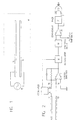
- FIG. 1 illustrates a schematic top view of a typical moisture sensor according to the present invention.
- the moisture sensor includes two electrodes, 12 and 13.
- Electrode 12 is excited by an alternating voltage source, 15, with a typical frequency of 10 kHz.
- the electrodes are coated on the window, 10.
- the electrodes may be made from any conductive material, such as vacuum deposited thin film, a silk-screen printed thick film, etc..
- Electrode, 13, the signal electrode collects the capacitively induced current as determined by the geometry of the electrodes and the medium around them, wherein the medium includes the glass window, 10, air, and, possibly, a moisture layer.
- FIG. 2 illustrates a typical block diagram of the moisture sensor system.
- Oscillator 15 generates two complementary alternating voltages, Q and Q'. Voltage Q is applied to the excitation electrode, 12, and voltage Q' is applied to a fixed capacitor, 16, whose value nominally equals the capacitance, C sensor , between electrodes 12 and 13 in their "dry" condition.
- the capacitance, C sensor increases due to the dielectric nature of water. In practice, the water may not be pure because of soil, salt spray, etc. and the impedance between the electrodes may include a resistive component which, combined with any DC component of the excitation voltage, could overload the amplifier. For this reason electrode 13 is coupled to the amplifier input through coupling capacitor 14.
- capacitor 16 nominally equals C sensor , the net current flowing into the virtual ground input of the charge-amplifier, 17, as well as the amplifier output voltage, are zero. In practice, due to manufacturing tolerances, there may be some fixed output signal even in the dry condition. This fixed output signal may be eliminated by a calibration during manufacturing.
- Demodulator 18 converts the alternating output signal of charge amplifier 17 into a unipolar voltage that is smoothed and converted into a DC voltage by low-pass filter 19.
- the operation of the demodulator is conventional and is based on switching its gain from -1 to +1 synchronously with excitation source 15.
- the output of low-pass filter 20, which depends on the thickness of the moisture layer, is compared by comparator 20, to a preset threshold voltage to generate a logic level output.
- the logic level output may serve as the command signal to the window heater, or defroster system.
- comparator 20 preferably includes a specific amount of hysteresis.
- the sensor system also includes a timer, 21, the purpose of which is explained below.
- the senor as shown in FIG. 1, would be sensitive to moisture on both sides of the glass window, 10, since rain drops on the second (external) side of the window will affect the sensor capacitance as well as moisture on the active side (internal to the vehicle).
- Such sensitivity is undesirable, but it was found that there is a way to control it, to make it insignificantly small. This is based on the fact that the lateral separation, d, between electrodes 12 and 13 affects both the desired sensitivity to moisture on the internal side of the window and the undesirable sensitivity to water on the external side.
- the sensitivity to moisture on the internal side of the window is proportional to the field intensity between the electrodes, i.e., it is roughly proportional to 1/d as illustrated in the cut-away view in FIG. 3A.
- the sensitivity to moisture on the external side of the window depends on fringing field lines at a distance, D, from the electrodes, which is roughly proportional to d/D.
- the density of these lines of force is further diminished by the shunting effect of the (dielectric) glass.
- the width of the electrodes is relatively unimportant in determining the sensitivity to moisture on the unsensed surface of the window.
- a shield electrode, 51 may be incorporated on a surface the internal laminate layer, 52, of laminated automobile window sandwich glass, 510, to provide complete insensitivity to moisture on the unsensed surface, 50, of the window.
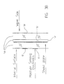
- FIG. 4 illustrates a typical integrated heater network and sensor, including a patterned heater element, 20, and two sensor electrodes, 12 and 13.
- the two sensor electrodes are parallel to the adjacent heater lines, and equally distant from the adjacent heater lines. The reason for this is that in the presence of moisture on the internal side of the window, the heater first evaporates the moisture near the heater lines, while the areas last to be dried are in the shape of lines parallel and between the heater lines. If the sensing electrodes are situated in this area they will sense the presence of the remaining moisture until the evaporation is complete. To assure complete evaporation, it is desirable that the heater remain on for a certain amount of time after comparator 20 switches to the low state. The low state indicates the absence of moisture.
- timer 21 which is activated by the transition of comparator 20 to the low state.
- OR-gate 22 provides a heating command with an extra duration that guarantees a complete drying.
- the extra duration is the time delay provided by the time-out of timer 20, providing a heater turn-off delay.
- the inner-surface window-moisture sensor of the present invention may be combined with other moisture sensors, to provide a complete moisture-sensing system.
- the inner surface moisture sensor of the present invention may also be used in conjunction with prior art moisture sensors, such as the optical moisture sensors described above.
- the sensor electronics may be modified as necessary to suit various applications.
Description
Claims (16)
- A capacitive moisture sensor comprising a pair of spaced electrodes for sensing moisture on a surface of a dielectric (10) having two opposed surfaces, characterised in that the capacitive moisture sensor is substantially insensitive to the presence of moisture on the other unsensed surface of the dielectric, the capacitive moisture sensor comprising(a) at least one pair of capacitive electrode plates (12,13) coated on the surface of the dielectric on which moisture is to be sensed, said at least one pair of capacitive electrode plates (12,13) including at least one pair of excitation and signal capacitive electrode plates;(b) electronic circuitry for substantially ignoring a resistive component of impedance between said electrode plates.
- A moisture sensor as in claim 1, including control means responsive to the lateral separation between said sensor electrodes to make the moisture sensor insensitive to moisture on the other unsensed side of the dielectric.
- A capacitive moisture sensor as in claim 1 or 2, having a sensitivity to moisture on the surface on which moisture is to be sensed, the dielectric (10) having a thickness, D, said excitation and signal capacitive electrode (12,13) plates being separated by a distance, d, thereby resulting in a fringing field on the other unsensed surface of the dielectric roughly proportional to d/D, and
there existing, as a result a ratio of said sensitivity to moisture on the surface of the dielectric on which moisture is to be sensed, to said sensitivity to moisture on the other unsensed surface of the dielectric, roughly proportional to D/d2. - A capacitive moisture sensor as in any preceding claim, having excitation (12) and signal (13) capacitive electrode plates, further comprising(a) an alternating excitation source (15) connected to the excitation capacitive electrode plate;(b) the signal electrode plate (13) being for collecting capacitively induced signal and being connected to an amplifier (17) which provides an amplified capacitively induced signal; and,(c) a synchronous demodulator (18) coupled to the signal electrode plate (13) for synchronously demodulating said amplified capacitively induced signal synchronously with said alternating excitation source (15).
- A capacitive moisture sensor as in claims 1 to 3, wherein said electronic circuitry for substantially ignoring a resistive component of impedance between said electrode plates includes a synchronous demodulator (18).
- A moisture sensor as in any preceding claim applied on the inside (52) of a window (10) as dielectric for automatic defogging.
- A moisture sensor as in any one of claims 1 to 5 applied on the inside (52) of a front or rear window (10) in a motor vehicle as dielectric for automating the operation defogging.
- A moisture sensor as in any preceding claim, wherein the dielectric is sandwich glass (510) having an internal laminate layer (52), said moisture sensor insensitive to moisture on the other unsensed side of the dielectric including an electrically conductive shield layer (51) on a surface of said internal laminate layer of said sandwich glass.
- The combination of a capacitive moisture sensor as in any of the preceding claims with an evaporating means (20), wherein the output from said moisture sensor acts to control said evaporating means.
- The combination of claim 9, where the sensor has capacitive electrodes (12,13) which have a lateral separation, d, the dielectric having a thickness D, and wherein control means for said lateral separation is operative to make the moisture sensor insensitive to moisture on the other unsensed side of the dielectric (10), by control of the ratio, D/d2
- The combination of claim 9 or 10, further comprising sensor electronics circuitry to activate said evaporating means (20) when moisture is sensed, said electronics circuitry including a turn-off delay to assure complete evaporation of moisture on the sensed surface.
- The combination of any one of claims 9 to 11, wherein said evaporating means (20) comprises a moisture heater grid, and wherein said moisture sensor capacitor plate and said heater are produced by simultaneous printing on conductive material.
- An apparatus for sensing moisture on a surface of a dielectric (10) having two opposed surfaces, in which the moisture sensing is insensitive to the presence of moisture on the other surface of the dielectric, characterised in that the surface to be sensed in an internal surface and the apparatus comprises(a) a moisture sensor including at least one pair of capacitive electrode plates including at least one pair of excitation (12) and signal capacitive (13) electrode plates coated on the moisture sensed surface of a dielectric; and(b) signal conditioning electronic circuitry for use with said moisture sensor which provides a logic output when moisture is present or said surface.
- A moisture sensing apparatus as in claim 13, wherein said moisture sensor is made insensitive to moisture on the other unsensed side of the dielectric by the setting of the lateral separation between said excitation (12) and signal capacitive (13) electrode plates.
- The apparatus of claim 13 or 14, wherein said signal conditioning circuitry includes a timer (21) providing additional heater on time to assure complete evaporation.
- The apparatus of any one of claims 13 to 15, wherein the dielectric is a sandwich glass (510) having an internal laminate layer (52), said moisture sensor including an electrically conductive shield layer (51) on a surface of said internal laminate layer of said sandwich glass.
Priority Applications (1)
| Application Number | Priority Date | Filing Date | Title |
|---|---|---|---|
| DE29724046U DE29724046U1 (en) | 1996-03-29 | 1997-03-27 | Capacitive window moisture sensor |
Applications Claiming Priority (3)
| Application Number | Priority Date | Filing Date | Title |
|---|---|---|---|
| US625473 | 1996-03-29 | ||
| US08/625,473 US5751071A (en) | 1996-03-29 | 1996-03-29 | Window capacitive moisture sensor |
| PCT/US1997/005807 WO1997037288A1 (en) | 1996-03-29 | 1997-03-27 | A window capacitive moisture sensor |
Publications (3)
| Publication Number | Publication Date |
|---|---|
| EP0890143A1 EP0890143A1 (en) | 1999-01-13 |
| EP0890143A4 EP0890143A4 (en) | 1999-06-30 |
| EP0890143B1 true EP0890143B1 (en) | 2001-12-19 |
Family
ID=24506256
Family Applications (1)
| Application Number | Title | Priority Date | Filing Date |
|---|---|---|---|
| EP97921120A Expired - Lifetime EP0890143B1 (en) | 1996-03-29 | 1997-03-27 | A window capacitive moisture sensor |
Country Status (6)
| Country | Link |
|---|---|
| US (1) | US5751071A (en) |
| EP (1) | EP0890143B1 (en) |
| JP (1) | JP3715324B2 (en) |
| KR (1) | KR100367193B1 (en) |
| AU (1) | AU2724697A (en) |
| WO (1) | WO1997037288A1 (en) |
Cited By (5)
| Publication number | Priority date | Publication date | Assignee | Title |
|---|---|---|---|---|
| US7204130B2 (en) | 2002-12-03 | 2007-04-17 | Ppg Industries Ohio, Inc. | Windshield moisture detector |
| US7263875B2 (en) | 2004-10-11 | 2007-09-04 | Ppg Industries Ohio, Inc. | Multi-layer windshield moisture detector |
| US7296461B2 (en) | 2002-12-03 | 2007-11-20 | Ppg Industries Ohio, Inc. | Temperature compensated windshield moisture detector |
| US9512661B2 (en) | 2013-03-19 | 2016-12-06 | Ford Global Technologies, Llc | Rain onset detection glazing auto-close |
| US9752370B2 (en) | 2015-07-13 | 2017-09-05 | Ford Global Technologies, Llc | Rain onset detection auto-close user interface |
Families Citing this family (18)
| Publication number | Priority date | Publication date | Assignee | Title |
|---|---|---|---|---|
| DE19723858A1 (en) * | 1997-06-06 | 1998-12-10 | Bosch Gmbh Robert | Device for heating a pane |
| US6091065A (en) * | 1998-12-31 | 2000-07-18 | Libbey-Owens-Ford Co. | Moisture sensor with digital signal processing filtering |
| US6178075B1 (en) * | 1999-06-04 | 2001-01-23 | Visteon Global Technologies, Inc. | Electronic module with moisture protection |
| WO2001090732A2 (en) * | 2000-05-10 | 2001-11-29 | Matheson Tri-Gas, Inc. | Capacitive-impedance type humidity/moisture sensing apparatus and method |
| US20020039008A1 (en) | 2000-09-29 | 2002-04-04 | Siemens Automotive Corporation | Power closure sensor system and method |
| DE10152999C2 (en) * | 2001-10-26 | 2003-12-24 | Preh Elektro Feinmechanik | Sensor and sensor unit for the detection of a tendency to fog |
| US20050040151A1 (en) * | 2003-08-20 | 2005-02-24 | Robert Dyrdek | Heated side window glass |
| DE102005022908A1 (en) * | 2005-05-19 | 2006-11-23 | Hella Kgaa Hueck & Co. | Device for humidification detection for motor vehicles |
| DE102006032372A1 (en) * | 2005-07-19 | 2007-02-15 | Preh Gmbh | Capacitive rain sensor |
| US7551094B2 (en) | 2006-01-10 | 2009-06-23 | Guardian Industries Corp. | Rain sensor with fractal capacitor(s) |
| US7551095B2 (en) * | 2006-01-10 | 2009-06-23 | Guardian Industries Corp. | Rain sensor with selectively reconfigurable fractal based sensors/capacitors |
| US9371032B2 (en) | 2006-01-10 | 2016-06-21 | Guardian Industries Corp. | Moisture sensor and/or defogger with Bayesian improvements, and related methods |
| US9063067B1 (en) | 2010-11-17 | 2015-06-23 | Alvin P. Schmitt | Moisture sensing devices |
| GB2507060A (en) * | 2012-10-17 | 2014-04-23 | Nissan Motor Mfg Uk Ltd | Window assembly |
| DE102014201640A1 (en) * | 2014-01-30 | 2015-07-30 | BSH Hausgeräte GmbH | Temperature measurement on a surface heating for a household appliance |
| WO2016073679A1 (en) | 2014-11-05 | 2016-05-12 | Sears Brands, L.L.C. | Water sensors with multi-value outputs and associated systems and methods |
| US10274449B2 (en) * | 2016-10-17 | 2019-04-30 | Robert Bosch Gmbh | Capacitive moisture sensor system for a surveillance camera |
| US10466195B2 (en) * | 2017-03-14 | 2019-11-05 | Ford Global Technologies, Llc | Vehicle window having moisture sensor |
Family Cites Families (7)
| Publication number | Priority date | Publication date | Assignee | Title |
|---|---|---|---|---|
| FR2268425B1 (en) * | 1974-04-19 | 1977-10-14 | Saint Gobain | |
| US4196338A (en) * | 1974-04-29 | 1980-04-01 | Saint-Gobain Industries | Electrically heated vehicle window |
| DE3215802A1 (en) * | 1982-04-28 | 1983-11-03 | Bayerische Motoren Werke AG, 8000 München | SWITCHING ARRANGEMENT FOR A ELECTRICAL ADDITIONAL HEATING IN MOTOR VEHICLES |
| US4665351A (en) * | 1986-02-05 | 1987-05-12 | General Motors Corporation | Windshield wiper control system and a precipitation sensor therefor |
| US4805070A (en) * | 1987-10-22 | 1989-02-14 | Ppg Industries, Inc. | Capacitive coupled moisture sensor |
| JPH05505234A (en) * | 1989-08-29 | 1993-08-05 | エー ウント エー エレクトロニク ゲゼルシャフト エム ベー ハー | How to use swellable plastics and make capacitive humidity sensors |
| US5040411A (en) * | 1989-12-27 | 1991-08-20 | Ppg Industries, Inc. | Windshield moisture sensor |
-
1996
- 1996-03-29 US US08/625,473 patent/US5751071A/en not_active Expired - Lifetime
-
1997
- 1997-03-27 AU AU27246/97A patent/AU2724697A/en not_active Abandoned
- 1997-03-27 JP JP53561797A patent/JP3715324B2/en not_active Expired - Fee Related
- 1997-03-27 WO PCT/US1997/005807 patent/WO1997037288A1/en active IP Right Grant
- 1997-03-27 KR KR10-1998-0708144A patent/KR100367193B1/en not_active IP Right Cessation
- 1997-03-27 EP EP97921120A patent/EP0890143B1/en not_active Expired - Lifetime
Cited By (5)
| Publication number | Priority date | Publication date | Assignee | Title |
|---|---|---|---|---|
| US7204130B2 (en) | 2002-12-03 | 2007-04-17 | Ppg Industries Ohio, Inc. | Windshield moisture detector |
| US7296461B2 (en) | 2002-12-03 | 2007-11-20 | Ppg Industries Ohio, Inc. | Temperature compensated windshield moisture detector |
| US7263875B2 (en) | 2004-10-11 | 2007-09-04 | Ppg Industries Ohio, Inc. | Multi-layer windshield moisture detector |
| US9512661B2 (en) | 2013-03-19 | 2016-12-06 | Ford Global Technologies, Llc | Rain onset detection glazing auto-close |
| US9752370B2 (en) | 2015-07-13 | 2017-09-05 | Ford Global Technologies, Llc | Rain onset detection auto-close user interface |
Also Published As
| Publication number | Publication date |
|---|---|
| JP3715324B2 (en) | 2005-11-09 |
| EP0890143A1 (en) | 1999-01-13 |
| US5751071A (en) | 1998-05-12 |
| KR100367193B1 (en) | 2003-03-28 |
| WO1997037288A1 (en) | 1997-10-09 |
| EP0890143A4 (en) | 1999-06-30 |
| AU2724697A (en) | 1997-10-22 |
| KR20000005411A (en) | 2000-01-25 |
| JP2001515584A (en) | 2001-09-18 |
Similar Documents
| Publication | Publication Date | Title |
|---|---|---|
| EP0890143B1 (en) | A window capacitive moisture sensor | |
| EP0753438B1 (en) | A differential windshield capacitive moisture sensor | |
| US5801307A (en) | Differential windshield capacitive moisture sensors | |
| US6373263B1 (en) | Differential windshield capacitive rain sensor | |
| EP0444022B1 (en) | Capacitive coupled moisture sensor and its use | |
| US6094981A (en) | Capacitive rain sensor for windshield | |
| JP4334200B2 (en) | Sensor unit for detecting glass wetness | |
| US7296461B2 (en) | Temperature compensated windshield moisture detector | |
| AU2003293233B2 (en) | Moisture detection system and method of use thereof | |
| CA2631710C (en) | Rain sensor for detecting rain or other material on window of a vehicle or on other surface | |
| WO2006042248A1 (en) | Windshield moisture detector | |
| US7263875B2 (en) | Multi-layer windshield moisture detector | |
| EP1480858B1 (en) | Moisture detection system and method of use thereof | |
| JPH05264496A (en) | Raindrop sensor | |
| CA1310692C (en) | Capacitive coupled moisture sensor | |
| DE29724046U1 (en) | Capacitive window moisture sensor | |
| JP2519331B2 (en) | Wetness detection sensor | |
| JP2008195396A (en) | Moisture detection system and its use |
Legal Events
| Date | Code | Title | Description |
|---|---|---|---|
| PUAI | Public reference made under article 153(3) epc to a published international application that has entered the european phase |
Free format text: ORIGINAL CODE: 0009012 |
|
| 17P | Request for examination filed |
Effective date: 19981021 |
|
| AK | Designated contracting states |
Kind code of ref document: A1 Designated state(s): BE ES FR GB IT SE |
|
| RAP1 | Party data changed (applicant data changed or rights of an application transferred) |
Owner name: MILLENNIUM SENSORS LTD. |
|
| A4 | Supplementary search report drawn up and despatched |
Effective date: 19990514 |
|
| AK | Designated contracting states |
Kind code of ref document: A4 Designated state(s): BE ES FR GB IT SE |
|
| RIC1 | Information provided on ipc code assigned before grant |
Free format text: 6G 05B 1/02 A, 6G 05B 21/00 B, 6H 05B 1/02 B, 6G 01N 27/12 B |
|
| 17Q | First examination report despatched |
Effective date: 19991018 |
|
| GRAG | Despatch of communication of intention to grant |
Free format text: ORIGINAL CODE: EPIDOS AGRA |
|
| GRAG | Despatch of communication of intention to grant |
Free format text: ORIGINAL CODE: EPIDOS AGRA |
|
| GRAH | Despatch of communication of intention to grant a patent |
Free format text: ORIGINAL CODE: EPIDOS IGRA |
|
| GRAH | Despatch of communication of intention to grant a patent |
Free format text: ORIGINAL CODE: EPIDOS IGRA |
|
| GRAA | (expected) grant |
Free format text: ORIGINAL CODE: 0009210 |
|
| AK | Designated contracting states |
Kind code of ref document: B1 Designated state(s): BE ES FR GB IT SE |
|
| PG25 | Lapsed in a contracting state [announced via postgrant information from national office to epo] |
Ref country code: BE Free format text: LAPSE BECAUSE OF FAILURE TO SUBMIT A TRANSLATION OF THE DESCRIPTION OR TO PAY THE FEE WITHIN THE PRESCRIBED TIME-LIMIT Effective date: 20011219 |
|
| REG | Reference to a national code |
Ref country code: GB Ref legal event code: IF02 |
|
| PG25 | Lapsed in a contracting state [announced via postgrant information from national office to epo] |
Ref country code: SE Free format text: LAPSE BECAUSE OF FAILURE TO SUBMIT A TRANSLATION OF THE DESCRIPTION OR TO PAY THE FEE WITHIN THE PRESCRIBED TIME-LIMIT Effective date: 20020319 |
|
| ET | Fr: translation filed | ||
| PG25 | Lapsed in a contracting state [announced via postgrant information from national office to epo] |
Ref country code: ES Free format text: LAPSE BECAUSE OF FAILURE TO SUBMIT A TRANSLATION OF THE DESCRIPTION OR TO PAY THE FEE WITHIN THE PRESCRIBED TIME-LIMIT Effective date: 20020627 |
|
| PLBE | No opposition filed within time limit |
Free format text: ORIGINAL CODE: 0009261 |
|
| STAA | Information on the status of an ep patent application or granted ep patent |
Free format text: STATUS: NO OPPOSITION FILED WITHIN TIME LIMIT |
|
| 26N | No opposition filed | ||
| REG | Reference to a national code |
Ref country code: GB Ref legal event code: 732E |
|
| REG | Reference to a national code |
Ref country code: FR Ref legal event code: TP |
|
| PGFP | Annual fee paid to national office [announced via postgrant information from national office to epo] |
Ref country code: GB Payment date: 20070323 Year of fee payment: 11 |
|
| PGFP | Annual fee paid to national office [announced via postgrant information from national office to epo] |
Ref country code: IT Payment date: 20070505 Year of fee payment: 11 |
|
| PGFP | Annual fee paid to national office [announced via postgrant information from national office to epo] |
Ref country code: FR Payment date: 20070320 Year of fee payment: 11 |
|
| GBPC | Gb: european patent ceased through non-payment of renewal fee |
Effective date: 20080327 |
|
| REG | Reference to a national code |
Ref country code: FR Ref legal event code: ST Effective date: 20081125 |
|
| PG25 | Lapsed in a contracting state [announced via postgrant information from national office to epo] |
Ref country code: FR Free format text: LAPSE BECAUSE OF NON-PAYMENT OF DUE FEES Effective date: 20080331 |
|
| PG25 | Lapsed in a contracting state [announced via postgrant information from national office to epo] |
Ref country code: GB Free format text: LAPSE BECAUSE OF NON-PAYMENT OF DUE FEES Effective date: 20080327 |
|
| PG25 | Lapsed in a contracting state [announced via postgrant information from national office to epo] |
Ref country code: IT Free format text: LAPSE BECAUSE OF NON-PAYMENT OF DUE FEES Effective date: 20080327 |