EP0890761B1 - Hydraulic pressure control device of automatic transmission - Google Patents
Hydraulic pressure control device of automatic transmission Download PDFInfo
- Publication number
- EP0890761B1 EP0890761B1 EP98112666A EP98112666A EP0890761B1 EP 0890761 B1 EP0890761 B1 EP 0890761B1 EP 98112666 A EP98112666 A EP 98112666A EP 98112666 A EP98112666 A EP 98112666A EP 0890761 B1 EP0890761 B1 EP 0890761B1
- Authority
- EP
- European Patent Office
- Prior art keywords
- lock
- lubricating
- pressure
- circuit
- cooler
- Prior art date
- Legal status (The legal status is an assumption and is not a legal conclusion. Google has not performed a legal analysis and makes no representation as to the accuracy of the status listed.)
- Expired - Lifetime
Links
- 230000005540 biological transmission Effects 0.000 title claims description 40
- 230000001050 lubricating effect Effects 0.000 claims description 151
- 239000012530 fluid Substances 0.000 claims description 139
- 238000005096 rolling process Methods 0.000 claims description 12
- 238000011144 upstream manufacturing Methods 0.000 claims description 11
- 230000008859 change Effects 0.000 description 6
- 238000005461 lubrication Methods 0.000 description 6
- 238000001816 cooling Methods 0.000 description 5
- 238000010586 diagram Methods 0.000 description 4
- 230000007246 mechanism Effects 0.000 description 4
- 238000006073 displacement reaction Methods 0.000 description 1
- 230000009467 reduction Effects 0.000 description 1
- 230000004044 response Effects 0.000 description 1
Images


Classifications
-
- F—MECHANICAL ENGINEERING; LIGHTING; HEATING; WEAPONS; BLASTING
- F16—ENGINEERING ELEMENTS AND UNITS; GENERAL MEASURES FOR PRODUCING AND MAINTAINING EFFECTIVE FUNCTIONING OF MACHINES OR INSTALLATIONS; THERMAL INSULATION IN GENERAL
- F16H—GEARING
- F16H15/00—Gearings for conveying rotary motion with variable gear ratio, or for reversing rotary motion, by friction between rotary members
- F16H15/02—Gearings for conveying rotary motion with variable gear ratio, or for reversing rotary motion, by friction between rotary members without members having orbital motion
- F16H15/04—Gearings providing a continuous range of gear ratios
- F16H15/06—Gearings providing a continuous range of gear ratios in which a member A of uniform effective diameter mounted on a shaft may co-operate with different parts of a member B
- F16H15/32—Gearings providing a continuous range of gear ratios in which a member A of uniform effective diameter mounted on a shaft may co-operate with different parts of a member B in which the member B has a curved friction surface formed as a surface of a body of revolution generated by a curve which is neither a circular arc centered on its axis of revolution nor a straight line
- F16H15/36—Gearings providing a continuous range of gear ratios in which a member A of uniform effective diameter mounted on a shaft may co-operate with different parts of a member B in which the member B has a curved friction surface formed as a surface of a body of revolution generated by a curve which is neither a circular arc centered on its axis of revolution nor a straight line with concave friction surface, e.g. a hollow toroid surface
- F16H15/38—Gearings providing a continuous range of gear ratios in which a member A of uniform effective diameter mounted on a shaft may co-operate with different parts of a member B in which the member B has a curved friction surface formed as a surface of a body of revolution generated by a curve which is neither a circular arc centered on its axis of revolution nor a straight line with concave friction surface, e.g. a hollow toroid surface with two members B having hollow toroid surfaces opposite to each other, the member or members A being adjustably mounted between the surfaces
-
- F—MECHANICAL ENGINEERING; LIGHTING; HEATING; WEAPONS; BLASTING
- F16—ENGINEERING ELEMENTS AND UNITS; GENERAL MEASURES FOR PRODUCING AND MAINTAINING EFFECTIVE FUNCTIONING OF MACHINES OR INSTALLATIONS; THERMAL INSULATION IN GENERAL
- F16H—GEARING
- F16H57/00—General details of gearing
- F16H57/04—Features relating to lubrication or cooling or heating
- F16H57/0434—Features relating to lubrication or cooling or heating relating to lubrication supply, e.g. pumps ; Pressure control
-
- F—MECHANICAL ENGINEERING; LIGHTING; HEATING; WEAPONS; BLASTING
- F16—ENGINEERING ELEMENTS AND UNITS; GENERAL MEASURES FOR PRODUCING AND MAINTAINING EFFECTIVE FUNCTIONING OF MACHINES OR INSTALLATIONS; THERMAL INSULATION IN GENERAL
- F16H—GEARING
- F16H57/00—General details of gearing
- F16H57/04—Features relating to lubrication or cooling or heating
- F16H57/048—Type of gearings to be lubricated, cooled or heated
- F16H57/0487—Friction gearings
- F16H57/049—Friction gearings of the toroid type
-
- F—MECHANICAL ENGINEERING; LIGHTING; HEATING; WEAPONS; BLASTING
- F16—ENGINEERING ELEMENTS AND UNITS; GENERAL MEASURES FOR PRODUCING AND MAINTAINING EFFECTIVE FUNCTIONING OF MACHINES OR INSTALLATIONS; THERMAL INSULATION IN GENERAL
- F16H—GEARING
- F16H61/00—Control functions within control units of change-speed- or reversing-gearings for conveying rotary motion ; Control of exclusively fluid gearing, friction gearing, gearings with endless flexible members or other particular types of gearing
- F16H61/14—Control of torque converter lock-up clutches
Definitions
- the present invention relates to a hydraulic pressure control device of an automatic transmission for a vehicle.
- JP-A-4 78369 discloses an automatic transmission for an automotive vehicle in which a torque converter with a lock up clutch, and a toroidal continuously variable transmission are combined.
- a pressurized fluid is supplied from a single hydraulic pump the fluid functions as a lubricating fluid for each lubricating portion of the continuously variable transmission.
- a power roller In the toroidal continuously variable transmission, a power roller is disposed between an input disc and an output disc, the rotation in accordance with a contact friction there between is transferred and the speed change ratio is varied in a continuous manner in accordance with the angle of the incline of the power roller.
- a great contact pressure is applied between the power roller and the disc.
- the lubricating fluid for the power roller and the disc portion can be divided into two lines. One is a fluid supply to the contact surface therebetween and another is a fluid supply to a bearing portion of the power roller.
- the lubricating fluid from the pump is supplied via a torque converter pressure circuit for operating the lock up clutch, and a fluid cooler for cooling a lubricating fluid itself is interposed in the middle thereof. Since a pressure loss is generated when the lubricating fluid passes through the oil cooler, a pump having a great capacity is required in order to secure a supply amount of the lubricating fluid to the power roller under an high power operating condition.
- An object of the present invention which is claimed in independent claims 1 and 4, is to obtain good lubrication and cooling of a power transmitting element in a transmission without enlarging the capacity of a hydraulic pump.
- Another object of the present invention is to supply a necessary and sufficient fluid amount even to a lock up clutch.
- the present invention provides a hydraulic pressure control device for use with an automatic transmission which comprises a toroidal continuously variable transmission having power rollers held between input discs and output discs which transmits power, the torque converter having a lock up clutch connected to the continuously variable transmission.
- the device comprises a pressure regulator valve for adjusting the line pressure of working fluid supplied to the continuously variable transmission from a pump to a predetermined pressure, a pressure passage for introducing the adjusted line pressure to the lock up clutch through a lock up control valve, an oil cooler provided downstream of the lock up control valve.
- the working fluid through the cooler is supplied to the lubricating circuit of the continuously variable transmission.
- the device further comprises that the lubricating circuit which is separated into a first lubricating circuit for lubricating a bearing member of the power rollers and a second lubricating circuit for lubricating a rolling surface between the input and output discs and the power rollers, the first lubricating circuit is connected downstream of the cooler and the second lubricating circuit is connected upstream of the lock up control valve.
- the device also comprises an orifice which is provided in a passage through which the working fluid may flow and bypass the lock up control valve.
- the cooler is connected to a downstream portion of the orifice.
- the device further comprises a lock up control valve which introduces working fluid passing through the torque converter at a time of releasing the lock up clutch to the cooler without passing the fluid though the orifice. Conversely when the lock up clutch is fastened, the working fluid is introduced to the cooler from the upstream portion of the lock up control valve through the orifice by the lock up control valve.
- the present invention provides a hydraulic pressure control device which comprises a toroidal continuously variable transmission having power rollers held between input discs and output discs and which transmits power to a torque converter having a lock up clutch connected to the continuously variable transmission, the device comprises a pressure regulator valve for adjusting the line pressure of working fluid supplied to the continuously variable transmission from a pump to a predetermined pressure, a pressure passage for introducing the adjusted line pressure to the lock up clutch through a lock up control valve and an oil cooler provided in a downstream portion of the lock up control valve. The working fluid passing through the cooler is supplied to a lubricating circuit of the continuously variable transmission.
- the device further comprises a lock up regulator valve for adjusting to a pressure necessary for a lock up the valve being provided in the pressure passage, a lubricating fluid passage is connected to the drain end of the regulator valve, the lubricating fluid passage is connected to the pressure passage through an orifice, the lubricating circuit is separated into a first lubricating circuit for lubricating a bearing member of the power rollers and a second lubricating circuit for lubricating a rolling surface between the input and output discs and the power rollers, the first lubricating circuit is connected to a downstream portion of the cooler and the second lubricating circuit is connected to the lubricating fluid passage.
- a lock up regulator valve for adjusting to a pressure necessary for a lock up the valve being provided in the pressure passage
- a lubricating fluid passage is connected to the drain end of the regulator valve
- the lubricating fluid passage is connected to the pressure passage through an orifice
- the lubricating circuit is separated into a first lubric
- the device comprises a lock up control valve which introduces working fluid passing through the torque converter when the lock up clutch is released to the cooler when the lock up clutch is fastened the lock up control valve introduces the working fluid to the cooler from the lubricating fluid passage.
- the device comprises a check valve for preventing working fluid of the torque converter from escaping when the pump is stopped, the check valve being interposed between the second lubricating circuit and the lubricating fluid passage.
- a transmission apparatus for a vehicle applying the invention comprises a torque converter 12 with a lock up clutch 12D, and a continuously variable transmission 11 with a forward /reverse change-over mechanism 13.
- a rotation of an engine (not shown) is input to an input shaft 14 of the torque converter 12, and an output shaft 15 of an automatic transmission 11 rotates a drive wheel through a propeller shaft.
- the continuously variable transmission 11 is constituted by a toroidal continuously variable transmission which is provided with a first toroidal transmitting portion 16 comprising an input disc 19 and an output disc 21 holding power rollers 18A and 18B therebetween, and a second toroidal transmitting portion 17 comprising an input disc 20 and an output disc 22 holding power rollers 18C and 18D therebetween.
- the continuously variable transmission 11 realizes a desired speed change ratio by changing the angle of an incline of the power rollers 18A to 18D by fluid pressure.
- the toroidal continuously variable transmission of this type is known, for example, from US Patent No. 5,542,890.
- the transmission apparatus mentioned above is controlled by a hydraulic pressure control device shown in Fig. 2.
- the discharge fluid of a hydraulic pump 1 driven by an engine is supplied to a line pressure circuit 30, and the pressure thereof is adjusted to a predetermined line pressure PL by a pressure control valve 2 provided in the line pressure circuit 30.
- the speed change ratio of the continuously variable transmission 11 is controlled by using the line pressure PL.
- a signal pressure PLSOL from a line pressure solenoid valve 40 controlled in duty ratio by an electronic controller (not shown) is supplied to the pressure control valve 2, and the line pressure PL and pressure PT/C of a torque converter pressure circuit 31 are simultaneously controlled by a spool moving in accordance with the signal pressure PLSOL.
- a relief valve 6 is connected to the torque converter pressure circuit 31, and pressure defined by the relief valve 6 is supplied to the lock up control valve 5.
- the lock up control valve 5 is provided with a spool 5E driven in accordance with a signal pressure PL/USOL from a lock up solenoid valve 41 duty-controlled by an electronic controller.
- a port 5B connected to the pressure circuit 31 is connected to a port 5H or a 5G in accordance with the displacement of the spool 5E. Accordingly, the pressure PT/C of the port 5B is selectively supplied to a first fluid chamber 12E of the lock up clutch 12D thorough the port 5G, or a second fluid chamber 12F of the lock up clutch 12D through the port 5H. Therefore, the lock up clutch 12D is engaged or released.
- the spool 5E displaces so that the port 5B is connected with the port 5H, that is, the lock up clutch 12D is released, the port 5G is connected with the port 5C. Accordingly, the working fluid flowing through the lock up clutch 12D is led from the port 5G to the port 5C.
- the lubricating fluid passage 38 is connected to the torque converter pressure circuit 31 through the orifice 8, and the port 5B and the port 5C are respectively connected to an upstream portion and a downstream portion of the orifice 8. Accordingly, the orifice 8 is interposed in a passage bypassing the lock up control valve 5.
- An oil cooler 32 for cooling lubricating fluid is disposed in the lubricating passage 38, and is connected to a first lubricating circuit 33 for supplying lubricating fluid to the bearing portion of the downstream power roller mentioned below.
- a lubricating fluid passage 39 is branched from the torque converter pressure circuit 31 disposed in an upstream side of the lock up control valve 5, and the lubricating fluid passage 39 is connected to a second lubricating circuit 35 for supplying lubricating fluid to a contact surface between the power roller and the disc mentioned below.
- Fig. 3 shows a lubricating circuit of a continuously variable transmission
- the first lubricating circuit 33 feeds lubricating fluid mainly to a power roller bearing portion by a fluid passage provided in such a manner as to extend an inner portion of a trunnion 23 for supporting power rollers 18A to 18D of the first and second toroidal speed change portions 16 and 17.
- the second lubricating circuit 35 injects lubricating fluid toward a contact surface between the power roller and discs 20 and 21 by a fluid passage provided in such a manner as to extend an inner portion of a pivot 24A of an upper link 24 mutually connecting the trunnions 23 of the power rollers 18A to 18D to each other, and performs lubrication and cooling thereof.
- a required flow amount of the first lubricating circuit 33 is generally larger than a required flow amount of the second lubricating circuit 35.
- the working fluid from the hydraulic pump 1 is adjusted a pressure in the pressure regulator valve 2, and is introduced to the torque converter pressure circuit 31 therefrom.
- the working fluid of the pressure circuit 31 is supplied to the lock up control valve 5 through the relief valve 6.
- the torque converter pressure PT/C is always supplied to the lubricating fluid passage 39 branching from the upstream portion of the relief valve 6 in the downstream portion of the pressure regulator 2.
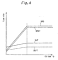
- a flow amount ULP which is slightly larger than a required flow amount ULPT (shown by a broken line in the drawing) is continuously supplied to the second lubricating circuit 35.
- the required flow amount ULPT of the second lubricating circuit 35 is smaller than the required flow amount BRGT of the first lubricating circuit 33.
- the second lubricating circuit 35 can lubricate the contact surface (the rolling surface) between the power rollers 18A to 18D and the input and output discs 19 to 22 by the working fluid having a relatively low temperature and not passing through the torque converter 12.
- the pressurized fluid supplied to the second lubricating circuit 35 does not pass through the oil cooler 32, little pressure loss results. Therefore the necessary flow amount can be ensured to the power roller rolling surface, shown by a solid line (ULP) in Fig. 4, even when using a traction oil having a high viscosity as the working fluid. Accordingly, even when the fluid temperature is significantly low, lubricating performance can be secured and a slip of the rolling surface can be securely prevented.
- ULP solid line
- the working fluid is supplied to the first lubricating circuit 33 connected to the downstream portion of the oil cooler 32 of the lubricating fluid passage 38.
- the torque converter pressure PT/C necessary for lock up can be secured prior to the first lubricating circuit 33.
- a flow amount restricted by the orifice 8 flows in to the first lubricating circuit 33.
- the working fluid passing to the engaging fluid chamber 12E from a releasing fluid chamber 12F through the torque converter 12 is led from the port 5C to the lubricating passage 38 when the lock up is in the OFF position, thereby joining in the flow amount from the orifice 8. However, they are supplied to the first lubricating circuit 33 after being cooled in the oil cooler 32.
- the working fluid is cooled by the oil cooler 32, so that the lubricating performance of the power roller bearing portion can be well maintained.
- the torque converter pressure PT/C is prevented from falling even when the lock up is in the ON position, so that the lock up clutch 12D can be securely fastened, thereby both improving the lubricating performance and securing the lock up performance.
- the second lubricating circuit 35 is disposed in the upstream side of the lock up control valve 5
- the high temperature working fluid heated by the torque converter 12 when the lock up is in the OFF position does not flow into the first lubricating circuit 35, so that the temperature of the power roller rolling surface is prevented from increasing and good lubricating performance can be secured.
- Fig. 5 shows a second embodiment of the invention.
- the embodiment is structured such that the second lubricating circuit 35 is disposed in parallel to a front portion lubricating circuit 34 for lubricating a forward/reverse change-over mechanism 13.
- a T/C regulator valve 3 for controlling the pressure PT/C in such a manner as not to exceed a pressure capable of being resisted by the torque converter 12 and a lock up regulator valve 4 for securing the PT/C necessary for the lock up prior to the flow amount to the lubricating fluid passage 37 are provided in the torque converter pressure circuit 31.
- a first drain of the T/C regulator valve 3 is connected with the lubricating fluid passage 37, a second drain is connected with a suction port 1A of the hydraulic pump 1, and a drain of the lock up regulator valve 4 is connected with the lubricating fluid passage 37.
- the torque converter pressure circuit 31 and the lubricating fluid passage 37 are connected with each other via the orifice 28 in addition to the drain mentioned above, thereby supplying at least the necessary flow amount to the lubricating fluid passage 37 via the orifice 28 even when the first drain of the T/C regulator valve 3 and the drain of the lock up regulator valve 4 are closed.
- an orifice 7 and a check valve 70 are interposed in the downstream portion of the lubricating fluid passage 37, and the front portion lubricating circuit 34 of the forward/reverse change-over mechanism 13 is connected to the downstream side thereof.
- a second lubricating circuit 35 is connected to the downstream portion of the check valve 70 through a lubricating fluid passage 39. Accordingly, the front portion lubricating circuit 34 and the second lubricating circuit 35 are mutually connected to each other in parallel.
- the check valve 70 Since the orifice 7 and the check valve 70 are present in the second lubricating circuit 35 and the lubricating circuit 37 disposed in the upstream portion of the front portion lubricating circuit 34, the check valve 70 is closed by a spring force when the engine is stopped, thereby preventing the working fluid of the engaging fluid chamber 12E and the releasing fluid chamber 12F of the torque converter 12 from flowing out into each of the lubricating circuits from the lubricating fluid passage 37, and also enabling a smooth speed change operation when starting the operation on a subsequent occasion.
- a lubricating fluid passage 38 is connected to the downstream side of the lock up control valve 5 provided in the torque converter pressure circuit 31, an oil cooler 32 is interposed to the passage 38, and a first lubricating circuit 33 is connected to the downstream thereof.
- the second lubricating circuit 35 connected to the downstream portion of the lubricating fluid passage 37 lubricates the rolling surface between the power rollers 18a to 18d and the input and output discs 19 to 22 by pressurized fluid continuously supplied from the torque converter pressure circuit 31 through the orifice 28 and pressurized fluid supplied from the torque converter pressure circuit 31 through the drain of the lock up regulator valve 4 or the first drain of the T/C regulator valve 3.
- lubrication due to the second lubricating circuit 35 can lubricate the rolling surface between the power rollers 18a to 18d and the input and output discs 19 to 22 by the working fluid not passing through the torque converter 12, thereby securing a good lubricating performance.
- the working fluid supplied to the lubricating fluid passage 37 does not pass through a circuit serving as a resistance, such as the oil cooler 32, a necessary amount supplied to the power roller rolling surface can be secured even when the fluid temperature is significantly low and the viscosity of the traction fluid is very high, such as when using a traction oil having a high viscosity as the working fluid. As a result, the lubricating performance can be well maintained.
- the first lubricating circuit 33 for lubricating the bearing member of the power rollers 18A to 18D has no orifice in the lubricating fluid passage 38, a necessary flow amount can be easily secured regardless of the engaging state of the lock up clutch 12D. Even when high load causes a high fluid temperature, the lubricating flow amount to the power roller bearing member can be increased, so that the lubricating performance can be improved.
- the lubricating fluid passage 37 is connected with the torque converter pressure circuit 31 via the orifice 28 in addition to the first drain of the T/C regulator valve 3 and the drain of the lock up regulator valve 4. Accordingly, even when the T/C regulator valve 3 and the lock up regulator valve 4 are both closed as when the line pressure PL is low, at least the flow amount necessary for lubricating the front portion lubricating circuit 34 and the upper link pivot lubricating circuit 35 can be supplied from the orifice 28, so that the lubricating performance of the toroidal continuously variable transmission 11 can be secured.
- the lock up regulator valve 4 for securing the torque converter pressure PT/C necessary for the lock up prior to lubrication, and the T/C regulator valve 3 which controls the torque converter pressure PT/C so that it does not exceed a predetermined upper limit value are provided in the torque converter pressure circuit 31.
- the drain ends of the T/C regulator valve 3 and the lock up regulator valve 4 are connected to the lubricating fluid passage 37, and the torque converter pressure circuit 31 and the lubricating fluid passage 37 are connected with each other through the orifice 28, so that the front portion lubricating circuit 34 and the second lubricating circuit 35 are connected to the downstream portion of the lubricating fluid passage 37 in parallel, thereby securing the lubricating flow amount necessary for the rolling surface even at a super low fluid temperature and as a result improving lubricating performance.
- the lock up control valve 5 is structured such as to directly connect the lubricating fluid passage 37 to the lubricating fluid passage 38 when the lock up is in the ON position, to connect the pressurized fluid passing through the engaging fluid chamber 12E from the releasing fluid chamber 12F to the lubricating fluid passage 38 at a time of the lock up OFF, and to lead to the power roller lubricating circuit 33 after being cooled by the cooler 32 of the lubricating fluid passage 38, and further since it is unnecessary to provide the orifice in the lubricating fluid passage 38 in this case, the flow amount to the first lubricating passage 33 is increased at a time of a high fluid temperature and a high load, so that the lubrication of the power roller bearing member can be securely performed.
- the engaging capacity of the lock up clutch 12D is not deteriorated. Since the flow amount can be secured as mentioned above, the traction fluid having a high viscosity can be used, so that a durability of the toroidal continuously variable transmission 11 can be further improved by improving the lubricating performance thereby.
Description
- The present invention relates to a hydraulic pressure control device of an automatic transmission for a vehicle.
- Japanese Patent Publication Tokkai Hei 4-78369 (JP-A-4 78369), which constitutes the closest prior art, discloses an automatic transmission for an automotive vehicle in which a torque converter with a lock up clutch, and a toroidal continuously variable transmission are combined.
- In the automatic transmission, in order to control the speed change ratio of the continuously variable transmission and engage and release the lock up clutch, a pressurized fluid is supplied from a single hydraulic pump the fluid functions as a lubricating fluid for each lubricating portion of the continuously variable transmission.
- In the toroidal continuously variable transmission, a power roller is disposed between an input disc and an output disc, the rotation in accordance with a contact friction there between is transferred and the speed change ratio is varied in a continuous manner in accordance with the angle of the incline of the power roller. In order to transmit high torque, a great contact pressure is applied between the power roller and the disc. As a result it is necessary to cool and lubricate these members by the application of considerable amounts of lubricating fluid. In this case, the lubricating fluid for the power roller and the disc portion can be divided into two lines. One is a fluid supply to the contact surface therebetween and another is a fluid supply to a bearing portion of the power roller.
- The lubricating fluid from the pump is supplied via a torque converter pressure circuit for operating the lock up clutch, and a fluid cooler for cooling a lubricating fluid itself is interposed in the middle thereof. Since a pressure loss is generated when the lubricating fluid passes through the oil cooler, a pump having a great capacity is required in order to secure a supply amount of the lubricating fluid to the power roller under an high power operating condition.
- Particularly, since high temperature working fluid enters the torque converter, after passing through the lock up clutch which is in a releasing state the fluid temperature becomes too high. Therefore lubricating and cooling performance deteriorates. Furthermore the durability of the torque converter is deteriorated, when lubricating fluid is supplied without passing through the oil cooler.
- An object of the present invention, which is claimed in independent claims 1 and 4, is to obtain good lubrication and cooling of a power transmitting element in a transmission without enlarging the capacity of a hydraulic pump.
- Another object of the present invention is to supply a necessary and sufficient fluid amount even to a lock up clutch.
- In order to achieve the above objects, the present invention provides a hydraulic pressure control device for use with an automatic transmission which comprises a toroidal continuously variable transmission having power rollers held between input discs and output discs which transmits power, the torque converter having a lock up clutch connected to the continuously variable transmission.
- The device comprises a pressure regulator valve for adjusting the line pressure of working fluid supplied to the continuously variable transmission from a pump to a predetermined pressure, a pressure passage for introducing the adjusted line pressure to the lock up clutch through a lock up control valve, an oil cooler provided downstream of the lock up control valve. The working fluid through the cooler is supplied to the lubricating circuit of the continuously variable transmission.
- The device further comprises that the lubricating circuit which is separated into a first lubricating circuit for lubricating a bearing member of the power rollers and a second lubricating circuit for lubricating a rolling surface between the input and output discs and the power rollers, the first lubricating circuit is connected downstream of the cooler and the second lubricating circuit is connected upstream of the lock up control valve.
- It is preferable that the device also comprises an orifice which is provided in a passage through which the working fluid may flow and bypass the lock up control valve. The cooler is connected to a downstream portion of the orifice.
- It is further preferable that the device further comprises a lock up control valve which introduces working fluid passing through the torque converter at a time of releasing the lock up clutch to the cooler without passing the fluid though the orifice. Conversely when the lock up clutch is fastened, the working fluid is introduced to the cooler from the upstream portion of the lock up control valve through the orifice by the lock up control valve.
- The present invention provides a hydraulic pressure control device which comprises a toroidal continuously variable transmission having power rollers held between input discs and output discs and which transmits power to a torque converter having a lock up clutch connected to the continuously variable transmission, the device comprises a pressure regulator valve for adjusting the line pressure of working fluid supplied to the continuously variable transmission from a pump to a predetermined pressure, a pressure passage for introducing the adjusted line pressure to the lock up clutch through a lock up control valve and an oil cooler provided in a downstream portion of the lock up control valve. The working fluid passing through the cooler is supplied to a lubricating circuit of the continuously variable transmission.
- The device further comprises a lock up regulator valve for adjusting to a pressure necessary for a lock up the valve being provided in the pressure passage, a lubricating fluid passage is connected to the drain end of the regulator valve, the lubricating fluid passage is connected to the pressure passage through an orifice, the lubricating circuit is separated into a first lubricating circuit for lubricating a bearing member of the power rollers and a second lubricating circuit for lubricating a rolling surface between the input and output discs and the power rollers, the first lubricating circuit is connected to a downstream portion of the cooler and the second lubricating circuit is connected to the lubricating fluid passage.
- It is further preferable that the device comprises a lock up control valve which introduces working fluid passing through the torque converter when the lock up clutch is released to the cooler when the lock up clutch is fastened the lock up control valve introduces the working fluid to the cooler from the lubricating fluid passage.
- It is further preferable that the device comprises a check valve for preventing working fluid of the torque converter from escaping when the pump is stopped, the check valve being interposed between the second lubricating circuit and the lubricating fluid passage.
- The details as well as other features and advantages of the present invention are set forth in the remainder of the specification and are shown in the accompaning drawings.
-
- Fig. 1 is a schematic diagram of a transmission apparatus applying the invention;
- Fig. 2 is a circuit diagram which shows a fluid pressure circuit of an apparatus for controlling a fluid pressure in accordance with the invention;
- Fig. 3 is a circuit diagram which shows a fluid pressure circuit of a lubricating system in a continuously variable transmitting mechanism in accordance with the invention;
- Fig. 4 is a graph which shows a ratio between a fluid temperature and a lubricating flow amount in accordance with the invention; and
- Fig. 5 is a circuit diagram of a fluid pressure similar to Fig. 2 which shows a second embodiment of the invention.
-
- With reference to Fig. 1, a transmission apparatus for a vehicle applying the invention comprises a
torque converter 12 with a lock upclutch 12D, and a continuouslyvariable transmission 11 with a forward /reverse change-overmechanism 13. A rotation of an engine (not shown) is input to aninput shaft 14 of thetorque converter 12, and anoutput shaft 15 of anautomatic transmission 11 rotates a drive wheel through a propeller shaft. The continuouslyvariable transmission 11 is constituted by a toroidal continuously variable transmission which is provided with a firsttoroidal transmitting portion 16 comprising aninput disc 19 and anoutput disc 21holding power rollers toroidal transmitting portion 17 comprising aninput disc 20 and anoutput disc 22holding power rollers - The continuously
variable transmission 11 realizes a desired speed change ratio by changing the angle of an incline of thepower rollers 18A to 18D by fluid pressure. The toroidal continuously variable transmission of this type is known, for example, from US Patent No. 5,542,890. - The transmission apparatus mentioned above is controlled by a hydraulic pressure control device shown in Fig. 2.
- In this hydraulic pressure control device, the discharge fluid of a hydraulic pump 1 driven by an engine is supplied to a
line pressure circuit 30, and the pressure thereof is adjusted to a predetermined line pressure PL by apressure control valve 2 provided in theline pressure circuit 30. The speed change ratio of the continuouslyvariable transmission 11 is controlled by using the line pressure PL. - In this case, a signal pressure PLSOL from a line
pressure solenoid valve 40 controlled in duty ratio by an electronic controller (not shown) is supplied to thepressure control valve 2, and the line pressure PL and pressure PT/C of a torqueconverter pressure circuit 31 are simultaneously controlled by a spool moving in accordance with the signal pressure PLSOL. - A relief valve 6 is connected to the torque
converter pressure circuit 31, and pressure defined by the relief valve 6 is supplied to the lock upcontrol valve 5. - The lock up
control valve 5 is provided with aspool 5E driven in accordance with a signal pressure PL/USOL from a lock upsolenoid valve 41 duty-controlled by an electronic controller. A port 5B connected to thepressure circuit 31 is connected to aport 5H or a 5G in accordance with the displacement of thespool 5E. Accordingly, the pressure PT/C of the port 5B is selectively supplied to afirst fluid chamber 12E of the lock upclutch 12D thorough theport 5G, or asecond fluid chamber 12F of the lock upclutch 12D through theport 5H. Therefore, the lock upclutch 12D is engaged or released. - Further, when the
spool 5E displaces so that the port 5B is connected with theport 5H, that is, the lock upclutch 12D is released, theport 5G is connected with theport 5C. Accordingly, the working fluid flowing through the lock upclutch 12D is led from theport 5G to theport 5C. - The
lubricating fluid passage 38 is connected to the torqueconverter pressure circuit 31 through theorifice 8, and the port 5B and theport 5C are respectively connected to an upstream portion and a downstream portion of theorifice 8. Accordingly, theorifice 8 is interposed in a passage bypassing the lock upcontrol valve 5. - An
oil cooler 32 for cooling lubricating fluid is disposed in thelubricating passage 38, and is connected to a first lubricatingcircuit 33 for supplying lubricating fluid to the bearing portion of the downstream power roller mentioned below. - Further, a
lubricating fluid passage 39 is branched from the torqueconverter pressure circuit 31 disposed in an upstream side of the lock upcontrol valve 5, and thelubricating fluid passage 39 is connected to a secondlubricating circuit 35 for supplying lubricating fluid to a contact surface between the power roller and the disc mentioned below. - Fig. 3 shows a lubricating circuit of a continuously variable transmission, the first lubricating
circuit 33 feeds lubricating fluid mainly to a power roller bearing portion by a fluid passage provided in such a manner as to extend an inner portion of atrunnion 23 for supportingpower rollers 18A to 18D of the first and second toroidalspeed change portions - Further, the second
lubricating circuit 35 injects lubricating fluid toward a contact surface between the power roller anddiscs upper link 24 mutually connecting thetrunnions 23 of thepower rollers 18A to 18D to each other, and performs lubrication and cooling thereof. - In this case, a required flow amount of the first lubricating
circuit 33 is generally larger than a required flow amount of the second lubricatingcircuit 35. - Next, the operation of the invention will be described below.
- The working fluid from the hydraulic pump 1 is adjusted a pressure in the
pressure regulator valve 2, and is introduced to the torqueconverter pressure circuit 31 therefrom. The working fluid of thepressure circuit 31 is supplied to the lock upcontrol valve 5 through the relief valve 6. At this time, when thespool 5E is shifted in response to the signal pressure PL/USOL from the lock upsolenoid valve 41, the lock up clutch 12d is engaged (lock up ON) or released (lock up OFF). - The torque converter pressure PT/C is always supplied to the
lubricating fluid passage 39 branching from the upstream portion of the relief valve 6 in the downstream portion of thepressure regulator 2. - As shown in Fig. 4, when the fluid temperature is equal to or more than a predetermined value (for example, room temperature), a flow amount ULP which is slightly larger than a required flow amount ULPT (shown by a broken line in the drawing) is continuously supplied to the
second lubricating circuit 35. - In this case, the required flow amount ULPT of the
second lubricating circuit 35 is smaller than the required flow amount BRGT of thefirst lubricating circuit 33. - Accordingly, the
second lubricating circuit 35 can lubricate the contact surface (the rolling surface) between thepower rollers 18A to 18D and the input andoutput discs 19 to 22 by the working fluid having a relatively low temperature and not passing through thetorque converter 12. - Since the pressurized fluid supplied to the
second lubricating circuit 35 does not pass through theoil cooler 32, little pressure loss results. Therefore the necessary flow amount can be ensured to the power roller rolling surface, shown by a solid line (ULP) in Fig. 4, even when using a traction oil having a high viscosity as the working fluid. Accordingly, even when the fluid temperature is significantly low, lubricating performance can be secured and a slip of the rolling surface can be securely prevented. - On the other hand, the working fluid is supplied to the
first lubricating circuit 33 connected to the downstream portion of theoil cooler 32 of the lubricatingfluid passage 38. - Since the working fluid is supplied to an engaging
fluid chamber 12E via the lock upcontrol valve 5 from the upstream portion of theorifice 8 when lock up is in the ON position, the torque converter pressure PT/C necessary for lock up can be secured prior to thefirst lubricating circuit 33. In this case, a flow amount restricted by theorifice 8 flows in to thefirst lubricating circuit 33. - The working fluid passing to the engaging
fluid chamber 12E from a releasingfluid chamber 12F through thetorque converter 12 is led from theport 5C to thelubricating passage 38 when the lock up is in the OFF position, thereby joining in the flow amount from theorifice 8. However, they are supplied to thefirst lubricating circuit 33 after being cooled in theoil cooler 32. - Since only the
first lubricating circuit 33 is connected to thelubricating fluid passage 38, the necessary flow amount is reduced. This is in contrast to the conventional embodiment in which all the fluid flow is for lubricating the power roller. As a result the lubricating fluid can be supplied in excess. - Accordingly, flow resistance due to the
oil cooler 32 decreses preportional to the degree of reduction of the flow amount. Therefore, as shown by the solid line in Fig. 4, it is possible to ensure that, from extremely low to high temperatures, the amount of fluid flow actually supplied (shown by the soild line BRG) is greater than the required fluid flow to lubricate the power roller bearing member (shown by the broken line BRGT). Accordingly, even when fluid temperature is high and there is high load, lubrication of the power roller bearing member can be securely performed. - Further, even in the case that the temperature of the working fluid is increased by passing it through the
torque converter 12, the working fluid is cooled by theoil cooler 32, so that the lubricating performance of the power roller bearing portion can be well maintained. - In this case, since the
second lubricating circuit 35 having a relatively smaller necessary flow amount is branched from the upstream portion of the lock upcontrol valve 5, the torque converter pressure PT/C is prevented from falling even when the lock up is in the ON position, so that the lock up clutch 12D can be securely fastened, thereby both improving the lubricating performance and securing the lock up performance. - Further, when the
second lubricating circuit 35 is disposed in the upstream side of the lock upcontrol valve 5, the high temperature working fluid heated by thetorque converter 12 when the lock up is in the OFF position does not flow into thefirst lubricating circuit 35, so that the temperature of the power roller rolling surface is prevented from increasing and good lubricating performance can be secured. - Fig. 5 shows a second embodiment of the invention.
- The embodiment is structured such that the
second lubricating circuit 35 is disposed in parallel to a frontportion lubricating circuit 34 for lubricating a forward/reverse change-overmechanism 13. - A T/
C regulator valve 3 for controlling the pressure PT/C in such a manner as not to exceed a pressure capable of being resisted by thetorque converter 12 and a lock up regulator valve 4 for securing the PT/C necessary for the lock up prior to the flow amount to thelubricating fluid passage 37 are provided in the torqueconverter pressure circuit 31. - A first drain of the T/
C regulator valve 3 is connected with the lubricatingfluid passage 37, a second drain is connected with a suction port 1A of the hydraulic pump 1, and a drain of the lock up regulator valve 4 is connected with the lubricatingfluid passage 37. - The torque
converter pressure circuit 31 and the lubricatingfluid passage 37 are connected with each other via theorifice 28 in addition to the drain mentioned above, thereby supplying at least the necessary flow amount to thelubricating fluid passage 37 via theorifice 28 even when the first drain of the T/C regulator valve 3 and the drain of the lock up regulator valve 4 are closed. - Then, an orifice 7 and a
check valve 70 are interposed in the downstream portion of the lubricatingfluid passage 37, and the frontportion lubricating circuit 34 of the forward/reverse change-overmechanism 13 is connected to the downstream side thereof. Asecond lubricating circuit 35 is connected to the downstream portion of thecheck valve 70 through a lubricatingfluid passage 39. Accordingly, the frontportion lubricating circuit 34 and thesecond lubricating circuit 35 are mutually connected to each other in parallel. - Since the orifice 7 and the
check valve 70 are present in thesecond lubricating circuit 35 and thelubricating circuit 37 disposed in the upstream portion of the frontportion lubricating circuit 34, thecheck valve 70 is closed by a spring force when the engine is stopped, thereby preventing the working fluid of the engagingfluid chamber 12E and the releasingfluid chamber 12F of thetorque converter 12 from flowing out into each of the lubricating circuits from the lubricatingfluid passage 37, and also enabling a smooth speed change operation when starting the operation on a subsequent occasion. - Furthermore, a lubricating
fluid passage 38 is connected to the downstream side of the lock upcontrol valve 5 provided in the torqueconverter pressure circuit 31, anoil cooler 32 is interposed to thepassage 38, and afirst lubricating circuit 33 is connected to the downstream thereof. - As shown in the drawing, when the lock up is in the OFF position,in which the spool of the lock up
control valve 5 is displaced upward, the torqueconverter pressure circuit 31 is connected to the releasingfluid chamber 12F, and the working fluid returned to the lock upcontrol valve 5 through the engagingfluid chamber 12E from the releasingfluid chamber 12F is led to thelubricating fluid passage 38 and supplied to thefirst lubricating circuit 33 after being cooled by theoil cooler 32. - On the other hand when the lock up of the lock up
control valve 5 is in the ON position, the spool is displaced to the lower portion in the drawing, the torqueconverter pressure circuit 31 is connected with the engagingfluid chamber 12E, and the releasingfluid chamber 12F is connected to the tank. The lubricatingfluid passage 37 is connected with the lubricatingfluid passage 38 via the lock upcontrol valve 5. - The
second lubricating circuit 35 connected to the downstream portion of the lubricatingfluid passage 37 lubricates the rolling surface between thepower rollers 18a to 18d and the input andoutput discs 19 to 22 by pressurized fluid continuously supplied from the torqueconverter pressure circuit 31 through theorifice 28 and pressurized fluid supplied from the torqueconverter pressure circuit 31 through the drain of the lock up regulator valve 4 or the first drain of the T/C regulator valve 3. - Accordingly, lubrication due to the
second lubricating circuit 35 can lubricate the rolling surface between thepower rollers 18a to 18d and the input andoutput discs 19 to 22 by the working fluid not passing through thetorque converter 12, thereby securing a good lubricating performance. - Since the working fluid supplied to the
lubricating fluid passage 37 does not pass through a circuit serving as a resistance, such as theoil cooler 32, a necessary amount supplied to the power roller rolling surface can be secured even when the fluid temperature is significantly low and the viscosity of the traction fluid is very high, such as when using a traction oil having a high viscosity as the working fluid. As a result, the lubricating performance can be well maintained. - Further, since the
first lubricating circuit 33 for lubricating the bearing member of thepower rollers 18A to 18D has no orifice in thelubricating fluid passage 38, a necessary flow amount can be easily secured regardless of the engaging state of the lock up clutch 12D. Even when high load causes a high fluid temperature, the lubricating flow amount to the power roller bearing member can be increased, so that the lubricating performance can be improved. - Still further, since the engaging capacity of the lock up clutch 12D is secured by the pressure PT/C set by the lock up regulator valve 4, a good lock up performance can be secured even when the line pressure PL corresponding to the fluid pressure of the
line pressure circuit 30 is low. - The lubricating
fluid passage 37 is connected with the torqueconverter pressure circuit 31 via theorifice 28 in addition to the first drain of the T/C regulator valve 3 and the drain of the lock up regulator valve 4. Accordingly, even when the T/C regulator valve 3 and the lock up regulator valve 4 are both closed as when the line pressure PL is low, at least the flow amount necessary for lubricating the frontportion lubricating circuit 34 and the upper linkpivot lubricating circuit 35 can be supplied from theorifice 28, so that the lubricating performance of the toroidal continuouslyvariable transmission 11 can be secured. - As mentioned above, the lock up regulator valve 4 for securing the torque converter pressure PT/C necessary for the lock up prior to lubrication, and the T/
C regulator valve 3 which controls the torque converter pressure PT/C so that it does not exceed a predetermined upper limit value are provided in the torqueconverter pressure circuit 31. The drain ends of the T/C regulator valve 3 and the lock up regulator valve 4 are connected to thelubricating fluid passage 37, and the torqueconverter pressure circuit 31 and the lubricatingfluid passage 37 are connected with each other through theorifice 28, so that the frontportion lubricating circuit 34 and thesecond lubricating circuit 35 are connected to the downstream portion of the lubricatingfluid passage 37 in parallel, thereby securing the lubricating flow amount necessary for the rolling surface even at a super low fluid temperature and as a result improving lubricating performance. - Further, since the lock up
control valve 5 is structured such as to directly connect thelubricating fluid passage 37 to thelubricating fluid passage 38 when the lock up is in the ON position, to connect the pressurized fluid passing through the engagingfluid chamber 12E from the releasingfluid chamber 12F to thelubricating fluid passage 38 at a time of the lock up OFF, and to lead to the powerroller lubricating circuit 33 after being cooled by the cooler 32 of the lubricatingfluid passage 38, and further since it is unnecessary to provide the orifice in thelubricating fluid passage 38 in this case, the flow amount to thefirst lubricating passage 33 is increased at a time of a high fluid temperature and a high load, so that the lubrication of the power roller bearing member can be securely performed. Further, the engaging capacity of the lock up clutch 12D is not deteriorated. Since the flow amount can be secured as mentioned above, the traction fluid having a high viscosity can be used, so that a durability of the toroidal continuouslyvariable transmission 11 can be further improved by improving the lubricating performance thereby.
Claims (6)
- Hydraulic pressure control device for use with an automatic transmission which provides a toroidal continuously variable transmission (11) having power rollers (18A-18D) held between input discs (19, 29) and output discs (21, 22) and transmitting a power, a torque converter (12) having a lock up clutch (12D) connected to said continuously variable transmission (11) comprising :characterized in thata pressure regulator valve (2) for adjusting a line pressure of a working fluid supplied to said continuously variable transmission (11) from a pump (1) to a predetermined pressure;a pressure passage (31) for introducing the adjusted line pressure to said lock up clutch (12D) through a lock up control valve (5);an oil cooler (32) provided in a downstream portion of said lock up control valve (5); andthe working fluid through said cooler (32) being supplied to a lubricating circuit of said continuously variable transmission (11),
said lubricating circuit is separated into a first lubricating circuit 33 for lubricating a bearing member of said power rollers (18A-18D) and a second lubricating circuit (35) for lubricating a rolling surface between said input and output discs (19-22) and said power rollers (18A-18D), said first lubricating circuit (33) is connected to a downstream portion of said cooler (32) and said second lubricating circuit (35) is connected to an upstream portion of said lock up control valve (5). - A hydraulic pressure control device according to claim 1, wherein an orifice (8) is provided in a passage for flowing a working fluid by bypassing said lock up control valve (5), said cooler (32) being connected to a downstream portion of the orifice (8).
- A hydraulic pressure control device according to claim 2, wherein said lock up control valve (5) introduces a working fluid passing through the torque converter (12) at a time of releasing said lock up clutch (12D) to said cooler (32) without passing though said orifice (8), and, at a time of fastening said lock up clutch (12D), said working fluid is introduced to said cooler (32) from the upstream portion of said lock up control valve (5) through said orifice (8) by said lock up control valve (5).
- A hydraulic pressure control device for use is an automatic trasmission which provides a toroidal continuously variable transmission (11) having power rollers (18A-18D) held between input discs (19, 29) and output discs (21, 22) and transmitting power, a torque converter (12) having a lock up clutch (12D) connected to said continuously variable transmission (11) comprising;characterized in thata pressure regulator valve (2) for adjusting a line pressure of a working fluid supplied to said continuously variable transmission (11) from a pump (1) to a predetermined pressure;a pressure passage (31) for introducing the adjusted line pressure to said lock up clutch (12D) through a lock up control valve (5);an oil cooler (32) provided in a downstream portion of said lock up control valve (5); andthe working fluid through said cooler (32) being supplied to a lubricating circuit of said continuously variable transmission (11),
a lock up regulator valve (4) for adjusting the pressure to that necessary for a lock up is provided in said pressure passage (31), a lubricating fluid passage (37) is connected to a drain end of the regulator valve (4), said lubricating fluid passage (37) is connected to said pressure passage (31) through an orifice (28), said lubricating circuit is separated into a first lubricating circuit 33 for lubricating a bearing member of said power rollers (18A-18D) and a second lubricating circuit (35) for lubricating a rolling surface between said input and output discs (19-22) and said power rollers (18A-18D), said first lubricating circuit (33) is connected to a downstream portion of said cooler (32) and said second lubricating circuit (35) is connected to said lubricating fluid passage (37). - A hydraulic pressure control device according to claim 4, wherein said lock up control valve (5) introduces a working fluid passing through the torque converter (12) at a time of releasing said lock up clutch (12D) to said cooler (32) and, at a time of fastening said lock up clutch, (12D) introduces the working fluid to said cooler (32) from the lubricating fluid passage (37).
- A hydraulic pressure control device according to claim 4, wherein a check valve (70) for preventing a working fluid of said torque converter (12) from escaping when said pump is not in operation is interposed between said second lubricating circuit (35) and said lubricating fluid passage (37).
Applications Claiming Priority (3)
| Application Number | Priority Date | Filing Date | Title |
|---|---|---|---|
| JP18399497 | 1997-07-09 | ||
| JP18399497A JP3277850B2 (en) | 1997-07-09 | 1997-07-09 | Hydraulic control device for toroidal type continuously variable transmission |
| JP183994/97 | 1997-07-09 |
Publications (3)
| Publication Number | Publication Date |
|---|---|
| EP0890761A2 EP0890761A2 (en) | 1999-01-13 |
| EP0890761A3 EP0890761A3 (en) | 2000-12-06 |
| EP0890761B1 true EP0890761B1 (en) | 2002-01-02 |
Family
ID=16145469
Family Applications (1)
| Application Number | Title | Priority Date | Filing Date |
|---|---|---|---|
| EP98112666A Expired - Lifetime EP0890761B1 (en) | 1997-07-09 | 1998-07-08 | Hydraulic pressure control device of automatic transmission |
Country Status (4)
| Country | Link |
|---|---|
| US (2) | US6045480A (en) |
| EP (1) | EP0890761B1 (en) |
| JP (1) | JP3277850B2 (en) |
| DE (1) | DE69803338T2 (en) |
Families Citing this family (12)
| Publication number | Priority date | Publication date | Assignee | Title |
|---|---|---|---|---|
| JP3592093B2 (en) * | 1998-08-10 | 2004-11-24 | ジヤトコ株式会社 | Lubrication structure of toroidal type continuously variable automatic transmission |
| JP3698931B2 (en) | 1999-09-30 | 2005-09-21 | ジヤトコ株式会社 | Hydraulic circuit of toroidal type continuously variable transmission |
| JP2002021960A (en) * | 2000-07-03 | 2002-01-23 | Nissan Motor Co Ltd | Lubricating mechanism of troidal type continuously variable transmission |
| US20030155182A1 (en) * | 2000-07-07 | 2003-08-21 | Bernhard Sich | Device and method for accurately supplying components of an automatic gearbox for motor vehicles |
| DE10033085A1 (en) * | 2000-07-07 | 2002-01-17 | Zahnradfabrik Friedrichshafen | Device and method for the targeted supply of components of an automatic transmission for motor vehicles |
| JP2007177977A (en) * | 2005-12-28 | 2007-07-12 | Aisin Aw Co Ltd | Automatic transmission |
| JP4935343B2 (en) * | 2006-12-21 | 2012-05-23 | トヨタ自動車株式会社 | Hydraulic control device for continuously variable transmission |
| JP4978185B2 (en) * | 2006-12-21 | 2012-07-18 | トヨタ自動車株式会社 | Hydraulic control device for continuously variable transmission |
| JP5177026B2 (en) * | 2009-03-12 | 2013-04-03 | アイシン・エィ・ダブリュ株式会社 | Hydraulic control device for automatic transmission |
| US9383003B2 (en) * | 2012-06-18 | 2016-07-05 | Gm Global Technology Operations, Llc | Hydraulic control system for a continuously variable transmission |
| EP3428482B1 (en) * | 2016-03-07 | 2022-12-14 | Kawasaki Jukogyo Kabushiki Kaisha | Controller of a toroidal continuously variable transmission |
| WO2021111899A1 (en) * | 2019-12-06 | 2021-06-10 | ジヤトコ株式会社 | Transmission and transmission control method |
Family Cites Families (14)
| Publication number | Priority date | Publication date | Assignee | Title |
|---|---|---|---|---|
| US4464946A (en) * | 1983-01-26 | 1984-08-14 | Excelermatic Inc. | Control arrangement for the supply of lubricant to the bearings of an infinitely variable traction roller transmission |
| JP2787064B2 (en) * | 1987-03-31 | 1998-08-13 | アイシン精機株式会社 | Control circuit of fluid coupling with direct coupling |
| JPH0539238Y2 (en) * | 1988-11-22 | 1993-10-05 | ||
| US5219055A (en) * | 1989-09-08 | 1993-06-15 | Jatco Corporation | Lock-up clutch pressure control device |
| JP2878724B2 (en) * | 1989-09-08 | 1999-04-05 | ジャトコ株式会社 | Hydraulic control device for lock-up clutch |
| JP2846362B2 (en) * | 1989-09-26 | 1999-01-13 | ジャトコ株式会社 | Hydraulic control device for lock-up clutch |
| JP2663672B2 (en) * | 1990-04-04 | 1997-10-15 | 日産自動車株式会社 | Hydraulic control system for friction wheel type continuously variable transmission |
| JP2661339B2 (en) | 1990-07-19 | 1997-10-08 | 日産自動車株式会社 | Line pressure control device for continuously variable transmission |
| JPH05187540A (en) * | 1992-01-09 | 1993-07-27 | Jatco Corp | Lock-up clutch control device |
| US5163540A (en) * | 1992-02-24 | 1992-11-17 | Saturn Corporation | Control valving for a torque converter and clutch assembly |
| US5251734A (en) * | 1992-05-08 | 1993-10-12 | Chrysler Corporation | Hydraulic controls for lock-up clutch of a torque converter assembly |
| JP3125553B2 (en) | 1993-12-24 | 2001-01-22 | 日産自動車株式会社 | Friction wheel type continuously variable transmission |
| US5553694A (en) * | 1994-10-14 | 1996-09-10 | Ford Motor Company | Multiple ratio automatic transmission and torque converter |
| US5722519A (en) * | 1994-10-14 | 1998-03-03 | Ford Global Technologies, Inc. | Multiple ratio automatic transmission and torque converter |
-
1997
- 1997-07-09 JP JP18399497A patent/JP3277850B2/en not_active Expired - Fee Related
-
1998
- 1998-07-08 DE DE69803338T patent/DE69803338T2/en not_active Expired - Fee Related
- 1998-07-08 EP EP98112666A patent/EP0890761B1/en not_active Expired - Lifetime
- 1998-07-09 US US09/112,444 patent/US6045480A/en not_active Expired - Fee Related
-
2000
- 2000-03-09 US US09/521,610 patent/US6142906A/en not_active Expired - Fee Related
Also Published As
| Publication number | Publication date |
|---|---|
| JPH1130317A (en) | 1999-02-02 |
| JP3277850B2 (en) | 2002-04-22 |
| EP0890761A2 (en) | 1999-01-13 |
| US6142906A (en) | 2000-11-07 |
| US6045480A (en) | 2000-04-04 |
| DE69803338D1 (en) | 2002-02-28 |
| DE69803338T2 (en) | 2002-09-19 |
| EP0890761A3 (en) | 2000-12-06 |
Similar Documents
| Publication | Publication Date | Title |
|---|---|---|
| JP3095258B2 (en) | Hydraulic control device for continuously variable transmission with lock-up torque converter | |
| US6017286A (en) | Power train | |
| US7128688B2 (en) | Hydraulic control for automatic transmission | |
| EP0890761B1 (en) | Hydraulic pressure control device of automatic transmission | |
| EP0980995B1 (en) | Lubrication pressure controller | |
| US7669701B2 (en) | Hydraulic pressure control apparatus for a vehicular power transmitting device | |
| JP3806257B2 (en) | Oil supply device | |
| JP3461846B2 (en) | Continuously adjustable conical belt wheel wrapping transmission | |
| US6350215B1 (en) | Hydraulic control system for pressure control of a CVT variator with limp home mode | |
| US6364802B1 (en) | Hydraulic control system for a continuously variable transmission | |
| JP3635190B2 (en) | Hydraulic control device for automatic transmission | |
| JPH04272556A (en) | Regulating device for automatic transmission unit | |
| JP2002533629A (en) | Hydraulic control unit for continuously variable transmissions | |
| US6068569A (en) | Automatic transmission hydraulic control system with parallel lubrication and cooler circuits | |
| JP2005180620A (en) | Lubricating/cooling device for continuously variable transmission for vehicle | |
| US6527668B2 (en) | Hydraulic system | |
| US5792019A (en) | Continuously variable transmission with torque converter for a vehicle and hydraulic control system for controlling the same | |
| JP3630883B2 (en) | Hydraulic control circuit for continuously variable transmission | |
| JP3892511B2 (en) | Hydraulic control device for automatic transmission | |
| JPH03204472A (en) | Hydraulic pressure control device for vehicle automatic transmission | |
| JP3118905B2 (en) | Cooling oil control device for continuously variable transmission | |
| JP4652511B2 (en) | Hydraulic control device for continuously variable transmission | |
| JP2994766B2 (en) | Oil cooler flow control device for automatic transmission | |
| JP3602276B2 (en) | Hydraulic control circuit for continuously variable transmission | |
| JP3786753B2 (en) | Hydraulic control circuit for continuously variable transmission |
Legal Events
| Date | Code | Title | Description |
|---|---|---|---|
| PUAI | Public reference made under article 153(3) epc to a published international application that has entered the european phase |
Free format text: ORIGINAL CODE: 0009012 |
|
| 17P | Request for examination filed |
Effective date: 19980713 |
|
| AK | Designated contracting states |
Kind code of ref document: A2 Designated state(s): DE FR GB |
|
| AX | Request for extension of the european patent |
Free format text: AL;LT;LV;MK;RO;SI |
|
| PUAL | Search report despatched |
Free format text: ORIGINAL CODE: 0009013 |
|
| AK | Designated contracting states |
Kind code of ref document: A3 Designated state(s): AT BE CH CY DE DK ES FI FR GB GR IE IT LI LU MC NL PT SE |
|
| AX | Request for extension of the european patent |
Free format text: AL;LT;LV;MK;RO;SI |
|
| GRAG | Despatch of communication of intention to grant |
Free format text: ORIGINAL CODE: EPIDOS AGRA |
|
| 17Q | First examination report despatched |
Effective date: 20010402 |
|
| GRAG | Despatch of communication of intention to grant |
Free format text: ORIGINAL CODE: EPIDOS AGRA |
|
| GRAH | Despatch of communication of intention to grant a patent |
Free format text: ORIGINAL CODE: EPIDOS IGRA |
|
| AKX | Designation fees paid |
Free format text: DE FR GB |
|
| GRAH | Despatch of communication of intention to grant a patent |
Free format text: ORIGINAL CODE: EPIDOS IGRA |
|
| GRAA | (expected) grant |
Free format text: ORIGINAL CODE: 0009210 |
|
| REG | Reference to a national code |
Ref country code: GB Ref legal event code: IF02 |
|
| AK | Designated contracting states |
Kind code of ref document: B1 Designated state(s): DE FR GB |
|
| REF | Corresponds to: |
Ref document number: 69803338 Country of ref document: DE Date of ref document: 20020228 |
|
| ET | Fr: translation filed | ||
| PLBE | No opposition filed within time limit |
Free format text: ORIGINAL CODE: 0009261 |
|
| STAA | Information on the status of an ep patent application or granted ep patent |
Free format text: STATUS: NO OPPOSITION FILED WITHIN TIME LIMIT |
|
| 26N | No opposition filed | ||
| PGFP | Annual fee paid to national office [announced via postgrant information from national office to epo] |
Ref country code: DE Payment date: 20080724 Year of fee payment: 11 |
|
| PGFP | Annual fee paid to national office [announced via postgrant information from national office to epo] |
Ref country code: FR Payment date: 20080718 Year of fee payment: 11 |
|
| PGFP | Annual fee paid to national office [announced via postgrant information from national office to epo] |
Ref country code: GB Payment date: 20080709 Year of fee payment: 11 |
|
| GBPC | Gb: european patent ceased through non-payment of renewal fee |
Effective date: 20090708 |
|
| REG | Reference to a national code |
Ref country code: FR Ref legal event code: ST Effective date: 20100331 |
|
| PG25 | Lapsed in a contracting state [announced via postgrant information from national office to epo] |
Ref country code: FR Free format text: LAPSE BECAUSE OF NON-PAYMENT OF DUE FEES Effective date: 20090731 |
|
| PG25 | Lapsed in a contracting state [announced via postgrant information from national office to epo] |
Ref country code: GB Free format text: LAPSE BECAUSE OF NON-PAYMENT OF DUE FEES Effective date: 20090708 |
|
| PG25 | Lapsed in a contracting state [announced via postgrant information from national office to epo] |
Ref country code: DE Free format text: LAPSE BECAUSE OF NON-PAYMENT OF DUE FEES Effective date: 20100202 |