EP0892339B1 - A method and system for defining the movement path of a multimedia object - Google Patents
A method and system for defining the movement path of a multimedia object Download PDFInfo
- Publication number
- EP0892339B1 EP0892339B1 EP98303508A EP98303508A EP0892339B1 EP 0892339 B1 EP0892339 B1 EP 0892339B1 EP 98303508 A EP98303508 A EP 98303508A EP 98303508 A EP98303508 A EP 98303508A EP 0892339 B1 EP0892339 B1 EP 0892339B1
- Authority
- EP
- European Patent Office
- Prior art keywords
- path
- user
- layout area
- multimedia object
- movement
- Prior art date
- Legal status (The legal status is an assumption and is not a legal conclusion. Google has not performed a legal analysis and makes no representation as to the accuracy of the status listed.)
- Expired - Lifetime
Links
Images


Classifications
-
- G—PHYSICS
- G06—COMPUTING; CALCULATING OR COUNTING
- G06F—ELECTRIC DIGITAL DATA PROCESSING
- G06F3/00—Input arrangements for transferring data to be processed into a form capable of being handled by the computer; Output arrangements for transferring data from processing unit to output unit, e.g. interface arrangements
- G06F3/01—Input arrangements or combined input and output arrangements for interaction between user and computer
- G06F3/048—Interaction techniques based on graphical user interfaces [GUI]
- G06F3/0484—Interaction techniques based on graphical user interfaces [GUI] for the control of specific functions or operations, e.g. selecting or manipulating an object, an image or a displayed text element, setting a parameter value or selecting a range
- G06F3/04845—Interaction techniques based on graphical user interfaces [GUI] for the control of specific functions or operations, e.g. selecting or manipulating an object, an image or a displayed text element, setting a parameter value or selecting a range for image manipulation, e.g. dragging, rotation, expansion or change of colour
Description
- This invention relates in general to computer software, and in particular to a method and system for defining the movement path of a multimedia object in an application development environment.
- In a multimedia application development environment, users often want to assign a path along which the part will move to give the application special effects. For example, a user might want to display an animation of a bird appearing on the left edge of a page and flying across the page to exit on the right side of the page. Using the known techniques, the assignment of a motion path to a part is tedious. In addition, the known techniques have limited flexibility and require construction separate from the part layout area. Once constructed, it is difficult to modify the path.
- One type of path definition is found in, for example, Premier by Adobe. To construct a path for an object/part, the user must exit the layout area and enter a separate window. Then, the user can draw a path for the part using a pointing device. There is no one-to-one scale and the path is drawn without the perspective of the actual environment including lack of true-scale surrounding parts. Thus, the user must create the path and then assign it, return to the layout area and run a test. If the path does not work as expected, the user must return to the separate path definition window and try again. This is awkward and time consuming, especially in complex layouts.
- Another type of path definition can be found in Director by Macromedia. This type of path definition allows the use of the actual layout area for construction but also requires the use of a "score" area. The user must drag the part to the start time in the score. Then the user must drag the part to the next movement position in the layout followed by another dragging to the score area for the time it should appear in that position. Once these steps have occurred from start point to finish point, the score area is highlighted and the placement is made on the layout area. Thus, this method can also be slow and tedious.
- Further examples of path definitions are described in
EP 0 309 373 A and GB 2 258 790 A. - Thus, there is a need for a method and system for path definition that is quick and easy to use, especially for complex arrangements of multiple parts of any type using multiple paths.
- The present invention as defined in
claims 1 to 3 comprises a method and system for defining a movement path of a multimedia object which greatly reduces problems associated with the prior art. The present invention allows the creation and modification of a movement path without the need for a separate path dialogue. - In accordance with one aspect of the present invention, a movement path is defined for a multimedia object in an application development environment. A multimedia object is placed in a layout area of the application development environment. A movement path is then specified within the layout area for the object using a pointing device.
- The object may either be dragged along the movement path by the pointing device or individual points may be selected with the pointing device to define the movement path.
- Once the path has been defined, the path may be easily modified. The user may add or delete points by simply selecting a point with the pointing device for addition or deletion. In addition, the user may combine two or more movement paths into one.
- The present invention provides the technical advantage of being able to simply and intuitively create and modify a movement path for a multimedia object in an application development environment. Previously created and stored paths may be reused and or added to newly created paths, thus, providing greater flexibility for the developer.
- For a more complete understanding of the present invention and for further advantages thereof, reference is now made to the following Detailed Description taken in conjunction with the accompanying drawings, in which:
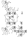
- Figure 1 is a pictorial representation of a data processing system which may be utilised to implement a method and system of the present invention;
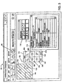
- Figure 2 is a graphical representation of a multimedia parts editor;
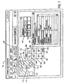
- Figures 3,4 and 5 are graphical representations of the multimedia editor of Fig. 1 utilising a path editor in accordance with the present invention;
- Figure 6 illustrates use of the present invention to define a path utilising various anchor points;
- Figure 7 illustrates the use of the present invention to add or delete an anchor point to a path;
- Figure 8 illustrates use of the present invention to define a curved path; and
- Figure 9 illustrates the use of the present invention to join a predefined and stored path to a newly created path.
-
- Referring to Figure 1, there is depicted a graphical representation of a
data processing system 8, which may be utilised to implement the present invention. As may be seen,data processing system 8 may include a plurality of networks, such as Local Area Networks (LAN) 10 and 32, each of which preferably includes a plurality ofindividual computers - As is common in such data processing systems, each individual computer may be coupled to a
storage device 14 and/or a printer/output device 16 and may be provided with a pointing device such as amouse 17. - The
data processing system 8 may also include multiple mainframe computers, such asmainframe computer 18, which may be preferably coupled toLAN 10 by means ofcommunications link 22. Themainframe computer 18 may also be coupled to astorage device 20 which may serve as remote storage forLAN 10. Similarly,LAN 10 may be coupled viacommunications link 24 through a sub-system control unit/communications controller 26 andcommunications link 34 to agateway server 28. Thegateway server 28 is preferably an IWS which serves to linkLAN 32 toLAN 10. - With respect to
LAN 32 and LAN 10, a plurality of documents or resource objects maybe stored withinstorage device 20 and controlled bymainframe computer 18, as resource manager or library service for the resource objects thus stored. Of course, those skilled in the art will appreciate thatmainframe computer 18 may be located a great geographic distance fromLAN 10 and similarly,LAN 10 may be located a substantial distance fromLAN 32. For example, LAN 32 may be located in California while LAN 10 may be located within North Carolina andmainframe computer 18 may be located in New York. - Software program code which employs the present invention is typically stored in the memory of a
storage device 14 of a stand alone workstation or LAN server from which a developer may access the code for distribution purposes, the software program code may be embodied on any of a variety of known media for use with a data processing system such as a diskette or CD-ROM or may be distributed to users from a memory of one computer system over a network of some type to other computer systems for use by users of such other systems. Such techniques and methods for embodying software code on media and/or distributing software code are well-known and will not be further discussed herein. - Referring to Figure 2, a graphical representation of a multimedia part editor is shown in
window 100. Within thepart editor 100 there appears a layout area, generally indicated byreference numeral 102, in which a plurality of multimedia objects/parts, for example,square 104,triangle 106 andcircle 108, are positioned for manipulation. Apalette window 110 and aDetails window 112 are also provided. Thepalette window 110 contains a collection of parts available for use in the current application being developed. These may include multimedia parts(image, sound, animation, etc) and/or controls (buttons, labels, listboxes, etc). - The
Details window 112 is used to modify and customise the specific parts used in the current application and add logic between parts. - A
Properties tab 113 in theDetails window 112 provides a method to modify the parts by allowing the user to customise specific characteristics of parts in the current application. For example, the picture property of an image part can be any source file (in the correct format) that the user desires. AConnections tab 115 of theDetails window 112 provides a method to add logic between parts in the "part, event - part, action/property" format. For example, a user can add logic between a button and a sound file so that when the button is clicked, the sound file will play. This connection would read: "button clicked - sound play". - Referring to Figure 3, upon pressing a
motion path button 98 on a main toolbar or by selecting "Motion Path Editor" (not shown) via an appropriate menu choice, apath editor window 114 appears adjacent to thelayout area 102. A part specific path can also be created by first selecting a part to apply the path to and then pressing themotion path button 98 on the main toolbar or by selecting "Motion Path Editor" via the appropriate menu choice. Thepath window 114 is provided with a plurality of buttons and tools (which will be subsequently described in greater detail), including a "Record" push-button 130 and a "Join" push-button 132. In addition, all the parts/images within thelayout area 102 are slightly ghosted when themotion path window 114 is first displayed, as indicated by the diagonal lines appearing therethrough. - Referring to Figure 4, the user has selected an object, for example, the square 104, to which a path will be assigned.
- As shown in Figure 4, the square 104 has become unghosted (shown without diagonal lines). There are two methods for creating the motion path for
square 104. First, the user can press the record push-button 130, and while holding the mouse button down, drag the square 104 manually in thelayout area 102 to define a path. In the second method, the user can manually define individual points along which the square 104 will follow for its path. - Referring to Figure 5, an example of the manual drag technique to assign a path is shown. The user presses the Record push-
button 130, and then places acursor 150 over the object to be moved, for example, the square 104, and drags the object along a path (shown as line 105) of the desired movement. When the user has reached the point at which he/she would like the path to end, the user releases the mouse button and the path "record" activity ceases. When set into motion, the square 104 will then move along thepath 105 as drawn. - Referring to Figure 6, the setting of anchor points technique is shown. The user can define as many anchor points as desired, for example,
anchor point 160 andanchor point 162 with the initial anchor point defined as the physical centre (not shown) of the object. A connecting line is automatically drawn between anchor points as each subsequent anchor point is defined. To indicate the end of the path, the user double-clicks the mouse at the location of the end point, this action completes the path. When set in motion, the object (square 104) will then move along the path as defined by the anchor points. - Referring to Figure 7, having already defined a motion path as identified by
line 170 from the square 104 through anchor points 172, 174 and 176, the user decides that thepath 170 needs to be modified. To add a point on thepath 170, the user selects an anchor point "Add"tool 204 from thepath editor window 114 and moves thecursor 150 over the desired location for a new anchor point 171 and presses the mouse button. This adds the new anchor point 171 on thepath 170. To delete an existing point from thepath 170, the user selects the anchor point "Delete"tool 208 from thepath editor window 114, moves thecursor 150 over the existing point to be deleted and presses the mouse button. This deletes the indicated anchor point from thepath 170. - Referring to Figure 8, a technique for curving a path is illustrated. The user defines a curve by simply holding and dragging the mouse as the anchor point is being laid, producing an anchor point with two
handles tool 210 in thepath editor window 114. Similarly, to make a curve point anchor point into a straight line anchor point, the user can select the curve point anchor point on thelayout area 102 and press an anchor point "straight line"tool 206 on thepath editor window 114. - Referring to Figure 9, a technique is illustrated for joining two or more movement paths.
- Any two or more paths can be joined by selecting an end anchor point, for example,
anchor point 220, of afirst path 221 to be joined and anend anchor point 222 of asecond path 224 and pressing the "Join"button 132 on thepath editor window 114. A position of the two points is averaged in both a horizontal and a vertical direction and one point is created from the two at the resulting position. The user can also select the two anchor points (points 220 and 222) to be joined by clicking the mouse and dragging a dynamically sized box around the two points and pressing the "Join"button 132 on thepath editor window 114. - Thus the present invention offers strong advantages over traditional motion path editors. As described herein, the present invention allows the definition of a true-scale path without requiring the use of a separate path editor dialogue. Also provided herein are easy to use methods for path (including curved paths) construction, modification, and joining.
Claims (3)
- A method of defining a movement path of a multimedia object in an application development environment, characterised by the steps of:placing a multimedia object (104) in a layout area (102) of the application development environment; andspecifying a plurality of movement paths (105) within said layout area for said object with a pointing device (17) without the need to enter a separate path layout editor.joining the plurality of movement paths (221,224) to form a single movement path.
- A system for defining a movement path of a multimedia object in an application development environment, characterised by:means for placing a multimedia object (104) in a layout area (102) of the application development environment; andmeans for specifying a plurality of movement paths (105) within said layout area for said object with a pointing device (17) without the need to enter a separate path layout editor.means for joining the plurality of movement paths (221,224) to form a single movement path.
- A computer program product recorded on computer readable medium for defining a movement path of a multimedia object in an application development environment, characterised by comprising:computer readable means for placing a multimedia object (104) in a layout area (102) of the application development environment; andcomputer readable means for specifying a plurality of movement paths (105) within said layout area for said object with a pointing device (17) without the need to enter a separate path layout editor.computer readable means for joining the plurality of movement paths (221, 224) to form a single movement path.
Applications Claiming Priority (2)
| Application Number | Priority Date | Filing Date | Title |
|---|---|---|---|
| US896817 | 1997-07-18 | ||
| US08/896,817 US6108010A (en) | 1997-07-18 | 1997-07-18 | Method and system for a true-scale motion path editor |
Publications (2)
| Publication Number | Publication Date |
|---|---|
| EP0892339A1 EP0892339A1 (en) | 1999-01-20 |
| EP0892339B1 true EP0892339B1 (en) | 2003-01-02 |
Family
ID=25406903
Family Applications (1)
| Application Number | Title | Priority Date | Filing Date |
|---|---|---|---|
| EP98303508A Expired - Lifetime EP0892339B1 (en) | 1997-07-18 | 1998-05-05 | A method and system for defining the movement path of a multimedia object |
Country Status (4)
| Country | Link |
|---|---|
| US (1) | US6108010A (en) |
| EP (1) | EP0892339B1 (en) |
| JP (1) | JPH1186024A (en) |
| DE (1) | DE69810393T2 (en) |
Families Citing this family (12)
| Publication number | Priority date | Publication date | Assignee | Title |
|---|---|---|---|---|
| FR2785717B1 (en) * | 1998-11-05 | 2000-12-08 | Schneider Electric Sa | THERMAL RELAY WITH SPRING BLADE MECHANISM |
| US20060129933A1 (en) * | 2000-12-19 | 2006-06-15 | Sparkpoint Software, Inc. | System and method for multimedia authoring and playback |
| AU2002231289A1 (en) * | 2000-12-19 | 2002-07-01 | Coolernet, Inc. | System and method for multimedia authoring and playback |
| US7213229B2 (en) * | 2003-02-28 | 2007-05-01 | Archvision, Inc. | Content-based graphical user interface |
| US7358973B2 (en) * | 2003-06-30 | 2008-04-15 | Microsoft Corporation | Mixture model for motion lines in a virtual reality environment |
| US8456475B2 (en) * | 2003-06-30 | 2013-06-04 | Microsoft Corporation | Motion line switching in a virtual environment |
| JP4603931B2 (en) | 2005-05-16 | 2010-12-22 | 任天堂株式会社 | Object movement control device and object movement control program |
| US8913064B2 (en) | 2010-06-14 | 2014-12-16 | Nintendo Co., Ltd. | Real-time terrain animation selection |
| US8821234B2 (en) * | 2011-06-14 | 2014-09-02 | Nintendo Co., Ltd. | Methods and/or systems for designing virtual environments |
| US8601366B2 (en) * | 2011-09-08 | 2013-12-03 | Microsoft Corporation | Visualization and editing of composite layouts |
| JP6361146B2 (en) | 2013-05-09 | 2018-07-25 | 株式会社リコー | Display control program, display control method, display control apparatus, and display system |
| CN110908749B (en) * | 2019-10-25 | 2023-07-11 | 北京达佳互联信息技术有限公司 | Layout generation method and device for display object |
Family Cites Families (22)
| Publication number | Priority date | Publication date | Assignee | Title |
|---|---|---|---|---|
| US3637212A (en) * | 1969-03-24 | 1972-01-25 | Funtronics Inc | Bird shoot game and the like |
| US4841291A (en) * | 1987-09-21 | 1989-06-20 | International Business Machines Corp. | Interactive animation of graphics objects |
| US5355314A (en) * | 1990-03-26 | 1994-10-11 | Hammond Incorporated | Method and apparatus for automatically generating symbol images against a background image without collision utilizing distance-dependent attractive and repulsive forces in a computer simulation |
| US5287446A (en) * | 1990-10-15 | 1994-02-15 | Sierra On-Line, Inc. | System and methods for intelligent movement on computer displays |
| GB2258790A (en) * | 1991-08-12 | 1993-02-17 | Cambridge Animation Syst | Animation |
| US5261041A (en) * | 1990-12-28 | 1993-11-09 | Apple Computer, Inc. | Computer controlled animation system based on definitional animated objects and methods of manipulating same |
| GB2303282B (en) * | 1992-09-10 | 1997-04-16 | Fujitsu Ltd | Graphic editing apparatus |
| JP3186240B2 (en) * | 1992-09-10 | 2001-07-11 | 富士通株式会社 | Figure editing device |
| US5758180A (en) * | 1993-04-15 | 1998-05-26 | Sony Corporation | Block resizing function for multi-media editing which moves other blocks in response to the resize only as necessary |
| AU7338394A (en) * | 1993-08-04 | 1995-03-14 | Aficionado, Inc | Computerized game teaching method |
| US5510995A (en) * | 1993-08-13 | 1996-04-23 | Iowa State University Research Foundation, Inc. | Sculptured surface synthesis based on functional design constraints |
| JPH0816820A (en) * | 1994-04-25 | 1996-01-19 | Fujitsu Ltd | Three-dimensional animation generation device |
| US5818462A (en) * | 1994-07-01 | 1998-10-06 | Digital Equipment Corporation | Method and apparatus for producing complex animation from simpler animated sequences |
| US5767861A (en) * | 1994-08-11 | 1998-06-16 | Kabushiki Kaisha Sega Enterprises | Processing apparatus and method for displaying a moving figure constrained to provide appearance of fluid motion |
| US5594856A (en) * | 1994-08-25 | 1997-01-14 | Girard; Michael | Computer user interface for step-driven character animation |
| US5680533A (en) * | 1994-10-31 | 1997-10-21 | Nintendo Co., Ltd. | Videographics program/video game fabricating system and method |
| US5577185A (en) * | 1994-11-10 | 1996-11-19 | Dynamix, Inc. | Computerized puzzle gaming method and apparatus |
| US5680619A (en) * | 1995-04-03 | 1997-10-21 | Mfactory, Inc. | Hierarchical encapsulation of instantiated objects in a multimedia authoring system |
| US5572639A (en) * | 1995-05-08 | 1996-11-05 | Gantt; Brian D. | Method and apparatus for interactively manipulating and displaying presumptive relationships between graphic objects |
| JP2915826B2 (en) * | 1995-07-11 | 1999-07-05 | 富士通株式会社 | Interference check device |
| US5692144A (en) * | 1995-08-03 | 1997-11-25 | Microsoft Corporation | Method and system for depicting an object springing back from a position |
| US5793382A (en) * | 1996-06-10 | 1998-08-11 | Mitsubishi Electric Information Technology Center America, Inc. | Method for smooth motion in a distributed virtual reality environment |
-
1997
- 1997-07-18 US US08/896,817 patent/US6108010A/en not_active Expired - Fee Related
-
1998
- 1998-05-05 DE DE69810393T patent/DE69810393T2/en not_active Expired - Lifetime
- 1998-05-05 EP EP98303508A patent/EP0892339B1/en not_active Expired - Lifetime
- 1998-06-16 JP JP16827598A patent/JPH1186024A/en active Pending
Also Published As
| Publication number | Publication date |
|---|---|
| US6108010A (en) | 2000-08-22 |
| DE69810393D1 (en) | 2003-02-06 |
| DE69810393T2 (en) | 2003-10-30 |
| JPH1186024A (en) | 1999-03-30 |
| EP0892339A1 (en) | 1999-01-20 |
Similar Documents
| Publication | Publication Date | Title |
|---|---|---|
| US6111590A (en) | Method and system for a true scale motion path editor to create motion paths as independent entities | |
| US6091427A (en) | Method and system for a true-scale motion path editor using time segments, duration and synchronization | |
| US8024672B1 (en) | System and method for generating presentations | |
| US7707503B2 (en) | Methods and systems for supporting presentation tools using zoomable user interface | |
| US5861885A (en) | Method and apparatus for indicating selected objects by spotlight | |
| US6842176B2 (en) | Computer-related method and system for controlling data visualization in external dimension(s) | |
| US5555354A (en) | Method and apparatus for navigation within three-dimensional information landscape | |
| US6570587B1 (en) | System and method and linking information to a video | |
| EP0892339B1 (en) | A method and system for defining the movement path of a multimedia object | |
| CA2094526C (en) | Method and apparatus for creating a multi-media footnote control in a video data | |
| CA1241759A (en) | Editing business charts | |
| US5634016A (en) | Event management system | |
| US4674043A (en) | Updating business chart data by editing the chart | |
| US7600198B2 (en) | Method of tracking data objects using related thumbnails in a palette window | |
| US7023452B2 (en) | Image generation system, image generating method, and storage medium storing image generation program | |
| US20090177964A1 (en) | Visual wizard launch pad | |
| EP1550973A1 (en) | Graphical representation, storage and dissemination of displayed thinking | |
| US6025838A (en) | Interactive display interface for media presentation with direct access to media sequences | |
| US7098933B1 (en) | Acquiring and unacquiring alignment and extension points | |
| JP2002509630A (en) | Multimedia project management and control system | |
| US6417865B1 (en) | Affinitive placement by proximity in a computer-implemented graphics system | |
| JPH09274553A (en) | Device and method for controlling window display | |
| JPH06149648A (en) | Hypermedium system | |
| TWI835471B (en) | Method for editing layout plan, system and computer-readable storage medium | |
| JP5097346B2 (en) | Server system |
Legal Events
| Date | Code | Title | Description |
|---|---|---|---|
| PUAI | Public reference made under article 153(3) epc to a published international application that has entered the european phase |
Free format text: ORIGINAL CODE: 0009012 |
|
| AK | Designated contracting states |
Kind code of ref document: A1 Designated state(s): DE FR GB |
|
| AX | Request for extension of the european patent |
Free format text: AL;LT;LV;MK;RO;SI |
|
| 17P | Request for examination filed |
Effective date: 19990617 |
|
| AKX | Designation fees paid |
Free format text: DE FR GB |
|
| 17Q | First examination report despatched |
Effective date: 20020124 |
|
| GRAH | Despatch of communication of intention to grant a patent |
Free format text: ORIGINAL CODE: EPIDOS IGRA |
|
| GRAH | Despatch of communication of intention to grant a patent |
Free format text: ORIGINAL CODE: EPIDOS IGRA |
|
| GRAA | (expected) grant |
Free format text: ORIGINAL CODE: 0009210 |
|
| AK | Designated contracting states |
Kind code of ref document: B1 Designated state(s): DE FR GB |
|
| PG25 | Lapsed in a contracting state [announced via postgrant information from national office to epo] |
Ref country code: FR Free format text: LAPSE BECAUSE OF FAILURE TO SUBMIT A TRANSLATION OF THE DESCRIPTION OR TO PAY THE FEE WITHIN THE PRESCRIBED TIME-LIMIT Effective date: 20030102 |
|
| REG | Reference to a national code |
Ref country code: GB Ref legal event code: FG4D Free format text: 20030102 |
|
| REF | Corresponds to: |
Ref document number: 69810393 Country of ref document: DE Date of ref document: 20030206 Kind code of ref document: P |
|
| PG25 | Lapsed in a contracting state [announced via postgrant information from national office to epo] |
Ref country code: GB Free format text: LAPSE BECAUSE OF NON-PAYMENT OF DUE FEES Effective date: 20030505 |
|
| PLBE | No opposition filed within time limit |
Free format text: ORIGINAL CODE: 0009261 |
|
| STAA | Information on the status of an ep patent application or granted ep patent |
Free format text: STATUS: NO OPPOSITION FILED WITHIN TIME LIMIT |
|
| EN | Fr: translation not filed | ||
| GBPC | Gb: european patent ceased through non-payment of renewal fee |
Effective date: 20030505 |
|
| 26N | No opposition filed |
Effective date: 20031003 |
|
| PGFP | Annual fee paid to national office [announced via postgrant information from national office to epo] |
Ref country code: DE Payment date: 20100521 Year of fee payment: 13 |
|
| REG | Reference to a national code |
Ref country code: DE Ref legal event code: R119 Ref document number: 69810393 Country of ref document: DE |
|
| REG | Reference to a national code |
Ref country code: DE Ref legal event code: R119 Ref document number: 69810393 Country of ref document: DE |
|
| PG25 | Lapsed in a contracting state [announced via postgrant information from national office to epo] |
Ref country code: DE Free format text: LAPSE BECAUSE OF NON-PAYMENT OF DUE FEES Effective date: 20111130 |