EP0893190A2 - Constructive body and friction stir welding method - Google Patents
Constructive body and friction stir welding method Download PDFInfo
- Publication number
- EP0893190A2 EP0893190A2 EP98305692A EP98305692A EP0893190A2 EP 0893190 A2 EP0893190 A2 EP 0893190A2 EP 98305692 A EP98305692 A EP 98305692A EP 98305692 A EP98305692 A EP 98305692A EP 0893190 A2 EP0893190 A2 EP 0893190A2
- Authority
- EP
- European Patent Office
- Prior art keywords
- face
- friction stir
- rib
- stir welding
- welding
- Prior art date
- Legal status (The legal status is an assumption and is not a legal conclusion. Google has not performed a legal analysis and makes no representation as to the accuracy of the status listed.)
- Granted
Links
Images


Classifications
-
- B—PERFORMING OPERATIONS; TRANSPORTING
- B23—MACHINE TOOLS; METAL-WORKING NOT OTHERWISE PROVIDED FOR
- B23K—SOLDERING OR UNSOLDERING; WELDING; CLADDING OR PLATING BY SOLDERING OR WELDING; CUTTING BY APPLYING HEAT LOCALLY, e.g. FLAME CUTTING; WORKING BY LASER BEAM
- B23K20/00—Non-electric welding by applying impact or other pressure, with or without the application of heat, e.g. cladding or plating
- B23K20/12—Non-electric welding by applying impact or other pressure, with or without the application of heat, e.g. cladding or plating the heat being generated by friction; Friction welding
- B23K20/122—Non-electric welding by applying impact or other pressure, with or without the application of heat, e.g. cladding or plating the heat being generated by friction; Friction welding using a non-consumable tool, e.g. friction stir welding
-
- B—PERFORMING OPERATIONS; TRANSPORTING
- B23—MACHINE TOOLS; METAL-WORKING NOT OTHERWISE PROVIDED FOR
- B23K—SOLDERING OR UNSOLDERING; WELDING; CLADDING OR PLATING BY SOLDERING OR WELDING; CUTTING BY APPLYING HEAT LOCALLY, e.g. FLAME CUTTING; WORKING BY LASER BEAM
- B23K33/00—Specially-profiled edge portions of workpieces for making soldering or welding connections; Filling the seams formed thereby
- B23K33/004—Filling of continuous seams
- B23K33/008—Filling of continuous seams for automotive applications
-
- B—PERFORMING OPERATIONS; TRANSPORTING
- B23—MACHINE TOOLS; METAL-WORKING NOT OTHERWISE PROVIDED FOR
- B23K—SOLDERING OR UNSOLDERING; WELDING; CLADDING OR PLATING BY SOLDERING OR WELDING; CUTTING BY APPLYING HEAT LOCALLY, e.g. FLAME CUTTING; WORKING BY LASER BEAM
- B23K2101/00—Articles made by soldering, welding or cutting
- B23K2101/04—Tubular or hollow articles
- B23K2101/045—Hollow panels
-
- Y—GENERAL TAGGING OF NEW TECHNOLOGICAL DEVELOPMENTS; GENERAL TAGGING OF CROSS-SECTIONAL TECHNOLOGIES SPANNING OVER SEVERAL SECTIONS OF THE IPC; TECHNICAL SUBJECTS COVERED BY FORMER USPC CROSS-REFERENCE ART COLLECTIONS [XRACs] AND DIGESTS
- Y10—TECHNICAL SUBJECTS COVERED BY FORMER USPC
- Y10T—TECHNICAL SUBJECTS COVERED BY FORMER US CLASSIFICATION
- Y10T403/00—Joints and connections
- Y10T403/47—Molded joint
- Y10T403/477—Fusion bond, e.g., weld, etc.
-
- Y—GENERAL TAGGING OF NEW TECHNOLOGICAL DEVELOPMENTS; GENERAL TAGGING OF CROSS-SECTIONAL TECHNOLOGIES SPANNING OVER SEVERAL SECTIONS OF THE IPC; TECHNICAL SUBJECTS COVERED BY FORMER USPC CROSS-REFERENCE ART COLLECTIONS [XRACs] AND DIGESTS
- Y10—TECHNICAL SUBJECTS COVERED BY FORMER USPC
- Y10T—TECHNICAL SUBJECTS COVERED BY FORMER US CLASSIFICATION
- Y10T428/00—Stock material or miscellaneous articles
- Y10T428/12—All metal or with adjacent metals
- Y10T428/12451—Macroscopically anomalous interface between layers
-
- Y—GENERAL TAGGING OF NEW TECHNOLOGICAL DEVELOPMENTS; GENERAL TAGGING OF CROSS-SECTIONAL TECHNOLOGIES SPANNING OVER SEVERAL SECTIONS OF THE IPC; TECHNICAL SUBJECTS COVERED BY FORMER USPC CROSS-REFERENCE ART COLLECTIONS [XRACs] AND DIGESTS
- Y10—TECHNICAL SUBJECTS COVERED BY FORMER USPC
- Y10T—TECHNICAL SUBJECTS COVERED BY FORMER US CLASSIFICATION
- Y10T428/00—Stock material or miscellaneous articles
- Y10T428/12—All metal or with adjacent metals
- Y10T428/12486—Laterally noncoextensive components [e.g., embedded, etc.]
Definitions
- the present invention relates to a friction stir welding method and relates to a joint shape member and a welding method the same.
- the present invention relates to a friction stir welding suitable for use in an aluminum alloy member which is employed for use a car body of a railway car and a constructive body etc..
- a friction stir welding method is a method in which by rotating a round-shape rod (herein after it is called as a rotary body) inserted in a joining region and further moving the rotary body along to a joining line, the joining portion is heated, and the material is softened and plastically flown and thus the material is solid-phase joined.
- a round-shape rod herein after it is called as a rotary body
- the rotary body comprises a small diameter portion which is inserted in the joining portion and a large diameter portion which is positioned outside the small diameter portion.
- the small diameter portion and the large diameter portion are positioned on the same axis. A side of the large diameter portion is rotated. A boundary portion between the small diameter portion and the large diameter portion can be inserted a little into the joining region.
- a joining according to the friction stir welding method can be applied to an abutting portion and an overlapping portion.
- the above stated technique is disclosed, for example, in Japanese patent announcement laid-open publication No. 505090 (EP 0615480 B1) and "Welding & Metal Fabrication (January 1995), pages 13-14 and 16.
- Japanese patent laid-open publication No. Hei 9-309164 (laid-open date: December 2, 1997) (EP 0797043 A2 (laid-open date: September 24, 1997) relates to a friction stir welding method about a hollow shape member and discloses as a center a rib for connecting two face sheets the friction stir welding is carried out.
- Japanese patent laid-open publication is laid-opened after a first application (Japanese patent application No. Hei 9-196761 (application date: July 23, 1997) of the present application.
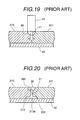
- Two members 310 and 311 to be welded (for example, aluminum alloys) have a substantially same thickness of a joining portion and are placed in parallel each other and further have vertical abutting faces 313. Under a condition to which the abutting faces 313 are contacted each other, and further under a condition in which the two members 310 and 311 are fixed to a bed stand 40, the friction stir welding method is carried out.
- a rotary body 20 as a joining use tool comprised of a round shape rod having a concave shape small diameter portion 21 at a lower end
- the concave shape small diameter portion 21 is inserted to joint shape members, at this condition the rotary body 20 is moved along to an abutting portion of the two members 310 and 311 and then the two members 310 and 311 are welded.
- a substantially flat boundary portion 20b formed between the small diameter portion 21 and a large diameter portion 20a is positioned a little toward a lower portion from upper portions of the two members 310 and 311. Since a length of the small diameter portion 21 is smaller than the thickness of the two members 310 and 311, the welding is carried out only on upper face sides of the two members 310 and 311. Namely, a non-penetration type friction stir welding method is carried out.
- a vicinity of the rotary body 20 presents a plastic flow condition.
- a plastic flow body at a plastic flow area 30 is tried to discharge to a surface but a move in the most part is restrained by the boundary portion 20b.
- the plastic flow body 31 is flown out toward the lower portion of the plastic flow area 30 and an enlarged clearance 313s is generated at the lower portion. Further, a volume part of the plastic flow body 31 which is flown out toward the plastic flow area 30 is insufficient, voids 380 for forming a defect generate on the plastic flow area 30. Therefore, a normal welding can not carried out. Further, the plastic flow area shows a substantial a welding bead 30.
- the inventors of the present invention discovered the above stated phenomenon through various experimentation.
- the non-penetration I type joint shape members in a case where a clearance formed between the abutting faces 313 and 313 before the welding is more than 0.2 mm, they found out that a good welding can not carried out.
- the friction stir welding is carried out by setting forth a premise that the clearance formed between the abutting faces 313 and 313 is extremely small as stated in the above.
- a large scale constructive body such as a car body of a railway car, in a case where the friction stir welding is carried on extruded frame members having about 25 m, a clearance becomes larger due to an accuracy of the extruded frame member, as a result it is difficult to carry out the welding.
- a first preferred object of the present invention is to obtain a good friction stir welding.
- a second preferred object of the present invention is to weld suitably a member such as a hollow shape member.
- a third preferred object of the present invention is to obtain a light weight structure of a member such as a hollow shape member.
- a fourth preferred object of the present invention is to carry out a good welding at a start point and a finish point of the welding.
- the invention provides a method comprising providing a slanting surface on an abutting face for welding two members and by welding a vicinity of said slanting surface using a friction stir welding method.
- the invention provides a method comprising providing a V shape projecting portion at an end portion of one of hollow shape members and by providing a dent portion to which said projecting portion is entered at another of the hollow shape members.
- the invention provides a method comprising friction stir welding using a rotary body which has a diameter larger than a space formed between a rib for connecting two face sheets of one of hollow shape members and a rib for connecting said two face sheets of another of said hollow shape members.
- the invention provides a method comprising arranging a tab at a start point and a finish point of welding and by welding a constructive body including said tab.
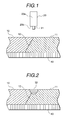
- Fig. 1 to Fig. 10 show a basic construction.
- a material for each of metal members 10 and 11 as a member to be welded is an aluminum alloy, for example.
- Each of the metal member can be applied to a car body of a railway car shown in from Fig. 8 to Fig. 10.
- Slanting surfaces 12 are provided on all faces of an abutting face of the members 10 and 11 (for example, an aluminum alloy) to be welded. At an abutting portion of upper face sides of the members 10 and 11, a center of a small diameter portion 21 of a rotary body 20 is positioned.
- the rotary body 20 provides the small diameter portion having a small diameter 21 at a tip end a round-shape rod having a large diameter.
- the welding is carried out by rotating the rotary body 20 the rotary body 20 is inserted to the members 10 and 11 and the rotary body 20 is moved along to a joining line.
- a boundary portion 20b formed between the large diameter portion 20a and the small diameter portion 21 of the rotary body 20 is indented toward a large diameter portion 20a side and has a circular arc shape.
- the small diameter portion 21 is formed with a screw member.
- a back end of the boundary portion 20 is entered to the members 10 and 11 but a front end thereof is positioned at upper portions of the members 10 and 11.
- the above stated “back end” and “front end” etc. are standardized the moving direction of the rotary body 20.
- a tip end of the small diameter portion 21 does not penetrate the members 10 and 11.
- the members 10 and 11 are pushed down and restricted from an upper portion to a bed stand 40 by a vise or an apparatus.
- An interval in a horizontal direction of the members 10 and 11 is made small and the slanting surfaces are contacted or a clearance between the abutting faces are made small as possible.
- the contact of the slant spaces 12 is carried out by pressing against the member 10 toward for the member 11 (in Fig. 1, a left and right direction). During the welding working, a left side and a right side of the rotary body 20 are pressed against the bed stand 40 from the upper portion.
- Reference numeral 30 denotes a welding bead according to the friction stir welding. A configuration of the welding bead 30 shown in Fig. 2 is expressed schematically.
- a welding bead 30 portion of the upper portion side member 10 is supported by the slanting surface 12 of the lower portion side member 11.
- the member 10 at a vicinity of the welding bead 30 does not bend by a large vertical force which is acted on the friction stir welding working. This will be understood easily by removing the slanting surface 12 from the member 11.
- the member 11 can not be positioned at the upper portion against the member 10, accordingly a slip-off of an upper face height can be lessened. In particularly to, in a case where the slanting surfaces 12 of the members 10 and 11 are contacted, a large effect can be expected.
- a constructive body is formed by welding the two members 10 and 11.
- the slanting surface 12 may be formed with a linear line or a circular arc having a concave portion a little at the upper portion.
- the welding of the lower portion side of the abutting faces is carried out by reversing the members or using a construction shown in an embodiment in Fig. 5.
- an abutting face of a joining portion of the members 10 and 11 according to the friction stir welding is formed with a vertical face 13 and a lower portion of the vertical face is formed with the slanting surface 12. At least the slanting surface 12 is provided at a lower portion from the welding bead 30.
- the slanting surface 12 is desirable to contact to the welding bead 30.
- the vertical face 13 is orthogonal to outer faces of the upper portions of the members 10 and 11. Further, at an upper portion of the vertical face 13, projecting portions 14 are projected, such a projecting portion is projected the outside portion (in Fig. 3, an upper portion) from the outer faces of the members 10 and 11.
- the shape of the projecting portion 14 has a trapezoidal shape as shown in Fig. 3 when the two projecting portions 14 and 14 are abutted.
- the boundary portion 20b is positioned at an outside portion from the outer face of a non-projecting portion of the members 10 and 11. Namely the boundary portion 20b is positioned between an apex of the projecting portion 14 and the non-projecting portion, namely the boundary portion is positioned in the projecting portion 14.
- a front end of the moving direction of the rotary body 20 is positioned at an upper portion from upper faces of the projecting portions 14 and 14.
- a tip end (in Fig. 3, a lower end) of the small diameter portion 21 is positioned at an upper end of the slanting surface 12. h 2 ⁇ h 1 .
- the welding portion (the welding bead 30) is the vertical face, the welding portion can be formed symmetrically with the small diameter portion 21 at a center.
- a height position of the boundary portion 20b of the small diameter portion 21 and the large diameter portion 20a of the rotary body 20 is positioned at a range of a height h3.
- a center of the projecting portion 14 is positioned in the vertical face 13.
- a width L1 of the upper ends of the two projecting portions 14 and 14 is larger than the diameter of the large diameter portion 20a of the rotary body 20.
- a projecting portion 14 side is desirable to arrange the outer side of the car body.
- the metals of the projecting portions 14 and 14 are moved to the clearance of the vertical faces 13 and 13 and the clearance is buried.
- the inventors confirmed cleanly that a tolerance value of the clearance of the vertical faces 13 and 13 before the welding can be enlarged about 1 mm by the experimentation about the aluminum alloy member.
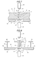
- the first stir welding is carried out simultaneously to the members 10 and 11 of the embodiment shown in Fig. 1 from both the upper face and the lower face.
- a center of the small diameter portion 21 of an upper portion rotary body 20 is positioned.
- a center of the small diameter portion 21 of a lower portion rotary body 20 is positioned.
- the small diameter portion 21 of the lower portion rotary body 20 is directed for the upper portion.
- an operation point of a load (a force for inserting the rotary body 20 to the member) according to the upper portion rotary body 20 and an operation point of a load according to the lower portion rotary body 20 are made to not separate largely. Therefore, the bends of the members 10 and 11 are prevented.
- No bed stand 400 exits at a periphery of the lower portion rotary body 20.
- a bed stand 40 is positioned toward the vertical direction of the upper portion rotary body 20.
- the abutting faces of the upper face side and the lower face side of the members 10 and 11 are formed by the vertical faces 13 and 13. In the vertical direction of the upper portion vertical face 13, the lower portion vertical face 13 does not exist. Between both vertical faces is connected by a slanting surface 12.
- the abutting faces of the upper face side and the lower face side of the members 10 and 11 are formed with vertical faces 13 and 13.
- the lower portion verticals faces 13 and 13 are existed on an extension line of the upper portion vertical faces 13 and 13.
- the abutting faces between the upper and lower vertical faces 13 and 13 are formed with V shape slanting surfaces 12 and 12.
- An end portion of the member 11 is formed with V shape concave portion and an end portion of the member 10 is formed with V shape dent portion.
- the dimension control is carried out even when the vertical faces are not contacted each other, the slanting surfaces 12 and 12 are contacted each other or approached each other.
- an interval of the slanting surfaces 12 and 12 of the dent portion is set to be smaller than an interval of the slanting surfaces 12 and 12 of the concave portion.
- the lower portion rotary body 20 is substantially positioned at the lower portion of the upper portion rotary body 20, the bends of the members 10 and 11 can be lessened further. Further, by the provision of V shape slanting surfaces 12, the slip-off toward the upper and the lower directions of the members 10 and 11 can be prevented. As a result, a good friction stir welding can be obtained.
- the bottom portion of the V shape dent portion of the member 10 and the apex portion of the V shape concave portion of the member 11 are not provided but a trapezoid shape structure is formed. Further, a clearance 16 is provided between the vertical faces 15 and 15 of the members 10 and 11. With this construction, the contact between the upper and the lower vertical faces 13 and 13 are formed easily.
- next two clearances are easily to occur.
- One of the two clearances is a clearance between the faces 345 and 356.
- Another of the two clearances is clearance between a tip end (a vertical face) of the flange 343 and a joining face (a vertical face) of the shape member 341.
- the car body of the railway car is constituted by a side constructive body 50 which constitutes a side face of the car body, an upper face roof constructive body 51, a lower face floor constructive body 52, and an end portion at a longitudinal direction end constructive body 53.
- the side constructive body 50 is constituted that by arranging in parallel plural extruded frame members 60 and 70 and by welding an abutting portion those according to the friction stir welding working.
- Each of the roof constructive body 51 and the floor constructive body 52 is constituted similarly to the side constructive body 50.
- the welding between the side constructive body 50 and the roof constructive body 51 and the welding between the side constructive body 50 and the floor constructive body 51 are carried out using an MIG (metal electrode inert gas) welding, etc.
- MIG metal electrode inert gas
- the extruded frame members 60 and 70 are corresponded to the members 10 and 11 of the embodiment shown in from Fig. 1 to Fig. 7, respectively.
- the extruded frame members 60 and 70 are comprised of faces plates 61 and 71 which constitute the outer face of the car body, plural ribs 62, 63 and 72, 73 at a car inner side, and face sheets 65, 66 and 75, 76 which are provided of tip portions of the ribs. Plural ribs 63 and 73 and plural face sheets 66 and 76 are provided along to a width direction of the extruded frame members 60 and 70.
- a post in a case of the side constructive body 50, not shown
- a rafter in a case of the roof constructive body 51, not shown
- a lateral beam in a case of the floor constructive body 52, not shown
- installing seats for various components are welded.
- the configuration of the joint shape member is substantially similarly to that of Fig. 7. Similarly to the embodiment shown in Fig. 7, the friction stir welding is carried out simultaneously to both upper and lower faces.
- a roller (not shown) for supporting the upper portion rotary body 20 is mounted on the face sheets 65 and 75.
- One end of the frame member 60 has a concave trapezoid shape and one end of the frame member 70 has a dent trapezoid shape.
- Another end of the frame member 60 has the shape of the above stated one end frame member 70 or the shape of the above stated one end of the frame member 60. The two frame members are able to be assembled.
- the extrude frame members 60 and 70 have two-plane structures as stated in the above.
- One of the planes are the face sheets 61 and 71 and another of the planes are face sheets 65, 66 and 75 and 76.
- face sheets 65, 66 and 75 and 76 are face sheets 65, 66 and 75 and 76.
- the rib 62 can works a support member for receiving the vertical load during the friction stir welding.
- the rib 62 is existed on a line for connecting the vertical faces 13 and 13.
- the vertical faces 13 and 13 are existed on a range of an extension line of the plate thickness of the rib 62. In the above stated range, at least parts of the welding beads 30 and 30 are positioned.
- the above stated joint shape member can be applied to a hollow extruded frame member to which the face sheets 65, 66 (75, 76, 77) are connected.
- the projecting portion 14 is cut off, and the outer face is made to a flat smooth structure. It is not always necessarily to carry out the cut off of the projecting portion in the car inner side. After that a finishing may be carried out through a painting finish, but it will be explained in a case where the painting finish is not carried out.
- a hair line finish, or a transparent painting finish is carried out. Since the friction stir welding is carried out, the joining portion can not confirmed through a visual observation in comparison with MIG welding. As a result, a texture can be appeared but it can be obtained a good show of the side constructive body. It can be obtained by a low cost.
- the welding portions of the side constructive body 50, the roof constructive body 51, the floor constructive body 52, and the end constructive body 53 are positioned at a position difficult to see in the side constructive side.
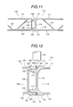
- An extruded frame member 100 (110) comprises substantially parallel two face sheets 101 and 102 (111 and 112), plural ribs 103 and 106 (113 and 116) for connecting the two face sheets, a projecting portion 104 (114) which is projected toward a thickness directions of the frame members 110 and 110 in an end portion of a joining portion, and projecting parts 117 and 117 which are projected toward the opposing frame member 110 from the end portion rib 106.
- the plural ribs 103 and 113 are provided along to a width direction of the frame members 100 and 110.
- the rib 103 (113) is provided to incline against the face sheets 101 and 102 (111 and 112).
- the rib 106 (116) is provided to be orthogonal to the face sheets 101 and 102 (111 and 112).
- Each of reference numerals 109 and 119 denotes a hollow portion.
- the vertical faces 121 are positioned at the end portions of the face sheets 101, 102 and 111, 112.
- the slanting surface 122 of the frame member 110 is positioned at a face of the face sheet side of the projecting part 117.
- the slanting surface 122 of the frame member 110 is positioned at a dent portion which receives the projecting part 117.
- the slanting surface 122 is inclined from a position in which the vertical face 121 is entered to the thickness direction of the frame member.
- the projecting part 117 is projected toward an outer portion (the frame member 100 side) in the width direction of the frame member 100.
- the projecting portions 104 and 114 are positioned at the end portions of the respective face sheets 101, 102 and 111, 112.
- the rib 116 of the frame member 110 is positioned at the extension line of the joining portion. On the assumption that the axial center of the rotary body 20 is positioned on the extension line of a plate thickness center of the rib 116.
- the vertical faces 121 of the frame member 110 are positioned a little a center side of the width direction of the frame member 110 from the plate thickness center of the rib 116.
- the two vertical faces 121 are existed within a range of the extension line of the plate thickness of the rib 116.
- the plate thickness of the rib 116 is thicker than the plate thickness of the rib 106.
- the slanting surfaces 122 and 122 are contacted, some clearance between the vertical face 121 of the frame member 100 and the vertical face 121 of the frame member 110 is formed.
- an interval between the slanting surfaces 122 and 122 of the dent portion is provided to be smaller than an interval between the slanting surfaces 121 and 121 of the concave portion.
- the clearance of the slanting surfaces 122 is provided to be small.
- the rib 106 is provided on the frame member 100, the thickness of the projecting portion 104 and the slanting surface 122 can be improved in the accuracy and manufactured easily at the end portions.
- the cross-sectional area of the end portion of the frame member 100 can be made small and the light weight structure can be obtained.
- the abutting portion is positioned at an intermediate position between the rib 106 and a rib 116b.
- a distance from the vertical face 121 to the rib 106 of the frame member 100 is substantially same to a distance from the vertical face 121 to the rib 116b of the frame member 110.
- the plate thickness of the two ribs 106 and 116b are the same.
- An interval L5 between the two ribs 106 and 116b is larger than the diameter of the small diameter portion 21 but is smaller than the diameter D1 of the large diameter portion 20b.
- a width (the same toward the width direction of the frame member) of the projecting portion 104 is the same to a width of the projecting portion 114.
- the vertical faces are detected by an optical sensor and by positioning the axial center of the rotary body 20 at the intermediate position between the vertical faces 121 and 121 the friction stir welding working is carried out. As a result, the axial center of the rotary body 20 is positioned at the intermediate position between the two ribs 106 and 116b.
- the axial center of the rotary body 20 is positioned at the intermediate position of the widths of the projecting portions 104 and 114.
- the center of the welding bead is positioned at the intermediate position between the two ribs 106 and 116.
- the size and the position of the rotary body 20, and other constructions are similarly to the above stated embodiments.
- the plate thickness of the rib 116b can be formed thinner than that of the embodiment shown in Fig. 12. As a result, a total value of the plate thickness of the two ribs 106 and 116b can be made smaller than that of the embodiment shown in Fig. 12. As s result, the light weight structure can be attained. Further, in the embodiment shown in Fig. 12 within the two ribs 106 and 116, since the load burdens concentrically to the rib 116, the rib 116 is easily to bend.
- the two ribs 106 and 116b receive the substantially same load, the bending deformation of the ribs 106 and 116b hardly occur. It is preferable to make substantially the same the distance from the rib 106 and to the axial center of the rotary body 20 and the distance from the rib 116 to the axial center of the rotary body 20.
- An interval L5 between the two ribs 106 and 116b is smaller than the diameter D1 of the large diameter portion 20b of the rotary body 20.
- the welding bead of the large diameter portion 20b is left.
- the size (the diameter) of this welding bead is larger than the interval (L5). It can say that the center of the welding bead is existed substantially at the center of the two ribs 106 and 116b.
- a distance ( ⁇ L5/2) from the vertical faces 121 and 121 to the ribs 106 and 116b is smaller that a width ( ⁇ L1/2) of the projecting portions 104 and 114.
- the ribs 106 and 116b are existed at another end side of the width direction of the frame member from the vertical faces 121 and 121.
- the diameter D1 of the large diameter portion 20a, the size of the welding bead according to the large diameter portion 20a, the position of the rib 106 and 116b stated in the above are existed in a range of the projecting portions 104 and 114 at the width direction of the frame members 100 and 110.
- the frame members 100 and 110 have the slanting surfaces 122, but when the projecting parts 117 are provided, it may be employ the prior art structure shown in Fig. 21.
- the projecting part 117 at the side of the plate face 112 is provided at a side of the rib 106.
- two ribs 106c and 116c of the joining portion are provided on the frame member 110.
- the end portions of the face sheets 101, 102 and 111, 112 of the two frame members 100 and 110 are positioned.
- the two ribs 106c and 116c support the load according to the rotary body 20.
- the rib 106c and the rib 116c are connected through a rib 116d.
- the construction of this embodiment has no slanting surface.
- the face sheets 10. A rear face 101b (102b) of the end portion of the face sheet 101 (102) is projected toward a side of another face sheet 102 (101) and 102 are overlapped on the horizontal faces 122b and a thickness of this rear face is thicker than that of the face sheet 101 (102).
- This structure can be applied to other embodiments.
- the face sheets (or the outer faces) being in parallel indicates to be arranged to be substantially in parallel. Further, “orthogonal to the face sheet” indicates to be arranged to be substantially orthogonal to the face sheet.
- the side constructive body and the roof constructive body have the circular arc shape, and there is a case in which two face sheets can not be arranged in parallel.
- the present invention can be adopted to the above structure. Further, the present invention can be adopted to a pipe and other constructive bodies.
- the vertical face 13 and 121 In a case where an angle of a pair of the vertical faces 13 and 121 is not large, they can form V shape structure. To compensate the V shape space, it is necessary to make large the projecting portions 14, 104 and 114. As a result, the vertical face is preferable to be the substantial vertical face, however it can be inclined a little.
- a face can be provided in parallel against the apex of the projecting portion 104, but this face must be small.
- the two projecting portions 104 and 114 are provided, however only one projection 104 (114) can be provided.
- the embodiments shown in from Fig. 11 to Fig. 13 can be adopted to the two-plane constructive body shown in Fig. 8. Further, the friction stir welding shown in from Fig. 11 to Fig. 13 can carried out simultaneously both the upper face and the lower face, however it can be carried out one side face each.
- Fig. 16 and Fig. 17 Members to be subjected the welding, as shown in from Fig. 5 to Fig. 8, are members in which both upper face and lower face are welded substantially simultaneously, for example, they are thick extruded frame members 211 and 211. Abutting faces of the frame members 211 and 211 may be a configuration shown in from Fig. 11 to Fig. 15 or a configuration shown in Fig. 18 and Fig. 21.
- the frame members 211 and 211 are mounted on bed stands 40 and 40 and are restricted.
- the frame members are restricted. These restriction forces are carried out that the frame members are sandwiched by a vise and are pressed against from an upper portion through the bed stands 40 and 40 using an apparatus.
- the tabs 221 and 225 may be restricted to the bed stands 40 and 40 by sandwiching them using a bolt which penetrates the bed stands 40 and 40.
- a clearance between the frame members 211, 211 and the tabs 221, 225 is made small as possible.
- the frame members 211 and 211 are separated into two but the tab 221 and 225 is formed by a single structure.
- the bed stands 40 and 40 are separated into two.
- Both the frame members 211 and 211 and the frame member 211 and the tabs 221 and 225 may be welded temporally, however in generally it is unnecessary to do so. Hereinafter, a case where no temporary welding is carried out will be explained.
- each of the tabs 221 and 225 comprises three plates, respectively.
- the tab 221 will be explained as a representative example.
- Two plates 223 and 224 are overlapped at an upper portion and a lower portion of a thick plate 222.
- the three plates are overlapped before the welding and are restricted to the bed stands 40 and 40.
- the materials of the plates 223 and 224 are the same or similarly to that of the frame member 211.
- the plate 222 is made of an aluminum alloy or an iron system metal. It is preferable to select the aluminum alloy plate 222 from an aspect of a transportation.
- the plate 222 may be constituted by a hollow frame member.
- the thickness t11 of the plates 223 and 224 is larger than the depth t10.
- the outer face of the tab 221 has the same face of the outer face of the frame member 211.
- the projecting portion 14 (104, 114) is provided on the frame member 211, the outer face of the tab 221 is positioned at an apex face of the projecting portion 14.
- the depth t10 is a depth of the welding bead before the cutting of the projecting portion 14.
- the tab 221 and the tab 225 are constituted similarly.
- the plates 222, 223 and 224 are not welded to the frame member 211 before the friction stir welding working, namely the plates 222, 223 and 224 are not welded temporally to the frame member 211. At least the plate 222 is not welded to the frame member 211.
- the friction stir welding is carried out.
- the rotary body 20 By rotating the rotary body 20 from the upper portion (in the lower welding, the lower portion) of the end portion, the rotary body 20 is inserted to the tab 221 and is moved along to a joining line of the frame members 211 and 211.
- An inserting dimension at the tab 221 installation position is similarly to that of the inserting dimension at the frame members 211 and 211 installation positions. After the frame members 211 and 211 are welded, the rotary body 20 is drawn out toward the upper portion (similarly, the lower portion) at the end portion of the tab 225.
- the start immediately after of the friction stir welding it is frequently not to obtain the good welding.
- the tabs 221 after the good welding is obtained, the welding of the frame member 211 is carried out, the good welding at a beginning end of the frame member 211 can be obtained. It is sufficient to be about 30 mm as the length for carrying out the friction stir welding in the tab 211.
- the thickness of the frame member is easily to thin.
- the welding is started at the tab 221 and the welding is finished at the tab 225, the welding having the same thickness can be obtained extending over a whole length of the frame member 211 as the manufacturing article.
- the thickness of the plates 223 and 224 of the outer face side of the tabs 221 and 225 is thicker than the depth t10 of the welding bead 30. As a result, the central plate 222 is not welded. Accordingly, the plate 222 can be removed easily.
- the plate 222 Since the plate 222 is removed in advance, the cutting working of the plates 223 and 224 can be carried out easily. Further, since the plate 222 is not performed with the friction stir welding, in a case of a reuse of this plate it is unnecessary to carry out the grinding working etc.. As a result, the plate 222 can be utilized repeatedly easily and the low cost can be attained. Further, the plate 222 can be formed with a low cost material.
- the insertion can performed by moving the rotary body 20 directing for the tab 221 from the outer side of the left side of the tab 221. Further, in the case where the rotary body 20 is drawn out from the tab 225, it can performed by moving the rotary body 20 toward the outer side from the right side of the tab 225.
- the welding position can be set to be the extension line of the joining line of the frame members 211 and 211.
- the member to be subjected welding it can applied to a member having no slanting surface, a member for welding only one side, a member having a non-joining portion because of a thin plate, etc.. Further, the friction stir welding can be carried out from a side portion.
- a technical range of the present invention is not limited to the wording described in each claim of what is claimed is or the wording described in the items for solving problems but will be referred to a range in which an ordinary man belonged in this filed can placed easily.
- the good welding in the case where the friction stir welding is applied to the welding of the members, the good welding can be carried out.
Abstract
Description
Claims (43)
- A constructive body characterized in thatin a joint portion of two members, at a respective substantially parallel faces, a welding bead for welding said two members is provided;at said joint portion, in a non-joining portion connecting to said welding bead, a respective said two members is slanted against said face toward the same direction;a respective said slanting surfaces is connected to said welding bead or is inclined at a vicinity of said welding bead; andsaid slanting surface of one of said two members is contacted substantially to said slanting surface of another of said two members.
- A constructive body according to claim 1,
characterized in that
said slanting surface is connected to said welding bead. - A constructive body according to claim 1,
characterized in thatat a position of said welding bead of one of said faces, said welding bead of another of said faces is positioned substantially on a line which is orthogonal to said face;in said joining portion between said welding bead and said welding bead, one of said two members is projected toward for another of said members;at each of one of said faces and another of said faces in a projecting portion, said slanting surface is provided;said another of said two members has a dent portion which receives said projecting portion;at said dent portion, a respective slanting surface for connecting to said slanting surface of said one of said two members is provided. - A constructive body according to claim 1,
characterized in thatat a position of said welding bead of one of said faces, said welding bead of another of said faces is positioned substantially on a line which is orthogonal to said face;in said non-joining portion between said welding bead and said welding bead, one of said two members is projected toward for another of said two members;at each of one of said faces and another of said faces in a projecting portion, said slanting surface is provided;in said non-joining portion, an end portion at a side of said another face of said another of said two members is projected toward for said one of said two members;said slanting surface is provided at a side of said another face of said projecting portion;each of said two members has a dent portion for receiving said respective projecting portion;at said dent portion, a respective slanting surface for connecting to said slanting surface of said two members is provided. - A constructive body characterized in thatin a joint portion of two members, a welding bead for welding said two members is provided on one face and another face;in said joint portion, an end portion of one of said two members is projected toward for another of said two members;a projecting portion is entered to a dent portion of said another of said two members;said projecting portion is slanted to be narrow as going to a tip end; andsaid dent portion of said another of said two members is contacted or is approached to said slanting surface.
- A member characterized in thatat least one end portion of a member has two vertical faces and two slanting surfaces;a respective said two vertical faces is extended over from a respective substantially parallel two outer faces of said member and is orthogonal substantially to said outer face;a respective said slanting surfaces is slanted against a respective two vertical faces;one of said slanting surfaces is extended from one of said two vertical faces toward for a side of said outer face; andanother of said slanting surfaces is extended from another of said two vertical faces toward for said side of said outer face.
- A member according to claim 6, characterized in thatin an extension line of said vertical face at one of said outer face side, said vertical face of another of said outer face side is provided; andsaid two slanting surfaces have a different direction each other.
- A member according to claim 7, characterized in that
a respective said slanting surface between said two vertical faces is projected toward an outside of said member from said vertical face. - A member according to claim 7, characterized in that
a respective said slanting surface between said two vertical faces is provided at an inner side of said member from said vertical face. - In an extruded frame member having substantially parallel two face sheets and a rib for connecting said two face sheets, the extruded frame member
characterized in thaton at least one of end portions of said extruded frame member, two vertical faces and two slanting surfaces are provided;on an extension line of said vertical face of one of sides of said face sheet side, said vertical face of another of said sides of said face sheet is arranged substantially;said vertical face is provided on said end portion of said respective face sheet and is extended from said one face sheet to said another face sheet and further is orthogonal substantially to said respective face sheet;said slanting surface is inclined against said respective vertical faces;one of said slanting surfaces is extended from said vertical face toward for said another face sheet side;another of said slanting surfaces is extended from said vertical face toward for said one face sheet side; andsaid respective slanting surface is projected to an outer portion of a width direction of said extruded frame member from said vertical face. - In an extruded frame member having substantially parallel two face sheets and a rib for connecting said two face sheets, the extruded frame member
characterized in thaton at least one of end portions of said extruded frame member, two vertical faces and two slanting surfaces are provided;on an extension line of said vertical face of one of sides of said face sheet, said vertical face of another said sides of said face sheet is arranged substantially;said respective vertical face is provided on said end portion of said respective face sheet and is extended from said one face sheet to said another face sheet and further is orthogonal substantially to said respective face sheet;said respective said slanting surface is inclined against said respective vertical face;one of said slanting surfaces is extended from said vertical face toward for said another face sheet side;another of said slanting surfaces is extended from said vertical face toward for said one face sheet side; andsaid respective slanting surface is positioned at an inner side of said extruded frame member from said vertical face. - An extruded frame member according to claim 11,
characterized in that
at said end portion, said rib is connected to said respective slanting surface. - An extruded frame member according to claim 11,
characterized in that
a connecting face between said slanting surface and said rib is dented from said extension line of said slanting surface. - An extruded frame member according to claim 11,
characterized in thatsaid respective face sheet has a projecting portion which is connected to said respective vertical face; andsaid projecting portion is projected to an outer portion of a thickness direction of said extruded frame member. - In an extruded frame member having substantially parallel two face sheets and a rib for connecting said two face sheets, the extruded frame member
characterized in thaton at least one of end portions of said extruded frame member, two vertical faces and two slanting surfaces are provided;on an extension line of said vertical face of one of a face sheet side, said vertical face of another of said face sheet side is arranged substantially;said vertical face is positioned at a position of an outer portion of a width direction of said extruded frame member from said rib and is provided on said end portion of said respective face sheet and is extended from said one face sheet to said another face sheet and further is orthogonal substantially to said respective face sheet;said slanting surface is inclined against said respective vertical face;said two slanting surfaces are arranged substantially in parallel;one of said slanting surface is extended from one of said vertical faces toward for another of said face sheets and further is projected toward an outer portion of a width direction of said extruded frame member from said one vertical face; andsaid another slanting surface is extended from said another vertical face toward for said one face sheet and further is projected toward another end portion of the width direction of said extruded frame member from said another vertical face. - An extruded frame member according to claim 15,
characterized in that
a connecting face between said another slanting surface and said rib is dented from said extension line of said slanting surface. - A friction stir welding method, characterized byabutting a slanting surface of an end portion of a first member and a slanting surface of an end portion of a second member in such manner in which said slanting surfaces are contacted each other or are approached; andcarrying out a friction stir welding at a side of said end portion sides of said slanting surface from outer sides of said first member and said second member.
- A friction stir welding method according to claim 17, characterized byat a lower portion of said outer face in which the friction stir welding is carried out, by positioning said slanting surface; andfrom an upper portion of said outer face, carrying out a friction stir welding.
- A friction stir welding method characterized byabutting to contact each other or to approach two slanting surfaces which are provided in a dent portion of an end portion of a first member and two slanting surfaces which are provided in a projecting portion of an end portion of a second member; andcarrying out a friction stir welding from an outer face side to said outer face side remote substantially from said slanting surface.
- A friction stir welding method, characterized byabutting a dent portion of an end portion of a first member and two slanting surfaces which are provided in a projecting portion in an end portion of a second member; andcarrying out a friction stir welding from an outer face side to said outer face side remote substantially from said slanting surface.
- A friction stir welding method, characterized byabutting an end portion of a first member having two face sheets and a rib for connecting said two face sheets and an end portion of a second member having two face sheets and a rib for connecting said two face sheets;in an above case, providing a space between said rib of said end portion of said first member and said rib of said end portion of said second member;at an above condition, carrying out a friction stir welding by inserting a rotary body in said abutting portion; andcarrying out the friction stir welding by making substantially the same a distance from said rib of said end portion of said first member to an axial center of said rotary body and a distance from said rib of said end portion of said second member to said axial center of said rotary body.
- A friction stir welding method characterized byabutting an end portion of a first member having two face sheets and a rib for connecting said two face sheets and an end portion of a second member having two face sheets and a rib for connecting said two face sheets;in an above case, providing a space between said rib of said end portion of said first member and said rib of said end portion of said second member; andat an above condition, carrying out a friction stir welding by inserting to said end portion a rotary body which has a larger diameter than an interval formed between said rib of said end portion of said first member and said rib of said end portion of said second member.
- A friction stir welding method according to claim 22, characterized by
carrying out the friction stir welding by making substantially the same a distance from said rib of said end portion of said first member to an axial center of said rotary body and a distance from said rib of said end portion of said second member to said axial center of said rotary body. - In a constructive body comprising a first member having two face sheets and a rib for connecting said two face sheets and a second member having two face sheets and a rib for connecting said two face sheets,the constructive body characterized in that,said two face sheets of said first member and said two face sheets of said second member are welded by a welding bead;a space is provided between said rib of said first member at a vicinity of said welding bead and said rib of said second member; anda distance from said rib of an end portion of said first member to a center of said welding bead and a distance from said rib of an end portion of said second member to said center of said welding bead are substantially the same.
- In a constructive body comprising a first member having two face sheets and a rib for connecting said two face sheets and a second member having two face sheets and a rib for connecting said two face sheets,the constructive body characterized in that,said two face sheets of said first member and said two face sheets of said second member are welded by a welding bead;a space is provided between said rib of said first member at a vicinity of said welding bead and said rib of said second member;at least one of a side of said face sheet of said first member at a vicinity of said welding bead or said second member has a projecting portion which is projected to an outer portion in a thickness direction of said first member or said second member; andin a range of said projecting portion in a width direction of said first member or said second member, said rib of said first member and said rib of said member are provided.
- In a constructive body comprising a first member having two face sheets and a rib for connecting said two face sheets, and a second member having two face sheets and a rib for connecting said two face sheets,the constructive body characterized in that,said two face sheets of said first member and said two face sheets of said second member are welded by a welding bead;a space is provided between said rib of said first member at a vicinity of said welding bead and said rib of said second member; andin a range of said welding bead in a width direction of said first member or said second member, said rib of said first member and said rib of said second member are provided.
- In a member having two face sheets and a rib for connecting said two face sheets, the member
characterized in thata respective face sheet of at least one of end portions of said member has a projecting portion which is projected to an outer portion in a thickness direction of said member;said rib of an end portion is positioned at an inner side in a width direction of said member from an end portion of said projecting portion; andsaid rib is positioned at a range of said projecting portion in the width direction. - A friction stir welding method characterized in thatabutting a second member to an end portion of a first member having two face sheets and two ribs for connecting said two face sheets;in an abutting process, positioning an end portion of said second member between said two ribs; andcarrying out a friction stir welding said abutting portion.
- A friction stir welding method according to claim 28, characterized by
making substantially the same a distance from a center of a rotary body as a friction stir welding use tool to one of said two ribs and a distance from said center of said rotary body and another of said two ribs. - A friction stir welding method according to claim 28, characterized by
making a diameter of said rotary body as the friction stir welding use tool which is inserted to said abutting portion larger than an interval of said two ribs. - In a constructive body comprising a first member having two face sheets and a rib for connecting said two face sheets and two second members which are welded respectively to said two face sheets through a welding bead, the constructive body is characterized in that
a center of said welding bead is positioned between said two ribs. - In a member comprising two face sheets and a rib for connecting said two face sheets, the member is
characterized in thattwo ribs are provided on an end portion of said member;between said two ribs an end portion of said respective face sheets is arranged; andbetween said end portion of said face sheet and said rib of said end portion, said end portion of said face sheet is drawn back to a side of another of said face sheets. - In a welding method of two members by a friction stir welding, the friction stir welding method
characterized byarranging a tab at least one of a beginning end and a finish end of a joining line of said two members;when said tab is positioned at said beginning end, starting the friction stir welding from said beginning end position of said tab; andwhen said tab is positioned at said finish end, starting the friction stir welding from said finish end position of said tab. - In a friction stir welding method according to claim 33,arranging respectively said tubs at said beginning end and said finish end;starting the friction stir welding from said tab at said beginning end position; andfinishing the friction stir welding in said tab at said finish end position.
- A friction stir welding method according to claim 33, characterized bymaking a thickness of said member thicker than a depth of a welding bead according to the friction stir welding;comprising said tab a first plate and a second plate;making a thickness of said first plate substantially the same or thicker than a depth of said welding bead;making a thickness of said second plate to have a thickness which is one subtracted from said thickness of said member to said thickness of said first plate;with a condition in which said first plate and said second plate are overlapped in a thickness direction, arranging said tab to position the first plate at a side where the friction stir welding is carried out and to position said second plate at a side where the friction stir welding is not carried out; andafter that carrying out the friction stir welding.
- A friction stir welding method according to claim 35, characterized by
making said thickness of said first plate thicker than said depth of said welding bead. - A friction stir welding method according to claim 35, characterized bymounting said member and said tab on a bed stand;restricting said member and said tab on said bed stand, without a welding of said second plate of said tub to said member;after a relief of the friction stir welding and said restriction, removing said second plate; andafter that, cutting off said joining portion of said first plate and said member.
- A friction stir welding method according to claim 35, characterized bycarrying out respectively the friction stir welding to a side of one face of said member and a side of another face substantially parallel to said one face side;carrying out the friction stir welding to have a no friction stir welding portion between said welding bead at said one face side of the friction stir welding and said welding bead at said another face side of the friction stir welding;comprising said tab a first plate, a second plate, and a third plate;making a thickness of said first plate substantially the same or thicker than said depth of said welding bead at said one face side;making a thickness of said second plate substantially the same or thicker than a depth of said welding bead at said another face side;making a thickness of said third plate to have a thickness which is one subtracted from said thickness of said member to said thickness of said first plate and said second plate;by intervening said third plate between said first plate and said second plate, by overlapping said first plate, said second plate, and said third plate in a thickness direction, by positioning said first plate at said one face side and further by positioning said second plate at said another face side, arranging said first plate, said second plate, and said third plate as said tab;after that, carrying out the friction stir welding.
- A friction stir welding method according to claim 38, characterized by
making said thickness of said first plate and said second plate thicker than said depth of said welding bead. - A friction stir welding method according to claim 38, characterized bymounting said member and said tab on said bed stand;restricting said member and said tab on said bed stand, without a welding of said third plate of said tub to said member;after a relief of the friction stir welding and said restriction, removing said third plate; andafter that, cutting off said joining portion of said first plate, said second plate and said member.
- A friction stir welding method according to claim 33, characterized by
with a condition where said tab is mounted on said bed stand for mounting said member, carrying out the friction stir welding. - A friction stir welding method according to claim 33, characterized bymounting said member and said tab on said bed stand;restricting said member and said tab to said bed stand; andafter that, carrying out the friction stir welding.
- A friction stir welding method according to claim 33, characterized bymounting said member and said tab on said bed stand;restricting said member and said tab to said bed stand, without a welding of said member and said tub; andafter that, carrying out the friction stir welding.
Applications Claiming Priority (6)
| Application Number | Priority Date | Filing Date | Title |
|---|---|---|---|
| JP196761/97 | 1997-07-23 | ||
| JP19676197 | 1997-07-23 | ||
| JP19676197 | 1997-07-23 | ||
| JP158797/98 | 1998-06-08 | ||
| JP15879798 | 1998-06-08 | ||
| JP15879798A JP3589863B2 (en) | 1997-07-23 | 1998-06-08 | Structure and friction stir welding method |
Publications (3)
| Publication Number | Publication Date |
|---|---|
| EP0893190A2 true EP0893190A2 (en) | 1999-01-27 |
| EP0893190A3 EP0893190A3 (en) | 2002-05-15 |
| EP0893190B1 EP0893190B1 (en) | 2006-05-10 |
Family
ID=26485803
Family Applications (1)
| Application Number | Title | Priority Date | Filing Date |
|---|---|---|---|
| EP98305692A Expired - Lifetime EP0893190B1 (en) | 1997-07-23 | 1998-07-16 | Constructive body and friction stir welding method |
Country Status (6)
| Country | Link |
|---|---|
| US (4) | US6193137B1 (en) |
| EP (1) | EP0893190B1 (en) |
| JP (1) | JP3589863B2 (en) |
| KR (1) | KR19990014053A (en) |
| CN (1) | CN1203955C (en) |
| DE (1) | DE69834454T2 (en) |
Cited By (22)
| Publication number | Priority date | Publication date | Assignee | Title |
|---|---|---|---|---|
| EP1129810A2 (en) * | 2000-02-25 | 2001-09-05 | Hitachi, Ltd. | Friction stir welding method |
| EP1147847A4 (en) * | 1998-06-16 | 2001-10-24 | Hitachi Ltd | Method of manufacturing structural body and structural body |
| US6352193B1 (en) | 2000-08-01 | 2002-03-05 | General Electric Company | Apparatus for joining electrically conductive materials |
| EP1188508A2 (en) * | 2000-09-13 | 2002-03-20 | Hitachi, Ltd. | Friction stir welding |
| EP1201348A2 (en) * | 2000-10-27 | 2002-05-02 | Hitachi, Ltd. | Friction stir welding method |
| AU756709B2 (en) * | 1999-11-24 | 2003-01-23 | Hitachi Limited | Friction stir joining method |
| EP1310320A1 (en) * | 1999-05-31 | 2003-05-14 | Hitachi, Ltd. | A friction stir welding method of manufacturing a structural body with provisional/tack welding of parts from the structural body |
| US6599641B1 (en) * | 2000-01-27 | 2003-07-29 | Hitachi, Ltd. | Structural body formed by friction stir welding of hollow extruded frame members |
| US6648206B2 (en) | 2000-05-08 | 2003-11-18 | Tracey W. Nelson | Friction stir welding using a superabrasive tool |
| US7225968B2 (en) | 2003-08-04 | 2007-06-05 | Sii Megadiamond, Inc. | Crack repair using friction stir welding on materials including metal matrix composites, ferrous alloys, non-ferrous alloys, and superalloys |
| EP1808257A2 (en) * | 2001-01-17 | 2007-07-18 | Hitachi, Ltd. | Friction stir welded car body |
| EP1832373A1 (en) * | 2006-03-08 | 2007-09-12 | Sapa Profiler AB | Adjustable overlap joint and structure produced thereby |
| US7270257B2 (en) | 2003-01-30 | 2007-09-18 | Sii Megadiamond, Inc. | Out-of-position friction stir welding of high melting temperature alloys |
| US7392928B2 (en) | 2003-12-23 | 2008-07-01 | Airbus Uk Limited | Welding process for large structures |
| US7530486B2 (en) | 2003-05-05 | 2009-05-12 | Sii Megadiamond, Inc. | Applications of friction stir welding using a superabrasive tool |
| US7608296B2 (en) | 2001-06-12 | 2009-10-27 | Brigham Young University | Anvil for friction stir welding high temperature materials |
| US7651018B2 (en) | 2004-10-05 | 2010-01-26 | Sii Megadiamond | Expandable mandrel for use in friction stir welding |
| CN102152477A (en) * | 2011-05-24 | 2011-08-17 | 常熟市汽车饰件有限公司 | Friction welding method for automobile coatrack |
| US8056797B2 (en) | 2005-10-05 | 2011-11-15 | Megastir Technologies | Expandable mandrel for use in friction stir welding |
| US8186561B2 (en) | 2004-03-24 | 2012-05-29 | Megastir Technologies, LLC | Solid state processing of hand-held knife blades to improve blade performance |
| US8955734B2 (en) | 2004-05-21 | 2015-02-17 | Smith International, Inc. | Ball hole welding using the friction stir welding (FSW) process |
| US9570965B2 (en) | 2012-02-17 | 2017-02-14 | Mitsubishi Hitachi Power Systems, Ltd. | Rotor coil for armature of rotating machine and production method thereof |
Families Citing this family (87)
| Publication number | Priority date | Publication date | Assignee | Title |
|---|---|---|---|---|
| CN1165403C (en) * | 1996-03-19 | 2004-09-08 | 株式会社日立制作所 | Structural body for friction welding |
| JP3589863B2 (en) * | 1997-07-23 | 2004-11-17 | 株式会社日立製作所 | Structure and friction stir welding method |
| JP3070735B2 (en) | 1997-07-23 | 2000-07-31 | 株式会社日立製作所 | Friction stir welding method |
| AU733140B2 (en) * | 1998-09-29 | 2001-05-10 | Hitachi Limited | A friction stir welding method |
| JP3459187B2 (en) * | 1999-02-02 | 2003-10-20 | 株式会社日立製作所 | Hollow profile |
| TW464576B (en) * | 1999-05-28 | 2001-11-21 | Hitachi Ltd | A structure body and a manufacturing method of a structure body |
| JP2000343245A (en) * | 1999-05-31 | 2000-12-12 | Hitachi Ltd | Manufacture of structural body |
| JP3563003B2 (en) * | 1999-09-30 | 2004-09-08 | 株式会社日立製作所 | Friction stir welding method for structures |
| JP3538357B2 (en) * | 2000-01-24 | 2004-06-14 | 株式会社日立製作所 | Friction stir welding method |
| US6367681B1 (en) * | 2000-04-04 | 2002-04-09 | The Boeing Company | Friction stir welding apparatus and method |
| JP4467723B2 (en) * | 2000-06-30 | 2010-05-26 | 昭和電工株式会社 | Friction stir welding method |
| IT1319494B1 (en) * | 2000-11-30 | 2003-10-20 | Nuovo Pignone Spa | TUBE PLATE FOR TUBE BANDS FOR CHEMICAL REACTORS AND HEAT EXCHANGERS IN GENERAL |
| US7360075B2 (en) * | 2001-02-12 | 2008-04-15 | Aventail Corporation, A Wholly Owned Subsidiary Of Sonicwall, Inc. | Method and apparatus for providing secure streaming data transmission facilities using unreliable protocols |
| JP2002239756A (en) * | 2001-02-14 | 2002-08-28 | Nissan Motor Co Ltd | Friction agitation joining method and device for the same |
| JP3751215B2 (en) * | 2001-04-16 | 2006-03-01 | 株式会社日立製作所 | Friction stir welding method |
| US6582539B2 (en) * | 2001-06-08 | 2003-06-24 | Lockheed Martin Corporation | Method for making large composite structures without use of an autoclave |
| JP4738657B2 (en) * | 2001-07-10 | 2011-08-03 | Dowaホールディングス株式会社 | Copper, copper-based alloy and method for producing the same |
| GB2380970B (en) * | 2001-10-15 | 2005-02-16 | Intelligent Engineering | Connector for structural sandwich plate members |
| JP3865686B2 (en) * | 2002-11-05 | 2007-01-10 | 住友軽金属工業株式会社 | Friction stir welding method and tab plate used therefor |
| US6908145B2 (en) * | 2003-02-10 | 2005-06-21 | Ford Global Technologies, Llc | Vehicle passenger compartment components and manufacturing process for making the same |
| US6933057B2 (en) * | 2003-07-17 | 2005-08-23 | The Boeing Company | Friction stir welded assembly and method of forming a friction stir welded assembly |
| US7448528B2 (en) * | 2003-08-12 | 2008-11-11 | The Boeing Company | Stir forming apparatus and method |
| JP4205537B2 (en) * | 2003-09-04 | 2009-01-07 | 株式会社日立製作所 | Friction stir welding method |
| DE602004028087D1 (en) * | 2003-10-17 | 2010-08-26 | Hitachi Ltd | Car body structure of a rail vehicle and connection structure for friction welding |
| US20050116012A1 (en) * | 2003-11-26 | 2005-06-02 | Packer Scott M. | Method for metal and alloy joining using bulk friction stir welding |
| EP1735125A4 (en) * | 2004-03-24 | 2009-10-28 | Smith International | Solid state processing of materials through friction stir processing and friction stir mixing |
| US20060049234A1 (en) * | 2004-05-21 | 2006-03-09 | Flak Richard A | Friction stirring and its application to drill bits, oil field and mining tools, and components in other industrial applications |
| US7347351B2 (en) * | 2004-08-18 | 2008-03-25 | The Boeing Company | Apparatus and system for unitized friction stir welded structures and associated method |
| US20060157531A1 (en) * | 2004-12-17 | 2006-07-20 | Packer Scott M | Single body friction stir welding tool for high melting temperature materials |
| JP4578985B2 (en) * | 2005-01-12 | 2010-11-10 | 日本車輌製造株式会社 | Extruded hollow profile and railway vehicle structure formed by the profile |
| US8397974B2 (en) | 2005-09-26 | 2013-03-19 | Aeroprobe Corporation | Self-reacting friction stir welding tool with the ability to add filler material |
| US9511446B2 (en) | 2014-12-17 | 2016-12-06 | Aeroprobe Corporation | In-situ interlocking of metals using additive friction stir processing |
| US8632850B2 (en) | 2005-09-26 | 2014-01-21 | Schultz-Creehan Holdings, Inc. | Friction fabrication tools |
| US8875976B2 (en) | 2005-09-26 | 2014-11-04 | Aeroprobe Corporation | System for continuous feeding of filler material for friction stir welding, processing and fabrication |
| US20080041921A1 (en) | 2005-09-26 | 2008-02-21 | Kevin Creehan | Friction stir fabrication |
| US9266191B2 (en) | 2013-12-18 | 2016-02-23 | Aeroprobe Corporation | Fabrication of monolithic stiffening ribs on metallic sheets |
| US9511445B2 (en) | 2014-12-17 | 2016-12-06 | Aeroprobe Corporation | Solid state joining using additive friction stir processing |
| US8550326B2 (en) | 2005-10-05 | 2013-10-08 | Megastir Technologies Llc | Expandable mandrel for use in friction stir welding |
| JP2009525181A (en) * | 2006-01-31 | 2009-07-09 | エスアイアイ・メガダイアモンド・インコーポレーテッド | Thermally reinforced tool for friction stir |
| US20090145271A1 (en) * | 2006-06-26 | 2009-06-11 | Par Martinsson | Handle member |
| JP4620016B2 (en) * | 2006-08-30 | 2011-01-26 | 日本車輌製造株式会社 | Friction stir welding joint and joined body |
| KR100811632B1 (en) * | 2007-02-14 | 2008-03-11 | 현대로템 주식회사 | Aluminum welding connecting member |
| US20080230584A1 (en) * | 2007-03-19 | 2008-09-25 | The Boeing Company | Method for Manufacturing a Workpiece by Friction Welding to Reduce the Occurrence of Abnormal Grain Growth |
| JP5050675B2 (en) * | 2007-06-11 | 2012-10-17 | 日本軽金属株式会社 | Joining method |
| JP5050674B2 (en) * | 2007-06-11 | 2012-10-17 | 日本軽金属株式会社 | Joining method |
| JP4957588B2 (en) * | 2008-03-03 | 2012-06-20 | 日本軽金属株式会社 | Joining method |
| US7874471B2 (en) * | 2008-12-23 | 2011-01-25 | Exxonmobil Research And Engineering Company | Butt weld and method of making using fusion and friction stir welding |
| JP4982513B2 (en) * | 2009-02-16 | 2012-07-25 | 日本車輌製造株式会社 | Friction stir welding material |
| BR112012004131B1 (en) * | 2009-08-31 | 2017-09-26 | Mitsubishi-Hitachi Metals Machinery, Inc | METHOD AND APPLICATION OF WELDING ATTENTION ON BOTH SIDES, METHOD OF JUNCTION OF METAL PLATES IN COLD LAMINATION SYSTEM, AND COLD LAMINATION SYSTEM |
| MX2012005042A (en) * | 2009-11-02 | 2012-12-05 | Megastir Technologies Llc | Out of position friction stir welding of casing and small diameter tubing or pipe. |
| BR112012012017B1 (en) * | 2009-11-18 | 2017-06-27 | Mitsubishi-Hitachi Metals Machinery, Inc. | METHOD AND WELDING APPARATUS FOR TWO-SIDE SHAKING AND ATTRACTION, AND, TWO-SIDE SHAKING AND TWILIGHT ATTACHMENT TOOLS ASSEMBLY |
| CN102085600A (en) * | 2009-12-03 | 2011-06-08 | 鸿富锦精密工业(深圳)有限公司 | Friction stir welding method and product |
| CN102085598B (en) * | 2009-12-03 | 2015-10-14 | 鸿富锦精密工业(深圳)有限公司 | Friction stirring connecting method |
| US8814742B2 (en) | 2010-01-22 | 2014-08-26 | Toyota Jidosha Kabushiki Kaisha | Welded structure and welding method |
| US9239104B2 (en) | 2010-01-22 | 2016-01-19 | Toyota Jidosha Kabushiki Kaisha | Welded structure and welding method |
| US8590767B2 (en) * | 2011-06-21 | 2013-11-26 | Research Institute Of Industrial Science & Technology | Method for welding hollow structure |
| US9468990B2 (en) * | 2011-06-22 | 2016-10-18 | Sapa Ab | Friction stir welding tool with shoulders having different areas; methods using such tool; product welded with such tool |
| JP5567530B2 (en) * | 2011-08-19 | 2014-08-06 | 日立オートモティブシステムズ株式会社 | Friction stir welding structure and power semiconductor device |
| US20130082088A1 (en) * | 2011-09-30 | 2013-04-04 | General Electric Company | Method and apparatus for repairing a component |
| JP5382233B1 (en) * | 2012-01-16 | 2014-01-08 | トヨタ自動車株式会社 | Panel joint structure |
| JP5391287B2 (en) * | 2012-01-19 | 2014-01-15 | 日軽金アクト株式会社 | Joining jig |
| JP5338936B2 (en) * | 2012-03-22 | 2013-11-13 | 日本軽金属株式会社 | Joining method |
| JP5338955B2 (en) * | 2012-07-19 | 2013-11-13 | 日本軽金属株式会社 | Joining method |
| CN102794572A (en) * | 2012-08-24 | 2012-11-28 | 北京科技大学 | Stirring friction melt brazing hybrid welding method for connecting dissimilar materials |
| CN102861999A (en) * | 2012-08-24 | 2013-01-09 | 北京科技大学 | Lap joint for stirring and friction welding of dissimilar materials |
| JP2014094409A (en) * | 2012-10-10 | 2014-05-22 | Nippon Light Metal Co Ltd | Method of producing heat exchanger plate and friction agitation joining method |
| KR101422584B1 (en) * | 2013-01-11 | 2014-07-24 | 주식회사 우신이엠시 | Friction stir welding method |
| US20140367452A1 (en) * | 2013-06-18 | 2014-12-18 | Focus: Hope | Method of friction stir welding |
| JP6655868B2 (en) * | 2014-08-28 | 2020-03-04 | 三菱重工エンジニアリング株式会社 | End tab for friction stir welding and method of manufacturing joining material |
| CN105436835A (en) * | 2016-01-08 | 2016-03-30 | 宁波腾隆户外用品有限公司 | Aluminum profile tube based processing method for barrel-shaped component |
| JP6172314B2 (en) * | 2016-03-01 | 2017-08-02 | 日本軽金属株式会社 | Joining method |
| JP6168188B2 (en) * | 2016-04-05 | 2017-07-26 | 日本軽金属株式会社 | Joining method |
| US10087618B2 (en) * | 2016-07-22 | 2018-10-02 | HFW Solutions, Inc. | System and method for interlocking structural members |
| CA3066390C (en) | 2016-12-20 | 2023-12-19 | Titan Trailers Inc. | Cylindrical cargo container construction |
| WO2018112618A1 (en) | 2016-12-20 | 2018-06-28 | Michael Kloepfer | Cylindrical semi-trailer |
| DE112018000895T5 (en) * | 2017-02-17 | 2019-10-31 | Mitsubishi Electric Corporation | REINFORCING WELDING METHOD AND METHOD FOR PRODUCING A WELDING STRUCTURE |
| JP2019025490A (en) * | 2017-07-25 | 2019-02-21 | 日本軽金属株式会社 | Joining method |
| CA3090466C (en) | 2017-09-22 | 2021-03-02 | Titan Trailers Inc. | Quasi-cylindrical cargo container and construction |
| US11311959B2 (en) | 2017-10-31 | 2022-04-26 | MELD Manufacturing Corporation | Solid-state additive manufacturing system and material compositions and structures |
| JP6681941B2 (en) * | 2018-05-31 | 2020-04-15 | 株式会社Uacj | Shock absorber |
| JP6927163B2 (en) * | 2018-06-15 | 2021-08-25 | 日本軽金属株式会社 | Joining method and manufacturing method of composite rolled material |
| CN108817651A (en) * | 2018-09-06 | 2018-11-16 | 合肥工业大学 | A kind of aluminium alloy plate welding method |
| DE102018220105B4 (en) * | 2018-11-22 | 2021-01-21 | Audi Ag | Differential gear for a motor vehicle with an output gear pressed onto the housing through two press fits |
| CA3087758A1 (en) | 2019-07-25 | 2021-01-25 | National Research Council Of Canada | Snap-fit extrusions for forming panels |
| CN110653617B (en) * | 2019-09-25 | 2021-11-05 | 航天工程装备(苏州)有限公司 | Welding and milling integrated friction stir welding stirring head |
| CN113245791B (en) * | 2021-05-12 | 2022-12-27 | 浙江内曼格机械制造有限公司 | Processing technology of sheet arc-shaped framework |
| CN114309917A (en) * | 2022-01-11 | 2022-04-12 | 大连交通大学 | Butt-joint friction stir welding method for same/different materials |
Citations (7)
| Publication number | Priority date | Publication date | Assignee | Title |
|---|---|---|---|---|
| CH155192A (en) * | 1931-06-18 | 1932-06-15 | Sulzer Ag | Welded connection. |
| US4004373A (en) * | 1969-12-15 | 1977-01-25 | Aztec Manufacturing Company | Extrusions for partitions, walls and enclosures |
| EP0288884A1 (en) * | 1987-04-22 | 1988-11-02 | Bernd Büdenbender | Weld |
| EP0474510A1 (en) * | 1990-09-07 | 1992-03-11 | Hitachi, Ltd. | Railway car body structures and methods of making them |
| EP0653265A2 (en) * | 1991-12-06 | 1995-05-17 | The Welding Institute | Improvements relating to friction welding |
| EP0797043A2 (en) * | 1996-03-19 | 1997-09-24 | Hitachi, Ltd. | Panel structure, a friction welding method, and a panel |
| JPH1052772A (en) * | 1996-08-06 | 1998-02-24 | Hitachi Ltd | Manufacture of honeycomb panel and honeycomb structure |
Family Cites Families (24)
| Publication number | Priority date | Publication date | Assignee | Title |
|---|---|---|---|---|
| US3975107A (en) * | 1971-02-11 | 1976-08-17 | Molyneux Engineering Company Limited | Anchorage studs |
| US4166942A (en) * | 1978-03-22 | 1979-09-04 | Bernhard Vihl | Reinforcing welds for fluid conduit wrapping for vessels |
| JPS5851085B2 (en) * | 1978-09-05 | 1983-11-14 | 川崎重工業株式会社 | Inclined iron pipe on-site welding method and equipment |
| US4459062A (en) * | 1981-09-11 | 1984-07-10 | Monsanto Company | Clad metal joint closure |
| JPH0658413B2 (en) * | 1987-08-14 | 1994-08-03 | 三菱原子燃料株式会社 | Fuel rod and manufacturing method thereof |
| JP2604226B2 (en) * | 1989-03-20 | 1997-04-30 | 財団法人 鉄道総合技術研究所 | Railcar structure |
| NO942790D0 (en) * | 1994-03-28 | 1994-07-27 | Norsk Hydro As | Method of friction welding and device for the same |
| US5789718A (en) * | 1995-02-23 | 1998-08-04 | Toyota Jidosha Kabushiki Kaisha | Mash seam welding process and mash seam welding apparatus |
| JPH0914221A (en) * | 1995-07-04 | 1997-01-14 | Nippon Light Metal Co Ltd | Gate structure for truck |
| WO1997018356A1 (en) * | 1995-11-13 | 1997-05-22 | Reynolds Metals Company | Modular bridge deck system including hollow extruded aluminum elements securely mounted to support girders |
| US5651154A (en) * | 1995-11-13 | 1997-07-29 | Reynolds Metals Company | Modular bridge deck system consisting of hollow extruded aluminum elements |
| JPH09177733A (en) * | 1995-12-25 | 1997-07-11 | Showa Alum Corp | Connecting device for panel |
| JP3014654B2 (en) * | 1996-03-19 | 2000-02-28 | 株式会社日立製作所 | Friction joining method |
| US5794835A (en) * | 1996-05-31 | 1998-08-18 | The Boeing Company | Friction stir welding |
| US5718366A (en) * | 1996-05-31 | 1998-02-17 | The Boeing Company | Friction stir welding tool for welding variable thickness workpieces |
| US6516992B1 (en) * | 1996-05-31 | 2003-02-11 | The Boeing Company | Friction stir welding with simultaneous cooling |
| JPH10165297A (en) * | 1996-12-11 | 1998-06-23 | Showa Alum Corp | Instrument for electromagnetic cooking and production thereof |
| JP3174009B2 (en) * | 1996-12-27 | 2001-06-11 | 昭和アルミニウム株式会社 | Motor case manufacturing method |
| JPH10230320A (en) * | 1997-02-19 | 1998-09-02 | Showa Alum Corp | Manufacture of large-diameter coil for rolling |
| JPH10328855A (en) * | 1997-05-30 | 1998-12-15 | Showa Alum Corp | Manufacture of conductive joined body joined with different kinds of metal |
| US6010274A (en) * | 1997-06-03 | 2000-01-04 | Chrysler Corporation | Method and apparatus for attaching a stud to a member |
| JP3070735B2 (en) * | 1997-07-23 | 2000-07-31 | 株式会社日立製作所 | Friction stir welding method |
| JP3589863B2 (en) * | 1997-07-23 | 2004-11-17 | 株式会社日立製作所 | Structure and friction stir welding method |
| US6051325A (en) * | 1997-12-23 | 2000-04-18 | Mcdonnell Douglas Corporation | Joining of machined sandwich assemblies by friction stir welding |
-
1998
- 1998-06-08 JP JP15879798A patent/JP3589863B2/en not_active Expired - Fee Related
- 1998-07-16 EP EP98305692A patent/EP0893190B1/en not_active Expired - Lifetime
- 1998-07-16 DE DE69834454T patent/DE69834454T2/en not_active Expired - Fee Related
- 1998-07-22 KR KR1019980029417A patent/KR19990014053A/en not_active Application Discontinuation
- 1998-07-23 US US09/121,092 patent/US6193137B1/en not_active Expired - Fee Related
- 1998-07-23 CN CNB981161901A patent/CN1203955C/en not_active Expired - Fee Related
-
2001
- 2001-02-26 US US09/791,662 patent/US6527470B2/en not_active Expired - Fee Related
-
2002
- 2002-02-28 US US10/084,418 patent/US6533493B2/en not_active Expired - Fee Related
- 2002-02-28 US US10/084,419 patent/US6530713B2/en not_active Expired - Fee Related
Patent Citations (7)
| Publication number | Priority date | Publication date | Assignee | Title |
|---|---|---|---|---|
| CH155192A (en) * | 1931-06-18 | 1932-06-15 | Sulzer Ag | Welded connection. |
| US4004373A (en) * | 1969-12-15 | 1977-01-25 | Aztec Manufacturing Company | Extrusions for partitions, walls and enclosures |
| EP0288884A1 (en) * | 1987-04-22 | 1988-11-02 | Bernd Büdenbender | Weld |
| EP0474510A1 (en) * | 1990-09-07 | 1992-03-11 | Hitachi, Ltd. | Railway car body structures and methods of making them |
| EP0653265A2 (en) * | 1991-12-06 | 1995-05-17 | The Welding Institute | Improvements relating to friction welding |
| EP0797043A2 (en) * | 1996-03-19 | 1997-09-24 | Hitachi, Ltd. | Panel structure, a friction welding method, and a panel |
| JPH1052772A (en) * | 1996-08-06 | 1998-02-24 | Hitachi Ltd | Manufacture of honeycomb panel and honeycomb structure |
Non-Patent Citations (2)
| Title |
|---|
| DAWES C J ET AL: "FRICTION STIR PROCESS WELDS ALUMINUM ALLOYS" WELDING JOURNAL,US,AMERICAN WELDING SOCIETY. MIAMI, vol. 75, no. 3, 1 March 1996 (1996-03-01), pages 41-45, XP000587301 ISSN: 0043-2296 * |
| PATENT ABSTRACTS OF JAPAN vol. 1998, no. 06, 30 April 1998 (1998-04-30) -& JP 10 052772 A (HITACHI LTD), 24 February 1998 (1998-02-24) * |
Cited By (42)
| Publication number | Priority date | Publication date | Assignee | Title |
|---|---|---|---|---|
| EP1147847A4 (en) * | 1998-06-16 | 2001-10-24 | Hitachi Ltd | Method of manufacturing structural body and structural body |
| EP1147847A1 (en) * | 1998-06-16 | 2001-10-24 | Hitachi, Ltd. | Method of manufacturing structural body and structural body |
| US6745929B1 (en) | 1998-06-16 | 2004-06-08 | Hitachi, Ltd. | Method of manufacturing structural body and structural body |
| CN1311948C (en) * | 1999-05-31 | 2007-04-25 | 株式会社日立制作所 | Method for producing a structure body |
| EP1310320A1 (en) * | 1999-05-31 | 2003-05-14 | Hitachi, Ltd. | A friction stir welding method of manufacturing a structural body with provisional/tack welding of parts from the structural body |
| US6779706B2 (en) | 1999-11-24 | 2004-08-24 | Hitachi, Ltd. | Frame member for friction stir welding |
| AU756709B2 (en) * | 1999-11-24 | 2003-01-23 | Hitachi Limited | Friction stir joining method |
| US6599641B1 (en) * | 2000-01-27 | 2003-07-29 | Hitachi, Ltd. | Structural body formed by friction stir welding of hollow extruded frame members |
| US6582831B2 (en) | 2000-02-25 | 2003-06-24 | Hitachi, Ltd. | Friction stir welded body and frame member therefor |
| EP1129810A2 (en) * | 2000-02-25 | 2001-09-05 | Hitachi, Ltd. | Friction stir welding method |
| EP1129810A3 (en) * | 2000-02-25 | 2003-05-14 | Hitachi, Ltd. | Friction stir welding method |
| US7152776B2 (en) | 2000-05-08 | 2006-12-26 | Sii Megadiamond, Inc. | Friction stir welding using a superabrasive tool |
| US7993575B2 (en) | 2000-05-08 | 2011-08-09 | Megastir Technologies, LLC | Friction stir welding using a superabrasive tool |
| US6648206B2 (en) | 2000-05-08 | 2003-11-18 | Tracey W. Nelson | Friction stir welding using a superabrasive tool |
| US9061370B2 (en) | 2000-05-08 | 2015-06-23 | Brigham Young University | Friction stir welding using a superabrasive tool |
| US8302834B2 (en) | 2000-05-08 | 2012-11-06 | MegaStar Technologies LLC | Friction stir welding using a superabrasive tool |
| US6779704B2 (en) | 2000-05-08 | 2004-08-24 | Tracy W. Nelson | Friction stir welding of metal matrix composites, ferrous alloys, non-ferrous alloys, and superalloys using a superabrasive tool |
| US7661572B2 (en) | 2000-05-08 | 2010-02-16 | Brigham Young University | Friction stir welding using a superabrasive tool |
| US7124929B2 (en) | 2000-05-08 | 2006-10-24 | Sii Megadiamond, Inc. | Friction stir welding of metal matrix composites, ferrous alloys, non-ferrous alloys, and superalloys using a superabrasive tool |
| US6352193B1 (en) | 2000-08-01 | 2002-03-05 | General Electric Company | Apparatus for joining electrically conductive materials |
| EP1188508A2 (en) * | 2000-09-13 | 2002-03-20 | Hitachi, Ltd. | Friction stir welding |
| US6557746B2 (en) * | 2000-09-13 | 2003-05-06 | Hitachi, Ltd. | Friction stir bonding method |
| EP1188508A3 (en) * | 2000-09-13 | 2002-05-15 | Hitachi, Ltd. | Friction stir welding |
| EP1201348A2 (en) * | 2000-10-27 | 2002-05-02 | Hitachi, Ltd. | Friction stir welding method |
| US7051916B2 (en) | 2000-10-27 | 2006-05-30 | Hitachi, Ltd. | Friction stir welding method |
| EP1201348A3 (en) * | 2000-10-27 | 2004-01-02 | Hitachi, Ltd. | Friction stir welding method |
| EP1808257A2 (en) * | 2001-01-17 | 2007-07-18 | Hitachi, Ltd. | Friction stir welded car body |
| EP1808257A3 (en) * | 2001-01-17 | 2008-03-05 | Hitachi, Ltd. | Friction stir welded car body |
| US7608296B2 (en) | 2001-06-12 | 2009-10-27 | Brigham Young University | Anvil for friction stir welding high temperature materials |
| US7270257B2 (en) | 2003-01-30 | 2007-09-18 | Sii Megadiamond, Inc. | Out-of-position friction stir welding of high melting temperature alloys |
| US7530486B2 (en) | 2003-05-05 | 2009-05-12 | Sii Megadiamond, Inc. | Applications of friction stir welding using a superabrasive tool |
| US7225968B2 (en) | 2003-08-04 | 2007-06-05 | Sii Megadiamond, Inc. | Crack repair using friction stir welding on materials including metal matrix composites, ferrous alloys, non-ferrous alloys, and superalloys |
| US7392928B2 (en) | 2003-12-23 | 2008-07-01 | Airbus Uk Limited | Welding process for large structures |
| US8186561B2 (en) | 2004-03-24 | 2012-05-29 | Megastir Technologies, LLC | Solid state processing of hand-held knife blades to improve blade performance |
| US8955734B2 (en) | 2004-05-21 | 2015-02-17 | Smith International, Inc. | Ball hole welding using the friction stir welding (FSW) process |
| US7651018B2 (en) | 2004-10-05 | 2010-01-26 | Sii Megadiamond | Expandable mandrel for use in friction stir welding |
| US8056797B2 (en) | 2005-10-05 | 2011-11-15 | Megastir Technologies | Expandable mandrel for use in friction stir welding |
| EP1832373A1 (en) * | 2006-03-08 | 2007-09-12 | Sapa Profiler AB | Adjustable overlap joint and structure produced thereby |
| US7861911B2 (en) | 2006-03-08 | 2011-01-04 | Sapa Profiler Ab | Adjustable overlap joint and structure produced thereby |
| CN102152477A (en) * | 2011-05-24 | 2011-08-17 | 常熟市汽车饰件有限公司 | Friction welding method for automobile coatrack |
| US9570965B2 (en) | 2012-02-17 | 2017-02-14 | Mitsubishi Hitachi Power Systems, Ltd. | Rotor coil for armature of rotating machine and production method thereof |
| US10381904B2 (en) | 2012-02-17 | 2019-08-13 | Mitsubishi Hitachi Power Systems, Ltd. | Friction stir welding of a solder coated strand coil to a solid coil |
Also Published As
| Publication number | Publication date |
|---|---|
| US20020081149A1 (en) | 2002-06-27 |
| EP0893190B1 (en) | 2006-05-10 |
| CN1203955C (en) | 2005-06-01 |
| US6527470B2 (en) | 2003-03-04 |
| US6530713B2 (en) | 2003-03-11 |
| DE69834454D1 (en) | 2006-06-14 |
| DE69834454T2 (en) | 2006-12-21 |
| JP3589863B2 (en) | 2004-11-17 |
| CN1212194A (en) | 1999-03-31 |
| US6193137B1 (en) | 2001-02-27 |
| KR19990014053A (en) | 1999-02-25 |
| US6533493B2 (en) | 2003-03-18 |
| EP0893190A3 (en) | 2002-05-15 |
| US20020081148A1 (en) | 2002-06-27 |
| JPH1190654A (en) | 1999-04-06 |
| US20010007717A1 (en) | 2001-07-12 |
Similar Documents
| Publication | Publication Date | Title |
|---|---|---|
| EP0893190A2 (en) | Constructive body and friction stir welding method | |
| US6936332B2 (en) | Extruded frame member for use in friction stir welding | |
| US6354483B1 (en) | Friction stir welding method | |
| US20030042293A1 (en) | Friction stir welding method and panel structure for friction stir welding | |
| JP3483402B2 (en) | Lorry cabin frame structure | |
| JPH11314183A (en) | Structural body, and frictional agitation welding method | |
| JPH11197859A (en) | Body structure and its manufacture | |
| JP3361936B2 (en) | Joining members for welded structures | |
| JPH11333573A (en) | Structure and friction-stirr-welding method | |
| JPH11207474A (en) | Manufacture of structure and structure | |
| JPH11197857A (en) | Hollow shape material | |
| JPH11207475A (en) | Frictional joining method and structure | |
| JPH11197858A (en) | Hollow shape material | |
| JPH11226760A (en) | Member for friction welding | |
| JP2006150456A (en) | Panel structure |
Legal Events
| Date | Code | Title | Description |
|---|---|---|---|
| PUAI | Public reference made under article 153(3) epc to a published international application that has entered the european phase |
Free format text: ORIGINAL CODE: 0009012 |
|
| 17P | Request for examination filed |
Effective date: 19980805 |
|
| AK | Designated contracting states |
Kind code of ref document: A2 Designated state(s): AT BE CH CY DE DK ES FI FR GB GR IE IT LI LU MC NL PT SE |
|
| AX | Request for extension of the european patent |
Free format text: AL;LT;LV;MK;RO;SI |
|
| PUAL | Search report despatched |
Free format text: ORIGINAL CODE: 0009013 |
|
| AK | Designated contracting states |
Kind code of ref document: A3 Designated state(s): AT BE CH CY DE DK ES FI FR GB GR IE IT LI LU MC NL PT SE |
|
| AX | Request for extension of the european patent |
Free format text: AL;LT;LV;MK;RO;SI |
|
| AKX | Designation fees paid |
Designated state(s): DE FR GB IT SE |
|
| 17Q | First examination report despatched |
Effective date: 20040927 |
|
| GRAP | Despatch of communication of intention to grant a patent |
Free format text: ORIGINAL CODE: EPIDOSNIGR1 |
|
| GRAS | Grant fee paid |
Free format text: ORIGINAL CODE: EPIDOSNIGR3 |
|
| GRAA | (expected) grant |
Free format text: ORIGINAL CODE: 0009210 |
|
| AK | Designated contracting states |
Kind code of ref document: B1 Designated state(s): DE FR GB IT SE |
|
| REG | Reference to a national code |
Ref country code: GB Ref legal event code: FG4D |
|
| REF | Corresponds to: |
Ref document number: 69834454 Country of ref document: DE Date of ref document: 20060614 Kind code of ref document: P |
|
| PGFP | Annual fee paid to national office [announced via postgrant information from national office to epo] |
Ref country code: FR Payment date: 20060620 Year of fee payment: 9 |
|
| PGFP | Annual fee paid to national office [announced via postgrant information from national office to epo] |
Ref country code: GB Payment date: 20060720 Year of fee payment: 9 |
|
| PGFP | Annual fee paid to national office [announced via postgrant information from national office to epo] |
Ref country code: IT Payment date: 20060731 Year of fee payment: 9 |
|
| REG | Reference to a national code |
Ref country code: SE Ref legal event code: TRGR |
|
| PGFP | Annual fee paid to national office [announced via postgrant information from national office to epo] |
Ref country code: DE Payment date: 20060925 Year of fee payment: 9 |
|
| ET | Fr: translation filed | ||
| PLBE | No opposition filed within time limit |
Free format text: ORIGINAL CODE: 0009261 |
|
| STAA | Information on the status of an ep patent application or granted ep patent |
Free format text: STATUS: NO OPPOSITION FILED WITHIN TIME LIMIT |
|
| 26N | No opposition filed |
Effective date: 20070213 |
|
| EUG | Se: european patent has lapsed | ||
| GBPC | Gb: european patent ceased through non-payment of renewal fee |
Effective date: 20070716 |
|
| PG25 | Lapsed in a contracting state [announced via postgrant information from national office to epo] |
Ref country code: SE Free format text: LAPSE BECAUSE OF NON-PAYMENT OF DUE FEES Effective date: 20070717 Ref country code: DE Free format text: LAPSE BECAUSE OF NON-PAYMENT OF DUE FEES Effective date: 20080201 |
|
| PG25 | Lapsed in a contracting state [announced via postgrant information from national office to epo] |
Ref country code: GB Free format text: LAPSE BECAUSE OF NON-PAYMENT OF DUE FEES Effective date: 20070716 |
|
| REG | Reference to a national code |
Ref country code: FR Ref legal event code: ST Effective date: 20080331 |
|
| PGFP | Annual fee paid to national office [announced via postgrant information from national office to epo] |
Ref country code: SE Payment date: 20060705 Year of fee payment: 9 |
|
| PG25 | Lapsed in a contracting state [announced via postgrant information from national office to epo] |
Ref country code: FR Free format text: LAPSE BECAUSE OF NON-PAYMENT OF DUE FEES Effective date: 20070731 |
|
| PG25 | Lapsed in a contracting state [announced via postgrant information from national office to epo] |
Ref country code: IT Free format text: LAPSE BECAUSE OF NON-PAYMENT OF DUE FEES Effective date: 20070716 |