EP0895611B1 - Tape for use in manufacturing electrochromic devices - Google Patents
Tape for use in manufacturing electrochromic devices Download PDFInfo
- Publication number
- EP0895611B1 EP0895611B1 EP97915147A EP97915147A EP0895611B1 EP 0895611 B1 EP0895611 B1 EP 0895611B1 EP 97915147 A EP97915147 A EP 97915147A EP 97915147 A EP97915147 A EP 97915147A EP 0895611 B1 EP0895611 B1 EP 0895611B1
- Authority
- EP
- European Patent Office
- Prior art keywords
- ion
- intercalating
- tape
- substrate
- electrochromic
- Prior art date
- Legal status (The legal status is an assumption and is not a legal conclusion. Google has not performed a legal analysis and makes no representation as to the accuracy of the status listed.)
- Expired - Lifetime
Links
Images


Classifications
-
- B—PERFORMING OPERATIONS; TRANSPORTING
- B32—LAYERED PRODUCTS
- B32B—LAYERED PRODUCTS, i.e. PRODUCTS BUILT-UP OF STRATA OF FLAT OR NON-FLAT, e.g. CELLULAR OR HONEYCOMB, FORM
- B32B27/00—Layered products comprising a layer of synthetic resin
- B32B27/06—Layered products comprising a layer of synthetic resin as the main or only constituent of a layer, which is next to another layer of the same or of a different material
-
- B—PERFORMING OPERATIONS; TRANSPORTING
- B32—LAYERED PRODUCTS
- B32B—LAYERED PRODUCTS, i.e. PRODUCTS BUILT-UP OF STRATA OF FLAT OR NON-FLAT, e.g. CELLULAR OR HONEYCOMB, FORM
- B32B17/00—Layered products essentially comprising sheet glass, or glass, slag, or like fibres
- B32B17/06—Layered products essentially comprising sheet glass, or glass, slag, or like fibres comprising glass as the main or only constituent of a layer, next to another layer of a specific material
- B32B17/10—Layered products essentially comprising sheet glass, or glass, slag, or like fibres comprising glass as the main or only constituent of a layer, next to another layer of a specific material of synthetic resin
- B32B17/10005—Layered products essentially comprising sheet glass, or glass, slag, or like fibres comprising glass as the main or only constituent of a layer, next to another layer of a specific material of synthetic resin laminated safety glass or glazing
- B32B17/10165—Functional features of the laminated safety glass or glazing
- B32B17/10174—Coatings of a metallic or dielectric material on a constituent layer of glass or polymer
-
- B—PERFORMING OPERATIONS; TRANSPORTING
- B32—LAYERED PRODUCTS
- B32B—LAYERED PRODUCTS, i.e. PRODUCTS BUILT-UP OF STRATA OF FLAT OR NON-FLAT, e.g. CELLULAR OR HONEYCOMB, FORM
- B32B27/00—Layered products comprising a layer of synthetic resin
-
- B—PERFORMING OPERATIONS; TRANSPORTING
- B32—LAYERED PRODUCTS
- B32B—LAYERED PRODUCTS, i.e. PRODUCTS BUILT-UP OF STRATA OF FLAT OR NON-FLAT, e.g. CELLULAR OR HONEYCOMB, FORM
- B32B27/00—Layered products comprising a layer of synthetic resin
- B32B27/36—Layered products comprising a layer of synthetic resin comprising polyesters
-
- B—PERFORMING OPERATIONS; TRANSPORTING
- B32—LAYERED PRODUCTS
- B32B—LAYERED PRODUCTS, i.e. PRODUCTS BUILT-UP OF STRATA OF FLAT OR NON-FLAT, e.g. CELLULAR OR HONEYCOMB, FORM
- B32B7/00—Layered products characterised by the relation between layers; Layered products characterised by the relative orientation of features between layers, or by the relative values of a measurable parameter between layers, i.e. products comprising layers having different physical, chemical or physicochemical properties; Layered products characterised by the interconnection of layers
- B32B7/04—Interconnection of layers
- B32B7/06—Interconnection of layers permitting easy separation
-
- B—PERFORMING OPERATIONS; TRANSPORTING
- B32—LAYERED PRODUCTS
- B32B—LAYERED PRODUCTS, i.e. PRODUCTS BUILT-UP OF STRATA OF FLAT OR NON-FLAT, e.g. CELLULAR OR HONEYCOMB, FORM
- B32B7/00—Layered products characterised by the relation between layers; Layered products characterised by the relative orientation of features between layers, or by the relative values of a measurable parameter between layers, i.e. products comprising layers having different physical, chemical or physicochemical properties; Layered products characterised by the interconnection of layers
- B32B7/04—Interconnection of layers
- B32B7/12—Interconnection of layers using interposed adhesives or interposed materials with bonding properties
-
- G—PHYSICS
- G02—OPTICS
- G02F—OPTICAL DEVICES OR ARRANGEMENTS FOR THE CONTROL OF LIGHT BY MODIFICATION OF THE OPTICAL PROPERTIES OF THE MEDIA OF THE ELEMENTS INVOLVED THEREIN; NON-LINEAR OPTICS; FREQUENCY-CHANGING OF LIGHT; OPTICAL LOGIC ELEMENTS; OPTICAL ANALOGUE/DIGITAL CONVERTERS
- G02F1/00—Devices or arrangements for the control of the intensity, colour, phase, polarisation or direction of light arriving from an independent light source, e.g. switching, gating or modulating; Non-linear optics
- G02F1/01—Devices or arrangements for the control of the intensity, colour, phase, polarisation or direction of light arriving from an independent light source, e.g. switching, gating or modulating; Non-linear optics for the control of the intensity, phase, polarisation or colour
- G02F1/15—Devices or arrangements for the control of the intensity, colour, phase, polarisation or direction of light arriving from an independent light source, e.g. switching, gating or modulating; Non-linear optics for the control of the intensity, phase, polarisation or colour based on an electrochromic effect
- G02F1/1514—Devices or arrangements for the control of the intensity, colour, phase, polarisation or direction of light arriving from an independent light source, e.g. switching, gating or modulating; Non-linear optics for the control of the intensity, phase, polarisation or colour based on an electrochromic effect characterised by the electrochromic material, e.g. by the electrodeposited material
- G02F1/1523—Devices or arrangements for the control of the intensity, colour, phase, polarisation or direction of light arriving from an independent light source, e.g. switching, gating or modulating; Non-linear optics for the control of the intensity, phase, polarisation or colour based on an electrochromic effect characterised by the electrochromic material, e.g. by the electrodeposited material comprising inorganic material
- G02F1/1525—Devices or arrangements for the control of the intensity, colour, phase, polarisation or direction of light arriving from an independent light source, e.g. switching, gating or modulating; Non-linear optics for the control of the intensity, phase, polarisation or colour based on an electrochromic effect characterised by the electrochromic material, e.g. by the electrodeposited material comprising inorganic material characterised by a particular ion transporting layer, e.g. electrolyte
-
- G—PHYSICS
- G02—OPTICS
- G02F—OPTICAL DEVICES OR ARRANGEMENTS FOR THE CONTROL OF LIGHT BY MODIFICATION OF THE OPTICAL PROPERTIES OF THE MEDIA OF THE ELEMENTS INVOLVED THEREIN; NON-LINEAR OPTICS; FREQUENCY-CHANGING OF LIGHT; OPTICAL LOGIC ELEMENTS; OPTICAL ANALOGUE/DIGITAL CONVERTERS
- G02F1/00—Devices or arrangements for the control of the intensity, colour, phase, polarisation or direction of light arriving from an independent light source, e.g. switching, gating or modulating; Non-linear optics
- G02F1/01—Devices or arrangements for the control of the intensity, colour, phase, polarisation or direction of light arriving from an independent light source, e.g. switching, gating or modulating; Non-linear optics for the control of the intensity, phase, polarisation or colour
- G02F1/15—Devices or arrangements for the control of the intensity, colour, phase, polarisation or direction of light arriving from an independent light source, e.g. switching, gating or modulating; Non-linear optics for the control of the intensity, phase, polarisation or colour based on an electrochromic effect
- G02F1/153—Constructional details
- G02F1/1533—Constructional details structural features not otherwise provided for
-
- B—PERFORMING OPERATIONS; TRANSPORTING
- B32—LAYERED PRODUCTS
- B32B—LAYERED PRODUCTS, i.e. PRODUCTS BUILT-UP OF STRATA OF FLAT OR NON-FLAT, e.g. CELLULAR OR HONEYCOMB, FORM
- B32B2307/00—Properties of the layers or laminate
- B32B2307/20—Properties of the layers or laminate having particular electrical or magnetic properties, e.g. piezoelectric
- B32B2307/202—Conductive
-
- B—PERFORMING OPERATIONS; TRANSPORTING
- B32—LAYERED PRODUCTS
- B32B—LAYERED PRODUCTS, i.e. PRODUCTS BUILT-UP OF STRATA OF FLAT OR NON-FLAT, e.g. CELLULAR OR HONEYCOMB, FORM
- B32B2307/00—Properties of the layers or laminate
- B32B2307/40—Properties of the layers or laminate having particular optical properties
- B32B2307/402—Coloured
-
- B—PERFORMING OPERATIONS; TRANSPORTING
- B32—LAYERED PRODUCTS
- B32B—LAYERED PRODUCTS, i.e. PRODUCTS BUILT-UP OF STRATA OF FLAT OR NON-FLAT, e.g. CELLULAR OR HONEYCOMB, FORM
- B32B2367/00—Polyesters, e.g. PET, i.e. polyethylene terephthalate
-
- G—PHYSICS
- G02—OPTICS
- G02F—OPTICAL DEVICES OR ARRANGEMENTS FOR THE CONTROL OF LIGHT BY MODIFICATION OF THE OPTICAL PROPERTIES OF THE MEDIA OF THE ELEMENTS INVOLVED THEREIN; NON-LINEAR OPTICS; FREQUENCY-CHANGING OF LIGHT; OPTICAL LOGIC ELEMENTS; OPTICAL ANALOGUE/DIGITAL CONVERTERS
- G02F1/00—Devices or arrangements for the control of the intensity, colour, phase, polarisation or direction of light arriving from an independent light source, e.g. switching, gating or modulating; Non-linear optics
- G02F1/01—Devices or arrangements for the control of the intensity, colour, phase, polarisation or direction of light arriving from an independent light source, e.g. switching, gating or modulating; Non-linear optics for the control of the intensity, phase, polarisation or colour
- G02F1/15—Devices or arrangements for the control of the intensity, colour, phase, polarisation or direction of light arriving from an independent light source, e.g. switching, gating or modulating; Non-linear optics for the control of the intensity, phase, polarisation or colour based on an electrochromic effect
- G02F1/153—Constructional details
- G02F1/1533—Constructional details structural features not otherwise provided for
- G02F2001/1536—Constructional details structural features not otherwise provided for additional, e.g. protective, layer inside the cell
-
- G—PHYSICS
- G02—OPTICS
- G02F—OPTICAL DEVICES OR ARRANGEMENTS FOR THE CONTROL OF LIGHT BY MODIFICATION OF THE OPTICAL PROPERTIES OF THE MEDIA OF THE ELEMENTS INVOLVED THEREIN; NON-LINEAR OPTICS; FREQUENCY-CHANGING OF LIGHT; OPTICAL LOGIC ELEMENTS; OPTICAL ANALOGUE/DIGITAL CONVERTERS
- G02F1/00—Devices or arrangements for the control of the intensity, colour, phase, polarisation or direction of light arriving from an independent light source, e.g. switching, gating or modulating; Non-linear optics
- G02F1/01—Devices or arrangements for the control of the intensity, colour, phase, polarisation or direction of light arriving from an independent light source, e.g. switching, gating or modulating; Non-linear optics for the control of the intensity, phase, polarisation or colour
- G02F1/15—Devices or arrangements for the control of the intensity, colour, phase, polarisation or direction of light arriving from an independent light source, e.g. switching, gating or modulating; Non-linear optics for the control of the intensity, phase, polarisation or colour based on an electrochromic effect
- G02F2001/164—Devices or arrangements for the control of the intensity, colour, phase, polarisation or direction of light arriving from an independent light source, e.g. switching, gating or modulating; Non-linear optics for the control of the intensity, phase, polarisation or colour based on an electrochromic effect the electrolyte is made of polymers
-
- G—PHYSICS
- G02—OPTICS
- G02F—OPTICAL DEVICES OR ARRANGEMENTS FOR THE CONTROL OF LIGHT BY MODIFICATION OF THE OPTICAL PROPERTIES OF THE MEDIA OF THE ELEMENTS INVOLVED THEREIN; NON-LINEAR OPTICS; FREQUENCY-CHANGING OF LIGHT; OPTICAL LOGIC ELEMENTS; OPTICAL ANALOGUE/DIGITAL CONVERTERS
- G02F2202/00—Materials and properties
- G02F2202/28—Adhesive materials or arrangements
Definitions
- This invention relates to manufacturing electrochromic devices.
- Electrochromic materials undergo a color change upon oxidation or reduction.
- an electrochromic material and an ion-storage counterelectrode material are separated by an ion-conducting electrolyte.
- the optical properties of the electrochromic material change when ions (for example, hydrogen ions or metal ions such as lithium ions) intercalated within the structure of the ion-storage material are removed and intercalated within the structure of the electrochromic material in response to an applied electrical potential.
- the ions are removed and returned to the ion-storage material by reversing the polarity of the applied potential, thereby returning the electrochromic material to its original optical state.
- US-5,080,470 discloses a process for manufacturing a light-modulating device comprising a picture element, the process comprising steps of applying a layer of electrolytic material, and then applying a layer of counter-electrode material divided into portions of a layer defined and distributed according to a surface pattern co-ordinated with a surface pattern of transparent electrodes.
- Electrochromic Device comprising an ion-intercalating electrochromic material and an ion-intercalating ion-storage material separated by an ion-conducting electrolyte and disposed between two electronically conductive substrates.
- the invention features a tape as defined in claim 1 that includes among other things an electronically conductive flexible substrate, a release layer (which may be continuous or discontinuous), and an adhesive that includes an ion-intercalating material.
- An “adhesive” includes both single and multi-layer constructions that display adhesive properties at ambient conditions or develop such properties, for example, upon swelling with solvent or exposure to elevated temperature.
- the "adhesive” includes embodiments where the ion-intercalating material itself displays adhesive properties, as well as constructions where the ion-intercalating material is combined with one or more additional materials (for example, in the form of separate layers or admixed with the ion-intercalating material), with the net result that the aggregate construction displays adhesive properties.
- An "ion-intercalating" material is a material whose microstructure is configured such that ions (for example, hydrogen or metal ions such as lithium ions) can be reversibly intercalated into the material in response to an applied electrical potential.
- ions for example, hydrogen or metal ions such as lithium ions
- the ion-intercalating material is disposed between the substrate and the release layer.
- the release layer is a low surface energy coating provided on one surface of the substrate, the ion-intercalating material being provided on the opposing surface of the substrate.
- the adhesive is a pressure sensitive adhesive.
- preferred adhesive constructions include electrochromic materials (for example, WO 3 ), which may further be provided with an ion-conducting polymer electrolyte.
- electrochromic material for example, WO 3
- electrochromic material refers to materials both with and without intercalated ions.
- WO 3 it includes both WO 3 and M x WO 3 , where M is an intercalated hydrogen or metal ion.
- Another preferred adhesive construction includes ion-storage materials (for example, V 2 O 5 ), which may further be provided with an ion-conducting polymer electrolyte.
- One example of a preferred construction is one in which the electrochromic or ion-storage material itself is not adhesive, but the polymer electrolyte is.
- the aggregate construction electrochromic or ion-storage material plus polymer electrolyte thus constitutes the "adhesive.”
- One preferred flexible substrate includes polyethylene terephthalate provided with a transparent conductor.
- the flexible substrate may also be reflective.
- it may include a layer of a reflective material such as silver.
- the invention further features a method of assembling an electrochromic device as defined in claim 9 using the above-described tapes that includes contacting a second electronically conductive substrate with the adhesive portion of the tape, and then laminating the tape and the second electronically conductive substrate together.
- the second substrate includes a rigid material such as glass provided with a transparent conductor.
- the second substrate preferably includes an ion-storage material such as V 2 O 5 .
- the second substrate preferably includes an electrochromic material such as WO 3 .
- Flexible tapes according to the invention offer several advantages over existing materials in the manufacture of electrochromic devices. For example, because the tapes are flexible, they can be provided in the form of rolls and dispensed in the appropriate size when needed. The tapes are thus suitable for mass production of large area devices (for example, light modulating devices).
- the combination of rigid and flexible substrates in the case of devices featuring, for example, electrochromic and ion-storage materials separated by an ion-conducting electrolyte is advantageous as well.
- the rigid substrate facilitates the deposition of the electrochromic material, leading to higher quality electrochromic material.
- the flexible substrate is easier to laminate to the rigid substrate compared to another rigid substrate, resulting in fewer defects such as air bubbles; such defects can compromise the electrical and optical properties of the device.
- the flexible substrate also provides the manufacturing advantages described above.
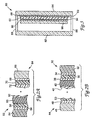
- FIG. 1A there is shown an electrochromic device 10 featuring a flexible tape 12 (minus the release layer) affixed to a rigid substrate 14.
- the tape is shown partially peeled away from the rigid substrate to better illustrate the construction of device 10.
- device 10 is connected to a power supply of conventional design using well-known connecting means.
- Fig. 1 B is an expanded cross-sectional view illustrating the construction of device 10.
- tape 12 features a flexible substrate 16 provided with a transparent electronic conductor 18, an ion-storage material 20, and an ion-conducting electrolyte 22.
- Flexible substrate 16 is preferably a plastic film such as polyethylene terephthalate or polycarbonate.
- the transparent electronic conductor 18 preferably is indium-tin oxide (ITO) or a thin layer of a metallic material such as gold or platinum.
- ITO indium-tin oxide
- flexible, plastic films provided with a transparent conductor are well-known and commercially available, for example, from Southwall Technologies, Inc. of Palo Alto, CA.
- lon-storage material 20 is an ion-intercalating material that stores ions (for example, hydrogen or metal ions such as lithium ions) and then, in response to an applied electrical potential, releases the ions for intercalation into electrochromic material 28.
- ions for example, hydrogen or metal ions such as lithium ions
- Suitable ion-intercalating materials for this purpose are well-known and include electrochromic, weakly electrochromic, and non-electrochromic materials. Examples include group V metal oxides (for example, niobium and vanadium oxides), group VI metal oxides (for example, tungsten and molybdenum oxides), and group VIII metal oxides (for example, nickel, cobalt, iridium, and rhodium oxides).
- the preferred material is V 2 O 5 .
- Ion-conducting electrolyte 22 preferably is a polymer electrolyte having the properties of a pressure sensitive adhesive, although other types of adhesives (for example, hot melt adhesives, in which the adhesive property manifests itself at elevated temperatures) can also be used.
- the electrolyte secures tape 12 to rigid substrate 14. It also conducts ions between ion-storage material 20 and electrochromic material 28 in response an applied electrical potential. The electronic conductivity of the material, however, is minimized in order to avoid shorting out the device.
- a thin (c.a. 500 angstrom) barrier layer may be provided between the electrolyte and the ion-storage material to isolate the electrolyte from the ion-storage material, and thereby extend the lifetime of the device.
- suitable barrier layer materials include tungsten oxide, nickel oxide, and niobium oxide.
- a particularly preferred material for electrolyte 22 is the crosslinked polymerization product of thiol and ene monomers prepared in a solvent-free process using ultraviolet radiation.
- polymers such as polysiloxanes and siloxane copolymers (for example, high molecular weight polysiloxanes having a molecular weight of at least 20,000), polyalkylene oxides (for example, polyethylene oxide), polyacrylates, polyvinyl alcohol, polyvinyl acetal, polyvinyl acetate, and poly-2-acrylamide-2-methyl-propane sulfonic acid (“polyAMPS”), as well as copolymers thereof.
- the polymers if desired, may be swollen with solvent or combined with tackifiers in order to increase the tackiness of the polymer or modify the ionic conductivity.
- Rigid substrate 14 forms the second half of device 10. It features a rigid material 24 such as glass or plastic (for example, a clear plastic such as polycarbonate or polymethyl methacrylate) provided with a transparent electronic conductor 26. Both glass and plastic materials provided with transparent electronic conductors are well-known and commercially available, for example, from Libbey-Owens-Ford Co. of Ottawa, IL in the case of glass materials.
- Rigid substrate 14 further includes an electrochromic material 28 whose optical properties change upon application of an electrical potential.
- Electrochromic materials are well-known and include metallic oxides or combinations of oxides of group IV, V, VI, and VIII metals.
- the electrochromic material can be selected from the class consisting of metal oxyhalides, sulfides, tungstates, molybdates, stannates, vanadates, chromates, titanates, selenides, and tellurides.
- the preferred electrochromic material is WO 3 .
- a tape 30 features a flexible plastic substrate 32 provided with a transparent conductor 34, an ion-storage material 36, a thin barrier layer 38, and a pressure sensitive polymeric ion-conducting electrolyte 40.
- a release layer 42 is provided over the surface of electrolyte 40.
- the release layer which protects the underlying adhesive, is removed prior to laminating tape 30 to a rigid substrate 44 featuring a glass or plastic substrate 46 provided with a transparent conductor 48 and an electrochromic material 50.
- the release layer may be provided in the form of a low surface energy coating to the free surface of flexible substrate 32 (that is, the surface opposite to the surface bearing transparent conductor 34), in which case it is not removed prior to lamination.
- a second way of assembling the device involves using a tape 52 having a flexible plastic substrate 54 provided with a transparent conductor 56, an electrochromic material 58, and a pressure sensitive polymeric ion-conducting electrolyte 60.
- a release layer 62 is provided over the surface of electrolyte 60.
- Tape 52 is laminated to rigid substrate 64 that includes a glass or plastic substrate 66 provided with a transparent conductor 68, an ion-storage material 70, and a barrier film 72.
- the ion-storage material and electrochromic material are deposited on their respective substrates according to conventional techniques, including sputtering.
- WO 3 deposited on glass substrates
- the preferred process is described in a commonly assigned U.S. patent application bearing Attorney Docket No. 52512USA7A, U.S. Serial Number 08/639,020, filed April 24, 1996.
- an initial polytungstate solution preferably an acidified ammonium metatungstate solution
- peroxide to form a peroxypolytungstate solution.
- the peroxypolytungstate solution is converted to a stable oxide polytungstate solution, preferably by (i) drying the peroxypolytungstate solution to form a powder; (ii) dissolving or dispersing the powder in an alcoholic solvent (for example, ethanol), and (iii) heating the alcoholic solution.
- the stable oxide polytungstate solution is then transformed to tungsten oxide, for example, by coating the solution onto a substrate, drying the coated solution to form a residue, and then heating the residue at a temperature ranging from about 100°C to about 350°C.
- the polymeric electrolyte may be coated onto the tape surface in the form of polymerizable monomer(s) or a prepolymer syrup, after which the tape is laminated to the rigid substrate and the monomer(s) or syrup cured, for example, by exposure to ultraviolet radiation to generate the adhesive in situ; curing may also be accomplished prior to lamination.
- the electrolyte may also be applied to the tape surface in the form of an adhesive polymer using conventional techniques, for example, knife coating, roll coating, or extrusion coating, after which the tape is laminated to the rigid substrate.
- Electrochemical devices prepared using the above-described tapes may be incorporated into a glazing unit such as a window, as shown in Fig. 3.
- Glazing unit 80 features a pair of rigid transparent substrates (for example, glass or plastic panes) 82, 84 maintained apart from each other by means of seals 86. The gap between substrates 82, 84 defines a thermal break that provides insulating properties to the glazing unit.
- One of the substrates (shown in Fig. 3 as substrate 84) is provided with a transparent conductor 88 and supports an electrochromic device featuring an electrochromic material 90 (for example, WO 3 ) and an ion-storage material 94 (for example, V 2 O 5 ) separated by a polymeric electrolyte 92.
- a flexible plastic substrate 98 provided with a transparent conductor 96 overlays the electrochromic device to complete the construction.
- the electrochromic device is connected to a power supply of conventional design using well-known connecting means (not shown).
- the glazing unit is prepared according to the method described above by providing substrate 84 (having transparent conductor 88) with electrochromic material 90 and then laminating a tape featuring flexible substrate 98, transparent conductor 96, ion-storage material 94, and polymeric electrolyte 92 to the electrochromic material.
- the polymeric electrolyte may be provided on the surface of the electrochromic material, rather than incorporated in the tape.
- the tape is provided with the electrochromic material, rather than the ion-storage material.
- ammonium metatungstate powder (Pfaltz & Bauer, Waterbury, CT) was dissolved in about 100 g of distilled, de-ionized water.
- a cylindrical, gravity-fed ion exchange column (60 cm long with a 4 cm inner diameter) was filled with 90 cm 3 of AMBERLITE IR 120+ acidic ion exchange resin (Aldrich Chemical, Milwaukee, WI).
- the aqueous ammonium metatungstate solution was then added to the column, and drained through the column at a rate of about 50-70 cm 3 per minute.
- pH of the effluent rapidly changed from neutral to highly acidic (that is, having a pH ⁇ 2), collection began.
- the total amount of material collected was about 130 mLs.
- FTO-coated glass plates (Libbey-Owens-Ford, Toledo, OH) were dipped into a beaker containing the stable oxide polytungstate solution and withdrawn at a rate of about 20 cm per minute. The coated samples were then air-dried, after which they were heat-treated at about 225°C for about 20 minutes in a box furnace to form an electrochromic tungsten oxide coating. Based upon the weight gain of a sample having a known surface area, the average coating thickness was calculated to be approximately 3000 angstroms, assuming a density of about 5.0 g/cm 3 for the amorphous tungsten oxide coating.
- the laminator consisted of a movable table (46 cm X 23 cm) equipped with restraining bars and a 5.1 cm diameter X 23 cm long rubber-covered roller, which was adjusted to apply approximately 5.5x10 4 Pascals (8 psi) pressure to the laminate and an electric motor to power the roller across the table at a rate of approximately 300 cm/minute.
- Electrochemical cells were prepared as follows: A WO 3 -coated glass plate was scribed along one edge to form an electrically-separate FTO section and residual WO 3 was removed from this section. The plate was then positioned on the table of the laminator, its position being maintained by the restraining bars. A copper foil backed pressure sensitive tape having a conductive adhesive (ScotchTM No. 1182, available from 3M Co., St. Paul, MN) was laminated to an uncoated ITO portion of the polymer electrolyte coated flexible electrode to afford connection to the electrode.
- ScotchTM No. 1182 available from 3M Co., St. Paul, MN
- the coated flexible electrode was adhered to one edge of the WO 3 coated glass electrode such that the Cu buss bar was aligned with or in contact with the separate FTO section and the roller of the laminator placed over that portion of the coated flexible electrode. The roller was then activated to laminate the remaining portion of the coated flexible electrode/buss bar assembly to the glass plate to form an electrochromic device.
- the electrochemical test apparatus consisted of a scanning potentiostat (Model 100B, available from Bioanalytical Systems, West Lafayette, IN or Model 362, available from EG&G PARC, Princeton, NJ), a 3 electrode cell containing the test electrode, a Ag/AgCl reference electrode, and a Pt auxiliary electrode, and a test solution of 0.1 N CF 3 SO 3 Li (lithium triflate, available as FC-122 from 3M Co.) (or lithium trifluoromethanesulfonylimide, available as HQ-115 from 3M) in acetonitrile. Charging and discharging were done at -1.0 and +1.0 volts, respectively.
- Optical transmission of test cells was determined using an integrated optical densitometer featuring a quartz halogen lamp Type 2604-A equipped with a blue filter (Photographic Type 80-A) as a light source that corrects temperature to approximate day light.
- the detector was a crystalline silicon photodiode (NCH TR5-5020H).
- ITO indium tin oxide
- PET poly(ethylene terephthalate) film having a 30 ⁇ /sq ITO coating
- the polyethylene glycol 400 diallyl ether was prepared by adding allyl bromide (48.0 g, 0.4 mol, available from Aldrich Chemical Co.) dropwise, to a mixture of polyethylene glycol 400 (80 g, 0.2 mol, available from Dow Chemical, Midland, MI) and sodium hydroxide (10.0 g, 0.25 mol) and the resulting mixture refluxed for 4 hours. After being cooled to room temperature, the reaction mixture was diluted with ether (100 mL) and the precipitate removed by filtration. The filtrate was washed with 5% HCl (100 mL), saturated sodium bicarbonate solution (100 mL), and dried over anhydrous sodium sulfate. Ether was removed form the solution on a rotary evaporator to produce a colorless fluid, the structure of which was confirmed by NMR analysis.
- An approximately 0.13 mm (5 mils) thick coating of the prepolymer syrup was knife coated on the above described flexible electrode and the coating carefully covered with a silicone treated polyester release liner (available from Courtaulds, Canoga Park, CA as Part number 630122A) so as to not disturb the thickness of the prepolymer coating.
- the prepolymer syrup was cured by passing the laminate under a bank of fluorescent lamps (F40T12-350BL lamps commercially available from Osram Sylvania, Danvers, MA), with the release liner surface facing the lamps, for a total residence time of 3 minutes.
- the UV light profile was 330 mJ, 1.5 mW as measured with a UVIMAP Model #UM365H-S photometer (available from EIT Electronic Instrumentation Technology, Inc., Sterling VA). Removal of the release liner exposed a clear, tacky, pressure-sensitive adhesive-like cured "thiol-ene” electrolyte tape. This flexible electrode/electrolyte construction was laminated to the tungsten oxide coated surface of the glass electrode according to the lamination process described above. Cell performance parameters are reported in Table 1 below.
- a "thiol-ene” electrolyte layer was prepared substantially as described in Example 1 except that electrolyte was formed between two pieces of release liner. A 0.13 mm (5 mils) thick coating of the prepolymer syrup was knife coated on the first release liner, the syrup carefully covered by a second release liner, and the laminated structure cured as described in Example 1. After curing, one liner was removed from the "thiol-ene” electrolyte and the electrolyte was heated to 80°C in a dry atmosphere for 24 hours. The electrolyte was subsequently laminated onto the lithiated vanadium oxide surface of a PET film prepared as described in Example 1. The second release liner was removed and the flexible tape laminated onto the tungsten oxide coated surface of the glass electrode described above. Cell performance parameters are reported in Table 1.
- a coated glass electrode was prepared substantially as described above except that an approximately 3800 angstrom thick tungsten oxide ion intercalation layer was ion sputtered over the fluorine doped tin oxide layer of the electrode using standard ion sputtering techniques.
- a flexible tape, prepared as described in Example 1, was laminated to the thus prepared glass substrate to form an electrochromic cell. Cell performance parameters are reported in Table 1.
- a series of four polymer electrolyte films were prepared according to the procedure of Example 1 except that the polymer matrix for all four samples was based on a reaction mixture consisting of triethylene glycol divinyl ether (DVE-3, 1.980 g, 9.85 mmol, available from Aldrich Chemical, Milwaukee, WI), 1,8-dimercapto-4,6-dioxooctane (1.732 g, 9.5 mmol, available from Nisso Maruzen Chemical, Tokyo, Japan), triallyl cyanurate (0.025 g, 0.1 mmol, available from Aldrich Chemical), and 2,2-dimethoxy-2-phenyl acetophenone (KB-1, 4 mg).
- DVE-3 triethylene glycol divinyl ether
- 1,8-dimercapto-4,6-dioxooctane 1.732 g, 9.5 mmol, available from Nisso Maruzen Chemical, Tokyo, Japan
- triallyl cyanurate 0.025
- the concentration of lithium trifluoromethanesulfonate was systematically increased over the range indicated in Table 2 to provide a range of Li/(O+S) ratios, also indicated in Table 2.
- Cells were constructed with each polymer electrolyte film by laminating the film between two circular polished stainless steel electrodes, mounting the thus formed cells in aluminum cans with springs, and hermetically sealing the can.
- a series of polymer electrolyte films were prepared according to the procedure of Example 4 except that the Li/(O+S) ratio was held constant at 1/20 and the crosslinker level was systematically varied from 0.2% to 2.0%, where the crosslinker level was defined as (meq triallyl cyanurate/meq dithiol) X 100%. These preparations were carried out at a X-linker level of the preparations described in Example 4. Actual weights and molar equivalents of the triallyl cyanurate used in the various samples is indicated in Table 4.
- a high molecular weight (MW >20,000) polysiloxane electrolyte was prepared by a condensation reaction of a polyethylene glycol and bis-(dimethylamino)diethyl silane.
- Polyethylene glycol 400 (21.2 g, 0.053 mol, available from Aldrich Chemical, Milwaukee, WI) was dissolved in toluene (80 mL) and the solution heated to 90°C under a dry nitrogen atmosphere.
- Bis -(dimethylamino)diethyl silane (9.7 g, 0.056 mol, available from Gelest, Inc., Tullytown, PA) was added dropwise, with stirring, to polyethylene glycol solution over a period of 4 hours.
- a lightly cross-linked high molecular weight (MW >20,000) polysiloxane electrolyte was prepared using a reaction similar to that described in Example 7.
- Polyethylene glycol 400 (21.2 g, 0.053 mol) was dissolved in toluene (80 ml) and the resulting solution heated to 90°C under a dry nitrogen atmosphere.
- a mixture of bis-(dimethylamino)diethyl silane (9.7 g, 0.056 mol) and bi s-(dimethylamino)ethyl vinyl silane (1.0 g, 0.006 mol, available from Gelest) were added dropwise, with stirring, to the polyethylene glycol solution over 4 hours.
- the polysiloxane electrolyte was crosslinked by irradiating the sample with UV light as described in Example 2 (330 mJ, 1.5 mW).
- the release liner was removed and the flexible tape laminated onto a WO 3 -coated glass electrode as described in Example 1.
- Cell performance parameters are reported in Table 1.
Description
- This invention relates to manufacturing electrochromic devices.
- Electrochromic materials undergo a color change upon oxidation or reduction. In an ion-intercalation electrochromic device, an electrochromic material and an ion-storage counterelectrode material are separated by an ion-conducting electrolyte. The optical properties of the electrochromic material change when ions (for example, hydrogen ions or metal ions such as lithium ions) intercalated within the structure of the ion-storage material are removed and intercalated within the structure of the electrochromic material in response to an applied electrical potential. The ions are removed and returned to the ion-storage material by reversing the polarity of the applied potential, thereby returning the electrochromic material to its original optical state.
- US-5,080,470 discloses a process for manufacturing a light-modulating device comprising a picture element, the process comprising steps of applying a layer of electrolytic material, and then applying a layer of counter-electrode material divided into portions of a layer defined and distributed according to a surface pattern co-ordinated with a surface pattern of transparent electrodes.
- NITS Tech Notes, 1. Juli 1992, page 480/481 XP 000308040 "Electrochromatic Optical Switching Device", discloses an electrochromic device comprising an ion-intercalating electrochromic material and an ion-intercalating ion-storage material separated by an ion-conducting electrolyte and disposed between two electronically conductive substrates.
- In a first aspect, the invention features a tape as defined in
claim 1 that includes among other things an electronically conductive flexible substrate, a release layer (which may be continuous or discontinuous), and an adhesive that includes an ion-intercalating material. An "adhesive" includes both single and multi-layer constructions that display adhesive properties at ambient conditions or develop such properties, for example, upon swelling with solvent or exposure to elevated temperature. The "adhesive" includes embodiments where the ion-intercalating material itself displays adhesive properties, as well as constructions where the ion-intercalating material is combined with one or more additional materials (for example, in the form of separate layers or admixed with the ion-intercalating material), with the net result that the aggregate construction displays adhesive properties. - An "ion-intercalating" material is a material whose microstructure is configured such that ions (for example, hydrogen or metal ions such as lithium ions) can be reversibly intercalated into the material in response to an applied electrical potential.
- In one preferred embodiment, the ion-intercalating material is disposed between the substrate and the release layer. In another preferred embodiment, the release layer is a low surface energy coating provided on one surface of the substrate, the ion-intercalating material being provided on the opposing surface of the substrate.
- Preferably, the adhesive is a pressure sensitive adhesive. Examples of preferred adhesive constructions include electrochromic materials (for example, WO3), which may further be provided with an ion-conducting polymer electrolyte. As used herein, "electrochromic material" refers to materials both with and without intercalated ions. Thus, for example, in the case of WO3, it includes both WO3 and MxWO3, where M is an intercalated hydrogen or metal ion. Another preferred adhesive construction includes ion-storage materials (for example, V2O5), which may further be provided with an ion-conducting polymer electrolyte.
- One example of a preferred construction is one in which the electrochromic or ion-storage material itself is not adhesive, but the polymer electrolyte is. The aggregate construction (electrochromic or ion-storage material plus polymer electrolyte) thus constitutes the "adhesive."
- One preferred flexible substrate includes polyethylene terephthalate provided with a transparent conductor. The flexible substrate may also be reflective. For example, it may include a layer of a reflective material such as silver.
- The invention further features a method of assembling an electrochromic device as defined in claim 9 using the above-described tapes that includes contacting a second electronically conductive substrate with the adhesive portion of the tape, and then laminating the tape and the second electronically conductive substrate together. Preferably, the second substrate includes a rigid material such as glass provided with a transparent conductor.
- In the case of embodiments in which the tape includes an electrochromic material such as WO3 and an ion-conducting polymer electrolyte, the second substrate preferably includes an ion-storage material such as V2O5. Conversely, in the case of embodiments in which the tape includes an ion-storage material such as V2O5 and an ion-conducting polymer electrolyte, the second substrate preferably includes an electrochromic material such as WO3.
- Flexible tapes according to the invention offer several advantages over existing materials in the manufacture of electrochromic devices. For example, because the tapes are flexible, they can be provided in the form of rolls and dispensed in the appropriate size when needed. The tapes are thus suitable for mass production of large area devices (for example, light modulating devices).
- The combination of rigid and flexible substrates in the case of devices featuring, for example, electrochromic and ion-storage materials separated by an ion-conducting electrolyte is advantageous as well. The rigid substrate facilitates the deposition of the electrochromic material, leading to higher quality electrochromic material. The flexible substrate is easier to laminate to the rigid substrate compared to another rigid substrate, resulting in fewer defects such as air bubbles; such defects can compromise the electrical and optical properties of the device. The flexible substrate also provides the manufacturing advantages described above.
- Other features and advantages of the invention will be apparent from the following description of the preferred embodiments thereof, and from the claims.
-
- Fig. 1 A is a perspective view of an electrochromic device featuring a pair of flexible and rigid substrates partially separated from each other.
- Fig. 1 B is an expanded cross-sectional view of the device shown in Fig. 1A.
- Figs. 2A and 2B are schematic drawings illustrating two methods of assembling an electrochromic device using tapes according to the invention.
- Fig. 3 is a cross-sectional view of a glazing unit
- Fig. 4 is an Arrhenius plot showing conductivity of various electrolyte compositions as a function of lithium to (oxygen plus sulfur) ratio.
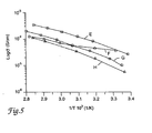
- Fig. 5 is an Arrhenius plot showing conductivity of various electrolyte compositions as a function of type of lithium salt.
- Fig. 6 is an Arrhenius plot showing conductivity of various electrolyte compositions as a function of crosslinking level.
- Referring to Fig. 1A, there is shown an
electrochromic device 10 featuring a flexible tape 12 (minus the release layer) affixed to arigid substrate 14. The tape is shown partially peeled away from the rigid substrate to better illustrate the construction ofdevice 10. In use,device 10 is connected to a power supply of conventional design using well-known connecting means. - Fig. 1 B is an expanded cross-sectional view illustrating the construction of
device 10. As shown in the figure,tape 12 features aflexible substrate 16 provided with a transparentelectronic conductor 18, an ion-storage material 20, and an ion-conductingelectrolyte 22.Flexible substrate 16 is preferably a plastic film such as polyethylene terephthalate or polycarbonate. The transparentelectronic conductor 18 preferably is indium-tin oxide (ITO) or a thin layer of a metallic material such as gold or platinum. Flexible, plastic films provided with a transparent conductor are well-known and commercially available, for example, from Southwall Technologies, Inc. of Palo Alto, CA. - lon-
storage material 20 is an ion-intercalating material that stores ions (for example, hydrogen or metal ions such as lithium ions) and then, in response to an applied electrical potential, releases the ions for intercalation intoelectrochromic material 28. Suitable ion-intercalating materials for this purpose are well-known and include electrochromic, weakly electrochromic, and non-electrochromic materials. Examples include group V metal oxides (for example, niobium and vanadium oxides), group VI metal oxides (for example, tungsten and molybdenum oxides), and group VIII metal oxides (for example, nickel, cobalt, iridium, and rhodium oxides). The preferred material is V2O5. - Ion-conducting
electrolyte 22 preferably is a polymer electrolyte having the properties of a pressure sensitive adhesive, although other types of adhesives (for example, hot melt adhesives, in which the adhesive property manifests itself at elevated temperatures) can also be used. The electrolyte secures tape 12 torigid substrate 14. It also conducts ions between ion-storage material 20 andelectrochromic material 28 in response an applied electrical potential. The electronic conductivity of the material, however, is minimized in order to avoid shorting out the device. - A thin (c.a. 500 angstrom) barrier layer (not shown) may be provided between the electrolyte and the ion-storage material to isolate the electrolyte from the ion-storage material, and thereby extend the lifetime of the device. Examples of suitable barrier layer materials are well-known and include tungsten oxide, nickel oxide, and niobium oxide.
- A particularly preferred material for
electrolyte 22 is the crosslinked polymerization product of thiol and ene monomers prepared in a solvent-free process using ultraviolet radiation. Also suitable are polymers such as polysiloxanes and siloxane copolymers (for example, high molecular weight polysiloxanes having a molecular weight of at least 20,000), polyalkylene oxides (for example, polyethylene oxide), polyacrylates, polyvinyl alcohol, polyvinyl acetal, polyvinyl acetate, and poly-2-acrylamide-2-methyl-propane sulfonic acid ("polyAMPS"), as well as copolymers thereof. The polymers, if desired, may be swollen with solvent or combined with tackifiers in order to increase the tackiness of the polymer or modify the ionic conductivity. -
Rigid substrate 14 forms the second half ofdevice 10. It features arigid material 24 such as glass or plastic (for example, a clear plastic such as polycarbonate or polymethyl methacrylate) provided with a transparentelectronic conductor 26. Both glass and plastic materials provided with transparent electronic conductors are well-known and commercially available, for example, from Libbey-Owens-Ford Co. of Ottawa, IL in the case of glass materials. -
Rigid substrate 14 further includes anelectrochromic material 28 whose optical properties change upon application of an electrical potential. Electrochromic materials are well-known and include metallic oxides or combinations of oxides of group IV, V, VI, and VIII metals. In particular, the electrochromic material can be selected from the class consisting of metal oxyhalides, sulfides, tungstates, molybdates, stannates, vanadates, chromates, titanates, selenides, and tellurides. The preferred electrochromic material is WO3. - Fig. 2b schematically illustrates the preparation of an electrochromic device using tapes according to the invention. In one embodiment, a
tape 30 features a flexibleplastic substrate 32 provided with atransparent conductor 34, an ion-storage material 36, a thin barrier layer 38, and a pressure sensitive polymeric ion-conductingelectrolyte 40. Arelease layer 42 is provided over the surface ofelectrolyte 40. The release layer, which protects the underlying adhesive, is removed prior to laminatingtape 30 to arigid substrate 44 featuring a glass orplastic substrate 46 provided with atransparent conductor 48 and anelectrochromic material 50. Alternatively, the release layer may be provided in the form of a low surface energy coating to the free surface of flexible substrate 32 (that is, the surface opposite to the surface bearing transparent conductor 34), in which case it is not removed prior to lamination. - A second way of assembling the device (shown in Fig. 2a) involves using a
tape 52 having a flexibleplastic substrate 54 provided with atransparent conductor 56, anelectrochromic material 58, and a pressure sensitive polymeric ion-conductingelectrolyte 60. Arelease layer 62 is provided over the surface ofelectrolyte 60. As in the case oftape 30, described above, a low surface energy coating may be applied to the free side ofsubstrate 54 in lieu ofrelease layer 62.Tape 52 is laminated torigid substrate 64 that includes a glass orplastic substrate 66 provided with atransparent conductor 68, an ion-storage material 70, and abarrier film 72. - The ion-storage material and electrochromic material are deposited on their respective substrates according to conventional techniques, including sputtering. In the case of WO3 deposited on glass substrates, the preferred process is described in a commonly assigned U.S. patent application bearing Attorney Docket No. 52512USA7A, U.S. Serial Number 08/639,020, filed April 24, 1996.. According to this process, an initial polytungstate solution (preferably an acidified ammonium metatungstate solution) is treated with peroxide to form a peroxypolytungstate solution. The peroxypolytungstate solution is converted to a stable oxide polytungstate solution, preferably by (i) drying the peroxypolytungstate solution to form a powder; (ii) dissolving or dispersing the powder in an alcoholic solvent (for example, ethanol), and (iii) heating the alcoholic solution. The stable oxide polytungstate solution is then transformed to tungsten oxide, for example, by coating the solution onto a substrate, drying the coated solution to form a residue, and then heating the residue at a temperature ranging from about 100°C to about 350°C.
- The polymeric electrolyte may be coated onto the tape surface in the form of polymerizable monomer(s) or a prepolymer syrup, after which the tape is laminated to the rigid substrate and the monomer(s) or syrup cured, for example, by exposure to ultraviolet radiation to generate the adhesive in situ; curing may also be accomplished prior to lamination. The electrolyte may also be applied to the tape surface in the form of an adhesive polymer using conventional techniques, for example, knife coating, roll coating, or extrusion coating, after which the tape is laminated to the rigid substrate.
- Electrochemical devices prepared using the above-described tapes may be incorporated into a glazing unit such as a window, as shown in Fig. 3.
Glazing unit 80 features a pair of rigid transparent substrates (for example, glass or plastic panes) 82, 84 maintained apart from each other by means ofseals 86. The gap betweensubstrates - One of the substrates (shown in Fig. 3 as substrate 84) is provided with a
transparent conductor 88 and supports an electrochromic device featuring an electrochromic material 90 (for example, WO3) and an ion-storage material 94 (for example, V2O5) separated by apolymeric electrolyte 92. A flexibleplastic substrate 98 provided with atransparent conductor 96 overlays the electrochromic device to complete the construction. In use, the electrochromic device is connected to a power supply of conventional design using well-known connecting means (not shown). - The glazing unit is prepared according to the method described above by providing substrate 84 (having transparent conductor 88) with
electrochromic material 90 and then laminating a tape featuringflexible substrate 98,transparent conductor 96, ion-storage material 94, andpolymeric electrolyte 92 to the electrochromic material. Alternatively, the polymeric electrolyte may be provided on the surface of the electrochromic material, rather than incorporated in the tape. In yet another alternative, the tape is provided with the electrochromic material, rather than the ion-storage material. - The invention will now be described further by way of the following examples.
- About 20 g of 99.9%+ ammonium metatungstate powder (Pfaltz & Bauer, Waterbury, CT) was dissolved in about 100 g of distilled, de-ionized water. A cylindrical, gravity-fed ion exchange column (60 cm long with a 4 cm inner diameter) was filled with 90 cm3 of AMBERLITE IR 120+ acidic ion exchange resin (Aldrich Chemical, Milwaukee, WI). The aqueous ammonium metatungstate solution was then added to the column, and drained through the column at a rate of about 50-70 cm3 per minute. When the pH of the effluent rapidly changed from neutral to highly acidic (that is, having a pH < 2), collection began. The total amount of material collected was about 130 mLs.
- Next, about 10 g of 30% hydrogen peroxide (Mallinckrodt Chemical Co., Paris, KY) was added to the acidified ammonium metatungstate solution collected from the ion exchange column, and the resulting solution stirred for 30 minutes. The solution was then dried on a rotary evaporator at 40°C to a non-tacky solid in about 45 minutes. About 90 mL of absolute ethanol was added to the dried powder, after which the mixture was stirred at about 60°C for about 1 hour until the powder had dissolved. About 5 mL of distilled, de-ionized water was then added to the ethanol solution, followed by refluxing at the boiling point (about 77°C) for about 90 minutes. The resulting stable oxide polytungstate solution contained about 17% by weight tungsten oxide and had a room temperature viscosity of about 2.5 centistokes.
- FTO-coated glass plates (Libbey-Owens-Ford, Toledo, OH) were dipped into a beaker containing the stable oxide polytungstate solution and withdrawn at a rate of about 20 cm per minute. The coated samples were then air-dried, after which they were heat-treated at about 225°C for about 20 minutes in a box furnace to form an electrochromic tungsten oxide coating. Based upon the weight gain of a sample having a known surface area, the average coating thickness was calculated to be approximately 3000 angstroms, assuming a density of about 5.0 g/cm3 for the amorphous tungsten oxide coating.
- Samples were tested using the electrochemical test method described below with a lithium triflate/acetonitrile electrolyte solution.
- The laminator consisted of a movable table (46 cm X 23 cm) equipped with restraining bars and a 5.1 cm diameter X 23 cm long rubber-covered roller, which was adjusted to apply approximately 5.5x10⁴ Pascals (8 psi) pressure to the laminate and an electric motor to power the roller across the table at a rate of approximately 300 cm/minute.
- Electrochemical cells were prepared as follows: A WO3-coated glass plate was scribed along one edge to form an electrically-separate FTO section and residual WO3 was removed from this section. The plate was then positioned on the table of the laminator, its position being maintained by the restraining bars. A copper foil backed pressure sensitive tape having a conductive adhesive (Scotch™ No. 1182, available from 3M Co., St. Paul, MN) was laminated to an uncoated ITO portion of the polymer electrolyte coated flexible electrode to afford connection to the electrode. The coated flexible electrode was adhered to one edge of the WO3 coated glass electrode such that the Cu buss bar was aligned with or in contact with the separate FTO section and the roller of the laminator placed over that portion of the coated flexible electrode. The roller was then activated to laminate the remaining portion of the coated flexible electrode/buss bar assembly to the glass plate to form an electrochromic device.
- The electrochemical test apparatus consisted of a scanning potentiostat (Model 100B, available from Bioanalytical Systems, West Lafayette, IN or Model 362, available from EG&G PARC, Princeton, NJ), a 3 electrode cell containing the test electrode, a Ag/AgCl reference electrode, and a Pt auxiliary electrode, and a test solution of 0.1 N CF3SO3Li (lithium triflate, available as FC-122 from 3M Co.) (or lithium trifluoromethanesulfonylimide, available as HQ-115 from 3M) in acetonitrile. Charging and discharging were done at -1.0 and +1.0 volts, respectively.
- Optical transmission of test cells was determined using an integrated optical densitometer featuring a quartz halogen lamp Type 2604-A equipped with a blue filter (Photographic Type 80-A) as a light source that corrects temperature to approximate day light. The detector was a crystalline silicon photodiode (NCH TR5-5020H).
- The indium tin oxide (ITO) surface of a 0.18 mm (7 mils) thick poly(ethylene terephthalate) film (PET) having a 30 Ω /sq ITO coating (available from Southwall Technologies Inc., Palo Alto, CA) was sputter coated with a 180 nm thick vanadium oxide layer followed by a 10 nm thick tungsten oxide layer. (Both the vanadium oxide and tungsten oxide layers were applied by DC magnetron sputtering at 6 kW, 0.8 Pa and an argon to oxygen ratio of 4.) The thus produced layered structure was converted to lithiated vanadium oxide by electrochemical reduction methods in a 0.1 M lithium triflate solution in acetonitrile using a voltage of -1.0 V relative to a silver chloride reference electrode. The reduced electrode was rinsed in acetonitrile and dried in a vacuum (< 1 mm Hg) at room temperature.
- A mixture of 1,8-dimercapto-4,7-dioxooctane (1.73 g, 9.5 mmole, available from Nisso Maruzen Chemical, Tokyo, Japan), polyethylene glycol 400 diallyl ether (5.160 g, 10 mmole, prepared as described below), poly(3-mercaptopropyl)methyldisiloxane (0.067 g, 0.5 mmole, available from United Chemicals Technologies, Inc., Bristol, PA), 2,2-dimethoxy-2-phenyl acetophenone (7 mg, available as KB-1 from Sartomer Chemical, Exton, PA), and lithium trifluoromethanesulfonylimide (2.30 g, 8 mmol, available from 3M, St. Paul, MN) was shaken in a sealed glass bottle until all of the reactants had dissolved (approximately 2 hours). The resulting solution was irradiated with black light (λmax 365nm) for approximately 20 seconds to obtain a coatable prepolymer syrup.
- The polyethylene glycol 400 diallyl ether was prepared by adding allyl bromide (48.0 g, 0.4 mol, available from Aldrich Chemical Co.) dropwise, to a mixture of polyethylene glycol 400 (80 g, 0.2 mol, available from Dow Chemical, Midland, MI) and sodium hydroxide (10.0 g, 0.25 mol) and the resulting mixture refluxed for 4 hours. After being cooled to room temperature, the reaction mixture was diluted with ether (100 mL) and the precipitate removed by filtration. The filtrate was washed with 5% HCl (100 mL), saturated sodium bicarbonate solution (100 mL), and dried over anhydrous sodium sulfate. Ether was removed form the solution on a rotary evaporator to produce a colorless fluid, the structure of which was confirmed by NMR analysis.
- An approximately 0.13 mm (5 mils) thick coating of the prepolymer syrup was knife coated on the above described flexible electrode and the coating carefully covered with a silicone treated polyester release liner (available from Courtaulds, Canoga Park, CA as Part number 630122A) so as to not disturb the thickness of the prepolymer coating. The prepolymer syrup was cured by passing the laminate under a bank of fluorescent lamps (F40T12-350BL lamps commercially available from Osram Sylvania, Danvers, MA), with the release liner surface facing the lamps, for a total residence time of 3 minutes. The UV light profile was 330 mJ, 1.5 mW as measured with a UVIMAP Model #UM365H-S photometer (available from EIT Electronic Instrumentation Technology, Inc., Sterling VA). Removal of the release liner exposed a clear, tacky, pressure-sensitive adhesive-like cured "thiol-ene" electrolyte tape. This flexible electrode/electrolyte construction was laminated to the tungsten oxide coated surface of the glass electrode according to the lamination process described above. Cell performance parameters are reported in Table 1 below.
Table 1 Example Color dark Color bleach Dynamic range percent transmission Charge density #Cycles Decay Current density Voltage # 1 blue taupe 12% to 45% 20mC/cm2 10,000 None ».15mA/cm2 -/+2.5 #2 blue taupe 10-15% to 40-50% >15mC/cm2 >103 None ».15mA/cm2 -/+2.5 #3 blue taupe 10-15% to 40-50% >15mC/cm2 >103 None ».15mA/cm2 -/+2.5 #7 blue taupe 10-15% to 40-50% >15mC/cm2 >103 None ».15mA/cm2 -/+2.5 #8 blue taupe 10-15% to 40-50% >15mC/cm2 >103 None ».15mA/cm2 -/+2.5 - A "thiol-ene" electrolyte layer was prepared substantially as described in Example 1 except that electrolyte was formed between two pieces of release liner. A 0.13 mm (5 mils) thick coating of the prepolymer syrup was knife coated on the first release liner, the syrup carefully covered by a second release liner, and the laminated structure cured as described in Example 1. After curing, one liner was removed from the "thiol-ene" electrolyte and the electrolyte was heated to 80°C in a dry atmosphere for 24 hours. The electrolyte was subsequently laminated onto the lithiated vanadium oxide surface of a PET film prepared as described in Example 1. The second release liner was removed and the flexible tape laminated onto the tungsten oxide coated surface of the glass electrode described above. Cell performance parameters are reported in Table 1.
- A coated glass electrode was prepared substantially as described above except that an approximately 3800 angstrom thick tungsten oxide ion intercalation layer was ion sputtered over the fluorine doped tin oxide layer of the electrode using standard ion sputtering techniques. A flexible tape, prepared as described in Example 1, was laminated to the thus prepared glass substrate to form an electrochromic cell. Cell performance parameters are reported in Table 1.
- A series of four polymer electrolyte films were prepared according to the procedure of Example 1 except that the polymer matrix for all four samples was based on a reaction mixture consisting of triethylene glycol divinyl ether (DVE-3, 1.980 g, 9.85 mmol, available from Aldrich Chemical, Milwaukee, WI), 1,8-dimercapto-4,6-dioxooctane (1.732 g, 9.5 mmol, available from Nisso Maruzen Chemical, Tokyo, Japan), triallyl cyanurate (0.025 g, 0.1 mmol, available from Aldrich Chemical), and 2,2-dimethoxy-2-phenyl acetophenone (KB-1, 4 mg). The concentration of lithium trifluoromethanesulfonate was systematically increased over the range indicated in Table 2 to provide a range of Li/(O+S) ratios, also indicated in Table 2. Cells were constructed with each polymer electrolyte film by laminating the film between two circular polished stainless steel electrodes, mounting the thus formed cells in aluminum cans with springs, and hermetically sealing the can.
TABLE 2 Conductivity as a Function of Li/(O+S) Ratio Sample Grams LIN(SO2CF3)2 Mmol LIN(SO2CF3)2 Li/(O+S) Ratio 4a 2.870 10 1/8 4b 2.296 8 1/10 4c 1.148 4 1/20 4d 0.574 2 1/40 - A series of polymer electrolyte films were prepared according to the procedure of Example 4 except that the Li/(O+S) ratio was held constant at 1/20 and four different Li salts were incorporated into the polymer electrolyte formulations as indicated in Table 3.
TABLE 3 Conductivity as a Function of Type of Li Salt Sample Li Salt Gm Salt Mm ol Salt 5a LiN(SO2C F3)2 1 1.148 4 5b LiO3SCF3 1 0.624 4 5c 1 LiO3SC4F91 1.224 4 5d LiClO4 2 0.425 4 1. Available from 3M. 2. Available from Aldrich Chemical. - Arrhenius plots of the data obtained from these studies, which are presented in Figure 5, where curve E corresponds to sample 5a, curve F corresponds to sample 5b, curve G corresponds to sample 5c, and curve H corresponds to sample 5d, demonstrates that the polymer electrolyte films have good conductivity with a range of salts, several of which do not exhibit a plasticizing effect on the polymer electrolyte.
- A series of polymer electrolyte films were prepared according to the procedure of Example 4 except that the Li/(O+S) ratio was held constant at 1/20 and the crosslinker level was systematically varied from 0.2% to 2.0%, where the crosslinker level was defined as (meq triallyl cyanurate/meq dithiol) X 100%. These preparations were carried out at a X-linker level of the preparations described in Example 4. Actual weights and molar equivalents of the triallyl cyanurate used in the various samples is indicated in Table 4.
TABLE 4 Conductivity as a function of Crosslink Density Sample Gm DVE-3 meq DVE-3 Gm Triallyl Cyanurate Mmol Triallyl Cyanurate X-linker Level (%) 6 a 16.128 79.76 19.942 0.06 0.6 6 b 16.080 79.52 39.8844 .12 1.2 6 c 16.032 79.28 59.824 .18 1.8 6 d 15.984 79.04 79.768 .24 2.4 6 e 15.936 78.80 99.708 0.45 3.0 6 f 15.816 79.24 149.564 0.45 4.5 6 g 15.696 77.60 199.416 0.6 6.0 - Arrhenius plots of the data obtained from these studies, which are shown in Figure 6, demonstrate that within the crosslinker range studied, lower crosslinker levels produced higher conductivities in the polymer electrolytes. In Figure 6, curve (I) corresponds to Sample 6a, curve (J) corresponds to Sample 6b, curve (K) corresponds to Sample 6c, curve (L) corresponds to Sample 6d, curve (M) corresponds to Sample 6e, curve (N) corresponds to Sample 6f, and curve (O) corresponds to Sample 6g.
- A high molecular weight (MW >20,000) polysiloxane electrolyte was prepared by a condensation reaction of a polyethylene glycol and bis-(dimethylamino)diethyl silane. Polyethylene glycol 400 (21.2 g, 0.053 mol, available from Aldrich Chemical, Milwaukee, WI) was dissolved in toluene (80 mL) and the solution heated to 90°C under a dry nitrogen atmosphere. Bis-(dimethylamino)diethyl silane (9.7 g, 0.056 mol, available from Gelest, Inc., Tullytown, PA) was added dropwise, with stirring, to polyethylene glycol solution over a period of 4 hours. Heating and stirring were continued for approximately 24 hours, after which a rubbery solid was isolated by adding hexane (approximately 100 mL) to the reaction mixture. The rubber was dried under vacuum (30 mm Hg and 50°C) for approximately 4 hours and a portion of the rubber (4 g) was redissolved in acetonitrile (20 mL) containing lithium triflate (1.5 g, available from 3M Co.). The solvent was evaporated under vacuum (40°C and 30 mm Hg), the dried rubber was placed between a release liner and a flexible PET substrate coated with ITO and lithiated vanadium oxide, as described in Example 1, and the laminate was pressed in a hydraulic press to produce a 0.13 mm (5 mils) thick electrolyte layer. An electrochromic cell was prepared by removing the release liner and laminating the flexible tape to the WO3 coated electrode described above. Cell performance parameters are reported in Table 1.
- A lightly cross-linked high molecular weight (MW >20,000) polysiloxane electrolyte was prepared using a reaction similar to that described in Example 7. Polyethylene glycol 400 (21.2 g, 0.053 mol) was dissolved in toluene (80 ml) and the resulting solution heated to 90°C under a dry nitrogen atmosphere. A mixture of bis-(dimethylamino)diethyl silane (9.7 g, 0.056 mol) and bis-(dimethylamino)ethyl vinyl silane (1.0 g, 0.006 mol, available from Gelest) were added dropwise, with stirring, to the polyethylene glycol solution over 4 hours. Heating and stirring were continued for approximately 24 hours, after which a rubbery solid was isolated by adding hexane (100 mL) to the reaction mixture. The rubber was dried under vacuum (40°C and 30 mm Hg) for approximately 8 hours and a portion of the rubber (4 g) was redissolved in acetonitrile (20 mL) containing lithium triflate (1.5 g). After the solvent was evaporated, the rubber was incorporated into an electrochromic cell as described in Example 7. The solvent was evaporated, the rubber was placed between a release liner and a flexible PET substrate coated with ITO and lithiated vanadium oxide, prepared as described in Example 2, and the laminate was pressed in a hydraulic press to produce a 1.3 mm (5 mils) thick electrolyte layer. The polysiloxane electrolyte was crosslinked by irradiating the sample with UV light as described in Example 2 (330 mJ, 1.5 mW). The release liner was removed and the flexible tape laminated onto a WO3-coated glass electrode as described in Example 1. Cell performance parameters are reported in Table 1.
- Other embodiments are within the following claims.
Claims (13)
- A tape (30,52) comprising an electronically conductive flexible substrate (32, 54) a release element (42,62) selected from the group consisting of removable release layers and low surface energy coatings, and an adhesive portion comprising a first ion-intercalating material (36,58) and an ion-conducting polymeric electrolyte (40,60), being adapted such that when the adhesive portion of said tape is laminated to a second electronically conductive substrate (44,64) comprising a second ion-intercalating material (50, 70) to form an electrochromic device, the device is capable of undergoing a visible change in transmission or reflectance upon application of a voltage, and wherein one of the first and second ion-intercalating materials comprises an electrochromic material and the other ion-intercalating material comprises an ion-storing material (20) .
- A tape according to claim 1 wherein said first ion-intercalating material is disposed between said flexible substrate and said release layer.
- A tape according to claim 1 wherein said release layer comprises a low surface energy coating provided on one face of said flexible substrate, said first ion-intercalating material being provided on the opposing face of said substrate.
- A tape according to claim 1 wherein said adhesive portion comprises a pressure sensitive adhesive.
- A tape according to claim 1 wherein said first ion-intercalating material comprises an electrochromic material.
- A tape according to claim 1 wherein said first ion-intercalating material comprises an ion storage material.
- A tape according to any one of claims 1-6 wherein said flexible substrate comprises polyethylene terephthalate provided with a transparent conductor..
- A tape according to any one of claims 1-6 wherein said flexible substrate comprises a reflective substrate.
- A method of assembling an electrochromic device comprising the steps of:(a) providing a tape (30,52) comprising an electronically conductive flexible substrate (32, 54) a release layer (42,62), and an adhesive portion comprising a first ion-intercalating material (36,58) and an ion-conducting polymeric electrolyte (40,60);(b) contacting a second electronically conductive substrate (44, 64) comprising a second ion-intercalating material (50, 70) with the adhesive portion of said tape,
one of said first and second ion-intercalating materials comprising an electrochromic material and the other of said ion-intercalating materials comprising an ion-storage material; and(c) laminating said tape and said second electronically conductive substrate together. - A method according to claim 9 wherein said second substrate comprises a rigid substrate.
- A method according to claim 9 wherein said first ion-intercalating material comprises an electrochromic material, and said second ion-intercalating material comprises an ion-storage material.
- A method according to claim 9 wherein said first ion-intercalating material comprises an ion-storage material.
- A method according to claim 12 wherein said second ion-intercalating material comprises an electrochromic material.
Applications Claiming Priority (3)
| Application Number | Priority Date | Filing Date | Title |
|---|---|---|---|
| US08/639,019 US5825526A (en) | 1996-04-24 | 1996-04-24 | Tape for use in manufacturing electrochromic devices |
| US639019 | 1996-04-24 | ||
| PCT/US1997/004294 WO1997040419A1 (en) | 1996-04-24 | 1997-03-17 | Tape for use in manufacturing electrochromic devices |
Publications (2)
| Publication Number | Publication Date |
|---|---|
| EP0895611A1 EP0895611A1 (en) | 1999-02-10 |
| EP0895611B1 true EP0895611B1 (en) | 2006-09-06 |
Family
ID=24562401
Family Applications (1)
| Application Number | Title | Priority Date | Filing Date |
|---|---|---|---|
| EP97915147A Expired - Lifetime EP0895611B1 (en) | 1996-04-24 | 1997-03-17 | Tape for use in manufacturing electrochromic devices |
Country Status (6)
| Country | Link |
|---|---|
| US (1) | US5825526A (en) |
| EP (1) | EP0895611B1 (en) |
| JP (1) | JP3972070B2 (en) |
| CA (1) | CA2251720C (en) |
| DE (1) | DE69736632T2 (en) |
| WO (1) | WO1997040419A1 (en) |
Families Citing this family (63)
| Publication number | Priority date | Publication date | Assignee | Title |
|---|---|---|---|---|
| US6825829B1 (en) * | 1997-08-28 | 2004-11-30 | E Ink Corporation | Adhesive backed displays |
| US5995271A (en) * | 1997-10-07 | 1999-11-30 | Optical Coating Laboratory, Inc. | Protective coating materials for electrochromic devices |
| US6539286B1 (en) * | 1998-01-26 | 2003-03-25 | Micron Technology, Inc. | Fluid level sensor |
| US6093451A (en) * | 1998-01-30 | 2000-07-25 | Pilkington Aerospace Inc. | Coated transparencies and transparent laminates incorporating a transparent polyurethane composition |
| US6151153A (en) * | 1998-06-16 | 2000-11-21 | Photon Dynamics, Inc. | Modulator transfer process and assembly |
| US6211991B1 (en) * | 1998-06-16 | 2001-04-03 | Photon Dynamics, Inc. | Modulator manufacturing process and device |
| DE19834834A1 (en) * | 1998-08-01 | 2000-02-03 | Bayer Ag | Self-adhesive electrochromic electrode and arrangements containing it |
| US6144479A (en) * | 1998-12-16 | 2000-11-07 | 3M Innovative Properties Company | Low reflectivity contrast enhancement filter |
| SE521683C2 (en) * | 2000-06-14 | 2003-11-25 | Ivf Industriforskning Och Utve | Method of Manufacture of Sealed Monolithic Electrochemical Systems and Sealed Monolithic Electrochemical System |
| US6639708B2 (en) * | 2001-04-24 | 2003-10-28 | Schott North America, Inc | Electrochromic safety glazing |
| JP3804822B2 (en) * | 2001-06-26 | 2006-08-02 | ソニー株式会社 | Display element and manufacturing method thereof |
| US6982178B2 (en) | 2002-06-10 | 2006-01-03 | E Ink Corporation | Components and methods for use in electro-optic displays |
| US6831769B2 (en) * | 2001-07-09 | 2004-12-14 | E Ink Corporation | Electro-optic display and lamination adhesive |
| US6456418B1 (en) | 2001-09-06 | 2002-09-24 | Chameleon Optics, Inc | Flexible electrochromic devices |
| US7843621B2 (en) | 2002-06-10 | 2010-11-30 | E Ink Corporation | Components and testing methods for use in the production of electro-optic displays |
| US7583427B2 (en) | 2002-06-10 | 2009-09-01 | E Ink Corporation | Components and methods for use in electro-optic displays |
| US8363299B2 (en) | 2002-06-10 | 2013-01-29 | E Ink Corporation | Electro-optic displays, and processes for the production thereof |
| US7110164B2 (en) | 2002-06-10 | 2006-09-19 | E Ink Corporation | Electro-optic displays, and processes for the production thereof |
| US8049947B2 (en) | 2002-06-10 | 2011-11-01 | E Ink Corporation | Components and methods for use in electro-optic displays |
| US9470950B2 (en) | 2002-06-10 | 2016-10-18 | E Ink Corporation | Electro-optic displays, and processes for the production thereof |
| US7839564B2 (en) | 2002-09-03 | 2010-11-23 | E Ink Corporation | Components and methods for use in electro-optic displays |
| EP3056941B1 (en) | 2002-09-03 | 2019-01-09 | E Ink Corporation | Electro-phoretic medium |
| KR100985418B1 (en) * | 2002-11-26 | 2010-10-05 | 이 잉크 코포레이션 | Flexible electronic circuits and displays |
| US20050122563A1 (en) | 2003-07-24 | 2005-06-09 | E Ink Corporation | Electro-optic displays |
| US7638807B2 (en) * | 2003-10-28 | 2009-12-29 | Sumitomo Metal Mining Co., Ltd. | Transparent conductive multi-layer structure, process for its manufacture and device making use of transparent conductive multi-layer structure |
| US7586663B1 (en) * | 2005-03-01 | 2009-09-08 | Triton Systems, Inc. | Gel polymer electrolytes |
| US20080043318A1 (en) | 2005-10-18 | 2008-02-21 | E Ink Corporation | Color electro-optic displays, and processes for the production thereof |
| MX2008012426A (en) * | 2006-03-30 | 2008-12-18 | Rhodia | Modified surfaces and method for modifying a surface. |
| DE102007029066B4 (en) * | 2006-06-21 | 2013-01-03 | Flabeg Gmbh & Co. Kg | Electrically active element |
| US7414771B2 (en) * | 2006-08-03 | 2008-08-19 | Chameleon Optics, Inc. | Adhesive ion-conducting layer for flexible electrochromic devices |
| US7940447B2 (en) * | 2006-12-04 | 2011-05-10 | 3M Innovative Properties Company | Electrochromic device |
| US7764416B2 (en) * | 2006-12-04 | 2010-07-27 | 3M Innovative Properties Company | Electrochromic device based on layer by layer deposition |
| US7864397B2 (en) * | 2006-12-04 | 2011-01-04 | 3M Innovative Properties Company | Curable electrolyte |
| US20080128665A1 (en) * | 2006-12-04 | 2008-06-05 | 3M Innovative Properties Company | Nanoparticle based thin films |
| EP2219792B1 (en) * | 2007-11-06 | 2017-08-16 | Solvay USA Inc. | Articles having an interface between a polymer surface and a modified glass surface |
| US8179587B2 (en) * | 2008-01-04 | 2012-05-15 | 3M Innovative Properties Company | Electrochromic device |
| US9782949B2 (en) | 2008-05-30 | 2017-10-10 | Corning Incorporated | Glass laminated articles and layered articles |
| TWI419091B (en) | 2009-02-10 | 2013-12-11 | Ind Tech Res Inst | Appratus for a transferrable flexible electronic device and method for fabricating a flexible electronic device |
| CN106932995B (en) | 2010-03-05 | 2021-07-13 | Sage电致变色显示有限公司 | Lamination of electrochromic devices to glass substrates |
| FR2961609B1 (en) | 2010-06-21 | 2012-06-01 | Saint Gobain | DEVICE HAVING ELECTRO-CONTROLLABLE OPTICAL AND / OR ENERGY PROPERTIES |
| FR2962818B1 (en) | 2010-07-13 | 2013-03-08 | Saint Gobain | ELECTROCHEMICAL DEVICE HAVING ELECTRO - CONTROLLABLE OPTICAL AND / OR ENERGY TRANSMISSION PROPERTIES. |
| FR2962682B1 (en) * | 2010-07-16 | 2015-02-27 | Saint Gobain | ELECTROCHEMICAL WINDOW WITH ELECTRONICALLY CONTROLLED OPTICAL AND / OR ENERGY PROPERTIES |
| US8164818B2 (en) | 2010-11-08 | 2012-04-24 | Soladigm, Inc. | Electrochromic window fabrication methods |
| US10739658B2 (en) | 2011-12-12 | 2020-08-11 | View, Inc. | Electrochromic laminates |
| US10606142B2 (en) | 2011-12-12 | 2020-03-31 | View, Inc. | Thin-film devices and fabrication |
| US11048137B2 (en) | 2011-12-12 | 2021-06-29 | View, Inc. | Thin-film devices and fabrication |
| JP6378167B2 (en) | 2012-04-05 | 2018-08-22 | セイジ・エレクトロクロミクス,インコーポレイテッド | Thermal laser scribe cutting method and apparatus for manufacturing electrochromic devices and corresponding cut glass panels |
| JP6061661B2 (en) * | 2012-04-12 | 2017-01-18 | 積水化学工業株式会社 | Light control material, light control sheet, electrolyte sheet, light control member, interlayer film for laminated glass and laminated glass |
| KR20140041117A (en) * | 2012-09-27 | 2014-04-04 | 엘지이노텍 주식회사 | Electrochromic mirror and manufacturing method thereof |
| AU2013370552B2 (en) | 2012-12-28 | 2016-12-01 | Kent State University | Double-layer electrode for electro-optic liquid crystal lens |
| WO2014109759A1 (en) | 2013-01-11 | 2014-07-17 | Morgan Adhesives Comapny | Kit for providing a self-adhesive electrochromic device and self-adhesive electrochromic device manufactured therefrom |
| US10761393B2 (en) * | 2013-02-04 | 2020-09-01 | E-Vision, Llc | Electro-chromic devices including solid or quasi-solid electrolyte layers and methods of making the same |
| WO2015013631A2 (en) | 2013-07-25 | 2015-01-29 | Hpo Assets Llc | Electrochromic films and related methods thereof |
| KR102278243B1 (en) * | 2015-02-25 | 2021-07-19 | 한국전자통신연구원 | Electrochromic device |
| US10392301B2 (en) | 2016-04-15 | 2019-08-27 | Furcifer Inc. | Integration of electrochromic films on a substrate |
| US10597518B2 (en) | 2016-04-15 | 2020-03-24 | Furcifer Inc. | Solid polymer electrolyte for electrochromic devices |
| JP6825820B2 (en) * | 2016-04-19 | 2021-02-03 | 株式会社カネカ | Dimmer, dimmer, and method of manufacturing the dimmer |
| TWI609028B (en) | 2016-05-06 | 2017-12-21 | 財團法人工業技術研究院 | Copolymer and resin composition, packaging film and package structure including the same |
| EP3469419B1 (en) * | 2016-06-14 | 2023-11-29 | Furcifer Inc. | Integration of electrochromic films on a substrate |
| WO2018157057A1 (en) | 2017-02-27 | 2018-08-30 | Sage Electrochromics, Inc. | Electrical device including a substrate and a transparent conductive layer and a process of forming the same |
| JP6967671B2 (en) | 2017-11-06 | 2021-11-17 | セイジ・エレクトロクロミクス,インコーポレイテッド | Articles containing non-luminous variable transmissive devices and coatings |
| US11118086B2 (en) | 2017-11-22 | 2021-09-14 | GKN Aerospace Transparency Systems, Inc. | Durable, electrically conductive transparent polyurethane compositions and methods of applying same |
| EP3898229A1 (en) * | 2018-12-18 | 2021-10-27 | Merck Patent GmbH | Glazing comprising a switchable device, laminated structure and method for manufacturing of a glazing |
Family Cites Families (21)
| Publication number | Priority date | Publication date | Assignee | Title |
|---|---|---|---|---|
| DE3008768C2 (en) * | 1980-03-07 | 1985-04-04 | Schott Glaswerke, 6500 Mainz | Electrochromic mirror |
| DE3164989D1 (en) * | 1980-04-15 | 1984-08-30 | Asahi Glass Co Ltd | Electro-optical device and electro-optical light controlling device |
| JPS58134623A (en) * | 1982-02-04 | 1983-08-10 | Asahi Glass Co Ltd | Dimmer |
| US4902108A (en) * | 1986-03-31 | 1990-02-20 | Gentex Corporation | Single-compartment, self-erasing, solution-phase electrochromic devices, solutions for use therein, and uses thereof |
| FR2618568B1 (en) * | 1987-07-24 | 1992-04-17 | Warszawski Bernard | METHOD FOR MANUFACTURING A DEVICE FOR MODULATING LIGHT |
| FR2618570B1 (en) * | 1987-07-24 | 1990-10-19 | Warszawski Bernard | LIGHT MODULATION PROCESS |
| FR2618566B1 (en) * | 1987-07-24 | 1992-04-17 | Warszawski Bernard | LIGHT MODULATION CELL |
| FR2618569B1 (en) * | 1987-07-24 | 1989-12-22 | Warszawski Bernard | TECHNIQUE FOR MANUFACTURING A DEVICE FOR MODULATING LIGHT |
| FR2618571B1 (en) * | 1987-07-24 | 1990-10-19 | Warszawski Bernard | LIGHT MODULATION MATERIAL AND MANUFACTURING METHODS |
| US5028124A (en) * | 1988-03-07 | 1991-07-02 | Masud Akhtar | Thin film electrochromic displays |
| SE8801637D0 (en) * | 1988-04-29 | 1988-04-29 | Jim Stevens | ELECTROCHROMIC DEVICE AND A METHOD TO MANUFACTURE THE SAME |
| AU7456991A (en) * | 1990-03-06 | 1991-10-10 | Dow Chemical Company, The | Electrochromic device |
| DE4025032A1 (en) * | 1990-08-07 | 1992-02-13 | Max Planck Gesellschaft | ELECTROCHROME DEVICE |
| FR2666804B1 (en) * | 1990-09-14 | 1993-05-28 | Saint Gobain Vitrage Int | ELECTROCHROME GLAZING. |
| US5071233A (en) * | 1990-10-29 | 1991-12-10 | General Motors Corporation | Electrochromic device with oxymethylene-polyoxyethylene electrolyte |
| AU643093B2 (en) * | 1990-12-26 | 1993-11-04 | Ppg Industries Ohio, Inc. | Solid-state electrochromic device with protong-conducting polymer electrolyte |
| US5384653A (en) * | 1992-11-06 | 1995-01-24 | Midwest Research Institute | Stand-alone photovoltaic (PV) powered electrochromic window |
| EP0603793A3 (en) * | 1992-12-25 | 1995-11-08 | Yoshida Kogyo Kk | Organic solid electrolyte and coloring-discoloring device using the same. |
| US5408353A (en) * | 1993-07-13 | 1995-04-18 | Ford Motor Company | Controllable transparency panel with solar load reduction |
| US5536278A (en) * | 1994-03-23 | 1996-07-16 | Hydro-Quebec | Process for assembling LPB batteries |
| US5604626A (en) * | 1995-02-10 | 1997-02-18 | Donnelly Corporation | Photochromic devices |
-
1996
- 1996-04-24 US US08/639,019 patent/US5825526A/en not_active Expired - Lifetime
-
1997
- 1997-03-17 CA CA002251720A patent/CA2251720C/en not_active Expired - Fee Related
- 1997-03-17 WO PCT/US1997/004294 patent/WO1997040419A1/en active IP Right Grant
- 1997-03-17 DE DE69736632T patent/DE69736632T2/en not_active Expired - Lifetime
- 1997-03-17 EP EP97915147A patent/EP0895611B1/en not_active Expired - Lifetime
- 1997-03-17 JP JP53805397A patent/JP3972070B2/en not_active Expired - Fee Related
Also Published As
| Publication number | Publication date |
|---|---|
| US5825526A (en) | 1998-10-20 |
| CA2251720A1 (en) | 1997-10-30 |
| JP2000509161A (en) | 2000-07-18 |
| DE69736632D1 (en) | 2006-10-19 |
| JP3972070B2 (en) | 2007-09-05 |
| WO1997040419A1 (en) | 1997-10-30 |
| CA2251720C (en) | 2007-01-30 |
| EP0895611A1 (en) | 1999-02-10 |
| DE69736632T2 (en) | 2007-09-20 |
Similar Documents
| Publication | Publication Date | Title |
|---|---|---|
| EP0895611B1 (en) | Tape for use in manufacturing electrochromic devices | |
| US5142406A (en) | Electrochromic optical switching device | |
| US5124832A (en) | Laminated and sealed electrochromic window | |
| EP0519921B1 (en) | Electrochromic element, materials for use in such element, processes for making such element and such materials and use of such element in an electrochromic glass device | |
| US8259380B2 (en) | Electrodes of electrochemical/electrically-driven devices | |
| EP0434359B1 (en) | Solid state electrochromic devices | |
| JP3752010B2 (en) | Light control element | |
| US4844591A (en) | Variable transmission glazings and method of making same | |
| US5124833A (en) | Electrochromic system with less than 30 seconds switching time | |
| EP0169442B1 (en) | Electro-optic device | |
| EP2652547B1 (en) | Variable transmittance optical filter with substantially co- planar electrode system | |
| US5442478A (en) | Electrochromic device using mercaptans and organothiolate compounds | |
| US6861014B2 (en) | Electrochromic system | |
| EP0608203B1 (en) | Electrochromic glass for use in cars and buildings | |
| US5288381A (en) | Method for producing electrochromic material and electro-optical device using same | |
| CA2265195C (en) | Electrochromic device based on poly-(3,4-dioxy-thiophene)derivatives | |
| EP3045968A1 (en) | Electrochromic apparatus, electrochromic element, and method of manufacturing electrochromic element | |
| US5274493A (en) | Electrochromic element, materials for use in such element, processes for making such element and such materials and use of such element in an electrochromic glass device | |
| US5164855A (en) | Counter electrode for electrochromic systems | |
| KR960010803B1 (en) | Electrochromic variable transmission glazing | |
| CA2024658C (en) | Electrochromic window with polymer layer | |
| Cui et al. | All‐solid‐state complementary electrochromic windows based on the oxymethylene‐linked polyoxyethylene complexed with LiClO4 | |
| EP0454240A2 (en) | Electrochromic window, based on a polymeric electrolyte | |
| JPH06250230A (en) | Electrochromic element and its production | |
| JPH06242474A (en) | Production of electrochromic element and high polymer electrolyte thin film |
Legal Events
| Date | Code | Title | Description |
|---|---|---|---|
| PUAI | Public reference made under article 153(3) epc to a published international application that has entered the european phase |
Free format text: ORIGINAL CODE: 0009012 |
|
| 17P | Request for examination filed |
Effective date: 19981017 |
|
| AK | Designated contracting states |
Kind code of ref document: A1 Designated state(s): DE FR GB IT |
|
| 17Q | First examination report despatched |
Effective date: 20010223 |
|
| GRAP | Despatch of communication of intention to grant a patent |
Free format text: ORIGINAL CODE: EPIDOSNIGR1 |
|
| GRAS | Grant fee paid |
Free format text: ORIGINAL CODE: EPIDOSNIGR3 |
|
| GRAA | (expected) grant |
Free format text: ORIGINAL CODE: 0009210 |
|
| AK | Designated contracting states |
Kind code of ref document: B1 Designated state(s): DE FR GB IT |
|
| PG25 | Lapsed in a contracting state [announced via postgrant information from national office to epo] |
Ref country code: IT Free format text: LAPSE BECAUSE OF FAILURE TO SUBMIT A TRANSLATION OF THE DESCRIPTION OR TO PAY THE FEE WITHIN THE PRE;WARNING: LAPSES OF ITALIAN PATENTS WITH EFFECTIVE DATE BEFORE 2007 MAY HAVE OCCURRED AT ANY TIME BEFORE 2007. THE CORRECT EFFECTIVE DATE MAY BE DIFFERENT FROM THE ONE RECORDED.SCRIBED TIME-LIMIT Effective date: 20060906 |
|
| REG | Reference to a national code |
Ref country code: GB Ref legal event code: FG4D |
|
| REF | Corresponds to: |
Ref document number: 69736632 Country of ref document: DE Date of ref document: 20061019 Kind code of ref document: P |
|
| ET | Fr: translation filed | ||
| PLBE | No opposition filed within time limit |
Free format text: ORIGINAL CODE: 0009261 |
|
| STAA | Information on the status of an ep patent application or granted ep patent |
Free format text: STATUS: NO OPPOSITION FILED WITHIN TIME LIMIT |
|
| 26N | No opposition filed |
Effective date: 20070607 |
|
| REG | Reference to a national code |
Ref country code: FR Ref legal event code: PLFP Year of fee payment: 20 |
|
| PGFP | Annual fee paid to national office [announced via postgrant information from national office to epo] |
Ref country code: DE Payment date: 20160308 Year of fee payment: 20 |
|
| PGFP | Annual fee paid to national office [announced via postgrant information from national office to epo] |
Ref country code: FR Payment date: 20160208 Year of fee payment: 20 Ref country code: GB Payment date: 20160316 Year of fee payment: 20 |
|
| PGFP | Annual fee paid to national office [announced via postgrant information from national office to epo] |
Ref country code: IT Payment date: 20160324 Year of fee payment: 20 |
|
| REG | Reference to a national code |
Ref country code: DE Ref legal event code: R071 Ref document number: 69736632 Country of ref document: DE |
|
| REG | Reference to a national code |
Ref country code: GB Ref legal event code: PE20 Expiry date: 20170316 |
|
| PG25 | Lapsed in a contracting state [announced via postgrant information from national office to epo] |
Ref country code: GB Free format text: LAPSE BECAUSE OF EXPIRATION OF PROTECTION Effective date: 20170316 |