EP0900660B1 - A method for manufacturing liquid jet recording heads and a head manufactured by such method of manufacture - Google Patents
A method for manufacturing liquid jet recording heads and a head manufactured by such method of manufacture Download PDFInfo
- Publication number
- EP0900660B1 EP0900660B1 EP98116118A EP98116118A EP0900660B1 EP 0900660 B1 EP0900660 B1 EP 0900660B1 EP 98116118 A EP98116118 A EP 98116118A EP 98116118 A EP98116118 A EP 98116118A EP 0900660 B1 EP0900660 B1 EP 0900660B1
- Authority
- EP
- European Patent Office
- Prior art keywords
- discharge port
- laser beam
- jet recording
- liquid jet
- recording head
- Prior art date
- Legal status (The legal status is an assumption and is not a legal conclusion. Google has not performed a legal analysis and makes no representation as to the accuracy of the status listed.)
- Expired - Lifetime
Links
- 239000007788 liquid Substances 0.000 title claims description 104
- 238000000034 method Methods 0.000 title claims description 60
- 238000004519 manufacturing process Methods 0.000 title claims description 43
- 238000012545 processing Methods 0.000 claims description 71
- 229910052731 fluorine Inorganic materials 0.000 claims description 60
- 229920005989 resin Polymers 0.000 claims description 54
- 239000011347 resin Substances 0.000 claims description 54
- 125000001153 fluoro group Chemical group F* 0.000 claims description 52
- 239000000126 substance Substances 0.000 claims description 40
- 239000005871 repellent Substances 0.000 claims description 33
- 239000011737 fluorine Substances 0.000 claims description 12
- 238000002679 ablation Methods 0.000 claims description 11
- 230000002745 absorbent Effects 0.000 claims description 11
- 239000002250 absorbent Substances 0.000 claims description 11
- 239000012298 atmosphere Substances 0.000 claims description 11
- 229920000642 polymer Polymers 0.000 claims description 8
- 239000002904 solvent Substances 0.000 claims description 8
- TXEYQDLBPFQVAA-UHFFFAOYSA-N tetrafluoromethane Chemical group FC(F)(F)F TXEYQDLBPFQVAA-UHFFFAOYSA-N 0.000 claims description 8
- 230000001427 coherent effect Effects 0.000 claims description 5
- 230000001678 irradiating effect Effects 0.000 claims description 5
- 238000007664 blowing Methods 0.000 claims description 3
- PXGOKWXKJXAPGV-UHFFFAOYSA-N Fluorine Chemical compound FF PXGOKWXKJXAPGV-UHFFFAOYSA-N 0.000 claims 1
- 239000006227 byproduct Substances 0.000 description 62
- 230000004048 modification Effects 0.000 description 21
- 238000012986 modification Methods 0.000 description 21
- 230000008569 process Effects 0.000 description 16
- 230000015572 biosynthetic process Effects 0.000 description 15
- 239000000243 solution Substances 0.000 description 12
- YCKRFDGAMUMZLT-UHFFFAOYSA-N Fluorine atom Chemical compound [F] YCKRFDGAMUMZLT-UHFFFAOYSA-N 0.000 description 11
- 239000000047 product Substances 0.000 description 10
- 239000000758 substrate Substances 0.000 description 9
- 238000005553 drilling Methods 0.000 description 8
- 238000001746 injection moulding Methods 0.000 description 8
- 230000003287 optical effect Effects 0.000 description 7
- -1 polytetrafluoroethylene Polymers 0.000 description 7
- 229920001343 polytetrafluoroethylene Polymers 0.000 description 7
- 239000004810 polytetrafluoroethylene Substances 0.000 description 7
- 238000010438 heat treatment Methods 0.000 description 6
- 238000007639 printing Methods 0.000 description 6
- 238000009835 boiling Methods 0.000 description 4
- 238000007599 discharging Methods 0.000 description 4
- 230000001965 increasing effect Effects 0.000 description 4
- 239000003086 colorant Substances 0.000 description 3
- 230000000694 effects Effects 0.000 description 3
- 238000003682 fluorination reaction Methods 0.000 description 3
- 239000000463 material Substances 0.000 description 3
- 239000002609 medium Substances 0.000 description 3
- 230000010355 oscillation Effects 0.000 description 3
- 230000009467 reduction Effects 0.000 description 3
- 239000007787 solid Substances 0.000 description 3
- 230000002463 transducing effect Effects 0.000 description 3
- 238000011282 treatment Methods 0.000 description 3
- XLYOFNOQVPJJNP-UHFFFAOYSA-N water Substances O XLYOFNOQVPJJNP-UHFFFAOYSA-N 0.000 description 3
- 239000002390 adhesive tape Substances 0.000 description 2
- 238000006243 chemical reaction Methods 0.000 description 2
- 230000008602 contraction Effects 0.000 description 2
- 238000011161 development Methods 0.000 description 2
- 230000002708 enhancing effect Effects 0.000 description 2
- 230000005284 excitation Effects 0.000 description 2
- 239000007789 gas Substances 0.000 description 2
- 239000011521 glass Substances 0.000 description 2
- 238000000465 moulding Methods 0.000 description 2
- 229920001721 polyimide Polymers 0.000 description 2
- 239000002952 polymeric resin Substances 0.000 description 2
- 229920003002 synthetic resin Polymers 0.000 description 2
- 239000004642 Polyimide Substances 0.000 description 1
- 239000013543 active substance Substances 0.000 description 1
- 239000000853 adhesive Substances 0.000 description 1
- 230000001070 adhesive effect Effects 0.000 description 1
- 230000003466 anti-cipated effect Effects 0.000 description 1
- 230000008901 benefit Effects 0.000 description 1
- 238000007385 chemical modification Methods 0.000 description 1
- 239000003795 chemical substances by application Substances 0.000 description 1
- 238000004140 cleaning Methods 0.000 description 1
- 230000006835 compression Effects 0.000 description 1
- 238000007906 compression Methods 0.000 description 1
- 238000007796 conventional method Methods 0.000 description 1
- 230000000593 degrading effect Effects 0.000 description 1
- 239000002612 dispersion medium Substances 0.000 description 1
- 238000001704 evaporation Methods 0.000 description 1
- 229910052736 halogen Inorganic materials 0.000 description 1
- 150000002367 halogens Chemical class 0.000 description 1
- 230000010365 information processing Effects 0.000 description 1
- 230000003993 interaction Effects 0.000 description 1
- 238000004020 luminiscence type Methods 0.000 description 1
- 230000007246 mechanism Effects 0.000 description 1
- 238000006303 photolysis reaction Methods 0.000 description 1
- 239000011295 pitch Substances 0.000 description 1
- 230000000379 polymerizing effect Effects 0.000 description 1
- 238000002360 preparation method Methods 0.000 description 1
- 230000001737 promoting effect Effects 0.000 description 1
- 238000011084 recovery Methods 0.000 description 1
- 230000002940 repellent Effects 0.000 description 1
- 230000004044 response Effects 0.000 description 1
- 230000000630 rising effect Effects 0.000 description 1
- 230000002195 synergetic effect Effects 0.000 description 1
- 238000007725 thermal activation Methods 0.000 description 1
Images


Classifications
-
- B—PERFORMING OPERATIONS; TRANSPORTING
- B41—PRINTING; LINING MACHINES; TYPEWRITERS; STAMPS
- B41J—TYPEWRITERS; SELECTIVE PRINTING MECHANISMS, i.e. MECHANISMS PRINTING OTHERWISE THAN FROM A FORME; CORRECTION OF TYPOGRAPHICAL ERRORS
- B41J2/00—Typewriters or selective printing mechanisms characterised by the printing or marking process for which they are designed
- B41J2/005—Typewriters or selective printing mechanisms characterised by the printing or marking process for which they are designed characterised by bringing liquid or particles selectively into contact with a printing material
- B41J2/01—Ink jet
- B41J2/135—Nozzles
- B41J2/16—Production of nozzles
- B41J2/1621—Manufacturing processes
- B41J2/1632—Manufacturing processes machining
- B41J2/1634—Manufacturing processes machining laser machining
-
- B—PERFORMING OPERATIONS; TRANSPORTING
- B41—PRINTING; LINING MACHINES; TYPEWRITERS; STAMPS
- B41J—TYPEWRITERS; SELECTIVE PRINTING MECHANISMS, i.e. MECHANISMS PRINTING OTHERWISE THAN FROM A FORME; CORRECTION OF TYPOGRAPHICAL ERRORS
- B41J2/00—Typewriters or selective printing mechanisms characterised by the printing or marking process for which they are designed
- B41J2/005—Typewriters or selective printing mechanisms characterised by the printing or marking process for which they are designed characterised by bringing liquid or particles selectively into contact with a printing material
- B41J2/01—Ink jet
- B41J2/135—Nozzles
- B41J2/16—Production of nozzles
- B41J2/162—Manufacturing of the nozzle plates
-
- B—PERFORMING OPERATIONS; TRANSPORTING
- B41—PRINTING; LINING MACHINES; TYPEWRITERS; STAMPS
- B41J—TYPEWRITERS; SELECTIVE PRINTING MECHANISMS, i.e. MECHANISMS PRINTING OTHERWISE THAN FROM A FORME; CORRECTION OF TYPOGRAPHICAL ERRORS
- B41J2/00—Typewriters or selective printing mechanisms characterised by the printing or marking process for which they are designed
- B41J2/005—Typewriters or selective printing mechanisms characterised by the printing or marking process for which they are designed characterised by bringing liquid or particles selectively into contact with a printing material
- B41J2/01—Ink jet
- B41J2/135—Nozzles
- B41J2/16—Production of nozzles
- B41J2/1621—Manufacturing processes
- B41J2/1637—Manufacturing processes molding
-
- Y—GENERAL TAGGING OF NEW TECHNOLOGICAL DEVELOPMENTS; GENERAL TAGGING OF CROSS-SECTIONAL TECHNOLOGIES SPANNING OVER SEVERAL SECTIONS OF THE IPC; TECHNICAL SUBJECTS COVERED BY FORMER USPC CROSS-REFERENCE ART COLLECTIONS [XRACs] AND DIGESTS
- Y10—TECHNICAL SUBJECTS COVERED BY FORMER USPC
- Y10S—TECHNICAL SUBJECTS COVERED BY FORMER USPC CROSS-REFERENCE ART COLLECTIONS [XRACs] AND DIGESTS
- Y10S430/00—Radiation imagery chemistry: process, composition, or product thereof
- Y10S430/146—Laser beam
Definitions
- the present invention relates to a method for manufacturing liquid jet heads whereby to manufacture a resin ceiling plate by means of grooving, drilling, or the like by the irradiation of laser beam.
- the invention also relates to an apparatus therefor.
- the liquid jet recording head which is used for the liquid jet recording apparatus or the like that records or prints on a recording sheet by discharging ink or other recording liquid from the fine discharge ports (orifices) as flying droplets, is provided with an elemental substrate (heater board) having on it a plurality of discharge energy generating devices (electrothermal converting elements, for example) and lead electrodes therefor as well.
- an elemental substrate hereinater board
- a resin nozzle layer liquid flow path formation layer
- nozzles liquid flow paths
- a common liquid chamber On this elemental substrate, a resin nozzle layer (liquid flow path formation layer) is laminated to form the liquid flow paths (nozzles) and a common liquid chamber. Then, it is generally practiced to overlay on it the glass ceiling plate provided with supply tubes of recording liquid.
- Fig. 7 shows the principal part of the liquid jet recording head that uses the resin ceiling plate formed as described above.
- the liquid jet recording head Eo is shown with the resin ceiling plate which is partly broken in its representation.
- This head is provided with an elemental substrate 101 having a plurality of electrothermal converting elements 101a serving as discharge energy generating devices, and the resin ceiling plate 102 having flow path grooves 102f each positioned on each of the electrothermal converting elements 101a, and also, the common liquid chamber 102 communicated with each of them.
- the discharge port plate 102b provided with discharge ports (orifices) each communicated with each of the flow path grooves 102f, and the cylindrical protrusion 102d provided with the liquid supply opening 102 that opens to the common liquid chamber 102c.
- the resin ceiling plate is formed integrally by means of the injection molding or the like, with the discharge port plate 102b and cylindrical protrusion 102d, in addition to the flow path grooves 102f and the common liquid chamber, altogether. Then, after the discharge ports 102g are processed, the resin ceiling plate 102 is positioned so as to bring each of the flow path grooves 102f to be placed exactly on each of the electrothermal converting elements 101a on the elemental substrate 101. Thus, by means of the elastic member (not shown), the ceiling plate 102 is pressed to the elemental substrate 101 to be bonded together.
- the elemental substrate 101 is fixed on a base plate 104 by means of screws or some other known means, together with the printed-circuit board 103 having driving circuit provided therefor to generate electric signals to each of the electrothermal converting elements 101a.
- a method has been developed to manufacture the resin ceiling plate 102 in such a manner that at first, a blank (roughly molded product) is produced by means of the injection molding or the like integrally with the main body portion 102a before the flow path grooves are provided, and the discharge port plate 102b before the discharge ports 102g are formed, and then, by use of the excimer laser beam, each of the flow path grooves 102f is processed on the main body portion 102a, and likewise, each of the discharge ports 102g is drilled on the discharge port plate 102b.
- a blank roughly molded product
- a laser processing apparatus of the kind is generally provided with an excimer laser oscillator serving serves as the laser light source that emits the excimer laser beam; masks having the patterns of the flow path grooves and openings; and the optical system that projects the opening patterns onto the blank of the ceiling plate by the use of the excimer laser beam.
- the water-repellent resin is coated on the resin surface. Then, the coated resin is hardened by the application of beam or heat treatment to form the water-repellent layer on the resin surface. Also, depending on the resin material, such water-repellent layer is formed by evaporating the solvent that resolves such resin material or the dispersion medium that disperses it by giving heat treatment.
- the method of removing the byproducts should give heat treatment at a high temperature for a long time such as at 120°C for an hour after having drilled holes, which serve the liquid discharge ports, by the irradiation of laser beam on the resin blank, or such method should dry the processed resin blank after rinsing it by the application of ultrasonic waves or by use of the ultrasonic water flow.
- a process dedicated to the removable of the byproducts if the adhesion of the byproducts on the surface of the resin blank should be removed by use of the adhesive tapes for peeling off.
- resist is coated in advance, and the byproducts are removed together with the resist by use of the developer, it is necessary to provide a special process to develop the resist and rinse it off after the laser processing.
- the present invention is designed in consideration of these problems yet to be solved in the conventional art as described above. It is an object of the invention to provide a method for manufacturing liquid jet recording heads capable of solving without any provision of special processing steps the problem encountered in the conventional art that when the holes are processed to make liquid discharge ports on the resin blank by the irradiation of laser beam, the surface energy of resin is increased due to the adhesion of byproducts to the surface of the blank, thus being made capable of enhancing the throughput of product manufacture.
- the method of the present invention for manufacturing liquid jet recording heads each provided with discharge ports to discharge liquid and a discharge port plate having the discharge ports by collectively performing ablation processing of holes becoming the discharge ports by use of a mask for projecting the image of the mask onto the discharge port plate with coherent laser beam as light source, comprises the following steps of forming water-repellent layer on the surface of the discharge port plate on the liquid discharge side; and of performing the ablation processing by irradiating the laser beam from the reverse side of the surface of discharge port plate having the water-repellent layer formed thereon in a state of the surface of discharge port plate having the water-repellent layer formed thereon being arranged to be under an atmosphere containing fluorine atoms, and forming the discharge ports and enabling the atmosphere containing the fluorine atoms excited by the laser beam to adhere to the surface having the water-repellent layer formed thereon.
- tetrafluoromethane as gas to be blown onto the object to be processed.
- polytetrafluoroethylene as resin to be located extremely close to the object to be processed.
- ultraviolet laser particularly excimer laser as the laser beam therefor.
- this method uses the mask to project the image thereof onto the roughly molded product, and the holes that become the discharge ports are processed at a time by means of ablation.
- ablation is performed by the irradiation of laser beam, it is arranged to carry out the chemical surface modification in a state of atmosphere containing fluorine atom on the byproducts to be created by the irradiation thereof.
- it is made possible to suppress the increase of surface energy of the blank caused by the adhesion of the byproducts, hence preventing the surface of the blank from becoming hydrophilic.
- gaseous molecules containing fluorine atom in its structure tetrafluoromethane, for example, being blown to the laser processing part or with the resin that contains fluorine atom in its structure, polytetrafluoroethylene, for example, or the absorbent having the solution with the solvent that contains polymer having fluorine atom in its structure, being placed extremely close to the processing part, highly reactive fluorine atom is created by the irradiation of laser beam. Then, with the fluorine atom thus created, the byproducts caused by the irradiation of laser beam is provided with the chemical surface modification, thus implementing to fluorinate the surface thereof.
- the discharge ports are processed at a time.
- excimer laser particularly excimer laser beam the discharge ports are processed at a time.
- liquid jet recording heads having the stabilized directivity of flying droplets for the performance of high quality printing.
- Figs. 1A and 1B are perspective views which illustrate the ceiling plate of a liquid jet recording head to which the method for manufacturing liquid jet recording heads in accordance with the present invention
- Fig. 1A is a perspective view which shows the ceiling plate blank integrally formed by means of an injection molding or the like
- Fig. 1B is a perspective view which shows the ceiling plate having the flow path grooves and the discharge ports formed by processing.
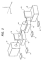
- Fig. 2 is a view which schematically shows the structure of a laser processing apparatus to which the method for manufacturing liquid jet recording heads in accordance with the present invention.
- Fig. 3 is a view which schematically shows the processing mode of the discharge port plate of a ceiling plate to be processed in accordance with a first embodiment of the present invention.
- Fig. 4 is a view which schematically shows the processing mode of the discharge port plate of the ceiling plate to be processed in accordance with the first embodiment of the present invention.
- Fig. 5 is a view which schematically shows the processing mode of the discharge port plate of the ceiling plate to be processed in accordance with the first embodiment of the present invention.
- Fig. 6 is a view which schematically shows the processing mode of the discharge port plate of the ceiling plate to be processed in accordance with the first embodiment of the present invention.
- Fig. 7 is a perspective view which schematically shows the fundamental mode of a liquid jet recording head with the resin ceiling plate which is partially broken for representation.
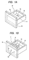
- Figs. 1A and 1B are perspective views which illustrate the ceiling plate of a liquid jet recording head to which the method for manufacturing liquid jet recording heads in accordance with the present invention is applied;
- Fig. 1A is a perspective view which shows the ceiling plate blank integrally formed by means of an injection molding or the like;
- Fig. 1B is a perspective view which shows the ceiling plate having the flow path grooves and the discharge ports formed by processing.
- the ceiling plate blank 2o is provided with the main body portion 2a having the common liquid chamber 2c and the cylindrical protrusion (not shown) having the liquid supply opening 2e which is communicated with the common liquid chamber 2c, and also, with the discharge port plate 2b.
- This is a roughly molded resin product with these parts are integrally formed by known injection molding or the like.
- a plurality of flow path grooves 2f are processed by the irradiation of laser beam onto the flow path processing surface A of the ceiling blank 2o. The flow path grooves 2f thus processed are formed to be communicated with the common liquid chamber 2c as shown in Fig. 1B.
- the laser processing apparatus used for the aforesaid grooving and drilling comprises a laser oscillator 10 that serves as the light source to emit the laser beam L; a controller 11 that changes the oscillation voltages and oscillation frequencies of the laser beam L from the oscillator 10 for application; a mask 12 provided with the opening patterns for grooving and/or drilling; a movement driving device 13 that moves the mask 12 forward or backward (axis X) in the optical axis direction of the laser beam L, and then, in the directions of axes Y and Z, and a controller 14 that controls such movement; a projection optical system 15 that projects the opening patterns of the mask 12 onto the processing part of the ceiling plate 2 which is the work W to be processed; a rotation driving device 16 that rotates the projection optical system 15 around the optical axis of the laser beam L; and a controller 17 that controls such rotation.
- a laser oscillator 10 that serves as the light source to emit the laser beam L
- a controller 11 that changes the oscillation voltages and oscillation frequencies
- the ceiling plate 2 which is the work W to be processed is positioned within a plane (Y-Z plane) perpendicular to the optical axis (axis X) of the laser beam L by means of the movement stage 18 which is controlled by use of a controller 19.
- the movement driving device 13 of the mask 12 is provided with a driving mechanism using a stepping motor, a servo motor, or the like. Then, with the controller 14, it is possible to adjust the movement of the mask 12 in the arrangement direction (axis Y) of the opening patterns for use of grooving and/or drilling or in the rotational direction centering on the optical axis of the laser beam L in a precision of micron unit. Also, as to the movement of the mask 12, it is possible to select the continuous movement at a specific speed or the intermittent movements at specific intervals.
- the irradiation of laser beam in a higher energy concentration per hour in order to obtain grooves and holes in desired dimensions at desired pitches, and also, in order to make the discharge ports larger in a shorter period of processing time as possible. For example, if a processing is made with the laser beam energy concentration of 1J/cm 2 per unit hour at the laser oscillation frequency of 200 Hz, it is possible to complete the processing of discharge ports having a large area by the irradiation of laser beam for several seconds.
- the laser beam is irradiated onto the resin blank of the ceiling plate.
- the discharge ports are processed, the byproducts are created eventually.
- Fig. 3 is an enlarged view which schematically shows the mode in which a discharge port is processed by the irradiation of laser beam onto the discharge port plate of the ceiling blank.
- a reference mark L designates the laser beam that passes the opening pattern of the mask, and 21, the discharge port plate of the ceiling plate with the water-repellent layer 22 being formed on the liquid discharge surface side before the execution of laser processing.
- the water-repellent agent Cytop (Product name: manufactured by Asahi Glass K.K.) is used. After the Cytop is applied to the discharge port plate 21, the water-repellent layer 22 is formed with heat treatment at 120°C for one hour.
- a reference numeral 23 designates a discharge port formed by the laser processing, and 24, the byproducts adhering to the circumference of the discharge port 23 formed by the laser processing.
- the laser beam L is incident upon the surface of the discharge port plate 21 where no water-repellent layer 22 is formed after having passed the mask.
- the discharge port 23 is processed and formed by ablation made by the irradiation of laser beam.
- a chemical surface modification process is given to the byproducts 24 created following the laser processing, which adhere to the surface where the water-repellent layer 22 is formed on the discharge port plate 21.
- it is intended to suppress the increase of the surface energy of the ceiling plate blank due to the adhesion of the byproducts, thus characteristically preventing the blank surface from becoming hydrophilic.
- the chemical surface modification is given to the byproducts.
- the throughput of the product manufacture is enhanced accordingly, thus making it possible to implement the reduction of manufacture costs.
- the gaseous molecules 26 that contain fluorine atom in its structure are blown to the processing parts, thus forming the resin atmosphere that contains fluorine.
- the nozzle 25 is arranged in the vicinity of the processing part in order to blow the gaseous molecules 26 having the fluorine atom in its structure.
- the discharge ports are processed by the irradiation of laser beam L
- the gaseous molecules 26 that contain fluorine atom in its structure are blown out from the nozzle 25 to the processing parts. In this manner, part of the laser beam L irradiates the gaseous molecules 26 when used for processing.
- the fluorine atom having a higher reaction is created from the gaseous molecules 26.
- the chemical surface modification is made on the byproducts that have been created by the irradiation of laser beam L. It is then attempted to fluorinate the surface of the byproducts. In this way, the chemical modification is performed on the surface of the byproducts that causes the surface energy to rise when adhering to the blank.
- the surface of the byproducts are thus fluorinated so as to suppress the phenomenon that may bring about the local hydrophilicity on the surface of the discharge port plate due to the adhesion of the byproducts.
- this method enables the water-repellency of the related surface to be enhanced more than the conventional art.
- tetrafluoromethane (its molecular formula: CF 4 ), for example.
- CF 4 the molecular formula
- Tetrafluoromethane is a stable gas in the air at the room temperature in its gaseous form. Its handling is easy so that it is easily introduced for use in the manufacture processes of liquid jet recording heads.
- the gas chamber is closely installed on the discharge port surface to blow gas so as to obtain the effect of the fluorination sufficiently at the room temperature under the atmospheric pressure.
- the liquid jet recording head is manufactured, and mounted on a printer to record on a recording sheet with the observation given to the discharged liquid droplets. It is then confirmed that the discharge direction of flying droplets are stabilized with the result that prints are in a better condition as compared with the liquid jet recording head having the byproducts created at the time of discharge port formation but not given any chemical surface modification.
- Fig. 5 is a view which schematically shows the processing mode of the discharge port plate of the ceiling plate processed in accordance with a second embodiment of the present invention.
- the resin having the fluorine atom in its structure is positioned extremely close to the processing part of the blank when it is processed by use of the laser processing apparatus shown in Fig. 2. Then, the laser beam L used for processing is irradiated onto the resin in order to apply the chemical surface modification treatment to the byproducts.
- a reference numeral 27 designates the resin that contains the fluorine atom in its structure, which is positioned extremely close to the processing part of the blank.
- the water-repellent layer 22 is formed on the discharge port plate 21. The laser beam is incident upon from the surface where no water-repellent layer 22 is formed.
- the discharge ports are processed by the irradiation of laser beam L
- part of the laser beam L for use of processing is irradiated onto the resin 27 positioned extremely close to the processing part, which contains the fluorine atom in its structure, so as to create highly reactive fluorine atom from the resin 27.
- the chemical surface modification is given to the byproducts created by the irradiation of laser beam L, thus implementing to fluorinate the surface of the byproducts.
- the chemical surface modification is performed on the byproducts that adheres to the blank surface to raise the surface energy.
- the surface of the byproducts is fluorinated.
- the surface of the discharge port plate is provided with the stabilized water-repellency, hence suppressing the occurrence of the phenomenon in which the hydrophilicity is locally created by the adhesion of the byproducts.
- the irradiation of the laser beam L onto the resin 27 that contains fluorine atom in its structure it becomes possible to partly polymerize the surface of the byproducts again by the resin using the energy of the laser beam L. In this way, the surface of the byproducts is further modified chemically to implement fluorinating the surface thereof.
- the resin that contains fluorine atom in its structure it is possible to use polytetrafluoroethylene, for example.
- polytetrafluoroethylene when the discharge ports are processed by the irradiation of laser beam, polytetrafluoroethylene is positioned extremely close to the processing part of the blank. Then, part of the laser beam L is irradiated onto polytetrafluoroethylene to enable it to create the highly reactive fluorine atom. With this highly reactive fluorine atom, the modification is chemically made on the surface of the byproducts 24, hence attempting to fluorinate the surface thereof. Also, it is possible to implement fluorinating the surface of the byproducts by polymerizing polytetrafluoroethylene again on its surface. Now that polytetrafluoroethylene can be processed into solid in a sheet form at the room temperature under the atmospheric pressure, its handling and procurement are easy so that it is easily introduced for use in the manufacture processes of liquid jet recording heads.
- the resin that contains fluorine atom in its structure in a position on the discharge port surface with a gap of 1 mm or less in order to obtain the sufficient effect of fluorination at the room temperature under the atmospheric pressure.
- the liquid jet recording head is manufactured, and mounted on a printer to record on a recording sheet with the observation given to the discharged liquid droplets. It is then confirmed that the discharge direction of flying droplets are stabilized with the result that prints are made in a better condition as compared with the liquid jet recording head having the byproducts created at the time of discharge port formation but not given any chemical surface modification.
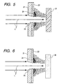
- Fig. 6 is a view which schematically shows the mode of processing the discharge port plate of the ceiling plate in accordance with a third embodiment of the present invention.
- an absorbent such as a sponge, that contains a solution having the polymer containing fluorine atom in its structure as solvent in the solution, is positioned extremely close to the processing part of the blank.
- the laser beam for use of processing is irradiated onto the absorbent to give the chemical surface modification to the byproducts of the laser processing.
- a reference numeral 28 designates the absorbent that contains the solution having the polymer containing the fluorine atom in its structure as solvent in the solution, which is positioned extremely close to the processing part of the blank.
- the water-repellent layer 22 is formed on the discharge port plate 21. The laser beam is incident upon from the surface where no water-repellent layer 22 is formed.
- part of the laser beam L for use of processing is irradiated onto the absorbent 28 that contains polymer having fluorine atom in its structure as solvent in the solution, which is positioned extremely close to the processing part, so as to create highly reactive fluorine atom from the solution having fluorine atom in its structure, which is contained in the absorbent 28.
- the chemical surface modification is given to the byproducts created by the irradiation of laser beam L, thus implementing to fluorinate the surface of the byproducts. In this manner, the chemical surface modification is performed on the byproducts that adheres to the blank surface to raise the surface energy.
- the surface of the byproducts is fluorinated. Then, the surface of the discharge port plate is given the stabilized water-repellency, hence suppressing the occurrence of the phenomenon in which the hydrophilicity is locally created by the adhesion of the byproducts.
- the liquid jet recording head is manufactured, and mounted on a printer to record on a recording sheet with the observation given to the discharged liquid droplets. It is then confirmed that the discharge direction of flying droplets is stabilized with the result that prints are in a better condition as compared with the liquid jet recording head having the byproducts created at the time of discharge port formation but not given any chemical surface modification.
- the present invention it may be possible to combine the blowing of the gaseous molecules with the resin that contains fluorine atom in its structure or with the absorbent that contains the solution having polymer containing fluorine atom as solvent in the solution.
- the chemical surface modification is given to the byproducts that raise the surface energy when adhering to the blank.
- the surface of the byproducts is fluorinated.
- the surface of the discharge port plate shows the stabilized water-repellency, making it possible to suppress the occurrence of the phenomenon in which the hydrophilicity is locally created by the adhesion of the byproducts.
- the liquid jet recording head is manufactured, and mounted on a printer to record on a recording sheet with the observation given to the discharged liquid droplets. It is then confirmed that the discharge direction of flying droplets are stabilized with the result that prints are in a better condition as compared with the liquid jet recording head having the byproducts created at the time of discharge port formation but not given any chemical surface modification.
- the structure is the same as the first embodiment where the gaseous molecules, which contain fluorine atom in its structure, are blown to give the fluorine resin atmosphere to the discharge port plate on the side where the water-repellent layer is formed.
- the ablation processing is made in such a manner that an intermediate reactive substance that may easily react upon the laser beam is positioned extremely close to the processing part on the surface where the water-repellent layer is formed.
- the absorptance of the gaseous molecules that contain fluorine atom in its structure is often smaller with respect to the laser beam.
- the excitation life of the fluorine contained substance CxFy which is activated by the laser beam, is very long.
- the laser beam is irradiated, while gas is blown in a state where the intermediately reactive substance M is arranged. Then, part of the laser beam thus irradiated enables the fluorine contained substance CxFy to be activated directly to create the active seeds CF, CF2, and CF3. These seeds react upon the surface of the discharge port plate to make the surface water-repellent.
- the laser beam is irradiated onto the intermediately reactive substance M.
- the substance M* thus activated collides with the fluorine contained substance CxFy to develop the active seeds CF, CF2, and CF3.
- the intermediately reactive substance M is the substance that can absorb the laser beam easily, and its active life is longer. As a result, there is an extremely high probability that this substance can collide with the fluorine contained substance CxFy.
- the active seeds CF, CF2, and CF3 thus formed react upon the surface of the discharge port plate as in the previous case.
- the active substance M* that has collided with the fluorine contained substance CxFy loses its energy, and returns to the basic state of M.
- the excimer laser is used for processing as a coherent laser source in order to process the discharge ports by means of ablation at a time by use of the laser processing apparatus shown in Fig. 2.
- the excimer laser is the laser capable of oscillating ultraviolet beam. It has a good monochromaticity with a higher intensity, as well as a good directivity. Therefore, it can be oscillated in short pulses, and has an advantage, among many others, that when it is converged by use of lens, the energy concentration is made extremely great.
- the excimer laser oscillator is an apparatus that can oscillate ultraviolet beam in short pulses (15 to 35 ns) by discharging the mixed gas of rare gas and halogen for its excitation, and often uses Kr-F laser, Xe-C1 laser, or Ar-F laser.
- the oscillated energy of such laser is several hundreds of mj/pulse, and the pulse repetition frequency is 30 to 1,000 Hz.
- KrF laser which is excimer laser beam
- KrF laser is used to process the discharge ports at a time by means of ablation.
- liquid jet recording heads capable of printing in high quality with the stabilized discharge directivity of flying droplets by the utilization of excellent characteristics of excimer laser when used for a processing of the kind.
- the present invention demonstrates an excellent effect with respect to the recording head and recording apparatus of the so-called ink jet recording type, which performs recording by forming flying droplets particularly by the utilization of thermal energy among those liquid jet recording methods.
- discharge signals are supplied from a driving circuit to electrothermal transducing elements, which serve as discharge energy generating elements, disposed on a liquid (ink) retaining sheet or liquid path.
- at least one driving signal is given in order to provide recording liquid (ink) with a rapid temperature rise so that film boiling phenomenon, which is beyond nuclear boiling phenomenon, is created in the liquid, thus generating thermal energy to cause film boiling on the thermoactive surface of the recording head. Since a bubble can be formed from the recording liquid (ink) by means of the driving signal given to an electrothermal converting element one to one, this method is effective particularly for the on-demand type recording method.
- the liquid (ink) is discharged through each discharge port to produce at least one droplet.
- the driving signal is more preferably in the form of pulses because the development and contraction of the bubble can be effectuated instantaneously and appropriately.
- the liquid (ink) is discharged with quicker response.
- the driving signal in the form of pulses is preferably such as disclosed in the specifications of U.S. Patent Nos. 4,463,359 and 4,345,262.
- the temperature increasing rate of the thermoactive surface is preferably such as disclosed in the specification of U.S. Patent No. 4,313,124 for an excellent recording in a better condition.
- the present invention is effectively applicable to those which are shown in each of the above-mentioned specifications wherein the structure is arranged to combine the discharging openings, liquid paths, and the electrothermal converting elements (linear type liquid paths or right-angled liquid paths). Besides, it is equally and effectively applicable to the structure such as disclosed in the specifications of U.S. Patent Nos. 4,558,333 and 4,459,600 in which the thermal activation portions are arranged in a curved area.
- the present invention is effectively applicable to the structure disclosed in Japanese Patent Application Laid-Open No. 59-123670 wherein a common slit is used as the discharging ports for plural electrothermal transducing elements, and to the structure disclosed in Japanese Patent Application Laid-Open No. 59-138461 wherein an aperture for absorbing pressure waves of thermal energy is formed corresponding to the discharge ports.
- the full-line type recording head whose length corresponds to the maximum width of a recording medium recordable by such recording apparatus.
- the full-line type recording head it may be possible to adopt either a structure whereby to satisfy the required length by combining a plurality of recording heads or a structure arranged by one recording head integrally formed.
- the present invention is effectively applicable to an exchangeable recording head of a chip type that can be electrically connected with the apparatus main body, the ink supply therefor being made possible from the apparatus main body, when mounted on the apparatus main body or to the use of a cartridge type recording head provided integrally for the recording head itself.
- a recording head with recovery means and preliminarily auxiliary means because these additional means will contribute to making the effectiveness of a recording apparatus more stabilized.
- these additional means are capping means, cleaning means, suction or compression means, preheating means such as electrothermal converting elements or heating devices other than such transducing devices or the combination of those types of devices, and a predischarge means for performing discharge other than the regular discharge with respect to the recording head.
- the present invention is not only applicable to a recording mode in which only one main color such as black is used for recording, but also, the invention is extremely effective in applying it to an apparatus having plural recording heads provided for use of at least one of multiple colors prepared by different colors or full-color prepared by mixing colors, irrespective of whether the recording heads are integrally structured or structured by a combination of plural recording heads.
- the ink has been described as liquid, it may be an ink material which is solidified below the room temperature but soften or liquefied at the room temperature or soften or liquefied within a temperature range of the temperature adjustment generally practiced for an ink jet recording, that is, not lower than 30°C but not higher than 70°C. In other words, it should be good enough if only ink is liquefied at the time of giving recording signals for use.
- an ink having a nature of being liquefied only by the application of thermal energy such as an ink capable of being discharged as ink liquid by enabling itself to be liquefied anyway when the thermal energy is given in accordance with recording signals, and an ink which will have already begun solidifying itself by the time it reaches a recording medium.
- ink in the form of liquid or solid in the recesses or through holes of a porous sheet such as disclosed in Japanese Patent Application Laid-Open Nos. 54-56847 or 60-71260 in order to enable the ink to face the electrothermal converting elements.
- the most effective method for the various kinds of ink mentioned above is the one that enables the film boiling method to be effectuated as described above.
- the mode of the recording apparatus described above it may be possible to adopt a copying apparatus combined with a reader, in addition to the image output terminal for a computer or other information processing apparatus. Also, for the recording apparatus described above, it may be possible to adopt a mode of a facsimile equipment provided with transmitting and receiving functions.
- liquid jet recording heads there is no need for the provision of any special processes in order to remove the byproducts adhering to the ceiling plate. Therefore, in the manufacture of liquid jet recording heads, it also becomes possible to solve the problem encountered in the conventional art that the product throughput is considerably lowered. With the solution of such problem, liquid jet recording heads can be manufactured at lower costs with a good product throughput.
Description
- The present invention relates to a method for manufacturing liquid jet heads whereby to manufacture a resin ceiling plate by means of grooving, drilling, or the like by the irradiation of laser beam. The invention also relates to an apparatus therefor.
- The liquid jet recording head, which is used for the liquid jet recording apparatus or the like that records or prints on a recording sheet by discharging ink or other recording liquid from the fine discharge ports (orifices) as flying droplets, is provided with an elemental substrate (heater board) having on it a plurality of discharge energy generating devices (electrothermal converting elements, for example) and lead electrodes therefor as well. On this elemental substrate, a resin nozzle layer (liquid flow path formation layer) is laminated to form the liquid flow paths (nozzles) and a common liquid chamber. Then, it is generally practiced to overlay on it the glass ceiling plate provided with supply tubes of recording liquid. In recent years, however, it has been developed to manufacture a liquid jet recording head in such a manner that while the glass ceiling plate is omitted, the resin ceiling plate is integrally produced with liquid flow path grooves and the common liquid chamber, together with the supply tube of recording liquid, by means of the injection molding or the like, and then, discharge ports are processed for its formation, and then, the ceiling plate is pressed to the elemental substrate by use of elastic member for the integral formation of a head. A liquid jet head of the kind makes it possible to reduce part numbers significantly, and also, makes the assembling processes simpler. Therefore, it is anticipated that the liquid jet recording heads thus developed will contribute to the considerable reduction of costs when liquid jet recording apparatuses are manufactured using such heads.
- Fig. 7 shows the principal part of the liquid jet recording head that uses the resin ceiling plate formed as described above. In Fig. 7, the liquid jet recording head Eo is shown with the resin ceiling plate which is partly broken in its representation. This head is provided with an
elemental substrate 101 having a plurality of electrothermal convertingelements 101a serving as discharge energy generating devices, and theresin ceiling plate 102 havingflow path grooves 102f each positioned on each of theelectrothermal converting elements 101a, and also, the commonliquid chamber 102 communicated with each of them. For theresin ceiling plate 102, there are arranged integrally, thedischarge port plate 102b provided with discharge ports (orifices) each communicated with each of theflow path grooves 102f, and thecylindrical protrusion 102d provided with theliquid supply opening 102 that opens to the commonliquid chamber 102c. - At first, the resin ceiling plate is formed integrally by means of the injection molding or the like, with the
discharge port plate 102b andcylindrical protrusion 102d, in addition to theflow path grooves 102f and the common liquid chamber, altogether. Then, after thedischarge ports 102g are processed, theresin ceiling plate 102 is positioned so as to bring each of theflow path grooves 102f to be placed exactly on each of theelectrothermal converting elements 101a on theelemental substrate 101. Thus, by means of the elastic member (not shown), theceiling plate 102 is pressed to theelemental substrate 101 to be bonded together. In this respect, theelemental substrate 101 is fixed on abase plate 104 by means of screws or some other known means, together with the printed-circuit board 103 having driving circuit provided therefor to generate electric signals to each of theelectrothermal converting elements 101a. - Also, a method has been developed to manufacture the
resin ceiling plate 102 in such a manner that at first, a blank (roughly molded product) is produced by means of the injection molding or the like integrally with themain body portion 102a before the flow path grooves are provided, and thedischarge port plate 102b before thedischarge ports 102g are formed, and then, by use of the excimer laser beam, each of theflow path grooves 102f is processed on themain body portion 102a, and likewise, each of thedischarge ports 102g is drilled on thedischarge port plate 102b. - In this way, with the molding formation combined with the laser processing, it becomes possible to simplify the preparation of the molding die for processing, as well as the processing itself, because it is not required for the die used for processing the ceiling plate formation to prepare any particular member additionally for the formation of flow path portion. Further, since the laser processing performs its processing in a higher precision at a shorter period of time, the resin ceiling plates are produced at lower costs, thus promoting the reduction of costs still more for the manufacture of liquid jet heads.
- Then, as the laser processing apparatus used for grooving and drilling by irradiating the laser beam onto the resin blank which is produced by the injection molding, it is suitable to adopt the one that emits excimer laser. A laser processing apparatus of the kind is generally provided with an excimer laser oscillator serving serves as the laser light source that emits the excimer laser beam; masks having the patterns of the flow path grooves and openings; and the optical system that projects the opening patterns onto the blank of the ceiling plate by the use of the excimer laser beam.
- Now, however, when drilling is made by a technique of the kind for the formation of discharge ports, the byproducts that are created at the time of laser processing and allowed to adhere to the processing surface of the ceiling plate. Then, the surface energy per hour becomes higher on the portions where the byproducts have adhered, and the resultant wettability becomes higher with respect to the recording liquid. In other words, such surface becomes hydrophilic.
- In order to enhance the discharge efficiency of the recording liquid at its discharge ports of a liquid jet head, it is desirable to make them water- repellent in order to avoid any stronger interaction between liquid and resin. Particularly, if the circumference of the discharge ports (orifices) of the discharge port plate should become hydrophilic, the smooth discharge of recording liquid is hindered. As a result, image deviation may take place when recording or printing is made on a recording medium, such as recording paper sheet, or the discharge of recording liquid may be disabled, thus presenting critical problems related to the product performance. Therefore, the water-repellent resin is coated on the resin surface. Then, the coated resin is hardened by the application of beam or heat treatment to form the water-repellent layer on the resin surface. Also, depending on the resin material, such water-repellent layer is formed by evaporating the solvent that resolves such resin material or the dispersion medium that disperses it by giving heat treatment.
- Therefore, it is important to prevent the resin surface energy from rising due to the byproducts created at the time of laser processing. In order to avoid the rise of resin surface energy due to the adhesion of the byproducts, that is, to prevent the surface from becoming hydrophilic, there is known a technique, such as disclosed in the specification of Japanese Patent Application Laid-Open No. 4-279356, whereby to perform heat treatment, ultrasonic rinsing, ultrasonic water flow rinsing, high pressure water flow rinsing, or the like or to repeat applying adhesive tape and peeling it off so that the byproducts adhering to the circumference of the discharge port (orifices) are removed after the grooves or holes are formed on the resin blank by the irradiation of excimer laser.
- Further, as disclosed in the specification of Japanese Patent Application Laid-Open No. 4-279355, there is known a method whereby to remove byproducts in such a manner that at first, resist or the like is coated on the resin surface provisionally, and than, the byproducts are rinsed by use of developer, together with the resist, to remove them all after the grooves and holes are formed on the resin blank by the irradiation of excimer laser.
- However, in accordance with the aforesaid technique, the method of removing the byproducts should give heat treatment at a high temperature for a long time such as at 120°C for an hour after having drilled holes, which serve the liquid discharge ports, by the irradiation of laser beam on the resin blank, or such method should dry the processed resin blank after rinsing it by the application of ultrasonic waves or by use of the ultrasonic water flow. Also, there is a need for a process dedicated to the removable of the byproducts if the adhesion of the byproducts on the surface of the resin blank should be removed by use of the adhesive tapes for peeling off. Also, for the method in which resist is coated in advance, and the byproducts are removed together with the resist by use of the developer, it is necessary to provide a special process to develop the resist and rinse it off after the laser processing.
- As described above, therefore, the conventional techniques to remove the byproducts need one special process or another for the execution of the designated treatments, which leads to increasing the costs of manufacture, and also, taking more time in completing the required processes. These affect the production efficiency seriously, thus presenting the problems yet to be solved with respect to the extremely lowered throughput of production.
- Therefore, the present invention is designed in consideration of these problems yet to be solved in the conventional art as described above. It is an object of the invention to provide a method for manufacturing liquid jet recording heads capable of solving without any provision of special processing steps the problem encountered in the conventional art that when the holes are processed to make liquid discharge ports on the resin blank by the irradiation of laser beam, the surface energy of resin is increased due to the adhesion of byproducts to the surface of the blank, thus being made capable of enhancing the throughput of product manufacture.
- In order to achieve the aforesaid objectives, the method of the present invention for manufacturing liquid jet recording heads, each provided with discharge ports to discharge liquid and a discharge port plate having the discharge ports by collectively performing ablation processing of holes becoming the discharge ports by use of a mask for projecting the image of the mask onto the discharge port plate with coherent laser beam as light source, comprises the following steps of forming water-repellent layer on the surface of the discharge port plate on the liquid discharge side; and of performing the ablation processing by irradiating the laser beam from the reverse side of the surface of discharge port plate having the water-repellent layer formed thereon in a state of the surface of discharge port plate having the water-repellent layer formed thereon being arranged to be under an atmosphere containing fluorine atoms, and forming the discharge ports and enabling the atmosphere containing the fluorine atoms excited by the laser beam to adhere to the surface having the water-repellent layer formed thereon.
- For the method of the present invention for manufacturing liquid jet heads, it is preferable to use tetrafluoromethane as gas to be blown onto the object to be processed.
- Also, for the method of the present invention for manufacturing liquid jet heads, it is preferable to use polytetrafluoroethylene as resin to be located extremely close to the object to be processed.
- For the method of the present invention for manufacturing liquid jet heads, it is preferable to use ultraviolet laser, particularly excimer laser as the laser beam therefor.
- With the coherent laser beam as the light source, this method uses the mask to project the image thereof onto the roughly molded product, and the holes that become the discharge ports are processed at a time by means of ablation. When ablation is performed by the irradiation of laser beam, it is arranged to carry out the chemical surface modification in a state of atmosphere containing fluorine atom on the byproducts to be created by the irradiation thereof. In this way, it is made possible to suppress the increase of surface energy of the blank caused by the adhesion of the byproducts, hence preventing the surface of the blank from becoming hydrophilic. In other words, it is possible to give treatment of chemical surface modification on the byproducts, while performing the laser beam processing simultaneously. As a result, there is no need for any provision of extra process in order to remove the byproducts. In this manner, the throughput of product manufacture is enhanced to reduce the costs of manufacture accordingly. Further, it becomes possible to implement enhancing the water-repellency to improve the printing quality.
- With the gaseous molecules containing fluorine atom in its structure, tetrafluoromethane, for example, being blown to the laser processing part or with the resin that contains fluorine atom in its structure, polytetrafluoroethylene, for example, or the absorbent having the solution with the solvent that contains polymer having fluorine atom in its structure, being placed extremely close to the processing part, highly reactive fluorine atom is created by the irradiation of laser beam. Then, with the fluorine atom thus created, the byproducts caused by the irradiation of laser beam is provided with the chemical surface modification, thus implementing to fluorinate the surface thereof. With such chemical surface modification as to fluorinate the byproducts adhering to the surface of the blank which raises the surface energy thereof, the surface of the discharge port plate is stabilized and allowed to present water-repellency. In this manner, it becomes possible to suppress the occurrence of the phenomenon that the hydrophilicity is created locally due to the adhesion of the byproducts.
- Also, using ultraviolet laser, particularly excimer laser beam the discharge ports are processed at a time. With the excellent characteristics of excimer laser when used for a processing of the kind, it becomes possible to manufacture liquid jet recording heads having the stabilized directivity of flying droplets for the performance of high quality printing. Further, it becomes possible to create highly reactive fluorine atom from the substance containing fluorine atom by the application of high energy of the excimer laser beam.
- Figs. 1A and 1B are perspective views which illustrate the ceiling plate of a liquid jet recording head to which the method for manufacturing liquid jet recording heads in accordance with the present invention; Fig. 1A is a perspective view which shows the ceiling plate blank integrally formed by means of an injection molding or the like; Fig. 1B is a perspective view which shows the ceiling plate having the flow path grooves and the discharge ports formed by processing.
- Figs. 1A and 1B are perspective views which illustrate the ceiling plate of a liquid jet recording head to which the method for manufacturing liquid jet recording heads in accordance with the present invention; Fig. 1A is a perspective view which shows the ceiling plate blank integrally formed by means of an injection molding or the like; Fig. 1B is a perspective view which shows the ceiling plate having the flow path grooves and the discharge ports formed by processing.
- Fig. 2 is a view which schematically shows the structure of a laser processing apparatus to which the method for manufacturing liquid jet recording heads in accordance with the present invention.
- Fig. 3 is a view which schematically shows the processing mode of the discharge port plate of a ceiling plate to be processed in accordance with a first embodiment of the present invention.
- Fig. 4 is a view which schematically shows the processing mode of the discharge port plate of the ceiling plate to be processed in accordance with the first embodiment of the present invention.
- Fig. 5 is a view which schematically shows the processing mode of the discharge port plate of the ceiling plate to be processed in accordance with the first embodiment of the present invention.
- Fig. 6 is a view which schematically shows the processing mode of the discharge port plate of the ceiling plate to be processed in accordance with the first embodiment of the present invention.
- Fig. 7 is a perspective view which schematically shows the fundamental mode of a liquid jet recording head with the resin ceiling plate which is partially broken for representation.
- Hereinafter, with reference to the accompanying drawings, the description will be made of the embodiment in accordance with the present invention.
- Figs. 1A and 1B are perspective views which illustrate the ceiling plate of a liquid jet recording head to which the method for manufacturing liquid jet recording heads in accordance with the present invention is applied; Fig. 1A is a perspective view which shows the ceiling plate blank integrally formed by means of an injection molding or the like; Fig. 1B is a perspective view which shows the ceiling plate having the flow path grooves and the discharge ports formed by processing.
- As shown in Fig. 1A, the ceiling plate blank 2o is provided with the
main body portion 2a having thecommon liquid chamber 2c and the cylindrical protrusion (not shown) having theliquid supply opening 2e which is communicated with thecommon liquid chamber 2c, and also, with thedischarge port plate 2b. This is a roughly molded resin product with these parts are integrally formed by known injection molding or the like. A plurality offlow path grooves 2f are processed by the irradiation of laser beam onto the flow path processing surface A of the ceiling blank 2o. Theflow path grooves 2f thus processed are formed to be communicated with thecommon liquid chamber 2c as shown in Fig. 1B. After that, drilling is performed by the irradiation of laser beam to process and form a plurality ofdischarge ports 2g in the positions on thedischarge port plate 2b corresponding to each of theflow path grooves 2f as shown in Fig. 1B. Then, theresin ceiling plate 2 thus processed is bonded to the elemental substrate provided with a plurality of electrothermal converting elements on its surface subsequent to having positioned the ceiling plate to the elemental substrate. - Now, as shown in Fig. 2, the laser processing apparatus used for the aforesaid grooving and drilling comprises a
laser oscillator 10 that serves as the light source to emit the laser beam L; acontroller 11 that changes the oscillation voltages and oscillation frequencies of the laser beam L from theoscillator 10 for application; amask 12 provided with the opening patterns for grooving and/or drilling; amovement driving device 13 that moves themask 12 forward or backward (axis X) in the optical axis direction of the laser beam L, and then, in the directions of axes Y and Z, and acontroller 14 that controls such movement; a projectionoptical system 15 that projects the opening patterns of themask 12 onto the processing part of theceiling plate 2 which is the work W to be processed; arotation driving device 16 that rotates the projectionoptical system 15 around the optical axis of the laser beam L; and acontroller 17 that controls such rotation. Theceiling plate 2 which is the work W to be processed is positioned within a plane (Y-Z plane) perpendicular to the optical axis (axis X) of the laser beam L by means of themovement stage 18 which is controlled by use of acontroller 19. Themovement driving device 13 of themask 12 is provided with a driving mechanism using a stepping motor, a servo motor, or the like. Then, with thecontroller 14, it is possible to adjust the movement of themask 12 in the arrangement direction (axis Y) of the opening patterns for use of grooving and/or drilling or in the rotational direction centering on the optical axis of the laser beam L in a precision of micron unit. Also, as to the movement of themask 12, it is possible to select the continuous movement at a specific speed or the intermittent movements at specific intervals. - Also, by use of a computer or the like, it is possible to carry out the comprehensive control of the
controllers laser oscillator 10 and each of the movement driving altogether. - The laser beam that has passed the
mask 12, which is arranged for the formation of the liquid flow path grooves and of the discharge ports, performs its ablation on the ceiling plate, which is the work W, instantaneously. At this juncture, there is a need for the irradiation of laser beam in a higher energy concentration per hour in order to obtain grooves and holes in desired dimensions at desired pitches, and also, in order to make the discharge ports larger in a shorter period of processing time as possible. For example, if a processing is made with the laser beam energy concentration of 1J/cm2 per unit hour at the laser oscillation frequency of 200 Hz, it is possible to complete the processing of discharge ports having a large area by the irradiation of laser beam for several seconds. - With a laser processing apparatus of the kind, the laser beam is irradiated onto the resin blank of the ceiling plate. However, when the discharge ports are processed, the byproducts are created eventually.
- Fig. 3 is an enlarged view which schematically shows the mode in which a discharge port is processed by the irradiation of laser beam onto the discharge port plate of the ceiling blank. Here, a reference mark L designates the laser beam that passes the opening pattern of the mask, and 21, the discharge port plate of the ceiling plate with the water-
repellent layer 22 being formed on the liquid discharge surface side before the execution of laser processing. As the water-repellent agent, Cytop (Product name: manufactured by Asahi Glass K.K.) is used. After the Cytop is applied to thedischarge port plate 21, the water-repellent layer 22 is formed with heat treatment at 120°C for one hour. Areference numeral 23 designates a discharge port formed by the laser processing, and 24, the byproducts adhering to the circumference of thedischarge port 23 formed by the laser processing. - In accordance with the present invention, the laser beam L is incident upon the surface of the
discharge port plate 21 where no water-repellent layer 22 is formed after having passed the mask. Then, thedischarge port 23 is processed and formed by ablation made by the irradiation of laser beam. After that, a chemical surface modification process is given to thebyproducts 24 created following the laser processing, which adhere to the surface where the water-repellent layer 22 is formed on thedischarge port plate 21. Here, it is intended to suppress the increase of the surface energy of the ceiling plate blank due to the adhesion of the byproducts, thus characteristically preventing the blank surface from becoming hydrophilic. In this process, at the same time that the laser processing is performed, the chemical surface modification is given to the byproducts. Thus, there is no need for the provision of any additional step for the removal of the adhesive byproducts. The throughput of the product manufacture is enhanced accordingly, thus making it possible to implement the reduction of manufacture costs. - Now, in conjunction with Fig. 4, the description will be made of the embodiment of a structure that forms the atmosphere that contains fluorine atom. Here, in Fig. 4, the same reference marks are applied to the same members and elements as those appearing in Fig. 3, and the description thereof will be omitted.
- In accordance with the present embodiment, when the blank is processed by use of the laser processing apparatus shown in Fig. 2, the
gaseous molecules 26 that contain fluorine atom in its structure are blown to the processing parts, thus forming the resin atmosphere that contains fluorine. Here, therefore, thenozzle 25 is arranged in the vicinity of the processing part in order to blow thegaseous molecules 26 having the fluorine atom in its structure. Then, when the discharge ports are processed by the irradiation of laser beam L, thegaseous molecules 26 that contain fluorine atom in its structure are blown out from thenozzle 25 to the processing parts. In this manner, part of the laser beam L irradiates thegaseous molecules 26 when used for processing. Then, by the energy of the laser beam L, the fluorine atom having a higher reaction is created from thegaseous molecules 26. By the highly reactive fluorine atom, the chemical surface modification is made on the byproducts that have been created by the irradiation of laser beam L. It is then attempted to fluorinate the surface of the byproducts. In this way, the chemical modification is performed on the surface of the byproducts that causes the surface energy to rise when adhering to the blank. The surface of the byproducts are thus fluorinated so as to suppress the phenomenon that may bring about the local hydrophilicity on the surface of the discharge port plate due to the adhesion of the byproducts. At the same time, this method enables the water-repellency of the related surface to be enhanced more than the conventional art. - In this respect, as the gaseous molecules that contain fluorine atom in its structure, it is possible to use tetrafluoromethane (its molecular formula: CF4), for example. In other words, when the discharge ports are processed by the irradiation of laser beam, tetrafluoromethane is blown from the
nozzle 25 onto the processing parts. Then, part of the laser beam L is irradiated onto tetrafluoromethane to enable it to create the highly reactive fluorine atom by means of the energy of laser beam L. With this highly reactive fluorine atom, the modification is chemically made on the surface of thebyproducts 24, hence attempting to fluorinate the surface of the byproducts. Tetrafluoromethane is a stable gas in the air at the room temperature in its gaseous form. Its handling is easy so that it is easily introduced for use in the manufacture processes of liquid jet recording heads. - In this respect, it is preferable to continue the irradiation of laser beam even after the holes have been made thoroughly for the formation of discharge ports in order to fluorinate the surface of the byproducts. It is preferably suitable to continue the irradiation thereof for substantially the same period of time as it has taken to form the discharge ports.
- Also, in order to unify the fluorination of each of the discharge ports, it is preferable to blow the gaseous molecules from the opposite side of the direction in which the laser beam is irradiated.
- Here, in accordance with the present embodiment, the gas chamber is closely installed on the discharge port surface to blow gas so as to obtain the effect of the fluorination sufficiently at the room temperature under the atmospheric pressure.
- With the ceiling plate thus processed and formed, the liquid jet recording head is manufactured, and mounted on a printer to record on a recording sheet with the observation given to the discharged liquid droplets. It is then confirmed that the discharge direction of flying droplets are stabilized with the result that prints are in a better condition as compared with the liquid jet recording head having the byproducts created at the time of discharge port formation but not given any chemical surface modification.
- Fig. 5 is a view which schematically shows the processing mode of the discharge port plate of the ceiling plate processed in accordance with a second embodiment of the present invention. For the present embodiment, the resin having the fluorine atom in its structure is positioned extremely close to the processing part of the blank when it is processed by use of the laser processing apparatus shown in Fig. 2. Then, the laser beam L used for processing is irradiated onto the resin in order to apply the chemical surface modification treatment to the byproducts.
- In Fig. 5, the same reference marks are applied to the same members and elements appearing in the previous embodiment. The description thereof will be omitted. Now, a
reference numeral 27 designates the resin that contains the fluorine atom in its structure, which is positioned extremely close to the processing part of the blank. In the same manner as the previous embodiment, the water-repellent layer 22 is formed on thedischarge port plate 21. The laser beam is incident upon from the surface where no water-repellent layer 22 is formed. Now, when the discharge ports are processed by the irradiation of laser beam L, part of the laser beam L for use of processing is irradiated onto theresin 27 positioned extremely close to the processing part, which contains the fluorine atom in its structure, so as to create highly reactive fluorine atom from theresin 27. With the highly reactive fluorine atom, the chemical surface modification is given to the byproducts created by the irradiation of laser beam L, thus implementing to fluorinate the surface of the byproducts. In this manner, the chemical surface modification is performed on the byproducts that adheres to the blank surface to raise the surface energy. In other words, the surface of the byproducts is fluorinated. Then, the surface of the discharge port plate is provided with the stabilized water-repellency, hence suppressing the occurrence of the phenomenon in which the hydrophilicity is locally created by the adhesion of the byproducts. - Further, by the irradiation of the laser beam L onto the
resin 27 that contains fluorine atom in its structure, it becomes possible to partly polymerize the surface of the byproducts again by the resin using the energy of the laser beam L. In this way, the surface of the byproducts is further modified chemically to implement fluorinating the surface thereof. - In this respect, as the resin that contains fluorine atom in its structure, it is possible to use polytetrafluoroethylene, for example. In other words, when the discharge ports are processed by the irradiation of laser beam, polytetrafluoroethylene is positioned extremely close to the processing part of the blank. Then, part of the laser beam L is irradiated onto polytetrafluoroethylene to enable it to create the highly reactive fluorine atom. With this highly reactive fluorine atom, the modification is chemically made on the surface of the
byproducts 24, hence attempting to fluorinate the surface thereof. Also, it is possible to implement fluorinating the surface of the byproducts by polymerizing polytetrafluoroethylene again on its surface. Now that polytetrafluoroethylene can be processed into solid in a sheet form at the room temperature under the atmospheric pressure, its handling and procurement are easy so that it is easily introduced for use in the manufacture processes of liquid jet recording heads. - Here, for the present embodiment, it is preferable to locate the resin that contains fluorine atom in its structure in a position on the discharge port surface with a gap of 1 mm or less in order to obtain the sufficient effect of fluorination at the room temperature under the atmospheric pressure.
- With the ceiling plate thus processed and formed, the liquid jet recording head is manufactured, and mounted on a printer to record on a recording sheet with the observation given to the discharged liquid droplets. It is then confirmed that the discharge direction of flying droplets are stabilized with the result that prints are made in a better condition as compared with the liquid jet recording head having the byproducts created at the time of discharge port formation but not given any chemical surface modification.
- Fig. 6 is a view which schematically shows the mode of processing the discharge port plate of the ceiling plate in accordance with a third embodiment of the present invention. For the present embodiment, when the blank is processed by use of the laser processing apparatus shown in Fig. 2, an absorbent, such as a sponge, that contains a solution having the polymer containing fluorine atom in its structure as solvent in the solution, is positioned extremely close to the processing part of the blank. The laser beam for use of processing is irradiated onto the absorbent to give the chemical surface modification to the byproducts of the laser processing.
- In Fig. 6, the same reference marks are applied to the same members and elements appearing in the previous embodiment. The description thereof will be omitted. Now, a
reference numeral 28 designates the absorbent that contains the solution having the polymer containing the fluorine atom in its structure as solvent in the solution, which is positioned extremely close to the processing part of the blank. In the same manner as the previous embodiment, the water-repellent layer 22 is formed on thedischarge port plate 21. The laser beam is incident upon from the surface where no water-repellent layer 22 is formed. Now, when the discharge ports are processed by the irradiation of laser beam L, part of the laser beam L for use of processing is irradiated onto the absorbent 28 that contains polymer having fluorine atom in its structure as solvent in the solution, which is positioned extremely close to the processing part, so as to create highly reactive fluorine atom from the solution having fluorine atom in its structure, which is contained in the absorbent 28. With the highly reactive fluorine atom, the chemical surface modification is given to the byproducts created by the irradiation of laser beam L, thus implementing to fluorinate the surface of the byproducts. In this manner, the chemical surface modification is performed on the byproducts that adheres to the blank surface to raise the surface energy. In other words, the surface of the byproducts is fluorinated. Then, the surface of the discharge port plate is given the stabilized water-repellency, hence suppressing the occurrence of the phenomenon in which the hydrophilicity is locally created by the adhesion of the byproducts. - Further, it is possible to polymerize again the polymer with fluorine atom in its structure in the solution contained in the absorbent 28 on the surface of the byproducts. In this manner, the surface of the byproducts is further modified chemically, thus implementing fluorinating the surface thereof.
- With the ceiling plate thus processed and formed, the liquid jet recording head is manufactured, and mounted on a printer to record on a recording sheet with the observation given to the discharged liquid droplets. It is then confirmed that the discharge direction of flying droplets is stabilized with the result that prints are in a better condition as compared with the liquid jet recording head having the byproducts created at the time of discharge port formation but not given any chemical surface modification.
- For the present invention, it may be possible to combine the blowing of the gaseous molecules with the resin that contains fluorine atom in its structure or with the absorbent that contains the solution having polymer containing fluorine atom as solvent in the solution. In this case, by the synergic effect of gas and resin or gas and liquid, the chemical surface modification is given to the byproducts that raise the surface energy when adhering to the blank. In other words, the surface of the byproducts is fluorinated. Hence, the surface of the discharge port plate shows the stabilized water-repellency, making it possible to suppress the occurrence of the phenomenon in which the hydrophilicity is locally created by the adhesion of the byproducts.
- With the ceiling plate thus processed and formed even in such a mode as described above, the liquid jet recording head is manufactured, and mounted on a printer to record on a recording sheet with the observation given to the discharged liquid droplets. It is then confirmed that the discharge direction of flying droplets are stabilized with the result that prints are in a better condition as compared with the liquid jet recording head having the byproducts created at the time of discharge port formation but not given any chemical surface modification.
- For the present embodiment, the structure is the same as the first embodiment where the gaseous molecules, which contain fluorine atom in its structure, are blown to give the fluorine resin atmosphere to the discharge port plate on the side where the water-repellent layer is formed. However, the ablation processing is made in such a manner that an intermediate reactive substance that may easily react upon the laser beam is positioned extremely close to the processing part on the surface where the water-repellent layer is formed.
- With the structure as described above, it becomes possible to allow the substance that contains fluorine to adhere efficiently to the surface where the water-repellent layer is formed.
- In other words, usually, the absorptance of the gaseous molecules that contain fluorine atom in its structure (integer x, y that satisfy the fluorine contained substance CxFy : x = 4y) is often smaller with respect to the laser beam. As a result, it cannot be expected that the excitation life of the fluorine contained substance CxFy, which is activated by the laser beam, is very long. For that matter, it is necessary to adopt a method whereby to make the irradiation period of the laser beam longer in order to obtain the adhesion of the fluorine resin in a sufficient amount.
- In contrast, by the structure of the present embodiment, the laser beam is irradiated, while gas is blown in a state where the intermediately reactive substance M is arranged. Then, part of the laser beam thus irradiated enables the fluorine contained substance CxFy to be activated directly to create the active seeds CF, CF2, and CF3. These seeds react upon the surface of the discharge port plate to make the surface water-repellent.
- At the same time, the laser beam is irradiated onto the intermediately reactive substance M. Then, the substance M* thus activated collides with the fluorine contained substance CxFy to develop the active seeds CF, CF2, and CF3. Here, the intermediately reactive substance M is the substance that can absorb the laser beam easily, and its active life is longer. As a result, there is an extremely high probability that this substance can collide with the fluorine contained substance CxFy. The active seeds CF, CF2, and CF3 thus formed react upon the surface of the discharge port plate as in the previous case. Here, the active substance M* that has collided with the fluorine contained substance CxFy loses its energy, and returns to the basic state of M.
- Now, the aforesaid reactions are arranged in the following formula:
→M+xCF2*+(y-2x)F*
→M+xCF3*+(y-3x)F* - In accordance with the structure of the present embodiment, it becomes possible to allow the fluorine contained substance to adhere efficiently to the formation surface of the water-repellent layer in this manner.
- Here, for the present invention, the excimer laser is used for processing as a coherent laser source in order to process the discharge ports by means of ablation at a time by use of the laser processing apparatus shown in Fig. 2. Now, the description will be made of the excimer laser in this aspect. The excimer laser is the laser capable of oscillating ultraviolet beam. It has a good monochromaticity with a higher intensity, as well as a good directivity. Therefore, it can be oscillated in short pulses, and has an advantage, among many others, that when it is converged by use of lens, the energy concentration is made extremely great.
- The excimer laser oscillator is an apparatus that can oscillate ultraviolet beam in short pulses (15 to 35 ns) by discharging the mixed gas of rare gas and halogen for its excitation, and often uses Kr-F laser, Xe-C1 laser, or Ar-F laser. The oscillated energy of such laser is several hundreds of mj/pulse, and the pulse repetition frequency is 30 to 1,000 Hz.
- If high luminescence short pulse ultraviolet beam, such as excimer laser, is irradiated onto the surface of polymer resin, the ablative photodecomposition (APD) process takes place, and the irradiated portion is decomposed and dispersed instantaneously with the plasma lighting and impact noises to follow. In this way, polymer resin can be processed.
- In comparing the precision of excimer laser processing with that of some other laser processing, if, for example, excimer laser, other YAG laser or CO2 laser is irradiated onto a polyimide film, holes can be drilled by the application of KrF laser clearly, because the wavelength of polyimide that can absorb beam is in the UV region. However, although the YAG laser, which is not in the UV region, is still able to make holes, each of edge faces thereof becomes rough. The CO2 laser, which is infrared beam, produces a creator around each of the holes it makes.
- In accordance with the present invention, therefore, KrF laser, which is excimer laser beam, is used to process the discharge ports at a time by means of ablation. In this manner, it becomes possible to manufacture liquid jet recording heads capable of printing in high quality with the stabilized discharge directivity of flying droplets by the utilization of excellent characteristics of excimer laser when used for a processing of the kind.
- Also, the present invention demonstrates an excellent effect with respect to the recording head and recording apparatus of the so-called ink jet recording type, which performs recording by forming flying droplets particularly by the utilization of thermal energy among those liquid jet recording methods.
- Regarding the typical structure and operational principle of such method, it is preferable for the present invention to adopt those which can be implemented using the fundamental principle disclosed in the specifications of U.S. Patent Nos. 4,723,129 and 4,740,796, for example. This method is applicable to the so-called on-demand type recording system and a continuous type recording system as well.
- To briefly describe this recording method, discharge signals are supplied from a driving circuit to electrothermal transducing elements, which serve as discharge energy generating elements, disposed on a liquid (ink) retaining sheet or liquid path. In other words, in accordance with recording information, at least one driving signal is given in order to provide recording liquid (ink) with a rapid temperature rise so that film boiling phenomenon, which is beyond nuclear boiling phenomenon, is created in the liquid, thus generating thermal energy to cause film boiling on the thermoactive surface of the recording head. Since a bubble can be formed from the recording liquid (ink) by means of the driving signal given to an electrothermal converting element one to one, this method is effective particularly for the on-demand type recording method. By the development and contraction of the bubble, the liquid (ink) is discharged through each discharge port to produce at least one droplet. The driving signal is more preferably in the form of pulses because the development and contraction of the bubble can be effectuated instantaneously and appropriately. The liquid (ink) is discharged with quicker response. The driving signal in the form of pulses is preferably such as disclosed in the specifications of U.S. Patent Nos. 4,463,359 and 4,345,262. In this respect, the temperature increasing rate of the thermoactive surface is preferably such as disclosed in the specification of U.S. Patent No. 4,313,124 for an excellent recording in a better condition.
- As the structure of the recording head, the present invention is effectively applicable to those which are shown in each of the above-mentioned specifications wherein the structure is arranged to combine the discharging openings, liquid paths, and the electrothermal converting elements (linear type liquid paths or right-angled liquid paths). Besides, it is equally and effectively applicable to the structure such as disclosed in the specifications of U.S. Patent Nos. 4,558,333 and 4,459,600 in which the thermal activation portions are arranged in a curved area.
- In addition, the present invention is effectively applicable to the structure disclosed in Japanese Patent Application Laid-Open No. 59-123670 wherein a common slit is used as the discharging ports for plural electrothermal transducing elements, and to the structure disclosed in Japanese Patent Application Laid-Open No. 59-138461 wherein an aperture for absorbing pressure waves of thermal energy is formed corresponding to the discharge ports.
- Further, as a recording head for which the present invention can be utilized effectively, there is the full-line type recording head whose length corresponds to the maximum width of a recording medium recordable by such recording apparatus. For the full-line type recording head, it may be possible to adopt either a structure whereby to satisfy the required length by combining a plurality of recording heads or a structure arranged by one recording head integrally formed.
- In addition, the present invention is effectively applicable to an exchangeable recording head of a chip type that can be electrically connected with the apparatus main body, the ink supply therefor being made possible from the apparatus main body, when mounted on the apparatus main body or to the use of a cartridge type recording head provided integrally for the recording head itself.
- Also, it is preferable to additionally provide a recording head with recovery means and preliminarily auxiliary means because these additional means will contribute to making the effectiveness of a recording apparatus more stabilized. To name them specifically, these are capping means, cleaning means, suction or compression means, preheating means such as electrothermal converting elements or heating devices other than such transducing devices or the combination of those types of devices, and a predischarge means for performing discharge other than the regular discharge with respect to the recording head.
- Also, as the recording modes of a recording apparatus, the present invention is not only applicable to a recording mode in which only one main color such as black is used for recording, but also, the invention is extremely effective in applying it to an apparatus having plural recording heads provided for use of at least one of multiple colors prepared by different colors or full-color prepared by mixing colors, irrespective of whether the recording heads are integrally structured or structured by a combination of plural recording heads.
- In the embodiments of the present invention described above, while the ink has been described as liquid, it may be an ink material which is solidified below the room temperature but soften or liquefied at the room temperature or soften or liquefied within a temperature range of the temperature adjustment generally practiced for an ink jet recording, that is, not lower than 30°C but not higher than 70°C. In other words, it should be good enough if only ink is liquefied at the time of giving recording signals for use. In addition, while positively preventing the temperature rise due to thermal energy by the use of such energy as an energy to be consumed for changing states of ink from solid to liquid, or by the use of the ink which will be solidified when left intact for the purpose of preventing the ink from being evaporated, it may be possible to adopt for the present invention the use of an ink having a nature of being liquefied only by the application of thermal energy, such as an ink capable of being discharged as ink liquid by enabling itself to be liquefied anyway when the thermal energy is given in accordance with recording signals, and an ink which will have already begun solidifying itself by the time it reaches a recording medium. In such a case, it may be possible to retain ink in the form of liquid or solid in the recesses or through holes of a porous sheet such as disclosed in Japanese Patent Application Laid-Open Nos. 54-56847 or 60-71260 in order to enable the ink to face the electrothermal converting elements. In the present invention, the most effective method for the various kinds of ink mentioned above is the one that enables the film boiling method to be effectuated as described above.
- Furthermore, as the mode of the recording apparatus described above, it may be possible to adopt a copying apparatus combined with a reader, in addition to the image output terminal for a computer or other information processing apparatus. Also, for the recording apparatus described above, it may be possible to adopt a mode of a facsimile equipment provided with transmitting and receiving functions.
- With the present invention structured as described above, it is possible to perform the chemical surface modification on real time on the byproducts which are created simultaneously when laser processing is effectuated in the formation process of the liquid discharge port on the resin ceiling plate or the like by means of laser beam drilling. In this way, it becomes possible to solve the problem encountered in the conventional art that the surface energy of the processed part of the ceiling plate is increased due to the adhesion of the byproducts, hence degrading the printing characteristics of a liquid jet recording head. The solution of this problem greatly contributes to the manufacture of liquid jet recording heads which demonstrate excellent printing characteristics.
- Further, there is no need for the provision of any special processes in order to remove the byproducts adhering to the ceiling plate. Therefore, in the manufacture of liquid jet recording heads, it also becomes possible to solve the problem encountered in the conventional art that the product throughput is considerably lowered. With the solution of such problem, liquid jet recording heads can be manufactured at lower costs with a good product throughput.
Claims (13)
- A method for manufacturing a liquid jet recording head provided with a discharge port (23) to discharge liquid and a discharge port plate having said discharge port by performing collectively ablation processing of a hole becoming said discharge port by use of a mask for projecting the image of said mask onto said discharge port plate with coherent laser beam (L) as light source, comprising the following steps of:forming a water-repellent layers (22) on the surface of said discharge port plate on the liquid discharge side; andperforming said ablation processing by irradiating said laser beam (L) from the reverse side of said surface of discharge port plate having said water-repellent layer formed thereon in a state of said surface of discharge port plate having said water-repellent layer formed thereon being under an atmosphere containing fluorine atoms, and forming said discharge port and enabling the atmosphere containing the fluorine atoms excited by said laser beam to adhere to the surface having said water-repellent layer formed thereon.
- A method for manufacturing a liquid jet recording head according to Claim 1, wherein the atmosphere containing said fluorine atom is formed by blowing a gaseous molecule containing fluorine atom in its structure onto said discharge port plate.
- A method for manufacturing a liquid jet recording head according to Claim 1, wherein the atmosphere containing said fluorine atom is formed by arranging resin containing fluorine atom in its structure closely to the surface of said discharge port plate on the side of the surface having said water-repellent layer formed, and by irradiating said laser beam onto the resin containing said fluorine atom in its structure through the hole becoming said discharge port.
- A method for manufacturing a liquid jet recording head according to Claim 1, wherein the atmosphere containing said fluorine atom is formed by arranging absorbent having solution containing polymer with fluorine atom in its structure as solvent therein closely to the surface of said discharge port plate on the side of the surface having said water-repellent layer formed, and by irradiating said laser beam onto the polymer contained in said absorbent through the hole becoming said discharge port.
- A method for manufacturing a liquid jet recording head according to Claim 1, wherein the light source of said coherent laser beam is ultraviolet laser.
- A method for manufacturing a liquid jet recording head according to Claim 5, wherein said ultraviolet laser is excimer laser.
- A method for manufacturing a liquid jet recording head according to Claim 2, wherein said gaseous molecule is tetrafluoromethane.
- A method for manufacturing a liquid jet recording head according to Claim 3, wherein said resin containing fluorine atom in its structure is polytetorafluoroethylene.
- A method for manufacturing a liquid jet recording head according to Claim 3, wherein the distance between said surface having water-repellent layer formed thereon and the resin containing fluorine atom in its structure is 1 mm or less.
- A method for manufacturing a liquid jet recording head according to Claim 3, wherein the distance between said surface having water-repellent layer formed thereon and the absorbent with the solution having the solvent containing fluorine atom in its structure therein is 1 mm or less.
- A method for manufacturing a liquid jet recording head according to Claim 2, wherein said gaseous molecule is blown from the opposite side in the direction of laser beam being irradiated.
- A method for manufacturing a liquid jet recording head according to Claim 11, wherein said gaseous molecule is blown in a state of the chamber for use of blowing gas being closely in contact with the surface of said water-repellent layer formed thereon.
- A method for manufacturing a liquid jet recording head according to Claim 2, wherein said irradiation of laser beam is performed in a state of the substance easily reacting upon said laser beam being arranged closely to said discharge port plate on the side of the surface having said water-repellent layer formed thereon, and said laser beam is irradiated onto said substance easily reacting upon said laser beam through said discharge port to activate said substance, and then, said substance thus activated collides with said gaseous molecule to enable the substance containing fluorine to adhere in a state of being activated to the surface having said water-repellent layer formed.
Applications Claiming Priority (3)
| Application Number | Priority Date | Filing Date | Title |
|---|---|---|---|
| JP24606297 | 1997-08-27 | ||
| JP246062/97 | 1997-08-27 | ||
| JP24606297 | 1997-08-27 |
Publications (3)
| Publication Number | Publication Date |
|---|---|
| EP0900660A2 EP0900660A2 (en) | 1999-03-10 |
| EP0900660A3 EP0900660A3 (en) | 1999-09-15 |
| EP0900660B1 true EP0900660B1 (en) | 2003-12-03 |
Family
ID=17142912
Family Applications (1)
| Application Number | Title | Priority Date | Filing Date |
|---|---|---|---|
| EP98116118A Expired - Lifetime EP0900660B1 (en) | 1997-08-27 | 1998-08-26 | A method for manufacturing liquid jet recording heads and a head manufactured by such method of manufacture |
Country Status (4)
| Country | Link |
|---|---|
| US (1) | US6225032B1 (en) |
| EP (1) | EP0900660B1 (en) |
| DE (1) | DE69820176T2 (en) |
| ES (1) | ES2210631T3 (en) |
Families Citing this family (3)
| Publication number | Priority date | Publication date | Assignee | Title |
|---|---|---|---|---|
| EP1132058A1 (en) * | 2000-03-06 | 2001-09-12 | Advanced Laser Applications Holding S.A. | Intravascular prothesis |
| CN100437355C (en) * | 2002-09-30 | 2008-11-26 | Asml荷兰有限公司 | Photoetching projector and device manufacturing method |
| JP5654033B2 (en) * | 2010-10-13 | 2015-01-14 | 東京エレクトロン株式会社 | Template and substrate processing method |
Family Cites Families (21)
| Publication number | Priority date | Publication date | Assignee | Title |
|---|---|---|---|---|
| DE1621355A1 (en) | 1967-06-09 | 1971-05-13 | Steigerwald Strahltech | Process for the treatment of the inner surfaces of holes in workpieces |
| US3866398A (en) | 1973-12-20 | 1975-02-18 | Texas Instruments Inc | In-situ gas-phase reaction for removal of laser-scribe debris |
| CA1127227A (en) | 1977-10-03 | 1982-07-06 | Ichiro Endo | Liquid jet recording process and apparatus therefor |
| JPS5936879B2 (en) | 1977-10-14 | 1984-09-06 | キヤノン株式会社 | Thermal transfer recording medium |
| US4330787A (en) | 1978-10-31 | 1982-05-18 | Canon Kabushiki Kaisha | Liquid jet recording device |
| US4345262A (en) | 1979-02-19 | 1982-08-17 | Canon Kabushiki Kaisha | Ink jet recording method |
| US4463359A (en) | 1979-04-02 | 1984-07-31 | Canon Kabushiki Kaisha | Droplet generating method and apparatus thereof |
| US4313124A (en) | 1979-05-18 | 1982-01-26 | Canon Kabushiki Kaisha | Liquid jet recording process and liquid jet recording head |
| US4558333A (en) | 1981-07-09 | 1985-12-10 | Canon Kabushiki Kaisha | Liquid jet recording head |
| JPS59123670A (en) | 1982-12-28 | 1984-07-17 | Canon Inc | Ink jet head |
| JPS59138461A (en) | 1983-01-28 | 1984-08-08 | Canon Inc | Liquid jet recording apparatus |
| JPS6071260A (en) | 1983-09-28 | 1985-04-23 | Erumu:Kk | Recorder |
| JP2660243B2 (en) * | 1985-08-08 | 1997-10-08 | 株式会社半導体エネルギー研究所 | Semiconductor device manufacturing method |
| ES2120954T3 (en) * | 1990-07-21 | 1998-11-16 | Canon Kk | METHOD FOR THE MANUFACTURE OF A PRINT HEAD FOR INK JETS AND HEAD FOR PRINTING BY INKS. |
| JP2791226B2 (en) | 1991-03-08 | 1998-08-27 | キヤノン株式会社 | Method of manufacturing recording head and recording head |
| JP3095795B2 (en) | 1991-01-18 | 2000-10-10 | キヤノン株式会社 | Ink jet recording head and method of manufacturing the head |
| US5103284A (en) * | 1991-02-08 | 1992-04-07 | Energy Conversion Devices, Inc. | Semiconductor with ordered clusters |
| JPH05116325A (en) * | 1991-10-30 | 1993-05-14 | Canon Inc | Manufacture of ink jet recording head |
| JP3196796B2 (en) | 1992-06-24 | 2001-08-06 | セイコーエプソン株式会社 | Nozzle forming method for inkjet recording head |
| DK121994A (en) | 1994-05-03 | 1995-11-04 | Ferroperm Components As | Method for machining oxide materials by means of a laser beam |
| US5576925A (en) * | 1994-12-27 | 1996-11-19 | General Electric Company | Flexible multilayer thin film capacitors |
-
1998
- 1998-08-25 US US09/139,399 patent/US6225032B1/en not_active Expired - Fee Related
- 1998-08-26 ES ES98116118T patent/ES2210631T3/en not_active Expired - Lifetime
- 1998-08-26 DE DE69820176T patent/DE69820176T2/en not_active Expired - Fee Related
- 1998-08-26 EP EP98116118A patent/EP0900660B1/en not_active Expired - Lifetime
Also Published As
| Publication number | Publication date |
|---|---|
| US6225032B1 (en) | 2001-05-01 |
| EP0900660A2 (en) | 1999-03-10 |
| EP0900660A3 (en) | 1999-09-15 |
| DE69820176T2 (en) | 2004-09-30 |
| DE69820176D1 (en) | 2004-01-15 |
| ES2210631T3 (en) | 2004-07-01 |
Similar Documents
| Publication | Publication Date | Title |
|---|---|---|
| USRE38710E1 (en) | Laser process for making a filter for an ink jet | |
| EP0500068B1 (en) | Ink jet recording head, recording apparatus using same and method for manufacturing same | |
| US6423934B2 (en) | Method for forming through holes | |
| JP3032021B2 (en) | Ink jet recording device | |
| EP0900660B1 (en) | A method for manufacturing liquid jet recording heads and a head manufactured by such method of manufacture | |
| JPH06312506A (en) | Ink jet head, manufacture thereof, and ink jet device equipped therewith | |
| JP2633943B2 (en) | Ink jet recording head and method of manufacturing the head | |
| JP3183033B2 (en) | Method for manufacturing nozzle plate of ink ejecting apparatus | |
| JP3095795B2 (en) | Ink jet recording head and method of manufacturing the head | |
| JPH11188882A (en) | Liquid jet recording head and manufacture thereof | |
| JPH11138822A (en) | Manufacture of liquid-jet recording head and liquid-jet recording head manufactured by the method | |
| JPH05330046A (en) | Liquid recording head and manufacture of liquid recording head | |
| US6668454B2 (en) | Method for manufacturing a liquid-discharging recording head | |
| JP3086146B2 (en) | Ink jet recording head, method of manufacturing the same, laser processing apparatus, and ink jet recording apparatus | |
| JPH106514A (en) | Method for producing ink jet recording head, recording head produced by the method and ink jet recording apparatus equipped therewith | |
| EP0786305B1 (en) | Laser processing apparatus and method for manufacturing a liquid jet recording head by use of such laser processing apparatus | |
| JPH0592569A (en) | Liquid jet recording head and production thereof | |
| JP3122195B2 (en) | INK JET PRINT HEAD, METHOD FOR MANUFACTURING THE SAME, AND INK JET PRINTING APPARATUS HAVING THE INK JET PRINT HEAD | |
| JPH08258275A (en) | Production of liquid jet recording head | |
| JP2001287368A (en) | Apparatus and method for machining ink jet head | |
| JPH0752392A (en) | Method for forming nozzle | |
| JPH05124196A (en) | Manufacturing method of ink jet recording head | |
| JPH09234874A (en) | Manufacture of ink jet recording head, ink jet recording head to be manufactured thereby, and recording device equipped therewith | |
| JPH05124197A (en) | Ink jet recording head and its manufacture | |
| JPH06226984A (en) | Liquid jet recording head and manufacture of the same |
Legal Events
| Date | Code | Title | Description |
|---|---|---|---|
| PUAI | Public reference made under article 153(3) epc to a published international application that has entered the european phase |
Free format text: ORIGINAL CODE: 0009012 |
|
| AK | Designated contracting states |
Kind code of ref document: A2 Designated state(s): DE ES FR GB IT NL |
|
| AX | Request for extension of the european patent |
Free format text: AL;LT;LV;MK;RO;SI |
|
| PUAL | Search report despatched |
Free format text: ORIGINAL CODE: 0009013 |
|
| AK | Designated contracting states |
Kind code of ref document: A3 Designated state(s): AT BE CH CY DE DK ES FI FR GB GR IE IT LI LU MC NL PT SE |
|
| AX | Request for extension of the european patent |
Free format text: AL;LT;LV;MK;RO;SI |
|
| RIC1 | Information provided on ipc code assigned before grant |
Free format text: 6B 41J 2/16 A, 6B 23K 26/12 B, 6B 23K 26/00 B |
|
| 17P | Request for examination filed |
Effective date: 20000128 |
|
| AKX | Designation fees paid |
Free format text: DE ES FR GB IT NL |
|
| GRAH | Despatch of communication of intention to grant a patent |
Free format text: ORIGINAL CODE: EPIDOS IGRA |
|
| RAP1 | Party data changed (applicant data changed or rights of an application transferred) |
Owner name: CANON KABUSHIKI KAISHA |
|
| GRAS | Grant fee paid |
Free format text: ORIGINAL CODE: EPIDOSNIGR3 |
|
| GRAA | (expected) grant |
Free format text: ORIGINAL CODE: 0009210 |
|
| AK | Designated contracting states |
Kind code of ref document: B1 Designated state(s): DE ES FR GB IT NL |
|
| REG | Reference to a national code |
Ref country code: GB Ref legal event code: FG4D |
|
| REF | Corresponds to: |
Ref document number: 69820176 Country of ref document: DE Date of ref document: 20040115 Kind code of ref document: P |
|
| REG | Reference to a national code |
Ref country code: ES Ref legal event code: FG2A Ref document number: 2210631 Country of ref document: ES Kind code of ref document: T3 |
|
| ET | Fr: translation filed | ||
| PLBE | No opposition filed within time limit |
Free format text: ORIGINAL CODE: 0009261 |
|
| STAA | Information on the status of an ep patent application or granted ep patent |
Free format text: STATUS: NO OPPOSITION FILED WITHIN TIME LIMIT |
|
| 26N | No opposition filed |
Effective date: 20040906 |
|
| PGFP | Annual fee paid to national office [announced via postgrant information from national office to epo] |
Ref country code: NL Payment date: 20080819 Year of fee payment: 11 Ref country code: ES Payment date: 20080704 Year of fee payment: 11 Ref country code: DE Payment date: 20080831 Year of fee payment: 11 |
|
| PGFP | Annual fee paid to national office [announced via postgrant information from national office to epo] |
Ref country code: IT Payment date: 20080820 Year of fee payment: 11 Ref country code: FR Payment date: 20080821 Year of fee payment: 11 |
|
| PGFP | Annual fee paid to national office [announced via postgrant information from national office to epo] |
Ref country code: GB Payment date: 20080814 Year of fee payment: 11 |
|
| REG | Reference to a national code |
Ref country code: NL Ref legal event code: V1 Effective date: 20100301 |
|
| GBPC | Gb: european patent ceased through non-payment of renewal fee |
Effective date: 20090826 |
|
| REG | Reference to a national code |
Ref country code: FR Ref legal event code: ST Effective date: 20100430 |
|
| PG25 | Lapsed in a contracting state [announced via postgrant information from national office to epo] |
Ref country code: NL Free format text: LAPSE BECAUSE OF NON-PAYMENT OF DUE FEES Effective date: 20100301 Ref country code: FR Free format text: LAPSE BECAUSE OF NON-PAYMENT OF DUE FEES Effective date: 20090831 Ref country code: DE Free format text: LAPSE BECAUSE OF NON-PAYMENT OF DUE FEES Effective date: 20100302 |
|
| REG | Reference to a national code |
Ref country code: ES Ref legal event code: FD2A Effective date: 20090827 |
|
| PG25 | Lapsed in a contracting state [announced via postgrant information from national office to epo] |
Ref country code: GB Free format text: LAPSE BECAUSE OF NON-PAYMENT OF DUE FEES Effective date: 20090826 |
|
| PG25 | Lapsed in a contracting state [announced via postgrant information from national office to epo] |
Ref country code: IT Free format text: LAPSE BECAUSE OF NON-PAYMENT OF DUE FEES Effective date: 20090826 |
|
| PG25 | Lapsed in a contracting state [announced via postgrant information from national office to epo] |
Ref country code: ES Free format text: LAPSE BECAUSE OF NON-PAYMENT OF DUE FEES Effective date: 20090827 |