EP0903655A2 - Control system with nodes - Google Patents
Control system with nodes Download PDFInfo
- Publication number
- EP0903655A2 EP0903655A2 EP98307645A EP98307645A EP0903655A2 EP 0903655 A2 EP0903655 A2 EP 0903655A2 EP 98307645 A EP98307645 A EP 98307645A EP 98307645 A EP98307645 A EP 98307645A EP 0903655 A2 EP0903655 A2 EP 0903655A2
- Authority
- EP
- European Patent Office
- Prior art keywords
- sensor
- actuator
- time
- node
- stamp
- Prior art date
- Legal status (The legal status is an assumption and is not a legal conclusion. Google has not performed a legal analysis and makes no representation as to the accuracy of the status listed.)
- Granted
Links
Images
Classifications
-
- G—PHYSICS
- G06—COMPUTING; CALCULATING OR COUNTING
- G06F—ELECTRIC DIGITAL DATA PROCESSING
- G06F1/00—Details not covered by groups G06F3/00 - G06F13/00 and G06F21/00
- G06F1/04—Generating or distributing clock signals or signals derived directly therefrom
- G06F1/14—Time supervision arrangements, e.g. real time clock
-
- G—PHYSICS
- G05—CONTROLLING; REGULATING
- G05B—CONTROL OR REGULATING SYSTEMS IN GENERAL; FUNCTIONAL ELEMENTS OF SUCH SYSTEMS; MONITORING OR TESTING ARRANGEMENTS FOR SUCH SYSTEMS OR ELEMENTS
- G05B19/00—Programme-control systems
- G05B19/02—Programme-control systems electric
- G05B19/04—Programme control other than numerical control, i.e. in sequence controllers or logic controllers
- G05B19/042—Programme control other than numerical control, i.e. in sequence controllers or logic controllers using digital processors
-
- G—PHYSICS
- G05—CONTROLLING; REGULATING
- G05B—CONTROL OR REGULATING SYSTEMS IN GENERAL; FUNCTIONAL ELEMENTS OF SUCH SYSTEMS; MONITORING OR TESTING ARRANGEMENTS FOR SUCH SYSTEMS OR ELEMENTS
- G05B19/00—Programme-control systems
- G05B19/02—Programme-control systems electric
- G05B19/418—Total factory control, i.e. centrally controlling a plurality of machines, e.g. direct or distributed numerical control [DNC], flexible manufacturing systems [FMS], integrated manufacturing systems [IMS], computer integrated manufacturing [CIM]
- G05B19/4185—Total factory control, i.e. centrally controlling a plurality of machines, e.g. direct or distributed numerical control [DNC], flexible manufacturing systems [FMS], integrated manufacturing systems [IMS], computer integrated manufacturing [CIM] characterised by the network communication
-
- G—PHYSICS
- G05—CONTROLLING; REGULATING
- G05B—CONTROL OR REGULATING SYSTEMS IN GENERAL; FUNCTIONAL ELEMENTS OF SUCH SYSTEMS; MONITORING OR TESTING ARRANGEMENTS FOR SUCH SYSTEMS OR ELEMENTS
- G05B2219/00—Program-control systems
- G05B2219/20—Pc systems
- G05B2219/25—Pc structure of the system
- G05B2219/25479—Synchronize controllers using messages, add transmission time afterwards
-
- H—ELECTRICITY
- H04—ELECTRIC COMMUNICATION TECHNIQUE
- H04J—MULTIPLEX COMMUNICATION
- H04J3/00—Time-division multiplex systems
- H04J3/02—Details
- H04J3/06—Synchronising arrangements
- H04J3/0635—Clock or time synchronisation in a network
- H04J3/0638—Clock or time synchronisation among nodes; Internode synchronisation
- H04J3/0658—Clock or time synchronisation among packet nodes
- H04J3/0661—Clock or time synchronisation among packet nodes using timestamps
- H04J3/0664—Clock or time synchronisation among packet nodes using timestamps unidirectional timestamps
-
- Y—GENERAL TAGGING OF NEW TECHNOLOGICAL DEVELOPMENTS; GENERAL TAGGING OF CROSS-SECTIONAL TECHNOLOGIES SPANNING OVER SEVERAL SECTIONS OF THE IPC; TECHNICAL SUBJECTS COVERED BY FORMER USPC CROSS-REFERENCE ART COLLECTIONS [XRACs] AND DIGESTS
- Y02—TECHNOLOGIES OR APPLICATIONS FOR MITIGATION OR ADAPTATION AGAINST CLIMATE CHANGE
- Y02P—CLIMATE CHANGE MITIGATION TECHNOLOGIES IN THE PRODUCTION OR PROCESSING OF GOODS
- Y02P90/00—Enabling technologies with a potential contribution to greenhouse gas [GHG] emissions mitigation
- Y02P90/02—Total factory control, e.g. smart factories, flexible manufacturing systems [FMS] or integrated manufacturing systems [IMS]
Definitions
- the present invention pertains to the field of control systems. More particularly, this invention relates to real-time control systems that employ non-deterministic communication.
- Real-time control systems commonly include sensors and actuators and application controllers which are arranged to provide control of devices including devices used in industrial processes.
- sensors may include temperature sensors, pressure sensors, tachometers, etc.
- actuators may include, valves, motors, heaters etc.
- Application controllers in such a control system may be implemented with programmable logic controllers (PLCs) or computer systems including personal computer systems.
- PLCs programmable logic controllers
- a real-time control system in its simplest form includes an application controller, at least one sensor, and at least one actuator.
- the application controller implements a control algorithm which is adapted to maintain a set point for a particular device being controlled.
- the application controller obtains sensor data samples from the sensor and uses the sensor data samples as inputs to a control algorithm which computes a control value to be applied to the actuator.
- the application controller then usually writes the control value to the actuator.
- the application controller continually obtains sensor data samples and continually provides control values to the actuator in order to maintain a desired set point.
- Such an arrangement may be referred to as a closed-loop control system.
- a simple real-time control system for a motor may include a tachometer (sensor) that measures the rotational speed of the motor and an amplifier circuit (actuator) that increases or decreases the rotational speed of the motor in response to a control value applied to the amplifier circuit.
- An application controller periodically obtains rotational speed samples from the tachometer and periodically writes control values to the amplifier circuit in order to maintain the desired set point for the speed of the motor.
- a typical control algorithm for such a real-time control system typically uses timing information together with sensor data samples to compute control values.
- such a control algorithm usually associates timing information with each control value.
- One such type of control algorithm is referred to as a proportional integral derivative (PID) algorithm.
- PID proportional integral derivative
- a PID algorithm usually takes as input a time value associated with each sensor data sample. The time values enable the PID algorithm to take into account the rate of change of the sensor data samples when computing a new control value.
- the PID algorithm usually assigns a time value to each new control value which indicates a time at which the new control value is to be applied to the actuator.
- a real-time control system must usually provide accurate timing information for each sensor data sample in order to render accurate computation of control values.
- a real-time control system must typically apply each control value to the actuator with accurate timing in order to provide accurate control of the desired set point.
- prior control systems commonly suffer from inaccuracies in the relationship between the sensor data samples and their associated timing information.
- inaccuracies commonly exist as to the time that a control value is applied to an actuator in prior systems. In general, such uncertainties are caused by the non-deterministic nature of communication that is commonly employed in prior real-time control systems.
- a communication network may be implemented with a packet-based communication protocol that includes collision handling.
- Ethernet is an example of a packet-based network with collision handling.
- LonTalk is a field-level control bus specialized for the process control environment.
- Such a communication network may also be implemented with time division multiple access (TDMA) or token ring protocols to name a few.
- TDMA time division multiple access
- An application controller connected to such a communication network typically obtains sensor data samples using messages transferred over the communication network.
- the application controller includes a real-time clock which is used to assign a time value to each sensor data sample received over the communication network.
- a delay exists between the time a sensor data sample is generated and the time an application controller obtains a time value for that sensor data sample from its real-time clock.
- Such delay usually includes the delay associated with message transfer over the communication path.
- Such delay also typically includes the delay associated with the application controller obtaining a time value from its real-time clock.
- a delay usually exists between the time the time that an application controller generates a control value and the time that the control value is applied to an actuator.
- Such delay usually includes the delay associated with message transfer over the communication path to the actuator as well as the delay in the actuator before the control value is applied.
- Such delays are usually not constant. Instead, such delays typically vary in a non-deterministic or random manner. Such variation in delay may be referred to as jitter. Jitter may be caused by the variation of traffic on the communication network. In addition, collisions that occur on the communication network can introduce substantial amounts of jitter. Other sources of jitter may include variation in the time taken by an operating system, under which the application controller usually runs, to render a real-time clock value in the face of varying amounts of operating system activity.
- jitter usually creates inaccuracies in associating time values to sensor data samples. Such jitter also typically creates inaccuracies in the timing of the application of the control values to actuators. Such inaccuracies typically decreases the accuracy and efficiency of such prior control systems.
- a control system that provides accurate timing information for sensor data samples and accurate timing for the application of control values to actuators in the face of non-deterministic communication.
- the control system includes a sensor node with circuitry that generates a sensor time-stamp substantially contemporaneously with a time at which it obtains a sensor data sample.
- the sensor time-stamp enables accurate computation of an actuator control value and an actuator time-stamp.
- the control system includes an actuator node having circuitry for triggering the application of the actuator control value to an actuator using the actuator time-stamp.
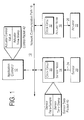
- FIG. 1 illustrates one embodiment of a real-time control system 10 that provides accurate timing information for sensor data samples and accurate timing for the application of control values to actuators in the face of non-deterministic communication.
- the real-time control system 10 includes an application controller 12, a sensor node 14 and an actuator node 16.
- the sensor node 14 includes circuitry that enables accurate time-stamping of sensor data samples of a sensor 20.
- the actuator node 16 includes circuitry that enables the accurate application of control values to an actuator 22.
- the network communication path 18 may be implemented with one of a variety of communication mechanisms.
- the network communication path 18 is an Ethernet communication network.
- the network communication path 18 is a LonTalk field-level control bus which is specialized for the process control environment.
- the network communication path 18 may be implemented with time division multiple access (TDMA) or token ring protocols to name only a few possibilities.
- TDMA time division multiple access
- the sensor 20 represents any sensor that may be employed in a real-time control system. Such sensors include for example devices such as temperature sensors, pressure sensors, and tachometers.
- the actuator 20 represents any actuator that may be employed in a real-time control system. Such actuators include for example devices such valves, motors, heaters, and amplifiers.
- the sensor node 14 interfaces the sensor 20 to the network communication path 18.
- the sensor node 14 includes the communication hardware and software necessary for communication via the network communication path 18.
- the sensor node 14 also includes a clock circuit 30 that enables accurate time-stamping of sensor data samples obtained from a sensor 20.
- the actuator node 16 interfaces the actuator 22 to the network communication path 18.
- the actuator node includes the communication hardware and software necessary for communication via the network communication path 18.
- the actuator node 16 also includes a clock circuit 32 that enables the accurate application of control values to an actuator 22.
- the clock circuits 30 and 32 are synchronized by transferring time packets via the network communication path 18 and providing the sensor node 14 and the actuator node 16 with time packet detectors in a manner described in U.S. Patent No. 5,566,180.
- the application controller 12 implements a process control algorithm for closed loop control of a device (not shown).
- the application controller 12 senses the performance of the device using the sensor 20 and controls the performance of the device using the actuator 22.
- the device may be a motor and the actuator 22 may be an amplifier that controls the speed of the motor and the sensor 20 a tachometer that measures the speed of the motor.
- the application controller 12 includes the communication hardware and software, i.e. protocol stack, necessary for communication via the network communication path 18.
- the application controller 12 may be implemented as programmable logic controller (PLC) or as a computer system.
- PLC programmable logic controller
- the sensor node 14 generates a sensor data sample by sampling a sensor data signal 24 from the sensor 20. At the same time the sensor node 14 obtains a sensor time-stamp from the clock circuit 30. The sensor time-stamp is obtained form the clock circuit 30 substantially contemporaneously with the sampling of the sensor data signal 24 in order to provide an accurate sensor time-stamp.
- the sensor node 14 samples the sensor data signal 24 in response to a request message for sensor data that is received via the network communication path 18.
- a pull system in that an external node pulls data from the sensor node 14.
- the request for sensor data may originate with the application controller 12 or with the actuator node 16.
- the sensor node 14 generates a sensor data packet 40.
- the sensor data packet 14 includes the sensor data sample obtained from the sensor 20 and the sensor time-stamp obtained from the clock circuit 30.
- the sensor node 14 transfers the sensor data packet 40 via the network communication path 18.
- the sensor data packet 40 in a pull system is transferred to the node on the network communication path 18 that issued the request for sensor data which may be either the application controller 12 or the actuator node 16.
- the sensor node 14 samples the sensor data signal 24 and obtains a corresponding sensor time-stamp without any request messages.
- This embodiment may be referred to as a push system.
- the sensor node 14 is preprogrammed to periodically obtain sensor data samples and sensor-time stamps.
- the sensor node 14 periodically transfers the sensor data packet 40 containing newly obtained sensor data samples and sensor time-stamps over the network communication path 18 to either the application controller 12 or the actuator node 16.
- the application controller 12 implements the process control algorithm.
- the application controller 12 receives the sensor data packet 40 via the communication path 18 and uses the sensor data sample and sensor time-stamp contained therein as inputs to its process control algorithm.
- the process control algorithm generates an actuator control value and a corresponding actuator time-stamp which indicates a future time at which the actuator control value is to be applied to the actuator 22.
- the application controller 12 assembles actuator control value and actuator time-stamp into a control packet 42.
- the application controller 12 then transfers the control packet 42 to the actuator node 16 via the network communication path 18.
- the actuator node 16 receives the control packet 42 via the network communication path 18 and uses the actuator time-stamp contained therein as a triggering event for applying the actuator control value to the actuator 22 as an actuator signal 26.
- the actuator node 16 synchronizes the application of the actuator control value to the actuator time-stamp using the clock circuit 32.
- the clock circuit 32 is synchronized to the clock circuit 30 and the application controller 12 derives the actuator time-stamp from the sensor time-stamp which was generated by the clock circuit 30.
- the process control system 10 shown depicts an embodiment in which the application controller 12 obtains sensor data samples and time-stamps from the sensor node 14 via the network communication path 18, computes actuator control values and actuator time-stamps, and then transfers the actuator control values and time-stamps to the actuator node 16 via the communication path 18.
- the process control algorithm may be implemented in the actuator node 16 which includes a processor and other software execution resources.
- the actuator node 16 obtains sensor data samples and time-stamps from the sensor node 14 via the communication path 18, computes actuator control values and time-stamps, and applies the actuator control values to the actuator 22.
- the process control algorithm for the device attached to the actuator 22 is implemented in the sensor node 14 which includes a processor and other software execution resources.
- the sensor node 14 obtains sensor data samples and time-stamps, computes actuator control values and time-stamps, and then transfers the actuator control values and time-stamps to the actuator node 16 via the network communication path 18.
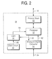
- FIG. 2 illustrates mechanisms in the sensor node 14 for accurately time-stamping sensor data samples in one embodiment.
- the sensor node 14 includes a processor 52 that obtains a sensor data sample 62 from an analog-to-digital converter 54 and a sensor time-stamp 64 from the clock circuit 30 and then assembles the sensor data packet 40.
- the sensor node 14 also includes a protocol stack 50 which includes the software and hardware elements that enable communication via the network communication path 18.
- the analog-to-digital converter 54 is coupled to receive the analog sensor data signal 24 from the sensor 20.
- the analog-to-digital converter 54 generates the sensor data sample 62 by digitizing the sensor data signal 24 in response to a strobe signal 60 generated by the processor 52.
- the analog-to-digital converter 54 holds the sensor data sample 62 for subsequent reading by the processor 52.
- the strobe signal 60 also causes a latch 56 to sample and hold a clock value 66 from the clock circuit 30.
- the strobe signal 60 causes the latch 56 to sample the clock value 66 substantially contemporaneously with the sampling of the sensor data signal 24 by the analog-to-digital converter 54.
- the processor 52 issues the strobe signal 60 to sample the clock value 66 and the sensor data signal 24 in response to a request message received via the network communication path 18. In another embodiment, the processor 52 periodically issues the strobe signal 60 to sample the clock value 66 and the sensor data signal 24. For example, the processor 52 may read or "poll" the clock value 66 to determine when another set of samples of the clock value 66 and the sensor data signal 24 should be obtained.
- the processor 52 reads the sensor data sample 62 held by the analog-to-digital converter 54 and writes it into the sensor data packet 40. In addition, the processor 52 reads the sensor time-stamp 64 held by the latch 56 and writes it into the sensor data packet 40. The processor 52 then transfers the sensor data packet 40 over the network communication path 18 using the protocol stack 50. The sensor data packet 40 in pull system is transferred to the requesting node, for example the application controller 12. In a push system, the processor 52 transfers the sensor data packet 40 to either the application controller 12 or the actuator node 16 whichever is predetermined to be the target.
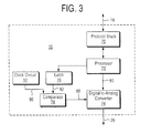
- Figure 3 illustrates one embodiment of a mechanism in the actuator node 16 for accurately applying actuator control values to the actuator 22.
- the actuator node 16 includes a protocol stack 70 which includes the software and hardware elements that enable communication via the network communication path 18.
- the actuator node 16 also includes a processor 72 that receives the control packet 42 via the network communication path 18 using the protocol stack 70.
- the processor 72 writes the actuator control value from the control packet 42 to a digital-to-analog converter 74 as a control value 80.
- the digital-to-analog converter 74 holds the control value 80 until a strobe signal 88 is asserted by a comparator 78.
- the processor 72 writes the actuator time-stamp contained in the control packet 42 into a latch 76.
- the comparator 78 compares a latched actuator time-stamp 82 with a free running clock value 86 generated by the clock circuit 32.
- the comparator 78 asserts the strobe signal 88 when the free running clock value 86 reaches the latched actuator time-stamp 82.
- the strobe signal 88 causes the digital-to-analog converter 74 to convert the control value 80 into an actuator control signal 26 for the actuator 22.
- the triggering function provided by the comparator 78 is instead performed in firmware, for example, with a compare instruction executed by the processor 72.
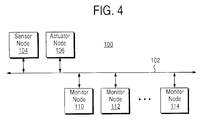
- FIG. 4 shows a process control network 100 which implements methods for handling event storms.
- the process control network 100 includes a sensor node 104 and an actuator node 106 that together implement a control loop.
- the sensor node 104 and the actuator node 106 each include a synchronized clock circuit and the hardware and software elements for communication via a network communication path 102.
- the sensor node 104 periodically transfers a sensor data packet containing a sensor data sample and a corresponding sensor time-stamp to the actuator node 106 via the network communication path 102.
- the sensor node 104 and the actuator node 106 provide a pull system in which the actuator node 106 periodically transfers a request messages to the sensor node 104 via the network communication path 102.
- the sensor node 104 responds to each request message by obtaining a sensor data sample and a corresponding sensor time-stamp and transferring them in a sensor data packet via the network communication path 102.
- the sensor node 104 and the actuator node 106 provide a push system in which the sensor node 104 periodically obtains a sensor data sample and a corresponding sensor time-stamp and transfers them in a sensor data packet via the network communication path 102.
- the process control network 100 includes a set of monitor nodes 110-114. Each of the monitor nodes 110-114 performs a monitoring function to detect an unusual event or alarm in the process control network 100. These alarms may be, for example, over-temperature alarms or other events that must be communicated to other parts of the process control network 100.
- a condition may occur in the process control network 100 which may be referred to as an event storm.
- An event storm may occur, for example, when a large number of the monitor nodes 110-114 detect an unusual event.
- the monitor nodes 110-114 that detect an unusual event transfer alarm messages via the network communication path 102 to notify other parts of the process control network 100 of the unusual events.
- the large number of alarm messages transferred via the network communication path 102 during an event storm can consume most of the available bandwidth of the network communication path 102. These event storms can cause large numbers of collisions and the resulting collision arbitration mechanism on the network communication path 102 can slow overall throughput in the process control network 100. As a consequence, the messages required to maintain the control loop between the sensor node 104 and the actuator ncde 106 can become delayed or even lost or transferred out of order.
- the sensor time-stamps contained in the sensor data packets transferred over the network communication path 102 enable the detection of delayed or missing or out of order sensor data packets. For example, assume the control loop between the sensor node 104 and the actuator node 106 includes the sampling of sensor data every t0 seconds. If so, then a sensor data packet should be transferred via the network communication path 102 approximately every t0 seconds and the sensor time-stamp contained in each sensor data packet should differ from a previous one by approximately t0 seconds. If two consecutive sensor data packets carried on the network communication path 102 have time-stamp values that differ by significantly more than t0 seconds then it is an indication that sensor data packets are being delayed or lost possibly due to an event storm.
- any one or more of the actuator node 106 and the monitor nodes 110-114 may use the sensor time-stamps in the sensor data packets transferred via the network communication path 102 to detect event storms.
- the actuator node 106 as the target already receives the sensor data packets and extracts the sensor time-stamps to compute actuator control values.
- the monitor nodes 110-114 can monitor or "snoop" the network communication path 102 for sensor data packets and record the sensor time-stamps to detect delayed or missing sensor data packets.
- the monitor node 110 if for example the monitor node 110 detects delayed or missing sensor data packets that may signal an event storm it stops transferring monitor messages on the communication path 102 for a predetermined time period. In another embodiment, the monitor node 110 transfers an emergency notification message via the communication path 102 if it detects a possible event storm. The emergency notification message causes the remaining monitor nodes 112-114 to stop transferring messages on the communication path 102 for a predetermined time period.
- Another method for detecting possible event storms involves the detection of collisions on the network communication path 102 for embodiments where the network communication path 102 provides collision handling such as Ethernet.
- the protocol stack i.e. the communication hardware and software, in the sensor node 104 includes a mechanism for logging the occurrence of collisions on the network communication path 102.
- the processor in the sensor node 104 periodically queries the corresponding protocol stack to determine whether excessive numbers of collisions are occurring which could indicate an event storm.
- the protocol stack in the sensor node 104 includes a outbound message queue for buffering messages for transfer via the network communication path 102.
- the processor in the sensor node 104 periodically checks the outbound message queue. A nearly full outbound message queue could indicate that an event storm is underway.
- the sensor node 104 and the actuator node 106 run their control loop in a reduced performance mode if an event storm is detected.
- the sensor node 104 provides sensor data samples every t0/K seconds where K is a constant rather than the t0 samples per second in a normal state without an event storm.
- the reduced state reduces the bandwidth utilization on the network communication path 102 required to maintain the control loop.
- the sensor node 104 and the actuator node 106 put the control loop into a "safe" state if an event storm is detected.
- the safe state may correspond to the last control value successfully received by the actuator node 106.
- the actuator node 106 may turn off the actuator once an event storm is detected.
- the monitor nodes 110-114 may take a variety of actions once an event storm is detected. For example, the monitor nodes 110-114 can stop transferring messages on the network communication path 102, including alarm messages, for a period of time. The monitor nodes 110-114 may continue to obtain monitoring data and may include synchronized clock circuits that enable the monitor data to be accurately time-stamped. This would enable the monitor nodes 110-114 to transfer the buffered monitor data and time-stamps via the network communication path 102 once the event storms end and allow a receiving node to reconstruct the monitor data with accurate timing information. Alternatively, the monitor nodes 110-114 can reduce that rate at which they transfer messages on the network communication path 102 for a period of time during an event storm.
Abstract
Description
- The present invention pertains to the field of control systems. More particularly, this invention relates to real-time control systems that employ non-deterministic communication.
- Real-time control systems commonly include sensors and actuators and application controllers which are arranged to provide control of devices including devices used in industrial processes. Such sensors may include temperature sensors, pressure sensors, tachometers, etc. Such actuators may include, valves, motors, heaters etc. Application controllers in such a control system may be implemented with programmable logic controllers (PLCs) or computer systems including personal computer systems.
- A real-time control system in its simplest form includes an application controller, at least one sensor, and at least one actuator. Typically, the application controller implements a control algorithm which is adapted to maintain a set point for a particular device being controlled. Typically, the application controller obtains sensor data samples from the sensor and uses the sensor data samples as inputs to a control algorithm which computes a control value to be applied to the actuator. The application controller then usually writes the control value to the actuator. Typically, the application controller continually obtains sensor data samples and continually provides control values to the actuator in order to maintain a desired set point. Such an arrangement may be referred to as a closed-loop control system.
- For example, a simple real-time control system for a motor may include a tachometer (sensor) that measures the rotational speed of the motor and an amplifier circuit (actuator) that increases or decreases the rotational speed of the motor in response to a control value applied to the amplifier circuit. An application controller periodically obtains rotational speed samples from the tachometer and periodically writes control values to the amplifier circuit in order to maintain the desired set point for the speed of the motor.
- A typical control algorithm for such a real-time control system typically uses timing information together with sensor data samples to compute control values. In addition, such a control algorithm usually associates timing information with each control value. One such type of control algorithm is referred to as a proportional integral derivative (PID) algorithm. A PID algorithm usually takes as input a time value associated with each sensor data sample. The time values enable the PID algorithm to take into account the rate of change of the sensor data samples when computing a new control value. In addition, the PID algorithm usually assigns a time value to each new control value which indicates a time at which the new control value is to be applied to the actuator.
- As a consequence, a real-time control system must usually provide accurate timing information for each sensor data sample in order to render accurate computation of control values. In addition, a real-time control system must typically apply each control value to the actuator with accurate timing in order to provide accurate control of the desired set point. Unfortunately, prior control systems commonly suffer from inaccuracies in the relationship between the sensor data samples and their associated timing information. In addition, inaccuracies commonly exist as to the time that a control value is applied to an actuator in prior systems. In general, such uncertainties are caused by the non-deterministic nature of communication that is commonly employed in prior real-time control systems.
- For example, the sensors, actuators, and controllers in prior real-time control systems are commonly interconnected via a communication network. Such a communication network may be implemented with a packet-based communication protocol that includes collision handling. Ethernet is an example of a packet-based network with collision handling. Another example is LonTalk which is a field-level control bus specialized for the process control environment. Such a communication network may also be implemented with time division multiple access (TDMA) or token ring protocols to name a few.
- An application controller connected to such a communication network typically obtains sensor data samples using messages transferred over the communication network. Typically, the application controller includes a real-time clock which is used to assign a time value to each sensor data sample received over the communication network.
- Typically, a delay exists between the time a sensor data sample is generated and the time an application controller obtains a time value for that sensor data sample from its real-time clock. Such delay usually includes the delay associated with message transfer over the communication path. Such delay also typically includes the delay associated with the application controller obtaining a time value from its real-time clock.
- In addition, a delay usually exists between the time the time that an application controller generates a control value and the time that the control value is applied to an actuator. Such delay usually includes the delay associated with message transfer over the communication path to the actuator as well as the delay in the actuator before the control value is applied.
- Such delays, both in sensor data timing and in the application of control values, are usually not constant. Instead, such delays typically vary in a non-deterministic or random manner. Such variation in delay may be referred to as jitter. Jitter may be caused by the variation of traffic on the communication network. In addition, collisions that occur on the communication network can introduce substantial amounts of jitter. Other sources of jitter may include variation in the time taken by an operating system, under which the application controller usually runs, to render a real-time clock value in the face of varying amounts of operating system activity.
- Unfortunately, such jitter usually creates inaccuracies in associating time values to sensor data samples. Such jitter also typically creates inaccuracies in the timing of the application of the control values to actuators. Such inaccuracies typically decreases the accuracy and efficiency of such prior control systems.
- A control system is disclosed that provides accurate timing information for sensor data samples and accurate timing for the application of control values to actuators in the face of non-deterministic communication. The control system includes a sensor node with circuitry that generates a sensor time-stamp substantially contemporaneously with a time at which it obtains a sensor data sample. The sensor time-stamp enables accurate computation of an actuator control value and an actuator time-stamp. The control system includes an actuator node having circuitry for triggering the application of the actuator control value to an actuator using the actuator time-stamp.
- Other features and advantages of the present invention will be apparent from the detailed description that follows.
- The present invention is described with respect to particular exemplary embodiments thereof and reference is accordingly made to the drawings in which:
- Figure 1 illustrates one embodiment of a real-time control system that provides accurate timing information for sensor data samples and accurate timing for the application of control values to actuators in the face of non-deterministic communication;
- Figure 2 illustrates one embodiment of mechanisms in a sensor node for accurately time-stamping sensor data samples;
- Figure 3 illustrates one embodiment of a mechanism in an actuator node for accurately applying actuator control values to the actuator;
- Figure 4 shows a process control network which implements methods for handling event storms.
-
- Figure 1 illustrates one embodiment of a real-
time control system 10 that provides accurate timing information for sensor data samples and accurate timing for the application of control values to actuators in the face of non-deterministic communication. The real-time control system 10 includes anapplication controller 12, asensor node 14 and anactuator node 16. Thesensor node 14 includes circuitry that enables accurate time-stamping of sensor data samples of asensor 20. Theactuator node 16 includes circuitry that enables the accurate application of control values to anactuator 22. - The
network communication path 18 may be implemented with one of a variety of communication mechanisms. In one embodiment, thenetwork communication path 18 is an Ethernet communication network. In another embodiment, thenetwork communication path 18 is a LonTalk field-level control bus which is specialized for the process control environment. In other embodiments, thenetwork communication path 18 may be implemented with time division multiple access (TDMA) or token ring protocols to name only a few possibilities. - The
sensor 20 represents any sensor that may be employed in a real-time control system. Such sensors include for example devices such as temperature sensors, pressure sensors, and tachometers. Theactuator 20 represents any actuator that may be employed in a real-time control system. Such actuators include for example devices such valves, motors, heaters, and amplifiers. - The
sensor node 14 interfaces thesensor 20 to thenetwork communication path 18. Thesensor node 14 includes the communication hardware and software necessary for communication via thenetwork communication path 18. Thesensor node 14 also includes aclock circuit 30 that enables accurate time-stamping of sensor data samples obtained from asensor 20. - The
actuator node 16 interfaces theactuator 22 to thenetwork communication path 18. The actuator node includes the communication hardware and software necessary for communication via thenetwork communication path 18. Theactuator node 16 also includes aclock circuit 32 that enables the accurate application of control values to anactuator 22. In one embodiment, theclock circuits network communication path 18 and providing thesensor node 14 and theactuator node 16 with time packet detectors in a manner described in U.S. Patent No. 5,566,180. - The
application controller 12 implements a process control algorithm for closed loop control of a device (not shown). Theapplication controller 12 senses the performance of the device using thesensor 20 and controls the performance of the device using theactuator 22. For example, the device may be a motor and theactuator 22 may be an amplifier that controls the speed of the motor and the sensor 20 a tachometer that measures the speed of the motor. Theapplication controller 12 includes the communication hardware and software, i.e. protocol stack, necessary for communication via thenetwork communication path 18. Theapplication controller 12 may be implemented as programmable logic controller (PLC) or as a computer system. - The
sensor node 14 generates a sensor data sample by sampling a sensor data signal 24 from thesensor 20. At the same time thesensor node 14 obtains a sensor time-stamp from theclock circuit 30. The sensor time-stamp is obtained form theclock circuit 30 substantially contemporaneously with the sampling of the sensor data signal 24 in order to provide an accurate sensor time-stamp. In one embodiment, thesensor node 14 samples the sensor data signal 24 in response to a request message for sensor data that is received via thenetwork communication path 18. Such an embodiment may be referred to as a pull system in that an external node pulls data from thesensor node 14. The request for sensor data may originate with theapplication controller 12 or with theactuator node 16. - The
sensor node 14 generates asensor data packet 40. Thesensor data packet 14 includes the sensor data sample obtained from thesensor 20 and the sensor time-stamp obtained from theclock circuit 30. Thesensor node 14 transfers thesensor data packet 40 via thenetwork communication path 18. Thesensor data packet 40 in a pull system is transferred to the node on thenetwork communication path 18 that issued the request for sensor data which may be either theapplication controller 12 or theactuator node 16. - In another embodiment, the
sensor node 14 samples the sensor data signal 24 and obtains a corresponding sensor time-stamp without any request messages. This embodiment may be referred to as a push system. In a push system, thesensor node 14 is preprogrammed to periodically obtain sensor data samples and sensor-time stamps. Thesensor node 14 periodically transfers thesensor data packet 40 containing newly obtained sensor data samples and sensor time-stamps over thenetwork communication path 18 to either theapplication controller 12 or theactuator node 16. - In the following discussion it is assumed that the
application controller 12 implements the process control algorithm. Theapplication controller 12 receives thesensor data packet 40 via thecommunication path 18 and uses the sensor data sample and sensor time-stamp contained therein as inputs to its process control algorithm. The process control algorithm generates an actuator control value and a corresponding actuator time-stamp which indicates a future time at which the actuator control value is to be applied to theactuator 22. Theapplication controller 12 assembles actuator control value and actuator time-stamp into a control packet 42. Theapplication controller 12 then transfers the control packet 42 to theactuator node 16 via thenetwork communication path 18. - The
actuator node 16 receives the control packet 42 via thenetwork communication path 18 and uses the actuator time-stamp contained therein as a triggering event for applying the actuator control value to theactuator 22 as anactuator signal 26. Theactuator node 16 synchronizes the application of the actuator control value to the actuator time-stamp using theclock circuit 32. Theclock circuit 32 is synchronized to theclock circuit 30 and theapplication controller 12 derives the actuator time-stamp from the sensor time-stamp which was generated by theclock circuit 30. - The
process control system 10 shown depicts an embodiment in which theapplication controller 12 obtains sensor data samples and time-stamps from thesensor node 14 via thenetwork communication path 18, computes actuator control values and actuator time-stamps, and then transfers the actuator control values and time-stamps to theactuator node 16 via thecommunication path 18. In another embodiment, the process control algorithm may be implemented in theactuator node 16 which includes a processor and other software execution resources. In such an embodiment, theactuator node 16 obtains sensor data samples and time-stamps from thesensor node 14 via thecommunication path 18, computes actuator control values and time-stamps, and applies the actuator control values to theactuator 22. - In yet another embodiment, the process control algorithm for the device attached to the
actuator 22 is implemented in thesensor node 14 which includes a processor and other software execution resources. In such an embodiment, thesensor node 14 obtains sensor data samples and time-stamps, computes actuator control values and time-stamps, and then transfers the actuator control values and time-stamps to theactuator node 16 via thenetwork communication path 18. - Figure 2 illustrates mechanisms in the
sensor node 14 for accurately time-stamping sensor data samples in one embodiment. Thesensor node 14 includes aprocessor 52 that obtains asensor data sample 62 from an analog-to-digital converter 54 and a sensor time-stamp 64 from theclock circuit 30 and then assembles thesensor data packet 40. Thesensor node 14 also includes aprotocol stack 50 which includes the software and hardware elements that enable communication via thenetwork communication path 18. - The analog-to-
digital converter 54 is coupled to receive the analog sensor data signal 24 from thesensor 20. The analog-to-digital converter 54 generates thesensor data sample 62 by digitizing the sensor data signal 24 in response to astrobe signal 60 generated by theprocessor 52. The analog-to-digital converter 54 holds thesensor data sample 62 for subsequent reading by theprocessor 52. Thestrobe signal 60 also causes alatch 56 to sample and hold aclock value 66 from theclock circuit 30. Thestrobe signal 60 causes thelatch 56 to sample theclock value 66 substantially contemporaneously with the sampling of the sensor data signal 24 by the analog-to-digital converter 54. - In one embodiment, the
processor 52 issues thestrobe signal 60 to sample theclock value 66 and the sensor data signal 24 in response to a request message received via thenetwork communication path 18. In another embodiment, theprocessor 52 periodically issues thestrobe signal 60 to sample theclock value 66 and the sensor data signal 24. For example, theprocessor 52 may read or "poll" theclock value 66 to determine when another set of samples of theclock value 66 and the sensor data signal 24 should be obtained. - The
processor 52 reads thesensor data sample 62 held by the analog-to-digital converter 54 and writes it into thesensor data packet 40. In addition, theprocessor 52 reads the sensor time-stamp 64 held by thelatch 56 and writes it into thesensor data packet 40. Theprocessor 52 then transfers thesensor data packet 40 over thenetwork communication path 18 using theprotocol stack 50. Thesensor data packet 40 in pull system is transferred to the requesting node, for example theapplication controller 12. In a push system, theprocessor 52 transfers thesensor data packet 40 to either theapplication controller 12 or theactuator node 16 whichever is predetermined to be the target. - Figure 3 illustrates one embodiment of a mechanism in the
actuator node 16 for accurately applying actuator control values to theactuator 22. Theactuator node 16 includes aprotocol stack 70 which includes the software and hardware elements that enable communication via thenetwork communication path 18. Theactuator node 16 also includes aprocessor 72 that receives the control packet 42 via thenetwork communication path 18 using theprotocol stack 70. - The
processor 72 writes the actuator control value from the control packet 42 to a digital-to-analog converter 74 as acontrol value 80. The digital-to-analog converter 74 holds thecontrol value 80 until astrobe signal 88 is asserted by acomparator 78. In addition, theprocessor 72 writes the actuator time-stamp contained in the control packet 42 into alatch 76. - The
comparator 78 compares a latched actuator time-stamp 82 with a freerunning clock value 86 generated by theclock circuit 32. Thecomparator 78 asserts thestrobe signal 88 when the freerunning clock value 86 reaches the latched actuator time-stamp 82. Thestrobe signal 88 causes the digital-to-analog converter 74 to convert thecontrol value 80 into anactuator control signal 26 for theactuator 22. - In another embodiment, the triggering function provided by the
comparator 78 is instead performed in firmware, for example, with a compare instruction executed by theprocessor 72. - Figure 4 shows a
process control network 100 which implements methods for handling event storms. Theprocess control network 100 includes asensor node 104 and anactuator node 106 that together implement a control loop. Thesensor node 104 and theactuator node 106 each include a synchronized clock circuit and the hardware and software elements for communication via anetwork communication path 102. Thesensor node 104 periodically transfers a sensor data packet containing a sensor data sample and a corresponding sensor time-stamp to theactuator node 106 via thenetwork communication path 102. - In one embodiment, the
sensor node 104 and theactuator node 106 provide a pull system in which theactuator node 106 periodically transfers a request messages to thesensor node 104 via thenetwork communication path 102. Thesensor node 104 responds to each request message by obtaining a sensor data sample and a corresponding sensor time-stamp and transferring them in a sensor data packet via thenetwork communication path 102. In another embodiment, thesensor node 104 and theactuator node 106 provide a push system in which thesensor node 104 periodically obtains a sensor data sample and a corresponding sensor time-stamp and transfers them in a sensor data packet via thenetwork communication path 102. - The
process control network 100 includes a set of monitor nodes 110-114. Each of the monitor nodes 110-114 performs a monitoring function to detect an unusual event or alarm in theprocess control network 100. These alarms may be, for example, over-temperature alarms or other events that must be communicated to other parts of theprocess control network 100. - A condition may occur in the
process control network 100 which may be referred to as an event storm. An event storm may occur, for example, when a large number of the monitor nodes 110-114 detect an unusual event. The monitor nodes 110-114 that detect an unusual event transfer alarm messages via thenetwork communication path 102 to notify other parts of theprocess control network 100 of the unusual events. - The large number of alarm messages transferred via the
network communication path 102 during an event storm can consume most of the available bandwidth of thenetwork communication path 102. These event storms can cause large numbers of collisions and the resulting collision arbitration mechanism on thenetwork communication path 102 can slow overall throughput in theprocess control network 100. As a consequence, the messages required to maintain the control loop between thesensor node 104 and theactuator ncde 106 can become delayed or even lost or transferred out of order. - The sensor time-stamps contained in the sensor data packets transferred over the
network communication path 102 enable the detection of delayed or missing or out of order sensor data packets. For example, assume the control loop between thesensor node 104 and theactuator node 106 includes the sampling of sensor data every t0 seconds. If so, then a sensor data packet should be transferred via thenetwork communication path 102 approximately every t0 seconds and the sensor time-stamp contained in each sensor data packet should differ from a previous one by approximately t0 seconds. If two consecutive sensor data packets carried on thenetwork communication path 102 have time-stamp values that differ by significantly more than t0 seconds then it is an indication that sensor data packets are being delayed or lost possibly due to an event storm. - Any one or more of the
actuator node 106 and the monitor nodes 110-114 may use the sensor time-stamps in the sensor data packets transferred via thenetwork communication path 102 to detect event storms. Theactuator node 106 as the target already receives the sensor data packets and extracts the sensor time-stamps to compute actuator control values. In addition, the monitor nodes 110-114 can monitor or "snoop" thenetwork communication path 102 for sensor data packets and record the sensor time-stamps to detect delayed or missing sensor data packets. - In one embodiment, if for example the
monitor node 110 detects delayed or missing sensor data packets that may signal an event storm it stops transferring monitor messages on thecommunication path 102 for a predetermined time period. In another embodiment, themonitor node 110 transfers an emergency notification message via thecommunication path 102 if it detects a possible event storm. The emergency notification message causes the remaining monitor nodes 112-114 to stop transferring messages on thecommunication path 102 for a predetermined time period. - Another method for detecting possible event storms involves the detection of collisions on the
network communication path 102 for embodiments where thenetwork communication path 102 provides collision handling such as Ethernet. For example, the protocol stack, i.e. the communication hardware and software, in thesensor node 104 includes a mechanism for logging the occurrence of collisions on thenetwork communication path 102. The processor in thesensor node 104 periodically queries the corresponding protocol stack to determine whether excessive numbers of collisions are occurring which could indicate an event storm. - In another embodiment, the protocol stack in the
sensor node 104 includes a outbound message queue for buffering messages for transfer via thenetwork communication path 102. The processor in thesensor node 104 periodically checks the outbound message queue. A nearly full outbound message queue could indicate that an event storm is underway. - In one embodiment, the
sensor node 104 and theactuator node 106 run their control loop in a reduced performance mode if an event storm is detected. In one embodiment of a reduced state, thesensor node 104 provides sensor data samples every t0/K seconds where K is a constant rather than the t0 samples per second in a normal state without an event storm. The reduced state reduces the bandwidth utilization on thenetwork communication path 102 required to maintain the control loop. - In another embodiment, the
sensor node 104 and theactuator node 106 put the control loop into a "safe" state if an event storm is detected. The safe state may correspond to the last control value successfully received by theactuator node 106. Alternatively, theactuator node 106 may turn off the actuator once an event storm is detected. - The monitor nodes 110-114 may take a variety of actions once an event storm is detected. For example, the monitor nodes 110-114 can stop transferring messages on the
network communication path 102, including alarm messages, for a period of time. The monitor nodes 110-114 may continue to obtain monitoring data and may include synchronized clock circuits that enable the monitor data to be accurately time-stamped. This would enable the monitor nodes 110-114 to transfer the buffered monitor data and time-stamps via thenetwork communication path 102 once the event storms end and allow a receiving node to reconstruct the monitor data with accurate timing information. Alternatively, the monitor nodes 110-114 can reduce that rate at which they transfer messages on thenetwork communication path 102 for a period of time during an event storm. - The foregoing detailed description of the present invention is provided for the purposes of illustration and is not intended to be exhaustive or to limit the invention to the precise embodiment disclosed. Accordingly, the scope of the present invention is defined by the appended claims.
Claims (20)
- A control system comprising a sensor node (14) for interfacing a sensor (20) to a communication path (18), the sensor node (14) having a circuit for obtaining a sensor data sample and substantially contemporaneously generating a sensor time-stamp such that the sensor data sample and the sensor time-stamp enable an accurate computation of an actuator control value to be applied an actuator (22) in the control system.
- The control system of claim 1, wherein the sensor data sample and the sensor time-stamp enable an accurate computation of an actuator time-stamp that indicates a time at which the actuator control value is to be applied to the actuator (22).
- The control system of claim 2, further comprising an actuator node (16) for interfacing the actuator (22) to the communication path (18), the actuator node (16) having a circuit for triggering the application of the actuator control value to the actuator (22) using the actuator time-stamp.
- The control system of claim 3, further comprising an application controller node (12) coupled to receive the sensor data sample and the sensor time-stamp via the communication path (18), the application controller node (12) generating the actuator control value and the actuator time-stamp in response to the sensor data sample and the sensor time-stamp.
- The control system of claim 4, wherein the actuator node (16) receives the actuator control value and the actuator time-stamp via the communication path (18) from the application controller node (12).
- The control system of claim 3, wherein the actuator node (16) includes a processor (72) that generates the actuator control value and the actuator time-stamp in response to the sensor data sample and the sensor time-stamp received via the communication path (18).
- The control system of claim 1, wherein the sensor node (14) obtains the sensor data sample and generates the sensor time-stamp in response to a request message received via the communication path (18).
- The control system of claim 1, rein the sensor node (14) periodically obtains the sensor data sample and generates the sensor time-stamp without a request message being received via the communication path (18).
- The control system of claim 1, wherein the sensor node (14) transfers a series of sensor data packets (40) via the communication path (18), each sensor data packet (40) containing a time-stamp such that the time-stamps carried on the communication path(18) enable the detection of an event storm in the process control system.
- The control system of claim 9, further comprising a monitor node (110) that snoops the communication path (18) and examines the time-stamps to determine whether one or more of the sensor data packets (40) is missing or delayed.
- The control system of claim 10, wherein the monitor node (110) transfers an emergency notification message via the communication path (18) if one or more of the sensor data packets (40) is missing or delayed.
- The control system of claim 11, wherein the emergency notification message causes one or more other nodes on the communication path (18) to stop transmitting messages on the communication path (18) for a predetermined time interval.
- A sensor node for a control system, comprising:circuitry for interfacing a sensor (20) to a communication path (18) of the control system (10);circuitry for obtaining a sensor data sample from the sensor (20) and substantially contemporaneously generating a sensor time-stamp such that the sensor data sample and the sensor time-stamp enable an accurate computation of an actuator control value to be applied an actuator (22) in the control system (10).
- The sensor node of claim 13, wherein the sensor data sample and the sensor time-stamp enable an accurate computation of an actuator time-stamp that indicates a time at which the actuator control value is to be applied to the actuator (22).
- The sensor node of claim 13, wherein the circuitry for obtaining a sensor data sample from the sensor (20) and substantially contemporaneously generating a sensor time-stamp includes a clock circuit (30).
- The sensor node of claim 13, wherein the sensor node (14) obtains the sensor data sample and generates the sensor time-stamp in response to a request message received over the communication path (18).
- The sensor node of claim 13, wherein the sensor node (14) periodically obtains the sensor data sample and generates the sensor time-stamp and then transfers the sensor data sample and the sensor time-stamp over the communication path (18).
- An actuator node for a control system, comprising:circuitry for interfacing an actuator (22) to a communication path (18) of the control system (10);circuitry for triggering the application of an actuator control value to the actuator (22) using an actuator time-stamp.
- The actuator node of claim 18, further comprising means for determining the actuator control value and the actuator time-stamp in response to a sensor data sample and a sensor time-stamp received over the communication path (18).
- The actuator node of claim 18, wherein the circuitry for triggering the application of an actuator control value includes a clock circuit (32).
Applications Claiming Priority (2)
| Application Number | Priority Date | Filing Date | Title |
|---|---|---|---|
| US08/934,792 US6173207B1 (en) | 1997-09-22 | 1997-09-22 | Real-time control system with non-deterministic communication |
| US934792 | 1997-09-22 |
Publications (3)
| Publication Number | Publication Date |
|---|---|
| EP0903655A2 true EP0903655A2 (en) | 1999-03-24 |
| EP0903655A3 EP0903655A3 (en) | 2000-03-15 |
| EP0903655B1 EP0903655B1 (en) | 2003-11-26 |
Family
ID=25466076
Family Applications (1)
| Application Number | Title | Priority Date | Filing Date |
|---|---|---|---|
| EP98307645A Expired - Lifetime EP0903655B1 (en) | 1997-09-22 | 1998-09-21 | Control system with nodes |
Country Status (4)
| Country | Link |
|---|---|
| US (1) | US6173207B1 (en) |
| EP (1) | EP0903655B1 (en) |
| JP (1) | JPH11177554A (en) |
| DE (1) | DE69819992T2 (en) |
Cited By (26)
| Publication number | Priority date | Publication date | Assignee | Title |
|---|---|---|---|---|
| EP1098236A2 (en) * | 1999-11-05 | 2001-05-09 | Robert Bosch Gmbh | Transmission device |
| WO2001043325A1 (en) * | 1999-12-08 | 2001-06-14 | Broadcom Homenetworking, Inc. | Synchronized transport across non-synchronous networks |
| WO2001042864A1 (en) * | 1999-12-07 | 2001-06-14 | Schneider Automation Inc. | Method for adapting a computer-to-computer communication protocol for use in an industrial control system |
| EP1184755A2 (en) * | 2000-08-18 | 2002-03-06 | Siemens Aktiengesellschaft | Method for operating a peripheral unit comprising one main group and at least one input group |
| WO2002021261A2 (en) * | 2000-09-06 | 2002-03-14 | Friedrich-Alexander-Universität Erlangen-Nurnberg | Method for producing computer-assisted real-time systems |
| WO2002076033A2 (en) * | 2001-03-16 | 2002-09-26 | Siemens Aktiengesellschaft | Synchronous, clocked communication system with local input/output components and method for integrating local input/output components into such a system |
| FR2825177A1 (en) * | 2001-04-30 | 2002-11-29 | Luk Lamellen & Kupplungsbau | METHOD FOR CALCULATING GRADIENTS OF SIGNALS TRANSMITTED VIA AN ASYNCHRONOUS TRANSMISSION LINK |
| WO2005017724A2 (en) * | 2003-08-07 | 2005-02-24 | Intel Corporation | Event time-stamping |
| FR2864268A1 (en) * | 2003-12-17 | 2005-06-24 | Neurasis Soc | Automatic process controlling system for industry, has reception module receiving digital data converted into binary configurations by data processing module, and recognition module recognizing pre-identified configurations |
| WO2005091242A2 (en) * | 2004-03-15 | 2005-09-29 | Siemens Aktiengesellschaft | Method for recording signals in a central recording unit |
| GB2418113A (en) * | 2004-09-13 | 2006-03-15 | Agilent Technologies Inc | Synchronizing operations of a plurality of devices via messages over a communication network |
| EP1648104A2 (en) * | 2004-10-15 | 2006-04-19 | Bosch Rexroth AG | Communication system and method of synchronisation of this system |
| WO2006042799A2 (en) * | 2004-10-15 | 2006-04-27 | Siemens Aktiengesellschaft | Method and device for analyzing a technical process |
| EP1659465A2 (en) | 2004-11-23 | 2006-05-24 | Rockwell Automation Technologies, Inc. | Time stamped motion control network protocol that enables balanced single cycle timing and utilization of dynamic data structures |
| EP1684137A2 (en) * | 2005-01-21 | 2006-07-26 | Agilent Technologies, Inc. | Network based triggering in an instrument system |
| WO2007082892A1 (en) | 2006-01-18 | 2007-07-26 | Marposs Societa' Per Azioni | Timing measurement for checking probes |
| WO2007101658A1 (en) * | 2006-03-08 | 2007-09-13 | Pepperl + Fuchs Gmbh | Method for recording input signal variations |
| WO2008105713A1 (en) | 2007-03-01 | 2008-09-04 | Imsys Technologies Ab | Electronic timer system, time control and generation of timing signals |
| EP2085841A1 (en) * | 2008-01-31 | 2009-08-05 | Sick Ag | Sensor with timing element to emit an object detection time |
| US7904184B2 (en) | 2004-11-23 | 2011-03-08 | Rockwell Automation Technologies, Inc. | Motion control timing models |
| CN101552720B (en) * | 2008-04-03 | 2012-10-10 | 余浪 | Method and system for network closed-loop control and interactive acquisition terminal |
| CN103019163A (en) * | 2011-04-11 | 2013-04-03 | 洛克威尔自动控制技术股份有限公司 | Industrial control system with distributed motion planning |
| GB2587576A (en) * | 2014-03-20 | 2021-03-31 | Fisher Rosemount Systems Inc | Reducing controller updates in a control loop |
| WO2021248150A1 (en) * | 2020-06-03 | 2021-12-09 | Microchip Technology Incorporated | Synchronization of elements in a network |
| US11199824B2 (en) | 2012-01-17 | 2021-12-14 | Fisher-Rosemount Systems, Inc. | Reducing controller updates in a control loop |
| CN116872951A (en) * | 2023-09-06 | 2023-10-13 | 福瑞泰克智能系统有限公司 | Multi-sensor data alignment method and device, storage medium and electronic device |
Families Citing this family (27)
| Publication number | Priority date | Publication date | Assignee | Title |
|---|---|---|---|---|
| US6998996B1 (en) * | 1998-12-03 | 2006-02-14 | Agilent Technologies, Inc. | Motion control using time synchronization |
| US7080160B2 (en) * | 2000-04-27 | 2006-07-18 | Qosmetrics, Inc. | Method for creating accurate time-stamped frames sent between computers via a network |
| US7328232B1 (en) * | 2000-10-18 | 2008-02-05 | Beptech Inc. | Distributed multiprocessing system |
| FR2824976B1 (en) * | 2001-05-16 | 2003-08-15 | Nortel Networks Ltd | METHOD FOR ACCOUNTING FOR THE TIME DISTRIBUTION OF A SUCCESSION OF EVENTS |
| EP2495004B1 (en) | 2001-07-31 | 2014-04-16 | Philip Morris Products S.a.s. | Method and apparatus for generating a volatilized material |
| US8984500B2 (en) * | 2004-06-14 | 2015-03-17 | Hewlett-Packard Development Company, L.P. | Programming a computing node connected to a sensor and an actuator |
| US7558687B1 (en) * | 2004-09-02 | 2009-07-07 | Advanced Micro Devices, Inc. | Method and apparatus for dynamic adjustment of a sensor sampling rate |
| US7167776B2 (en) * | 2004-09-02 | 2007-01-23 | Philip Morris Usa Inc. | Method and system for controlling a vapor generator |
| US7573957B2 (en) * | 2005-09-23 | 2009-08-11 | Teradyne, Inc. | Strobe technique for recovering a clock in a digital signal |
| US7856578B2 (en) * | 2005-09-23 | 2010-12-21 | Teradyne, Inc. | Strobe technique for test of digital signal timing |
| US7574632B2 (en) * | 2005-09-23 | 2009-08-11 | Teradyne, Inc. | Strobe technique for time stamping a digital signal |
| WO2007038339A2 (en) | 2005-09-23 | 2007-04-05 | Teradyne, Inc. | Strobe technique for recovering a clock in a digital signal |
| US8325767B2 (en) * | 2006-09-29 | 2012-12-04 | Agilent Technologies, Inc. | Enhancement of IEEE 1588 synchronization using out-of-band communication path |
| US9007181B2 (en) * | 2010-01-08 | 2015-04-14 | Tyco Fire & Security Gmbh | Method and system for discovery and transparent status reporting for sensor networks |
| JP5177239B2 (en) * | 2011-01-21 | 2013-04-03 | 沖電気工業株式会社 | Context-aware system and event data generation method |
| WO2013154337A1 (en) * | 2012-04-09 | 2013-10-17 | 주식회사 싸이트로닉 | Method and system for static and dynamic positioning or controlling motion of marine structure |
| US8949676B2 (en) | 2012-05-11 | 2015-02-03 | International Business Machines Corporation | Real-time event storm detection in a cloud environment |
| US9075545B2 (en) | 2012-08-01 | 2015-07-07 | Hewlett-Packard Development Company, L.P. | Synchronizing sensor data using timestamps and signal interpolation |
| US9485289B2 (en) | 2013-08-28 | 2016-11-01 | Cisco Technology, Inc. | HTTP streaming client adaptation algorithm based on proportional-integral control |
| US9921561B2 (en) * | 2015-03-17 | 2018-03-20 | Secure Cloud Systems, Inc. | Real time control of a remote device |
| US11329963B2 (en) | 2018-02-22 | 2022-05-10 | Eclypses, Inc. | System and method for securely transferring data |
| CN112424709B (en) * | 2018-08-31 | 2024-02-09 | 株式会社安川电机 | Control device of industrial equipment and data acquisition system of industrial equipment |
| US10809760B1 (en) * | 2018-10-29 | 2020-10-20 | Facebook, Inc. | Headset clock synchronization |
| US11405203B2 (en) | 2020-02-17 | 2022-08-02 | Eclypses, Inc. | System and method for securely transferring data using generated encryption keys |
| US11522707B2 (en) | 2021-03-05 | 2022-12-06 | Eclypses, Inc. | System and method for detecting compromised devices |
| US11720693B2 (en) | 2021-03-05 | 2023-08-08 | Eclypses, Inc. | System and method for securely transferring data |
| US20230418689A1 (en) * | 2022-06-22 | 2023-12-28 | Allegro Microsystems, Llc | Methods and apparatus for sensor data consistency |
Citations (6)
| Publication number | Priority date | Publication date | Assignee | Title |
|---|---|---|---|---|
| EP0362971A2 (en) * | 1984-03-01 | 1990-04-11 | Measurex Corporation | Real-time distributed data-base management system |
| EP0415637A2 (en) * | 1989-08-30 | 1991-03-06 | Industrial Technology Institute | Method and apparatus for simulating a factory system |
| WO1992016905A1 (en) * | 1991-03-18 | 1992-10-01 | Echelon Corporation | Programming language structures for use in a network for communicating, sensing and controlling information |
| EP0550809A1 (en) * | 1992-01-08 | 1993-07-14 | Rockwell International Corporation | Control system for distributed sensors and actuators |
| EP0622713A2 (en) * | 1993-04-28 | 1994-11-02 | Allen-Bradley Company | Method and apparatus for exchanging different classes of data during different time intervals |
| US5586305A (en) * | 1994-10-21 | 1996-12-17 | Hewlett-Packard Company | Smart distributed measurement and control system with a flexible architecture |
Family Cites Families (5)
| Publication number | Priority date | Publication date | Assignee | Title |
|---|---|---|---|---|
| US5293374A (en) * | 1989-03-29 | 1994-03-08 | Hewlett-Packard Company | Measurement system control using real-time clocks and data buffers |
| US4975865A (en) * | 1989-05-31 | 1990-12-04 | Mitech Corporation | Method and apparatus for real-time control |
| US5774377A (en) * | 1991-07-30 | 1998-06-30 | Hewlett-Packard Company | Method and apparatus for monitoring a subsystem within a distributed system for providing an archive of events within a certain time of a trap condition |
| US5887029A (en) * | 1994-05-31 | 1999-03-23 | Allen-Bradley Company, Llc | Method of scheduling spatially separated control events with an industrial controller |
| WO1996001979A1 (en) * | 1994-07-07 | 1996-01-25 | Westinghouse Electric Corporation | Apparatus attaching occurrence time to sensor signals |
-
1997
- 1997-09-22 US US08/934,792 patent/US6173207B1/en not_active Expired - Fee Related
-
1998
- 1998-09-03 JP JP10249237A patent/JPH11177554A/en active Pending
- 1998-09-21 DE DE69819992T patent/DE69819992T2/en not_active Expired - Fee Related
- 1998-09-21 EP EP98307645A patent/EP0903655B1/en not_active Expired - Lifetime
Patent Citations (6)
| Publication number | Priority date | Publication date | Assignee | Title |
|---|---|---|---|---|
| EP0362971A2 (en) * | 1984-03-01 | 1990-04-11 | Measurex Corporation | Real-time distributed data-base management system |
| EP0415637A2 (en) * | 1989-08-30 | 1991-03-06 | Industrial Technology Institute | Method and apparatus for simulating a factory system |
| WO1992016905A1 (en) * | 1991-03-18 | 1992-10-01 | Echelon Corporation | Programming language structures for use in a network for communicating, sensing and controlling information |
| EP0550809A1 (en) * | 1992-01-08 | 1993-07-14 | Rockwell International Corporation | Control system for distributed sensors and actuators |
| EP0622713A2 (en) * | 1993-04-28 | 1994-11-02 | Allen-Bradley Company | Method and apparatus for exchanging different classes of data during different time intervals |
| US5586305A (en) * | 1994-10-21 | 1996-12-17 | Hewlett-Packard Company | Smart distributed measurement and control system with a flexible architecture |
Cited By (57)
| Publication number | Priority date | Publication date | Assignee | Title |
|---|---|---|---|---|
| EP1098236A3 (en) * | 1999-11-05 | 2001-10-24 | Robert Bosch Gmbh | Transmission device |
| US6463381B1 (en) | 1999-11-05 | 2002-10-08 | Robert Bosch Gmbh | Device for transferring measured values and measurement times to a processing device |
| EP1098236A2 (en) * | 1999-11-05 | 2001-05-09 | Robert Bosch Gmbh | Transmission device |
| US6952727B1 (en) | 1999-12-07 | 2005-10-04 | Schneider Automation Inc. | Method for adapting a computer-to-computer communication protocol for use in an industrial control system |
| WO2001042864A1 (en) * | 1999-12-07 | 2001-06-14 | Schneider Automation Inc. | Method for adapting a computer-to-computer communication protocol for use in an industrial control system |
| US7359406B2 (en) | 1999-12-08 | 2008-04-15 | Broadcom Corporation | Synchronized transport across non-synchronous networks |
| US6747996B2 (en) | 1999-12-08 | 2004-06-08 | Broadcom Corporation | Synchronized transport across non-synchronous networks |
| WO2001043325A1 (en) * | 1999-12-08 | 2001-06-14 | Broadcom Homenetworking, Inc. | Synchronized transport across non-synchronous networks |
| EP1184755A2 (en) * | 2000-08-18 | 2002-03-06 | Siemens Aktiengesellschaft | Method for operating a peripheral unit comprising one main group and at least one input group |
| EP1184755A3 (en) * | 2000-08-18 | 2006-07-19 | Siemens Aktiengesellschaft | Method for operating a peripheral unit comprising one main group and at least one input group |
| WO2002021261A2 (en) * | 2000-09-06 | 2002-03-14 | Friedrich-Alexander-Universität Erlangen-Nurnberg | Method for producing computer-assisted real-time systems |
| WO2002021261A3 (en) * | 2000-09-06 | 2002-07-18 | Univ Friedrich Alexander Er | Method for producing computer-assisted real-time systems |
| US7085198B2 (en) | 2000-09-06 | 2006-08-01 | Friedrich-Alexander-Universitat Erlangen-Nurnberg | Method for producing computer-assisted real-time systems |
| WO2002076033A2 (en) * | 2001-03-16 | 2002-09-26 | Siemens Aktiengesellschaft | Synchronous, clocked communication system with local input/output components and method for integrating local input/output components into such a system |
| US7280565B2 (en) | 2001-03-16 | 2007-10-09 | Siemens Aktiengesellschaft | Synchronous clocked communication system with decentralized input/output modules and method for linking decentralized input/output modules into such a system |
| WO2002076033A3 (en) * | 2001-03-16 | 2003-10-02 | Siemens Ag | Synchronous, clocked communication system with local input/output components and method for integrating local input/output components into such a system |
| WO2002089433A3 (en) * | 2001-04-30 | 2003-02-27 | Luk Lamellen & Kupplungsbau | Method for determining the gradients of signals transmitted via an asynchronous transmission link |
| FR2825177A1 (en) * | 2001-04-30 | 2002-11-29 | Luk Lamellen & Kupplungsbau | METHOD FOR CALCULATING GRADIENTS OF SIGNALS TRANSMITTED VIA AN ASYNCHRONOUS TRANSMISSION LINK |
| WO2005017724A3 (en) * | 2003-08-07 | 2005-11-17 | Intel Corp | Event time-stamping |
| CN100456201C (en) * | 2003-08-07 | 2009-01-28 | 英特尔公司 | Event time-stamping |
| KR100829643B1 (en) * | 2003-08-07 | 2008-05-19 | 인텔 코오퍼레이션 | Event time-stamping |
| WO2005017724A2 (en) * | 2003-08-07 | 2005-02-24 | Intel Corporation | Event time-stamping |
| FR2864268A1 (en) * | 2003-12-17 | 2005-06-24 | Neurasis Soc | Automatic process controlling system for industry, has reception module receiving digital data converted into binary configurations by data processing module, and recognition module recognizing pre-identified configurations |
| WO2005091242A3 (en) * | 2004-03-15 | 2005-12-01 | Siemens Ag | Method for recording signals in a central recording unit |
| WO2005091242A2 (en) * | 2004-03-15 | 2005-09-29 | Siemens Aktiengesellschaft | Method for recording signals in a central recording unit |
| GB2418113A (en) * | 2004-09-13 | 2006-03-15 | Agilent Technologies Inc | Synchronizing operations of a plurality of devices via messages over a communication network |
| US8930579B2 (en) | 2004-09-13 | 2015-01-06 | Keysight Technologies, Inc. | System and method for synchronizing operations of a plurality of devices via messages over a communication network |
| US7805280B2 (en) | 2004-10-15 | 2010-09-28 | Siemens Aktiengesellschaft | Method and device for analyzing a technical process |
| WO2006042799A3 (en) * | 2004-10-15 | 2006-07-13 | Siemens Ag | Method and device for analyzing a technical process |
| EP1648104A3 (en) * | 2004-10-15 | 2006-06-07 | Bosch Rexroth AG | Communication sytem and method of synchronisation of this system |
| WO2006042799A2 (en) * | 2004-10-15 | 2006-04-27 | Siemens Aktiengesellschaft | Method and device for analyzing a technical process |
| EP1648104A2 (en) * | 2004-10-15 | 2006-04-19 | Bosch Rexroth AG | Communication system and method of synchronisation of this system |
| EP1659465A2 (en) | 2004-11-23 | 2006-05-24 | Rockwell Automation Technologies, Inc. | Time stamped motion control network protocol that enables balanced single cycle timing and utilization of dynamic data structures |
| US7983769B2 (en) | 2004-11-23 | 2011-07-19 | Rockwell Automation Technologies, Inc. | Time stamped motion control network protocol that enables balanced single cycle timing and utilization of dynamic data structures |
| US7904184B2 (en) | 2004-11-23 | 2011-03-08 | Rockwell Automation Technologies, Inc. | Motion control timing models |
| EP1659465A3 (en) * | 2004-11-23 | 2009-11-25 | Rockwell Automation Technologies, Inc. | Time stamped motion control network protocol that enables balanced single cycle timing and utilization of dynamic data structures |
| EP1684137A2 (en) * | 2005-01-21 | 2006-07-26 | Agilent Technologies, Inc. | Network based triggering in an instrument system |
| EP1684137A3 (en) * | 2005-01-21 | 2007-10-03 | Agilent Technologies, Inc. | Network based triggering in an instrument system |
| WO2007082892A1 (en) | 2006-01-18 | 2007-07-26 | Marposs Societa' Per Azioni | Timing measurement for checking probes |
| CN101375568B (en) * | 2006-01-18 | 2011-08-17 | 马波斯S.P.A.公司 | System and method for transmitting signal for representing event |
| US8107554B2 (en) | 2006-01-18 | 2012-01-31 | Marposs Societa' Per Azioni | Timing measurement for checking probes |
| WO2007101658A1 (en) * | 2006-03-08 | 2007-09-13 | Pepperl + Fuchs Gmbh | Method for recording input signal variations |
| WO2008105713A1 (en) | 2007-03-01 | 2008-09-04 | Imsys Technologies Ab | Electronic timer system, time control and generation of timing signals |
| EP2132613A4 (en) * | 2007-03-01 | 2016-05-04 | Qulsar Sweden Ab | Electronic timer system, time control and generation of timing signals |
| EP2085841A1 (en) * | 2008-01-31 | 2009-08-05 | Sick Ag | Sensor with timing element to emit an object detection time |
| CN101552720B (en) * | 2008-04-03 | 2012-10-10 | 余浪 | Method and system for network closed-loop control and interactive acquisition terminal |
| CN103019163B (en) * | 2011-04-11 | 2016-04-20 | 洛克威尔自动控制技术股份有限公司 | There is the industrial control system of distributed motion planning |
| CN103019163A (en) * | 2011-04-11 | 2013-04-03 | 洛克威尔自动控制技术股份有限公司 | Industrial control system with distributed motion planning |
| CN105573192A (en) * | 2011-04-11 | 2016-05-11 | 洛克威尔自动控制技术股份有限公司 | Input module for an industrial controller |
| CN105573192B (en) * | 2011-04-11 | 2018-05-22 | 罗克韦尔自动化技术公司 | For the input module of industrial control unit (ICU) |
| US11199824B2 (en) | 2012-01-17 | 2021-12-14 | Fisher-Rosemount Systems, Inc. | Reducing controller updates in a control loop |
| GB2587576A (en) * | 2014-03-20 | 2021-03-31 | Fisher Rosemount Systems Inc | Reducing controller updates in a control loop |
| GB2587576B (en) * | 2014-03-20 | 2021-06-23 | Fisher Rosemount Systems Inc | Reducing controller updates in a control loop |
| WO2021248150A1 (en) * | 2020-06-03 | 2021-12-09 | Microchip Technology Incorporated | Synchronization of elements in a network |
| US11956101B2 (en) | 2020-06-03 | 2024-04-09 | Microchip Technology Incorporated | Synchronization of elements in a network |
| CN116872951A (en) * | 2023-09-06 | 2023-10-13 | 福瑞泰克智能系统有限公司 | Multi-sensor data alignment method and device, storage medium and electronic device |
| CN116872951B (en) * | 2023-09-06 | 2023-12-05 | 福瑞泰克智能系统有限公司 | Multi-sensor data alignment method and device, storage medium and electronic device |
Also Published As
| Publication number | Publication date |
|---|---|
| EP0903655B1 (en) | 2003-11-26 |
| US6173207B1 (en) | 2001-01-09 |
| JPH11177554A (en) | 1999-07-02 |
| DE69819992T2 (en) | 2004-09-02 |
| DE69819992D1 (en) | 2004-01-08 |
| EP0903655A3 (en) | 2000-03-15 |
Similar Documents
| Publication | Publication Date | Title |
|---|---|---|
| US6173207B1 (en) | Real-time control system with non-deterministic communication | |
| US6654356B1 (en) | Distributed control system architecture based on synchronized clocks | |
| US7280565B2 (en) | Synchronous clocked communication system with decentralized input/output modules and method for linking decentralized input/output modules into such a system | |
| Johannessen | Time synchronization in a local area network | |
| Albert | Comparison of event-triggered and time-triggered concepts with regard to distributed control systems | |
| US20060026314A1 (en) | Communication controller with automatic time stamping | |
| US6535926B1 (en) | Time synchronization system for industrial control network using global reference pulses | |
| JP4767178B2 (en) | System and method for maintaining a common sense of time on a network segment | |
| JP5009795B2 (en) | Communication controller for coordinating the transmission of regular and irregular messages | |
| US6983391B2 (en) | Modular system with synchronized timing | |
| US6983393B2 (en) | Deterministically handling asynchronous events in a time triggered system | |
| EP1717978A1 (en) | Time synchronization, deterministic data delivery and redundancy for cascaded nodes on full duplex ethernet networks | |
| US20030177154A1 (en) | Synchronization of distributed systems | |
| JP2006101539A (en) | Network transfer arrangement | |
| EP2222003B1 (en) | Field control system | |
| JPH07311721A (en) | Method and apparatus for synchronization of time of network | |
| KR20030084984A (en) | Method and device for synchronizing at least one node of a bus system and a corresponding bus system | |
| US10924371B2 (en) | Method for monitoring a first node in a communications network and monitoring system | |
| US6813664B2 (en) | System transmitting data in equidistance cycles using successive synchronization signals for detecting and signaling access violations | |
| US7802150B2 (en) | Ensuring maximum reaction times in complex or distributed safe and/or nonsafe systems | |
| Ambike et al. | Real-time operating environment for networked control systems | |
| CN109428663A (en) | Synchronization mechanism for height sensors interface | |
| Luckinger et al. | AUTOSAR-compliant clock synchronization over CAN using software timestamping | |
| JPH06508460A (en) | How to generate a common time reference for systems with distributed computing units | |
| Wargui et al. | A scheduling approach for decentralized mobile robot control system |
Legal Events
| Date | Code | Title | Description |
|---|---|---|---|
| PUAI | Public reference made under article 153(3) epc to a published international application that has entered the european phase |
Free format text: ORIGINAL CODE: 0009012 |
|
| AK | Designated contracting states |
Kind code of ref document: A2 Designated state(s): DE FR GB |
|
| AX | Request for extension of the european patent |
Free format text: AL;LT;LV;MK;RO;SI |
|
| PUAL | Search report despatched |
Free format text: ORIGINAL CODE: 0009013 |
|
| AK | Designated contracting states |
Kind code of ref document: A3 Designated state(s): AT BE CH CY DE DK ES FI FR GB GR IE IT LI LU MC NL PT SE |
|
| AX | Request for extension of the european patent |
Free format text: AL;LT;LV;MK;RO;SI |
|
| 17P | Request for examination filed |
Effective date: 20000911 |
|
| AKX | Designation fees paid |
Free format text: DE FR GB |
|
| RAP1 | Party data changed (applicant data changed or rights of an application transferred) |
Owner name: AGILENT TECHNOLOGIES, INC. |
|
| RAP1 | Party data changed (applicant data changed or rights of an application transferred) |
Owner name: AGILENT TECHNOLOGIES INC. |
|
| RAP1 | Party data changed (applicant data changed or rights of an application transferred) |
Owner name: AGILENT TECHNOLOGIES INC. A DELAWARE CORPORATION |
|
| RAP1 | Party data changed (applicant data changed or rights of an application transferred) |
Owner name: AGILENT TECHNOLOGIES, INC. (A DELAWARE CORPORATION |
|
| GRAH | Despatch of communication of intention to grant a patent |
Free format text: ORIGINAL CODE: EPIDOS IGRA |
|
| GRAS | Grant fee paid |
Free format text: ORIGINAL CODE: EPIDOSNIGR3 |
|
| GRAA | (expected) grant |
Free format text: ORIGINAL CODE: 0009210 |
|
| AK | Designated contracting states |
Kind code of ref document: B1 Designated state(s): DE FR GB |
|
| REG | Reference to a national code |
Ref country code: GB Ref legal event code: FG4D |
|
| REF | Corresponds to: |
Ref document number: 69819992 Country of ref document: DE Date of ref document: 20040108 Kind code of ref document: P |
|
| ET | Fr: translation filed | ||
| PLBE | No opposition filed within time limit |
Free format text: ORIGINAL CODE: 0009261 |
|
| STAA | Information on the status of an ep patent application or granted ep patent |
Free format text: STATUS: NO OPPOSITION FILED WITHIN TIME LIMIT |
|
| 26N | No opposition filed |
Effective date: 20040827 |
|
| PGFP | Annual fee paid to national office [announced via postgrant information from national office to epo] |
Ref country code: GB Payment date: 20070926 Year of fee payment: 10 |
|
| PGFP | Annual fee paid to national office [announced via postgrant information from national office to epo] |
Ref country code: FR Payment date: 20070917 Year of fee payment: 10 |
|
| PGFP | Annual fee paid to national office [announced via postgrant information from national office to epo] |
Ref country code: DE Payment date: 20081002 Year of fee payment: 11 |
|
| GBPC | Gb: european patent ceased through non-payment of renewal fee |
Effective date: 20080921 |
|
| REG | Reference to a national code |
Ref country code: FR Ref legal event code: ST Effective date: 20090529 |
|
| PG25 | Lapsed in a contracting state [announced via postgrant information from national office to epo] |
Ref country code: FR Free format text: LAPSE BECAUSE OF NON-PAYMENT OF DUE FEES Effective date: 20080930 |
|
| PG25 | Lapsed in a contracting state [announced via postgrant information from national office to epo] |
Ref country code: GB Free format text: LAPSE BECAUSE OF NON-PAYMENT OF DUE FEES Effective date: 20080921 |
|
| PG25 | Lapsed in a contracting state [announced via postgrant information from national office to epo] |
Ref country code: DE Free format text: LAPSE BECAUSE OF NON-PAYMENT OF DUE FEES Effective date: 20100401 |