EP0905574A2 - Controlled moisturization of paper to eliminate curl - Google Patents
Controlled moisturization of paper to eliminate curl Download PDFInfo
- Publication number
- EP0905574A2 EP0905574A2 EP98307479A EP98307479A EP0905574A2 EP 0905574 A2 EP0905574 A2 EP 0905574A2 EP 98307479 A EP98307479 A EP 98307479A EP 98307479 A EP98307479 A EP 98307479A EP 0905574 A2 EP0905574 A2 EP 0905574A2
- Authority
- EP
- European Patent Office
- Prior art keywords
- sheet
- rolls
- pair
- moisture
- toner
- Prior art date
- Legal status (The legal status is an assumption and is not a legal conclusion. Google has not performed a legal analysis and makes no representation as to the accuracy of the status listed.)
- Granted
Links
Images

Classifications
-
- G—PHYSICS
- G03—PHOTOGRAPHY; CINEMATOGRAPHY; ANALOGOUS TECHNIQUES USING WAVES OTHER THAN OPTICAL WAVES; ELECTROGRAPHY; HOLOGRAPHY
- G03G—ELECTROGRAPHY; ELECTROPHOTOGRAPHY; MAGNETOGRAPHY
- G03G15/00—Apparatus for electrographic processes using a charge pattern
- G03G15/65—Apparatus which relate to the handling of copy material
- G03G15/6555—Handling of sheet copy material taking place in a specific part of the copy material feeding path
- G03G15/6573—Feeding path after the fixing point and up to the discharge tray or the finisher, e.g. special treatment of copy material to compensate for effects from the fixing
- G03G15/6576—Decurling of sheet material
-
- G—PHYSICS
- G03—PHOTOGRAPHY; CINEMATOGRAPHY; ANALOGOUS TECHNIQUES USING WAVES OTHER THAN OPTICAL WAVES; ELECTROGRAPHY; HOLOGRAPHY
- G03G—ELECTROGRAPHY; ELECTROPHOTOGRAPHY; MAGNETOGRAPHY
- G03G2215/00—Apparatus for electrophotographic processes
- G03G2215/00362—Apparatus for electrophotographic processes relating to the copy medium handling
- G03G2215/00535—Stable handling of copy medium
- G03G2215/00662—Decurling device
-
- G—PHYSICS
- G03—PHOTOGRAPHY; CINEMATOGRAPHY; ANALOGOUS TECHNIQUES USING WAVES OTHER THAN OPTICAL WAVES; ELECTROGRAPHY; HOLOGRAPHY
- G03G—ELECTROGRAPHY; ELECTROPHOTOGRAPHY; MAGNETOGRAPHY
- G03G2215/00—Apparatus for electrophotographic processes
- G03G2215/00362—Apparatus for electrophotographic processes relating to the copy medium handling
- G03G2215/00535—Stable handling of copy medium
- G03G2215/0067—Damping device
Definitions
- This invention relates generally to a substrate conditioning device for an electrophotographic printing machine and, more particularly, concerns a moisture control system that applies moisture to cut sheets in a full color process printing machine such that sheets reach equilibrium in a relatively uncurled or flat state.
- a photoconductive member is charged to a substantially uniform potential so as to sensitize the surface thereof.
- the charged portion of the photoconductive member is exposed to a light image of an original document being reproduced. Exposure of the charged photoconductive member selectively dissipates the charges thereon in the irradiated areas.
- the latent image is developed by bringing a developer material into contact therewith.
- the developer material comprises toner particles adhering triboelectrically to carrier granules.
- the toner particles are attracted from the carrier granules to the latent image forming a toner powder image on the photoconductive member.
- the toner powder image is then transferred from the photoconductive member to a copy sheet.
- the toner particles are heated to permanently affix the powder image to the copy sheet.
- the foregoing generally describes a typical black and white electrophotographic printing machine.
- an architecture which comprises a plurality of image forming stations.
- One example of the plural image forming station architecture utilizes an image-on-image (IOI) system in which the photoreceptive member is recharged, reimaged and developed for each color separation.
- IIOI image-on-image
- This charging, imaging, developing and recharging, reimaging and developing, all followed by transfer to paper is done in a single revolution of the photoreceptor in so-called single pass machines, while multipass architectures form each color separation with a single charge, image and develop, with separate transfer operations for each color.
- the single pass architecture offers a potential for high throughput.
- US-A-4,652,110 attempts to replenish moisture lost in the fixing process by collecting moisture as it is driven off the copy sheet for reapplication to the sheet at a later time.
- US-A-5,434,029 describes an apparatus and method of preventing the curling of a substrate having toner images electrostatically adhered thereto which substrate has been subjected to heat for the purpose of fixing the toner images to the substrate. Simultaneous constraint of the copy substrate and the application of moisture thereto is effected by passing the substrate through the nip formed by two pressure engaged rollers, one of which is utilized for applying the water to the back side of the substrate as the substrate passes through the aftermentioned nip.
- US-A-5,264,899 describes a system for adding moisture to a copy sheet.
- the toner fixation step of electrostatographic reproduction desiccates paper, which may lead to the formation a wave along the sheet edge.
- a copier/printer comprising: a pair of reservoirs with each of said pair of reservoirs storing a quantity of liquid; first and second generally cylindrical transfer rolls, each having an outer cylindrical surface which can be made to retain a thin film of fluid; first and second generally cylindrical back-up rollers, each having an outer cylindrical surface which can be rubber coated and suited to driving paper; said first and second transfer rolls and said first and second back-up rolls being aligned with respect to one another along their axis so as to define a small gap between said outer cylindrical surfaces; first and second metering rolls with each of said metering rolls in circumferential surface contact with one of said first and second cylindrical transfer rolls for metering a thin film of fluid to said outer surface of said first and second cylindrical transfer rolls; a paper path spanning the distance between said first transfer and back-up rolls and said second transfer and back-up rolls, said paper path supports and guides the sheet between said rolls; a pair of servo motors with one each of said servo motors with one each of said servo motors with
- This embodiment relates to an imaging system which is used to produce color output in a single revolution or pass of a photoreceptor belt but it is also useable with a multiple pass color process system, a single or multiple pass highlight color system and a black and white printing system.
- the printing machine 8 of the present invention uses a charge retentive surface in the form of an Active Matrix (AMAT) photoreceptor belt 10 supported for movement in the direction indicated by arrow 12, for advancing sequentially through the various xerographic process stations.
- the belt is entrained about a drive roller 14, tension roller 16 and fixed roller 18 and the roller 14 is operatively connected to a drive motor 20 for effecting movement of the belt through the xerographic stations.
- AMAT Active Matrix
- a portion of belt 10 passes through charging station A where a corona generating device, indicated generally by the reference numeral 22, charges the photoconductive surface of belt 10 to a relatively high, substantially uniform, preferably negative potential.
- a controller receives the image signals representing the desired output image and processes these signals to convert them to the various color separations of the image which is transmitted to a laser based output scanning device 24 which causes the charge retentive surface to be discharged in accordance with the output from the scanning device.
- the scanning device is a laser Raster Output Scanner (ROS).
- ROS Raster Output Scanner
- the ROS could be replaced by other xerographic exposure devices such as LED arrays.
- the photoreceptor which is initially charged to a voltage V 0 , undergoes dark decay to a level V ddp equal to about -500 volts. When exposed at the exposure station B it is discharged to V expose equal to about -50 volts. Thus after exposure, the photoreceptor contains a monopolar voltage profile of high and low voltages, the former corresponding to charged areas and the latter corresponding to discharged or background areas.
- developer structure indicated generally by the reference numeral 42 utilizing a hybrid jumping development (HJD) system
- the development roll is powered by two development fields (potentials across an air gap).
- the first field is the ac jumping field which is used for toner cloud generation.
- the second field is the dc development field which is used to control the amount of developed toner mass on the photoreceptor.
- the toner cloud causes charged toner particles to be attracted to the electrostatic latent image.
- Appropriate developer biasing is accomplished via a power supply.
- This type of system is a non-contact type in which only toner particles (black, for example) are attracted to the latent image and there is no mechanical contact between the photoreceptor and a toner delivery device to disturb a previously developed, but unfixed, image.
- a corona recharge device 36 having a high output current vs. control surface voltage (I/V) characteristic slope is employed for raising the voltage level of both the toned and untoned areas on the photoreceptor to a substantially uniform level.
- the recharging device 36 serves to recharge the photoreceptor to a predetermined level.
- a second exposure/imaging device 38 which comprises a laser based output structure is utilized for selectively discharging the photoreceptor on toned areas and/or bare areas, pursuant to the image to be developed with the second color toner.
- the photoreceptor contains toned and untoned areas at relatively high voltage levels and toned and untoned areas at relatively low voltage levels. These low voltage areas represent image areas which are developed using discharged area development (DAD).
- DAD discharged area development
- a negatively charged, developer material 40 comprising color toner is employed.
- the toner which by way of example may be yellow, is contained in a developer housing structure 42 disposed at a second developer station D and is presented to the latent images on the photoreceptor by way of a second HSD developer system.
- a power supply (not shown) serves to electrically bias the developer structure to a level effective to develop the discharged image areas with negatively charged yellow toner particles 40.
- a negative pre-transfer dicorotron member 50 is provided to condition the toner for effective transfer to a substrate using positive corona discharge.
- a sheet of support material 52 is moved either tray 80 or 81 into contact with the toner images at transfer station G.
- the sheet of support material is advanced to transfer station G by conventional sheet feeding apparatus, not shown.
- the sheet feeding apparatus includes a feed roll contacting the uppermost sheet of a stack copy sheets. The feed rolls rotate so as to advance the uppermost sheet from stack into a chute which directs the advancing sheet of support material into contact with photoconductive surface of belt 10 in a timed sequence so that the toner powder image developed thereon contacts the advancing sheet of support material at transfer station G.
- Transfer station G includes a transfer dicorotron 54 which sprays positive ions onto the backside of sheet 52. This attracts the negatively charged toner powder images from the belt 10 to sheet 52.
- a detack dicorotron 56 is provided for facilitating stripping of the sheets from the belt 10.
- Fusing station H includes a fuser assembly, indicated generally by the reference numeral 60, which permanently affixes the transferred powder image to sheet 52.
- fuser assembly 60 comprises a heated fuser roller 62 and a backup or pressure roller 64.
- Sheet 52 passes between fuser roller 62 and backup roller 64 with the toner powder image contacting fuser roller 62. In this manner, the toner powder images are permanently affixed to sheet 52.
- a chute guides the advancing sheets 52 to a catch tray, not shown, for subsequent removal from the printing machine by the operator.
- the residual toner particles carried by the non-image areas on the photoconductive surface are removed therefrom. These particles are removed at cleaning station I using a cleaning brush structure contained in a housing 66.
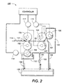
- the sheet conditioning device has transfer rollers 102 and 103 which are contacted by the lead edge of incoming sheets 52 as the sheets enter the nip area 101.
- Transfer rollers 102 and 103 are fixed as are metering rollers 104 and 105 that are in nip forming contact with transfer rollers 102 and 103, respectively.
- Back-up rollers 106 and 107 form a nip with transfer rollers 102 and 103, respectively, while paper is present.
- Metering roller 104 is positioned with a portion thereof situated within an open part of fluid pan 110.
- Metering roller 105 is positioned in contact with transfer roller 103 to form a fluid reservoir in the nip 111.
- End seals retain the fluid in said reservoir.
- Servo motors 114 and 115 are connected to transfer and metering rollers 104 and 102, and 103 and 105 respectively, and are adapted to drive the transfer rolls in the opposite direction to the paper travel through the paper path 116 and thereby controlling the amount of fluid applied to each surface.
- the wetting agent in this case water, is distributed to the metering rolls 104 and 105 from a pan and reservoir 110, 111, respectively, by way of sump 120, pump 125, and hoses 130. It should be understood that transfer rollers 102 and 103, as well as, metering rollers 104 and 105 could be made to articulate up and down to open and close nips with the back-up rollers 106 and 107, if desired.
- Some variables which affect how much moisture needs to be added for a sheet to rapidly reach equilibrium in an uncurled condition after fusing are: fuser and pressure roll temperature (affects moisture loss in the fuser); dwell time; initial sheet moisture content while in the feeder tray (will determine post fuser sheet moisture content); pre-fuser sheet temperature (will determine temperature rise and, therefore, moisture loss in the fuser); room relative humidity and temperature (determines equilibration relative humidity); wire or felt side being imaged (determines moisturization rate) ; sheet characteristics, such as, sheet basis weight, density, thickness, percent of moisture change as a function of fuser temperature, initial percent moisture, etc. (determines amount of moisture loss in the fuser).
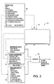
- Machine 8 in FIG. 3, in accordance with the present invention, is equipped with conventional temperature and humidity sensors to monitor machine characteristics as shown in block 94, environmental conditions as depicted in block 93, and a look-up table at block 95 that includes various paper characteristics.
- a user interface (UI) 91 allows an operator to inform the machine of the type of paper used as shown in block 92 which in turn sends a signal for incorporation into look-up table 95.
- Output signals from all three sources (93, 94 and 95) go to a controller 90 which uses appropriate conventional algorithms to adjust the amount of moisture added to each side of a sheet as it exits the fuser.
- controller 90 determines and adjusts the amount of water being transferred to each side of the sheet 52 by actuating servo motors 114 and 115 that are connected to transfer rolls 102 and 103 accordingly to either increase or decrease the speed of the transfer rollers in the opposite direction to the back-up rollers.
- the toner then solidifies onto the sheet, and the sheet soon reaches its equilibrates size.
- the moisturization process can leave the sheet with a slightly higher than equilibrated moisture content as it leaves the machine. Additional contraction of the toner as it cools to room temperature will be compensated for by some contraction of the sheet as the excess moisture is lost to the environment.
- Transfer roll speed V0 (a1 + a2 + a3 + a4 + a5 + a6.)
- V0 is a nominal speed equal to and in the opposite direction as the back-up roll speed
- a1 is a coefficient associated with paper stiffness
- a2 is a coefficient associated with basis weight
- a3 is associated with fuser temperature
- a4 is associated with wire or felt side
- a5 is associated with surface coating
- a6 is associated with image density, etc.
- the fuser roller or pressure roller temperature is high, more moisture needs to be added since more would be driven out in the fuser. If the paper stiffness is high, its beam strength will resist curling and less moisture needs to be added. If the image density is high, the imaged sheet will require more moisture to resist the effect of the increased toner mass.
Abstract
Description
- This invention relates generally to a substrate conditioning device for an electrophotographic printing machine and, more particularly, concerns a moisture control system that applies moisture to cut sheets in a full color process printing machine such that sheets reach equilibrium in a relatively uncurled or flat state.
- In a typical electrophotographic printing process, a photoconductive member is charged to a substantially uniform potential so as to sensitize the surface thereof. The charged portion of the photoconductive member is exposed to a light image of an original document being reproduced. Exposure of the charged photoconductive member selectively dissipates the charges thereon in the irradiated areas. This records an electrostatic latent image on the photoconductive member corresponding to the informational areas contained within the original document. After the electrostatic latent image is recorded on the photoconductive member, the latent image is developed by bringing a developer material into contact therewith. Generally, the developer material comprises toner particles adhering triboelectrically to carrier granules. The toner particles are attracted from the carrier granules to the latent image forming a toner powder image on the photoconductive member. The toner powder image is then transferred from the photoconductive member to a copy sheet. The toner particles are heated to permanently affix the powder image to the copy sheet.
- The foregoing generally describes a typical black and white electrophotographic printing machine. With the advent of multicolor electrophotography, it is desirable to use an architecture which comprises a plurality of image forming stations. One example of the plural image forming station architecture utilizes an image-on-image (IOI) system in which the photoreceptive member is recharged, reimaged and developed for each color separation. This charging, imaging, developing and recharging, reimaging and developing, all followed by transfer to paper, is done in a single revolution of the photoreceptor in so-called single pass machines, while multipass architectures form each color separation with a single charge, image and develop, with separate transfer operations for each color. The single pass architecture offers a potential for high throughput.
- In order to fix or fuse electroscopic toner material onto a support member by heat and pressure, it is necessary to apply pressure and elevate the temperature of the toner to a point at which the constituents of the toner material become tacky and coalesce. This action causes the toner to flow to some extent into the fibers or pores of the support medium (typically paper) . Thereafter, as the toner material cools, solidification of the toner material occurs, causing the toner material to be bonded firmly to the support member. In both the xerographic as well as the electrographic recording arts, the use of thermal energy and pressure for fixing toner images onto a support member is old and well known.
- One approach to heat and pressure fixing of electroscopic toner images onto a support has been to pass the support bearing the toner images between a pair of opposed roller members, at least one of which is internally heated. During operation of a fixing system of this type, the support member to which the toner images are electrostatically adhered is moved through the nip formed between the rolls and thereby heated under pressure. A large quantity of heat is applied to the toner and the copy sheet bearing the toner image. This heat evaporates much of the moisture contained in the sheet and heats the toner above the glass transition temperature. As the toner cools and hardens, it assumes the size of the paper which is now smaller than its final size due to the moisture loss. However, over the next 2 to 30 minutes, the paper absorbs moisture from the environment and expands. The toner does not expand and this creates stresses which results in curl.
- A number of solutions to this problem have been advanced. One solution advanced is to use an offset press dampening system to add moisture to each sheet as it exits the copier. These systems typically rely on the generation of a pool of water at a roll interface to distribute the water evenly along the rolls. Such systems usually operate with a web paper supply and their use with a cut sheet feeder system creates some difficulties not previously contemplated or addressed. Normal dampening systems are more appropriate for use with conventional offset presses.
- US-A-4,652,110 attempts to replenish moisture lost in the fixing process by collecting moisture as it is driven off the copy sheet for reapplication to the sheet at a later time.
- It is still desirable to control curl by moisturizing the paper immediately after fusing so that in the equilibrated state, the paper will be at or close to the size of the hardened toner.
- US-A-5,434,029 describes an apparatus and method of preventing the curling of a substrate having toner images electrostatically adhered thereto which substrate has been subjected to heat for the purpose of fixing the toner images to the substrate. Simultaneous constraint of the copy substrate and the application of moisture thereto is effected by passing the substrate through the nip formed by two pressure engaged rollers, one of which is utilized for applying the water to the back side of the substrate as the substrate passes through the aftermentioned nip.
- US-A-5,264,899 describes a system for adding moisture to a copy sheet. The toner fixation step of electrostatographic reproduction desiccates paper, which may lead to the formation a wave along the sheet edge. This discloses a pair of porous rolls defining a nip to transfer additional moisture to the copy sheet as it is passed through the nip. The added moisture prevents edge wave formation.
- In accordance with an embodiment of the present invention, there is provided a copier/printer, comprising: a pair of reservoirs with each of said pair of reservoirs storing a quantity of liquid; first and second generally cylindrical transfer rolls, each having an outer cylindrical surface which can be made to retain a thin film of fluid; first and second generally cylindrical back-up rollers, each having an outer cylindrical surface which can be rubber coated and suited to driving paper; said first and second transfer rolls and said first and second back-up rolls being aligned with respect to one another along their axis so as to define a small gap between said outer cylindrical surfaces; first and second metering rolls with each of said metering rolls in circumferential surface contact with one of said first and second cylindrical transfer rolls for metering a thin film of fluid to said outer surface of said first and second cylindrical transfer rolls; a paper path spanning the distance between said first transfer and back-up rolls and said second transfer and back-up rolls, said paper path supports and guides the sheet between said rolls; a pair of servo motors with one each of said servo motors being connected to one each of said transfer roller metering roller pair for driving said rolls; an additional servo motor being connected to both back-up rolls for driving said rolls; and a controller connected to said transfer roll servo motors for controlling said transfer roll servo motors in driving said transfer roll servo motors in the opposite direction to the paper path direction thereby controlling the amount of fluid applied to each side of said sheet.
- A particular embodiment of an apparatus in accordance with this invention will now be described with reference to the accompanying drawings; in which:-
- FIG. 1 is a schematic elevational view of a full color image-on-image single pass electrophotographic printing machine utilizing the device described herein;
- FIG. 2 is a detailed elevational side view of the paper conditioning device in accordance with the present invention; and,
- FIG. 3 is a block diagram of moisturization inputs/outputs for curl control in accordance with the present invention.
-
- This embodiment relates to an imaging system which is used to produce color output in a single revolution or pass of a photoreceptor belt but it is also useable with a multiple pass color process system, a single or multiple pass highlight color system and a black and white printing system.
- Turning now to FIG. 1, the printing machine 8 of the present invention uses a charge retentive surface in the form of an Active Matrix (AMAT)
photoreceptor belt 10 supported for movement in the direction indicated byarrow 12, for advancing sequentially through the various xerographic process stations. The belt is entrained about adrive roller 14,tension roller 16 and fixedroller 18 and theroller 14 is operatively connected to adrive motor 20 for effecting movement of the belt through the xerographic stations. - With continued reference to FIG. 1, a portion of
belt 10 passes through charging station A where a corona generating device, indicated generally by thereference numeral 22, charges the photoconductive surface ofbelt 10 to a relatively high, substantially uniform, preferably negative potential. - Next, the charged portion of photoconductive surface is advanced through an imaging/exposure station B. At imaging/exposure station B, a controller, indicated generally by
reference numeral 90, receives the image signals representing the desired output image and processes these signals to convert them to the various color separations of the image which is transmitted to a laser basedoutput scanning device 24 which causes the charge retentive surface to be discharged in accordance with the output from the scanning device. Preferably the scanning device is a laser Raster Output Scanner (ROS). Alternatively, the ROS could be replaced by other xerographic exposure devices such as LED arrays. - The photoreceptor, which is initially charged to a voltage V0, undergoes dark decay to a level Vddp equal to about -500 volts. When exposed at the exposure station B it is discharged to Vexpose equal to about -50 volts. Thus after exposure, the photoreceptor contains a monopolar voltage profile of high and low voltages, the former corresponding to charged areas and the latter corresponding to discharged or background areas.
- At a first development station C with
black toner 35, developer structure, indicated generally by thereference numeral 42 utilizing a hybrid jumping development (HJD) system, the development roll, better known as the donor roll, is powered by two development fields (potentials across an air gap). The first field is the ac jumping field which is used for toner cloud generation. The second field is the dc development field which is used to control the amount of developed toner mass on the photoreceptor. The toner cloud causes charged toner particles to be attracted to the electrostatic latent image. Appropriate developer biasing is accomplished via a power supply. This type of system is a non-contact type in which only toner particles (black, for example) are attracted to the latent image and there is no mechanical contact between the photoreceptor and a toner delivery device to disturb a previously developed, but unfixed, image. - A
corona recharge device 36 having a high output current vs. control surface voltage (I/V) characteristic slope is employed for raising the voltage level of both the toned and untoned areas on the photoreceptor to a substantially uniform level. Therecharging device 36 serves to recharge the photoreceptor to a predetermined level. - A second exposure/
imaging device 38 which comprises a laser based output structure is utilized for selectively discharging the photoreceptor on toned areas and/or bare areas, pursuant to the image to be developed with the second color toner. At this point, the photoreceptor contains toned and untoned areas at relatively high voltage levels and toned and untoned areas at relatively low voltage levels. These low voltage areas represent image areas which are developed using discharged area development (DAD). To this end, a negatively charged,developer material 40 comprising color toner is employed. The toner, which by way of example may be yellow, is contained in adeveloper housing structure 42 disposed at a second developer station D and is presented to the latent images on the photoreceptor by way of a second HSD developer system. A power supply (not shown) serves to electrically bias the developer structure to a level effective to develop the discharged image areas with negatively chargedyellow toner particles 40. - The above procedure is repeated for a third imager for a third suitable color toner such as magenta and for a fourth imager and suitable color toner such as cyan. The exposure control scheme described below may be utilized for these subsequent imaging steps. In this manner a full color composite toner image is developed on the photoreceptor belt.
- To the extent to which some toner charge is totally neutralized, or the polarity reversed, thereby causing the composite image developed on the photoreceptor to consist of both positive and negative toner, a negative
pre-transfer dicorotron member 50 is provided to condition the toner for effective transfer to a substrate using positive corona discharge. - Subsequent to image development a sheet of
support material 52 is moved eithertray belt 10 in a timed sequence so that the toner powder image developed thereon contacts the advancing sheet of support material at transfer station G. - Transfer station G includes a
transfer dicorotron 54 which sprays positive ions onto the backside ofsheet 52. This attracts the negatively charged toner powder images from thebelt 10 tosheet 52. Adetack dicorotron 56 is provided for facilitating stripping of the sheets from thebelt 10. - After transfer, the sheet continues to move, in the direction of
arrow 58, onto a conveyor (not shown) which advances the sheet to fusing station H. Fusing station H includes a fuser assembly, indicated generally by thereference numeral 60, which permanently affixes the transferred powder image tosheet 52. Preferably,fuser assembly 60 comprises aheated fuser roller 62 and a backup orpressure roller 64.Sheet 52 passes betweenfuser roller 62 andbackup roller 64 with the toner powder image contactingfuser roller 62. In this manner, the toner powder images are permanently affixed tosheet 52. After fusing, a chute, not shown, guides the advancingsheets 52 to a catch tray, not shown, for subsequent removal from the printing machine by the operator. - After the sheet of support material is separated from photoconductive surface of
belt 10, the residual toner particles carried by the non-image areas on the photoconductive surface are removed therefrom. These particles are removed at cleaning station I using a cleaning brush structure contained in ahousing 66. - It is believed that the foregoing description is sufficient for the purposes of the present application to illustrate the general operation of a color printing machine.
- As shown in FIG. 2, the sheet conditioning device, generally referred to as
reference numeral 100, hastransfer rollers incoming sheets 52 as the sheets enter thenip area 101.Transfer rollers metering rollers transfer rollers rollers transfer rollers Metering roller 104 is positioned with a portion thereof situated within an open part offluid pan 110.Metering roller 105 is positioned in contact withtransfer roller 103 to form a fluid reservoir in the nip 111. End seals (not shown) retain the fluid in said reservoir.Servo motors metering rollers paper path 116 and thereby controlling the amount of fluid applied to each surface. The wetting agent, in this case water, is distributed to the metering rolls 104 and 105 from a pan andreservoir 110, 111, respectively, by way ofsump 120, pump 125, andhoses 130. It should be understood thattransfer rollers metering rollers rollers - There are many parameters which contribute to curl, some of which are fixed by the machine fuser configuration, xerographics, or are outside the control of the machine, such as, image location and image density. Some variables which affect how much moisture needs to be added for a sheet to rapidly reach equilibrium in an uncurled condition after fusing are: fuser and pressure roll temperature (affects moisture loss in the fuser); dwell time; initial sheet moisture content while in the feeder tray (will determine post fuser sheet moisture content); pre-fuser sheet temperature (will determine temperature rise and, therefore, moisture loss in the fuser); room relative humidity and temperature (determines equilibration relative humidity); wire or felt side being imaged (determines moisturization rate) ; sheet characteristics, such as, sheet basis weight, density, thickness, percent of moisture change as a function of fuser temperature, initial percent moisture, etc. (determines amount of moisture loss in the fuser).
- Machine 8 in FIG. 3, in accordance with the present invention, is equipped with conventional temperature and humidity sensors to monitor machine characteristics as shown in
block 94, environmental conditions as depicted inblock 93, and a look-up table atblock 95 that includes various paper characteristics. A user interface (UI) 91 allows an operator to inform the machine of the type of paper used as shown inblock 92 which in turn sends a signal for incorporation into look-up table 95. Output signals from all three sources (93, 94 and 95) go to acontroller 90 which uses appropriate conventional algorithms to adjust the amount of moisture added to each side of a sheet as it exits the fuser. - In use, an operator will designate which sheet is loaded in which supply tray via a selection on
UI 91. The operator then indicates on the UI whether the sheets are loaded wire side or felt side up. This information is used in look-up table 95 which contains information about now the moisture content of that particular sheet changes as a function of fuser temperature, initial sheet temperature, initial moisture content, moisturization fluid characteristics, etc. This information could be determined experimentally. Given all these variables,controller 90 determines and adjusts the amount of water being transferred to each side of thesheet 52 by actuatingservo motors rolls - An algorithm for controlling the speed of the stepper motors which determine the amount of water applied to each side of the sheet:
Transfer roll speed = V0 (a1 + a2 + a3 + a4 + a5 + a6.....) - Where V0 is a nominal speed equal to and in the opposite direction as the back-up roll speed, and a1is a coefficient associated with paper stiffness, a2 is a coefficient associated with basis weight, a3 is associated with fuser temperature, a4 is associated with wire or felt side, a5 is associated with surface coating, a6 is associated with image density, etc.
- For example, if the fuser roller or pressure roller temperature is high, more moisture needs to be added since more would be driven out in the fuser. If the paper stiffness is high, its beam strength will resist curling and less moisture needs to be added. If the image density is high, the imaged sheet will require more moisture to resist the effect of the increased toner mass.
- In recapitulation, there is provided a scheme for determining the critical machine and environmental characteristics through a series of on-line sensors, and to use an operator selectable table to indicate the type of paper loaded in each paper tray. Software then uses this information to determine how much moisture should be added to each side of a sheet of paper in order for it to reach a flat state when it reaches equilibrium moisture content. For example, different amounts of moisture can be added to each and every sheet in a precollated print job by using the heretofore mentioned algorithm. The transfer roll speed would change between sheets entering the nip formed between the transfer roll and back-up roll. Hardware is included that upon actuation by the software places the desired predetermined film thickness on each sheet surface.
Claims (7)
- A system that adds moisture to copy sheets while en route in a copier/printer to control curl, comprising:a pair of back-up rolls (106,107) and a pair of generally cylindrical transfer rolls (102,103), each having an outer cylindrical surface, said transfer rolls and said back-up rolls defining nips between their outer cylindrical surfaces;a pair of metering rolls (104,105) with one each of said pair of metering rolls in circumferential surface contact with one each of said cylindrical transfer rolls (102,103) for wetting said outer surfaces of said cylindrical transfer rolls (102,103);a pair of servo motors (115) with one each of said servo motors being connected to one each of said transfer rolls (102,103); and,a controller (100) connected to said servo motors (115) for controlling said servo motors (115) in driving said pair of transfer rolls (102,103) in a direction opposite to the direction of conveyance of the sheets and thereby controlling the amount of fluid applied to each side of the sheets .
- A system according to claim 1, also comprisinga pair of reservoirs (110,120) with each of said pair of reservoirs storing a quantity of liquid.
- A system for fixing a toner image to a copy sheet in an electrophotographic system so as to avoid the formation of a curl in the body of the sheet, comprising: first and second fusing rollers (62,64) defining a nip therebetween, at least one of said fusing rollers (62,64) being heated, wherein the fusing rollers serve to fix a toner image on a copy sheet through the application of heat and pressure to the copy sheet; anda sheet conditioning system according to claim 1 or 2.
- A system according to claim 3, including a tray for holding the copy sheets, and sensors for sensing relative humidity of said tray, room temperature and room relative humidity and transmitting signals indicative of the same to said controller (100).
- A system according to claim 3 or 4, including inputs to said controller (100) characterizing fuser roll temperature, dwell time, pressure roll temperature and moisturization fluid characteristics.
- A system according to claim 3, 4 or 5, including a lookup table that provides input to said controller (100) of sheet characteristics encompassing sheet basis weight, sheet density, surface coating, thickness and percent of moisture change as a function of fuser temperature, and initial percent of moisture.
- A system according to claim 3, 4, 5 or 6, wherein said controller (100) either increases or decreases servo motor (115) speed based on environmemtal inputs, machine characteristics, paper characteristics, and image type.
Applications Claiming Priority (2)
| Application Number | Priority Date | Filing Date | Title |
|---|---|---|---|
| US08/940,110 US5842105A (en) | 1997-09-29 | 1997-09-29 | Controlled moisturization of paper to eliminate curl |
| US940110 | 1997-09-29 |
Publications (3)
| Publication Number | Publication Date |
|---|---|
| EP0905574A2 true EP0905574A2 (en) | 1999-03-31 |
| EP0905574A3 EP0905574A3 (en) | 2000-05-24 |
| EP0905574B1 EP0905574B1 (en) | 2003-07-09 |
Family
ID=25474248
Family Applications (1)
| Application Number | Title | Priority Date | Filing Date |
|---|---|---|---|
| EP98307479A Expired - Lifetime EP0905574B1 (en) | 1997-09-29 | 1998-09-15 | Controlled moisturization of paper to eliminate curl |
Country Status (4)
| Country | Link |
|---|---|
| US (1) | US5842105A (en) |
| EP (1) | EP0905574B1 (en) |
| JP (1) | JP4558853B2 (en) |
| DE (1) | DE69816212T2 (en) |
Cited By (2)
| Publication number | Priority date | Publication date | Assignee | Title |
|---|---|---|---|---|
| DE10040368A1 (en) * | 2000-08-18 | 2002-03-07 | Nexpress Solutions Llc | Setting of unit to create images in multi color printing machine using detected paper fibre orientation and stored paper characteristics |
| US6767431B2 (en) * | 1999-03-23 | 2004-07-27 | Metso Paper, Inc. | Method for measuring and regulating curl in a paper or board web and a paper or board machine line |
Families Citing this family (20)
| Publication number | Priority date | Publication date | Assignee | Title |
|---|---|---|---|---|
| US6011947A (en) * | 1997-09-29 | 2000-01-04 | Xerox Corporation | Apparatus and method for automatically adjusting water film thickness on conditioner metering rolls |
| US5987301A (en) * | 1997-09-29 | 1999-11-16 | Xerox Corporation | Paper conditioning system |
| JPH11216881A (en) * | 1997-10-30 | 1999-08-10 | Xerox Corp | Method for generating printer driver and color print system using the printer driver |
| US5930578A (en) * | 1998-04-30 | 1999-07-27 | Xerox Corporation | Moisturizing rolls with end grooves for eliminating water spill from their ends |
| US6052553A (en) * | 1999-05-27 | 2000-04-18 | Xerox Corporation | Post-fusing sheet conditioning apparatus |
| US6249667B1 (en) * | 2000-03-03 | 2001-06-19 | Xerox Corporation | Conditioner rolls end seals |
| JP4533230B2 (en) * | 2005-04-28 | 2010-09-01 | キヤノン株式会社 | Image forming apparatus |
| US8107099B2 (en) * | 2005-06-24 | 2012-01-31 | Xerox Corporation | Watermarking |
| TWI274970B (en) * | 2005-08-22 | 2007-03-01 | Benq Corp | Laser printer and perfume diffusing structure thereof |
| JP4702170B2 (en) * | 2006-05-10 | 2011-06-15 | 富士ゼロックス株式会社 | Image forming apparatus and sheet correction apparatus used therefor |
| JP2008044765A (en) * | 2006-08-21 | 2008-02-28 | Konica Minolta Business Technologies Inc | Device for supplying water to sheet and image forming device |
| US8038280B2 (en) * | 2008-04-09 | 2011-10-18 | Xerox Corporation | Ink-jet printer and method for decurling cut sheet media prior to ink-jet printing |
| JP5517788B2 (en) | 2010-07-01 | 2014-06-11 | キヤノン株式会社 | Image forming apparatus |
| JP5583513B2 (en) * | 2010-08-10 | 2014-09-03 | 富士フイルム株式会社 | Seasoning device, image forming device |
| JP2015515427A (en) * | 2012-04-27 | 2015-05-28 | オセ−テクノロジーズ ビーブイ | Print media moisturizing unit |
| JP6165190B2 (en) * | 2014-04-30 | 2017-07-19 | キヤノン株式会社 | Sheet conveying apparatus and image forming apparatus |
| JP2016184094A (en) * | 2015-03-26 | 2016-10-20 | コニカミノルタ株式会社 | Sheet processing apparatus and image forming system |
| JP6344280B2 (en) * | 2015-03-26 | 2018-06-20 | コニカミノルタ株式会社 | Recording medium processing apparatus, image forming apparatus, and image forming system |
| JP6149889B2 (en) * | 2015-04-09 | 2017-06-21 | コニカミノルタ株式会社 | Paper humidification device and paper humidification method |
| US11584121B2 (en) | 2018-08-14 | 2023-02-21 | Hewlett-Packard Development Company, L.P. | Inhibiting media deformation |
Citations (4)
| Publication number | Priority date | Publication date | Assignee | Title |
|---|---|---|---|---|
| US3647525A (en) * | 1959-10-05 | 1972-03-07 | Dahlgren Mfg Co | Method and means for applying liquid to a moving web |
| US5264899A (en) * | 1992-10-21 | 1993-11-23 | Xerox Corporation | Sheet moisture replacement system using porous rolls |
| US5434029A (en) * | 1991-05-06 | 1995-07-18 | Xerox Corporation | Curl prevention method for high TMA color copiers |
| EP0862091A2 (en) * | 1997-02-28 | 1998-09-02 | Xerox Corporation | Device and system for conditioning a copy sheet |
Family Cites Families (7)
| Publication number | Priority date | Publication date | Assignee | Title |
|---|---|---|---|---|
| JPS59223644A (en) * | 1983-05-23 | 1984-12-15 | Fuji Xerox Co Ltd | Curl correcting apparatus in machine-glazed paper feeding apparatus |
| JPS61116658U (en) * | 1984-12-29 | 1986-07-23 | ||
| JPH0743726Y2 (en) * | 1989-05-24 | 1995-10-09 | 株式会社リコー | Wet developing device |
| JPH03127362U (en) * | 1990-04-04 | 1991-12-20 | ||
| JPH0458548U (en) * | 1990-09-27 | 1992-05-20 | ||
| JPH08297417A (en) * | 1995-04-27 | 1996-11-12 | Minolta Co Ltd | Liquid developer carrying device |
| JPH09329972A (en) * | 1996-06-12 | 1997-12-22 | Ricoh Co Ltd | Wet-type image forming device |
-
1997
- 1997-09-29 US US08/940,110 patent/US5842105A/en not_active Expired - Lifetime
-
1998
- 1998-09-15 DE DE69816212T patent/DE69816212T2/en not_active Expired - Lifetime
- 1998-09-15 EP EP98307479A patent/EP0905574B1/en not_active Expired - Lifetime
- 1998-09-21 JP JP26641898A patent/JP4558853B2/en not_active Expired - Fee Related
Patent Citations (4)
| Publication number | Priority date | Publication date | Assignee | Title |
|---|---|---|---|---|
| US3647525A (en) * | 1959-10-05 | 1972-03-07 | Dahlgren Mfg Co | Method and means for applying liquid to a moving web |
| US5434029A (en) * | 1991-05-06 | 1995-07-18 | Xerox Corporation | Curl prevention method for high TMA color copiers |
| US5264899A (en) * | 1992-10-21 | 1993-11-23 | Xerox Corporation | Sheet moisture replacement system using porous rolls |
| EP0862091A2 (en) * | 1997-02-28 | 1998-09-02 | Xerox Corporation | Device and system for conditioning a copy sheet |
Cited By (4)
| Publication number | Priority date | Publication date | Assignee | Title |
|---|---|---|---|---|
| US6767431B2 (en) * | 1999-03-23 | 2004-07-27 | Metso Paper, Inc. | Method for measuring and regulating curl in a paper or board web and a paper or board machine line |
| DE10040368A1 (en) * | 2000-08-18 | 2002-03-07 | Nexpress Solutions Llc | Setting of unit to create images in multi color printing machine using detected paper fibre orientation and stored paper characteristics |
| DE10040368C2 (en) * | 2000-08-18 | 2002-12-12 | Nexpress Solutions Llc | Method and device for setting devices for generating partial color images in a multicolor printing machine |
| US6587652B2 (en) | 2000-08-18 | 2003-07-01 | Nexpress Solutions Llc | Adjusting devices and method taking substrate changes into account for generating color separations in a multicolor printing machine |
Also Published As
| Publication number | Publication date |
|---|---|
| EP0905574A3 (en) | 2000-05-24 |
| DE69816212T2 (en) | 2004-02-12 |
| EP0905574B1 (en) | 2003-07-09 |
| DE69816212D1 (en) | 2003-08-14 |
| JPH11161108A (en) | 1999-06-18 |
| JP4558853B2 (en) | 2010-10-06 |
| US5842105A (en) | 1998-11-24 |
Similar Documents
| Publication | Publication Date | Title |
|---|---|---|
| EP0905574B1 (en) | Controlled moisturization of paper to eliminate curl | |
| US5850589A (en) | Sheet moisture replacement system using water jet technology | |
| EP0905573B1 (en) | Paper conditioning apparatus | |
| US5970300A (en) | Apparatus for applying scents to paper in a printer/copier | |
| US6011947A (en) | Apparatus and method for automatically adjusting water film thickness on conditioner metering rolls | |
| US6052553A (en) | Post-fusing sheet conditioning apparatus | |
| US5937258A (en) | Paper conditioner with articulating back-up/transfer rollers | |
| EP1293845B1 (en) | Composite blade for assisting complete transfer of a toner image from a photosensitive surface | |
| EP1288736A2 (en) | Multi-function air knife | |
| US8027603B2 (en) | Fuser apparatus having fuser cleaner web and corresponding methods | |
| US5920751A (en) | Apparatus and method for controlling moisture and cooling rate for paper curl reduction | |
| US5895154A (en) | Textured rollers for paper conditioning | |
| US8064813B2 (en) | Fuser apparatus having fuser cleaner web and corresponding methods | |
| US6564020B2 (en) | Image forming apparatus | |
| US5930578A (en) | Moisturizing rolls with end grooves for eliminating water spill from their ends | |
| US6249667B1 (en) | Conditioner rolls end seals | |
| US5832359A (en) | Apparatus and method for sensing water film thickness on conditioner rolls | |
| US7796907B2 (en) | Method and apparatus for detecting and avoiding a defect on a fuser web | |
| US6438333B1 (en) | Image forming apparatus with reduced transfer current to transfer material rear end | |
| JPH05333722A (en) | Image forming device | |
| US6453142B1 (en) | Developing apparatus equipped with developing roller having a dielectric layer outer surface | |
| JP2001312160A (en) | Image forming device | |
| JPH0980937A (en) | Transfer device for image forming device | |
| JP2001188420A (en) | Image forming device | |
| MXPA98000678A (en) | Paper conditioner with transfer rollers / articulan backrest |
Legal Events
| Date | Code | Title | Description |
|---|---|---|---|
| PUAI | Public reference made under article 153(3) epc to a published international application that has entered the european phase |
Free format text: ORIGINAL CODE: 0009012 |
|
| AK | Designated contracting states |
Kind code of ref document: A2 Designated state(s): DE FR GB |
|
| AX | Request for extension of the european patent |
Free format text: AL;LT;LV;MK;RO;SI |
|
| PUAL | Search report despatched |
Free format text: ORIGINAL CODE: 0009013 |
|
| AK | Designated contracting states |
Kind code of ref document: A3 Designated state(s): AT BE CH CY DE DK ES FI FR GB GR IE IT LI LU MC NL PT SE |
|
| AX | Request for extension of the european patent |
Free format text: AL;LT;LV;MK;RO;SI |
|
| RIC1 | Information provided on ipc code assigned before grant |
Free format text: 7G 03G 15/00 A, 7B 05C 1/08 B, 7B 05C 11/02 B |
|
| 17P | Request for examination filed |
Effective date: 20001124 |
|
| AKX | Designation fees paid |
Free format text: DE FR GB |
|
| 17Q | First examination report despatched |
Effective date: 20020527 |
|
| GRAH | Despatch of communication of intention to grant a patent |
Free format text: ORIGINAL CODE: EPIDOS IGRA |
|
| GRAH | Despatch of communication of intention to grant a patent |
Free format text: ORIGINAL CODE: EPIDOS IGRA |
|
| GRAA | (expected) grant |
Free format text: ORIGINAL CODE: 0009210 |
|
| AK | Designated contracting states |
Designated state(s): DE FR GB |
|
| REG | Reference to a national code |
Ref country code: GB Ref legal event code: FG4D |
|
| REF | Corresponds to: |
Ref document number: 69816212 Country of ref document: DE Date of ref document: 20030814 Kind code of ref document: P |
|
| ET | Fr: translation filed | ||
| PLBE | No opposition filed within time limit |
Free format text: ORIGINAL CODE: 0009261 |
|
| STAA | Information on the status of an ep patent application or granted ep patent |
Free format text: STATUS: NO OPPOSITION FILED WITHIN TIME LIMIT |
|
| 26N | No opposition filed |
Effective date: 20040414 |
|
| REG | Reference to a national code |
Ref country code: GB Ref legal event code: 746 Effective date: 20050512 |
|
| REG | Reference to a national code |
Ref country code: FR Ref legal event code: PLFP Year of fee payment: 18 |
|
| PGFP | Annual fee paid to national office [announced via postgrant information from national office to epo] |
Ref country code: GB Payment date: 20150825 Year of fee payment: 18 Ref country code: DE Payment date: 20150820 Year of fee payment: 18 |
|
| PGFP | Annual fee paid to national office [announced via postgrant information from national office to epo] |
Ref country code: FR Payment date: 20150824 Year of fee payment: 18 |
|
| REG | Reference to a national code |
Ref country code: DE Ref legal event code: R119 Ref document number: 69816212 Country of ref document: DE |
|
| GBPC | Gb: european patent ceased through non-payment of renewal fee |
Effective date: 20160915 |
|
| REG | Reference to a national code |
Ref country code: FR Ref legal event code: ST Effective date: 20170531 |
|
| PG25 | Lapsed in a contracting state [announced via postgrant information from national office to epo] |
Ref country code: DE Free format text: LAPSE BECAUSE OF NON-PAYMENT OF DUE FEES Effective date: 20170401 Ref country code: FR Free format text: LAPSE BECAUSE OF NON-PAYMENT OF DUE FEES Effective date: 20160930 Ref country code: GB Free format text: LAPSE BECAUSE OF NON-PAYMENT OF DUE FEES Effective date: 20160915 |