EP0906890B1 - Vorrichtung zur Wasserstofferzeugung,Vorrichtung zur Kohlenmonoxid-Verringerung,Vorrichtung zur Kohlenmonoxid-Oxidation,Vorrichtung zum katalytischen Verbrennen und Verfahren zur Herstellung eines Katalysators - Google Patents
Vorrichtung zur Wasserstofferzeugung,Vorrichtung zur Kohlenmonoxid-Verringerung,Vorrichtung zur Kohlenmonoxid-Oxidation,Vorrichtung zum katalytischen Verbrennen und Verfahren zur Herstellung eines Katalysators Download PDFInfo
- Publication number
- EP0906890B1 EP0906890B1 EP98118264A EP98118264A EP0906890B1 EP 0906890 B1 EP0906890 B1 EP 0906890B1 EP 98118264 A EP98118264 A EP 98118264A EP 98118264 A EP98118264 A EP 98118264A EP 0906890 B1 EP0906890 B1 EP 0906890B1
- Authority
- EP
- European Patent Office
- Prior art keywords
- catalytic
- reaction mixture
- converter
- catalyst
- layer
- Prior art date
- Legal status (The legal status is an assumption and is not a legal conclusion. Google has not performed a legal analysis and makes no representation as to the accuracy of the status listed.)
- Expired - Lifetime
Links
- 239000001257 hydrogen Substances 0.000 title claims description 22
- 229910052739 hydrogen Inorganic materials 0.000 title claims description 22
- 230000003197 catalytic effect Effects 0.000 title claims description 19
- 238000000034 method Methods 0.000 title claims description 16
- UGFAIRIUMAVXCW-UHFFFAOYSA-N Carbon monoxide Chemical compound [O+]#[C-] UGFAIRIUMAVXCW-UHFFFAOYSA-N 0.000 title claims description 14
- 229910002091 carbon monoxide Inorganic materials 0.000 title claims description 14
- 238000004519 manufacturing process Methods 0.000 title claims description 14
- 230000003647 oxidation Effects 0.000 title claims description 7
- 238000007254 oxidation reaction Methods 0.000 title claims description 7
- 239000003054 catalyst Substances 0.000 title description 96
- 125000004435 hydrogen atom Chemical class [H]* 0.000 title 1
- OKKJLVBELUTLKV-UHFFFAOYSA-N Methanol Chemical compound OC OKKJLVBELUTLKV-UHFFFAOYSA-N 0.000 claims description 42
- 239000011541 reaction mixture Substances 0.000 claims description 41
- 239000000463 material Substances 0.000 claims description 24
- UFHFLCQGNIYNRP-UHFFFAOYSA-N Hydrogen Chemical compound [H][H] UFHFLCQGNIYNRP-UHFFFAOYSA-N 0.000 claims description 18
- 239000000843 powder Substances 0.000 claims description 16
- 238000003825 pressing Methods 0.000 claims description 15
- RYGMFSIKBFXOCR-UHFFFAOYSA-N Copper Chemical compound [Cu] RYGMFSIKBFXOCR-UHFFFAOYSA-N 0.000 claims description 14
- 239000007789 gas Substances 0.000 claims description 13
- 239000000376 reactant Substances 0.000 claims description 13
- 239000000047 product Substances 0.000 claims description 12
- 229910052802 copper Inorganic materials 0.000 claims description 10
- 239000010949 copper Substances 0.000 claims description 10
- 229910052751 metal Inorganic materials 0.000 claims description 9
- 239000002184 metal Substances 0.000 claims description 9
- QVGXLLKOCUKJST-UHFFFAOYSA-N atomic oxygen Chemical compound [O] QVGXLLKOCUKJST-UHFFFAOYSA-N 0.000 claims description 8
- 229910052760 oxygen Inorganic materials 0.000 claims description 8
- 239000001301 oxygen Substances 0.000 claims description 8
- 238000005245 sintering Methods 0.000 claims description 7
- 239000007795 chemical reaction product Substances 0.000 claims description 6
- BASFCYQUMIYNBI-UHFFFAOYSA-N platinum Chemical compound [Pt] BASFCYQUMIYNBI-UHFFFAOYSA-N 0.000 claims description 6
- XLYOFNOQVPJJNP-UHFFFAOYSA-N water Substances O XLYOFNOQVPJJNP-UHFFFAOYSA-N 0.000 claims description 6
- 238000006555 catalytic reaction Methods 0.000 claims description 5
- 238000007084 catalytic combustion reaction Methods 0.000 claims description 3
- 150000002431 hydrogen Chemical class 0.000 claims description 3
- 229910052697 platinum Inorganic materials 0.000 claims description 3
- 238000002485 combustion reaction Methods 0.000 claims description 2
- 229910000510 noble metal Inorganic materials 0.000 claims description 2
- 238000000197 pyrolysis Methods 0.000 claims description 2
- 238000000465 moulding Methods 0.000 claims 3
- 239000000446 fuel Substances 0.000 claims 1
- 238000009834 vaporization Methods 0.000 claims 1
- 230000008016 vaporization Effects 0.000 claims 1
- 238000006243 chemical reaction Methods 0.000 description 18
- 238000009826 distribution Methods 0.000 description 11
- 239000011159 matrix material Substances 0.000 description 4
- 239000000203 mixture Substances 0.000 description 4
- 229930195733 hydrocarbon Natural products 0.000 description 3
- 150000002430 hydrocarbons Chemical class 0.000 description 3
- 239000000126 substance Substances 0.000 description 3
- CURLTUGMZLYLDI-UHFFFAOYSA-N Carbon dioxide Chemical compound O=C=O CURLTUGMZLYLDI-UHFFFAOYSA-N 0.000 description 2
- LFQSCWFLJHTTHZ-UHFFFAOYSA-N Ethanol Chemical compound CCO LFQSCWFLJHTTHZ-UHFFFAOYSA-N 0.000 description 2
- 230000006835 compression Effects 0.000 description 2
- 238000007906 compression Methods 0.000 description 2
- 239000008187 granular material Substances 0.000 description 2
- 238000002156 mixing Methods 0.000 description 2
- 239000011148 porous material Substances 0.000 description 2
- 239000010970 precious metal Substances 0.000 description 2
- 238000002360 preparation method Methods 0.000 description 2
- 238000002407 reforming Methods 0.000 description 2
- 239000007858 starting material Substances 0.000 description 2
- OKTJSMMVPCPJKN-UHFFFAOYSA-N Carbon Chemical compound [C] OKTJSMMVPCPJKN-UHFFFAOYSA-N 0.000 description 1
- 239000004215 Carbon black (E152) Substances 0.000 description 1
- 239000011230 binding agent Substances 0.000 description 1
- 229910052799 carbon Inorganic materials 0.000 description 1
- 229910002092 carbon dioxide Inorganic materials 0.000 description 1
- 239000001569 carbon dioxide Substances 0.000 description 1
- 239000011248 coating agent Substances 0.000 description 1
- 238000000576 coating method Methods 0.000 description 1
- 238000010276 construction Methods 0.000 description 1
- 208000012839 conversion disease Diseases 0.000 description 1
- 230000007423 decrease Effects 0.000 description 1
- 230000003247 decreasing effect Effects 0.000 description 1
- 238000009792 diffusion process Methods 0.000 description 1
- 238000007599 discharging Methods 0.000 description 1
- 238000004090 dissolution Methods 0.000 description 1
- 230000000694 effects Effects 0.000 description 1
- 238000001704 evaporation Methods 0.000 description 1
- 230000008020 evaporation Effects 0.000 description 1
- 238000004880 explosion Methods 0.000 description 1
- 239000006260 foam Substances 0.000 description 1
- 230000000977 initiatory effect Effects 0.000 description 1
- 239000007769 metal material Substances 0.000 description 1
- 239000006262 metallic foam Substances 0.000 description 1
- 238000003541 multi-stage reaction Methods 0.000 description 1
- 239000002245 particle Substances 0.000 description 1
- 238000011084 recovery Methods 0.000 description 1
- 239000007787 solid Substances 0.000 description 1
- 230000002269 spontaneous effect Effects 0.000 description 1
- 230000000087 stabilizing effect Effects 0.000 description 1
Images
Classifications
-
- F—MECHANICAL ENGINEERING; LIGHTING; HEATING; WEAPONS; BLASTING
- F23—COMBUSTION APPARATUS; COMBUSTION PROCESSES
- F23C—METHODS OR APPARATUS FOR COMBUSTION USING FLUID FUEL OR SOLID FUEL SUSPENDED IN A CARRIER GAS OR AIR
- F23C13/00—Apparatus in which combustion takes place in the presence of catalytic material
- F23C13/08—Apparatus in which combustion takes place in the presence of catalytic material characterised by the catalytic material
-
- B—PERFORMING OPERATIONS; TRANSPORTING
- B01—PHYSICAL OR CHEMICAL PROCESSES OR APPARATUS IN GENERAL
- B01B—BOILING; BOILING APPARATUS ; EVAPORATION; EVAPORATION APPARATUS
- B01B1/00—Boiling; Boiling apparatus for physical or chemical purposes ; Evaporation in general
- B01B1/005—Evaporation for physical or chemical purposes; Evaporation apparatus therefor, e.g. evaporation of liquids for gas phase reactions
-
- B—PERFORMING OPERATIONS; TRANSPORTING
- B01—PHYSICAL OR CHEMICAL PROCESSES OR APPARATUS IN GENERAL
- B01J—CHEMICAL OR PHYSICAL PROCESSES, e.g. CATALYSIS OR COLLOID CHEMISTRY; THEIR RELEVANT APPARATUS
- B01J12/00—Chemical processes in general for reacting gaseous media with gaseous media; Apparatus specially adapted therefor
- B01J12/007—Chemical processes in general for reacting gaseous media with gaseous media; Apparatus specially adapted therefor in the presence of catalytically active bodies, e.g. porous plates
-
- B—PERFORMING OPERATIONS; TRANSPORTING
- B01—PHYSICAL OR CHEMICAL PROCESSES OR APPARATUS IN GENERAL
- B01J—CHEMICAL OR PHYSICAL PROCESSES, e.g. CATALYSIS OR COLLOID CHEMISTRY; THEIR RELEVANT APPARATUS
- B01J15/00—Chemical processes in general for reacting gaseous media with non-particulate solids, e.g. sheet material; Apparatus specially adapted therefor
- B01J15/005—Chemical processes in general for reacting gaseous media with non-particulate solids, e.g. sheet material; Apparatus specially adapted therefor in the presence of catalytically active bodies, e.g. porous plates
-
- B—PERFORMING OPERATIONS; TRANSPORTING
- B01—PHYSICAL OR CHEMICAL PROCESSES OR APPARATUS IN GENERAL
- B01J—CHEMICAL OR PHYSICAL PROCESSES, e.g. CATALYSIS OR COLLOID CHEMISTRY; THEIR RELEVANT APPARATUS
- B01J19/00—Chemical, physical or physico-chemical processes in general; Their relevant apparatus
- B01J19/24—Stationary reactors without moving elements inside
- B01J19/248—Reactors comprising multiple separated flow channels
- B01J19/249—Plate-type reactors
-
- B—PERFORMING OPERATIONS; TRANSPORTING
- B01—PHYSICAL OR CHEMICAL PROCESSES OR APPARATUS IN GENERAL
- B01J—CHEMICAL OR PHYSICAL PROCESSES, e.g. CATALYSIS OR COLLOID CHEMISTRY; THEIR RELEVANT APPARATUS
- B01J35/00—Catalysts, in general, characterised by their form or physical properties
-
- B01J35/30—
-
- C—CHEMISTRY; METALLURGY
- C01—INORGANIC CHEMISTRY
- C01B—NON-METALLIC ELEMENTS; COMPOUNDS THEREOF; METALLOIDS OR COMPOUNDS THEREOF NOT COVERED BY SUBCLASS C01C
- C01B3/00—Hydrogen; Gaseous mixtures containing hydrogen; Separation of hydrogen from mixtures containing it; Purification of hydrogen
- C01B3/02—Production of hydrogen or of gaseous mixtures containing a substantial proportion of hydrogen
- C01B3/06—Production of hydrogen or of gaseous mixtures containing a substantial proportion of hydrogen by reaction of inorganic compounds containing electro-positively bound hydrogen, e.g. water, acids, bases, ammonia, with inorganic reducing agents
- C01B3/12—Production of hydrogen or of gaseous mixtures containing a substantial proportion of hydrogen by reaction of inorganic compounds containing electro-positively bound hydrogen, e.g. water, acids, bases, ammonia, with inorganic reducing agents by reaction of water vapour with carbon monoxide
- C01B3/16—Production of hydrogen or of gaseous mixtures containing a substantial proportion of hydrogen by reaction of inorganic compounds containing electro-positively bound hydrogen, e.g. water, acids, bases, ammonia, with inorganic reducing agents by reaction of water vapour with carbon monoxide using catalysts
-
- C—CHEMISTRY; METALLURGY
- C01—INORGANIC CHEMISTRY
- C01B—NON-METALLIC ELEMENTS; COMPOUNDS THEREOF; METALLOIDS OR COMPOUNDS THEREOF NOT COVERED BY SUBCLASS C01C
- C01B3/00—Hydrogen; Gaseous mixtures containing hydrogen; Separation of hydrogen from mixtures containing it; Purification of hydrogen
- C01B3/02—Production of hydrogen or of gaseous mixtures containing a substantial proportion of hydrogen
- C01B3/32—Production of hydrogen or of gaseous mixtures containing a substantial proportion of hydrogen by reaction of gaseous or liquid organic compounds with gasifying agents, e.g. water, carbon dioxide, air
- C01B3/323—Catalytic reaction of gaseous or liquid organic compounds other than hydrocarbons with gasifying agents
- C01B3/326—Catalytic reaction of gaseous or liquid organic compounds other than hydrocarbons with gasifying agents characterised by the catalyst
-
- C—CHEMISTRY; METALLURGY
- C01—INORGANIC CHEMISTRY
- C01B—NON-METALLIC ELEMENTS; COMPOUNDS THEREOF; METALLOIDS OR COMPOUNDS THEREOF NOT COVERED BY SUBCLASS C01C
- C01B3/00—Hydrogen; Gaseous mixtures containing hydrogen; Separation of hydrogen from mixtures containing it; Purification of hydrogen
- C01B3/50—Separation of hydrogen or hydrogen containing gases from gaseous mixtures, e.g. purification
- C01B3/56—Separation of hydrogen or hydrogen containing gases from gaseous mixtures, e.g. purification by contacting with solids; Regeneration of used solids
- C01B3/58—Separation of hydrogen or hydrogen containing gases from gaseous mixtures, e.g. purification by contacting with solids; Regeneration of used solids including a catalytic reaction
- C01B3/583—Separation of hydrogen or hydrogen containing gases from gaseous mixtures, e.g. purification by contacting with solids; Regeneration of used solids including a catalytic reaction the reaction being the selective oxidation of carbon monoxide
-
- H—ELECTRICITY
- H01—ELECTRIC ELEMENTS
- H01M—PROCESSES OR MEANS, e.g. BATTERIES, FOR THE DIRECT CONVERSION OF CHEMICAL ENERGY INTO ELECTRICAL ENERGY
- H01M8/00—Fuel cells; Manufacture thereof
- H01M8/06—Combination of fuel cells with means for production of reactants or for treatment of residues
- H01M8/0606—Combination of fuel cells with means for production of reactants or for treatment of residues with means for production of gaseous reactants
- H01M8/0612—Combination of fuel cells with means for production of reactants or for treatment of residues with means for production of gaseous reactants from carbon-containing material
- H01M8/0625—Combination of fuel cells with means for production of reactants or for treatment of residues with means for production of gaseous reactants from carbon-containing material in a modular combined reactor/fuel cell structure
- H01M8/0631—Reactor construction specially adapted for combination reactor/fuel cell
-
- H—ELECTRICITY
- H01—ELECTRIC ELEMENTS
- H01M—PROCESSES OR MEANS, e.g. BATTERIES, FOR THE DIRECT CONVERSION OF CHEMICAL ENERGY INTO ELECTRICAL ENERGY
- H01M8/00—Fuel cells; Manufacture thereof
- H01M8/06—Combination of fuel cells with means for production of reactants or for treatment of residues
- H01M8/0662—Treatment of gaseous reactants or gaseous residues, e.g. cleaning
-
- B—PERFORMING OPERATIONS; TRANSPORTING
- B01—PHYSICAL OR CHEMICAL PROCESSES OR APPARATUS IN GENERAL
- B01J—CHEMICAL OR PHYSICAL PROCESSES, e.g. CATALYSIS OR COLLOID CHEMISTRY; THEIR RELEVANT APPARATUS
- B01J2219/00—Chemical, physical or physico-chemical processes in general; Their relevant apparatus
- B01J2219/24—Stationary reactors without moving elements inside
- B01J2219/2401—Reactors comprising multiple separate flow channels
- B01J2219/245—Plate-type reactors
- B01J2219/2451—Geometry of the reactor
- B01J2219/2453—Plates arranged in parallel
-
- B—PERFORMING OPERATIONS; TRANSPORTING
- B01—PHYSICAL OR CHEMICAL PROCESSES OR APPARATUS IN GENERAL
- B01J—CHEMICAL OR PHYSICAL PROCESSES, e.g. CATALYSIS OR COLLOID CHEMISTRY; THEIR RELEVANT APPARATUS
- B01J2219/00—Chemical, physical or physico-chemical processes in general; Their relevant apparatus
- B01J2219/24—Stationary reactors without moving elements inside
- B01J2219/2401—Reactors comprising multiple separate flow channels
- B01J2219/245—Plate-type reactors
- B01J2219/2476—Construction materials
- B01J2219/2477—Construction materials of the catalysts
- B01J2219/2482—Catalytically active foils; Plates having catalytically activity on their own
-
- B—PERFORMING OPERATIONS; TRANSPORTING
- B01—PHYSICAL OR CHEMICAL PROCESSES OR APPARATUS IN GENERAL
- B01J—CHEMICAL OR PHYSICAL PROCESSES, e.g. CATALYSIS OR COLLOID CHEMISTRY; THEIR RELEVANT APPARATUS
- B01J2219/00—Chemical, physical or physico-chemical processes in general; Their relevant apparatus
- B01J2219/24—Stationary reactors without moving elements inside
- B01J2219/2401—Reactors comprising multiple separate flow channels
- B01J2219/245—Plate-type reactors
- B01J2219/2491—Other constructional details
- B01J2219/2497—Size aspects, i.e. concrete sizes are being mentioned in the classified document
-
- C—CHEMISTRY; METALLURGY
- C01—INORGANIC CHEMISTRY
- C01B—NON-METALLIC ELEMENTS; COMPOUNDS THEREOF; METALLOIDS OR COMPOUNDS THEREOF NOT COVERED BY SUBCLASS C01C
- C01B2203/00—Integrated processes for the production of hydrogen or synthesis gas
- C01B2203/04—Integrated processes for the production of hydrogen or synthesis gas containing a purification step for the hydrogen or the synthesis gas
- C01B2203/0435—Catalytic purification
- C01B2203/044—Selective oxidation of carbon monoxide
-
- C—CHEMISTRY; METALLURGY
- C01—INORGANIC CHEMISTRY
- C01B—NON-METALLIC ELEMENTS; COMPOUNDS THEREOF; METALLOIDS OR COMPOUNDS THEREOF NOT COVERED BY SUBCLASS C01C
- C01B2203/00—Integrated processes for the production of hydrogen or synthesis gas
- C01B2203/04—Integrated processes for the production of hydrogen or synthesis gas containing a purification step for the hydrogen or the synthesis gas
- C01B2203/0465—Composition of the impurity
- C01B2203/047—Composition of the impurity the impurity being carbon monoxide
-
- C—CHEMISTRY; METALLURGY
- C01—INORGANIC CHEMISTRY
- C01B—NON-METALLIC ELEMENTS; COMPOUNDS THEREOF; METALLOIDS OR COMPOUNDS THEREOF NOT COVERED BY SUBCLASS C01C
- C01B2203/00—Integrated processes for the production of hydrogen or synthesis gas
- C01B2203/10—Catalysts for performing the hydrogen forming reactions
- C01B2203/1041—Composition of the catalyst
- C01B2203/1047—Group VIII metal catalysts
- C01B2203/1064—Platinum group metal catalysts
- C01B2203/107—Platinum catalysts
-
- C—CHEMISTRY; METALLURGY
- C01—INORGANIC CHEMISTRY
- C01B—NON-METALLIC ELEMENTS; COMPOUNDS THEREOF; METALLOIDS OR COMPOUNDS THEREOF NOT COVERED BY SUBCLASS C01C
- C01B2203/00—Integrated processes for the production of hydrogen or synthesis gas
- C01B2203/10—Catalysts for performing the hydrogen forming reactions
- C01B2203/1041—Composition of the catalyst
- C01B2203/1082—Composition of support materials
-
- Y—GENERAL TAGGING OF NEW TECHNOLOGICAL DEVELOPMENTS; GENERAL TAGGING OF CROSS-SECTIONAL TECHNOLOGIES SPANNING OVER SEVERAL SECTIONS OF THE IPC; TECHNICAL SUBJECTS COVERED BY FORMER USPC CROSS-REFERENCE ART COLLECTIONS [XRACs] AND DIGESTS
- Y02—TECHNOLOGIES OR APPLICATIONS FOR MITIGATION OR ADAPTATION AGAINST CLIMATE CHANGE
- Y02E—REDUCTION OF GREENHOUSE GAS [GHG] EMISSIONS, RELATED TO ENERGY GENERATION, TRANSMISSION OR DISTRIBUTION
- Y02E60/00—Enabling technologies; Technologies with a potential or indirect contribution to GHG emissions mitigation
- Y02E60/30—Hydrogen technology
- Y02E60/50—Fuel cells
-
- Y—GENERAL TAGGING OF NEW TECHNOLOGICAL DEVELOPMENTS; GENERAL TAGGING OF CROSS-SECTIONAL TECHNOLOGIES SPANNING OVER SEVERAL SECTIONS OF THE IPC; TECHNICAL SUBJECTS COVERED BY FORMER USPC CROSS-REFERENCE ART COLLECTIONS [XRACs] AND DIGESTS
- Y02—TECHNOLOGIES OR APPLICATIONS FOR MITIGATION OR ADAPTATION AGAINST CLIMATE CHANGE
- Y02P—CLIMATE CHANGE MITIGATION TECHNOLOGIES IN THE PRODUCTION OR PROCESSING OF GOODS
- Y02P20/00—Technologies relating to chemical industry
- Y02P20/50—Improvements relating to the production of bulk chemicals
- Y02P20/52—Improvements relating to the production of bulk chemicals using catalysts, e.g. selective catalysts
-
- Y—GENERAL TAGGING OF NEW TECHNOLOGICAL DEVELOPMENTS; GENERAL TAGGING OF CROSS-SECTIONAL TECHNOLOGIES SPANNING OVER SEVERAL SECTIONS OF THE IPC; TECHNICAL SUBJECTS COVERED BY FORMER USPC CROSS-REFERENCE ART COLLECTIONS [XRACs] AND DIGESTS
- Y02—TECHNOLOGIES OR APPLICATIONS FOR MITIGATION OR ADAPTATION AGAINST CLIMATE CHANGE
- Y02P—CLIMATE CHANGE MITIGATION TECHNOLOGIES IN THE PRODUCTION OR PROCESSING OF GOODS
- Y02P70/00—Climate change mitigation technologies in the production process for final industrial or consumer products
- Y02P70/50—Manufacturing or production processes characterised by the final manufactured product
Definitions
- the present invention relates to a device for hydrogen production from hydrocarbons, in particular methanol, comprising feeding a hydrocarbon and water comprising reaction mixture to a catalyst and a method for producing a catalyst, which is particularly suitable for use in such a device. Furthermore, the present invention relates to a device for carbon monoxide reduction, apparatus for carbon monoxide oxidation and a device for catalytic combustion.
- the recovery of hydrogen from methanol is based on the overall reaction CH 3 OH + H 2 O ⁇ CO 2 + 3H 2 .
- a reaction mixture comprising the alcohol and water vapor is passed along a suitable catalyst with the supply of heat in order to produce the desired hydrogen in a two-stage or multistage reaction sequence.
- a device for two-stage methanol reforming is known from EP 0 687 648 A1 known.
- the reaction mixture is fed to a first reactor in which only a partial conversion of the methanol is desired.
- the gas mixture in which portions of unreacted educts are still contained fed to a second reactor, which is constructed rest optimized sales.
- the reactors are designed as plate or Schüttreaktoren, in which the catalyst in the form of a bed or coating the distribution channels is provided.
- catalysts in the form of coated sheets, nets and foams are known, through which the reaction mixture flows.
- a catalyst layer structure for a methanol reforming reactor and a method for producing the same are known.
- the catalyst material is fixed in the pores of a compressed metal foam support layer and is used in a plate reactor.
- the present invention seeks to provide a respective generic device in To provide a simple and compact design, in which the amount of catalyst material necessary for the implementation of a certain flow rate of reaction mixture is minimized. It is another object of the invention to provide a method for producing a catalyst, with which said minimization of catalyst material and the simple and compact design can be achieved.
- a device for hydrogen production from hydrocarbons with the features of claim 1 is proposed.
- a device for carbon monoxide reduction with the features of claim 2 a device for carbon monoxide oxidation with the features of claim 3 and a device for catalytic combustion with the features of claim 4 are proposed according to the invention.
- the devices according to the invention each comprise a catalyst which is formed by compressing catalyst material into at least one thin and large-area layer, the reaction mixture undergoing a pressure drop of at least 100 mbar when pressed through the catalyst.
- the catalyst is not formed as a mere surface structure, which is only flowed around by the reaction mixture, but as a highly compressed three-dimensional layer, through which the reaction mixture is forced under strong pressure , This achieves a high utilization of the active catalyst centers and a high reaction rate at these centers.
- the flow resistance of the feed and discharge of the educts and products of the reaction do not play a major role, so that the supply and discharge of the substances involved in the reaction can be made simple.
- Due to the strong compression of the catalyst material during compression a very compact catalyst layer is achieved, with the result that the proportion of gas space and non-catalytically active solids (such as support plates and the like) is significantly reduced in the total volume and weight of the reactor over known devices.
- the catalyst material used is fine-grained catalyst granulate or powder. As a result, good material and heat transport to and from the inner regions of the catalyst grains is ensured even at high reaction rates.
- the catalyst layer is arranged substantially perpendicular to the flow direction of the reaction mixture. As a result, particularly short ways for the gas flow are achieved. Due to the large-area and highly compressed configuration of the catalyst layer according to the invention, a short path already suffices for a vertical flow to achieve a high reaction conversion under high pressure drop.
- the catalyst material is pressed with a support structure, whereby the catalyst material is mechanically stabilized and / or there is an improved heat conduction.
- the support structure is advantageously a three-dimensional net-like structure (matrix), which in a further advantageous embodiment of the invention is a metal support structure.
- the metal used is, for example, copper, in particular dendritic copper.
- the catalyst material contains a noble metal, in particular platinum.
- the added precious metal which is preferably platinum, but also the use of other precious metals is possible, reacts even at relatively low operating temperatures and thus serves to heat the catalyst assembly.
- the cold start behavior of the catalyst arrangement is considerably improved, which has an advantageous effect, especially in an application in the field of mobile hydrogen production.
- channels are provided in the at least one catalyst layer for conducting educts of the reaction mixture and the reaction products.
- an optionally reaction-requiring or reaction-promoting supply of oxygen to the reaction mixture takes place only in the plane of the at least one catalyst layer.
- a method with the features of claim 15 is proposed. According to the invention, therefore, for producing a catalyst which can be used in particular in a device according to one of Claims 1 to 4, at least one catalyst powder is formed by pressing to form a highly compressed layer forming a shaped body through which a reaction mixture can be pressed under a pressure drop of at least 100 mbar.
- At least one catalyst powder a metal powder (for example, copper or dendritic copper) is added.
- a metal powder for example, copper or dendritic copper
- the shaped body is subjected to sintering following the pressing, whereby a particularly good resistance of the catalyst according to the invention is achieved.
- channels for conducting educts and products of the catalytic reaction are introduced during pressing into the molded body.
- These channels are advantageously produced by introducing placeholder elements that can be removed again in a subsequent method step.
- the removal of the placeholder elements is advantageously carried out by burning, pyrolysis, dissolution or evaporation.
- a further powder layer is pressed onto an already sintered shaped body and then sintered.
- Figure 1 shows schematically in lateral view a catalyst layer 10 according to the invention, which is formed by pressing catalyst material in a thin and large-scale, highly compressed layer.
- the layer 10 forms a shaped body with a thickness d, which is for example 1 mm.
- the catalyst material used is a fine-grained catalyst powder or granules whose grains have a diameter of about 0.5 mm or smaller.
- the pressing takes place for example at temperatures of about 200 ° to 500 ° C.
- the illustrated catalyst layer 10 is part of a non-illustrated apparatus for hydrogen production, wherein the reactants of the reaction mixture are fed under pressure to be substantially perpendicular to the catalyst layer 10 and pressed through them. As it flows through the catalyst layer 10, the reaction mixture experiences a pressure drop ⁇ p of about 100 mbar and more (for example 1 to 4 bar). On the opposite side of the catalyst layer 10, the catalytic reaction products occur in the sense of the arrow.
- the catalyst material is pressed into a support structure.
- This carrier structure is advantageously a net-like matrix which is obtained by mixing the at least one catalyst powder with a metal powder and pressing this mixture.
- the metal powder in particular copper or dendritic copper
- the metal powder forms a net-like matrix structure into which the catalyst grains are "incorporated".
- dendritic copper powders which, even with a relatively low mass fraction of the copper powder to the total mass of the layer, can be easily compressed or sintered into a net, have a large surface area and are themselves catalytically active.
- the use of dendritic copper powder therefore provides a stabilizing, fixing and heat-distributing mesh in the micrometer range.
- non-metallic materials such as carbon are conceivable.
- the catalyst layer 10 has a relatively large area of, for example, 100 cm 2 .
- the catalyst volume to be flowed through by the reaction mixture is subdivided into several layers, which, however, are not connected side by side, but connected in series, but in parallel are arranged.
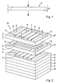
- FIG. 2 shows a stack 20 comprising a multiplicity of stacked catalyst layers 10, 10 ', with the layers at the top in the drawing being shown at a distance from each other for better illustration of the mode of operation.
- the catalyst layers 10 have channels 12, 14, 14 '16 for conducting reactants and products of the catalytic reaction.
- educt channels 12 extending essentially parallel to the longitudinal edges are provided in the catalyst layer, which form continuous guide channels perpendicular to the surface plane of the catalyst layer, the educt channels 12 of superimposed catalyst layers 10, 10 'being essentially congruent to each other and thus form a through the entire stack 20 from top to bottom continuous guide channel for the reactants of the reaction mixture.
- a specific reaction mixture is passed through the educt channels 12.
- the reaction mixture comprises alcohol, in particular methanol, and chemically bonded hydrogen, advantageously in the form of water.
- the reaction mixture comprises carbon monoxide and hydrogen.
- the reaction mixture comprises a CO-containing gas and an O 2 -containing gas.
- the reaction mixture comprises a combustible educt and an O 2 -containing gas.
- each second catalyst layer 10 communicates with distribution channels 14 extending substantially parallel to the surface area of the catalyst layer 10, which at least part of the through the educt channels 12 -. Derive incoming reaction mixture in the interior of the catalyst layer 10.
- a portion of the reaction mixture entering through the reactant channels 12 and passing through the stack 20 in each second layer plane is thus diverted through the distribution channels 14 into the interior of the two adjacent catalyst layers 10, 10 ', whereby a parallel connection of the catalyst layers arranged one above the other is achieved.
- two spatially separate reactant channels 12 are provided per catalyst layer 10, 10 '. This can be used to separate different substances of the reaction mixture supplied separately, so that individual components of the reaction mixture only come together in the plane of the catalyst layer 10.
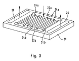
- a catalyst layer is used with a channel structure, as shown in the embodiment of Figure 3.
- the catalyst layer 21 shown in FIG. 3 has reactant channels 22a, 22b and product channels 26, whose function corresponds in principle to the educt and product channels 12 and 16 described in connection with FIG.
- the two educt channels 22a, 22b arranged spatially separate from one another do not communicate with each other through the distribution channels, but the distribution channels 24a or 24b emerging from each of the educt channels 22a, 22b extend transversely over the catalyst layer 21 However, they end before they reach the opposite educt channel 22b or 22a.
- an arrangement of alternating intermeshing channels is created, which can be used for the separate supply of a (further) gas that is needed for or supports the reaction.
- a (further) gas that is needed for or supports the reaction.
- the methanol reformer through the one educt channel, for example supplied to the educt channel 22a, a mixture of methanol and water vapor, it can be fed through the corresponding other educt channel 22b oxygen (air).
- the distribution channels 24a, 24b assigned to the respective educt channel the materials supplied are distributed in the catalyst layer 21 and only come into contact with each other in the layer itself.
- a particularly homogeneous and safe (explosion hazard) distribution and mixing of the educts is achieved.
- other than the illustrated embodiments with only one Eduktkanal or more than two Eduktkanälen are possible.
- product channels 16 Arranged along the transverse edges of the catalyst layers 10, 10 'are product channels 16 formed analogously to the educt channels 12, which likewise form guide channels running essentially perpendicular to the surface area of each catalyst layer 10; 10, 10 'come to rest.
- the superimposed catalyst layers 10, 10 'thus each have alternating modes of operation;
- the educts fed through the educt channels 12 are distributed and distributed via distribution channels 14 over the surface of the above and below the catalyst layer, where they flow through them substantially vertically and under a considerable pressure drop.
- each catalyst layer takes over the feeding, distribution, collection and removal of the educts or products.
- Such more complex catalyst layers can be produced, for example, by pressing and sintering powdered catalyst material onto already sintered catalyst layers.
- catalyst layers are provided which are simple and compact to produce and suitable for use in hydrogen reactors for catalytic hydrogen production, hydrogen shift stages for CO reduction, carbon monoxide oxidizers and catalytic burners.
- the inventive design of the catalyst allows a modular design, in which only small thermal losses and no large temperature gradients occur, whereby a homogenous over a large volume reaction is made possible.
- the total catalyst volume is spatially accessible with educts, which leads to a significantly improved start-up dynamics.
- the risk of ignition of the homogeneous combustion of methanol or the oxyhydrogen gas reaction is avoided.
- the skilled person can tailor-made to the respective requirements and with respect to layer sequence, heat distribution, flow conditions and mechanical properties such as pressure drop and stability optimized catalyst layer or Create catalyst layer assembly.
Description
- Die vorliegende Erfindung betrifft eine Vorrichtung zur Wasserstofferzeugung aus Kohlenwasserstoffen, insbesondere Methanol, unter Zuführung eines Kohlenwasserstoff und Wasser umfassenden Reaktionsgemisches auf einen Katalysator sowie ein Verfahren zur Herstellung eines Katalysators, der insbesondere zur Verwendung in einer derartigen Vorrichtung geeignet ist. Des weiteren betrifft die vorliegende Erfindung eine Vorrichtung zur Kohlenmonoxid-Verringerung, Vorrichtung zur Kohlenmonoxid-Oxidation und eine Vorrichtung zum katalytischen Verbrennen.
- Die Gewinnung von Wasserstoff aus Methanol basiert auf der Gesamtreaktion CH3OH + H2O → CO2 + 3H2. Zur Durchführung dieser Reaktion wird in der Praxis ein den Alkohol und Wasserdampf umfassendes Reaktionsgemisch unter Zufuhr von Wärme an einem geeigneten Katalysator entlanggeleitet, um in einem zwei- oder mehrstufigen Reaktionsablauf den gewünschten Wasserstoff zu erzeugen. Eine derartige Vorrichtung zur zweistufigen Methanol-Reformierung ist aus der
EP 0 687 648 A1 bekannt. In der bekannten Vorrichtung wird das Reaktionsgemisch einem ersten Reaktor zugeführt, in dem nur ein Teilumsatz des Methanols angestrebt wird. Nach dem Durchströmen des ersten Reaktors wird das Gasgemisch, in welchem noch Anteile nicht umgesetzter Edukte enthalten sind, einem zweiten Reaktor zugeleitet, der restumsatzoptimiert aufgebaut ist. Die Reaktoren sind dabei als Platten- bzw. Schüttreaktoren ausgeführt, in welchen der Katalysator in Form einer Schüttung oder Beschichtung der Verteilungskanäle vorgesehen ist. Des weiteren sind Katalysatoren in Form von beschichteten Blechen, Netzen und Schäumen bekannt, die von dem Reaktionsgemisch durchströmt werden. - Aus der
EP 0 217 532 B1 ist ein Verfahren zur katalytischen Erzeugung von Wasserstoff aus Gemischen von Methanol und Sauerstoff unter Verwendung eines gasdurchlässigen Katalysatorsystems bekannt, bei dem ein Wasserstoff-Generator mit einer oberen Reaktionszone und einer unteren Reaktionszone vorgesehen ist, wobei das Reaktionsgemisch von Methanol und Sauerstoff in die obere Reaktionszone eingespeist wird. Nach dem Durchströmen der oberen Reaktionszone wird das Reaktionsgemisch in die untere Reaktionszone geleitet, in welcher es durch eine spontane Einleitung der Oxidation des Methanols zu einem derartigen Anstieg der Temperatur kommt, daß eine teilweise Oxidation des Methanols in Anwesenheit eines Kupfer-Katalysators in der oberen Reaktionszone beginnt und Wasserstoff gebildet wird. - Aus der
DE 195 34 433 C1 ist eine Katalysatorschichtstruktur für einen Methanol-Reformierungsreaktor und ein Verfahren zu deren Herstellung bekannt. Bei der beschriebenen Katalysatorschichtstruktur ist das Katalysatormaterial in den Poren einer verdichteten Metallschaum-Trägerschicht fixiert und dient zum Einsatz in einem Plattenreaktor. - In der Druckschrift
US 4 771 026 ist ein Katalysator in Form einer Platte und ein Verfahren zu dessen Herstellung beschrieben. Bei der Herstellung wird das Katalysatormaterial mit unterschiedlichen Bindemitteln zunächst gemischt und dann verpreßt. - Ausgehend von diesem Stand der Technik liegt der Erfindung die Aufgabe zugrunde, eine jeweils gattungsgemäße Vorrichtung in möglichst einfacher und kompakter Bauweise bereitzustellen, bei der die für die Umsetzung eines bestimmten Mengenstroms an Reaktionsgemisch nötige Menge an Katalysatormaterial minimiert ist. Des weiteren ist es Aufgabe der Erfindung, ein Verfahren zur Herstellung eines Katalysators anzugeben, mit dem die genannte Minimierung an Katalysatormaterial und die einfache und kompakte Bauweise erzielt werden können.
- Zur Lösung dieser Aufgabe wird eine Vorrichtung zur Wasserstofferzeugung aus Kohlenwasserstoffen mit den Merkmalen des Anspruches 1 vorgeschlagen. Zur weiteren Lösung der Aufgabe werden erfindungsgemäß eine Vorrichtung zur Kohlenmonoxid-Verringerung mit den Merkmalen des Anspruches 2, eine Vorrichtung zur Kohlenmonoxid-Oxidation mit den Merkmalen des Anspruches 3 und eine Vorrichtung zum katalytischen Verbrennen mit den Merkmalen des Anspruches 4 vorgeschlagen.
- Die erfindungsgemäßen Vorrichtungen umfassen demnach jeweils einen Katalysator, der durch Verpressen von Katalysatormaterial in mindestens eine dünne und großflächige Schicht gebildet ist, wobei das Reaktionsgemisch beim Hindurchpressen durch den Katalysator einen Druckabfall von mindestens 100 mbar erfährt. Im Unterschied zu den bekannten Wasserstoffreaktoren, Wassergas-Shift-Stufen, Oxidatoren und katalytischen Brennern ist der Katalysator nicht als bloße Oberflächenstruktur ausgebildet, der von dem Reaktionsgemisch nur umströmt wird, sondern als stark komprimierte dreidimensionale Schicht, durch die das Reaktionsgemisch unter starker Druckbeaufschlagung hindurchgepresst wird. Dadurch wird eine hohe Auslastung der aktiven Katalysatorzentren und eine hohe Reaktionsgeschwindigkeit an diesen Zentren erreicht. Aufgrund des starken Druckabfalls beim Durchtritt des Reaktionsgemisches durch die erfindungsgemäße Katalysatorschicht spielen die Strömungswiderstände der Zu- und Ableitung der Edukte und Produkte der Reaktion keine große Rolle, so dass die Zu- und Ableitung der an der Reaktion beteiligten Stoffe einfach gestaltet werden kann. Durch die starke Komprimierung des Katalysatormaterials beim Verpressen wird eine sehr kompakte Katalysatorschicht erzielt, was zur Folge hat, dass der Anteil von Gasraum und nicht katalytisch wirksamen Festkörpern (wie beispielsweise Trägerbleche und dergleichen) am Gesamtvolumen und Gewicht des Reaktors gegenüber bekannten Vorrichtungen deutlich verringert ist. Vorzugsweise wird als Katalysatormaterial feinkörniges Katalysatorgranulat bzw. -pulver verwendet. Dadurch wird auch bei hohen Reaktionsgeschwindigkeiten ein guter Stoff- und Wärmetransport zu und von den inneren Bereichen der Katalysatorkörner gewährleistet. Au-ßerdem nimmt der Anteil der durchströmbaren Poren mit abnehmender Korngröße zu, d.h. die Anzahl der "Sackgassen" für die Gasdurchströmung nimmt ab. Beim Durchströmen der Schicht tritt eine starke Verwirbelung der Gase auf, wodurch die Filmdiffusionswiderstände um die Körner des Katalysatormaterials verringert werden, was zu einem verbesserten Wärmetransport durch Konvektion führt.
- In Ausgestaltung der Erfindung ist die Katalysatorschicht im wesentlichen senkrecht zur Strömungsrichtung des Reaktionsgemisches angeordnet. Dadurch werden besonders kurze Wege für die Gasdurchströmung erzielt. Durch die großflächige und stark komprimierte Ausgestaltung der erfindungsgemäßen Katalysatorschicht genügt bei senkrechter Durchströmung bereits ein kurzer Weg, um unter hohem Druckabfall einen hohen Reaktionsumsatz zu erzielen.
- In besonders vorteilhafter Ausgestaltung der Erfindung ist das Katalysatormaterial mit einer Trägerstruktur verpreßt, wodurch das Katalysatormaterial mechanisch stabilisiert ist und/oder eine verbesserte Wärmeleitung vorliegt. Bei der Trägerstruktur handelt es sich vorteilhafterweise um eine dreidimensionale netzartige Struktur (Matrix), die in weiterer vorteilhafter Ausgestaltung der Erfindung eine metallene Trägerstruktur ist. Als Metall wird beispielsweise Kupfer, insbesondere dendritisches Kupfer verwendet.
- In vorteilhafter Ausgestaltung der Erfindung enthält das Katalysatormaterial ein Edelmetall, insbesondere Platin. Das zugesetzte Edelmetall, bei dem es sich vorzugsweise um Platin handelt, wobei jedoch auch die Verwendung anderer Edelmetalle möglich ist, reagiert bereits bei relativ niederen Betriebstemperaturen und dient somit zur Aufheizung der Katalysatoranordnung. Durch diese Maßnahme wird das Kaltstartverhalten der Katalysatoranordnung beträchtlich verbessert, was sich insbesondere bei einer Anwendung im Bereich der mobilen Wasserstofferzeugung vorteilhaft auswirkt.
- In besonders vorteilhafter Weiterbildung der Erfindung sind mehrere parallel geschaltete Schichten vorgesehen. Dadurch kann die insgesamt von dem Reaktionsgemisch zu durchströmende Fläche auf mehrere nachgeordnete, jedoch parallel geschaltete Schichten verteilt werden. Diese "Modulbauweise" führt zu einem besonders kompakten Aufbau des Wasserstoffreaktors.
- Zur vereinfachten Zu- und Ableitung der an der Reaktion beteiligten Stoffe sind in weiterer Ausgestaltung der Erfindung in der mindestens einen Katalysatorschicht Kanäle zum Leiten von Edukten des Reaktionsgemisches und der Reaktionsprodukte vorgesehen.
- Bei der Nutzung der erfindungsgemäßen Vorrichtung erfolgt eine gegebenenfalls reaktionsbenötigte oder reaktionsfördernde Zuführung von Sauerstoff zu dem Reaktionsgemisch erst in der Ebene der mindestens einen Katalysatorschicht.
- Zur weiteren Lösung der Erfindung wird ein Verfahren mit den Merkmalen des Anspruches 15 vorgeschlagen. Erfindungsgemäß wird demnach zur Herstellung eines insbesondere in einer erfindungsgemäßen Vorrichtung nach einem der Ansprüche 1 bis 4 verwendbaren Katalysators aus mindestens einem Katalysatorpulver durch Verpressen eine einen Formkörper bildende und stark komprimierte Schicht gebildet durch die ein Reaktionsgemisch unter einem Druckabfall von mindestens 100 mbar hindurchpressbar ist.
- In vorteilhafter Ausgestaltung der Erfindung ist dem mindestens einen Katalysatorpulver ein Metallpulver (beispielsweise Kupfer oder dendritisches Kupfer) beigemischt.
- In Ausgestaltung der Erfindung wird der Formkörper im Anschluss an das Verpressen einer Sinterung unterzogen, wodurch eine besonders gute Beständigkeit des erfindungsgemäßen Katalysators erreicht wird.
- In weiterer Ausgestaltung der Erfindung werden beim Verpressen in den Formkörper Kanäle zum Leiten von Edukten und Produkten der katalytischen Reaktion eingebracht. Vorteilhafterweise werden diese Kanäle durch Einbringen von in einem nachfolgenden Verfahrensschritt wieder entfernbaren Platzhalterelementen erzeugt. Das Entfernen der Platzhalterelemente erfolgt vorteilhafterweise durch Verbrennen, Pyrolysieren, Lösen oder Verdampfen.
- In weiterer vorteilhafter Ausgestaltung der Erfindung wird auf einem bereits gesinterten Formkörper eine weitere Pulverschicht aufgepreßt und anschließend gesintert. Dadurch kann in mehrstufiger Herstellung in einer Art Sandwichstruktur ein Katalysator mit mehreren übereinanderliegenden Schichten hergestellt werden, die durch Einbringen geeigneter Kanäle parallel verschaltet sind. Dadurch kann das gesamte von dem Reaktionsgemisch zu durchfließende Katalysatorvolumen auf eine kleinere Querschnittsfläche aufgeteilt und trotzdem das Konzept des hohen Druckabfalls über einen kleinen Strömungsweg beibehalten werden.
- Die Erfindung ist anhand von Ausführungsbeispielen in der Zeichnung schematisch dargestellt und wird im folgenden unter Bezugnahme auf die Zeichnung ausführlich beschrieben.
- Figur 1
- veranschaulicht in stark schematischer Darstellung die Funktionsweise einer erfindungsgemäßen Katalysatorschicht.
- Figur 2
- zeigt in perspektivischer Darstellung eine erfindungsgemäße stapelförmige Anordnung parallel geschalteter Katalysatorschichten.
- Figur 3
- zeigt in perspektivischer Darstellung ein weiteres Ausführungsbeispiel einer einzelnen erfindungsgemäßen Katalysatorschicht.
- Figur 1 zeigt schematisch in seitlicher Ansicht eine erfindungsgemäße Katalysatorschicht 10, die durch Verpressen von Katalysatormaterial in eine dünne und großflächige, stark komprimierte Schicht gebildet ist. Die Schicht 10 bildet einen Formkörper mit einer Dicke d, die beispielsweise 1 mm beträgt. Als Katalysatormaterial wird ein feinkörniges Katalysatorpulver oder -granulat verwendet, dessen Körner einen Durchmesser von ca. 0,5 mm oder kleiner haben. Das Verpressen erfolgt beispielsweise bei Temperaturen von ca. 200° bis 500°C.
- Die dargestellte Katalysatorschicht 10 ist Bestandteil einer nicht näher dargestellten Vorrichtung zur Wasserstofferzeugung, wobei die Edukte des Reaktionsgemisches unter Druckbeaufschlagung im wesentlichen senkrecht zu der Katalysatorschicht 10 auf diese zugeführt und durch sie hindurchgepreßt werden. Beim Durchströmen der Katalysatorschicht 10 erfährt das Reaktionsgemisch einen Druckabfall Δp von ca. 100 mbar und mehr (beispielsweise 1 bis 4 bar). Auf der gegenüberliegenden Seite der Katalysatorschicht 10 treten die katalytischen Reaktionsprodukte im Sinne des eingezeichneten Pfeiles aus.
- Um dem Katalysatormaterial eine bessere mechanische Stabilität und/oder verbesserte Wärmeleitung zu verleihen, wird das Katalysatormaterial in eine Trägerstruktur verpreßt. Bei dieser Trägerstruktur handelt es sich vorteilhafterweise um eine netzartige Matrix, die durch Vermischen des mindestens einen Katalysatorpulvers mit einem Metallpulver und Verpressen dieses Gemisches erhalten wird. Beim Verpressen bildet das Metallpulver (insbesondere Kupfer oder dendritisches Kupfer) eine netzartige Matrixstruktur, in welche die Katalysatorkörner "eingebaut" sind. Besonders geeignet als Ausgangsmaterial für die metallene Matrix sind dendritische Kupferpulver, die sich auch bei einem relativ geringen Massenanteil des Kupferpulvers zur Gesamtmasse der Schicht leicht zu einem Netz zusammenpressen bzw. versintern lassen, eine große Oberfläche haben und selber katalytisch aktiv sind. Durch die Verwendung von dendritischem Kupferpulver wird deshalb ein stabilisierendes, fixierendes und wärmeverteilendes Netz im Mikrometer-Bereich erhalten. Als Trägerstruktur sind jedoch auch nicht-metallene Materialien wie beispielsweise Kohlenstoff denkbar.
- Die Katalysatorschicht 10 weist eine relativ große Fläche von beispielsweise 100 cm2 auf. Um eine kompaktere Bauweise zu erreichen, wird das von dem Reaktionsgemisch zu durchfließende Katalysatorvolumen auf mehrere Schichten aufgeteilt, die jedoch nicht nebeneinander, sondern hintereinander, aber parallel geschaltet angeordnet sind. Eine derartige Anordnung ist in Figur 2 dargestellt und zeigt einen eine Vielzahl von aufeinanderliegenden Katalysatorschichten 10, 10' umfassenden Stapel 20, wobei die in der Zeichnung oben liegenden Schichten zur besseren Veranschaulichung der Wirkungsweise beabstandet zueinander dargestellt sind.
- Die Katalysatorschichten 10 weisen Kanäle 12, 14, 14' 16 zum Leiten von Edukten und Produkten der katalytischen Reaktion auf. In dem in Figur 2 dargestellten Ausführungsbeispiel sind in der Katalysatorschicht im wesentlichen parallel zu den Längskanten verlaufende Eduktkanäle 12 vorgesehen, die senkrecht zur Flächenebene der Katalysatorschicht durchgehende Führungskanäle bilden, wobei die Eduktkanäle 12 übereinanderliegender Katalysatorschichten 10, 10' im wesentlichen deckungsgleich zueinander angeordnet sind und somit einen durch den gesamten Stapel 20 von oben nach unten durchgehenden Führungskanal für die Edukte des Reaktionsgemisches bilden. Je nach Verwendung der Stapelanordnung wird durch die Eduktkanäle 12 ein spezifisches Reaktionsgemisch geleitet. Im Falle der Verwendung als Wasserstoffreaktor umfaßt das Reaktionsgemisch Alkohol, insbesondere Methanol, sowie chemisch gebundenen Wasserstoff, vorteilhafterweise in Form von Wasser. Im Falle der Verwendung des Stapels 20 in einer sogenannten H2-Shift-Reaktion zur Verringerung von Kohlenmonoxid unter Freisetzung von Kohlendioxid umfaßt das Reaktionsgemisch Kohlenmonoxid und Wasserstoff. Im Falle des Einsatzes im Bereich der Kohlenmonoxid-Oxidation umfaßt das Reaktionsgemisch ein CO-haltiges Gas sowie ein O2-haltiges Gas. Bei der Verwendung des Katalysatorstapels 20 in einem katalytischen Brenner umfaßt das Reaktionsgemisch ein brennbares Edukt sowie ein O2-haltiges Gas.
- Die Eduktkanäle 12 jeder zweiten Katalysatorschicht 10 stehen mit im wesentlichen parallel zur Flächenausdehnung der Katalysatorschicht 10 verlaufenden Verteilungskanälen 14 in Verbindung, die wenigstens einen Teil des durch die Eduktkanäle 12 - eintretenden Reaktionsgemisches in das Innere der Katalysatorschicht 10 ableiten.
- Erfindungsgemäß wird demnach jeweils ein Teil des durch die Eduktkanäle 12 eintretenden und durch den Stapel 20 geführten Reaktionsgemisches in jeder zweiten Schichtenebene durch die Verteilungskanäle 14 in das Innere der beiden angrenzenden Katalysatorschichten 10, 10' abgeleitet, wodurch eine Parallelschaltung der übereinanderliegend angeordneten Katalysatorschichten erreicht wird.
- In dem in der Figur 2 dargestellten Ausführungsbeispiel sind wie beschrieben pro Katalysatorschicht 10, 10' zwei räumlich getrennte Eduktkanäle 12 vorgesehen. Dies kann dazu genutzt werden, um verschiedene Stoffe des Reaktionsgemisches getrennt voneinander zuzuführen, so daß einzelne Bestandteile des Reaktionsgemisches erst in der Ebene der Katalysatorschicht 10 zusammenkommen.
- Vorteilhafterweise wird hierzu eine Katalysatorschicht mit einer Kanalstruktur eingesetzt, wie sie in dem Ausführungsbeispiel der Figur 3 dargestellt ist. Die in Figur 3 gezeigte Katalysatorschicht 21 weist Eduktkanäle 22a, 22b und Produktkanäle 26 auf, die in ihrer Funktion prinzipiell den in Zusammenhang mit der Figur 2 beschriebenen Edukt- und Produktkanälen 12 und 16 entsprechen. Abweichend von der in Figur 2 dargestellten Katalysatorschicht 10 stehen die zwei räumlich getrennt voneinander angeordneten Eduktkanäle 22a, 22b durch die Verteilungskanäle nicht miteinander in Verbindung, sondern die von jedem der Eduktkanäle 22a, 22b ausgehenden Verteilungskanäle 24a bzw. 24b erstrecken sich quer über die Katalysatorschicht 21, enden jedoch, bevor sie den gegenüberliegenden Eduktkanal 22b bzw. 22a erreichen. Dadurch wird eine Anordnung von alternierend ineinandergreifenden Kanälen geschaffen, was zur separaten Zuführung eines (weiteren) Gases, das zur Reaktion benötigt wird oder diese unterstützt, genutzt werden kann. Wird im Beispieldes Methanol-Reformers durch den einen Eduktkanal, beispielsweise den Eduktkanal 22a, eine Mischung aus Methanol und Wasserdampf zugeführt, so kann durch den entsprechend anderen Eduktkanal 22b Sauerstoff (Luft) zugeführt werden. Über die dem jeweiligen Eduktkanal zugeordneten Verteilungskanäle 24a, 24b werden die zugeleiteten Stoffe in der Katalysatorschicht 21 verteilt und treten erst in der Schicht selbst miteinander in Kontakt. Dadurch wird eine besonders homogene und sichere (Explosionsgefahr) Verteilung und Vermischung der Edukte erreicht. Selbstverständlich sind auch andere als die dargestellte Ausführungsformen mit nur einem Eduktkanal oder auch mehr als zwei Eduktkanälen möglich.
- Entlang der Querkanten der Katalysatorschichten 10, 10' sind analog zu den Eduktkanälen 12 ausgebildete Produktkanäle 16 angeordnet, die ebenfalls im wesentlichen senkrecht zur Flächenausdehnung jeder Katalysatorschicht 10 verlaufende Führungskanäle bilden, die bei übereinandergelegten Katalysatorschichten 10 jeweils deckungsgleich mit den Produktkanälen der darüber bzw. darunterliegenden Katalysatorschicht 10, 10' zum Liegen kommen. Die Produktkanäle 16 jeder zweiten Katalysatorschicht 10' stehen mit Sammelkanälen 14' in Verbindung, die das aus der jeweils darüber- und darunterliegenden Katalysatorschicht 10, 10' austretende Reaktionsprodukt sammeln und in Querrichtung den Produktkanälen 16 zuführen, mittels welcher die Reaktionsprodukte durch den Stapel 20 abgeleitet werden.
- In der dargestellten Ausführungsform einer erfindungsgemäßen Vorrichtung zur Wasserstofferzeugung verfügen die übereinandergelegten Katalysatorschichten 10, 10' also über jeweils alternierende Funktionsweisen; in den Katalysatorschichten 10 werden die durch die Eduktkanäle 12 zugeführten Edukte verteilt und über Verteilungskanäle 14 über die Fläche der darüber- und darunterliegenden Katalysatorschicht verteilt, wo sie diese im wesentlichen senkrecht und unter einem beträchtlichen Druckabfall durchströmen. In der jeweils folgenden Katalysatorschicht 10' werden die Produkte der katalytischen Reaktion in Sammelkanälen 14' gesammelt und den Produktkanälen 16 zum Abführen der Reaktionsprodukte aus dem Katalysatorstapel 20 zugeführt.
- Natürlich ist die Erfindung nicht auf die dargestellte und beschriebene Ausführungsform beschränkt. Vielmehr sind auch Ausführungsformen denkbar, in welchen jede Katalysatorschicht das Zuführen, Verteilen, Sammeln und Abführen der Edukte bzw. Produkte übernimmt. Derartige komplexere Katalysatorschichten können beispielsweise durch Aufpressen und Sintern von pulverförmigen Katalysatormaterial auf bereits gesinterte Katalysatorschichten hergestellt werden.
- Erfindungsgemäß werden somit Katalysatorschichten bereitgestellt, die einfach und in kompakter Weise herstellbar und zur Verwendung in Wasserstoffreaktoren zur katalytischen Wasserstofferzeugung, Wasserstoff-Shift-Stufen zur CO-Verringerung, Kohlenmonoxid-Oxidatoren sowie katalytischen Brennern geeignet sind. Durch die erfindungsgemäße Ausgestaltung des Katalysators wird eine modulare Bauweise ermöglicht, bei dem nur geringe thermische Verluste und keine großen Temperaturgradienten auftreten, wodurch eine über ein großes Volumen homogen ablaufende Reaktion ermöglicht wird. Das gesamte Katalysatorvolumen ist räumlich mit Edukten erreichbar, was zu einer deutlich verbesserten Startdynamik führt. Darüber hinaus wird die Gefahr der Zündung der homogenen Verbrennung von Methanol oder der Knallgasreaktion vermieden.
- Durch geeignete Wahl der Prozeßparameter (Preßdruck, Temperatur, Art und Beschaffenheit der Ausgangsmaterialien wie Korngrößenverteilung, Porösität etc.) kann der Fachmann eine auf die jeweiligen Anforderungen zugeschnittene und bezüglich Schichtfolge, Wärmeverteilung, Strömungsverhältnisse und mechanische Eigenschaften wie Druckabfall und Stabilität optimierte erfindungsgemäße Katalysatorschicht bzw. Katalysatorschichtenanordnung erzeugen.
Claims (22)
- Vorrichtung zur Wasserstofferzeugung unter Zuführung eines chemisch gebundenen Wasserstoff enthaltenden Brennmittels, insbesondere Methanol, und Wasser umfassenden Reaktionsgemisches auf einen Katalysator,
dadurch gekennzeichnet, dass
der Katalysator mindestens eine durch Verpressen und Sinterung von Katalysatormaterial gebildete dünne und großflächige Schicht (10, 10'; 21) ist, wobei das Reaktionsgemisch beim Hindurchpressen durch den Katalysator einen Druckabfall (Δp) erfährt. - Vorrichtung zur Kohlenmonoxid-Verringerung unter Zuführung eines Kohlenmonoxid und Wasserstoff umfassenden Reaktionsgemisches auf einen Katalysator,
dadurch gekennzeichnet, dass
der Katalysator mindestens eine durch Verpressen und Sinterung von Katalysatormaterial gebildete dünne und großflächige Schicht (10, 10'; 21) ist, wobei das Reaktionsgemisch beim Hindurchpressen durch den Katalysator einen Druckabfall (Δp) erfährt. - Vorrichtung zur Kohlenmonoxid-Oxidation unter Zuführung eines Kohlenmonoxid und Sauerstoff umfassenden Reaktionsgemisches auf einen Katalysator,
dadurch gekennzeichnet, dass
der Katalysator mindestens eine durch Verpressen und Sinterung von Katalysatormaterial gebildete dünne und großflächige Schicht (10, 10'; 21) ist, wobei das Reaktionsgemisch beim Hindurchpressen durch den Katalysator einen Druckabfall (Δp) erfährt. - Vorrichtung zum katalytischen Verbrennen eines brennbaren Eduktes unter Zuführung eines das brennbare Edukt und sauerstoffhaltiges Gas umfassenden Reaktionsgemisches auf einen Katalysator,
dadurch gekennzeichnet, dass
der Katalysator mindestens eine durch Verpressen und Sinterung von Katalysatormaterial gebildete dünne und großflächige Schicht (10, 10'; 21) ist, wobei das Reaktionsgemisch beim Hindurchpressen durch den Katalysator einen Druckabfall (Δp) erfährt. - Vorrichtung nach einem der Ansprüche 1 bis 4,
dadurch gekennzeichnet, dass
die Schicht (10, 10'; 21) im Wesentlichen senkrecht zur Strömungsrichtung des Reaktionsgemisches angeordnet ist. - Vorrichtung nach einem der Ansprüche 1 bis 5,
dadurch gekennzeichnet, dass
das Katalysatormaterial mit einer Trägerstruktur verpresst ist. - Vorrichtung nach Anspruch 6,
dadurch gekennzeichnet, dass
die Trägerstruktur eine netzartige metallene Trägerstruktur ist. - Vorrichtung nach Anspruch 7,
dadurch gekennzeichnet, dass
die netzartige Trägerstruktur aus Kupfer ist. - Vorrichtung nach Anspruch 8,
dadurch gekennzeichnet, dass
die netzartige Trägerstruktur aus dendritischem Kupfer ist. - Vorrichtung nach einem der vorstehenden Ansprüche,
dadurch gekennzeichnet, dass
das Katalysatormaterial ein Edelmetall, insbesondere Platin, enthält. - Vorrichtung nach einem der vorstehenden Ansprüche,
dadurch gekennzeichnet,
dass mehrere parallel geschaltete Schichten (10, 10'; 21) vorgesehen sind. - Vorrichtung nach einem der vorstehenden Ansprüche,
dadurch gekennzeichnet, dass
in der mindestens einen Schicht (10, 10'; 21) Kanäle (12, 14, 14', 16; 22a, 22b, 24a, 24b, 26) zum Leiten von Edukten des Reaktionsgemisches und der Reaktionsprodukte vorgesehen sind. - Verfahren zur Nutzung einer Vorrichtung nach einem der Ansprüche 1 bis 12,
dadurch gekennzeichnet, dass
eine Zuführung von Sauerstoff getrennt von den übrigen Edukten erfolgt. - Verfahren nach Anspruch 13,
dadurch gekennzeichnet, dass
ein Zusammenführen und Mischen des Sauerstoffs mit den übrigen Edukten erst in der Schicht (10, 21) erfolgt. - Verfahren zur Herstellung eines Katalysators, insbesondere für eine Vorrichtung nach einem der Ansprüche 1 bis 12, bei dem aus mindestens einem Katalysatorpulver durch Verpressen und anschließender Sinterung eine einen Formkörper bildende dünne und stark komprimierte Schicht (10, 10') gebildet wird, durch die ein Reaktionsgemisch unter einem Druckabfall hindurchpressbar ist.
- Verfahren nach Anspruch 15, bei dem dem mindestens einen Katalysatorpulver ein Metallpulver beigemischt ist.
- Verfahren nach Anspruch 16, bei dem das Metallpulver Kupferpulver ist.
- Verfahren nach Anspruch 17, bei dem das Metallpulver aus dendritischem Kupfer ist.
- Verfahren nach einem der Ansprüche 15 bis 18, bei dem beim Verpressen in den Formkörper Kanäle (12, 14, 14', 16; 22a, 22b, 24a, 24b, 26) zum Leiten von Edukten und Produkten der katalytischen Reaktion eingebracht werden.
- Verfahren nach Anspruch 19, bei dem die Kanäle (12, 14, 14', 16; 22a, 22b, 24a, 24b, 26) durch Einbringen von in einem nachfolgenden Verfahrensschritt wieder entfernbaren Platzhalterelementen erzeugt werden.
- Verfahren nach Anspruch 20, bei dem die Platzhalterelemente durch Verbrennen, Pyrolysieren, Lösen oder Verdampfen entfernt werden.
- Verfahren nach einem der Ansprüche 15 bis 21, bei dem auf einen bereits gesinterten Formkörper eine weitere Pulverschicht aufgepresst und anschließend gesintert wird.
Applications Claiming Priority (2)
| Application Number | Priority Date | Filing Date | Title |
|---|---|---|---|
| DE19743673 | 1997-10-02 | ||
| DE19743673A DE19743673C2 (de) | 1997-10-02 | 1997-10-02 | Vorrichtung zur Wasserstofferzeugung aus Kohlenwasserstoffen und Verfahren zur Herstellung eines Katalysators |
Publications (2)
| Publication Number | Publication Date |
|---|---|
| EP0906890A1 EP0906890A1 (de) | 1999-04-07 |
| EP0906890B1 true EP0906890B1 (de) | 2007-07-04 |
Family
ID=7844464
Family Applications (2)
| Application Number | Title | Priority Date | Filing Date |
|---|---|---|---|
| EP98951381A Expired - Lifetime EP1019183B1 (de) | 1997-10-02 | 1998-09-11 | Vorrichtung zur durchführung einer heterogen katalysierten reaktion und verfahren zur herstellung eines katalysators |
| EP98118264A Expired - Lifetime EP0906890B1 (de) | 1997-10-02 | 1998-09-26 | Vorrichtung zur Wasserstofferzeugung,Vorrichtung zur Kohlenmonoxid-Verringerung,Vorrichtung zur Kohlenmonoxid-Oxidation,Vorrichtung zum katalytischen Verbrennen und Verfahren zur Herstellung eines Katalysators |
Family Applications Before (1)
| Application Number | Title | Priority Date | Filing Date |
|---|---|---|---|
| EP98951381A Expired - Lifetime EP1019183B1 (de) | 1997-10-02 | 1998-09-11 | Vorrichtung zur durchführung einer heterogen katalysierten reaktion und verfahren zur herstellung eines katalysators |
Country Status (5)
| Country | Link |
|---|---|
| US (3) | US6660685B1 (de) |
| EP (2) | EP1019183B1 (de) |
| JP (2) | JP3497132B2 (de) |
| DE (3) | DE19743673C2 (de) |
| WO (1) | WO1999017867A2 (de) |
Families Citing this family (38)
| Publication number | Priority date | Publication date | Assignee | Title |
|---|---|---|---|---|
| DE19743673C2 (de) * | 1997-10-02 | 2002-05-08 | Xcellsis Gmbh | Vorrichtung zur Wasserstofferzeugung aus Kohlenwasserstoffen und Verfahren zur Herstellung eines Katalysators |
| DE19832625C2 (de) * | 1998-07-21 | 2001-05-17 | Xcellsis Gmbh | Verfahren zur Herstellung eines Stapelreaktors und Stapelreaktor zur Wasserstofferzeugung aus Kohlenwasserstoffen |
| DE19847987C2 (de) * | 1998-10-17 | 2001-06-13 | Xcellsis Gmbh | Verfahren zur Herstellung einer Vorrichtung zur Wasserstofferzeugung und Vorrichtung zur Wasserstofferzeugung |
| DE19906672C2 (de) * | 1999-02-18 | 2003-05-08 | Ballard Power Systems | Vorrichtung zur Durchführung einer katalytischen Reaktion |
| EP1085260A1 (de) | 1999-09-15 | 2001-03-21 | XCELLSIS GmbH | Verdampfer |
| DE19944185A1 (de) | 1999-09-15 | 2001-03-29 | Xcellsis Gmbh | Vorrichtung zur Durchführung einer heterogen katalysierten Reaktion und Verfahren zu deren Herstellung |
| DE19944187A1 (de) * | 1999-09-15 | 2001-03-29 | Xcellsis Gmbh | Gaserzeugungssystem |
| DE19944186A1 (de) * | 1999-09-15 | 2001-03-29 | Xcellsis Gmbh | Vorrichtung zum Erwärmen und/oder Umsetzen wenigstens eines Mediums |
| US7300635B2 (en) | 2000-01-11 | 2007-11-27 | Compactgtl Plc | Catalytic reactor |
| DE10010070A1 (de) * | 2000-03-02 | 2001-09-20 | Xcellsis Gmbh | Gaserzeugungsvorrichtung |
| FR2807746B1 (fr) * | 2000-04-13 | 2002-12-13 | Air Liquide | Procede de production d'un melange comportant de l'hydrogene et du co |
| DE10028865C2 (de) * | 2000-06-10 | 2002-09-26 | Xcellsis Gmbh | Vorrichtung zur katalytischen Wasserstofferzeugung aus Kohlenwasserstoffen |
| DE10038525C2 (de) | 2000-08-08 | 2002-11-21 | Ballard Power Systems | Katalysatoranschlußscheibe für einen Stapelreaktor und Verfahren zur Herstellung der Katalysatoranschlußscheibe |
| DE10046692C2 (de) | 2000-09-21 | 2003-09-18 | Ballard Power Systems | Vorrichtung zur Verdampfung einer Flüssigkeit |
| WO2002071451A2 (en) | 2001-03-02 | 2002-09-12 | Mesosystems Technology, Inc. | Ammonia-based hydrogen generation apparatus and method for using same |
| US7922781B2 (en) | 2001-03-02 | 2011-04-12 | Chellappa Anand S | Hydrogen generation apparatus and method for using same |
| US7867300B2 (en) | 2001-03-02 | 2011-01-11 | Intelligent Energy, Inc. | Ammonia-based hydrogen generation apparatus and method for using same |
| DE10132673A1 (de) * | 2001-07-05 | 2003-01-16 | Ballard Power Systems | Reaktor zur katalytischen Umsetzung eines Brennmittels |
| DE10134647A1 (de) * | 2001-07-17 | 2003-02-06 | Ballard Power Systems | Vorrichtung zur selektiven Oxidation eines Stoffstroms |
| US8172913B2 (en) | 2002-04-23 | 2012-05-08 | Vencill Thomas R | Array of planar membrane modules for producing hydrogen |
| JP2007536711A (ja) * | 2004-05-07 | 2007-12-13 | アーディカ・テクノロジーズ・インコーポレイテッド | 電気デバイス用のオンデマンド電源を備えた衣類及び個人用機器 |
| US20060201148A1 (en) * | 2004-12-07 | 2006-09-14 | Zabtcioglu Fikret M | Hydraulic-compression power cogeneration system and method |
| WO2006109949A1 (en) * | 2005-04-01 | 2006-10-19 | Lg Chem, Ltd. | Hydrogen generating apparatus and hydrogen generating method using the hydrogen generating apparatus |
| US8795926B2 (en) | 2005-08-11 | 2014-08-05 | Intelligent Energy Limited | Pump assembly for a fuel cell system |
| US20070036711A1 (en) * | 2005-08-11 | 2007-02-15 | Ardica Technologies Inc. | Hydrogen generator |
| US8187758B2 (en) * | 2005-08-11 | 2012-05-29 | Ardica Technologies Inc. | Fuel cell apparatus with a split pump |
| FR2896494B1 (fr) * | 2006-01-23 | 2008-12-26 | Renault Sas | Dispositif pour la production d'hydrogene |
| WO2009097146A1 (en) * | 2008-01-29 | 2009-08-06 | Ardica Technologies, Inc. | A system for purging non-fuel material from fuel cell anodes |
| US9034531B2 (en) | 2008-01-29 | 2015-05-19 | Ardica Technologies, Inc. | Controller for fuel cell operation |
| US20100053852A1 (en) * | 2008-09-02 | 2010-03-04 | Cheng Uei Precision Industry Co., Ltd. | Display Device |
| US8741004B2 (en) | 2009-07-23 | 2014-06-03 | Intelligent Energy Limited | Cartridge for controlled production of hydrogen |
| US20110020215A1 (en) * | 2009-07-23 | 2011-01-27 | Ryu Wonhyoung | Chemical hydride formulation and system design for controlled generation of hydrogen |
| US8808410B2 (en) | 2009-07-23 | 2014-08-19 | Intelligent Energy Limited | Hydrogen generator and product conditioning method |
| US20110053016A1 (en) * | 2009-08-25 | 2011-03-03 | Daniel Braithwaite | Method for Manufacturing and Distributing Hydrogen Storage Compositions |
| US8940458B2 (en) | 2010-10-20 | 2015-01-27 | Intelligent Energy Limited | Fuel supply for a fuel cell |
| US9169976B2 (en) | 2011-11-21 | 2015-10-27 | Ardica Technologies, Inc. | Method of manufacture of a metal hydride fuel supply |
| GB2527592A (en) * | 2014-06-27 | 2015-12-30 | Compactgtl Ltd | Catalytic reactors |
| DE102017001565B4 (de) | 2017-02-20 | 2022-05-19 | Diehl Aerospace Gmbh | Verdampfer |
Family Cites Families (34)
| Publication number | Priority date | Publication date | Assignee | Title |
|---|---|---|---|---|
| US3228892A (en) * | 1960-12-29 | 1966-01-11 | Texaco Inc | Method for preparing supported catalytic structures |
| US3334962A (en) * | 1962-10-08 | 1967-08-08 | Nat Lead Co | Process for the production of cubic crystalline zirconia |
| US3397154A (en) * | 1963-07-09 | 1968-08-13 | Du Pont | Preparation of alumina-supported catalyst compositions and the products thereof |
| US3716414A (en) * | 1970-08-12 | 1973-02-13 | Catalytic Technology Corp | 100-watt fuel cell |
| DE2363888A1 (de) * | 1973-12-21 | 1975-07-03 | Auer Hans Heinrich | Vorrichtung mit rotierenden werkzeugen zur kontinuierlichen behandlung von stoffen in fliessfaehiger form |
| IT1070099B (it) * | 1975-09-23 | 1985-03-25 | Degussa | Catalizzatore supportato monolitico e disposizione di catalizzatori supportati monolitici per la depurazione dei gas di scarico di motori a combustione |
| FR2328656A1 (fr) * | 1975-10-22 | 1977-05-20 | Azote & Prod Chim | Nouveau catalyseur de reformage a la vapeur |
| US4214954A (en) * | 1978-12-04 | 1980-07-29 | Olin Corporation | Plated metallic cathode with porous copper subplating |
| US4233187A (en) * | 1979-03-26 | 1980-11-11 | United Catalysts Inc. | Catalyst and process for steam-reforming of hydrocarbons |
| US4460704A (en) * | 1980-06-15 | 1984-07-17 | Imperial Chemical Industries Plc | Catalyst for the production of hydrogen |
| JPS5826004A (ja) * | 1981-08-10 | 1983-02-16 | Kansai Coke & Chem Co Ltd | 水素ガスを主成分とする含酸素ガスから酸素を除去する方法 |
| JPS59122807A (ja) * | 1982-12-28 | 1984-07-16 | Matsushita Electric Ind Co Ltd | 触媒燃焼器 |
| DE3521766A1 (de) * | 1985-06-19 | 1987-01-02 | Basf Ag | Wabenfoermiger katalysator, seiner herstellung und seine verwendung |
| JPS6230554A (ja) | 1985-07-31 | 1987-02-09 | Choichi Furuya | 気・気反応用撥水性微細孔性触媒及びそれを使用した気・気反応方法 |
| GB8521953D0 (en) | 1985-09-04 | 1985-10-09 | Johnson Matthey Plc | Catalytic hydrogen generator |
| JPS62160121A (ja) * | 1985-12-28 | 1987-07-16 | Ngk Insulators Ltd | 多孔質隔膜 |
| DE3608635A1 (de) * | 1986-03-14 | 1987-09-17 | Drache Keramikfilter | Abgasreaktor und verfahren zu seiner herstellung |
| DE3624934A1 (de) * | 1986-07-23 | 1988-01-28 | Dynamit Nobel Ag | Bei hohen temperaturen bestaendige katalysator-formkoerper und verfahren zu deren herstellung |
| DE3633515A1 (de) * | 1986-10-02 | 1988-04-14 | Didier Werke Ag | Katalysator in form einer platte fuer die stickoxidreduzierung in abgasen |
| EP0303438A3 (de) * | 1987-08-14 | 1989-12-27 | DAVY McKEE CORPORATION | Herstellung von Synthesegas aus kohlenwasserstoffhaltigem Rohrstoff |
| JPH0675376B2 (ja) * | 1988-09-01 | 1994-09-21 | 株式会社東芝 | マグネトロンの製造方法 |
| DE3928790A1 (de) * | 1989-08-31 | 1991-03-07 | Didier Werke Ag | Verfahren zum herstellen einer katalysatorplatte und stuetzgeruest zur herstellung einer katalysatorplatte |
| US5281462A (en) * | 1989-11-01 | 1994-01-25 | Corning Incorporated | Material, structure, filter and catalytic converter |
| JPH04207905A (ja) | 1990-11-30 | 1992-07-29 | Railway Technical Res Inst | 鉄道車両用ブレーキ制御装置 |
| DE4207905A1 (de) | 1992-03-12 | 1993-09-16 | Bayer Ag | Festbettreaktoren mit kurzem katalysatorbett in stroemungsrichtung |
| JPH06172029A (ja) * | 1992-12-03 | 1994-06-21 | Sumitomo Metal Ind Ltd | 炭素・金属複合材およびその製造方法 |
| JP3092836B2 (ja) | 1993-09-30 | 2000-09-25 | タムラ化研株式会社 | 導電性組成物 |
| DE4334981C2 (de) * | 1993-10-14 | 1998-02-26 | Daimler Benz Ag | Verwendung eines Reaktors zur katalytischen Entfernung von CO in H¶2¶-reichem Gas |
| DE59503581D1 (de) * | 1994-06-15 | 1998-10-22 | Dbb Fuel Cell Engines Gmbh | Zweistufige Methanol-Reformierung |
| JPH08199109A (ja) | 1995-01-23 | 1996-08-06 | Tokuyama Corp | 銅ペースト及びその製造方法 |
| DE19534433C1 (de) * | 1995-09-16 | 1996-10-10 | Daimler Benz Ag | Katalysatorschichtstruktur für einen Methanolreformierungsreaktor und Verfahren zu ihrer Herstellung |
| JP3656932B2 (ja) | 1997-01-28 | 2005-06-08 | 住友ベークライト株式会社 | 導電性銅ペースト組成物 |
| US6036927A (en) * | 1997-07-22 | 2000-03-14 | Eastman Kodak Company | Micro-ceramic chemical plant having catalytic reaction chamber |
| DE19743673C2 (de) * | 1997-10-02 | 2002-05-08 | Xcellsis Gmbh | Vorrichtung zur Wasserstofferzeugung aus Kohlenwasserstoffen und Verfahren zur Herstellung eines Katalysators |
-
1997
- 1997-10-02 DE DE19743673A patent/DE19743673C2/de not_active Expired - Fee Related
-
1998
- 1998-09-11 WO PCT/EP1998/005796 patent/WO1999017867A2/de active IP Right Grant
- 1998-09-11 JP JP2000514728A patent/JP3497132B2/ja not_active Expired - Fee Related
- 1998-09-11 US US09/509,949 patent/US6660685B1/en not_active Expired - Fee Related
- 1998-09-11 EP EP98951381A patent/EP1019183B1/de not_active Expired - Lifetime
- 1998-09-11 DE DE59806131T patent/DE59806131D1/de not_active Expired - Lifetime
- 1998-09-26 EP EP98118264A patent/EP0906890B1/de not_active Expired - Lifetime
- 1998-09-26 DE DE59814049T patent/DE59814049D1/de not_active Expired - Lifetime
- 1998-10-01 JP JP10313859A patent/JP3096741B2/ja not_active Expired - Fee Related
- 1998-10-02 US US09/165,795 patent/US6517805B1/en not_active Expired - Fee Related
-
2003
- 2003-05-15 US US10/437,903 patent/US7378066B2/en not_active Expired - Fee Related
Non-Patent Citations (1)
| Title |
|---|
| None * |
Also Published As
| Publication number | Publication date |
|---|---|
| EP0906890A1 (de) | 1999-04-07 |
| US20030203814A1 (en) | 2003-10-30 |
| JP3096741B2 (ja) | 2000-10-10 |
| JPH11228105A (ja) | 1999-08-24 |
| US6517805B1 (en) | 2003-02-11 |
| DE59806131D1 (de) | 2002-12-05 |
| DE59814049D1 (de) | 2007-08-16 |
| WO1999017867A2 (de) | 1999-04-15 |
| EP1019183A2 (de) | 2000-07-19 |
| DE19743673C2 (de) | 2002-05-08 |
| DE19743673A1 (de) | 1999-04-15 |
| EP1019183B1 (de) | 2002-10-30 |
| US7378066B2 (en) | 2008-05-27 |
| JP2001518390A (ja) | 2001-10-16 |
| US6660685B1 (en) | 2003-12-09 |
| WO1999017867A3 (de) | 1999-08-19 |
| JP3497132B2 (ja) | 2004-02-16 |
Similar Documents
| Publication | Publication Date | Title |
|---|---|---|
| EP0906890B1 (de) | Vorrichtung zur Wasserstofferzeugung,Vorrichtung zur Kohlenmonoxid-Verringerung,Vorrichtung zur Kohlenmonoxid-Oxidation,Vorrichtung zum katalytischen Verbrennen und Verfahren zur Herstellung eines Katalysators | |
| DE19813053C2 (de) | Reaktoreinheit für eine katalytische chemische Reaktion, insbesondere zur katalytischen Methanolreformierung | |
| EP1084747B1 (de) | Vorrichtung zur Durchführung einer heterogen katalysierten Reaktion und Verfahren zu deren Herstellung | |
| DE69816636T2 (de) | Wasserstoffreinigung | |
| DE19639150C2 (de) | Zentrale Heizvorrichtung für ein Gaserzeugungssystem | |
| EP0787679B1 (de) | Verfahren und Vorrichtung zur Gewinnung eines wasserstoffreichen, kohlenmonoxidarmen Gases | |
| DE19858974B4 (de) | Verfahren zur katalytischen Umsetzung eines Ausgangsstoffes, insbesondere eines Gasgemisches | |
| WO1995007438A1 (de) | Katalytischer brenner | |
| DE19804286A1 (de) | Reaktor für eine katalytische chemische Reaktion, insbesondere Methanolreformierungsreaktor | |
| EP1116518A2 (de) | Reformierungsreaktor in Schichtbauweise | |
| DE10007766A1 (de) | Brenneranordnung | |
| WO2023105002A1 (de) | Eigensicherer katalytischer rekombinator und hausenergiezentrale und verfahren zu deren betrieb | |
| DE19907665C2 (de) | Vorrichtung zur Ausnutzung von bei einer katalytischen Reaktion enstehender Wärme | |
| DE19906672C2 (de) | Vorrichtung zur Durchführung einer katalytischen Reaktion | |
| DE19904398B4 (de) | Lanze | |
| EP1216200B1 (de) | Gaserzeugungssystem | |
| DE2210365B2 (de) | Katalysator zur Umwandlung höherer Kohlenwasserstoffe | |
| DE10046692A1 (de) | Vorrichtung zur Verdampfung einer Flüssigkeit | |
| DE10151519B4 (de) | Reaktor für eine katalytische Reaktion | |
| EP1110906B1 (de) | Vorrichtung zur selektiven katalytischen Oxidation von Kohlenmonoxid | |
| DE19907796A1 (de) | Reaktor zur Wasserstofferzeugung | |
| EP1020400B1 (de) | Vorrichtung zur Kombination zweier heterogen katalysierter Reaktionen | |
| DE10033596B4 (de) | Vorrichtung zur Durchführung einer festkörperkatalysierten Reaktion | |
| DE10254845A1 (de) | Integrierter Reaktor | |
| DE10132673A1 (de) | Reaktor zur katalytischen Umsetzung eines Brennmittels |
Legal Events
| Date | Code | Title | Description |
|---|---|---|---|
| PUAI | Public reference made under article 153(3) epc to a published international application that has entered the european phase |
Free format text: ORIGINAL CODE: 0009012 |
|
| AK | Designated contracting states |
Kind code of ref document: A1 Designated state(s): DE FR GB IT |
|
| AX | Request for extension of the european patent |
Free format text: AL;LT;LV;MK;RO;SI |
|
| 17P | Request for examination filed |
Effective date: 19990224 |
|
| AKX | Designation fees paid |
Free format text: DE FR GB IT |
|
| RAP1 | Party data changed (applicant data changed or rights of an application transferred) |
Owner name: XCELLSIS GMBH |
|
| 17Q | First examination report despatched |
Effective date: 20010209 |
|
| RAP1 | Party data changed (applicant data changed or rights of an application transferred) |
Owner name: BALLARD POWER SYSTEMS AG |
|
| RAP1 | Party data changed (applicant data changed or rights of an application transferred) |
Owner name: NUCELLSYS GMBH |
|
| GRAP | Despatch of communication of intention to grant a patent |
Free format text: ORIGINAL CODE: EPIDOSNIGR1 |
|
| RIC1 | Information provided on ipc code assigned before grant |
Ipc: H01M 8/06 20060101ALI20070228BHEP Ipc: F23C 13/00 20060101ALI20070228BHEP Ipc: B01J 35/02 20060101ALI20070228BHEP Ipc: B01J 15/00 20060101ALI20070228BHEP Ipc: B01J 12/00 20060101ALI20070228BHEP Ipc: C01B 3/58 20060101ALI20070228BHEP Ipc: C01B 3/16 20060101ALI20070228BHEP Ipc: C01B 3/32 20060101AFI20070228BHEP |
|
| GRAS | Grant fee paid |
Free format text: ORIGINAL CODE: EPIDOSNIGR3 |
|
| GRAA | (expected) grant |
Free format text: ORIGINAL CODE: 0009210 |
|
| AK | Designated contracting states |
Kind code of ref document: B1 Designated state(s): DE FR GB IT |
|
| REG | Reference to a national code |
Ref country code: GB Ref legal event code: FG4D Free format text: NOT ENGLISH |
|
| REF | Corresponds to: |
Ref document number: 59814049 Country of ref document: DE Date of ref document: 20070816 Kind code of ref document: P |
|
| GBT | Gb: translation of ep patent filed (gb section 77(6)(a)/1977) |
Effective date: 20070810 |
|
| ET | Fr: translation filed | ||
| PLBE | No opposition filed within time limit |
Free format text: ORIGINAL CODE: 0009261 |
|
| STAA | Information on the status of an ep patent application or granted ep patent |
Free format text: STATUS: NO OPPOSITION FILED WITHIN TIME LIMIT |
|
| 26N | No opposition filed |
Effective date: 20080407 |
|
| PGFP | Annual fee paid to national office [announced via postgrant information from national office to epo] |
Ref country code: GB Payment date: 20090922 Year of fee payment: 12 |
|
| PGFP | Annual fee paid to national office [announced via postgrant information from national office to epo] |
Ref country code: DE Payment date: 20090922 Year of fee payment: 12 |
|
| PGFP | Annual fee paid to national office [announced via postgrant information from national office to epo] |
Ref country code: IT Payment date: 20090925 Year of fee payment: 12 |
|
| GBPC | Gb: european patent ceased through non-payment of renewal fee |
Effective date: 20100926 |
|
| PG25 | Lapsed in a contracting state [announced via postgrant information from national office to epo] |
Ref country code: IT Free format text: LAPSE BECAUSE OF NON-PAYMENT OF DUE FEES Effective date: 20100926 |
|
| REG | Reference to a national code |
Ref country code: FR Ref legal event code: ST Effective date: 20110531 |
|
| REG | Reference to a national code |
Ref country code: DE Ref legal event code: R119 Ref document number: 59814049 Country of ref document: DE Effective date: 20110401 |
|
| PG25 | Lapsed in a contracting state [announced via postgrant information from national office to epo] |
Ref country code: DE Free format text: LAPSE BECAUSE OF NON-PAYMENT OF DUE FEES Effective date: 20110401 Ref country code: FR Free format text: LAPSE BECAUSE OF NON-PAYMENT OF DUE FEES Effective date: 20100930 |
|
| PG25 | Lapsed in a contracting state [announced via postgrant information from national office to epo] |
Ref country code: GB Free format text: LAPSE BECAUSE OF NON-PAYMENT OF DUE FEES Effective date: 20100926 |
|
| PGFP | Annual fee paid to national office [announced via postgrant information from national office to epo] |
Ref country code: FR Payment date: 20091001 Year of fee payment: 12 |