EP0907562B1 - Method and apparatus for adhering linerless repositionable sheets onto articles - Google Patents
Method and apparatus for adhering linerless repositionable sheets onto articles Download PDFInfo
- Publication number
- EP0907562B1 EP0907562B1 EP97927875A EP97927875A EP0907562B1 EP 0907562 B1 EP0907562 B1 EP 0907562B1 EP 97927875 A EP97927875 A EP 97927875A EP 97927875 A EP97927875 A EP 97927875A EP 0907562 B1 EP0907562 B1 EP 0907562B1
- Authority
- EP
- European Patent Office
- Prior art keywords
- sheet
- sheeting
- cut
- roll
- sheet material
- Prior art date
- Legal status (The legal status is an assumption and is not a legal conclusion. Google has not performed a legal analysis and makes no representation as to the accuracy of the status listed.)
- Expired - Lifetime
Links
Images

Classifications
-
- B—PERFORMING OPERATIONS; TRANSPORTING
- B65—CONVEYING; PACKING; STORING; HANDLING THIN OR FILAMENTARY MATERIAL
- B65C—LABELLING OR TAGGING MACHINES, APPARATUS, OR PROCESSES
- B65C9/00—Details of labelling machines or apparatus
- B65C9/08—Label feeding
- B65C9/18—Label feeding from strips, e.g. from rolls
-
- G—PHYSICS
- G09—EDUCATION; CRYPTOGRAPHY; DISPLAY; ADVERTISING; SEALS
- G09F—DISPLAYING; ADVERTISING; SIGNS; LABELS OR NAME-PLATES; SEALS
- G09F3/00—Labels, tag tickets, or similar identification or indication means; Seals; Postage or like stamps
- G09F3/02—Forms or constructions
-
- B—PERFORMING OPERATIONS; TRANSPORTING
- B65—CONVEYING; PACKING; STORING; HANDLING THIN OR FILAMENTARY MATERIAL
- B65C—LABELLING OR TAGGING MACHINES, APPARATUS, OR PROCESSES
- B65C9/00—Details of labelling machines or apparatus
- B65C9/08—Label feeding
- B65C9/18—Label feeding from strips, e.g. from rolls
- B65C9/1803—Label feeding from strips, e.g. from rolls the labels being cut from a strip
- B65C9/1815—Label feeding from strips, e.g. from rolls the labels being cut from a strip and transferred by suction means
- B65C9/1819—Label feeding from strips, e.g. from rolls the labels being cut from a strip and transferred by suction means the suction means being a vacuum drum
-
- B—PERFORMING OPERATIONS; TRANSPORTING
- B65—CONVEYING; PACKING; STORING; HANDLING THIN OR FILAMENTARY MATERIAL
- B65C—LABELLING OR TAGGING MACHINES, APPARATUS, OR PROCESSES
- B65C9/00—Details of labelling machines or apparatus
- B65C9/40—Controls; Safety devices
- B65C9/42—Label feed control
- B65C9/44—Label feed control by special means responsive to marks on labels or articles
-
- Y—GENERAL TAGGING OF NEW TECHNOLOGICAL DEVELOPMENTS; GENERAL TAGGING OF CROSS-SECTIONAL TECHNOLOGIES SPANNING OVER SEVERAL SECTIONS OF THE IPC; TECHNICAL SUBJECTS COVERED BY FORMER USPC CROSS-REFERENCE ART COLLECTIONS [XRACs] AND DIGESTS
- Y10—TECHNICAL SUBJECTS COVERED BY FORMER USPC
- Y10S—TECHNICAL SUBJECTS COVERED BY FORMER USPC CROSS-REFERENCE ART COLLECTIONS [XRACs] AND DIGESTS
- Y10S428/00—Stock material or miscellaneous articles
- Y10S428/906—Roll or coil
-
- Y—GENERAL TAGGING OF NEW TECHNOLOGICAL DEVELOPMENTS; GENERAL TAGGING OF CROSS-SECTIONAL TECHNOLOGIES SPANNING OVER SEVERAL SECTIONS OF THE IPC; TECHNICAL SUBJECTS COVERED BY FORMER USPC CROSS-REFERENCE ART COLLECTIONS [XRACs] AND DIGESTS
- Y10—TECHNICAL SUBJECTS COVERED BY FORMER USPC
- Y10S—TECHNICAL SUBJECTS COVERED BY FORMER USPC CROSS-REFERENCE ART COLLECTIONS [XRACs] AND DIGESTS
- Y10S428/00—Stock material or miscellaneous articles
- Y10S428/914—Transfer or decalcomania
-
- Y—GENERAL TAGGING OF NEW TECHNOLOGICAL DEVELOPMENTS; GENERAL TAGGING OF CROSS-SECTIONAL TECHNOLOGIES SPANNING OVER SEVERAL SECTIONS OF THE IPC; TECHNICAL SUBJECTS COVERED BY FORMER USPC CROSS-REFERENCE ART COLLECTIONS [XRACs] AND DIGESTS
- Y10—TECHNICAL SUBJECTS COVERED BY FORMER USPC
- Y10T—TECHNICAL SUBJECTS COVERED BY FORMER US CLASSIFICATION
- Y10T156/00—Adhesive bonding and miscellaneous chemical manufacture
- Y10T156/10—Methods of surface bonding and/or assembly therefor
- Y10T156/1052—Methods of surface bonding and/or assembly therefor with cutting, punching, tearing or severing
- Y10T156/1062—Prior to assembly
-
- Y—GENERAL TAGGING OF NEW TECHNOLOGICAL DEVELOPMENTS; GENERAL TAGGING OF CROSS-SECTIONAL TECHNOLOGIES SPANNING OVER SEVERAL SECTIONS OF THE IPC; TECHNICAL SUBJECTS COVERED BY FORMER USPC CROSS-REFERENCE ART COLLECTIONS [XRACs] AND DIGESTS
- Y10—TECHNICAL SUBJECTS COVERED BY FORMER USPC
- Y10T—TECHNICAL SUBJECTS COVERED BY FORMER US CLASSIFICATION
- Y10T156/00—Adhesive bonding and miscellaneous chemical manufacture
- Y10T156/10—Methods of surface bonding and/or assembly therefor
- Y10T156/1052—Methods of surface bonding and/or assembly therefor with cutting, punching, tearing or severing
- Y10T156/1084—Methods of surface bonding and/or assembly therefor with cutting, punching, tearing or severing of continuous or running length bonded web
-
- Y—GENERAL TAGGING OF NEW TECHNOLOGICAL DEVELOPMENTS; GENERAL TAGGING OF CROSS-SECTIONAL TECHNOLOGIES SPANNING OVER SEVERAL SECTIONS OF THE IPC; TECHNICAL SUBJECTS COVERED BY FORMER USPC CROSS-REFERENCE ART COLLECTIONS [XRACs] AND DIGESTS
- Y10—TECHNICAL SUBJECTS COVERED BY FORMER USPC
- Y10T—TECHNICAL SUBJECTS COVERED BY FORMER US CLASSIFICATION
- Y10T156/00—Adhesive bonding and miscellaneous chemical manufacture
- Y10T156/12—Surface bonding means and/or assembly means with cutting, punching, piercing, severing or tearing
- Y10T156/1317—Means feeding plural workpieces to be joined
- Y10T156/1322—Severing before bonding or assembling of parts
- Y10T156/1339—Delivering cut part in sequence to serially conveyed articles
-
- Y—GENERAL TAGGING OF NEW TECHNOLOGICAL DEVELOPMENTS; GENERAL TAGGING OF CROSS-SECTIONAL TECHNOLOGIES SPANNING OVER SEVERAL SECTIONS OF THE IPC; TECHNICAL SUBJECTS COVERED BY FORMER USPC CROSS-REFERENCE ART COLLECTIONS [XRACs] AND DIGESTS
- Y10—TECHNICAL SUBJECTS COVERED BY FORMER USPC
- Y10T—TECHNICAL SUBJECTS COVERED BY FORMER US CLASSIFICATION
- Y10T428/00—Stock material or miscellaneous articles
- Y10T428/14—Layer or component removable to expose adhesive
- Y10T428/1467—Coloring agent
-
- Y—GENERAL TAGGING OF NEW TECHNOLOGICAL DEVELOPMENTS; GENERAL TAGGING OF CROSS-SECTIONAL TECHNOLOGIES SPANNING OVER SEVERAL SECTIONS OF THE IPC; TECHNICAL SUBJECTS COVERED BY FORMER USPC CROSS-REFERENCE ART COLLECTIONS [XRACs] AND DIGESTS
- Y10—TECHNICAL SUBJECTS COVERED BY FORMER USPC
- Y10T—TECHNICAL SUBJECTS COVERED BY FORMER US CLASSIFICATION
- Y10T428/00—Stock material or miscellaneous articles
- Y10T428/14—Layer or component removable to expose adhesive
- Y10T428/1486—Ornamental, decorative, pattern, or indicia
-
- Y—GENERAL TAGGING OF NEW TECHNOLOGICAL DEVELOPMENTS; GENERAL TAGGING OF CROSS-SECTIONAL TECHNOLOGIES SPANNING OVER SEVERAL SECTIONS OF THE IPC; TECHNICAL SUBJECTS COVERED BY FORMER USPC CROSS-REFERENCE ART COLLECTIONS [XRACs] AND DIGESTS
- Y10—TECHNICAL SUBJECTS COVERED BY FORMER USPC
- Y10T—TECHNICAL SUBJECTS COVERED BY FORMER US CLASSIFICATION
- Y10T428/00—Stock material or miscellaneous articles
- Y10T428/14—Layer or component removable to expose adhesive
- Y10T428/149—Sectional layer removable
- Y10T428/1495—Adhesive is on removable layer
-
- Y—GENERAL TAGGING OF NEW TECHNOLOGICAL DEVELOPMENTS; GENERAL TAGGING OF CROSS-SECTIONAL TECHNOLOGIES SPANNING OVER SEVERAL SECTIONS OF THE IPC; TECHNICAL SUBJECTS COVERED BY FORMER USPC CROSS-REFERENCE ART COLLECTIONS [XRACs] AND DIGESTS
- Y10—TECHNICAL SUBJECTS COVERED BY FORMER USPC
- Y10T—TECHNICAL SUBJECTS COVERED BY FORMER US CLASSIFICATION
- Y10T428/00—Stock material or miscellaneous articles
- Y10T428/15—Sheet, web, or layer weakened to permit separation through thickness
-
- Y—GENERAL TAGGING OF NEW TECHNOLOGICAL DEVELOPMENTS; GENERAL TAGGING OF CROSS-SECTIONAL TECHNOLOGIES SPANNING OVER SEVERAL SECTIONS OF THE IPC; TECHNICAL SUBJECTS COVERED BY FORMER USPC CROSS-REFERENCE ART COLLECTIONS [XRACs] AND DIGESTS
- Y10—TECHNICAL SUBJECTS COVERED BY FORMER USPC
- Y10T—TECHNICAL SUBJECTS COVERED BY FORMER US CLASSIFICATION
- Y10T428/00—Stock material or miscellaneous articles
- Y10T428/24—Structurally defined web or sheet [e.g., overall dimension, etc.]
- Y10T428/24777—Edge feature
- Y10T428/24793—Comprising discontinuous or differential impregnation or bond
-
- Y—GENERAL TAGGING OF NEW TECHNOLOGICAL DEVELOPMENTS; GENERAL TAGGING OF CROSS-SECTIONAL TECHNOLOGIES SPANNING OVER SEVERAL SECTIONS OF THE IPC; TECHNICAL SUBJECTS COVERED BY FORMER USPC CROSS-REFERENCE ART COLLECTIONS [XRACs] AND DIGESTS
- Y10—TECHNICAL SUBJECTS COVERED BY FORMER USPC
- Y10T—TECHNICAL SUBJECTS COVERED BY FORMER US CLASSIFICATION
- Y10T428/00—Stock material or miscellaneous articles
- Y10T428/28—Web or sheet containing structurally defined element or component and having an adhesive outermost layer
- Y10T428/2848—Three or more layers
Definitions
- Repositionable sheets such as the type available from Minnesota Mining and Manufacturing Company of St. Paul, Minnesota under the trade designation "Post-It," are quite common and in every day use. Such sheets in familiar form are available in stacks or pads of sheets, one adhered to another. Such repositionable sheets have a first side which is partially coated with a repositionable pressure sensitive adhesive (RPSA) and a second side which is either plain (no printing) for writing a note, or which may have a preprinted message or design thereon. Such repositionable sheets are useful for calling attention to a particular section of a document, for marking pages in documents or books, or for leaving removable and repositionable notes that can be adhered to just about any clean surface.
- RPSA repositionable pressure sensitive adhesive
- An advertising signature is an insert that is placed in a magazine and comprises a plurality of pages, typically rectangular pieces of paper having advertising printed thereon and being folded over to form a registration edge. When placed in a magazine, the advertising signature is bound to the other magazine pages along the registration edge.
- Advertising signatures have been provided with repositionable labels that contain information such as the name and telephone number of the advertiser or a coupon for a price discount. The labels are repositionable so that they can be removed from the advertising signature and adhered at another location (for example, a desk or refrigerator) to remind the reader to call the advertiser or to use the coupon at a later date.
- RPSA repositionable pressure sensitive adhesive
- Labels that have RPSA coated over their entire back side are typically carried on a liner before being adhered to an advertising signature.
- the labels on the liner are supplied to an apparatus which separates the label from the liner and adheres the label to an advertising signature.
- the label is typically separated from the liner by a peeler bar, and the label is subsequently adhered to a substrate (that could be an advertising signature), typically by a blast of air.
- the liner which previously supported the label, often is rewound on a take-up reel and subsequently discarded as waste.
- a backer card is employed to secure a repositionable, information-containing sheet to an advertising signature, as in U.S. Patent 4,842,303.
- the backer card has a registration edge which is aligned with the registration edge of the advertising signature.
- the repositionable sheet of paper has a narrow band of RPSA coated on one surface adjacent to an edge of the repositionable sheet.
- the repositionable sheet is adhered along the registration edge of the backer card by the narrow band of RPSA.
- the combination backer card and repositionable sheet is secured to an advertising signature by gluing the backer card to the advertising signature using, for example, a tipping machine.
- the additional process steps that have been used include: laminating the adhesive bearing sheet and backer card together in registry; cutting the laminated webs to a master sheet size (typically, 215.9 by 304.8 mm (8.5 by 12 inches)); stacking the cut master sheets; jogging the master sheets; cutting them into conventional sizes (for example, 101,6 by 152,4 mm (4 inches by 6 inches)); stacking the cut laminated sheets; and then shipping them to an inserter for attachment to an advertising signature.
- a master sheet size typically, 215.9 by 304.8 mm (8.5 by 12 inches)
- stacking the cut master sheets jogging the master sheets; cutting them into conventional sizes (for example, 101,6 by 152,4 mm (4 inches by 6 inches)
- stacking the cut laminated sheets and then shipping them to an inserter for attachment to an advertising signature.
- US 5,431,763 discloses a linerless labeling system which utilizes a transparent or opaque paper or plastic film substrate.
- the substrate is provided in web roll form and is printed on one side with an image overcoated with an adhesive. In this approach, a pressure sensitive adhesive is not used.
- the present invention relates to a new method and apparatus for applying adhesive sheets directly to an advertising signature or other article.
- the object of the present invention is realized by the roll of sheet material and method as defined in the claims.
- the sheets are provided in roll form for processing and application.
- a roll of sheet material is elongated longitudinally, has first and second opposed sheet surfaces and first and second opposed side edges.
- a pressure sensitive adhesive extends in a predetermined pattern on only a first adhesive portion of the first surface of the sheet material, adjacent the first side edge thereof.
- the sheet material, adjacent its first side edge and including the first adhesive portion is formed from a material that is sufficiently transparent when adhered to a substrate that underlying images on the substrate are substantially visible through the sheeting material.
- the sheet material also has a plurality of longitudinally spaced and detectable images disposed in predetermined locations on the first adhesive portion thereof.
- the sheet material in roll form is entirely opaque and has a plurality of equally-spaced, longitudinally disposed images printed on both sides thereof, with the images on the side bearing the pressure sensitive adhesive serving as registration means for use in processing the sheet material.
- a method of sequentially adhering linerless sheets to a corresponding sequence of articles comprises supplying (a) an elongated linerless sheeting in wound roll form, with the sheeting having a first major side and an opposed second major side. A pressure sensitive adhesive coating partially covers the first side of the sheeting, while the second side of the sheeting is free of adhesive. (b) A leading portion of the elongated linerless sheeting is advanced along a process path until it reaches a cut station. (c) The leading portion of the linerless sheeting is laterally cut to define a first cut sheet having a first lead edge and a second trailing edge.
- a vacuum platen having an arcuate circumferential surface is aligned in engagement with at least a portion of the second side of the first cut sheet adjacent the first lead edge thereof.
- a negative pressure is drawn on a portion of the arcuate circumferential surface of the vacuum platen to affix the first cut sheet in the cut station thereto.
- a first article having a face is advanced into an applicator station adjacent the vacuum platen.
- the vacuum platen is moved to carry the first cut sheet from the cut station to the applicator station, whereby the first cut sheet is aligned for placement on the face of the first article.
- the negative pressure on the arcuate circumferential surface is relieved to release the first cut sheet from the vacuum platen.
- Step (i) The vacuum platen is moved across the face of the article so that the pressure sensitive adhesive on the first side of the first cut sheet is pressed against the face of the article to bond the first cut sheet to the face of the article.
- Steps (b) and (c) are repeated to define a second cut sheet from the elongated linerless sheeting.
- Steps (d) and (e) are repeated with the vacuum platen relative to the second cut sheet.
- the second article having a face is advanced into the applicator station adjacent the vacuum platen.
- Steps (g), (h) and (i) are repeated with the second cut sheet to align, release from the vacuum platen and then press the second cut sheet against the face of the second article by the arcuate circumferential surface of the vacuum platen.
- the elongated linerless sheeting processed by the above-described method is light transmissive.
- the light-transmissive sheeting has, on either side, a series of longitudinally disposed, equally spaced visual indicators, and the method further includes the step of detecting each visual indicator on the sheeting as it is advanced along the process path to generate a signal used for process control purposes.
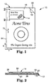
- FIGS. 1 and 2 illustrate a promotional assembly 10 that includes an advertising piece 12 and a repositionable sheet 14.
- the advertising piece shown has a plurality of pages: a first top page or cover 16, a second or opposite inside page 18, a third or juxtapositioned inside page 20, and a fourth or rear page 22.
- the pages 16, 18, 20 and 22 can be printed on a single sheet which is folded at 24. Additional pages can be provided by, for example, increasing the number of folded sheets.
- the advertising piece 12 may comprise a single sheet or multiple sheets bound in some other manner (e.g., stapled or adhered together) or may even comprise a book, letter, product package, etc.
- it is only essential that the article receiving the repositionable sheet have a face (such as cover 16) suitable for the adherence of a repositionable sheet thereon.
- the term "repositionable” means the sheet 14 can be adhered to and removed from a clean solid surface at least two times without substantially losing tack. Preferably, the sheet can be adhered to and removed from a clean solid surface at least ten and, more preferably, at least twenty times without substantially losing tack.
- the repositionable sheet 14 is secured directly to the advertising piece by RPSA 26 (FIG. 2), coated at least partially on a first or back side 28 of the sheet 14.
- the repositionable sheet 14 has a second or top side 30 onto which information can be printed (e.g., which corresponds to or further emphasizes information printed on the advertising piece 12). As illustrated, the repositionable sheet 14 can have the name and phone number of an advertiser printed on the top side 30 of the sheet 14.
- a repositionable sheet suitable for this application can be a repositionable note of the type sold by Minnesota Mining and Manufacturing Company of St. Paul, Minnesota under the trade designation "Post-It.”
- Each repositionable note includes a sheet of paper that has an adhesive partially coated on one side thereof.
- the sheet of paper is typically an unsaturated paper, which is paper that is not impregnated with a resin.
- the adhesive is coated as a narrow band adjacent one edge of the sheet, although other embodiments are possible, such as where only corners or other portions (or even all) of the back side of the sheet are coated with RPSA.
- the paper may be coated with a primer to enhance the anchorage of the adhesive to the substrate.
- the amount of adhesive on the back side of the repositionable sheet must be sufficient to enable the sheet to adhere to a clean surface.
- ARPSA typically comprises polymeric microspheres having an average diameter of at least about one micrometer.
- the microspheres are inherently tacky and typically comprise at least about 70 parts by weight of an alkyl acrylate or alkyl methacrylate ester.
- a majority of the microspheres may contain interior voids, typically, at least about 10 percent of the diameter of the microsphere.
- RPSAs are tacky to the touch and typically demonstrate a peel adhesion of approximately 10 to 300 gram/centimeters (g/cm), more typically approximately 50 to 250 g/cm, and even more typically about 70 to 100 g/cm. Peel adhesion can be determined according to the test outlined in U.S. Patent 5,045,569.
- a RPSA can be applied to a sheet using known methods including making a suspension of the microspheres and applying that suspension to the sheet by conventional coating techniques such as knife coating or Meyer bar coating or use of an extrusion dye ( see U.S. Patent 5,045,569 at column 7, lines 40-50).
- repositionable adhesive coatings may include: printing a fine pattern of adhesive dots; selective detackification of an adhesive layer; and incorporating nontacky microspheres in an adhesive matrix.
- Other useful adhesives include high peel adhesives that may permanently attach a note. Examples of such adhesives include rubber resin and acrylic adhesives.
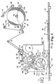
- FIG. 3 illustrates an apparatus 40 useful for forming and applying repositionable sheets in registry onto a series of moving articles.
- the apparatus 40 includes an article conveyor path and a repositionable sheet transport path. The two paths converge at an application station (indicated generally as at 42) where a cut repositionable sheet is adhered to each article.
- the apparatus 40 includes a base unit 44 which serves to hold the supply of articles (e.g., advertising pieces 12) for processing.
- the base unit 44 includes an article conveyor 46 for sequentially transporting articles from one end of the base unit to the other, and in particular, across application station 42.
- Article conveyor 46 may include a belt conveyor 46a, chain link conveyor 46b, or other suitable conveyance devices (e.g., rollers, etc.) which may further include article spaced alignment tabs 47 for engaging a leading end of an article 12 and positively positioning it relative to the application station 42.
- the article conveyor 46 is driven by a conveyor drive motor 48 to move articles in direction of arrow 49 in FIG. 3. After processing at the application station 42, the articles are further conveyed to a receiving area (not shown) where they are collected for further processing and/or distribution.
- a base unit for this purpose which includes a conveyor for materials like advertising pieces, flyers or magazines, is the Kirk-Rudy Model 215 labeling base, available from Kirk-Rudy, Inc. of Kennesaw, Georgia.
- An optical sensor 51 is supported by the base unit 44 over the process path followed by the articles 12.
- the optical sensor 51 generates a signal when it detects the presence of an article 12 thereunder.
- the signal is provided to a process controller 86 (see FIG. 4) for use in controlling operation of the apparatus 40, as discussed subsequently.
- the optical sensor is a photosensor such as an Eaton sensor; Cutler Hammer, Comet Series, Series A2, 95015.
- the base unit 44 also serves to support a sheet applicator head 50, and a supply of linerless repositionable sheeting 52 which is elongated in a longitudinal orientation.
- the sheeting 52 is provided in a roll 53 which is rotatably mounted on a spindle 54 which, in turn, is supported by suitable means on the base unit 44 (alternatively, the spindle 54 may be supported by the head 50).
- the repositionable sheeting 52 is referred to as "elongated” because it is not yet cut into a number of discrete repositionable sheets, and thus the length ofthe elongated repositionable sheeting, as its name implies, is much greater than its width.
- linear is used herein to mean an adhesive on a sheet is exposed from the time the sheet is supplied with the adhesive secured thereto (e.g., comes off a supply roll) to an apparatus for adhering the sheet to a substrate and the time the repositionable sheet is adhered to that substrate.
- a repositionable sheet is not considered to be linerless when a liner covering the adhesive is removed to expose the adhesive just prior to adhering the sheet to a substrate.
- the elongated, linerless repositionable sheeting 52 is positioned on the roll 53 with its back or adhesive bearing side 55a facing the center of the roll 53 and its top or information bearing side 55b facing the periphery of the roll 53.
- the repositionable cut sheets 14 are cut from the sheeting 52.
- the back (adhesive-bearing) side 28 of the sheet 14 corresponds to the back side 55a of the sheeting
- the top side 30 of the sheet 14 corresponds to the top side 55b of the sheeting 52.
- the top side 55b of the sheeting 52 may have a low adhesion backsize coating thereon, to facilitate unwinding of the sheeting 52 from the roll 53.
- Such a low-adhesion backsize coating may include silicone polymers, fluorocarbon polymers, urethanes, acrylates, and chrome complexes.
- Unwind apparatus 56 includes a drive motor 57 which is operably coupled (e.g., by a belt drive) to rotate rubber drive roller 58, which in turn is maintained in surface contact with the circumference of the roll 53 of sheeting 52.
- the drive motor 57 and drive roll 58 are pivotally supported above the roll 53 by a drive support arm 59, so that as the sheeting 52 is unwound from the roll 53 and the circumference of the roll 53 becomes smaller, the drive roller 58 is maintained (by gravity and the weight of the drive motor 57, drive roller 58 and support arm 59) in surface drive contact with the roll 53, as seen in FIG. 3.
- the sheeting 52 As the sheeting 52 is unwound from the roll 53, it first passes over an idler roller 60 and then a dancer roller 61. Both rollers 60 and 61 are supported by the base unit 44, but the idler roller 60 is held stationary while the dancer roller 61 is mounted for pivotal movement about the axis of the spindle 54 by a first portion 62a of a dancer support arm 62.
- a counterweight 63 is supported by an opposed second portion 62b of the dancer support arm 62, as seen in FIG. 3. The weight of the counterweight 63, through the dancer support arm 62, urges the dancer roller 61 upwardly.
- An optical sensor 64 (supported on the base unit 44) generates a signal when it detects that the dancer support arm 62 has pivoted upwardly to a predetermined position. That signal is provided to the process controller 86, which in turn activates the drive motor 57 to cause rotation of the roll 53 and release additional sheeting 52 from the roll 53. As sheeting 52 is unwound from the roll 53, sheeting-applied tension on the dancer roller 61 will diminish, and the dancer support arm 62 will pivot downwardly and out of its signal generating position. The lack of a signal from the optical sensor 64 will be noted by the controller 86 and the drive motor 57 deactivated.
- the optical sensor 64 is a photosensor such as the Banner Mini-Beam SM312DQG sensor, available from Banner Engineering Corporation, Minneapolis, Minnesota, and the drive motor 57 is a Balder Industrial motor identified as catalog No. GP7401, available from Balder Electric Co., Fort Smith, Arkansas.
- the elongated, linerless repositionable sheeting 52 travels through a series of rollers which define a process path before reaching a cut station 65, where the elongated sheet 52 is cut transverse to its advance direction in the process path to provide a discrete, cut repositionable sheet 14 of desired length.
- cut means the sheet has been completely severed from a larger sheeting.
- the sheet applicator head 50 is a Kirk-Rudy linerless pressure sensitive stamp affixer which has been modified for use in applying linerless repositionable sheeting.
- the specific stamp affixer used for this purpose is KR-221-223 LSA stamp head, available from Kirk-Rudy, Inc. of Kennesaw, Georgia, which was designed to apply roll form linerless pressure sensitive postage stamps.
- the head 50 is supported by suitable means over the base unit 44.
- suitable means may include a transfer drive shaft 66, which is rotatably driven by the motor 48 on the base unit 44, as well as by support bar 68.
- the shaft 66 and bar 68 are supported by the base unit 44, and extend through or under the head 50.
- the head 50 is supported over the base unit 44 in this manner to allow its transverse alignment relative to the advancing articles therebelow, and thus allow selective placement of a sheet 14 across the face of the article 12 (as illustrated by double arrows 70 (in axis x) in FIG. 1).
- the elongated, linerless repositionable sheeting 52 is unwound from roll 53 through the process path by passing over the idler roller 60 and dancer roller 61 as discussed, and then over a series of idler rollers 72, 74 and 76.
- the process path is then defined by a back-up plate 78 and idler roller 80.
- the rollers 72, 74, 76 and 80 and back-up plate 78 are all supported on the head 50.
- a sheet uncurling bar (or bars) may also be disposed in the process path to remove tendencies of the sheeting 52 to curl after cut into individual cut sheets 14.
- the rollers 76 and 80 are positioned so that the sheeting 53 is urged against the back-up plate 78 disposed therebetween (see FIGS. 1 and 5).
- a hold-down brush 82 supported by the head 50 is disposed adjacent the back-up plate 78 and against the back side 55a ofthe sheeting 52 to further urge the top side 55b of the sheeting 52 against the back-up plate 78 as it passes thereover.
- the back-up plate 78 has a generally planar face 83 (FIG. 5) over which the sheeting 52 traverses.
- An optical sensor 84 is also supported by the head 50, and is disposed immediately downstream of the brush 82 along the process path, and opposite the face 83 of the back-up plate 78. The sheeting 52 thus passes between the back-up plate 78 and optical sensor 84.
- a series of equally spaced (and preferably identically shaped) eyemarks 85 are printed on the back side 55a of the sheeting 52 (as seen in FIG. 5).
- the optical sensor 84 is positioned to illuminate and detect the presence of the eyemarks 85 as the sheeting 52 is advanced along the process path. Upon detecting an eyemark 85, the sensor 84 provides a signal to a process controller 86 (FIG. 4).
- the brush 82 serves to hold the sheeting 52 in alignment on the back-up plate 78, and reduce possible flutter or canting of the sheeting 52, thereby permitting precise readings of the eyemarks 85 by the optical sensor 84 as the sheeting 52 is advanced along the process path.
- the optical sensor 84 is a photoelectric sensor such as a BANNER Mini-Beam SM312CVGQD sensor, available from Banner Engineering Corporation, Minneapolis, Minnesota.
- the drive roller 90 is preferably formed from aluminum, and engages the back or adhesive bearing side 55a of the sheeting 52, and has its circumferential surface formed in a manner (such as grooves 92) so that it presents sufficient surface to engage and advance sheeting 52 along the process path, but does not present such a surface that allows the adhesive 26 to become adhered thereto instead of continuing to allow the sheeting 52 to be advanced. As best shown in FIG.
- the elongated, linerless repositionable sheeting 52 is firmly pressed against drive roller 90 by one or more pinch rollers 94, so that sheeting 52 does not slip when the drive roller 90 advances the elongated, linerless repositionable sheeting 52. It is important that the elongated, linerless repositionable sheeting 52 not slip when the drive roller 90 advances, otherwise the sheeting 52 would not be cut to the proper size and some of the information printed on the top side 55b thereof may be severed from the cut repositionable sheet 14.
- the pinch rollers 94 do not urge portions of the sheeting 52 bearing adhesive 26 against the drive roller 90.
- a sheet guide 96 is also provided adjacent the drive roller 90 to aid in feeding the sheeting 52 along the process path and into the cut station 65.
- the sheet guide 96 has a curved face 98 which is radially spaced from the circumference of the drive roller 90 a distance sufficient to permit sheeting 52 to pass therebetween, as seen in FIG. 3.
- the pinch rollers 94 and sheet guide 96 are also supported by the head 50.
- the drive roller 90 is driven by a stepper motor 100 mounted on the head 50, preferably a synchronous stepping motor of the type available from Superior Electric, Bristol, Connecticut under the trade designation "SLO-SYN," model M093-FD-8014.
- Activation of the stepper motor 100 is in turn controlled by signals provided by the process controller 86. More specifically, the stepper motor 100 is activated by a signal from a proximity switch 101 (FIG. 4) which serves to coordinate the advance of articles 12 and sheeting 52.
- the proximity switch 101 detects rotation of a shaft (not shown) on the head 50 which is rotatably driven via the transfer drive shaft 66 (which is, in turn, driven by the base unit conveyor motor 57).
- the proximity switch 101 is preset to detect a rotation position of the shaft that then coordinates activation of the stepper motor 100 with the advance of articles 52 into the application station 42.
- the process controller 86 also signals the supply unwind motor 57 to permit a like amount of sheeting 52 to be dispensed from the roll 53 as it is advanced by the drive roller 90.
- the stepper motor 100 is deactivated by the process controller 86 when an eyemark 85 is detected by the photosensor 84.
- the process path enters the cut station 65, where the elongated, linerless repositionable sheeting 52 is cut along a line transverse to the direction of its advancement into a plurality of sequentially formed, discrete repositionable sheets 14.
- each cut may define the trailing edge of the immediately cut sheet and the leading edge of the next cut sheet.
- the linerless repositionable sheeting is used to form cut repositionable sheets, and the generation of excess waste is avoided.
- no elongated sheeting remains which exits the apparatus after the sheeting has been cut, and thus no take-up reel is necessary to gather residual or unused elongated sheeting or liner.
- a rotary knife 102 is mounted on the head 50.
- the rotary knife 102 has a cutting edge 104 which acts against opposed anvil 106 to sever the sheeting 52 disposed therebetween.
- the anvil 106 is supported by the head 50 and serves to support the sheeting 52 as it exits the drive roller 90 and sheet guide 96.
- Each cut by the knife 102 is made after advancement of the sheeting 52 a desired length to define a repositionable sheet 14.
- the blade 104 also passes across a blade cleaning roll 108, which serves to wipe the blade 104 clean of any adhesive or sheeting material carried thereby.
- the blade cleaning roll 108 is preferably formed from felt or some other suitable material for wiping the blade 104 as it passes.
- Drive roller 90 is selectively rotated to advance the elongated, linerless repositionable sheeting 52 through the cut station 65 on the process path defined on the head 50.
- the blade 104 of the rotary knife 102 is rotated past the anvil 106 to sever a cut sheet 14 from the leading portion of the elongated, linerless repositionable sheeting 52.
- a rotary transfer assembly 110 moves into place under the cut sheet 14.
- Rotary transfer assembly has a transfer head 112 which is aligned to rotate about a central drive shaft 114.
- the transfer head 112 has an arc-shaped platen face 116 which is rotated through the cut station 65 and transfer station 42 in direction of arrow 117.
- the transfer head 112 As the transfer head 112 passes through the cut station 65, its platen face 116 engages the nonadhesive side 30 of the cut sheet 14.
- the transfer head 112 has a vacuum chamber (not shown) therein, which is coupled to one or more vacuum pickup ports 118 on the platen face 116.
- a vacuum manifold 122 is also coupled to a chamber in the transfer head 112 adjacent the shaft 114, and the manifold 122 is further coupled to a vacuum source by suitable means, such as tubing 124.
- a vacuum is drawn through the tubing and manifold on a constant basis, but the chamber and thus vacuum pickup ports 118 are shielded during rotation of the transfer head 112 so that a negative pressure is drawn through vacuum pickup ports 118 only when desired (from the time cut sheet 14 is picked up at the cut station 65 until it is laid down at the application station 42).
- a vacuum is drawn through vacuum pickup ports 118 to pull sheet 14 down against the platen face 116 and secure it thereto (see FIG. 7).
- a spring steel sheet guide 126 is aligned on the head 50 and adjacent the path traversed by the platen face 116 of the transfer head 112 to further prevent the dislodgement of the cut sheet 14 from the platen head 116.
- the suction through vacuum pickup ports 118 is cut off to release the cut sheet 14 from the transfer head 112.
- the adhesive 26 on the back side 28 of the cut sheet 14 adheres to the cover 16 of the article 12 to engage it thereto.
- the article 12 continues to advance (by operation of conveyor 46) through the application station 42, and the transfer head 112 continues to rotate, thereby pressing or wiping the cut sheet 14 against the cover of the article 12 and further enhancing the adhesion of adhesive 26 therebetween.
- a driven back-up roll 132 is supported by the base unit 44 to further define a nip through which the cut sheet 14 and article 12 must pass in the application station 42 to facilitate this bonding process.
- the transfer head 112 and back-up roll 132 are driven by the base unit conveyor motor 48.
- the operative coupling of the drive shaft 114 for the transfer head 112 (on the head 50) and the conveyor motor 48 (on the base unit 44) is accomplished via the transfer drive shaft 66 mounted between the base unit 44 and head 50.
- the transfer head 112 After depositing a cut sheet 14 in the application station, the transfer head 112 continues to rotate (in direction of arrow 117) back to the cut station 65 and into position to accept another cut sheet 14 for pickup, transfer and application to another article 12.
- the transfer head 112 preferably has two platen faces 116, opposed by 180°, so that for each rotation of the transfer head 112, two cut sheets 14 are moved from the cut station 65 to the application station 42.
- the sheet 14 is longer than the platen face 116 (trailing edge 121 of platen face 116 is overlapped by trailing edge 131 of sheet 14).
- the sheet 14 is released by the transfer head 112 just prior to entering the application station 42 so that as the transfer head 112 rotates, it wipes the entire sheet 14, out to its trailing edge 131. This may also be accomplished by setting the conveyor 46 for overtravel relative to the moving transfer head 112.
- the rotary knife 102 is also driven by the base unit conveyor motor 48. Again, the operative coupling ofthe rotary knife (on the head 50) and the conveyor motor 48 (on the base unit 44) is accomplished via the transfer drive shaft 66 mounted between the base unit 44 and head 50.
- a mechanical clutch (not shown) is disposed between the transfer drive shaft 44 and the rotary knife. That clutch is engaged by the process controller 86 when the photosensor 51 detects an advancing article 12 to rotate the knife 102.
- a knife rotation sensor 134 (FIG.
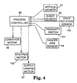
- the apparatus is controlled by a process controller 86, based upon preset inputs (e.g., desired length of cut sheet 14, desired registration position of sheet applied on article 12 (both in the x-axis and the y-axis, as seen in FIG. 1), as well as in-process signals from optical sensors 51 and 84, and the knife rotation sensor 134 and the proximity switch 101.
- the process controller 86 thus activates the motors 48, 57 and 100, dependent upon the preset conditions and in-process signals to continually, uniformly and sequentially apply each cut sheet 14 in the same relative position on an article 12.
- this apparatus it is possible to create, for example, up to 15,000 identical promotional assemblies 10 per hour (with each cut sheet 14 having a length of 76.2 mm (3 inches)).
- the apparatus of the present invention performs the following steps to adhere a cut repositionable sheet 14 to an advertising piece 12.
- the base unit conveyor motor 48 is activated to initiate conveyance of articles 12 sequentially through the application station 42.
- sensor 51 detects an approaching advertising piece 12, it relays a signal to process controller 86, which in turn activates the rotary knife 102 clutch so that the knife 102 rotates for cutting.
- the proximity switch 101 detects rotation driven by the base unit conveyor motor 44 and activates the motor 100 to rotate drive roller 90 to advance the elongated, repositionable sheeting 52.
- the dancer support arm 62 will move upwardly to be detected by optical sensor 64.
- the sensor 64 will relay a signal to the process controller 86, which in turn activate the drive motor 57 (as necessary) to facilitate the unwinding of sheeting 52.
- the supply unwind apparatus 56 thus serves to attenuate the otherwise incremental advance of sheeting 52 from the roll 53.
- the sensor 84 detects an eyemark 85 on the back side 55a of the elongated repositionable sheeting 52.
- Sensor 84 relays a signal to the process controller 86, which in turn deactivates the motor 100 to stop the rotation of drive roller 90 and advance of the sheeting 52 along the process path.
- Rotation of the rotary knife 102 was momentarily stopped by knife rotation sensor 134 to permit the desired length of sheeting 52 to pass by the knife 102 prior to its severing the leading portion of the elongated repositionable sheeting 52 into a cut sheet 14.
- the transfer head 112 of the rotary transfer assembly 110 is rotated to a position below the just cut sheet 14, and a negative pressure drawn through vacuum ports 118 to adhere the cut sheet 14 to the platen face 116 of the transfer head 112.
- the transfer head 112 continues to rotate, approaching the application station 42.
- the negative pressure is released, thereby releasing the cut sheet 14 from the platen face 116.
- the adhesive 26 on the cut sheet 14 engages the article 12 as it moves through the application station 42.
- the transfer head 112 continues to rotate and the platen face 116 presses or wipes the cut sheet 14 onto the article 12, backed up in this position by the driven back-up roller 132.
- the advertising piece 12 and sheet 14 adhered thereon continue to advance in the direction of arrow 49 (via conveyor 46) to exit the apparatus. This process is repeated over again to register and adhere each cut repositionable sheet 14 to an advertising piece 12.
- the cut sheet 14 adheres via adhesive 26 to the article 12, but as mentioned above, the adhesive is RPSA and thus the cut sheet 14 may be removed and re-adhered to the article 12, or removed for placement on an alternative clean surface (e.g., desk, refrigerator or for use, for example, as a coupon).
- the elongated, linerless repositionable sheeting can be formed from a bond paper, preferably having a basic weight of 15 to 25 pounds. Such paper is provided in elongated, roll form, and then cut into separate note sheets by the inventive apparatus. Typical properties of such sheets include a caliper of 0.002 to 0.009 inches (51 to 229 microns), and an adhesive area covering a portion of one surface of the sheet.
- the adhesive may cover from 10 percent to 90 percent of the surface, preferably between 20 percent to 75 percent, and more preferably between 15 to 50 percent.
- the adhesive may be coated as a continuous stripe along an edge or be coated in a discontinuous pattern, such as lines of adhesive dots.
- Each sheet preferably bears a strip of RPSA along one edge thereof on its back side, while on its top side, each sheet bears preprinted indicia or images. Preferably, only a minor portion of the back side of the cut sheet may bear RPSA.
- the top (nonadhesive bearing) side of the sheeting may be coated with a release layer to facilitate the unwinding of the roll.
- the indicia or image borne by the sheets is preferably the same for each cut sheet.
- the elongated sheeting material (prior to cutting) bears a repeating pattern of the same indicia or image along its length. The pattern repeats in equal length segments, with each segment designed to be cut into a separate cut sheet.
- the sheeting may also contain a line or path of weakness (such as perforations) generally parallel to the adhesive so that a portion of the sheet (without adhesive) could be separated from that portion ofthe sheet bearing adhesive.
- a line or path of weakness such as perforations
- the nonadhesive portion can be torn away from the adhesive portion (which may remain on the article). This embodiment may be particularly useful for coupons or return mail postcards.
- the eyemarks printed on the back of the sheeting are used to define the cut length and control parameters for the apparatus.
- the eyemarks are positioned along what would be the cut line between adjacent cut sheets on the elongated sheeting, so that after cutting, half of each eyemark is borne by subsequently cut adjacent sheets.
- a cut note sheet will be cut by the inventive apparatus to a size of less than 100 square inches (645 cm 2 ). More typically, cut sheets have a size in the range of 1 to 30 square inches (6 to 194 cm 2 ), and even more typically in the range of 2.5 to 25 square inches (16 to 161 cm 2 ). Cut repositionable sheets frequently measure about 3 inches by about 5 inches (7 by 13 cm) or about 4 inches by about 6 inches (10 by 15 cm). Another common size is about 1.5 inches by about 2 inches (3 cm by 5 cm). Using the present apparatus, typical cut lengths for each cut sheet range from 1 to 6 inches.
- rolls of sheeting material up to 508 mm (20 inches) in diameter can be accommodated (depending upon the thickness of the sheeting material) and may provide a supply of sheeting material having a generated length of about 2300 lineal yards (about 2100 meters).
- the rollers 60, 61, 72, 74, 76, 80 and 90, plate 78 and applicator head 112 have widths (transverse to the process path) of about 82.55 mm (3.25 inches).
- the optical sensor 84 which is employed to detect the eyemarks 85 is a sensor suitable for detecting changes in opacity.
- the eyemark may be darker or lighter than the sheeting color, so long as the change in contrast between the eyemark and sheeting substrate color is sufficient to generate a detection signal by the optical sensor 84.
- the eyemark will be a mark made with black ink, such as illustrated in FIG. 5.
- the sheet substrate is an opaque paper. Printing is required on both sides of the sheeting to deposit the eyemarks on the back side thereof and the preprinted indicia or image on the top side thereof.
- the present invention is also applicable to other sheet structures.
- the sheeting material may be conventional bond or clay-coated paper, carbonless paper, a polymeric sheet material or even a metallic foil.
- transparent or translucent substrate materials i.e., light-transmissive
- translucent substrate materials such as those used for repositionable tape flags sold by Minnesota Mining and Manufacturing Company of St. Paul, Minnesota under the trade designation "Post-It," are also possible sheeting materials.
- a tape flag is a discrete, flexible sheet which has a first major side and a second major side. On its first major side (back side), RPSA is provided adjacent a first end of the elongated sheet (typically on at least half or a major portion of the back side of the sheet). Adjacent its second end, the tape flag is provided with a visible indicator of contrasting color. This may be an inked color covering a tab portion of the second end of the sheet (on either side thereof) or a preprinted image or message (such as "Sign Here"). Tape flags are typically used as temporary indicators of pages in books or documents, or portions of documents to be noted by a reader.
- That portion of the tape flag which bears RPSA is sufficiently transparent when adhered to a page so that underlying text on the page may be perceived and read.
- an indicator image (such as an arrow) is printed on this first transparent portion of the tape flag to enhance its use as an indicator of sections of a page to which it is adhered.
- the preprinted indicia or image thereon itself can serve as an eyemark for tape flags dispensed and applied using the apparatus of the present invention. This is more fully described in connection with FIGS. 8-11 and FIG. 3.
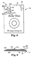
- FIGS. 8 and 9 illustrate a promotional assembly 10a that includes an advertising piece 12 and a repositionable sheet 214.
- the advertising piece is, for illustrative purposes, the same as that shown and described previously, and again can be any article suitable for mounting a repositionable sheet thereon.
- repositionable sheet 214 is again secured directly to the advertising piece 12 by RPSA 226 coated partially on the first or back side 228 of the sheet 214 (with the RPSA 226 preferably coated over 25 to 75 percent of the back side 228).
- Repositionable sheet 214 has a second or top side 232. Ink of a contrasting color or a preprinted message may be printed on either side of the sheet 214 (if printed on the first side 228, the RPSA is applied over the printing).
- Each sheet 214 (as a tape flag) is typically elongated (with a length ranging from 25.4 to 76.2 mm (1 to 3 inches), with a first end 231 and a second end 233.
- the substrate polymer material for the sheet 214 is flexible and generally transparent, as is the RPSA (disposed adjacent the first end 231).
- RPSA disposed adjacent the first end 231.
- the sheet 214 will bear a visually distinctive color ink in a second substantially opaque section 237, which is useful in calling attention to portions of the article 12 (and/or the second section 237 may include a printed message 238).
- the sheet 214 may also include an arrow or other indicator 239 printed on the first section 235 thereof.
- the tape flag sheet is formed from cellulose acetate, such as disclosed in Miles et al. U.S. Patent 4,907,825.
- the tape flag sheet is formed from biaxially oriented polyethylene terephthalate (PET). In either case, the tape flag sheet may have a thickness ranging from .0254 mm (.001 inch) to .127 mm (.005 inch), and more preferably .0508 mm (.002 inch).
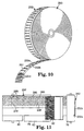
- Sheeting 252 is provided in the form of a roll 253, as illustrated in FIG. 10.
- the sheeting 252 has a back adhesive bearing side 255a facing the center of the roll 253 (which corresponds to back side 228 of sheet 214), and a top or information readable side 255b towards the periphery of the roll 253 (which corresponds to top side 230 of sheet 214).
- the sheeting 252 traverses the process path through apparatus 40 in the same manner as previously described, with its adhesive side 255a facing drive roll 90, and its nonadhesive side 255b ultimately engaged by transfer head 112.
- the arrows 239 are repeatedly printed along the length of the sheeting 252, one for each cut sheet 214 to be severed therefrom. Because a portion of the sheeting 252 is generally transparent (portion 261 (FIG. 10), corresponding to first section 235 of cut tape flag sheet 214), the arrows 239 are visible on either side of the sheet (regardless of which side the arrows 239 are printed on), and thus can serve as the eyemarks 285 for the tape flag sheeting 252. Other contrasting patterns or indicator marks printed on the sheeting 252 can also serve as the registration means (eyemarks) so long as they are sufficiently detectable.
- FIG. 11 A portion of the sheeting 252 is shown in FIG. 11 as disposed for detection of eyemarks 285 by optical sensor 84.
- the tape flag sheeting 252 extends between rollers 76 and 80, and across the face 83 of back-up plate 78.
- the brush 82 aids in holding the sheeting 252 flat against the back-up plate 78 for eyemark 285 detection by optical sensor 84 disposed thereabove (see FIG. 3).
- the arrows 239 present a sufficient contrast to the transparent portion 261 of the sheeting 252 to permit detection and signal generation by optical sensor 84.
- the signal generated by optical sensor 84 is provided to the process controller 86, and again serves to register the tape flag sheeting for advancement and cutting into discrete cut sheets 214, and ultimately for application onto the articles 12.
- Conventional tape flags are relatively narrow, and may range in width from 10.16 mm (0.4 inch) to 50.8 mm (2 inches) and more preferably, about 25.4 mm (1 inch).
- 25.4 mm (one inch) wide (or long as viewed in direction of advancement through the process path) cut sheets are possible.
- some of the vacuum pickup ports 118 may be covered (i.e., masked by the application of adhesive tape) so that a vacuum is drawn only through those ports that arc presented to the cut sheet at the cutting station (e.g., in FIG. 7, port 118a for cut sheet 214).
- Relatively long lengths of sheeting may be processed into tape flags individually disposed on articles. For example, a roll of tape flag sheeting up to 355.6 mm (14 inches) in diameter can be processed, which would represent a generated length of about 1800 yards (1645 meters).
- One fundamental objective of the inventive method and apparatus is the formation of a multitude of identically registered promotional articles, where the cut sheet is adhered to the article in precisely the same location every time.
- the system sensing and control means described are thus provided to apply the cut sheet in register to the article (e.g., a magazine signature).
- the degree of registration is controlled using register marks or eyemarks.
- the present inventive method and apparatus can provide a predetermined degree of registration between the cut sheet and article of +/- 25.4 mm (one inch) in any direction (x and y, as noted in FIG.
- the degree of registration attained is +/- 8.38 mm (0.33 inch) in any direction (a tolerance known as "loose register”); more preferably, the degree of registration attained is +/- 3.175 mm (0.125 inch) in any direction; and most preferably, the degree of registration is +/- .794 mm (0.03125 inch) in any direction (a tolerance known as "lap register”).
- loose register a tolerance known as "loose register”
- the degree of registration attained is +/- 3.175 mm (0.125 inch) in any direction
- the degree of registration is +/- .794 mm (0.03125 inch) in any direction (a tolerance known as "lap register”).
- Registration is a term used in the printing industry relating to the placement of ink or other converting between different stations on the printer or different pieces of equipment.
- Register marks or eyemarks are indicia (usually separate from the remaining printed graphics of a printed piece) that are typically located along an edge of the printed piece. Such marks may be "crosshairs” (indicia printed as two perpendicular, straight lines intersecting at their midpoints) or may be printed as a simple rectangle. Typically, these marks are cut off when the printed product is finished.
- the marks for the present invention may be separately printed on the sheeting (e.g., as in FIG. 5) or may be defined as a portion of the indicia or image printed on the sheeting (e.g., as in FIGS. 10 and 11).
- This latter approach eliminates printing on both sides of the sheeting (such as when the sheeting is transparent) and minimizes waste of the sheeting material (since no trimming is required), thus improving the overall efficiency of the process and its material usage.
- registration means such as visually detectable eyemarks and detecting means therefor such as photosensors
- alternative registration and detecting systems are possible.
- the registration means can be visible, tactile, olfactory, auditory or tasteable, as disclosed in U.S. Patent 5,382,055.
Description
Claims (19)
- A roll (53) of sheet material (52) which is elongated logitudinally, having first and second opposed sheet sufaces, and first and second opposed side edges, the roll of sheet material comprising:a pressure sensitive adhesive extending in a predetermined pattern on only a first adhesive portion of the first surface of the sheet material (52), adjacent the first side edge thereof;the sheet material (52), adjacent its first side edge and including the first adhesive portion, being formed from a material that is sufficiently transparent when adhered to a substrate that underlying images on the substrate are substantially visible through the sheeting material (52); anda plurality of longitudinally spaced and detectable images disposed in predetermined locations on the first adhesive portion of the sheet material (52).
- The roll (53) of sheet material (52) of claim 1 wherein the first adhesive portion is defined as approximately half of the first surface of the sheet material (52).
- The roll (53) of sheet material (52) of claim 1 wherein the sheet material (52) has a second tab portion adjacent the second side edge thereof, and further comprising:
a plurality of longitudinally spaced and visible tab images disposed in predetermined locations on the second portion of the sheet material (52). - The roll (53) of sheet material (52) of claim 3 wherein the images on the first adhesive portion of the sheet material (52) are equally spaced longitudinally, and wherein the tab images on the second portion of the sheet material (52) are equally spaced longitudinally.
- The roll (53) of sheet material (52) of claim 1 wherein the sheet material (52) has a second tab portion adjacent the second side edge thereof, and further comprising:
a coating of opaque material on the second tab portion of the sheet material (52). - The roll (53) of sheet material (52) of claim 1 wherein the adhesive is a repositionable pressure sensitive adhesive.
- The roll (53) of sheet material (52) of claim 1, wherein the plurality of images form a repeating indicia pattern which is visible on either side of the sheet material (52) for use during processing as an indicator to facilitate cutting apart discrete sheeting segments, of equal cut length, with each segment bearing a repeated pattern of the indicia printed thereon.
- The roll (53) of sheet material (52) of claim 7 wherein the pressure sensitive adhesive is reposifiorable pressure sensitive adhesive disposed to cover a majority of the first surfaceof each discrete cut sheeting segment.
- The roll (53) of sheet material (52) of claim 7 wherein the pressure sensitive adhesive and indicia pattern are adjacent the first side edge, and further comprising:
a coating of opaque material on one side of the sheeting adjacent the second side edge thereof. - A method of sequentially adhering linerless repositionable sheets (14) to a corresponding sequence of articles (12), the method comprising:(a) supplying an elongated linerless sheeting (52) in wound roll form, the sheeting (52) having a first major side (55a) and an opposite second major side (55b), with pressure sensitive adhesive coating partially disposed on the first side (55a) of the sheeting (52) and with the second side (55b) thereof being free of adhesive;(b) advancing a leading portion of the elongated linerless sheeting (52) along a process path until it reaches a cut station (65),(c) laterally cutting the leading portion of the linerless sheeting (52) to define a first cut sheet (14) having a first lead edge and a second trailing edge;(d) aligning a vacuum platen having an arcuate circumferential surface into engagement with at least a portion of the second side of the first cut sheet (14) adjacent the first lead edge thereof:(e) forming a negative pressure on a portion of the arcuate circumferential surface of the vacuum platen to affix the first cut sheet (14) in the cut station (65) thereto;(f) advancing a first article (12) having a face into an applicator station (42) adjacent the vacuum platen;(g) moving the vacuum platen to carry the first cut sheet (14) from the cut station (65) to the applicator station (42) whereby the first cut sheet (14) is aligned for placement on the face of the first article (12);(h) relieving the negative pressure on the arcuate circumferential surface to release the first cut sheet (14) from the vacuum platen;(i) moving the vacuum platen across the face of the article (12) so that the pressure sensitive adhesive on the first side of the first cut sheet (14) is pressed against the face of the article to bond the first cut sheet (14) to the face of the article (12),(j) repearing steps (b) and (c) to define a second cut sheet from the elongated linerless sheeting (52),(k) repeating steps (d) and (e) with the vacuum platen relative to the second cut sheet;(l) advancing a second article having a face into the applicator station (42) adjacent the vacuum platen; and(m) repeating steps (g), (h) and (i) with the second cut sheet to align, release from the vacuum platen and then press the second cut sheet against the face of the second article by the arcuate circumferential surface of the vacuum platen.
- The method of claim 10 wherein the cutting step includes rotating a laterally disposed rotary knife (102) across the process path at the cut station (65).
- The method of claim 10 wherein the elongated linerless sheeting (52) has, on its first side, a series of longirudinally disposed, equally spaced visual indicators (85), and wherein the method further comprises the step of
detecting each visual indicator (85) on the sheeting (52) as it is advanced along the process path to a generate a signal used for process control purposes. - The method of claim 10 wherein at least that portion of the elongated linerless sheeting (52) coated with pressure sensitive adhesive is light transmissive.
- The method of claim 10 wherein the cut sheets (14) are adhered to the articles (12) to form an adhered sheet assembly at a rate of up to 30,000 adhered sheet assemblies per hour.
- The method of claim 10 wherein the advancing step includes:rotating a drive roll (58) in engagement with the elongated linerless sheeting (52) along the process path; anddriving the unwinding of the supply roll (53) of elongated linerless sheeting (52) to advance the sheeting (52) onto the process path in controlled coordination with the rotation of the drive roll (58).
- The method of claim 10 wherein the adhesive is a repositionable pressure sensitive adhesive.
- A method for affixing a plurality of sheets to a plurality of moving articles (12) comprises:providing a roll (53) of sheet material (52);sequentially cutting the sheet material (52) from the roll (53) into identically sized sections, with each section defining one sheet (14) and wherein each sheet (14) has repositionable pressure sensitive adhesive on at least a back portion (55a) thereof,providing a supply of articles (12), each article (12) having a face presented for adhesion of a corresponding sheet (14) thereto;sequentially applying the sheets (14) to the articles (12) at a rate of over 3,000 per hour, andaligning each sheet (14) on the face of its respective article (12) to within 3.175 mm (0.125 inch) of a desired location in any planar coordinate.
- The method of claim 17 wherein each cut sheet (14) is aligned on each article (12) to within .794 mm (0.03125 inch) of a desired location in any planar coordinate on the face of the article (12).
- The method of claim 18 wherein the sheet material (52) of the roll (53) has a plurality of identically spaced registration indicators (85) thereon, and wherein the aligning step includes:detecting the registration indicators (85); andaligning the sheets (14) relative to the articles (12) as a function of the detection of the registration indicators.
Applications Claiming Priority (3)
| Application Number | Priority Date | Filing Date | Title |
|---|---|---|---|
| US2072496P | 1996-06-21 | 1996-06-21 | |
| US20724P | 1996-06-21 | ||
| PCT/US1997/009333 WO1997048608A1 (en) | 1996-06-21 | 1997-05-21 | Method and apparatus for adhering linerless repositionable sheets onto articles |
Publications (2)
| Publication Number | Publication Date |
|---|---|
| EP0907562A1 EP0907562A1 (en) | 1999-04-14 |
| EP0907562B1 true EP0907562B1 (en) | 2001-11-07 |
Family
ID=21800202
Family Applications (1)
| Application Number | Title | Priority Date | Filing Date |
|---|---|---|---|
| EP97927875A Expired - Lifetime EP0907562B1 (en) | 1996-06-21 | 1997-05-21 | Method and apparatus for adhering linerless repositionable sheets onto articles |
Country Status (8)
| Country | Link |
|---|---|
| US (4) | US6383591B1 (en) |
| EP (1) | EP0907562B1 (en) |
| JP (1) | JP2000512956A (en) |
| KR (1) | KR20000022073A (en) |
| AU (1) | AU714782B2 (en) |
| CA (1) | CA2256580A1 (en) |
| DE (1) | DE69708094T2 (en) |
| WO (1) | WO1997048608A1 (en) |
Families Citing this family (46)
| Publication number | Priority date | Publication date | Assignee | Title |
|---|---|---|---|---|
| US6383591B1 (en) * | 1996-06-21 | 2002-05-07 | 3M Innovative Properties Company | Method and apparatus for adhering linerless repositionable sheets onto articles |
| CA2254107A1 (en) * | 1997-11-14 | 1999-05-14 | Omega Engineering, Inc. | Printed packaging tape and method of delivering printed material |
| US7132159B1 (en) * | 1997-12-08 | 2006-11-07 | Avery Dennison Corporation | Controlled droplet formed layered structures |
| WO2000000397A2 (en) * | 1998-06-26 | 2000-01-06 | S-Con, Inc. | Labelling apparatus and method |
| DE10017768C1 (en) * | 2000-04-10 | 2001-08-09 | Siemens Ag | Device for applying self-adhesive labels to flat objects |
| DE10017770C1 (en) * | 2000-04-10 | 2001-08-09 | Siemens Ag | Device for applying labels to flat objects |
| US7044386B2 (en) * | 2002-02-05 | 2006-05-16 | William Berson | Information encoding on surfaces by varying spectral emissivity |
| US7063874B2 (en) * | 2002-10-04 | 2006-06-20 | Raypress Corporation | Paperback rider instantly redeemable coupon |
| US7820262B2 (en) * | 2003-03-25 | 2010-10-26 | Tru-Vision Plastics, Inc. | Retail merchandising strip |
| US7121311B2 (en) * | 2003-04-11 | 2006-10-17 | Bowe Bell + Howell Postal Systems Company | Linerless label application assembly |
| US20050139323A1 (en) * | 2003-04-11 | 2005-06-30 | Syde Gary V. | Linerless label application assembly |
| US7097727B2 (en) * | 2003-05-06 | 2006-08-29 | 3M Innovative Properties Company | Inline accumulating die padder |
| US20040244907A1 (en) * | 2003-06-06 | 2004-12-09 | Huffer Scott W. | Methods of making printed labels and labeling articles |
| PL202903B1 (en) * | 2003-09-11 | 2009-08-31 | Promark Produkcja Spo & Lstrok | Method for product labelling |
| US7588811B2 (en) * | 2004-03-19 | 2009-09-15 | Ncr Corporation | Columnar adhesive label roll |
| US7407195B2 (en) * | 2004-04-14 | 2008-08-05 | William Berson | Label for receiving indicia having variable spectral emissivity values |
| US20060021901A1 (en) * | 2004-08-02 | 2006-02-02 | Sven Dobler | Removable sampler |
| US7651031B2 (en) | 2004-10-25 | 2010-01-26 | William Berson | Systems and methods for reading indicium |
| US7820264B2 (en) * | 2004-12-16 | 2010-10-26 | Ncr Corporation | Idle registered label roll |
| US20060145465A1 (en) * | 2005-01-03 | 2006-07-06 | Abbondante, Llc | Separable sheet system and method |
| US7728726B2 (en) * | 2005-01-14 | 2010-06-01 | William Berson | Radio frequency identification labels |
| US7931413B2 (en) | 2005-01-14 | 2011-04-26 | William Berson | Printing system ribbon including print transferable circuitry and elements |
| US7619520B2 (en) * | 2005-01-14 | 2009-11-17 | William Berson | Radio frequency identification labels and systems and methods for making the same |
| US7621451B2 (en) * | 2005-01-14 | 2009-11-24 | William Berson | Radio frequency identification labels and systems and methods for making the same |
| US7987141B2 (en) * | 2005-01-28 | 2011-07-26 | Bowe Bell & Howell Company | Dynamically changing label size during mail processing |
| US20070172621A1 (en) * | 2006-01-23 | 2007-07-26 | Cynthia Sue Haske Wittke | Pre-printed sticky notes and methods of use to send messages or expressions, decorate, provide interactive learning or playing environments, and for scrapbook and calendar uses |
| US8445104B2 (en) | 2006-05-18 | 2013-05-21 | MAXStick Products Ltd. | Thermally printable adhesive label |
| ATE463431T1 (en) * | 2006-06-02 | 2010-04-15 | Impaxx Machine Systems Inc | DEVICE AND METHOD FOR APPLYING PRESSURE-SENSITIVE LABELS WITHOUT ADHESIVE LAYER TO ARTICLES |
| US7883115B2 (en) * | 2006-08-25 | 2011-02-08 | Richard Ignatius Keefe | Stand-up advertising insert |
| US20080108491A1 (en) * | 2007-02-01 | 2008-05-08 | Mike Wilkinson | Method of manufacturing a supplemental label |
| US8048824B2 (en) * | 2007-03-20 | 2011-11-01 | Hewlett-Packard Development Company, L.P. | Systems and methods for printing borderless images on printable media |
| US20090295141A1 (en) * | 2008-06-03 | 2009-12-03 | Global Coffee, Inc. | Container and label apparatus, method and system |
| WO2010052513A1 (en) * | 2008-10-27 | 2010-05-14 | Luiten, Marco | Method for applying a strip-shaped element, in particular a security thread, to a ribbon-like substrate and device for carrying out the method, and use thereof |
| CN101493902B (en) * | 2009-03-06 | 2012-04-25 | 北京海升天达科技有限公司 | Method for manufacturing card |
| DE102009020065A1 (en) * | 2009-05-06 | 2010-11-11 | A. Raymond Et Cie | Device for feeding a quasi endless strip of material |
| USD683397S1 (en) | 2010-04-21 | 2013-05-28 | Avery Dennison Corporation | Pad of labels |
| US8528731B2 (en) | 2010-04-21 | 2013-09-10 | Ccl Label, Inc. | Labels, related pads thereof, and related methods |
| US20110272934A1 (en) * | 2010-05-05 | 2011-11-10 | Robert Lundgren | Peel-away security covering for a ticket |
| US8881895B2 (en) * | 2010-07-30 | 2014-11-11 | Samplemax, Inc. | Apparatus and method for distributing samples |
| US8882955B2 (en) | 2011-07-07 | 2014-11-11 | Superior Tape & Label Incorporated | Automated labeling method and label supply therefor |
| DE102011122100A1 (en) * | 2011-12-22 | 2013-06-27 | Bixolon Europe Gmbh | Rolls for a printer and a printer equipped with these roles |
| KR101523874B1 (en) * | 2014-02-04 | 2015-05-28 | 서동원 | the device for bonding a sheet of paper sheet |
| US9534156B2 (en) | 2014-09-17 | 2017-01-03 | Appvion, Inc. | Linerless record material |
| US9809730B2 (en) * | 2015-06-10 | 2017-11-07 | Upm Raflatac Oy | Printable label comprising a clear face layer and a clear adhesive layer |
| KR102479372B1 (en) | 2016-02-03 | 2022-12-19 | 김현종 | Repositionable linerless thermosensitive label |
| US10176731B2 (en) | 2016-08-19 | 2019-01-08 | Iconex Llc | Adhesive label and roll |
Family Cites Families (75)
| Publication number | Priority date | Publication date | Assignee | Title |
|---|---|---|---|---|
| US3341390A (en) | 1964-02-04 | 1967-09-12 | Cheshire Inc | Machine for applying intelligence to a moving article |
| US3560299A (en) | 1964-12-24 | 1971-02-02 | Litton Business Systems Inc | Labelling machine |
| US3883385A (en) | 1970-01-21 | 1975-05-13 | Kirk Rudy Inc | Labeling machine |
| US3883380A (en) | 1970-01-21 | 1975-05-13 | Kirk Rudy Inc | Method of labeling |
| US3691140A (en) | 1970-03-09 | 1972-09-12 | Spencer Ferguson Silver | Acrylate copolymer microspheres |
| US3713948A (en) | 1970-12-14 | 1973-01-30 | Xerox Corp | Labeling machine |
| US3751324A (en) | 1970-12-16 | 1973-08-07 | Xerox Corp | High speed labeling system |
| US3806395A (en) | 1972-09-15 | 1974-04-23 | Compac Corp | Label applicator support structure |
| US3857731A (en) | 1973-04-06 | 1974-12-31 | Minnesota Mining & Mfg | Acrylate microsphere-surfaced sheet material |
| US4648930A (en) * | 1975-10-01 | 1987-03-10 | Mers Herbert | Method of separating labels from a carrier strip |
| US4082595A (en) * | 1976-04-29 | 1978-04-04 | Slater John W | Pressure sensitive label applicator |
| US4166152B1 (en) | 1977-08-17 | 1999-05-18 | Minnesota Mining & Mfg | Tacky polymeric microspheres |
| US4188252A (en) * | 1977-08-31 | 1980-02-12 | Automecha Ltd. | Label positioning and applying apparatus |
| US4124435A (en) | 1977-12-19 | 1978-11-07 | Bell & Howell Company | Label cutting head |
| US4321103A (en) * | 1980-09-25 | 1982-03-23 | Hi-Speed Checkweigher Co., Inc. | Mechanism for applying merchandising labels to packages/objects of different weights and dimensions |
| US4314869A (en) | 1980-12-24 | 1982-02-09 | Label-Aire | Wine bottle labeler |
| US4354894A (en) | 1981-08-04 | 1982-10-19 | Brown & Williamson Tobacco Corporation | Apparatus for depositing a coupon on a package |
| US4366023A (en) * | 1981-09-08 | 1982-12-28 | Njm, Inc. | Mechanism for applying labels and the like |
| EP0387916A3 (en) | 1981-12-15 | 1990-10-17 | John Waddington PLC | Self adhesive labels |
| US4491498A (en) | 1982-04-01 | 1985-01-01 | Owens-Corning Fiberglas Corporation | Method of and apparatus for applying a laminated pressure-sensitive adhesive strip construction to a flexible sheet |
| US4421587A (en) | 1982-07-19 | 1983-12-20 | Bell & Howell Company | Label feeder for fan folded documents |
| US4397709A (en) * | 1982-08-26 | 1983-08-09 | Njm, Inc. | Labeling machine |
| US4552608A (en) * | 1983-09-16 | 1985-11-12 | B & H Manufacturing Company | System for computer controlled labeling machine |
| US4556443A (en) * | 1983-03-11 | 1985-12-03 | Avery International Corporation | Air shuttle label dispenser |
| US4487872A (en) * | 1983-07-07 | 1984-12-11 | The Kendall Company | Repositionable pressure-sensitive adhesive composition |
| US4589943A (en) | 1984-03-08 | 1986-05-20 | American Bank Note Company | Apparatus and procedure for applying adhesive labels |
| US4521267A (en) | 1984-06-21 | 1985-06-04 | Monarch Marking Systems, Inc. | Composite label web and method of labeling |
| FR2581029B1 (en) | 1985-04-24 | 1987-05-29 | Smh Alcatel | LABEL DISPENSER AND POSTAGE MACHINE EQUIPPED WITH SUCH DISPENSER |
| US4589945A (en) * | 1985-07-05 | 1986-05-20 | Xerox Corporation | Vacuum supply control for a three pad labelling head machine |
| EP0220707A3 (en) | 1985-10-29 | 1988-07-27 | John Waddington PLC | Method of and apparatus for applying labels to articles |
| US4726865A (en) * | 1985-11-02 | 1988-02-23 | Yankee Concepts, Inc. | Limp label application process |
| US4784714A (en) | 1986-02-10 | 1988-11-15 | Ricoh Electronics, Inc. | Linerless thermal label printer and applicator |
| US4707211A (en) | 1986-02-10 | 1987-11-17 | Ricoh Electronics, Inc. | Linerless thermal label printer and applicator |
| US4786696A (en) | 1987-02-06 | 1988-11-22 | Minnesota Mining And Manufacturing Company | Process for the preparation of tacky polymeric microspheres |
| US4907825A (en) * | 1987-06-03 | 1990-03-13 | Minnesota Mining And Manufacturing Company | Sheet and dispenser package therefor |
| FR2616127B1 (en) | 1987-06-05 | 1990-11-16 | Smh Alcatel | POSTAGE MACHINE FOR LABELS |
| US4842303A (en) | 1987-07-23 | 1989-06-27 | Minnesota Mining And Manufacturing Company | Repositionable advertising insert |
| GB8729792D0 (en) | 1987-12-22 | 1988-02-03 | Waddington John Plc | Improvements relating to labelling of packages & labels therefor |
| DE3819845A1 (en) | 1988-06-10 | 1990-02-01 | Minnesota Mining & Mfg | METHOD FOR DEFINITELY APPLYING SECTIONS OF A TAPE TO A SURFACE, AND DEVICE FOR CARRYING OUT THIS METHOD |
| EP0370642A1 (en) | 1988-11-01 | 1990-05-30 | John Waddington PLC | Improvements relating to the application of labels to articles |
| US5045569A (en) | 1988-11-30 | 1991-09-03 | Minnesota Mining And Manufacturing Company | Hollow acrylate polymer microspheres |
| US5154962A (en) * | 1988-11-30 | 1992-10-13 | Minnesota Mining And Manufacturing Company | Indicia-receptive low adhesion backsize |
| US5061334A (en) * | 1989-01-04 | 1991-10-29 | United States Tobacco Company | Machine and method for high speed, precisely registered label application with sprockets for positioning the label on a transfer wheel |
| US4980212A (en) * | 1989-05-26 | 1990-12-25 | Marquis Philip H | Self-holding drafting paper |
| US4994322A (en) | 1989-09-18 | 1991-02-19 | Minnesota Mining And Manufacturing | Pressure-sensitive adhesive comprising hollow tacky microspheres and macromonomer-containing binder copolymer |
| US4988567A (en) | 1990-02-27 | 1991-01-29 | Minnesota Mining And Manufacturing Company | Hollow acid-free acrylate polymeric microspheres having multiple small voids |
| US5425823A (en) * | 1990-08-30 | 1995-06-20 | B.C.E. Technologies | Combination label printer and application device |
| US6129977A (en) | 1990-09-17 | 2000-10-10 | 3M Innovative Properties Company | Tape roll structure for use in making marginal edge tabs for sheets |
| US5236535A (en) | 1991-01-07 | 1993-08-17 | Syst-A-Matic Tool & Design, Inc. | Method for the manufacture and placement of pressure-sensitive composite components and associated apparatus |
| US5283091A (en) * | 1991-10-07 | 1994-02-01 | Minnesota Mining And Manufacturing Company | Tape flag with transparent boundary indicating coating |
| CA2079356A1 (en) * | 1991-12-16 | 1993-06-17 | Murray O. Meetze | Removable set retaining system for copy sheets |
| US5370916A (en) * | 1992-05-04 | 1994-12-06 | Olsen; Joseph C. | Tape dispensing system |
| US5674345A (en) | 1992-07-01 | 1997-10-07 | Moore Business Forms, Inc. | Linerless label printer applicator |
| US5382055A (en) | 1992-11-09 | 1995-01-17 | Minnesota Mining And Manufacturing Company | Note or note pad preparation method |
| US5431763A (en) | 1992-11-19 | 1995-07-11 | Boss Systems, L.L.C. | Linerless labeling system |
| US5332265A (en) * | 1993-01-22 | 1994-07-26 | Minnesota Mining And Manufacturing Company | Advertising assembly |
| US6379764B1 (en) * | 1993-07-21 | 2002-04-30 | 3M Innovative Properties Company | Method and apparatus for placing linerless repositionable sheets directly onto advertising signatures |
| JP3348119B2 (en) | 1993-10-04 | 2002-11-20 | 富士写真フイルム株式会社 | Label sticking apparatus and label mount used therefor |
| GB9404775D0 (en) * | 1994-03-11 | 1994-04-27 | Payne P P Ltd | Improvements in or relating to article tagging |
| US5569515A (en) * | 1994-09-12 | 1996-10-29 | Moore Business Forms, Inc. | Printable linerless label and method for making same |
| US5895552A (en) * | 1994-09-14 | 1999-04-20 | Osaka Sealing Printing Co., Ltd. | Bonding apparatus for cutting label continuum having labels formed successively and bonding label to object |
| US5476698A (en) * | 1994-10-06 | 1995-12-19 | Moore Business Forms, Inc. | Slapper picking ticket |
| US5531853A (en) * | 1994-10-31 | 1996-07-02 | Booth Manufacturing Company | Linerless label applicator |
| US5573621A (en) * | 1994-11-30 | 1996-11-12 | Moore Business Forms, Inc. | Non-quadrate linerless label construction, methods of use and application |
| US5813305A (en) * | 1995-01-06 | 1998-09-29 | Intermec Corporation | Strip cutter for adhesive-backed media |
| US5578352A (en) * | 1995-04-04 | 1996-11-26 | Moore Business Forms, Inc. | Strip coated adhesive products |
| US5587043A (en) * | 1995-06-05 | 1996-12-24 | Brady Usa, Inc. | Thin label applicator |
| US5725719A (en) * | 1995-06-26 | 1998-03-10 | Wallace Computer Services, Inc. | Linerless label product, method of making, apparatus and method for dispensing the product |
| US5707713A (en) * | 1996-02-21 | 1998-01-13 | Moore Business Forms, Inc. | Variable double sided linerless labels |
| US6451151B1 (en) * | 1996-04-15 | 2002-09-17 | Moore Business Forms, Inc. | Placer mechanism and method for a web of linerless labels |
| US6383591B1 (en) * | 1996-06-21 | 2002-05-07 | 3M Innovative Properties Company | Method and apparatus for adhering linerless repositionable sheets onto articles |
| US5922169A (en) * | 1996-07-27 | 1999-07-13 | Bell & Howell Postal Systems Inc. | Linerless label applying system |
| US5783032A (en) * | 1996-10-04 | 1998-07-21 | Bell & Howell Postal Systems Inc. | Linerless label applicator |
| US6268032B1 (en) * | 1997-10-03 | 2001-07-31 | 3M Innovative Properties Company | Repositionable note sheets and method of formation thereof |
| US6063229A (en) * | 1998-02-03 | 2000-05-16 | 3M Innovative Properties Company | Method of article assembly formation |
-
1996
- 1996-10-08 US US08/729,780 patent/US6383591B1/en not_active Expired - Lifetime
-
1997
- 1997-05-21 AU AU32229/97A patent/AU714782B2/en not_active Ceased
- 1997-05-21 EP EP97927875A patent/EP0907562B1/en not_active Expired - Lifetime
- 1997-05-21 JP JP10503017A patent/JP2000512956A/en active Pending
- 1997-05-21 KR KR1019980710477A patent/KR20000022073A/en not_active Application Discontinuation
- 1997-05-21 CA CA002256580A patent/CA2256580A1/en not_active Abandoned
- 1997-05-21 WO PCT/US1997/009333 patent/WO1997048608A1/en not_active Application Discontinuation
- 1997-05-21 DE DE69708094T patent/DE69708094T2/en not_active Expired - Fee Related
-
1999
- 1999-11-19 US US09/443,430 patent/US6352751B1/en not_active Expired - Fee Related
-
2001
- 2001-11-28 US US09/996,155 patent/US6773539B2/en not_active Expired - Fee Related
-
2004
- 2004-03-18 US US10/805,552 patent/US20040180170A1/en not_active Abandoned
Also Published As
| Publication number | Publication date |
|---|---|
| DE69708094D1 (en) | 2001-12-13 |
| CA2256580A1 (en) | 1997-12-24 |
| KR20000022073A (en) | 2000-04-25 |
| DE69708094T2 (en) | 2002-04-25 |
| US6352751B1 (en) | 2002-03-05 |
| US20020034602A1 (en) | 2002-03-21 |
| AU3222997A (en) | 1998-01-07 |
| AU714782B2 (en) | 2000-01-13 |
| US6383591B1 (en) | 2002-05-07 |
| WO1997048608A1 (en) | 1997-12-24 |
| MX9810206A (en) | 1999-07-01 |
| EP0907562A1 (en) | 1999-04-14 |
| JP2000512956A (en) | 2000-10-03 |
| US20040180170A1 (en) | 2004-09-16 |
| US6773539B2 (en) | 2004-08-10 |
Similar Documents
| Publication | Publication Date | Title |
|---|---|---|
| EP0907562B1 (en) | Method and apparatus for adhering linerless repositionable sheets onto articles | |
| US6268032B1 (en) | Repositionable note sheets and method of formation thereof | |
| EP0684129B1 (en) | Labels and manufacture thereof | |
| US6910820B2 (en) | Apparatus and method for handling linerless label tape | |
| EP0653088B1 (en) | Labels and manufacture thereof | |
| EP0161914A2 (en) | Labels and manufacture thereof | |
| US6544640B1 (en) | Article assembly stacks | |
| IL113754A (en) | Labels and manufacture thereof | |
| US6379764B1 (en) | Method and apparatus for placing linerless repositionable sheets directly onto advertising signatures | |
| US20030089452A1 (en) | Apparatus and method for applying linerless labels | |
| EP1620342B1 (en) | Inline accumulating die padder | |
| MXPA98010206A (en) | Method and apparatus for adhering leaves without protective cover repositionable on articu | |
| KR20000048854A (en) | Method for placing linerless repositionable sheets directly onto advertising signatures |
Legal Events
| Date | Code | Title | Description |
|---|---|---|---|
| PUAI | Public reference made under article 153(3) epc to a published international application that has entered the european phase |
Free format text: ORIGINAL CODE: 0009012 |
|
| 17P | Request for examination filed |
Effective date: 19990114 |
|
| AK | Designated contracting states |
Kind code of ref document: A1 Designated state(s): DE FR GB IT NL |
|
| 17Q | First examination report despatched |
Effective date: 19991213 |
|
| GRAG | Despatch of communication of intention to grant |
Free format text: ORIGINAL CODE: EPIDOS AGRA |
|
| GRAG | Despatch of communication of intention to grant |
Free format text: ORIGINAL CODE: EPIDOS AGRA |
|
| GRAG | Despatch of communication of intention to grant |
Free format text: ORIGINAL CODE: EPIDOS AGRA |
|
| GRAH | Despatch of communication of intention to grant a patent |
Free format text: ORIGINAL CODE: EPIDOS IGRA |
|
| GRAH | Despatch of communication of intention to grant a patent |
Free format text: ORIGINAL CODE: EPIDOS IGRA |
|
| GRAA | (expected) grant |
Free format text: ORIGINAL CODE: 0009210 |
|
| AK | Designated contracting states |
Kind code of ref document: B1 Designated state(s): DE FR GB IT NL |
|
| REF | Corresponds to: |
Ref document number: 69708094 Country of ref document: DE Date of ref document: 20011213 |
|
| REG | Reference to a national code |
Ref country code: GB Ref legal event code: IF02 |
|
| PGFP | Annual fee paid to national office [announced via postgrant information from national office to epo] |
Ref country code: NL Payment date: 20020507 Year of fee payment: 6 |
|
| PLBE | No opposition filed within time limit |
Free format text: ORIGINAL CODE: 0009261 |
|
| STAA | Information on the status of an ep patent application or granted ep patent |
Free format text: STATUS: NO OPPOSITION FILED WITHIN TIME LIMIT |
|
| 26N | No opposition filed | ||
| PG25 | Lapsed in a contracting state [announced via postgrant information from national office to epo] |
Ref country code: NL Free format text: LAPSE BECAUSE OF NON-PAYMENT OF DUE FEES Effective date: 20031201 |
|
| NLV4 | Nl: lapsed or anulled due to non-payment of the annual fee |
Effective date: 20031201 |
|
| PGFP | Annual fee paid to national office [announced via postgrant information from national office to epo] |
Ref country code: DE Payment date: 20080630 Year of fee payment: 12 |
|
| PGFP | Annual fee paid to national office [announced via postgrant information from national office to epo] |
Ref country code: IT Payment date: 20080528 Year of fee payment: 12 |
|
| PGFP | Annual fee paid to national office [announced via postgrant information from national office to epo] |
Ref country code: GB Payment date: 20080529 Year of fee payment: 12 |
|
| GBPC | Gb: european patent ceased through non-payment of renewal fee |
Effective date: 20090521 |
|
| REG | Reference to a national code |
Ref country code: FR Ref legal event code: ST Effective date: 20100129 |
|
| PG25 | Lapsed in a contracting state [announced via postgrant information from national office to epo] |
Ref country code: FR Free format text: LAPSE BECAUSE OF NON-PAYMENT OF DUE FEES Effective date: 20090602 |
|
| PGFP | Annual fee paid to national office [announced via postgrant information from national office to epo] |
Ref country code: FR Payment date: 20080519 Year of fee payment: 12 |
|
| PG25 | Lapsed in a contracting state [announced via postgrant information from national office to epo] |
Ref country code: GB Free format text: LAPSE BECAUSE OF NON-PAYMENT OF DUE FEES Effective date: 20090521 |
|
| PG25 | Lapsed in a contracting state [announced via postgrant information from national office to epo] |
Ref country code: DE Free format text: LAPSE BECAUSE OF NON-PAYMENT OF DUE FEES Effective date: 20091201 |
|
| PG25 | Lapsed in a contracting state [announced via postgrant information from national office to epo] |
Ref country code: IT Free format text: LAPSE BECAUSE OF NON-PAYMENT OF DUE FEES Effective date: 20090521 |