EP0911007A1 - Wheelchair lifts - Google Patents
Wheelchair lifts Download PDFInfo
- Publication number
- EP0911007A1 EP0911007A1 EP98120804A EP98120804A EP0911007A1 EP 0911007 A1 EP0911007 A1 EP 0911007A1 EP 98120804 A EP98120804 A EP 98120804A EP 98120804 A EP98120804 A EP 98120804A EP 0911007 A1 EP0911007 A1 EP 0911007A1
- Authority
- EP
- European Patent Office
- Prior art keywords
- platform structure
- bridge plate
- platform
- wheelchair lift
- lift
- Prior art date
- Legal status (The legal status is an assumption and is not a legal conclusion. Google has not performed a legal analysis and makes no representation as to the accuracy of the status listed.)
- Granted
Links
Images


Classifications
-
- B—PERFORMING OPERATIONS; TRANSPORTING
- B60—VEHICLES IN GENERAL
- B60P—VEHICLES ADAPTED FOR LOAD TRANSPORTATION OR TO TRANSPORT, TO CARRY, OR TO COMPRISE SPECIAL LOADS OR OBJECTS
- B60P1/00—Vehicles predominantly for transporting loads and modified to facilitate loading, consolidating the load, or unloading
- B60P1/44—Vehicles predominantly for transporting loads and modified to facilitate loading, consolidating the load, or unloading having a loading platform thereon raising the load to the level of the load-transporting element
- B60P1/4471—General means for controlling movements of the loading platform, e.g. hydraulic systems
-
- A—HUMAN NECESSITIES
- A61—MEDICAL OR VETERINARY SCIENCE; HYGIENE
- A61G—TRANSPORT, PERSONAL CONVEYANCES, OR ACCOMMODATION SPECIALLY ADAPTED FOR PATIENTS OR DISABLED PERSONS; OPERATING TABLES OR CHAIRS; CHAIRS FOR DENTISTRY; FUNERAL DEVICES
- A61G3/00—Ambulance aspects of vehicles; Vehicles with special provisions for transporting patients or disabled persons, or their personal conveyances, e.g. for facilitating access of, or for loading, wheelchairs
- A61G3/02—Loading or unloading personal conveyances; Facilitating access of patients or disabled persons to, or exit from, vehicles
- A61G3/06—Transfer using ramps, lifts or the like
- A61G3/062—Transfer using ramps, lifts or the like using lifts connected to the vehicle
-
- Y—GENERAL TAGGING OF NEW TECHNOLOGICAL DEVELOPMENTS; GENERAL TAGGING OF CROSS-SECTIONAL TECHNOLOGIES SPANNING OVER SEVERAL SECTIONS OF THE IPC; TECHNICAL SUBJECTS COVERED BY FORMER USPC CROSS-REFERENCE ART COLLECTIONS [XRACs] AND DIGESTS
- Y10—TECHNICAL SUBJECTS COVERED BY FORMER USPC
- Y10S—TECHNICAL SUBJECTS COVERED BY FORMER USPC CROSS-REFERENCE ART COLLECTIONS [XRACs] AND DIGESTS
- Y10S414/00—Material or article handling
- Y10S414/13—Handlers utilizing parallel links
-
- Y—GENERAL TAGGING OF NEW TECHNOLOGICAL DEVELOPMENTS; GENERAL TAGGING OF CROSS-SECTIONAL TECHNOLOGIES SPANNING OVER SEVERAL SECTIONS OF THE IPC; TECHNICAL SUBJECTS COVERED BY FORMER USPC CROSS-REFERENCE ART COLLECTIONS [XRACs] AND DIGESTS
- Y10—TECHNICAL SUBJECTS COVERED BY FORMER USPC
- Y10S—TECHNICAL SUBJECTS COVERED BY FORMER USPC CROSS-REFERENCE ART COLLECTIONS [XRACs] AND DIGESTS
- Y10S414/00—Material or article handling
- Y10S414/134—Handicapped person handling
Definitions
- This invention relates to wheelchair lifts for vehicles, of a kind in which a platform structure for carrying the wheelchair is mounted on a pivotal mechanism which is for attachment to the vehicle and which is selectively operable to move the platform structure from one to another of at least two defined positions, and a bridge plate is pivotally attached to the platform structure for bridging a gap between the platform structure and the vehicle in a first of said two positions.
- a wheelchair lift of this above-specified kind is known from WO-A-9214431, and involves a wheelchair-platform structure which comprises two platform parts.
- the outer of the two parts is pivoted upwardly from the inner, fixed part when the lift is stowed in a storage compartment below the passenger floor of a vehicle, and a hydraulic actuator carried by the inner part is used to pivot the outer part down into alignment with the inner part when the platform is to be deployed, and then up when it is to be stowed again.
- a wheelchair lift of the said above-specified kind is characterised in that the bridge plate is adapted such that when the platform structure is in the second of said two positions it is effectively locked to the vehicle in that position via the bridge plate.
- the wheelchair lift of the present invention has the advantage over the known lift of utilising the bridge plate to establish an effective lock on the platform structure that may be utilised to hold it in a stowed position.
- a selectively-releasable locking mechanism for attachment to the vehicle may be operative to block movement of the bridge plate, and thereby of the platform structure, when the platform structure is in its stowed or other second position.
- the locking mechanism may be held in its operative condition by resilient restraint, and means may then be provided for selectively deflecting the resilient restraint such as to release the locking mechanism from its operative condition and thereby enable the platform structure to move.
- the bridge plate of the invention may have a lock-block for entering a well defined in a base attached to the vehicle, when the platform structure moves into said second position.
- the lock-block which may be carried on the underside of the bridge plate, may be obstructed in movement within the well by a part of a crank mechanism.
- the crank mechanism may be acted on by a spring for resiliently biasing it into a position in which said part provides the obstruction.
- a solenoid may be provided for selectively deflecting the spring and thereby redirecting the resilient bias such as to move said part into a position in which movement of the lock-block within the well is substantially unobstructed.
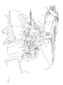
- FIGURE 1 a side portion of a vehicle V is shown carrying a wheelchair lift L for raising a passenger in a wheelchair (not shown) from ground level to a position for entering or leaving the vehicle V.
- the wheelchair lift L may be secured to the rear, side or other appropriate opening of a vehicle.
- the wheelchair lift L is installed at the floor F of the vehicle V to operate through a side doorway D.
- the lift L incorporates: a mobile platform 12 (lower right) for receiving a load such as a passenger in a wheelchair (not shown).
- a hydraulic system 14 (upper left) drives the platform through a parallelogram mechanism 13 as commanded by a control unit 16.
- the parallelogram mechanism 13 actuates the platform 12 in two different motion patterns, i.e., a passenger transporting, horizontal pattern with “raise” and “lower” phases, and a storage motion pattern with “store” (swing up) and “deploy” (swing down) phases.
- a passenger transporting, horizontal pattern with “raise” and “lower” phases and a storage motion pattern with "store” (swing up) and “deploy” (swing down) phases.
- the lift is locked against devious motions that could cause annoyance, damage or personal injury.
- the platform is locked in the stowed position to avoid drift that might occur.
- cooperating parallelogram structures of the mechanisms are interlocked.
- the platform 12 defines a generally rectangular, flat surface 15 that is pivotally connected to the vehicle V through the parallelogram mechanism 13.
- the parallelogram mechanism 13 includes two sets of parallelogram structures, an upper set being larger than a smaller set. Specifically, components of the mechanism form upper, laterally spaced parallelogram structures 17 and lower parallelogram structures 19 (smaller).
- the cooperating pairs of links 22 and 24 each are pivotally connected to a vertical channel arm 27.
- the upper ends 25 of the arms 27 are angled to extend offset from the vertical as illustrated.
- the offset ends 25, with the links 22 and 24, form three sides of the upper parallelogram structures 17.
- a pair of armature brackets 28 are pivotally connected to the links 22 and 24.
- a pair of panels 26 are mounted on the channel arms 27, illustrated only in FIGURE 1.
- the pivotally swinging parallelogram structures 17 are defined.
- a hydraulic ram or cylinder 38 operates in each of the upper parallelogram structures 17 to open and close the parallelogram (see FIGURE 2).
- the lower parallelogram structures 19 retain an open configuration during the transporting raise-lower motion pattern, but collapse or close during the storage motion pattern as a result of forceful engagement with the upper parallelogram structure 17.
- an interlock is provided between the parallelogram structures 17 and 19 during the storage motion pattern.
- the bridge plate 34 performs several functions, specifically, bridge, roll stop and latch.
- the bridge plate 34 is moved by the upper parallelogram structures 17 as a result of displacement of compound cams 35 (FIGURE 1, adjacent end 25, shown in phantom). As described below, the cams 35 position the bridge plate 34 through a cable connection.
- the bridge plate 34 latches the platform 12 to the vehicle floor F through the base 33 (FIGURE 1) rigidly affixed near the bottom of the doorway D.
- the rectangular well or recess 41 in the base 33 engagingly receives a latch member carried on the underside of the bridge plate 34 as described below.
- a release mechanism is mounted on the armature bracket 28 (FIGURE 1) to release the latch.
- the bridge plate 34 is raised as a roll stop or barrier to confine the transported wheelchair.
- elongated side risers or guide rails 30 (lower right) are fixed on each side of the platform 12.
- a pivotal roll stop or end flap 32 is fixed adjacent to the surface 15.
- the flap 32 rotates from a somewhat horizontal ramp position to a vertical barrier or roll stop position.
- Various mechanisms are known for positioning the end flap 32, depending on the location of the platform 12.
- each piston rod 46 is pivotally connected to one of the parallel links 22 at the points of connection to the channel arms 27.
- the opposed ends of each cylinder 38 are pivotally connected to the points of connection of lower parallel links 24 with one of the armature brackets 28.
- the hydraulic system 14 also includes a pump assembly 36 (FIGURE 2) and is affixed to the outside of the rear armature bracket 28 for support.
- a suitable pump assembly 36 such as the Monarch M-259 manufactured by Fluid-Pack, International Ltd., London, Ontario may be used.
- the assembly 36 includes a pump 40 to actuate the cylinders 38, a motor 42 driving the pump and a reservoir 44 to supply and accept fluid to and from the hydraulic drive system 14.
- Fluid passages (not shown in FIGURE 2) accommodate fluid flow between the assembly 36 and the cylinders 38 in forward and reverse directions. It should be noted that the lift L is raised under power but will lower under the force of its own weight.
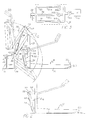
- FIGURE 2 The storage or "stow" motion pattern in which the platform 12 pivots from the entry position E to the vertical position S also is shown in FIGURE 2.
- the platform 12 pivots between the horizontal loading position E and the vertical storage position S by the cooperative motions of the upper and lower parallelogram structures 17 and 19. During the motion, each of the cooperating structures 17 and 19 are interlocked for relative sliding motion.
- Each of the lower parallelogram structures 19 include pivotally interconnected bars 52 and 54 also connected to the platform 12 and the channel arm 27. Again, note that as the parallelogram structures 19 pivotally swing the platform 12 upward, the structures 19 are locked to the links 24 through a saddle block assembly 58 mounted at the pivotal junction of the bars 52 and 54. A headed stud 59, of somewhat mushroom configuration fixed on each of the assemblies 58, is received in a slot as described below to slidingly engage an aligned link 24 (see position E). The locking engagements force the smaller swing-motion parallelograms structures 19 to move somewhat synchronously with the larger parallelogram structures 17.
- a wheelchair passenger wishes to exit the vehicle V.
- the operator selects the "deploy" pattern using the control unit 16 (FIGURE 1).
- This actuates the hydraulic system 14 to open a valve (disclosed below) allowing the platform 12 to swing from the substantially vertical stowed position S to the horizontal entry position E.
- the wheelchair is rolled onto the platform 12 and when the operator selects the "lower" motion pattern, the platform 12, remaining substantially horizontal, eases down to the position G.
- the control functions are reversed to move the platform 12, powered through the raise and stow patterns, ultimately returning to the storage position S.
- Pattern Phases Movement Flow Operation Storage Pattern deploy S to E To Reservoir Swing down from storage position Transport Pattern, lower E to G To Reservoir Horizontal movement to ground Transport pattern, raise G to E To Cylinder (Power) Horizontal movement to vehicle Storage pattern, store E to S To Cylinder (Power) Swing to storage position
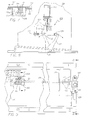
- FIGURE 2 illustrates the hydraulic circuit using substantially standard symbology.
- a hydraulic control 41 represents a unitary block body that is coupled between the cylinders 38 (FIGURES 2 and 3) and the pump 40 which, in turn, is connected to the reservoir 44.
- the pump 40 is active during pattern phases to store and raise the lift 10.
- the control 41 defines three channels, represented in FIGURE 3 by passages 55, 56 and 57.
- the passage 55 defines an orifice 55a and contains a valve 55b.
- the passage 56 defines an orifice 56a and contains a valve 56b.
- the passage 57 is unobstructed but carries a valve 57b.
- Passage Flow Operation (Valve Open) Function 55 Left Movement E to S (store) Present small orifice 56 Right Movement S to E (deploy) Present large orifice 57
- the restricted passages 55 and 56 effect lift movement at similar reduced speeds, the orifice sizes compensating for the weight of the lift accounting for movement during "deploy" while the pump drives the lift during "store”.
- FIGURES 4 and 5 to consider the composite integrated structure of the control 37 as embodied in a block 60.
- the block 60 is affixed in the hydraulic system 16 by screws (not shown) extending through boxes 63 (FIGURE 5).
- the block 60 accommodates fluid flow in multiple paths as described above to enable the lift to move at select speeds.
- a staged bore 74 (left) extends through the block 39 from top to bottom.
- the top portion of the staged bore 74 forms a cavity 78 configured to receive a normally closed spool valve 80 actuated by a solenoid 82.
- an upper bore 72 extends from the cavity 78 to the right-hand side of the block 39 as shown, passing through a bore 69 at a right angle.
- a plug 72a seals the end of the bore 72 opposite the cavity 78.
- a staged bore 76 extends from a region proximate the lower end of bore 74 to the right-hand side of block 39.
- the orifice of the bore 74 is closed by a threaded plug 77 sealed by an "O" ring 106.
- the stage of bore 76, proximate to the end that connects with bore 74, forms a tapered seat 86 for a normally seated movable member or orifice 88.
- the movable unidirectional flow, attenuating orifice 88 has a tapered section 90 to abut the seat 86 when seated (left).
- the movable orifice 88 defines a substantially square outside body section 92 (FIGURE 6).
- the diagonal of the body section 92 is smaller than the diameter of the bore 76, permitting the movable orifice 88 to shift freely within the bore.
- the tapered section 90 defines a relatively small orifice 94 while the body section 92 has a flow passage 96 therethrough and lateral perforations 98 through each of its four sides. Accordingly, the flow passage 96 is in fluid communication with the gaps formed between the sides of the body section 92 and the adjacent surface of the bore 76.
- the movable orifice 88 (FIGURE 5) is biased against the seat 86 by a coil spring 100.
- One end of the spring 100 is recessed in the flow passage 96.
- the other end of the spring 100 abuts a contact surface 102 of a cartridge 104 set in the bore 76.
- An O-ring 104a seals the cartridge 104 in the bore 76.
- a relatively large orifice 105 through the portion of the cartridge proximate the contact surface, intersects with a transverse bore 68 and together they connect the bore 76 to bore 70.
- the relatively small orifice 94 in movable orifice 88 has a diameter that is smaller than the relatively large orifice 105 in the cartridge 104.
- the bore 70 disposed parallel to the bore 74, extends from the top of block 39, intersects the bore 72 and terminates in the mid-portion of a bore 76, connecting the bores 72 and 76.
- a plug 70a seals the entry of the bore 70 opposite the bore 76.
- a bore 69 (coupled to the pump 40) lies orthogonal to the plane formed by the bores 70 and 72. The bore 69 extends from the intersection of bores 70 and 72 to the surface of the block 39.
- Threads on the surface of the lower end of bore 74 form a cylinder port 66 that threadably couples with a cylinder line 67 to connect the block 39 with the cylinders 38.
- the surface of the end of the bore 69 (opposite the intersection with the bores 70 and 72) connects the block 39 to the pump assembly 36.
- one fluid path is from the pump port 69 through the bores 72 and 74, then to the cylinder port 66.
- the path accommodates flow to raise and lower the platform 12 between positions G and E. It is represented by the passage 57 in FIGURE 3.
- a second fluid path is from the pump port 69 through bores 70, 76, and a portion of the bore 74 to the cylinder port 66.
- the path accommodates flow attendant movement between the positions E and S.
- the path is represented in FIGURE 3 by the two paths 55 and 56 passing fluid in two directions, one more restricted than the other. As indicated above, the stowing pattern is powered and, consequently, flow is more restricted to accomplish the desired speed of motion.
- the spool valve 80 is closed.
- the fluid is subjected to relatively smaller pressure as it travels (left to right) from the cylinder port 66 to the pump port 69 forced by the weight of the lift L.
- the movable orifice 88 is unseated, permitting the fluid to pass around and through the movable orifice without substantial obstruction.
- the fluid does encounter the relatively large control orifice 105 for some reduced flow.
- the spool valve 80 When the platform 12 is to be stored or stowed, the spool valve 80 is closed. However, by action of the pump 40, the fluid is subjected to relatively greater pressure as it travels in the direction from the pump port 69 to cylinder port 66. The fluid flows through the bore 70 into the transverse bore 68 and then through the relatively large orifice 105, causing some reduction in the flow rate. Then, the fluid encounters the movable orifice 86 in its seated position so that flow is substantially obstructed to accomplish the desired rate and motion speed as fluid emerges into the bore 74 and passes to the cylinders.
- the orifice sizes are selected so that final flow rates, and consequently the rates of platform movement during both deployment and storage, are substantially equal.
- the operation requires that the effective orifice encountered by the fluid subjected to the higher pressure difference (during storage) be smaller than the effective orifice encountered by the fluid subjected to the lower pressure difference (during deployment).
- the lift L is locked in position by latching the bridge plate 34 (FIGURE 1) to the base 33.
- the bridge plate 34 lies in horizontal facing relationship with the base 33.
- the movements of the bridge plate 34 are described in greater detail below.
- a lock-block 109 (FIGURE 7), affixed to the bottom of the bridge plate 34 drops into the recess 41 in the base 33 fixing the bridge plate 34 to the base 33 and accordingly locking the lift L to the vehicle V.
- the lock-block 109 is affixed to the underside of the bridge plate 34 by a set of fasteners 111.
- the lock-block 109 may be made of a low friction, rigid, plastic material and is of generally parallelepiped configuration, however, defining a horizontal detent 115 at the surface outboard of the vehicle V.
- FIGURE 7 illustrates the mechanism with the lift L in the stowed position S. Accordingly, as the lift L tends to drift, the motion would be as indicated by an arrow 117 to the left as depicted. However, such movement is checked by a latch bar 119 received in the detent 115.
- the latch bar 119 is carried on an elongate rotary shaft or rod 121 that is actuated as disclosed below to pivot the latch bar 119 to a disengaged ramp position as illustrated in phantom by the latch bar 119a. Accordingly, when released, the rod 121 is revolved in a counter clockwise direction and the bridge plate 34 is free to move to the left, as indicated by the arrow 117, the motion being accommodated by the lock-block 109 simply riding over the latch bar 119. Thus, acting through the bridge plate 34, the platform 12, and indeed the entire lift L is locked in the stowed position S (FIGURE 2) until the latch bar 119 is released.
- the mechanism for controlling the latch bar 119 is disclosed in greater detail below along with the somewhat related mechanism for lifting and lowering the bridge plate 34 as it is carried through the different positions by the platform 12.
- the shaft or rod 121 extends laterally through the bridge plate 34 (FIGURE 9) to be mounted external of the bracket 28 (FIGURE 1).
- the exterior of the bracket 28 is shown in FIGURE 8 along with the mechanism 125 for controlling the rod 121.
- the rod 121 carries a crank arm 127, the upper end of which is coupled by a coil spring 129 to holding post 131.
- the coil spring 129 acts as a rigid column holding the crank arm 127 positioned to the right as illustrated in FIGURE 8. Accordingly, the latch bar 119 (FIGURE 7) is held in locking engagement with the lock-block 109.
- the coil spring 129 is "broken", simply bent to accommodate a leftward pivotal motion by the crank arm 127. The bending or “breaking" of the spring 129 allows it to be driven to a loop, as shown in phantom, and is accomplished by a wire loop 132 affixed to the armature of a solenoid 133.
- the solenoid 133 is pulsed when the control unit 16 is actuated to initiate lowering the lift from the stowed position S. Accordingly, when the solenoid 133 is energized, its armature raises the wire loop 132 "breaking" the spring 129 into an inverted “U”-shaped configuration. Consequently, the crank arm 127 swings to the left (as illustrated) revolving the shaft 121 to disengage the latch bar 119, moving it into a ramp position as indicated by the phantom bar 119a (FIGURE 7).
- the bridge plate 34 not only serves as a locking element and a bridge ramp, but additionally functions as an inward roll stop. Consequently, the bridge plate 34 (FIGURE 1) is variously positioned between substantially vertical and substantially horizontal positions as the lift is raised and lowered. Generally, as indicated above, the operation is accomplished by a pair of similar cams 35 (FIGURE 1) driven by the upper parallelograms 17 to actuate cables coupled to the bridge plate 34.
- the motion of the bridge plate 34 is meaningful in relation to the platform surface 15.
- the bridge plate 34 is somewhat vertical functioning as a roll stop.
- the bridge plate 34 remains in the somewhat vertical position during the raise-lower motion pattern between the positions G and E.
- the bridge plate 34 swings down to a parallel position substantially flush with the platform surface 15, bridging the space to the base 33.
- the wheelchair is afforded a smooth surface into the vehicle V.
- the bridge plate 34 when the platform 12 moves from a substantially horizontal position to a substantially vertical position, the bridge plate 34 again becomes substantially perpendicular to the surface 15. That is, when the platform 12 is vertical in the stowed position S, the bridge plate 34 is substantially horizontal functioning as a latch member, as described above, to accomplish the positions of the bridge plate 34, the cam 35, actuated by the upper parallelogram 17, in turn, actuates a cable connected to the bridge plate 34. Again, similar cams 35 with cables are provided on each side of the lift mounted on the channel arms 27.
- the cam 35 is pivotally mounted on a bearing pin 140 at an upward location in the channel arm 27.
- a cam follower 142 rides over the compound cam edge 144 to variously position its top end 146 which carries a pulley 148.
- a cable 150 rides on the pulley 148 with an upper end anchored in the end 25 of the channel arm 27. The opposed end of the cable 150 threads through a series of pulleys, as illustrated in FIGURE 11, and is connected to the bridge plate 34.
- the cable 150 is anchored to the channel arm 27 by a stud 152.
- the cable then extends from the stud 152 over an idler 154, the pulley 148 and a pair of pulleys 156 and 158 to extend downwardly within the channel arm 27.
- the cable 150 is received over another pulley 160 before passing to an attachment 162 on the bridge plate 34.
- the cam edge 144 (FIGURE 12) defines three distinct cam drives.
- the uppermost arcuate section 166 engages the cam follower 142 to be swung out from the channel arm 27, raising the bridge plate 34 to the position illustrated in FIGURE 1.
- the collapsing upper parallelogram 17 is accommodated by the arcuate section 166 of the cam holding the bridge plate 34 somewhat vertical until the section 168 engages the cam follower 142 to lower the bridge plate 34.
- the last section 170 of the cam becomes active to set the bridge plate 34 somewhat perpendicular to the surface 15. Accordingly, the bridge plate 34 is horizontal for the locking engagement as described above.
- a need is recognized to interlock the upper and lower parallelograms 17 and 19 so as to force cooperative motions as the lift L moves between the positions S and E.
- the locking engagement is accomplished by the saddle block 58 (FIGURE 2) being engaged to the parallel link 24 during the cooperative pivotal motion pattern.
- FIGURE 13 shows the saddle block assembly 58 somewhat enlarged form along with the supporting pivot bars 52 and 54 and the parallel link 24.
- the sectional view of FIGURE 14 illustrates the selective locked engagement between the saddle lock assembly 58 and the parallel link 24 as now will be considered in greater detail.
- the saddle block assembly 58 includes a yoke section 182 of channel configuration with a sliding shoe 184 of frictionless plastic set to engage the parallel link 24 (FIGURE 13).
- a capped stud 186 Extending from the yoke section 182 through the shoe 84 is a capped stud 186 of a somewhat "mushroom" configuration.
- a circular opening 188 is provided in the parallel link 24 aligned with the stud 186 when the lift is in the entry position E as illustrated in FIGURE 2.
- Extending from the opening 188, parallel with the link 24, is a slot 190 to accommodate the short shaft 192 of the stud 186 with the head 194 inside the slot 190.
- the head 194 of the stud 186 enters the opening 188 as the lift is raised into the entry position E.
- the lower parallelogram 19 is locked to the upper parallelogram 17.
- the stud 186 is slidingly engaged with the link 24, locking the saddle block assembly in sliding engagement.
- the two parallelogram structures 17 and 19 move in a cooperative action as the lift L moves between the entry position E and the stowed position S.
- the lower parallelogram structure 19 is forced to open, allowing the platform 12 to swing down.
- the stud 86 allows withdrawal of the saddle block assembly 58, permitting the two parallelogram structures 17 and 19 to separate and accommodate the independent transporting platform motion patterns.
Abstract
Description
- This invention relates to wheelchair lifts for vehicles, of a kind in which a platform structure for carrying the wheelchair is mounted on a pivotal mechanism which is for attachment to the vehicle and which is selectively operable to move the platform structure from one to another of at least two defined positions, and a bridge plate is pivotally attached to the platform structure for bridging a gap between the platform structure and the vehicle in a first of said two positions.
- A wheelchair lift of this above-specified kind is known from WO-A-9214431, and involves a wheelchair-platform structure which comprises two platform parts. The outer of the two parts is pivoted upwardly from the inner, fixed part when the lift is stowed in a storage compartment below the passenger floor of a vehicle, and a hydraulic actuator carried by the inner part is used to pivot the outer part down into alignment with the inner part when the platform is to be deployed, and then up when it is to be stowed again.
- When the platform of the known lift has been deployed from the stowed position, further hydraulic actuators are operated appropriately to lower it to a loading position on the ground or to raise it from that position to an entry position level with the floor of the vehicle. Another hydraulic actuator coupled to a normally upright barrier or bridge plate at the rear of the platform, is operated when the platform reaches the entry position to pivot the plate down. The plate when pivoted down in this way bridges the gap between the platform and the vehicle floor to enable wheelchairs to pass readily in either direction between the platform and vehicle.
- It is an object of the present invention to provide a form of wheelchair lift of the said above-specified kind that has advantages over the known form.
- According to the present invention a wheelchair lift of the said above-specified kind is characterised in that the bridge plate is adapted such that when the platform structure is in the second of said two positions it is effectively locked to the vehicle in that position via the bridge plate.
- With the known wheelchair lift the outer part of the platform is held in the upright, stowed position only by its hydraulic actuator, and since hydraulic systems are susceptible to leakage, there is the problem, particularly over any extended period of time, that the outer part of the platform will tend to drift down causing inconvenience and possible danger.
- The wheelchair lift of the present invention has the advantage over the known lift of utilising the bridge plate to establish an effective lock on the platform structure that may be utilised to hold it in a stowed position. More particularly, a selectively-releasable locking mechanism for attachment to the vehicle may be operative to block movement of the bridge plate, and thereby of the platform structure, when the platform structure is in its stowed or other second position. The locking mechanism may be held in its operative condition by resilient restraint, and means may then be provided for selectively deflecting the resilient restraint such as to release the locking mechanism from its operative condition and thereby enable the platform structure to move.
- The bridge plate of the invention may have a lock-block for entering a well defined in a base attached to the vehicle, when the platform structure moves into said second position. The lock-block, which may be carried on the underside of the bridge plate, may be obstructed in movement within the well by a part of a crank mechanism. The crank mechanism may be acted on by a spring for resiliently biasing it into a position in which said part provides the obstruction. In these latter circumstances, a solenoid may be provided for selectively deflecting the spring and thereby redirecting the resilient bias such as to move said part into a position in which movement of the lock-block within the well is substantially unobstructed.
- A wheelchair lift in accordance with the present invention will now be described, by way of example, with reference to the accompanying drawings , in which:
- FIGURE 1 is a perspective view illustrating a partial side view of a vehicle carrying a wheelchair lift in accordance with the present invention;
- FIGURE 2 is a side elevational view of a portion of the wheelchair lift shown in FIGURE 1 illustrating different motion patterns thereof;
- FIGURE 3 is a hydraulic circuit diagram of the power system embodied in the wheelchair lift of FIGURE 1;
- FIGURE 4 is a top plan view, partially cut away, of the flow control valve body embodied in the wheelchair lift of FIGURE 1;
- FIGURE 5 is a cross-sectional view taken along line 5-5 of FIGURE 4;
- FIGURE 6 is a sectional view taken along line 6-6 of FIGURE 5;
- FIGURE 7 is a fragmentary perspective view illustrating a lock embodied in the wheelchair lift of FIGURE 1;
- FIGURE 8 is a fragmentary side view of the lock structure for the lock as shown in FIGURE 7;
- FIGURE 9 is a plan view of the structure of FIGURE 8 illustrating the lock arrangement;
- FIGURE 10 is a fragmentary side elevation illustrating an actuating mechanism embodied in the wheelchair lift of FIGURE 1;
- FIGURE 11 is a fragmentary side elevation somewhat similar to FIGURE 10 showing a cable circuit;
- FIGURE 12 is a plan view of a cam actuator as embodied in the structures of FIGURES 10 and 11;
- FIGURE 13 is a fragmentary side elevation of a locking mechanism as embodied in the lift of FIGURE 1;
- FIGURE 14 is a sectional view taken along line 14-14 of FIGURE 13; and
- FIGURE 15 is a sectional view taken through the structure of FIGURE 14.
-
- As required, a detailed illustrative embodiment of the invention is disclosed. However, it is to be understood that the invention is not limited in its application to the details of construction or the arrangement of parts as illustrated in the accompanying drawings and description, since the invention is capable of other embodiments and of being practised or carried out in various ways.
- Referring now to FIGURE 1, a side portion of a vehicle V is shown carrying a wheelchair lift L for raising a passenger in a wheelchair (not shown) from ground level to a position for entering or leaving the vehicle V. The wheelchair lift L may be secured to the rear, side or other appropriate opening of a vehicle. As illustrated in FIGURE 1, the wheelchair lift L is installed at the floor F of the vehicle V to operate through a side doorway D. Structurally, the lift L incorporates: a mobile platform 12 (lower right) for receiving a load such as a passenger in a wheelchair (not shown). A hydraulic system 14 (upper left) drives the platform through a
parallelogram mechanism 13 as commanded by acontrol unit 16. - As indicated, the
parallelogram mechanism 13 actuates theplatform 12 in two different motion patterns, i.e., a passenger transporting, horizontal pattern with "raise" and "lower" phases, and a storage motion pattern with "store" (swing up) and "deploy" (swing down) phases. Generally, in accordance herewith, the lift is locked against devious motions that could cause annoyance, damage or personal injury. Specifically, the platform is locked in the stowed position to avoid drift that might occur. Also, in the swing motion pattern, cooperating parallelogram structures of the mechanisms are interlocked. - Considering the elements in greater detail, the
platform 12 defines a generally rectangular,flat surface 15 that is pivotally connected to the vehicle V through theparallelogram mechanism 13. Structurally, theparallelogram mechanism 13 includes two sets of parallelogram structures, an upper set being larger than a smaller set. Specifically, components of the mechanism form upper, laterally spacedparallelogram structures 17 and lower parallelogram structures 19 (smaller). - The
upper parallelogram structures 17, sometimes referred to as armatures, each include upper and lowerparallel links links 22 are horizontally aligned and each is vertically aligned with acooperating link 24. - At the outboard ends (away from the vehicle V) the cooperating pairs of
links vertical channel arm 27. Theupper ends 25 of thearms 27 are angled to extend offset from the vertical as illustrated. The offset ends 25, with thelinks upper parallelogram structures 17. To form the fourth (inboard) side, a pair ofarmature brackets 28 are pivotally connected to thelinks panels 26 are mounted on thechannel arms 27, illustrated only in FIGURE 1. Thus, the pivotally swingingparallelogram structures 17 are defined. - In the operation of the lift L, a hydraulic ram or
cylinder 38 operates in each of theupper parallelogram structures 17 to open and close the parallelogram (see FIGURE 2). Somewhat independently, thelower parallelogram structures 19 retain an open configuration during the transporting raise-lower motion pattern, but collapse or close during the storage motion pattern as a result of forceful engagement with theupper parallelogram structure 17. As described in detail below, and in accordance herewith, an interlock is provided between theparallelogram structures - The movement of the
upper parallelogram structures 17, accomplished by thehydraulic cylinders 38, also positions a roll stop orbridge plate 34 hinged to the inboard edge of theplatform 12. As described in detail below, thebridge plate 34 performs several functions, specifically, bridge, roll stop and latch. - The
bridge plate 34 is moved by theupper parallelogram structures 17 as a result of displacement of compound cams 35 (FIGURE 1,adjacent end 25, shown in phantom). As described below, thecams 35 position thebridge plate 34 through a cable connection. - Generally, as treated in greater detail below, the
bridge plate 34 latches theplatform 12 to the vehicle floor F through the base 33 (FIGURE 1) rigidly affixed near the bottom of the doorway D. Note the rectangular well or recess 41 in thebase 33 engagingly receives a latch member carried on the underside of thebridge plate 34 as described below. A release mechanism is mounted on the armature bracket 28 (FIGURE 1) to release the latch. - As shown in FIGURE 1, the
bridge plate 34 is raised as a roll stop or barrier to confine the transported wheelchair. For a similar purpose, elongated side risers or guide rails 30 (lower right) are fixed on each side of theplatform 12. At the outboard or front end of theplatform 12, a pivotal roll stop orend flap 32 is fixed adjacent to thesurface 15. As also seen in FIGURE 2, for boarding the platform from ground level, theflap 32 rotates from a somewhat horizontal ramp position to a vertical barrier or roll stop position. Various mechanisms are known for positioning theend flap 32, depending on the location of theplatform 12. - In FIGURE 2, the wheelchair lift L is illustrated in three positions: stowed position S (phantom lines), entry position E (solid lines) and lowered loading position G (phantom lines). As generally indicated above, a pair of spaced apart
hydraulic cylinders 38, each with an axially alignedpiston rod 46, drive theparallelogram mechanism 13 to a closed configuration. That is, remote from thecylinders 38, eachpiston rod 46 is pivotally connected to one of theparallel links 22 at the points of connection to thechannel arms 27. The opposed ends of eachcylinder 38 are pivotally connected to the points of connection of lowerparallel links 24 with one of thearmature brackets 28. - The
hydraulic system 14 also includes a pump assembly 36 (FIGURE 2) and is affixed to the outside of therear armature bracket 28 for support. Asuitable pump assembly 36 such as the Monarch M-259 manufactured by Fluid-Pack, International Ltd., London, Ontario may be used. Theassembly 36 includes apump 40 to actuate thecylinders 38, amotor 42 driving the pump and areservoir 44 to supply and accept fluid to and from thehydraulic drive system 14. Fluid passages (not shown in FIGURE 2) accommodate fluid flow between theassembly 36 and thecylinders 38 in forward and reverse directions. It should be noted that the lift L is raised under power but will lower under the force of its own weight. - Consider the motion patterns in greater detail. From the ground position G, driven by the
cylinder rods 46, theparallelogram structures 17 swing upwardly until theplatform 12 is level with the floor F of the vehicle V (position E). Note thatparallelogram structures 17 maintain theplatform 12 in a substantially horizontal position as it is raised or lowered between ground level and the vehicle floor. During such motion, the smallerlower parallelogram structures 19 are unchanged in an open configuration. - The storage or "stow" motion pattern in which the
platform 12 pivots from the entry position E to the vertical position S also is shown in FIGURE 2. Theplatform 12 pivots between the horizontal loading position E and the vertical storage position S by the cooperative motions of the upper andlower parallelogram structures structures - Each of the
lower parallelogram structures 19 include pivotallyinterconnected bars platform 12 and thechannel arm 27. Again, note that as theparallelogram structures 19 pivotally swing theplatform 12 upward, thestructures 19 are locked to thelinks 24 through asaddle block assembly 58 mounted at the pivotal junction of thebars stud 59, of somewhat mushroom configuration fixed on each of theassemblies 58, is received in a slot as described below to slidingly engage an aligned link 24 (see position E). The locking engagements force the smaller swing-motion parallelograms structures 19 to move somewhat synchronously with thelarger parallelogram structures 17. - To consider the overall operations in greater detail, assume a wheelchair passenger wishes to exit the vehicle V. The operator selects the "deploy" pattern using the control unit 16 (FIGURE 1). This actuates the
hydraulic system 14 to open a valve (disclosed below) allowing theplatform 12 to swing from the substantially vertical stowed position S to the horizontal entry position E. The wheelchair is rolled onto theplatform 12 and when the operator selects the "lower" motion pattern, theplatform 12, remaining substantially horizontal, eases down to the position G. After the wheelchair is off theplatform 12, the control functions are reversed to move theplatform 12, powered through the raise and stow patterns, ultimately returning to the storage position S. - Recapitulating to some extent, the lift has four distinct motion phases of two patterns as set forth below. For each phase, there is a different hydraulic mode.
Pattern Phases Movement Flow Operation Storage Pattern, deploy S to E To Reservoir Swing down from storage position Transport Pattern, lower E to G To Reservoir Horizontal movement to ground Transport pattern, raise G to E To Cylinder (Power) Horizontal movement to vehicle Storage pattern, store E to S To Cylinder (Power) Swing to storage position - Turning now to the hydraulics, control of the speed at which the passenger lift moves through the different patterns resides in a valve body 39 (FIGURE 2) which is part of the
pump assembly 36. In the disclosed embodiment, a lightweight aluminum block is machined or otherwise formed to define multiple passageways and receive control members. FIGURE 3 illustrates the hydraulic circuit using substantially standard symbology. - Generally, a
hydraulic control 41 represents a unitary block body that is coupled between the cylinders 38 (FIGURES 2 and 3) and thepump 40 which, in turn, is connected to thereservoir 44. Thepump 40 is active during pattern phases to store and raise the lift 10. - The
control 41 defines three channels, represented in FIGURE 3 bypassages passage 55 defines anorifice 55a and contains avalve 55b. Similarly, thepassage 56 defines anorifice 56a and contains avalve 56b. Thepassage 57 is unobstructed but carries avalve 57b. The functions of the passages are summarized as follows:Passage Flow Operation (Valve Open) Function 55 Left Movement E to S (store) Present small orifice 56 Right Movement S to E (deploy) Present large orifice 57 Bidirectional Movement L to E (raise) and E to L (lower) Accommodate lifting and lowering operation - The restricted
passages - Reference now will be made to FIGURES 4 and 5 to consider the composite integrated structure of the
control 37 as embodied in ablock 60. Note that theblock 60 is affixed in thehydraulic system 16 by screws (not shown) extending through boxes 63 (FIGURE 5). Generally, theblock 60 accommodates fluid flow in multiple paths as described above to enable the lift to move at select speeds. - Considering the structure of the block 39 (FIGURE 5) in greater detail, a staged bore 74 (left) extends through the
block 39 from top to bottom. The top portion of the staged bore 74 forms acavity 78 configured to receive a normally closedspool valve 80 actuated by asolenoid 82. Transverse to thebore 74, anupper bore 72 extends from thecavity 78 to the right-hand side of theblock 39 as shown, passing through abore 69 at a right angle. Aplug 72a seals the end of thebore 72 opposite thecavity 78. - Below the
bore 72 and transverse to thebore 74, a staged bore 76 extends from a region proximate the lower end ofbore 74 to the right-hand side ofblock 39. The orifice of thebore 74 is closed by a threadedplug 77 sealed by an "O"ring 106. The stage ofbore 76, proximate to the end that connects withbore 74, forms atapered seat 86 for a normally seated movable member ororifice 88. The movable unidirectional flow, attenuatingorifice 88, has a tapered section 90 to abut theseat 86 when seated (left). - Referring additionally to FIGURE 6, the
movable orifice 88 defines a substantially square outside body section 92 (FIGURE 6). The diagonal of thebody section 92 is smaller than the diameter of thebore 76, permitting themovable orifice 88 to shift freely within the bore. The tapered section 90 defines a relativelysmall orifice 94 while thebody section 92 has aflow passage 96 therethrough andlateral perforations 98 through each of its four sides. Accordingly, theflow passage 96 is in fluid communication with the gaps formed between the sides of thebody section 92 and the adjacent surface of thebore 76. - The movable orifice 88 (FIGURE 5) is biased against the
seat 86 by acoil spring 100. One end of thespring 100 is recessed in theflow passage 96. The other end of thespring 100 abuts acontact surface 102 of acartridge 104 set in thebore 76. An O-ring 104a seals thecartridge 104 in thebore 76. - A relatively
large orifice 105, through the portion of the cartridge proximate the contact surface, intersects with a transverse bore 68 and together they connect thebore 76 to bore 70. The relativelysmall orifice 94 inmovable orifice 88 has a diameter that is smaller than the relativelylarge orifice 105 in thecartridge 104. These orifices coincide to therepresentative orifices - The
bore 70, disposed parallel to thebore 74, extends from the top ofblock 39, intersects thebore 72 and terminates in the mid-portion of abore 76, connecting thebores plug 70a seals the entry of thebore 70 opposite thebore 76. A bore 69 (coupled to the pump 40) lies orthogonal to the plane formed by thebores bore 69 extends from the intersection ofbores block 39. - Threads on the surface of the lower end of
bore 74 form acylinder port 66 that threadably couples with acylinder line 67 to connect theblock 39 with thecylinders 38. As indicated above, the surface of the end of the bore 69 (opposite the intersection with thebores 70 and 72) connects theblock 39 to thepump assembly 36. - Turning now to the operation of the flow control means, one fluid path is from the
pump port 69 through thebores cylinder port 66. The path accommodates flow to raise and lower theplatform 12 between positions G and E. It is represented by thepassage 57 in FIGURE 3. - A second fluid path is from the
pump port 69 throughbores bore 74 to thecylinder port 66. The path accommodates flow attendant movement between the positions E and S. The path is represented in FIGURE 3 by the twopaths - To summarize, consider the distinct motion patterns of deploying the lift L, raising and lowering (with or without a passenger) and storing the lift. For deployment, the
spool valve 80 is closed. The fluid is subjected to relatively smaller pressure as it travels (left to right) from thecylinder port 66 to thepump port 69 forced by the weight of the lift L. As the fluid enters thebore 76, themovable orifice 88 is unseated, permitting the fluid to pass around and through the movable orifice without substantial obstruction. However, the fluid does encounter the relativelylarge control orifice 105 for some reduced flow. - When the
platform 12 is to be stored or stowed, thespool valve 80 is closed. However, by action of thepump 40, the fluid is subjected to relatively greater pressure as it travels in the direction from thepump port 69 tocylinder port 66. The fluid flows through thebore 70 into the transverse bore 68 and then through the relativelylarge orifice 105, causing some reduction in the flow rate. Then, the fluid encounters themovable orifice 86 in its seated position so that flow is substantially obstructed to accomplish the desired rate and motion speed as fluid emerges into thebore 74 and passes to the cylinders. - The orifice sizes are selected so that final flow rates, and consequently the rates of platform movement during both deployment and storage, are substantially equal. The operation requires that the effective orifice encountered by the fluid subjected to the higher pressure difference (during storage) be smaller than the effective orifice encountered by the fluid subjected to the lower pressure difference (during deployment).
- In view of the above description of the motion patterns for the lift L, consideration now will be given to certain structures and operations as treated above only in a general manner. Accordingly, assume that the lift L is in the stowed position S (FIGURE 2) collapsed within the vehicle V. So positioned, if free, the lift L would drop to the entry position E under the force of gravity. However, it is restrained by the
extended piston rods 46 of thecylinders 38. The problem is that hydraulic systems are susceptible to leakage, particularly over extended time intervals. Consequently, fluid tends to pass out of thecylinders 38, allowing the lift L to drift down. Typically, at some point, the lift L will engage an interior surface of the vehicle V. Rattles and marred surfaces are often the result. - If the lift L abuts a door of the vehicle V, it may impede the operation of the door. Thus, a need exists to fasten or lock the lift L in the stowed position S.
- As generally indicated above, the lift L is locked in position by latching the bridge plate 34 (FIGURE 1) to the
base 33. Specifically, when the lift L is in the stowed position S, thebridge plate 34 lies in horizontal facing relationship with thebase 33. The movements of thebridge plate 34 are described in greater detail below. However, generally, a lock-block 109 (FIGURE 7), affixed to the bottom of thebridge plate 34 drops into therecess 41 in the base 33 fixing thebridge plate 34 to thebase 33 and accordingly locking the lift L to the vehicle V. Detailed parts and operations of the structure will now be treated with reference to FIGURES 7, 8 and 9. - As shown in FIGURE 7, the lock-
block 109 is affixed to the underside of thebridge plate 34 by a set of fasteners 111. Note that the lock-block 109 may be made of a low friction, rigid, plastic material and is of generally parallelepiped configuration, however, defining ahorizontal detent 115 at the surface outboard of the vehicle V. - FIGURE 7 illustrates the mechanism with the lift L in the stowed position S. Accordingly, as the lift L tends to drift, the motion would be as indicated by an
arrow 117 to the left as depicted. However, such movement is checked by alatch bar 119 received in thedetent 115. - The
latch bar 119 is carried on an elongate rotary shaft orrod 121 that is actuated as disclosed below to pivot thelatch bar 119 to a disengaged ramp position as illustrated in phantom by the latch bar 119a. Accordingly, when released, therod 121 is revolved in a counter clockwise direction and thebridge plate 34 is free to move to the left, as indicated by thearrow 117, the motion being accommodated by the lock-block 109 simply riding over thelatch bar 119. Thus, acting through thebridge plate 34, theplatform 12, and indeed the entire lift L is locked in the stowed position S (FIGURE 2) until thelatch bar 119 is released. - As indicated, the mechanism for controlling the
latch bar 119 is disclosed in greater detail below along with the somewhat related mechanism for lifting and lowering thebridge plate 34 as it is carried through the different positions by theplatform 12. - The shaft or
rod 121, as shown in FIGURE 7, extends laterally through the bridge plate 34 (FIGURE 9) to be mounted external of the bracket 28 (FIGURE 1). The exterior of thebracket 28 is shown in FIGURE 8 along with themechanism 125 for controlling therod 121. - At the base of the
bracket 28, therod 121 carries acrank arm 127, the upper end of which is coupled by acoil spring 129 to holdingpost 131. Functionally, thecoil spring 129 acts as a rigid column holding thecrank arm 127 positioned to the right as illustrated in FIGURE 8. Accordingly, the latch bar 119 (FIGURE 7) is held in locking engagement with the lock-block 109. To release thelatch bar 119, thecoil spring 129 is "broken", simply bent to accommodate a leftward pivotal motion by thecrank arm 127. The bending or "breaking" of thespring 129 allows it to be driven to a loop, as shown in phantom, and is accomplished by awire loop 132 affixed to the armature of asolenoid 133. Thesolenoid 133 is pulsed when thecontrol unit 16 is actuated to initiate lowering the lift from the stowed position S. Accordingly, when thesolenoid 133 is energized, its armature raises thewire loop 132 "breaking" thespring 129 into an inverted "U"-shaped configuration. Consequently, thecrank arm 127 swings to the left (as illustrated) revolving theshaft 121 to disengage thelatch bar 119, moving it into a ramp position as indicated by the phantom bar 119a (FIGURE 7). - Note that the rotary motion of the
shaft 121 is accommodated by bearingmounts 135 as illustrated in FIGURE 9. Also, it is noteworthy that, if necessary, the release can be manually actuated simply by manually "breaking" the spring 129 (FIGURE 8) to disengage the latch bar 119 (FIGURE 7). Accordingly, an effective and convenient locking arrangement is provided, acting effectively through thebridge plate 34 to fix the lift L rigidly in the stowed position S. - As indicated above, the
bridge plate 34 not only serves as a locking element and a bridge ramp, but additionally functions as an inward roll stop. Consequently, the bridge plate 34 (FIGURE 1) is variously positioned between substantially vertical and substantially horizontal positions as the lift is raised and lowered. Generally, as indicated above, the operation is accomplished by a pair of similar cams 35 (FIGURE 1) driven by theupper parallelograms 17 to actuate cables coupled to thebridge plate 34. - The motion of the
bridge plate 34 is meaningful in relation to theplatform surface 15. When theplatform 12 is lowered and theplatform surface 15 is substantially horizontal, as depicted in FIGURE 1, thebridge plate 34 is somewhat vertical functioning as a roll stop. Thebridge plate 34 remains in the somewhat vertical position during the raise-lower motion pattern between the positions G and E. However, at the end of that motion pattern, thebridge plate 34 swings down to a parallel position substantially flush with theplatform surface 15, bridging the space to thebase 33. Thus, the wheelchair is afforded a smooth surface into the vehicle V. - During the stow motion pattern, when the
platform 12 moves from a substantially horizontal position to a substantially vertical position, thebridge plate 34 again becomes substantially perpendicular to thesurface 15. That is, when theplatform 12 is vertical in the stowed position S, thebridge plate 34 is substantially horizontal functioning as a latch member, as described above, to accomplish the positions of thebridge plate 34, thecam 35, actuated by theupper parallelogram 17, in turn, actuates a cable connected to thebridge plate 34. Again,similar cams 35 with cables are provided on each side of the lift mounted on thechannel arms 27. - As illustrated in FIGURE 10, the
cam 35 is pivotally mounted on abearing pin 140 at an upward location in thechannel arm 27. Thus, acam follower 142 rides over thecompound cam edge 144 to variously position itstop end 146 which carries apulley 148. Acable 150 rides on thepulley 148 with an upper end anchored in theend 25 of thechannel arm 27. The opposed end of thecable 150 threads through a series of pulleys, as illustrated in FIGURE 11, and is connected to thebridge plate 34. - As illustrated in FIGURE 11, the
cable 150 is anchored to thechannel arm 27 by astud 152. The cable then extends from thestud 152 over an idler 154, thepulley 148 and a pair ofpulleys channel arm 27. At a location just above thebridge plate 34, thecable 150 is received over anotherpulley 160 before passing to anattachment 162 on thebridge plate 34. - The cam edge 144 (FIGURE 12) defines three distinct cam drives. The uppermost
arcuate section 166 engages thecam follower 142 to be swung out from thechannel arm 27, raising thebridge plate 34 to the position illustrated in FIGURE 1. As theplatform 12 is raised, the collapsingupper parallelogram 17 is accommodated by thearcuate section 166 of the cam holding thebridge plate 34 somewhat vertical until thesection 168 engages thecam follower 142 to lower thebridge plate 34. With further upward movement by the lift L, thelast section 170 of the cam becomes active to set thebridge plate 34 somewhat perpendicular to thesurface 15. Accordingly, thebridge plate 34 is horizontal for the locking engagement as described above. - Recapitulating to some extent, while the lift is locked in the stowed position S (FIGURE 2) when it is released and the
hydraulic cylinders 38 are relieved, the lift swings downward, as described above, positioning theplatform 12 substantially horizontal at the entry position E by the cooperative action of the upper andlower parallelogram structures upper parallelogram structure 17 may begin to swing down while thelower parallelogram structure 19 remains somewhat collapsed. As a consequence, a danger exists that theupper parallelogram structure 17 may substantially open with thelower parallelogram structure 19 remaining closed up to some point at which the lower parallelogram structure opens, allowing the platform P a pivotal free fall. Essentially, in accordance herewith, a need is recognized to interlock the upper andlower parallelograms parallel link 24 during the cooperative pivotal motion pattern. - FIGURE 13 shows the
saddle block assembly 58 somewhat enlarged form along with the supporting pivot bars 52 and 54 and theparallel link 24. The sectional view of FIGURE 14 illustrates the selective locked engagement between thesaddle lock assembly 58 and theparallel link 24 as now will be considered in greater detail. - As indicated above, the
saddle block assembly 58 includes ayoke section 182 of channel configuration with a slidingshoe 184 of frictionless plastic set to engage the parallel link 24 (FIGURE 13). Extending from theyoke section 182 through the shoe 84 is a cappedstud 186 of a somewhat "mushroom" configuration. For mating engagement with thestud 186, acircular opening 188 is provided in theparallel link 24 aligned with thestud 186 when the lift is in the entry position E as illustrated in FIGURE 2. Extending from theopening 188, parallel with thelink 24, is aslot 190 to accommodate theshort shaft 192 of thestud 186 with thehead 194 inside theslot 190. Accordingly, thehead 194 of thestud 186 enters theopening 188 as the lift is raised into the entry position E. With continued raising of the lift L, thelower parallelogram 19 is locked to theupper parallelogram 17. Specifically, thestud 186 is slidingly engaged with thelink 24, locking the saddle block assembly in sliding engagement. Accordingly, the twoparallelogram structures upper parallelogram 17 begins to swing outwardly, thelower parallelogram structure 19 is forced to open, allowing theplatform 12 to swing down. As explained above, when theplatform 12 attains the entry position, thestud 86 allows withdrawal of thesaddle block assembly 58, permitting the twoparallelogram structures - In view of the above, it is apparent that the structure mechanisms as described accommodate desired and safe motion patterns as a result of interrelated structures. As indicated, various departures from the structures are possible and will be apparent to persons of skill in the art. However, the importance herewith, the scope hereof is deemed to be appropriately determined with reference primarily to the claims as set forth below.
Claims (12)
- A wheelchair lift (L) for a vehicle (V), in which a platform structure (12) for carrying the wheelchair is mounted on a pivotal mechanism (13) which is for attachment to the vehicle (V) and which is selectively operable to move the platform structure (12) from one to another of at least two defined positions (G,E,S), and a bridge plate (34) is pivotally attached to the platform structure (12) for bridging a gap between the platform structure (12) and the vehicle (V) in a first of said two positions (E), characterised in that the bridge plate (34) is adapted such that when the platform structure (12) is in the second of said two positions (S) it is effectively locked to the vehicle (V) in that position (S) via the bridge plate (34).
- A wheelchair lift (L) according to Claim 1 wherein the platform structure (12) is selectively operable to move between a loading position (G), an entry position (E) and a stowed position (S), and said second position is the stowed position (S).
- A wheelchair lift (L) according to Claim 2 wherein the bridge plate (34) is angled to act as a roll stop while the platform structure (12) is in the loading position (G).
- A wheelchair lift (L) according to any one of Claims 1 to 3 wherein a selectively-releasable locking mechanism (119,121,127) for attachment to the vehicle (V), is operative to block movement of the bridge plate (34), and thereby of the platform structure (12), when the platform structure (12) is in its second position (S).
- A wheelchair lift (L) according to Claim 4 wherein the locking mechanism (119,121,127) is held in its operative condition by resilient restraint (129), and means (133) is selectively operable for deflecting the resilient restraint (129) such as to release the locking mechanism (119,121,127) from its operative condition and thereby enable the platform structure (12) to move from said second position (S).
- A wheelchair lift (L) according to any one of Claims 1 to 5 wherein the bridge plate (34) has a lock-block (109) for entering a well (41) defined in a base (37) attached to the vehicle (V), when the platform structure (12) moves into said second position (S).
- A wheelchair lift (L) according to Claim 6 wherein the lock-block (109) is carried on the underside of the bridge plate (34).
- A wheelchair lift (L) according to Claim 6 or Claim 7 wherein a crank mechanism (121,127) has a part (119) for obstructing movement of the lock-block (109) within the well (41) such as effectively to lock the platform structure (12) in the second position (S) as aforesaid.
- A wheelchair lift (L) according to Claim 8 wherein a spring (129) acts upon the crank mechanism (121,127) for resiliently biasing it into a position in which said part obstructs movement of the lock-block (109) within the well (41), and a solenoid (133) is operable for selectively deflecting the spring (129) and thereby redirecting the resilient bias such that said part (119) moves into a position in which movement of the lock-block (109) within the well (41) is substantially unobstructed.
- A wheelchair lift (L) according to any one of Claims 1 to 9 wherein the pivotal mechanism (13) comprises at least one pair of lower supporting pivot bars (19) and at least one upper parallelogram structure (17) which are releasably interlocked with one another during a predetermined part of the movement of the platform structure (12).
- A wheelchair lift (L) according to any one of Claims 1 to 10 wherein the pivotal mechanism (13) includes drive means (38) that is operable to open and close the parallelogram structure (17) for moving the platform structure (12) between its defined positions (G,E,S).
- A wheelchair lift (L) according to any one of Claims 1 to 11 including a cam mechanism (142,144) for raising and lowering the bridge plate (34) in accordance with movement of the platform structure (12) between its defined positions (G,E,S).
Applications Claiming Priority (3)
| Application Number | Priority Date | Filing Date | Title |
|---|---|---|---|
| US114774 | 1993-08-31 | ||
| US08/114,774 US5445488A (en) | 1992-07-28 | 1993-08-31 | Locking wheelchair lift |
| EP94917257A EP0716588B1 (en) | 1993-08-31 | 1994-03-29 | Locking wheelchair lift |
Related Parent Applications (1)
| Application Number | Title | Priority Date | Filing Date |
|---|---|---|---|
| EP94917257A Division EP0716588B1 (en) | 1993-08-31 | 1994-03-29 | Locking wheelchair lift |
Publications (2)
| Publication Number | Publication Date |
|---|---|
| EP0911007A1 true EP0911007A1 (en) | 1999-04-28 |
| EP0911007B1 EP0911007B1 (en) | 2003-05-21 |
Family
ID=22357348
Family Applications (2)
| Application Number | Title | Priority Date | Filing Date |
|---|---|---|---|
| EP98120804A Expired - Lifetime EP0911007B1 (en) | 1993-08-31 | 1994-03-29 | Wheelchair lift |
| EP94917257A Expired - Lifetime EP0716588B1 (en) | 1993-08-31 | 1994-03-29 | Locking wheelchair lift |
Family Applications After (1)
| Application Number | Title | Priority Date | Filing Date |
|---|---|---|---|
| EP94917257A Expired - Lifetime EP0716588B1 (en) | 1993-08-31 | 1994-03-29 | Locking wheelchair lift |
Country Status (5)
| Country | Link |
|---|---|
| US (2) | US5445488A (en) |
| EP (2) | EP0911007B1 (en) |
| AU (1) | AU705929B2 (en) |
| CA (1) | CA2168761C (en) |
| WO (1) | WO1995006452A1 (en) |
Cited By (1)
| Publication number | Priority date | Publication date | Assignee | Title |
|---|---|---|---|---|
| DE20309868U1 (en) * | 2003-06-25 | 2004-11-04 | Apener Maschinenbau und Förderanlagen Gustav Bruns GmbH & Co KG | Vehicle lift for loads, especially for wheelchairs |
Families Citing this family (30)
| Publication number | Priority date | Publication date | Assignee | Title |
|---|---|---|---|---|
| US6039528A (en) * | 1996-12-31 | 2000-03-21 | Lift-U, Division Of Hogan Manufacturing, Inc. | Wheelchair lift with improved outer, inner, and side barriers |
| US5865593A (en) * | 1996-12-31 | 1999-02-02 | Lift-U, Division Of Hogan Mfg., Inc. | Wheelchair lift with wheelchair barrier platform interlock mechanism |
| US6065924A (en) * | 1998-05-01 | 2000-05-23 | The Braun Corporation | Wheelchair lift platform having internal gas spring deployment from stowage position |
| US6238169B1 (en) * | 1998-05-01 | 2001-05-29 | The Braun Corporation | Dual function inboard barrier/bridgeplate assembly for wheelchair lifts |
| US6435804B1 (en) | 1999-05-19 | 2002-08-20 | Mark Hutchins | Lifting apparatus |
| US6386817B1 (en) * | 1999-09-10 | 2002-05-14 | Wanda M. Cash | Apparatus and method for mounting and transporting a wheelchair upon a towing frame of a vehicle |
| US6599079B1 (en) | 2000-01-12 | 2003-07-29 | The Braun Corporation | Apparatus for locking a wheelchair lift in the stowed position |
| US6461097B1 (en) | 2000-09-29 | 2002-10-08 | Maxon Lift Corporation | Wheelchair lift device |
| US6948903B2 (en) | 2001-03-15 | 2005-09-27 | Maxon Lift Corporation | Unitary liftgate |
| US20040156705A1 (en) * | 2001-03-15 | 2004-08-12 | Karapet Ablabutyan | Unitary lift gate |
| US7290975B2 (en) | 2001-03-17 | 2007-11-06 | Mechanical Tech & Engineering Co. | Two-speed passenger lift and pump assembly therefor |
| US6802095B1 (en) * | 2002-01-25 | 2004-10-12 | Ricon Corporation | Ramp assembly having a lift and lock mechanism |
| US7004454B2 (en) * | 2002-07-01 | 2006-02-28 | Ultimate Lift, Inc | Motorcycle and small vehicle lift |
| US6726435B1 (en) | 2002-10-08 | 2004-04-27 | Chadco Enterprises, Inc. | Lift for a personal mobility vehicle or wheelchair |
| US6837670B2 (en) * | 2003-01-29 | 2005-01-04 | The Braun Corporation | Wheelchair access system with stacking platform |
| US20050077111A1 (en) * | 2003-10-14 | 2005-04-14 | The Braun Corporation | Threshold switch apparatus for a mobility access device |
| US7261229B1 (en) * | 2004-04-28 | 2007-08-28 | R.A. Allen Company, Inc. | Swing-away hitch mounted equipment carrier |
| US7556467B2 (en) * | 2005-04-06 | 2009-07-07 | Maxon Lift Corporation | Apparatus for level lift ride |
| US7467917B2 (en) * | 2006-02-03 | 2008-12-23 | Ricon Corporation | Slidably collapsible two arm wheelchair lift |
| US7445416B2 (en) * | 2006-02-03 | 2008-11-04 | Ricon Corp. | Wheelchair lift with slidable support arm |
| DE102007059943B4 (en) * | 2007-12-12 | 2010-02-04 | Hübner Transportation GmbH | wheelchair lift |
| WO2009134837A1 (en) * | 2008-05-01 | 2009-11-05 | Ricon Corp. | Static pressure anti-stow logic for platform wheelchair lifts |
| US8113760B1 (en) | 2008-05-12 | 2012-02-14 | Sean Schroll | Secure loading system |
| GB2470746B (en) * | 2009-06-03 | 2013-03-06 | Richard Fletcher | Compact wheelchair platform |
| US8998558B2 (en) * | 2009-09-24 | 2015-04-07 | Mobility Svm, Llc | Vehicle wheelchair lift |
| IT1399641B1 (en) * | 2010-04-22 | 2013-04-26 | Car Oil System S R L | INTERNAL LIFT WITH DOUBLE ARM. |
| DE202012002832U1 (en) * | 2012-03-21 | 2013-06-25 | Gustav Bruns Maschinenbau und Förderanlagen GmbH & Co. KG | Vehicle lift with pretensioner |
| US9101519B2 (en) | 2013-02-07 | 2015-08-11 | Dallas Smith Corporation | Leveling ramp for a wheelchair |
| US10500110B2 (en) | 2017-06-20 | 2019-12-10 | Tyler Taschner | Wheelchair loading system |
| CA3079328A1 (en) | 2019-04-25 | 2020-10-25 | Mpower Mobility, Inc | Platform lift with enhanced occupant sensing, platform lighting and locking |
Citations (3)
| Publication number | Priority date | Publication date | Assignee | Title |
|---|---|---|---|---|
| US4534450A (en) * | 1984-04-30 | 1985-08-13 | Pierre Savaria | Invalid lift |
| WO1992014431A2 (en) * | 1991-02-21 | 1992-09-03 | Hogan Mfg., Inc. | Wheelchair lift for transit vehicles having elevated passenger compartment floor |
| US5261779A (en) * | 1992-01-24 | 1993-11-16 | The Braun Corporation | Dual hydraulic, parallelogram arm wheelchair lift |
Family Cites Families (22)
| Publication number | Priority date | Publication date | Assignee | Title |
|---|---|---|---|---|
| US2470778A (en) * | 1946-06-25 | 1949-05-24 | Matthew B Butler | Hydraulic system for selfloading trucks |
| US2500815A (en) * | 1947-03-10 | 1950-03-14 | Gerli | Flying stage |
| US3415161A (en) * | 1966-12-12 | 1968-12-10 | Clark Equipment Co | Piston stroke limit means |
| US3764030A (en) * | 1971-12-29 | 1973-10-09 | Harsco Corp | Side mount loading platform for van type truck |
| US4124100A (en) * | 1978-02-13 | 1978-11-07 | General Motors Corporation | Locking arrangement for wheelchair lift device |
| JPS56124560A (en) * | 1980-03-03 | 1981-09-30 | Jidosha Kiki Co Ltd | Pressurized fluid supply device for power steering arrangment |
| US4474527A (en) * | 1982-06-25 | 1984-10-02 | Reb Manufacturing, Inc. | Optional manual gravity wheelchair lift |
| GB8311632D0 (en) * | 1983-04-28 | 1983-06-02 | Fretwell Ltd P & J | Vehicle lift devices |
| US4583907A (en) * | 1984-05-18 | 1986-04-22 | Wimberley Ronald J | Extensible apparatus |
| DE3506180A1 (en) * | 1985-02-22 | 1986-08-28 | Festo KG, 7300 Esslingen | PISTON CYLINDER ARRANGEMENT |
| US4664584A (en) * | 1985-03-21 | 1987-05-12 | The Braun Corporation | Rotary wheelchair lift |
| US4821622A (en) * | 1986-12-22 | 1989-04-18 | Deere & Company | Extension and retraction sequencing circuit |
| US4783043A (en) * | 1987-05-04 | 1988-11-08 | Sundstrand Corporation | Hydraulic snub valve |
| JP2725006B2 (en) * | 1987-08-18 | 1998-03-09 | 和光工業株式会社 | Vehicle lifting device |
| JPH01105001A (en) * | 1987-10-16 | 1989-04-21 | Smc Corp | Uniform speed driving valve |
| ATE190927T1 (en) * | 1988-11-05 | 2000-04-15 | Ricon Uk Ltd | VEHICLES AND TAIL-LIFTS |
| US4984955A (en) * | 1989-02-23 | 1991-01-15 | Mccullough Robert C | Lift apparatus |
| US5110252A (en) * | 1990-05-24 | 1992-05-05 | Hogan Mfg., Inc. | Wheelchair lift for transit vehicles having elevated passenger compartment floor |
| US5180275A (en) * | 1991-05-28 | 1993-01-19 | The Braun Corporation | Rotary bus lift with power stowable platform |
| US5142963A (en) * | 1991-10-25 | 1992-09-01 | Spectra-Physics Laserplane, Inc. | Load referenced pressure reducing valve |
| US5228538A (en) * | 1992-02-12 | 1993-07-20 | Ricon Corporation | Passenger lift with an electric safety interlock |
| US5308215A (en) * | 1992-07-28 | 1994-05-03 | Ricon Corporation | Passenger lift movable at variable speeds |
-
1993
- 1993-08-31 US US08/114,774 patent/US5445488A/en not_active Expired - Lifetime
-
1994
- 1994-03-29 WO PCT/US1994/003417 patent/WO1995006452A1/en active IP Right Grant
- 1994-03-29 CA CA002168761A patent/CA2168761C/en not_active Expired - Lifetime
- 1994-03-29 EP EP98120804A patent/EP0911007B1/en not_active Expired - Lifetime
- 1994-03-29 EP EP94917257A patent/EP0716588B1/en not_active Expired - Lifetime
-
1996
- 1996-12-31 US US08/774,411 patent/US5944473A/en not_active Expired - Lifetime
-
1997
- 1997-10-03 AU AU39900/97A patent/AU705929B2/en not_active Ceased
Patent Citations (3)
| Publication number | Priority date | Publication date | Assignee | Title |
|---|---|---|---|---|
| US4534450A (en) * | 1984-04-30 | 1985-08-13 | Pierre Savaria | Invalid lift |
| WO1992014431A2 (en) * | 1991-02-21 | 1992-09-03 | Hogan Mfg., Inc. | Wheelchair lift for transit vehicles having elevated passenger compartment floor |
| US5261779A (en) * | 1992-01-24 | 1993-11-16 | The Braun Corporation | Dual hydraulic, parallelogram arm wheelchair lift |
Cited By (1)
| Publication number | Priority date | Publication date | Assignee | Title |
|---|---|---|---|---|
| DE20309868U1 (en) * | 2003-06-25 | 2004-11-04 | Apener Maschinenbau und Förderanlagen Gustav Bruns GmbH & Co KG | Vehicle lift for loads, especially for wheelchairs |
Also Published As
| Publication number | Publication date |
|---|---|
| AU3990097A (en) | 1997-12-18 |
| WO1995006452A1 (en) | 1995-03-09 |
| EP0716588B1 (en) | 2000-05-31 |
| US5944473A (en) | 1999-08-31 |
| AU705929B2 (en) | 1999-06-03 |
| EP0911007B1 (en) | 2003-05-21 |
| CA2168761A1 (en) | 1995-03-09 |
| US5445488A (en) | 1995-08-29 |
| AU6903094A (en) | 1995-03-22 |
| EP0716588A1 (en) | 1996-06-19 |
| AU687066B2 (en) | 1998-02-19 |
| CA2168761C (en) | 1999-08-24 |
Similar Documents
| Publication | Publication Date | Title |
|---|---|---|
| EP0911007B1 (en) | Wheelchair lift | |
| US5605431A (en) | Locking wheelchair lift | |
| US7264433B2 (en) | Drive mechanism for a vehicle access system | |
| US5439342A (en) | Safety barrier/ramp actuating mechanism for wheelchair lifts | |
| US6802095B1 (en) | Ramp assembly having a lift and lock mechanism | |
| US5556250A (en) | Vehicle lifts | |
| US6461097B1 (en) | Wheelchair lift device | |
| US5391041A (en) | Hydraulically operated bus ramp mechanism | |
| AU661127B2 (en) | Passenger lift with an electric safety interlock | |
| US6086314A (en) | Foldable platform wheelchair lift | |
| US5110252A (en) | Wheelchair lift for transit vehicles having elevated passenger compartment floor | |
| CA2263446A1 (en) | Under floor wheelchair lift | |
| US6860701B2 (en) | Wheelchair ramp with side barriers | |
| MXPA04007619A (en) | Safety belt system for wheelchair lifts. | |
| EP0703766A1 (en) | Vehicle lifts | |
| US5308215A (en) | Passenger lift movable at variable speeds | |
| AU687066C (en) | Locking wheelchair lift | |
| WO2003064208A1 (en) | Ramp assembly having a lift and lock mechanism | |
| US5456504A (en) | Locking and unlocking apparatus for access door on a passenger railway vehicle | |
| US20020136624A1 (en) | Lift device with variable speed actuation | |
| JP5128266B2 (en) | lift device | |
| JP4173421B2 (en) | Lifting device for construction machinery | |
| WO2006135970A1 (en) | A wheelchair platform | |
| JPH11147436A (en) | Deck elevator | |
| JP3374062B2 (en) | Deck lifting device |
Legal Events
| Date | Code | Title | Description |
|---|---|---|---|
| PUAI | Public reference made under article 153(3) epc to a published international application that has entered the european phase |
Free format text: ORIGINAL CODE: 0009012 |
|
| AC | Divisional application: reference to earlier application |
Ref document number: 716588 Country of ref document: EP |
|
| AK | Designated contracting states |
Kind code of ref document: A1 Designated state(s): GB |
|
| RIN1 | Information on inventor provided before grant (corrected) |
Inventor name: TREMBLAY, NELSON Inventor name: TREMBLAY, JULES Inventor name: SAVARIA, PIERRE Inventor name: SAUCIER, STANTON DAVID |
|
| 17P | Request for examination filed |
Effective date: 19991019 |
|
| GRAH | Despatch of communication of intention to grant a patent |
Free format text: ORIGINAL CODE: EPIDOS IGRA |
|
| RTI1 | Title (correction) |
Free format text: WHEELCHAIR LIFT |
|
| GRAH | Despatch of communication of intention to grant a patent |
Free format text: ORIGINAL CODE: EPIDOS IGRA |
|
| GRAA | (expected) grant |
Free format text: ORIGINAL CODE: 0009210 |
|
| AC | Divisional application: reference to earlier application |
Ref document number: 0716588 Country of ref document: EP Kind code of ref document: P |
|
| AK | Designated contracting states |
Designated state(s): GB |
|
| REG | Reference to a national code |
Ref country code: GB Ref legal event code: FG4D |
|
| PLBE | No opposition filed within time limit |
Free format text: ORIGINAL CODE: 0009261 |
|
| STAA | Information on the status of an ep patent application or granted ep patent |
Free format text: STATUS: NO OPPOSITION FILED WITHIN TIME LIMIT |
|
| 26N | No opposition filed |
Effective date: 20040224 |
|
| PGFP | Annual fee paid to national office [announced via postgrant information from national office to epo] |
Ref country code: GB Payment date: 20130327 Year of fee payment: 20 |
|
| REG | Reference to a national code |
Ref country code: GB Ref legal event code: PE20 Expiry date: 20140328 |
|
| PG25 | Lapsed in a contracting state [announced via postgrant information from national office to epo] |
Ref country code: GB Free format text: LAPSE BECAUSE OF EXPIRATION OF PROTECTION Effective date: 20140328 |