EP0915429A2 - Position detecting method and apparatus for detecting a plurality of position indicators - Google Patents
Position detecting method and apparatus for detecting a plurality of position indicators Download PDFInfo
- Publication number
- EP0915429A2 EP0915429A2 EP98110146A EP98110146A EP0915429A2 EP 0915429 A2 EP0915429 A2 EP 0915429A2 EP 98110146 A EP98110146 A EP 98110146A EP 98110146 A EP98110146 A EP 98110146A EP 0915429 A2 EP0915429 A2 EP 0915429A2
- Authority
- EP
- European Patent Office
- Prior art keywords
- detecting
- scan
- information
- indicators
- position indicator
- Prior art date
- Legal status (The legal status is an assumption and is not a legal conclusion. Google has not performed a legal analysis and makes no representation as to the accuracy of the status listed.)
- Granted
Links
- 238000000034 method Methods 0.000 title claims abstract description 150
- 230000008569 process Effects 0.000 claims abstract description 99
- 238000001514 detection method Methods 0.000 claims abstract description 50
- 230000003993 interaction Effects 0.000 claims 4
- 238000012545 processing Methods 0.000 description 36
- 238000012546 transfer Methods 0.000 description 11
- 238000010586 diagram Methods 0.000 description 8
- KNMAVSAGTYIFJF-UHFFFAOYSA-N 1-[2-[(2-hydroxy-3-phenoxypropyl)amino]ethylamino]-3-phenoxypropan-2-ol;dihydrochloride Chemical compound Cl.Cl.C=1C=CC=CC=1OCC(O)CNCCNCC(O)COC1=CC=CC=C1 KNMAVSAGTYIFJF-UHFFFAOYSA-N 0.000 description 4
- 230000008859 change Effects 0.000 description 3
- 230000004044 response Effects 0.000 description 3
- 239000003990 capacitor Substances 0.000 description 2
- 230000006866 deterioration Effects 0.000 description 2
- 230000006870 function Effects 0.000 description 2
- 238000012935 Averaging Methods 0.000 description 1
- 102100036848 C-C motif chemokine 20 Human genes 0.000 description 1
- 101000713099 Homo sapiens C-C motif chemokine 20 Proteins 0.000 description 1
- 101000661807 Homo sapiens Suppressor of tumorigenicity 14 protein Proteins 0.000 description 1
- 230000008901 benefit Effects 0.000 description 1
- 238000004891 communication Methods 0.000 description 1
- 230000008878 coupling Effects 0.000 description 1
- 238000010168 coupling process Methods 0.000 description 1
- 238000005859 coupling reaction Methods 0.000 description 1
- 238000013016 damping Methods 0.000 description 1
- 230000006872 improvement Effects 0.000 description 1
- 230000001788 irregular Effects 0.000 description 1
- 230000010355 oscillation Effects 0.000 description 1
- 230000003534 oscillatory effect Effects 0.000 description 1
- 239000002689 soil Substances 0.000 description 1
Images


Classifications
-
- G—PHYSICS
- G06—COMPUTING; CALCULATING OR COUNTING
- G06F—ELECTRIC DIGITAL DATA PROCESSING
- G06F3/00—Input arrangements for transferring data to be processed into a form capable of being handled by the computer; Output arrangements for transferring data from processing unit to output unit, e.g. interface arrangements
- G06F3/01—Input arrangements or combined input and output arrangements for interaction between user and computer
- G06F3/03—Arrangements for converting the position or the displacement of a member into a coded form
- G06F3/033—Pointing devices displaced or positioned by the user, e.g. mice, trackballs, pens or joysticks; Accessories therefor
- G06F3/038—Control and interface arrangements therefor, e.g. drivers or device-embedded control circuitry
-
- G—PHYSICS
- G06—COMPUTING; CALCULATING OR COUNTING
- G06F—ELECTRIC DIGITAL DATA PROCESSING
- G06F3/00—Input arrangements for transferring data to be processed into a form capable of being handled by the computer; Output arrangements for transferring data from processing unit to output unit, e.g. interface arrangements
- G06F3/01—Input arrangements or combined input and output arrangements for interaction between user and computer
- G06F3/03—Arrangements for converting the position or the displacement of a member into a coded form
- G06F3/041—Digitisers, e.g. for touch screens or touch pads, characterised by the transducing means
- G06F3/046—Digitisers, e.g. for touch screens or touch pads, characterised by the transducing means by electromagnetic means
-
- G—PHYSICS
- G06—COMPUTING; CALCULATING OR COUNTING
- G06F—ELECTRIC DIGITAL DATA PROCESSING
- G06F2203/00—Indexing scheme relating to G06F3/00 - G06F3/048
- G06F2203/038—Indexing scheme relating to G06F3/038
- G06F2203/0382—Plural input, i.e. interface arrangements in which a plurality of input device of the same type are in communication with a PC
Definitions
- the present invention relates to a position detecting method and apparatus in a position detector called a digitizer or tablet and, more particularly, to an improvement in a method and apparatus for scanning many sensor coils provided side by side on a sensor unit of the position detector.
- Figure 7 is a schematic block diagram illustrating the basic operation of a position detector employing the electromagnetic transfer system.
- a position indicator 110 shown in Fig. 7 has a resonance circuit 101 composed of a coil and a capacitor.
- a position detector 111 is constituted by a sensor unit 102, a coil selector 103, a send/receive selector 104, a high-frequency signal generator 105, a receiving circuit 106, and a signal processing unit 107.
- the position indicator 110 is a so-called stylus pen shaped like, for example, a writing tool which is a position indicator capable of indicating a position when it is held in a hand of an operator, or a puck-shaped cursor which is a position indicator capable of keeping on indicating a position even when the operator releases it, i.e. it can be left alone; it is a tool which the operator holds in hand to specify a position (pointing entry), enter hand-written characters, drawing, or to perform other coordinate input operation on a computer.
- the position indicator 110 includes at least a coil or the resonance circuit 101.
- the sensor unit 102 has a plate-like sensor surface, a point on which is defined by an X-Y rectangular coordinate.
- the sensor unit 102 is formed by arranging many sensor coils 100 side by side in an X-axis direction 108 and a Y-axis direction 109. In Fig. 7, only the sensor coils arranged in the X-axis direction are shown in order to avoid confusion. There are actually a few tens of the sensor coils; however, only three sensor coils are illustrated in the drawing for clarity.
- the position detector 111 which employs the electromagnetic transfer system, electromagnetic waves are transferred between the sensor coils 100 on the sensor unit 102 and the position indicator 110 in order to determine the coordinate value of a position specified by the position indicator according to a signal received by the sensor coils 100. Further, the position detector 111 is normally provided also with means for entering the information on the switch of the position indicator or the information on writing pressure in addition to the information on the coordinate value of the position indicator.
- Two sets of sensor units are normally provided such that they are orthogonalized in the X-axis direction and the Y-axis direction, respectively, in order to perform coordinate detection in the two directions, namely, the X-axis direction and the Y-axis direction.
- the sensor coils in the X-axis direction means that they are arranged in the X-axis direction rather than meaning that they are extended in the X-axis direction.
- the lengthwise direction of the sensor coils in the X-axis direction agrees with the Y-axis direction.
- the high-frequency signal generator 105 is a well-known circuit for generating an AC signal of a predetermined frequency (e.g. a predetermined value in a range from a few hundreds of kilohertz to a few megahertz).
- the receiving circuit 106 is a well-known circuit composed primarily of an amplifier.
- the signal processing unit 107 is composed primarily of a processor (CPU) and a storage circuit; it carries out XY-coordinate calculation according to the output of the receiving circuit 106.
- the processor of the signal processing unit 107 functions to control the coil switching of the coil selector 103 and the switching of the send/receive selector 104.
- the coil selector 103 may be constituted by a well-known multiplexer.
- the send/receive selector 104 may be constituted by a well-known switching circuit.
- the position detecting process in the electromagnetic transfer system will now be described. It is assumed that the foregoing processor of the signal processing unit 107 has set the send/receive selector 104 for the send mode, namely, for the high-frequency signal generator 105, and the processor has set the coil selector 103 to select one particular sensor coil 100 in a sensor coil group of the sensor unit 102.
- a high-frequency signal is issued from the high-frequency signal generator 105 and applied to the selected sensor coil 100 via the send/receive selector 104 and the coil selector 103.
- This causes the sensor soil 100 to produce an electromagnetic wave which will be referred to as "transmitter signal.”
- the processor of the signal processing unit 107 sets the send/receive selector 104 for the receive mode, namely, for the receiving circuit 106, to stop the issuance of the transmitter signal from the sensor coil 100. In other words, the supply of the high-frequency signal from the high-frequency signal generator 105 is stopped.
- the oscillatory phenomenon in the resonance circuit 101 incorporated in the position indicator 110 is not stopped immediately; damping oscillation continues for a while.
- the coil of the resonance circuit 101 generates an electromagnetic wave which will be referred to as “response electromagnetic wave.”
- This response electromagnetic wave is received by the sensor coil 100 (the signal received by the sensor coil 100 at this time will be referred to as “received signal”).
- the received signal is sent to the receiving circuit 106, where it is processed, via the coil selector 103 and the send/receive selector 104.
- the signal which has been processed by the receiving circuit 106 is further handed to the signal processing unit 107 which performs XY coordinate calculation and the analysis of switch information according to the amplitude, phase, and so on of the processed signal.
- the obtained coordinate value and switch information are sent out to a host apparatus not shown, i.e. an external computer.
- the resonance circuit 101 built in the position indicator 110 shown in Fig. 7 is represented as the coil or the resonance circuit 101 because the resonance phenomenon is not necessarily a must as long as magnetic coupling takes place among the sensor coils.
- the sending and receiving operation on the foregoing sensor coils 100 is repeated while switching in sequence among the multiple sensor coils 100 on the sensor unit 102 in a position detecting direction.
- the operation of switching among the multiple sensor coils 100 in sequence will be referred to as "scanning".
- the coil selector 103 composed mainly of a multiplexer is primarily responsible for selecting and switching among the multiple sensor coils 100. Also, it has already been mentioned that the coil selector 103 is connected to the processor of the signal processing unit 107 by a signal line, which is not shown, and it is controlled by the processor.
- the program describing the operation of the processor is stored in a storage device called a ROM (read-only memory) of the signal processing unit 107 although the storage device, which has not been referred to, is also a component of the position detector.
- the processor reads in the program stored in the ROM and executes the scanning according to the program. Accordingly, the position detecting process, particularly the scanning method for the sensor coils 100, can be modified by the program stored in the ROM.
- the position detecting process includes the procedure from a point at which no coordinate information (not even an approximate position) on the position indicator 110 has been obtained to a point at which the detailed coordinate of the position indicator is calculated. As previously mentioned, this process corresponds to the processing contents of the processor of the signal processing unit 107 shown in Fig. 7. From this viewpoint, the position detecting process is not merely the scanning (selecting in a predetermined sequence) the sensor coils 100; instead, it also includes the processing in which the processor of the signal processing unit 107 acquires the output obtained by the receiving circuit 106 as the result of the selection, the processing for carrying out the coordinate calculation based on the signal level obtained from the previous processing, and the processing for sending out the coordinate value, which has been finally obtained, to external equipment, i.e. a computer which is host equipment in most cases.
- external equipment i.e. a computer which is host equipment in most cases.
- the processing for obtaining the output signal of the receiving circuit 106 is implemented immediately after every scan of each of the sensor coils 100.
- the coordinate calculation processing is implemented immediately after the receiving levels (the voltage levels of the transmitter signals of the receiving circuit 106) at a plurality of (about 2 to about 4) sensor coils located in the vicinity of the position indicator 110 have been obtained.
- 2-point technique or 3-point technique quadric function approximation
- the coordinate value sending-out processing is implemented upon completion of the coordinate calculation; the obtained coordinate value is sent out to external equipment by using a well-known interface circuit such as a means which conforms to the RS-232C standard.
- the description will be focused on the scanning procedure of the sensor coils 100, abstracting the procedure for obtaining the output of the receiving circuit 106, the coordinate calculation processing, and the processing for sending out the coordinate value.
- Figure 8 shows a flowchart illustrative of the position detecting process in a conventional electromagnetic transfer system.
- the process for detecting a position of the position indicator may be roughly divided into all-scan process and sector-scan process.
- the term "all-scan” means to scan the sensor coils all over the area of the sensor coil surface, i.e. the surface on which the X- and Y-axis sensor coils are provided side by side. All-scan does not always refer to a case where all sensor coils are scanned; it may refer to a case where, for example, every other sensor coils are scanned. In the flowchart, only “scan” is shown for the purpose of simplicity; the actual scanning operation, however, includes a plurality of steps.
- the processing for detecting a position indicator starts with the all-scan process (step ST200).
- the all-scan process is implemented on both X-axis and Y-axis. This all-scan may be regarded as rough detection because it is intended mainly for quickly obtaining the approximate position of the position indicator 110.
- the processor will have obtained the signal intensity distribution of the received signals on the sensor unit according to the signals received from the sensor coils 100.
- the nearly square member in Fig. 9 represents the sensor unit 102.
- the thick arrows crossing on the sensor unit 102 indicate the coil selecting directions of the X-axis and Y-axis.
- the position indicator 110 is pointing at a certain position on the sensor unit 102.
- the signal intensity distribution obtained by the processor upon completion of the all-scan process is shown by the bar graph shown in Fig. 9.
- the bar graph shows only the intensity distribution obtained by the scan in the X-axis direction.
- the intensity of the received signal of the sensor coil closest to the position indicator 110 shows the highest value.
- the group of several sensor coils around the sensor coil giving the highest value shows the peak of the signal intensity distribution. This makes it possible to know the approximate position.
- Figure 9 shows a constant level of signal intensity in the area other than the group of several sensor coils around the sensor coil giving the highest value.
- Such a constant level of signal intensity is sometimes called as an offset value because there is a certain level of output even when no input is applied to the receiving circuit 106 in Fig. 7.
- the program determines in step ST299 whether the signal intensity of the received signal shown in Fig. 9 is larger than a predetermined value; if it is smaller than predetermined value, then the program goes back to the all-scan step ST200, or if it is larger than the predetermined value, then the program moves onto the sector-scan step ST400.
- the predetermined value is a "threshold value" which is a preset appropriate value above the offset value mentioned above.
- the sector-scan step ST400 the foregoing sending and receiving operation is repeated using the sensor coil at the central position and several sensor coils adjacent thereto obtained as the result of the all-scan step.
- the sector-scan step ST400 is carried out at least on the X-axis and the Y-axis. This allows the detailed signal intensity distribution to be obtained as shown in Fig. 10; the coordinate value is determined by performing the interpolative calculation of the respective received signals in the signal processing unit 107 shown in Fig. 7.
- the sector-scan is a more detailed detection process.
- the situation of the "more detailed space-wise” may occur when skipping scan is carried out in the all-scan step (the all-scan can include the skipping scan as previously mentioned), whereas no skipping is made in the sector-scan step.
- This is a problem with the spatial gaps of the sensor coils used; therefore, the spatial detailedness contributes to the resolution or accuracy of the obtained coordinate value.
- step ST200 when the position detector 111 is initially started up, the program performs the all-scan in step ST200, and when the approximate position of the position indicator 110 is found, the program gives an affirmative determination result (YES) in step ST299 and proceeds to the sector-scan in ST400. If no approximate position is found, then the program gives a negative determination result (NO) in step ST299 and repeats the all-scan in step ST200 thereafter.
- the affirmative determination result (YES) is given in step ST499 as long as the coordinate of the position indicator 110 is obtained by the sector-scan; hence, the sector-scan is repeated.
- step ST499 the program gives the negative determination result (NO) in step ST499, so that it goes back to the all-scan in ST200.
- the two different scanning methods namely, the all-scan and the sector-scan, are combined to accomplish efficient coordinate detection.
- the method for detecting a single position indicator is called “single-scan”; the method for detecting a plurality of position indicators is called “multi-scan”.
- a position detector performs sending and receiving at particular frequencies for the position indicators and it carries out all-scan or sector-scan for the respective resonance frequencies alternately so as to detect the multiple position indicators.
- two position indicators which have different, fixed resonance frequencies are prepared to enable a position detector to communicate with the position indicators by using the different frequencies.
- one of the following different scanning processes is selectively implemented: in a first process, all-scan is carried out for two different frequencies alternately; in a second process, two types of scanning are alternately carried out, namely, sector-scan for one frequency and all-scan for the other frequency; and in a third process, the sector-scan is carried out for the two frequencies alternately.
- the multi-scan for detecting the positions of a plurality of position indicators at the same time.
- detecting the positions of the position indicators requires that the sensor coils of the position detector be scanned alternately for the same number of times as the number of the position indicators.
- the multi-scan avoidably exhibits deteriorated performance in the trackability of coordinate values in relation to the actual positions of the position indicators when the position indicators are moved, or a deteriorated dynamic characteristic which is the performance involved in relatively quick moving of position indicators.
- the trackability of the multi-scan for detecting two position indicators is reduced simply to a half of that of the single-scan for detecting only one position indicator, thus leading to deterioration in performance of the multi-scan.
- the sensor coils of the position detector are scanned alternately to detect the position indicators. This has resulted in slower recognition of the position indicators.
- a program moves onto a second detection process.
- the sensor coils are specified and scanned according to the positional information on the first position indicator so as to alternately carry out the sector-scan step for performing more detailed detection of the position of the first position indicator and the all-scan step for detecting the approximate position of the second position indicator.
- the sector-scan is implemented more frequently than the all-scan.
- the second position indicator can be detected with a minimum sacrifice in the trackability of the first position indicator.
- the repeating frequency, etc. of the all-scan step or the sector-scan step can be set or changed according to the type or the like of the position indicator.
- Fig. 1 is the block diagram of a position detector of the embodiment in accordance with the present invention.
- a sensor unit 1 is composed by forty loop coils disposed in parallel to the X-axis and forty loop coils disposed in parallel to the Y-axis, thus forming a coordinate reading surface.
- the respective loop coils constitute sensor coils connected to a selector circuit 2 for selecting the loop coils.
- the selector circuit 2 is connected to a send/receive selector circuit 3; an amplifier 5 is connected to the receiving end of the send/receive selector circuit 3, and the output end of the amplifier 5 is connected to a signal processing unit 6.
- the signal processing unit 6 is constructed by a central processing unit (CPU), a read-only memory (ROM), etc.
- the output end of a current driver 11 is connected to the sending end of the send/receive selector circuit 3; a frequency selector switch 12 is connected to the input end of the current driver 11; and oscillators 13 and 14 which have different frequencies are connected to the frequency selector switch 12.
- the frequency selector switch 12 is switched in response to a control signal received from the CPU in the signal processing unit 6; it sets the frequency of a signal transmitted from each loop coil to f0 or f1.
- the frequency f0 is preset so that it is equal to the resonance frequency of a first position indicator which will be discussed later, while the frequency f1 is present so that it is equal to the resonance frequency of a second position indicator which will be discussed later.
- control signals are supplied from the CPU in the signal processing unit 6 to the selector circuit 2 and the send/receive selector circuit 3 so as to scan the sensor coils or select between the send mode and the receive mode.
- the selector circuit 2 together with the signal processing unit 6 make up the selecting means for selectively scanning the sensor coils; they select the sensor coils in sequence to selectively scan or select a particular area or a particular number of sensor coils to scan in the all-scan mode and the sector-scan mode.
- a position indicator 8 includes: a resonance circuit 201 composed of a coil and a capacitor; a ROM 203 wherein the shape or usage of the position indicator, the description of the information that can be provided, or the information on a particular identification (ID) of the position indicator is stored; and a control circuit 202 which mainly carries out the control for reading the contents stored in the ROM 203 and supplying them to the resonance circuit 201.
- a resonance circuit 201 composed of a coil and a capacitor
- ROM 203 wherein the shape or usage of the position indicator, the description of the information that can be provided, or the information on a particular identification (ID) of the position indicator is stored
- ID information on a particular identification
- the position indicator 8 only the section related to the invention is shown in a simplified manner.
- the position indicator 8 does not necessarily include the resonance circuit; it may alternatively include only the coil as long as it can be magnetically coupled with the sensor unit 1 to send and receive signals.
- a position detector 410 is provided with an input surface 411.
- the input surface 411 is a sensor coil in the circuit and hence it is also referred to as the sensor surface 411.
- the position indicator shown in Fig. 4 is a pen type indicator "stylus pen"; however, since the present invention applies to any type of position indicator, it is called simply as "position indicator”. In a state (a) wherein the all-scan step is implemented, no position indicator is placed on the sensor surface 411.
- a state (b) is set for carrying out the sector-scan step on the first position indicator 412.
- a state (c) is set for carrying out the sector-scan step on the first and second position indicators 412 and 413, respectively.
- a state (d) is set, wherein the sector-scan step is implemented for detecting the first position indicator 412 and the all-scan step is implemented for detecting the second position indicator 413.
- the second position indicator 413 is rendered undetectable as an example; however, the first position indicator 412 may alternatively be rendered undetectable.
- Figures 2, 3, and 5 show flowcharts illustrative of the operation of the signal processing unit 6 of Fig. 1. The embodiment will be described by referring to Fig. 1 to Fig. 5.
- the position detector 410 first carries out an all-scan step ST01 on the first position indicator 412 at the frequency f0 in process P0 and process (1) in Fig. 2. It is determined in step ST02 whether a received signal is larger than a predetermined value; if it is determined that the received signal is larger than the predetermined value, i.e. if detection is enabled, then the position detector 410 moves onto a sector-scan step ST03.
- step ST04 it is determined whether the received signal which has been subjected to the sector-scan step ST03 is larger than the predetermined value; if it is determined that the received signal is smaller than the predetermined value, then the program returns to step ST01. If it is determined that the received signal is larger than the predetermined value, then the number of scans is first incremented and moves to ST05 wherein it is determined whether a predetermined number of scans has been satisfied. If the predetermined number of scans has not been satisfied, then steps ST03 and ST04 are repeated. If the predetermined number of scans is satisfied, then all-scan step ST06 for detecting the second position indicator 413 is carried out at the frequency f1.
- step ST07 it is determined in step ST07 whether the received signal is larger than the predetermined value; if it is judged that the received signal is less than the predetermined value, then the program returns to step ST03, or if it is judged that the received signal is larger than the predetermined value, then the program proceeds to step ST08.
- the all-scan for detecting the second position indicator 413 is continued although the all-scan step for detecting the second position indicator 413 is implemented at a lower repeating frequency than that of the sector-scan step for detecting the first position indicator 412. More specifically, the repeating frequency of the all-scan step for detecting the second position indicator 413 is lower than the repeating frequency of the sector-scan step for detecting the first position indicator 412, and these are alternately repeated.
- the ratio of the numbers of repetitions of the first position indicator 412 to the second position indicator 413 is set to 4:1.
- the predetermined number of repetitions in step ST05 is set to 4. This means that detection process P1 wherein the first position indicator 412 is detected for four times in succession is carried out, then detection process P2 wherein the second position indicator 413 is detected once is carried out; the respective detection processes P1 and P2 are implemented alternately. This enables the detecting operation to be performed with minimized sacrifice in the trackability of the first position indicator 412.
- Irregular scanning may affect the coordinate moving intervals; however, this problem may be alleviated by carrying out coordinate travel averaging processing or a method for predicting a coordinate travel.
- the scan repeating frequency can be changed as desired by a user according to the size of the effective area of the position detector or the application in which the position detector is used. For instance, there is a method wherein a means for communicating with a host computer connected to the signal processing unit 6 of the position detector shown in Fig. 1 is employed to enable the signal processing unit 6 to receive an instruction signal, which is transmitted via the communication means from the host computer, through a receiving means so as to change the setting of the repeating frequency according to the type of the instruction signal.
- a control unit such as a push-button switch or a rotary switch may be connected to the signal processing unit 6 to enable the signal processing unit to detect the operating amount of the control unit, namely, the number of pushes on the switch, the rotary angle, or the like, thereby making it possible to set or change the repeating frequency.
- Such a set value which has been established or updated may be stored in an involatile storage device or the like such as an EEPROM or a flash memory which permits electrical writing and erasing. Reading in the new set value each time the power of the position detector is turned ON eliminates the need for instructing every new set value.
- Process (1) corresponds to the first detection process
- process (2) corresponds to the second detection process in the position detecting method.
- Process (1) constitutes the first detecting means, while process (2) constitutes the second detecting means in a position detector 7.
- sector-scan step ST08 is implemented for detecting the first position indicator 412; and in step ST09, it is determined whether the received signal is larger than a predetermined value. If it is determined that the received signal is larger than the predetermined value, then sector-scan step ST10 for detecting the second position indicator 413 is carried out. In step ST11, it is determined whether the received signal is larger than the predetermined value; if it is larger than the predetermined value, then the program goes back to step ST08.
- Process (3) shows the state wherein the sector-scan step is being implemented alternately on the first position indicator 412 and the second position indicator 413 which have been detected.
- the scan repeating frequencies for the first and second position indicators 412 and 413, respectively, are set equally to 1:1. More specifically, the first position indicator 412 is sector-scanned for a predetermined number of times, then the second position indicator 413 is sector-scanned for a predetermined number of times. When repeating the sector-scanning of the two position indicators alternately, the same number of times is set for carrying out the sector-scan of the position indicators 412 and 413. This is effective for providing equal trackability while the two position indicators are being detected.
- Process (3) corresponds to a third detection process in the position detecting method.
- step ST10 for detecting the second position indicator 413 is smaller than the predetermined value in step ST11, then the program moves onto step ST14 (ST21) of Fig. 3 where process (4) is implemented.
- step ST21 for detecting the first position indicator 412 is carried out, then it is determined in step ST22 whether the received signal is larger than the predetermined value. If the received signal is larger than the predetermined value, then all-scan step ST23 for detecting the second position indicator 413 is implemented, and it is determined in step ST24 whether the received signal is larger than the predetermined value. If it is determined in step ST24 that the received signal is smaller than the predetermined value, then the program proceeds to step ST25 wherein it decides whether a predetermined time has elapsed; if the predetermined time has not elapsed, then the program returns to step ST21, or it proceeds to step ST12 if the predetermined time has elapsed.
- Process (4) if it is determined that either the position indicator 412 or 413 is invalid while the sector-scan is being carried out on the first position indicator 412 and the second position indicator 413 which have been detected, and the program returns to the all-scan step, then the scan repeating frequency for the first position indicator 412 and the second position indicator 413 is maintained to 1:1 for the foregoing predetermined time. After the predetermined time has passed, the position indicator subjected to the all-scan step is scanned at a lower repeating frequency than that for the position indicator subjected to the sector-scan step; the two types of scans are alternately repeated as described above. Process (4) corresponds to a fourth detection process in the position detecting method.
- the position indicator is no longer necessary and the operator places the position indicator in an area out of the sensor surface, i.e. out of the effective zone, of the position detector.
- the position indicator is temporarily in an invalid state in an undetectable area while it is still held in a hand of the operator. The latter case often happens in normal operation.
- it is appropriate to maintain the scan repeating frequency at 1:1 within a certain time because it would take more time to recognize the position indicator if the program goes back to process (2) immediately after the all-scan step is started on the position indicator.
- the time may be set, for example, to 1 minute; and in the other method, one process of the all-scan or sector-scan may be regarded as 1 count, and the certain time may be set as 10,000 counts.
- the repeating frequency is gradually changed within a certain time. For instance, when the ratio of the detection repeating frequency of the first position indicator 412 and the detection repeating frequency of the second position indicator 413 are set to 4:1, the repeating frequency is 1:1 in the state of sector-scan step process (3) (state (c) of Fig. 4) in which both the first position indicator 412 and the second position indicator 413 are being detected; when the second position indicator 413 is placed in the invalid state (state (d) of Fig. 4), the program returns to the all-scan step for detecting the second position indicator 413.
- the repeating frequency within 1 minute will be as follows: the ratio of the process for the first position indicator 412 to the process for the second position indicator 413 equals 1:1.
- a repeating frequency of 2:1 is applied.
- a repeating frequency of 3:1 is applied.
- the repeating frequency of 4:1 is applied.
- the scan repeating frequency is gradually changed as time passes.
- the foregoing set predetermined time may be changed as desired according to the size of the effective area of the position detector or the application in which the position detector is used.
- the setting method the one described in conjunction with process (2) may be employed.
- the position indicators In a position detector adapted to detect a plurality of position indicators by their different resonance frequencies, the position indicators have resonance frequencies which are set according to the shapes thereof. For example, a pen type position indicator has a first resonance frequency, while a cursor type position indicator has a second resonance frequency. In this case, in the state (a) of Fig. 4, the pen type position indicator and the cursor position indicator are not located on the sensor surface, and the all-scan step is being implemented on the two types of position indicators alternately.
- step ST31 the all-scan step for detecting the pen type position indicator of the first resonance frequency is carried out in step ST31, then it is determined in step ST32 whether the received signal is larger than a predetermined value; if it is smaller than the predetermined value, then the counter is incremented in step ST34.
- step ST35 it is determined whether the value on the counter is identical to the predetermined value (the predetermined value in this embodiment is "4"), and if it is smaller than the predetermined value, then the program goes to step ST31; or if it is identical to the predetermined value, then the predetermined value is initialized before moving onto all-scan step ST36 for detecting the cursor type position indicator.
- step ST37 it is determined whether the received signal is larger than the predetermined value; if it is smaller than the predetermined value, then the program goes back to step ST31. Although it is not shown, if the pen type position indicator or the cursor type position indicator becomes undetectable and invalid after the program proceeds to the sector-scan in step ST33 or ST38, then the program moves onto a step for carrying out the all-scan.
- the all-scan step for detecting the position indicator for which the recognizing time need to be shortened is repeatedly implemented more frequently than that for detecting the other position indicator.
- the all-scan step is repeated on these two position indicators alternately.
- the pen type position indicator for example, is moved up and down frequently on the sensor surface, causing the valid and invalid processing to be switched frequently. Hence, the position indicator is required to be recognized quickly.
- the cursor type position indicator is placed mostly in the effective area of the position detector, so that the recognizing speed is not as important as in the case of the pen type.
- the all-scan step for the pen type position indicator is implemented at a higher repeating frequency than that for the cursor type position indicator so as to achieve time-efficient recognition of the position indicators by their shapes.
- Process (5) corresponds to a fifth detection process in the position detecting method. Also, process (5) constitutes a third detecting means in the position detector 7.
- Figure 6 corresponds to the state (b) in Fig. 4; it is characterized in that the scan is limited to small areas rather than setting the scan repeating frequencies. In Fig. 6, only the characteristic portion of the all-scan step in this embodiment is shown.
- the first position indicator 412 is placed on the sensor surface 411, and the sector-scan step for detecting the first position indicator 412 and the all-scan step for detecting the second position indicator 413 are carried out alternately.
- the ratio of the repeating frequency of the sector-scan step to that of the all-scan step is set to 1:1.
- sector-scan process P40 for detecting the first position indicator 412 is carried out.
- Process P40 corresponds to step ST03 and step ST04 of Fig. 2.
- all-scan process P41 for detecting the second position indicator 413 is carried out.
- Process P41 corresponds to step ST06 and step ST07 of Fig. 2.
- the two processes are implemented basically alternately; however, in process P41, if there are, for example, thirty X-axis sensor coils of the position detector 410, then ten sensor coils in the left area are subjected to the all-scan, for example, in the X-axis direction in this process.
- the ten sensor coils in the central area are subjected to the all-scan in process P43, and the ten sensor coils in the right area are subjected to the all-scan in process P45.
- the entire sensor surface is all-scanned in the three processes.
- the number of coils to be scanned per process is reduced and the entire sensor surface is divided into a few areas to scan it in a few processes when carrying out the all-scan step.
- This method completes the scanning process in one third of the time required when performing the all-scan over the entire sensor surface, providing an advantage in that the deterioration in the trackability of the sector-scan can be controlled.
- the process shown in Fig. 6 constitutes a fourth detecting means in the position detector 7.
- the set number of coils to be scanned may be changed as desired according to the size of the effective area of the position detector or the application in which the position detector is used.
- the setting method the one described above may be employed.
- the small areas to be scanned and the numbers of the coils are set in advance and a plurality of scanning patterns of small areas or the number of sensor coils to be selected are prepared beforehand, the scanning patterns being stored in a data table.
- the pointer is incremented upon completion of one process, and the data table of the scanning patterns is referred to in sequence according to the pointer. Scanning based on the scanning area or selected sensor coils according to the referred contents enables more sophisticated selecting method to be employed. For instance, a position indicator is usually placed at the center of the sensor surface at the beginning. Setting the scanning pattern such that the central area is scanned at a high frequency as a whole makes the operator feel that the position indicator is recognized more quickly in actual operation.
- the position indicators are provided with means for sending the information on the shape or usage of the position indicator, the information which can be provided, or the information on a particular identification (ID) to the position detector in the form of signals.
- ID information on a particular identification
- the differences of the position indicators are indicated by phase information in advance, so that the position detector may identify the position indicators by detecting the phases thereof.
- the position indicator 8 may be provided with a control circuit 202 composed of an IC circuit, and the ROM 203 for storing binary ID codes to provide a means for allowing digital information, i.e. ID information, to be transmitted to the position detector 7.
- the ID code at this time is binary ID data which provides the information on the shape or usage of the position indicator 8, the information that can be supplied, or the information on a particular ID.
- the control circuit 202 of the position indicator 8 is equipped with an IC circuit capable of receiving, through a resonance circuit, a signal sent from the sensor coils of the position detector 7 and of counting the receiving time of the signal.
- the position detector 7 is equipped with a means for changing the sending time of a transmitter signal and a setting means therefor.
- a relatively long transmitter signal is sent from the position detector 7 to the position indicator 8.
- the position indicator 8 receives the signal and reads a binary ID code from the ROM 203 of the position indicator 8 through the control circuit 202; at predetermined time intervals, the transmitter signal is sent to the position indicator 7 if the ID code "1", whereas no transmitter signal is sent if the ID code is "0".
- the position detector 7 receives the signals and judges the information on the shape or usage of the position indicator 8, the information that can be supplied, or the information on a particular ID.
- the operator will be able to operate the position detector with optimum set values without worrying about setting details by using the detecting means in combination with the means for changing the setting of the scan repeating frequency, the number of coils or areas to be scanned, predetermined time, etc. which have been preset according to the information on the shape or usage of the position indicator 8, the information that can be supplied, or the information on a particular ID.
- electromagnetic transfer type position detectors have been described; the present intention, however, can be easily applied to any type of position detector as long as it is a position detector which is adapted to detect a plurality of position indicators and which employs a method for selecting and scanning sensor coils.
- the resonance frequencies for the position indicators have been fixed; however, they may be configured to permit switching among a plurality of different frequencies.
- the sector-scan step for detecting the first position indicator is implemented more frequently than the all-scan step for detecting the second position indicator; the sector-scan step and the all-scan step are alternately implemented repeatedly, thus permitting improved trackability.
- improved trackability of the position indicators can be achieved further effectively by employing the method wherein the same repeating frequency is applied to both types of scan when a plurality of position indicators have been detected, then the same repeating frequency is used for a predetermined time if one of the position indicators is found invalid and all-scan is initiated, or the method for limiting the areas to be scanned.
- the scanning of the position indicator which need to be recognized quickly is repeated more frequently than that of the other position indicator so as to enable quicker recognition.
- the repeating frequency and the like are set according to the information on the shapes or usages of the position indicators, the information that the position indicators have, the information on particular IDs, or other information. This makes it possible to set the repeating frequency and so on suited for the position indicators, permitting higher efficiency in practical use.
Abstract
Description
- The present invention relates to a position detecting method and apparatus in a position detector called a digitizer or tablet and, more particularly, to an improvement in a method and apparatus for scanning many sensor coils provided side by side on a sensor unit of the position detector.
- A variety of position detecting methods in position detectors have been known, among which the electromagnetic transfer system disclosed in Japanese Unexamined Patent Publication No. 3-147012 (corresponding to US Patent No. 5,466,896) will be described.
- Figure 7 is a schematic block diagram illustrating the basic operation of a position detector employing the electromagnetic transfer system.
- A
position indicator 110 shown in Fig. 7 has a resonance circuit 101 composed of a coil and a capacitor. A position detector 111 is constituted by asensor unit 102, acoil selector 103, a send/receive selector 104, a high-frequency signal generator 105, areceiving circuit 106, and a signal processing unit 107. Theposition indicator 110 is a so-called stylus pen shaped like, for example, a writing tool which is a position indicator capable of indicating a position when it is held in a hand of an operator, or a puck-shaped cursor which is a position indicator capable of keeping on indicating a position even when the operator releases it, i.e. it can be left alone; it is a tool which the operator holds in hand to specify a position (pointing entry), enter hand-written characters, drawing, or to perform other coordinate input operation on a computer. Theposition indicator 110 includes at least a coil or the resonance circuit 101. - The
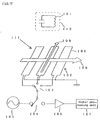
sensor unit 102 has a plate-like sensor surface, a point on which is defined by an X-Y rectangular coordinate. Thesensor unit 102 is formed by arranging many sensor coils 100 side by side in anX-axis direction 108 and a Y-axis direction 109. In Fig. 7, only the sensor coils arranged in the X-axis direction are shown in order to avoid confusion. There are actually a few tens of the sensor coils; however, only three sensor coils are illustrated in the drawing for clarity. - In the position detector 111 which employs the electromagnetic transfer system, electromagnetic waves are transferred between the sensor coils 100 on the
sensor unit 102 and theposition indicator 110 in order to determine the coordinate value of a position specified by the position indicator according to a signal received by the sensor coils 100. Further, the position detector 111 is normally provided also with means for entering the information on the switch of the position indicator or the information on writing pressure in addition to the information on the coordinate value of the position indicator. - Two sets of sensor units are normally provided such that they are orthogonalized in the X-axis direction and the Y-axis direction, respectively, in order to perform coordinate detection in the two directions, namely, the X-axis direction and the Y-axis direction. In this case, it should be noted that "the sensor coils in the X-axis direction" means that they are arranged in the X-axis direction rather than meaning that they are extended in the X-axis direction. As illustrated in Fig. 7, the lengthwise direction of the sensor coils in the X-axis direction agrees with the Y-axis direction.
- The high-frequency signal generator 105 is a well-known circuit for generating an AC signal of a predetermined frequency (e.g. a predetermined value in a range from a few hundreds of kilohertz to a few megahertz). The
receiving circuit 106 is a well-known circuit composed primarily of an amplifier. The signal processing unit 107 is composed primarily of a processor (CPU) and a storage circuit; it carries out XY-coordinate calculation according to the output of thereceiving circuit 106. The processor of the signal processing unit 107 functions to control the coil switching of thecoil selector 103 and the switching of the send/receive selector 104. For the purpose of clarity, the signal lines for controlling thecoil selector 103 and the signal lines for controlling the send/receive selector 104 are omitted in Fig. 7. Thecoil selector 103 may be constituted by a well-known multiplexer. Likewise, the send/receive selector 104 may be constituted by a well-known switching circuit. - The position detecting process in the electromagnetic transfer system will now be described. It is assumed that the foregoing processor of the signal processing unit 107 has set the send/receive selector 104 for the send mode, namely, for the high-frequency signal generator 105, and the processor has set the
coil selector 103 to select one particular sensor coil 100 in a sensor coil group of thesensor unit 102. - A high-frequency signal is issued from the high-frequency signal generator 105 and applied to the selected sensor coil 100 via the send/receive selector 104 and the
coil selector 103. This causes the sensor soil 100 to produce an electromagnetic wave which will be referred to as "transmitter signal." When theposition indicator 110 is placed near the sensor surface under this condition, the resonance circuit 101 in theposition indicator 110 resonates due to the transmitter signal. Then, the processor of the signal processing unit 107 sets the send/receive selector 104 for the receive mode, namely, for thereceiving circuit 106, to stop the issuance of the transmitter signal from the sensor coil 100. In other words, the supply of the high-frequency signal from the high-frequency signal generator 105 is stopped. - Under this condition, the oscillatory phenomenon in the resonance circuit 101 incorporated in the
position indicator 110 is not stopped immediately; damping oscillation continues for a while. Hence, the coil of the resonance circuit 101 generates an electromagnetic wave which will be referred to as "response electromagnetic wave." This response electromagnetic wave is received by the sensor coil 100 (the signal received by the sensor coil 100 at this time will be referred to as "received signal"). The received signal is sent to thereceiving circuit 106, where it is processed, via thecoil selector 103 and the send/receive selector 104. The signal which has been processed by thereceiving circuit 106 is further handed to the signal processing unit 107 which performs XY coordinate calculation and the analysis of switch information according to the amplitude, phase, and so on of the processed signal. The obtained coordinate value and switch information are sent out to a host apparatus not shown, i.e. an external computer. - The resonance circuit 101 built in the
position indicator 110 shown in Fig. 7 is represented as the coil or the resonance circuit 101 because the resonance phenomenon is not necessarily a must as long as magnetic coupling takes place among the sensor coils. - The sending and receiving operation on the foregoing sensor coils 100 is repeated while switching in sequence among the multiple sensor coils 100 on the
sensor unit 102 in a position detecting direction. The operation of switching among the multiple sensor coils 100 in sequence will be referred to as "scanning". - It has already been mentioned that, among the components making up the position detector 111, the
coil selector 103 composed mainly of a multiplexer is primarily responsible for selecting and switching among the multiple sensor coils 100. Also, it has already been mentioned that thecoil selector 103 is connected to the processor of the signal processing unit 107 by a signal line, which is not shown, and it is controlled by the processor. The program describing the operation of the processor is stored in a storage device called a ROM (read-only memory) of the signal processing unit 107 although the storage device, which has not been referred to, is also a component of the position detector. The processor reads in the program stored in the ROM and executes the scanning according to the program. Accordingly, the position detecting process, particularly the scanning method for the sensor coils 100, can be modified by the program stored in the ROM. - The position detecting process will now be described.
- The position detecting process includes the procedure from a point at which no coordinate information (not even an approximate position) on the
position indicator 110 has been obtained to a point at which the detailed coordinate of the position indicator is calculated. As previously mentioned, this process corresponds to the processing contents of the processor of the signal processing unit 107 shown in Fig. 7. From this viewpoint, the position detecting process is not merely the scanning (selecting in a predetermined sequence) the sensor coils 100; instead, it also includes the processing in which the processor of the signal processing unit 107 acquires the output obtained by thereceiving circuit 106 as the result of the selection, the processing for carrying out the coordinate calculation based on the signal level obtained from the previous processing, and the processing for sending out the coordinate value, which has been finally obtained, to external equipment, i.e. a computer which is host equipment in most cases. - The processing for obtaining the output signal of the
receiving circuit 106 is implemented immediately after every scan of each of the sensor coils 100. The coordinate calculation processing is implemented immediately after the receiving levels (the voltage levels of the transmitter signals of the receiving circuit 106) at a plurality of (about 2 to about 4) sensor coils located in the vicinity of theposition indicator 110 have been obtained. As a specific method for the coordinate calculation, 2-point technique or 3-point technique (quadric function approximation) is known. The coordinate value sending-out processing is implemented upon completion of the coordinate calculation; the obtained coordinate value is sent out to external equipment by using a well-known interface circuit such as a means which conforms to the RS-232C standard. - Herein, considering that the present invention is related mainly to the scanning method or the scanning sequence of the sensor coils, the description will be focused on the scanning procedure of the sensor coils 100, abstracting the procedure for obtaining the output of the
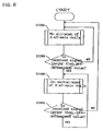
receiving circuit 106, the coordinate calculation processing, and the processing for sending out the coordinate value. - Figure 8 shows a flowchart illustrative of the position detecting process in a conventional electromagnetic transfer system. As illustrated in Fig. 8, the process for detecting a position of the position indicator may be roughly divided into all-scan process and sector-scan process. The term "all-scan" means to scan the sensor coils all over the area of the sensor coil surface, i.e. the surface on which the X- and Y-axis sensor coils are provided side by side. All-scan does not always refer to a case where all sensor coils are scanned; it may refer to a case where, for example, every other sensor coils are scanned. In the flowchart, only "scan" is shown for the purpose of simplicity; the actual scanning operation, however, includes a plurality of steps. For this reason, the boxes with double-line sides are used for steps ST200 and ST400 of Fig. 8. In the actual operation, every time each sensor coil 100 is scanned, the control step for switching the send/receive selector 104 and the processing step for acquiring the transmitter signal of the
receiving circuit 106 are carried out. - The processing for detecting a position indicator starts with the all-scan process (step ST200). The all-scan process is implemented on both X-axis and Y-axis. This all-scan may be regarded as rough detection because it is intended mainly for quickly obtaining the approximate position of the
position indicator 110. - At the completion of the all-scan process, the processor will have obtained the signal intensity distribution of the received signals on the sensor unit according to the signals received from the sensor coils 100. This is illustrated in Fig. 9. The nearly square member in Fig. 9 represents the
sensor unit 102. The thick arrows crossing on thesensor unit 102 indicate the coil selecting directions of the X-axis and Y-axis. As shown in Fig. 9, it is assumed that theposition indicator 110 is pointing at a certain position on thesensor unit 102. The signal intensity distribution obtained by the processor upon completion of the all-scan process is shown by the bar graph shown in Fig. 9. The bar graph shows only the intensity distribution obtained by the scan in the X-axis direction. As indicated by the bar graph, when theposition indicator 110 is located near the sensor surface, the intensity of the received signal of the sensor coil closest to theposition indicator 110 shows the highest value. Hence, the group of several sensor coils around the sensor coil giving the highest value shows the peak of the signal intensity distribution. This makes it possible to know the approximate position. - Figure 9 shows a constant level of signal intensity in the area other than the group of several sensor coils around the sensor coil giving the highest value. Such a constant level of signal intensity is sometimes called as an offset value because there is a certain level of output even when no input is applied to the receiving
circuit 106 in Fig. 7. - The program determines in step ST299 whether the signal intensity of the received signal shown in Fig. 9 is larger than a predetermined value; if it is smaller than predetermined value, then the program goes back to the all-scan step ST200, or if it is larger than the predetermined value, then the program moves onto the sector-scan step ST400. The predetermined value is a "threshold value" which is a preset appropriate value above the offset value mentioned above.
- In the sector-scan step ST400, the foregoing sending and receiving operation is repeated using the sensor coil at the central position and several sensor coils adjacent thereto obtained as the result of the all-scan step. As shown by the coil selecting area in Fig. 10, the sector-scan step ST400 is carried out at least on the X-axis and the Y-axis. This allows the detailed signal intensity distribution to be obtained as shown in Fig. 10; the coordinate value is determined by performing the interpolative calculation of the respective received signals in the signal processing unit 107 shown in Fig. 7. Thus, the sector-scan is a more detailed detection process.
- The term "more detailed "means" more detailed in both time-wise and space-wise. More specifically, "more detailed in time" comes from the fact that the time required for the sector-scan is shorter than that required for the all-scan. For instance, if all-scan takes five times as long as the sector-scan takes, then it means that five coordinate values can be obtained by the sector-scan in the same time as that for the all-scan to obtain one coordinate value. This characteristic contributes to good trackability primarily in the dynamic characteristic of the position detector, especially when the position indicator moves quickly.
- The situation of the "more detailed space-wise" may occur when skipping scan is carried out in the all-scan step (the all-scan can include the skipping scan as previously mentioned), whereas no skipping is made in the sector-scan step. This is a problem with the spatial gaps of the sensor coils used; therefore, the spatial detailedness contributes to the resolution or accuracy of the obtained coordinate value.
- As shown in Fig. 8, when the position detector 111 is initially started up, the program performs the all-scan in step ST200, and when the approximate position of the
position indicator 110 is found, the program gives an affirmative determination result (YES) in step ST299 and proceeds to the sector-scan in ST400. If no approximate position is found, then the program gives a negative determination result (NO) in step ST299 and repeats the all-scan in step ST200 thereafter. The affirmative determination result (YES) is given in step ST499 as long as the coordinate of theposition indicator 110 is obtained by the sector-scan; hence, the sector-scan is repeated. If theposition indicator 110 is missed during the sector-scan, then the program gives the negative determination result (NO) in step ST499, so that it goes back to the all-scan in ST200. Thus, the two different scanning methods, namely, the all-scan and the sector-scan, are combined to accomplish efficient coordinate detection. - An example of the method for detecting a plurality of position indicators will now be described.
- The method for detecting a single position indicator is called "single-scan"; the method for detecting a plurality of position indicators is called "multi-scan".
- The same number of resonance circuits of different resonance frequencies as the number of position indicators to be detected are prepared, and all the position indicators are provided with the prepared resonance circuits. A position detector performs sending and receiving at particular frequencies for the position indicators and it carries out all-scan or sector-scan for the respective resonance frequencies alternately so as to detect the multiple position indicators.
- To multi-scan two indicators, two position indicators which have different, fixed resonance frequencies are prepared to enable a position detector to communicate with the position indicators by using the different frequencies. In this case, one of the following different scanning processes is selectively implemented: in a first process, all-scan is carried out for two different frequencies alternately; in a second process, two types of scanning are alternately carried out, namely, sector-scan for one frequency and all-scan for the other frequency; and in a third process, the sector-scan is carried out for the two frequencies alternately.
- The description given above is based on the assumption that the electromagnetic transfer system is employed. There are, however, other position detecting systems. As a simple electromagnetic system, there is one in which electromagnetic waves are transmitted from a sensor surface and received by a position indicator, or electromagnetic waves are transmitted from the position indicator and received by the sensor surface. There is a cross type detection system in which a sensor coil in the X-axis direction transmits a signal and a sensor coil in the Y-axis direction receives it. There is also a self-oscillation type detection system disclosed in Japanese Unexamined Patent publication No. 5-241722.
- Thus, all the systems described above have, in common, a plurality of coils arranged side by side in the X and Y directions to scan the coils so as to perform coordinate detection. For this reason, all the systems are facing the task of achieving efficient scanning to detect a plurality of position indicators.
- There has been, however, a problem with the multi-scan for detecting the positions of a plurality of position indicators at the same time. To be more specific, detecting the positions of the position indicators requires that the sensor coils of the position detector be scanned alternately for the same number of times as the number of the position indicators. In comparison with the single-scan for detecting the position of only one position indicator, the multi-scan avoidably exhibits deteriorated performance in the trackability of coordinate values in relation to the actual positions of the position indicators when the position indicators are moved, or a deteriorated dynamic characteristic which is the performance involved in relatively quick moving of position indicators.
- Normally, the trackability of the multi-scan for detecting two position indicators is reduced simply to a half of that of the single-scan for detecting only one position indicator, thus leading to deterioration in performance of the multi-scan.
- More specifically, in the case of the multi-scan for detecting at least two position indicators, the sensor coils of the position detector are scanned alternately to detect the position indicators. This has resulted in slower recognition of the position indicators.
- Accordingly, it is a chief object of the present invention to improve trackability in detecting a plurality of position indicators.
- It is another object of the present invention to provide further practical trackability according to the position indicator used, by making it possible to set or change scan repeating frequency and so on according to the type of the like of the position indicator.
- To this end, according the present invention, there are provided: a first detection process for detecting an approximate position of a first position indicator by an all-scan step for detecting the approximate position of the position indicator on a coordinate reading surface by extensively scanning many sensor coils along coordinate axes; and a second detection process in which, if it has been determined that the first position indicator is present on the coordinate reading surface in the first detection process, then a sector-scan step for performing more detailed detection of the position of the first position indicator by specifying the sensor coils to be scanned in accordance with the positional information of the first position indicator which has been detected by the first detection process, and an all-scan step for detecting the approximate position of a second position indicator are implemented alternately; wherein the sector-scan step is implemented at a higher repeating frequency than the all-scan step in the second detection process.
- If it has been detected that the first position indicator is present on the coordinate reading surface by the all-scan in the first detection process, then a program moves onto a second detection process. In the second detection process, the sensor coils are specified and scanned according to the positional information on the first position indicator so as to alternately carry out the sector-scan step for performing more detailed detection of the position of the first position indicator and the all-scan step for detecting the approximate position of the second position indicator. To alternately carry out the two types of scans, the sector-scan is implemented more frequently than the all-scan.
- Thus, the second position indicator can be detected with a minimum sacrifice in the trackability of the first position indicator.
- Further, according to the invention, the repeating frequency, etc. of the all-scan step or the sector-scan step can be set or changed according to the type or the like of the position indicator.
- Hence, further practical trackability can be achieved for the type of position indicator used.
-
- Fig. 1 is a block diagram showing an embodiment of the invention;
- Fig. 2 is a flowchart for illustrating the operation of the embodiment;
- Fig. 3 is another flowchart for illustrating the operation of the embodiment;
- Fig. 4 is a schematic block diagram of the embodiment;
- Fig. 5 is a flowchart for illustrating the operation of another embodiment;
- Fig. 6 is a flowchart for illustrating the operation of still another embodiment;
- Fig. 7 is a block diagram for illustrating the basic operation of a position detector which employs a conventional electromagnetic transfer system;
- Fig. 8 is a flowchart showing the position detecting process in the conventional electromagnetic transfer system;
- Fig. 9 is a schematic block diagram for illustrating the basic operation of the position detector which employs the conventional electromagnetic transfer system; and
- Fig. 10 is a schematic block diagram for illustrating the basic operation of the position detector which employs the conventional electromagnetic transfer system.
-
- An embodiment of the present invention will now be described in conjunction with the accompanying drawings.
- Fig. 1 is the block diagram of a position detector of the embodiment in accordance with the present invention. Although it is not shown in Fig. 1, a
sensor unit 1 is composed by forty loop coils disposed in parallel to the X-axis and forty loop coils disposed in parallel to the Y-axis, thus forming a coordinate reading surface. The respective loop coils constitute sensor coils connected to aselector circuit 2 for selecting the loop coils. Theselector circuit 2 is connected to a send/receiveselector circuit 3; anamplifier 5 is connected to the receiving end of the send/receiveselector circuit 3, and the output end of theamplifier 5 is connected to asignal processing unit 6. Thesignal processing unit 6 is constructed by a central processing unit (CPU), a read-only memory (ROM), etc. The output end of acurrent driver 11 is connected to the sending end of the send/receiveselector circuit 3; afrequency selector switch 12 is connected to the input end of thecurrent driver 11; andoscillators 13 and 14 which have different frequencies are connected to thefrequency selector switch 12. Thefrequency selector switch 12 is switched in response to a control signal received from the CPU in thesignal processing unit 6; it sets the frequency of a signal transmitted from each loop coil to f0 or f1. The frequency f0 is preset so that it is equal to the resonance frequency of a first position indicator which will be discussed later, while the frequency f1 is present so that it is equal to the resonance frequency of a second position indicator which will be discussed later. Other control signals are supplied from the CPU in thesignal processing unit 6 to theselector circuit 2 and the send/receiveselector circuit 3 so as to scan the sensor coils or select between the send mode and the receive mode. Theselector circuit 2 together with thesignal processing unit 6 make up the selecting means for selectively scanning the sensor coils; they select the sensor coils in sequence to selectively scan or select a particular area or a particular number of sensor coils to scan in the all-scan mode and the sector-scan mode. - A
position indicator 8 includes: aresonance circuit 201 composed of a coil and a capacitor; aROM 203 wherein the shape or usage of the position indicator, the description of the information that can be provided, or the information on a particular identification (ID) of the position indicator is stored; and acontrol circuit 202 which mainly carries out the control for reading the contents stored in theROM 203 and supplying them to theresonance circuit 201. Regarding theposition indicator 8, only the section related to the invention is shown in a simplified manner. Theposition indicator 8 does not necessarily include the resonance circuit; it may alternatively include only the coil as long as it can be magnetically coupled with thesensor unit 1 to send and receive signals. - To simplify the description hereinafter, the description of switching the sensor coils in sequence, which is performed in actual operation, will be omitted; the switching of the sensor coils will be referred to simply as "scanning step". In the following description, both X-axis and Y-axis will be scanned at the same time in one process; however, either the X-axis or the Y-axis may be separately scanned.
- The embodiment will be described in conjunction with the state diagrams of Fig. 4 which shows the relationship between the position detector and the position indicator in time series.
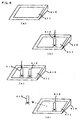
- In Fig. 4, a
position detector 410 is provided with aninput surface 411. Theinput surface 411 is a sensor coil in the circuit and hence it is also referred to as thesensor surface 411. The position indicator shown in Fig. 4 is a pen type indicator "stylus pen"; however, since the present invention applies to any type of position indicator, it is called simply as "position indicator". In a state (a) wherein the all-scan step is implemented, no position indicator is placed on thesensor surface 411. - When a
first position indicator 412 having a resonance circuit of the resonance frequency f0 is placed on thesensor surface 411, a state (b) is set for carrying out the sector-scan step on thefirst position indicator 412. Then, when a second position indicator 413 having a resonance circuit of the resonance frequency f1 is placed on thesensor surface 411, a state (c) is set for carrying out the sector-scan step on the first andsecond position indicators 412 and 413, respectively. Further, when the second position indicator 413 moves away from thesensor surface 411 so that theposition detector 410 can no longer detect the second position indicator 413, a state (d) is set, wherein the sector-scan step is implemented for detecting thefirst position indicator 412 and the all-scan step is implemented for detecting the second position indicator 413. In the state (d), the second position indicator 413 is rendered undetectable as an example; however, thefirst position indicator 412 may alternatively be rendered undetectable. - Figures 2, 3, and 5 show flowcharts illustrative of the operation of the
signal processing unit 6 of Fig. 1. The embodiment will be described by referring to Fig. 1 to Fig. 5. - In the states (a) and (b) of Fig. 4, the
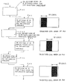
position detector 410 first carries out an all-scan step ST01 on thefirst position indicator 412 at the frequency f0 in process P0 and process (1) in Fig. 2. It is determined in step ST02 whether a received signal is larger than a predetermined value; if it is determined that the received signal is larger than the predetermined value, i.e. if detection is enabled, then theposition detector 410 moves onto a sector-scan step ST03. - Process (2) which combines process P1 and process P2 will now be described. In step ST04, it is determined whether the received signal which has been subjected to the sector-scan step ST03 is larger than the predetermined value; if it is determined that the received signal is smaller than the predetermined value, then the program returns to step ST01. If it is determined that the received signal is larger than the predetermined value, then the number of scans is first incremented and moves to ST05 wherein it is determined whether a predetermined number of scans has been satisfied. If the predetermined number of scans has not been satisfied, then steps ST03 and ST04 are repeated. If the predetermined number of scans is satisfied, then all-scan step ST06 for detecting the second position indicator 413 is carried out at the frequency f1. Then, it is determined in step ST07 whether the received signal is larger than the predetermined value; if it is judged that the received signal is less than the predetermined value, then the program returns to step ST03, or if it is judged that the received signal is larger than the predetermined value, then the program proceeds to step ST08.
- In process (2), the all-scan for detecting the second position indicator 413 is continued although the all-scan step for detecting the second position indicator 413 is implemented at a lower repeating frequency than that of the sector-scan step for detecting the
first position indicator 412. More specifically, the repeating frequency of the all-scan step for detecting the second position indicator 413 is lower than the repeating frequency of the sector-scan step for detecting thefirst position indicator 412, and these are alternately repeated. - An example of the scanning repeating frequency mentioned above will be described. The ratio of the numbers of repetitions of the
first position indicator 412 to the second position indicator 413 is set to 4:1. In this case, the predetermined number of repetitions in step ST05 is set to 4. This means that detection process P1 wherein thefirst position indicator 412 is detected for four times in succession is carried out, then detection process P2 wherein the second position indicator 413 is detected once is carried out; the respective detection processes P1 and P2 are implemented alternately. This enables the detecting operation to be performed with minimized sacrifice in the trackability of thefirst position indicator 412. - Irregular scanning may affect the coordinate moving intervals; however, this problem may be alleviated by carrying out coordinate travel averaging processing or a method for predicting a coordinate travel.
- The scan repeating frequency can be changed as desired by a user according to the size of the effective area of the position detector or the application in which the position detector is used. For instance, there is a method wherein a means for communicating with a host computer connected to the
signal processing unit 6 of the position detector shown in Fig. 1 is employed to enable thesignal processing unit 6 to receive an instruction signal, which is transmitted via the communication means from the host computer, through a receiving means so as to change the setting of the repeating frequency according to the type of the instruction signal. - A control unit such as a push-button switch or a rotary switch may be connected to the
signal processing unit 6 to enable the signal processing unit to detect the operating amount of the control unit, namely, the number of pushes on the switch, the rotary angle, or the like, thereby making it possible to set or change the repeating frequency. Such a set value which has been established or updated may be stored in an involatile storage device or the like such as an EEPROM or a flash memory which permits electrical writing and erasing. Reading in the new set value each time the power of the position detector is turned ON eliminates the need for instructing every new set value. - Process (1) corresponds to the first detection process, while process (2) corresponds to the second detection process in the position detecting method.
- Process (1) constitutes the first detecting means, while process (2) constitutes the second detecting means in a
position detector 7. - In the state (c) of Fig. 4, the program proceeds from process (2) to process (3).
- In process (3), sector-scan step ST08 is implemented for detecting the
first position indicator 412; and in step ST09, it is determined whether the received signal is larger than a predetermined value. If it is determined that the received signal is larger than the predetermined value, then sector-scan step ST10 for detecting the second position indicator 413 is carried out. In step ST11, it is determined whether the received signal is larger than the predetermined value; if it is larger than the predetermined value, then the program goes back to step ST08. - Process (3) shows the state wherein the sector-scan step is being implemented alternately on the
first position indicator 412 and the second position indicator 413 which have been detected. In process (3), the scan repeating frequencies for the first andsecond position indicators 412 and 413, respectively, are set equally to 1:1. More specifically, thefirst position indicator 412 is sector-scanned for a predetermined number of times, then the second position indicator 413 is sector-scanned for a predetermined number of times. When repeating the sector-scanning of the two position indicators alternately, the same number of times is set for carrying out the sector-scan of theposition indicators 412 and 413. This is effective for providing equal trackability while the two position indicators are being detected. Process (3) corresponds to a third detection process in the position detecting method. - A state (d) of Fig. 4 will now be described.
- If it is determined that the received signal of sector-scan step ST10 for detecting the second position indicator 413 is smaller than the predetermined value in step ST11, then the program moves onto step ST14 (ST21) of Fig. 3 where process (4) is implemented.
- In process (4), sector-scan step ST21 for detecting the
first position indicator 412 is carried out, then it is determined in step ST22 whether the received signal is larger than the predetermined value. If the received signal is larger than the predetermined value, then all-scan step ST23 for detecting the second position indicator 413 is implemented, and it is determined in step ST24 whether the received signal is larger than the predetermined value. If it is determined in step ST24 that the received signal is smaller than the predetermined value, then the program proceeds to step ST25 wherein it decides whether a predetermined time has elapsed; if the predetermined time has not elapsed, then the program returns to step ST21, or it proceeds to step ST12 if the predetermined time has elapsed. - In process (4), if it is determined that either the
position indicator 412 or 413 is invalid while the sector-scan is being carried out on thefirst position indicator 412 and the second position indicator 413 which have been detected, and the program returns to the all-scan step, then the scan repeating frequency for thefirst position indicator 412 and the second position indicator 413 is maintained to 1:1 for the foregoing predetermined time. After the predetermined time has passed, the position indicator subjected to the all-scan step is scanned at a lower repeating frequency than that for the position indicator subjected to the sector-scan step; the two types of scans are alternately repeated as described above. Process (4) corresponds to a fourth detection process in the position detecting method. - There are two possible cases where the position indicators are rendered invalid. In one case, the position indicator is no longer necessary and the operator places the position indicator in an area out of the sensor surface, i.e. out of the effective zone, of the position detector. In the other case, the position indicator is temporarily in an invalid state in an undetectable area while it is still held in a hand of the operator. The latter case often happens in normal operation. Hence, it is appropriate to maintain the scan repeating frequency at 1:1 within a certain time because it would take more time to recognize the position indicator if the program goes back to process (2) immediately after the all-scan step is started on the position indicator.
- There are two methods to set the above certain time or predetermined time: in one method, the time may be set, for example, to 1 minute; and in the other method, one process of the all-scan or sector-scan may be regarded as 1 count, and the certain time may be set as 10,000 counts.
- There is also a different method whereby the repeating frequency is gradually changed within a certain time. For instance, when the ratio of the detection repeating frequency of the
first position indicator 412 and the detection repeating frequency of the second position indicator 413 are set to 4:1, the repeating frequency is 1:1 in the state of sector-scan step process (3) (state (c) of Fig. 4) in which both thefirst position indicator 412 and the second position indicator 413 are being detected; when the second position indicator 413 is placed in the invalid state (state (d) of Fig. 4), the program returns to the all-scan step for detecting the second position indicator 413. At this time, the repeating frequency within 1 minute will be as follows: the ratio of the process for thefirst position indicator 412 to the process for the second position indicator 413 equals 1:1. When 1 minute has elapsed, a repeating frequency of 2:1 is applied. When another 1 minute has elapsed, a repeating frequency of 3:1 is applied. When yet another 1 minute has elapsed, the repeating frequency of 4:1 is applied. Thus, the scan repeating frequency is gradually changed as time passes. - The foregoing set predetermined time may be changed as desired according to the size of the effective area of the position detector or the application in which the position detector is used. As the setting method, the one described in conjunction with process (2) may be employed.
- Another embodiment related to the all-scan step will now be described.
- In a position detector adapted to detect a plurality of position indicators by their different resonance frequencies, the position indicators have resonance frequencies which are set according to the shapes thereof. For example, a pen type position indicator has a first resonance frequency, while a cursor type position indicator has a second resonance frequency. In this case, in the state (a) of Fig. 4, the pen type position indicator and the cursor position indicator are not located on the sensor surface, and the all-scan step is being implemented on the two types of position indicators alternately.
- In this case, process (5) shown in Fig. 5 is carried out. First, the all-scan step for detecting the pen type position indicator of the first resonance frequency is carried out in step ST31, then it is determined in step ST32 whether the received signal is larger than a predetermined value; if it is smaller than the predetermined value, then the counter is incremented in step ST34. In the following step ST35, it is determined whether the value on the counter is identical to the predetermined value (the predetermined value in this embodiment is "4"), and if it is smaller than the predetermined value, then the program goes to step ST31; or if it is identical to the predetermined value, then the predetermined value is initialized before moving onto all-scan step ST36 for detecting the cursor type position indicator. In step ST37, it is determined whether the received signal is larger than the predetermined value; if it is smaller than the predetermined value, then the program goes back to step ST31. Although it is not shown, if the pen type position indicator or the cursor type position indicator becomes undetectable and invalid after the program proceeds to the sector-scan in step ST33 or ST38, then the program moves onto a step for carrying out the all-scan.
- In process (5), the all-scan step for detecting the position indicator for which the recognizing time need to be shortened is repeatedly implemented more frequently than that for detecting the other position indicator. The all-scan step is repeated on these two position indicators alternately.
- It is known that, the pen type position indicator, for example, is moved up and down frequently on the sensor surface, causing the valid and invalid processing to be switched frequently. Hence, the position indicator is required to be recognized quickly. In contrast to this, the cursor type position indicator is placed mostly in the effective area of the position detector, so that the recognizing speed is not as important as in the case of the pen type. In this embodiment, when the resonance frequencies are set for the pen type position indicator and the cursor type position indicator, respectively, and the position detector scans for those resonance frequencies alternately, the all-scan step for the pen type position indicator is implemented at a higher repeating frequency than that for the cursor type position indicator so as to achieve time-efficient recognition of the position indicators by their shapes. Process (5) corresponds to a fifth detection process in the position detecting method. Also, process (5) constitutes a third detecting means in the
position detector 7. - Another embodiment related to the all-scan step will be described with reference to Fig. 6. Figure 6 corresponds to the state (b) in Fig. 4; it is characterized in that the scan is limited to small areas rather than setting the scan repeating frequencies. In Fig. 6, only the characteristic portion of the all-scan step in this embodiment is shown.
- In the state (b) of Fig. 4, the
first position indicator 412 is placed on thesensor surface 411, and the sector-scan step for detecting thefirst position indicator 412 and the all-scan step for detecting the second position indicator 413 are carried out alternately. At this time, the ratio of the repeating frequency of the sector-scan step to that of the all-scan step is set to 1:1. - First, sector-scan process P40 for detecting the
first position indicator 412 is carried out. Process P40 corresponds to step ST03 and step ST04 of Fig. 2. Next, all-scan process P41 for detecting the second position indicator 413 is carried out. Process P41 corresponds to step ST06 and step ST07 of Fig. 2. As shown in Fig. 6, in this state, the two processes are implemented basically alternately; however, in process P41, if there are, for example, thirty X-axis sensor coils of theposition detector 410, then ten sensor coils in the left area are subjected to the all-scan, for example, in the X-axis direction in this process. Likewise, the ten sensor coils in the central area are subjected to the all-scan in process P43, and the ten sensor coils in the right area are subjected to the all-scan in process P45. In this embodiment, the entire sensor surface is all-scanned in the three processes. - Thus, in this embodiment, the number of coils to be scanned per process is reduced and the entire sensor surface is divided into a few areas to scan it in a few processes when carrying out the all-scan step.
- The embodiment described above may be summarized as shown below:
- (1) The first indicator is subjected to the sector-scan, while the second indicator is subjected to the all-scan of ten sensor coils in the left area.
- (2) The first indicator is subjected to the sector-scan, while the second indicator is subjected to the all-scan of ten sensor coils in the central area.
- (3) The first indicator is subjected to the sector-scan, while the second indicator is subjected to the all-scan of ten sensor coils in the right area.
-
- This method completes the scanning process in one third of the time required when performing the all-scan over the entire sensor surface, providing an advantage in that the deterioration in the trackability of the sector-scan can be controlled.
- The process shown in Fig. 6 constitutes a fourth detecting means in the
position detector 7. - The set number of coils to be scanned may be changed as desired according to the size of the effective area of the position detector or the application in which the position detector is used. As the setting method, the one described above may be employed.
- The small areas to be scanned and the numbers of the coils are set in advance and a plurality of scanning patterns of small areas or the number of sensor coils to be selected are prepared beforehand, the scanning patterns being stored in a data table. In the all-scan step, the pointer is incremented upon completion of one process, and the data table of the scanning patterns is referred to in sequence according to the pointer. Scanning based on the scanning area or selected sensor coils according to the referred contents enables more sophisticated selecting method to be employed. For instance, a position indicator is usually placed at the center of the sensor surface at the beginning. Setting the scanning pattern such that the central area is scanned at a high frequency as a whole makes the operator feel that the position indicator is recognized more quickly in actual operation.
- The following describes an example of the method for identifying the types of position indicators.
- The position indicators are provided with means for sending the information on the shape or usage of the position indicator, the information which can be provided, or the information on a particular identification (ID) to the position detector in the form of signals. As a simple means for this purpose, the differences of the position indicators are indicated by phase information in advance, so that the position detector may identify the position indicators by detecting the phases thereof.
- Further, as shown in Fig. 1, the
position indicator 8 may be provided with acontrol circuit 202 composed of an IC circuit, and theROM 203 for storing binary ID codes to provide a means for allowing digital information, i.e. ID information, to be transmitted to theposition detector 7. The ID code at this time is binary ID data which provides the information on the shape or usage of theposition indicator 8, the information that can be supplied, or the information on a particular ID. In brief, thecontrol circuit 202 of theposition indicator 8 is equipped with an IC circuit capable of receiving, through a resonance circuit, a signal sent from the sensor coils of theposition detector 7 and of counting the receiving time of the signal. Theposition detector 7 is equipped with a means for changing the sending time of a transmitter signal and a setting means therefor. A relatively long transmitter signal is sent from theposition detector 7 to theposition indicator 8. Theposition indicator 8 receives the signal and reads a binary ID code from theROM 203 of theposition indicator 8 through thecontrol circuit 202; at predetermined time intervals, the transmitter signal is sent to theposition indicator 7 if the ID code "1", whereas no transmitter signal is sent if the ID code is "0". Theposition detector 7 receives the signals and judges the information on the shape or usage of theposition indicator 8, the information that can be supplied, or the information on a particular ID. - Using the means described above makes it possible to detect the information on the shape or usage of the
position indicator 8, the information that can be supplied, or the information on a particular ID. - The operator will be able to operate the position detector with optimum set values without worrying about setting details by using the detecting means in combination with the means for changing the setting of the scan repeating frequency, the number of coils or areas to be scanned, predetermined time, etc. which have been preset according to the information on the shape or usage of the
position indicator 8, the information that can be supplied, or the information on a particular ID. - In the embodiments described above, only two position indicators have been detected; the invention, however, is applicable also to more than two position indicators.
- The examples of the electromagnetic transfer type position detectors have been described; the present intention, however, can be easily applied to any type of position detector as long as it is a position detector which is adapted to detect a plurality of position indicators and which employs a method for selecting and scanning sensor coils.
- Further in the above embodiments, the resonance frequencies for the position indicators have been fixed; however, they may be configured to permit switching among a plurality of different frequencies.
- Thus, according to the present invention, when detecting a plurality of position indicators, the sector-scan step for detecting the first position indicator is implemented more frequently than the all-scan step for detecting the second position indicator; the sector-scan step and the all-scan step are alternately implemented repeatedly, thus permitting improved trackability.
- Moreover, improved trackability of the position indicators can be achieved further effectively by employing the method wherein the same repeating frequency is applied to both types of scan when a plurality of position indicators have been detected, then the same repeating frequency is used for a predetermined time if one of the position indicators is found invalid and all-scan is initiated, or the method for limiting the areas to be scanned.
- In the all-can step, the scanning of the position indicator which need to be recognized quickly is repeated more frequently than that of the other position indicator so as to enable quicker recognition.
- Furthermore, the repeating frequency and the like are set according to the information on the shapes or usages of the position indicators, the information that the position indicators have, the information on particular IDs, or other information. This makes it possible to set the repeating frequency and so on suited for the position indicators, permitting higher efficiency in practical use.
Claims (17)
- A position detecting method for detecting a plurality of position indicators, wherein a position detector including a sensor unit which has many sensor coils arranged in parallel in the directions of coordinate axes to form a coordinate reading surface, and selecting means for selectively scanning said sensor coils, and a plurality of position indicators incorporating at least coils are used in order to detect the coordinate values of said position indicators on said coordinate reading surface according to the detection signals obtained from the interaction between said sensor coils and said position indicators;said position detecting method comprising:a first detection process for detecting an approximate position of a first position indicator by an all-scan step for detecting the approximate positions of said position indicators on said coordinate reading surface by extensively scanning said multiple sensor coils along said coordinate axes; anda second detection process in which, if it has been determined that said first position indicator is present on said coordinate reading surface in said first detection process, then a sector-scan step for performing more detailed detection of the position of said first position indicator by specifying said sensor coils to be scanned in accordance with the positional information on said first position indicator which has been detected by said first detection process, and an all-scan step for detecting the approximate position of a second position indicator are implemented alternately;
wherein said sector-scan step is implemented at higher repeating frequency than said all-scan step in said second detection process. - A position detecting method for detecting a plurality of position indicators according to Claim 1, wherein, if it has been determined that said second position indicator is present on said coordinate reading surface in said second detection process, then a program moves onto a third detection process in which the sector-scan step for detecting said first and second position indicators is implemented alternately on said two position indicators at the same repeating frequency.
- A position detecting method for detecting a plurality of position indicators according to Claim 1 or 2, wherein, if either position indicator has not been detected and has been determined as invalid in said third detection process and the program moves onto the all-scan step, then the program proceeds to a fourth detection process in which the all-scan step for detecting said position indicator which has been determined as invalid and the sector-scan step for detecting a position indicator for which the detection is being continued are alternately implemented at the same repeating frequency for a predetermined time, and after said predetermined time has elapsed, the program moves onto said second detection process.
- A position detecting method for detecting a plurality of position indicators according to Claim 3, wherein, after said predetermined time has elapsed, the program moves from said fourth detection process to said second detection process while changing said repeating frequency in steps with time.
- A position detecting method for detecting a plurality of position indicators according to Claim 3 or 4, wherein said predetermined time can be set or changed.
- A position detecting method for detecting a plurality of position indicators, wherein a position detector including a sensor unit which has many sensor coils arranged in parallel in the directions of coordinate axes to form a coordinate reading surface, and selecting means for selectively scanning said sensor coils, and a plurality of position indicators incorporating at least coils are used in order to detect the coordinate values of said position indicators on said coordinate reading surface according to the detection signals obtained from the interaction between said sensor coils and said position indicators;said position detecting method comprising:a fifth detection process wherein signals of at least two different frequencies are employed to implement an all-scan step at said different frequencies alternately so as to detect the approximate positions of at least two position indicators which respond respectively to said different frequencies;
wherein said all-scan step for detecting one position indicator for which trackability need to be further improved is carried out at a higher repeating frequency than the all-scan step for detecting the other position indicator in said fifth detection process. - A position detecting method for detecting a plurality of position indicators according to Claim 1, 2, 3, or 6, wherein said repeating frequency can be set or changed.
- A position detecting method for detecting a plurality of position indicators according to Claim 1, 2, 3, 6, or 7, wherein a plurality of scans of small areas are combined to provide an extensive all-scan in carrying out said all-scan step for detecting a position indicator for which said repeating frequency should be low.
- A position detecting method for detecting a plurality of position indicators according to Claim 8, wherein said small scan areas in said all-scan step can be set or changed by specifying small scan areas or by specifying the number of sensor coils to be scanned.
- A position detecting method for detecting a plurality of position indicators according to Claim 8, wherein: a plurality of scanning patterns of said small scan areas or sensor coils to be selected are prepared and stored in a data table; said scanning pattern data table is referred to in sequence for each process when implementing said all-scan step; and said scan areas or selected sensor coils based on the contents referred to are scanned.
- A position detecting method for detecting a plurality of position indicators according to Claim 1 or 6, wherein:said position indicators are provided with means for sending the information on the shapes or usages thereof, the description of the information which can be provided, or the information on particular IDs to a position detector in the form of signals, while said position detector is provided with detecting means for detecting said signals;said position indicators send the information on the shapes or usages thereof, the description of the information which can be provided, or the information on particular IDs in the form of signals according to the scan of said sensor coils; andsaid position detector receives said signals and changes said repeating frequency to a suitable set value according to the information on the shapes or usages of the position indicators, the description of the information which can be provided, or the information on particular IDs obtained from said signals.
- A position detecting method for detecting a plurality of position indicators according to Claim 3, 4, or 5, wherein:said position indicators are provided with means for sending the information on the shapes or usages thereof, the description of the information which can be provided, or the information on particular IDs to a position detector in the form of signals, while said position detector is provided with detecting means for detecting said signals;said position indicators send the information on the shapes or usages thereof, the description of the information which can be provided, or the information on particular IDs in the form of signals according to the scan of said sensor coils; andsaid position detector receives said signals and changes said predetermined time to a suitable set value according to the information on the shapes or usages of the position indicators, the description of the information which can be provided, or the information on particular IDs obtained from said signals.
- A position detecting method for detecting a plurality of position indicators according to Claim 8, 9, or 10, wherein:said position indicators are provided with means for sending the information on the shapes or usages thereof, the description of the information which can be provided, or the information on particular IDs to a position detector in the form of signals, while said position detector is provided with detecting means for detecting said signals;said position indicators send the information on the shapes or usages thereof, the description of the information which can be provided, or the information on particular IDs in the form of signals according to the scan of said sensor coils; andsaid position detector receives said signals and changes said small scan areas or said number of sensor coils to be scanned to a suitable set value according to the information on the shapes or usages of the position indicators, the description of the information which can be provided, or the information on particular IDs obtained from said signals.
- A position detecting method for detecting a plurality of position indicators according to Claim 11, 12, or 13, wherein said repeating frequency, said predetermined time, said small scan areas, and said number of sensor coils to be scanned may be set or changed for each type of said position indicators.
- A position detector for detecting a plurality of position indicators, said position detector including a sensor unit which has many sensor coils arranged in parallel in the directions of coordinate axes to form a coordinate reading surface, and selecting means for selectively scanning said sensor coils; wherein the coordinate values of said position indicators on said coordinate reading surface are detected according to the detection signals obtained from the interaction between a plurality of position indicators, which incorporates at least coils, and said sensor coils;said position detector comprising:first detecting means for detecting an approximate position of a first position indicator by an all-scan step for detecting the approximate positions of said position indicators on said coordinate reading surface by extensively scanning said multiple sensor coils along said coordinate axes; andsecond detecting means which, if it has been determined that said first position indicator is present on said coordinate reading surface by said first detecting means, alternately carries out a sector-scan step for performing more detailed detection of the position of said first position indicator by specifying said sensor coils to be scanned in accordance with the positional information of said first position indicator which has been detected by said first detecting means, and an all-scan step for detecting the approximate position of a second position indicator;
wherein said second detecting means carries out said sector-scan step at a higher repeating frequency than said all-scan step. - A position detector for detecting a plurality of position indicators, said position detector including a sensor unit which has many sensor coils arranged in parallel in the directions of coordinate axes to form a coordinate reading surface, and selecting means for selectively scanning said sensor coils; wherein the coordinate values of said position indicators on said coordinate reading surface are detected according to the detection signals obtained from the interaction between a plurality of position indicators, which incorporates at least coils, and said sensor coils;said position detector comprising:third detecting means which carries out the all-scan step by using signals of at least two different frequencies to implement said all-scan step at said at least two different frequencies alternately so as to detect the approximate positions of at least two position indicators which respond respectively to said different frequencies;
wherein said third detecting means carries out said all-scan step for detecting one position indicator, for which trackability need to be further improved, at a higher repeating frequency than the all-scan step for detecting the other position indicator. - A position detector for detecting a plurality of position indicators according to Claim 15 or 16, comprising fourth detecting means for providing an extensive all-scan by combining a plurality of small scan areas in carrying out said all-scan step for detecting a position indicator for which said repeating frequency should be low.
Applications Claiming Priority (3)
| Application Number | Priority Date | Filing Date | Title |
|---|---|---|---|
| JP31662697A JP3933278B2 (en) | 1997-11-04 | 1997-11-04 | Position detecting method and apparatus capable of detecting position indicator |
| JP31662697 | 1997-11-04 | ||
| JP316626/97 | 1997-11-04 |
Publications (3)
| Publication Number | Publication Date |
|---|---|
| EP0915429A2 true EP0915429A2 (en) | 1999-05-12 |
| EP0915429A3 EP0915429A3 (en) | 2000-04-19 |
| EP0915429B1 EP0915429B1 (en) | 2003-04-09 |
Family
ID=18079154
Family Applications (1)
| Application Number | Title | Priority Date | Filing Date |
|---|---|---|---|
| EP98110146A Expired - Lifetime EP0915429B1 (en) | 1997-11-04 | 1998-06-04 | Position detecting method and apparatus for detecting a plurality of position indicators |
Country Status (4)
| Country | Link |
|---|---|
| US (1) | US6239789B1 (en) |
| EP (1) | EP0915429B1 (en) |
| JP (1) | JP3933278B2 (en) |
| DE (1) | DE69813147T2 (en) |
Cited By (9)
| Publication number | Priority date | Publication date | Assignee | Title |
|---|---|---|---|---|
| EP1387242A2 (en) * | 2002-07-16 | 2004-02-04 | Hewlett-Packard Development Company, L.P. | Multi-styli input device and method of implementation |
| WO2005020057A2 (en) * | 2003-08-26 | 2005-03-03 | Synaptics (Uk) Limited | Digitiser system |
| EP1462919A3 (en) * | 2003-03-28 | 2006-10-18 | Wacom Co., Ltd. | Position detection system and position detector |
| GB2469757A (en) * | 2006-10-10 | 2010-10-27 | Promethean Ltd | Interactive surface driving a plurality of pointing devices |
| US8054301B2 (en) | 2006-10-10 | 2011-11-08 | Promethean Ltd. | Dual pen system |
| US8570028B2 (en) | 2007-05-10 | 2013-10-29 | Cambridge Integrated Circuits Limited | Transducer for a position sensor |
| FR3013482A1 (en) * | 2013-11-20 | 2015-05-22 | Epawn | METHOD AND DEVICE FOR LOCATING MOBILE ELEMENTS PROVIDED WITH STANDARD TAGS OF THE NFC TYPE |
| US9410791B2 (en) | 2010-12-24 | 2016-08-09 | Cambridge Integrated Circuits Limited | Position sensing transducer |
| US9470505B2 (en) | 2012-06-13 | 2016-10-18 | Cambridge Integrated Circuits Limited | Position sensing transducer |
Families Citing this family (29)
| Publication number | Priority date | Publication date | Assignee | Title |
|---|---|---|---|---|
| WO2001048589A1 (en) * | 1999-12-28 | 2001-07-05 | Fujitsu Limited | Pen sensor coordinate narrowing method and device therefor |
| US7239227B1 (en) * | 1999-12-30 | 2007-07-03 | Upek, Inc. | Command interface using fingerprint sensor input system |
| KR20020008040A (en) * | 2000-07-18 | 2002-01-29 | 마츠시타 덴끼 산교 가부시키가이샤 | Display apparatus, display method, and recording medium which the display control program is recorded |
| CN1179312C (en) * | 2000-07-19 | 2004-12-08 | 松下电器产业株式会社 | Indication method |
| JP2002040985A (en) * | 2000-07-21 | 2002-02-08 | Matsushita Electric Ind Co Ltd | Reduced display method |
| US20020050983A1 (en) * | 2000-09-26 | 2002-05-02 | Qianjun Liu | Method and apparatus for a touch sensitive system employing spread spectrum technology for the operation of one or more input devices |
| JP3476784B2 (en) | 2001-03-26 | 2003-12-10 | 松下電器産業株式会社 | Display method |
| JP3476787B2 (en) * | 2001-04-20 | 2003-12-10 | 松下電器産業株式会社 | Display device and display method |
| AU2002326008A1 (en) * | 2001-05-21 | 2003-01-02 | Synaptics (Uk) Limited | Position sensor |
| JP3719590B2 (en) * | 2001-05-24 | 2005-11-24 | 松下電器産業株式会社 | Display method, display device, and image processing method |
| JP5031954B2 (en) * | 2001-07-25 | 2012-09-26 | パナソニック株式会社 | Display device, display method, and recording medium recording display control program |
| GB2403017A (en) * | 2002-03-05 | 2004-12-22 | Synaptics | Position sensor |
| WO2003105072A2 (en) * | 2002-06-05 | 2003-12-18 | Synaptics (Uk) Limited | Signal transfer method and apparatus |
| US7216805B2 (en) * | 2002-07-23 | 2007-05-15 | Massachusetts Institute Of Technology | Methods and apparatus for counting and positioning using resonant tags |
| BR0306578A (en) * | 2003-08-21 | 2005-06-28 | Microsoft Corp | Focus management using the air point field of the invention |
| ES2303243T3 (en) * | 2004-04-28 | 2008-08-01 | Checkpoint Systems, Inc. | ELECTRONIC SYSTEM OF FOLLOW-UP OF ITEMS FOR FRAME SALES AT THE DETAIL USING LOOP ANTENNA. |
| US20060241397A1 (en) * | 2005-02-22 | 2006-10-26 | Assaf Govari | Reference pad for position sensing |
| WO2009063817A1 (en) * | 2007-11-12 | 2009-05-22 | Mitsubishi Electric Corporation | Touch panel and display device including the same |
| EP2291729B1 (en) * | 2008-04-30 | 2013-06-05 | N-Trig Ltd. | Multi-touch detection |
| TWI452488B (en) * | 2009-05-18 | 2014-09-11 | Pixart Imaging Inc | Controlling method applied to a sensing system |
| JP5368577B2 (en) * | 2009-10-19 | 2013-12-18 | パイオニア株式会社 | Coordinate position detection device, method thereof, and display device |
| KR20110097083A (en) * | 2010-02-24 | 2011-08-31 | 삼성전자주식회사 | Display device and display system and detecting outside device method thereof |
| JPWO2011145276A1 (en) * | 2010-05-20 | 2013-07-22 | パナソニック株式会社 | Operating device, operating method, program, recording medium, and integrated circuit |
| WO2012063387A1 (en) * | 2010-11-10 | 2012-05-18 | パナソニック株式会社 | Non-contact position sensing device and non-contact position sensing method |
| JP5896166B2 (en) * | 2013-03-15 | 2016-03-30 | 村田機械株式会社 | Magnetic position sensor, moving body and moving body system |
| JP6187067B2 (en) * | 2013-09-13 | 2017-08-30 | 株式会社リコー | Coordinate detection system, information processing apparatus, program, storage medium, and coordinate detection method |
| TWI727951B (en) * | 2015-05-21 | 2021-05-21 | 日商和冠股份有限公司 | Active stylus |
| CN105607785B (en) * | 2016-01-04 | 2019-11-12 | 京东方科技集团股份有限公司 | Touch control display system and touch control operation device |
| CN113168265A (en) * | 2019-01-04 | 2021-07-23 | 株式会社和冠 | Position detection device and position detection method |
Citations (5)
| Publication number | Priority date | Publication date | Assignee | Title |
|---|---|---|---|---|
| EP0347725A2 (en) * | 1988-06-22 | 1989-12-27 | Wacom Company, Ltd. | Electronic blackboard and accessories such as writing tools |
| EP0417921A2 (en) * | 1989-08-24 | 1991-03-20 | Sony Corporation | Electromagnetic input device |
| EP0483709A2 (en) * | 1990-10-31 | 1992-05-06 | International Business Machines Corporation | Improved stylus sensing system |
| EP0736838A1 (en) * | 1995-04-04 | 1996-10-09 | Wacom Co., Ltd. | Position transducer and position sensing method |
| EP0737933A1 (en) * | 1995-04-10 | 1996-10-16 | Wacom Co., Ltd. | Position detecting apparatus and poiting device therof |
Family Cites Families (3)
| Publication number | Priority date | Publication date | Assignee | Title |
|---|---|---|---|---|
| JP2971488B2 (en) * | 1989-11-01 | 1999-11-08 | 株式会社ワコム | Position detection device |
| JPH07129305A (en) * | 1993-10-29 | 1995-05-19 | Graphtec Corp | Cordless digitizer |
| US5943044A (en) * | 1996-08-05 | 1999-08-24 | Interlink Electronics | Force sensing semiconductive touchpad |
-
1997
- 1997-11-04 JP JP31662697A patent/JP3933278B2/en not_active Expired - Fee Related
-
1998
- 1998-06-04 EP EP98110146A patent/EP0915429B1/en not_active Expired - Lifetime
- 1998-06-04 DE DE69813147T patent/DE69813147T2/en not_active Expired - Lifetime
- 1998-09-14 US US09/152,259 patent/US6239789B1/en not_active Expired - Lifetime
Patent Citations (5)
| Publication number | Priority date | Publication date | Assignee | Title |
|---|---|---|---|---|
| EP0347725A2 (en) * | 1988-06-22 | 1989-12-27 | Wacom Company, Ltd. | Electronic blackboard and accessories such as writing tools |
| EP0417921A2 (en) * | 1989-08-24 | 1991-03-20 | Sony Corporation | Electromagnetic input device |
| EP0483709A2 (en) * | 1990-10-31 | 1992-05-06 | International Business Machines Corporation | Improved stylus sensing system |
| EP0736838A1 (en) * | 1995-04-04 | 1996-10-09 | Wacom Co., Ltd. | Position transducer and position sensing method |
| EP0737933A1 (en) * | 1995-04-10 | 1996-10-16 | Wacom Co., Ltd. | Position detecting apparatus and poiting device therof |
Cited By (24)
| Publication number | Priority date | Publication date | Assignee | Title |
|---|---|---|---|---|
| EP1387242A2 (en) * | 2002-07-16 | 2004-02-04 | Hewlett-Packard Development Company, L.P. | Multi-styli input device and method of implementation |
| EP1387242A3 (en) * | 2002-07-16 | 2006-03-01 | Hewlett-Packard Development Company, L.P. | Multi-styli input device and method of implementation |
| EP1462919A3 (en) * | 2003-03-28 | 2006-10-18 | Wacom Co., Ltd. | Position detection system and position detector |
| US7423629B2 (en) | 2003-03-28 | 2008-09-09 | Wacom Co., Ltd. | Position detection system and position detector |
| WO2005020057A2 (en) * | 2003-08-26 | 2005-03-03 | Synaptics (Uk) Limited | Digitiser system |
| WO2005020057A3 (en) * | 2003-08-26 | 2005-06-16 | Synaptics Uk Ltd | Digitiser system |
| US8115733B2 (en) | 2006-10-10 | 2012-02-14 | Promethean Ltd. | Dual pen: OS/application pens |
| US8279191B2 (en) | 2006-10-10 | 2012-10-02 | Promethean Limited | Automatic tool dock |
| US8054301B2 (en) | 2006-10-10 | 2011-11-08 | Promethean Ltd. | Dual pen system |
| US8068093B2 (en) | 2006-10-10 | 2011-11-29 | Promethean House | Duplicate objects |
| US8072438B2 (en) | 2006-10-10 | 2011-12-06 | Promethean Limited | Gesture recognition |
| US8115734B2 (en) | 2006-10-10 | 2012-02-14 | Promethean Ltd. | Moveable desktop |
| GB2469757A (en) * | 2006-10-10 | 2010-10-27 | Promethean Ltd | Interactive surface driving a plurality of pointing devices |
| US8125443B2 (en) | 2006-10-10 | 2012-02-28 | Promethean Ltd. | Stretch objects |
| US8159470B2 (en) | 2006-10-10 | 2012-04-17 | Promethean Ltd. | Join objects |
| GB2469757B (en) * | 2006-10-10 | 2011-03-30 | Promethean Ltd | Multi-input detection for interactive surface |
| US8279186B2 (en) | 2006-10-10 | 2012-10-02 | Promethean Ltd. | Interactive display system |
| US8325162B2 (en) | 2006-10-10 | 2012-12-04 | Promethean, Ltd. | Dual-pen: master-slave |
| US8570028B2 (en) | 2007-05-10 | 2013-10-29 | Cambridge Integrated Circuits Limited | Transducer for a position sensor |
| US9410791B2 (en) | 2010-12-24 | 2016-08-09 | Cambridge Integrated Circuits Limited | Position sensing transducer |
| US9470505B2 (en) | 2012-06-13 | 2016-10-18 | Cambridge Integrated Circuits Limited | Position sensing transducer |
| FR3013482A1 (en) * | 2013-11-20 | 2015-05-22 | Epawn | METHOD AND DEVICE FOR LOCATING MOBILE ELEMENTS PROVIDED WITH STANDARD TAGS OF THE NFC TYPE |
| WO2015075370A1 (en) * | 2013-11-20 | 2015-05-28 | Epawn | Method and device for locating mobile elements provided with standard nfc tags |
| US10090888B2 (en) | 2013-11-20 | 2018-10-02 | Starbreeze Paris | Method and device for locating mobile entities provided with NFC type standard tags |
Also Published As
| Publication number | Publication date |
|---|---|
| JPH11143623A (en) | 1999-05-28 |
| EP0915429B1 (en) | 2003-04-09 |
| DE69813147D1 (en) | 2003-05-15 |
| DE69813147T2 (en) | 2003-10-16 |
| JP3933278B2 (en) | 2007-06-20 |
| EP0915429A3 (en) | 2000-04-19 |
| US6239789B1 (en) | 2001-05-29 |
Similar Documents
| Publication | Publication Date | Title |
|---|---|---|
| EP0915429B1 (en) | Position detecting method and apparatus for detecting a plurality of position indicators | |
| EP0737934B1 (en) | Scanning method for sensor coils in coordinate input device | |
| US6005555A (en) | Position detecting apparatus and method for detecting position pointing device | |
| JP3517449B2 (en) | Position detecting method and device | |
| US7656390B2 (en) | Position detecting device | |
| EP0582718A1 (en) | Position input device and keyboard apparatus | |
| EP1462919B1 (en) | Position detection system | |
| EP0356496B1 (en) | Shifting wire sequence digitizer system | |
| JPH1185380A (en) | Coordinate reader, its interface device, and coordinate reading system | |
| JP3411118B2 (en) | Digitizer and digitizer position determination method | |
| EP0511406A1 (en) | Device for reading out coordinate | |
| JP2608895B2 (en) | Coordinate input method and device | |
| JP3239195B2 (en) | Position detecting device and position detecting method | |
| EP0743612B1 (en) | Coordinate detecting device, and information detecting method therefor | |
| US5160813A (en) | Cordless digitizer local conductor phase reference system | |
| JP3269677B2 (en) | Digitizer | |
| US11599220B2 (en) | Position detection apparatus configured to detect the positions of multiple position indicators, and position detection method | |
| JPH08286813A (en) | Position detector and its position indicator | |
| JP4619268B2 (en) | Position detection method and position detection system | |
| JPH0628093A (en) | Cordless digitizer | |
| JPH08286810A (en) | Position detector and its position indicator | |
| JP2000231443A (en) | Sensor coil scanning method for digitizer | |
| JP2589973Y2 (en) | Digitizer | |
| JPH0991077A (en) | Wireless coordinate reader and its coordinate indicator | |
| JPH0594256A (en) | Cordless digitizer |
Legal Events
| Date | Code | Title | Description |
|---|---|---|---|
| PUAI | Public reference made under article 153(3) epc to a published international application that has entered the european phase |
Free format text: ORIGINAL CODE: 0009012 |
|
| AK | Designated contracting states |
Kind code of ref document: A2 Designated state(s): DE GB |
|
| AX | Request for extension of the european patent |
Free format text: AL;LT;LV;MK;RO;SI |
|
| PUAL | Search report despatched |
Free format text: ORIGINAL CODE: 0009013 |
|
| AK | Designated contracting states |
Kind code of ref document: A3 Designated state(s): AT BE CH CY DE DK ES FI FR GB GR IE IT LI LU MC NL PT SE |
|
| AX | Request for extension of the european patent |
Free format text: AL;LT;LV;MK;RO;SI |
|
| 17P | Request for examination filed |
Effective date: 20000509 |
|
| AKX | Designation fees paid |
Free format text: DE GB |
|
| GRAH | Despatch of communication of intention to grant a patent |
Free format text: ORIGINAL CODE: EPIDOS IGRA |
|
| GRAH | Despatch of communication of intention to grant a patent |
Free format text: ORIGINAL CODE: EPIDOS IGRA |
|
| GRAA | (expected) grant |
Free format text: ORIGINAL CODE: 0009210 |
|
| AK | Designated contracting states |
Designated state(s): DE GB |
|
| REG | Reference to a national code |
Ref country code: GB Ref legal event code: FG4D |
|
| PLBE | No opposition filed within time limit |
Free format text: ORIGINAL CODE: 0009261 |
|
| STAA | Information on the status of an ep patent application or granted ep patent |
Free format text: STATUS: NO OPPOSITION FILED WITHIN TIME LIMIT |
|
| 26N | No opposition filed |
Effective date: 20040112 |
|
| PGFP | Annual fee paid to national office [announced via postgrant information from national office to epo] |
Ref country code: GB Payment date: 20140618 Year of fee payment: 17 |
|
| PGFP | Annual fee paid to national office [announced via postgrant information from national office to epo] |
Ref country code: DE Payment date: 20150619 Year of fee payment: 18 |
|
| GBPC | Gb: european patent ceased through non-payment of renewal fee |
Effective date: 20150604 |
|
| PG25 | Lapsed in a contracting state [announced via postgrant information from national office to epo] |
Ref country code: GB Free format text: LAPSE BECAUSE OF NON-PAYMENT OF DUE FEES Effective date: 20150604 |
|
| REG | Reference to a national code |
Ref country code: DE Ref legal event code: R119 Ref document number: 69813147 Country of ref document: DE |
|
| PG25 | Lapsed in a contracting state [announced via postgrant information from national office to epo] |
Ref country code: DE Free format text: LAPSE BECAUSE OF NON-PAYMENT OF DUE FEES Effective date: 20170103 |