EP0921611A2 - Mains socket and -switch - Google Patents
Mains socket and -switch Download PDFInfo
- Publication number
- EP0921611A2 EP0921611A2 EP98121647A EP98121647A EP0921611A2 EP 0921611 A2 EP0921611 A2 EP 0921611A2 EP 98121647 A EP98121647 A EP 98121647A EP 98121647 A EP98121647 A EP 98121647A EP 0921611 A2 EP0921611 A2 EP 0921611A2
- Authority
- EP
- European Patent Office
- Prior art keywords
- contact
- electrical
- connection
- cable
- contacts
- Prior art date
- Legal status (The legal status is an assumption and is not a legal conclusion. Google has not performed a legal analysis and makes no representation as to the accuracy of the status listed.)
- Granted
Links
Images


Classifications
-
- H—ELECTRICITY
- H01—ELECTRIC ELEMENTS
- H01R—ELECTRICALLY-CONDUCTIVE CONNECTIONS; STRUCTURAL ASSOCIATIONS OF A PLURALITY OF MUTUALLY-INSULATED ELECTRICAL CONNECTING ELEMENTS; COUPLING DEVICES; CURRENT COLLECTORS
- H01R25/00—Coupling parts adapted for simultaneous co-operation with two or more identical counterparts, e.g. for distributing energy to two or more circuits
- H01R25/006—Coupling parts adapted for simultaneous co-operation with two or more identical counterparts, e.g. for distributing energy to two or more circuits the coupling part being secured to apparatus or structure, e.g. duplex wall receptacle
-
- H—ELECTRICITY
- H01—ELECTRIC ELEMENTS
- H01R—ELECTRICALLY-CONDUCTIVE CONNECTIONS; STRUCTURAL ASSOCIATIONS OF A PLURALITY OF MUTUALLY-INSULATED ELECTRICAL CONNECTING ELEMENTS; COUPLING DEVICES; CURRENT COLLECTORS
- H01R13/00—Details of coupling devices of the kinds covered by groups H01R12/70 or H01R24/00 - H01R33/00
- H01R13/66—Structural association with built-in electrical component
- H01R13/70—Structural association with built-in electrical component with built-in switch
-
- H—ELECTRICITY
- H01—ELECTRIC ELEMENTS
- H01R—ELECTRICALLY-CONDUCTIVE CONNECTIONS; STRUCTURAL ASSOCIATIONS OF A PLURALITY OF MUTUALLY-INSULATED ELECTRICAL CONNECTING ELEMENTS; COUPLING DEVICES; CURRENT COLLECTORS
- H01R4/00—Electrically-conductive connections between two or more conductive members in direct contact, i.e. touching one another; Means for effecting or maintaining such contact; Electrically-conductive connections having two or more spaced connecting locations for conductors and using contact members penetrating insulation
- H01R4/24—Connections using contact members penetrating or cutting insulation or cable strands
- H01R4/2416—Connections using contact members penetrating or cutting insulation or cable strands the contact members having insulation-cutting edges, e.g. of tuning fork type
- H01R4/242—Connections using contact members penetrating or cutting insulation or cable strands the contact members having insulation-cutting edges, e.g. of tuning fork type the contact members being plates having a single slot
- H01R4/2425—Flat plates, e.g. multi-layered flat plates
Definitions
- the present invention relates to power outlets and power switch.
- a screw contact requires that of the insulation is removed from one end of the connecting wire and the exposed conductor of the wire into one Contact opening is inserted and then in secure electrical contact engagement occurs by a Contact screw is turned into the contact opening the exposed part of the conductor physically and to engage electrically. While this is not particularly difficult process, but if many Mains outlets should be installed it desirable the number and complexity of Operations that are required to work with any power outlet make electrical connections, to reduce.
- a power outlet with at least one mains socket provided the multiple socket outlets with appropriate electrical contacts to establish an electrical connection with respective pins of an electrical plug Inserting into the socket sockets includes and several contains electrical input contacts to each electrical connection contact electrically coupled are to between the electrical contacts and a mains power source an electrical connection establish, with each electrical input contact is designed to have an electrical connection with a To produce a wire or a cable with an insulating jacket, where each electrical input contact at least one insulating cutting edge or surface has, which is designed for a relative movement between the core or the cable and the electrical Input contact the insulating jacket of said insulated wire or said cable cut through and with the conductor in it establish electrical connection.
- the basics of the present invention can also be used for a mains switch unit transmitted, such as those that for switching lighting fixtures on and off the like used in residential and commercial buildings become.
- the electrical input contacts instead of an electrical connector, like in the case of an AC outlet, electrically to at least one respective electrical Switching contact can be coupled.
- each Mains socket at least three electrical Connection contacts on a phase connection, a Correspond to the zero connection and an earth connection.
- each of these electrical connection contacts are several the electrical input contacts connected; at the in Embodiments shown and described in the following text there are four in each mains socket electrical input contacts in front, and each power outlet has two mains sockets (i.e. two sets of electrical contacts and four sets of electrical input contacts in each AC outlet, each set of contacts a phase, a neutral and an earth).
- each of the electrical input contacts a pair of generally parallel Contact legs with a slot between each opposite contact edges of the contact legs.
- the slot opens in one generally V-shaped configuration to the outside what that Insert an insulated wire or an insulated one Cable into the slot from the open end facilitated.
- the about the Core diameter required idle width of the slot should obviously be dimensioned so that it is at least smaller than the outside diameter of the Insulation jacket, so that the contact edges the insulation can cut through, though, if the contact legs to prevent displacement from each other are elastically biased away, the slot like this can be constructed that he different different Insulated wire / cable sizes and connects with them.
- An end to the vein or the cable that or that with the AC outlet to be connected, for example to provide them with AC power is preferred using an insertion tool in the slot an electrical input contact.
- the feet of the contact legs are preferably on attached a connecting frame with which the other electrical input contacts and the electrical Connection contacts are connected.
- the frame, the electrical Input contacts and the electrical Connection contacts all in one piece from a single Piece of a corresponding conductive metal material shaped. This can be done, for example, by punching Sheet metal and bending or pressing the stamped contacts and the punched frame into the required shape be shaped.
- phase contacts preferred that the electrical connection contacts from from the electrical input contacts and the frame different pieces of material be used so that a switching mechanism can to selectively establish an electrical connection between the electrical input contacts and the respective produce electrical connection contacts.
- each of the electrical input contacts a general flat contact part with a trained therein Slot, the slot having a narrow holding part generally parallel contact edges next to a widened Has insert part.
- the contact edges of the Holding part are spaced so that the insulation a wire used therein or such Cable is cut from the edges so that the Edge with the conductor of the core or the cable one Establish electrical connection.
- the plug-in part is dimensioned so that one end of the wire or cable therein transverse to the plane of the flat contact part later movement parallel to the slot in the holding part can be inserted.
- a sliding member is provided is and from the power outlet next to one flat side of the flat contact part of the electrical Input contact is worn.
- the sliding Element goes through an opening and it can be moved so that the opening is in alignment with the Insert part for alignment with the holding part can be moved.
- the isolated End of the wire or cable, with the one Contact should be made through the opening in the sliding element and in the insertion part of the Slot inserted.
- the sliding element is then in Alignment with the holding part of the slot moves what again the wire or the cable between the contact edges of the holding part forces, causing the insulation is intersected and between the edges and the Conductor of the wire or cable an electrical Connection is established.
- the invention also provides an AC power switch unit ready for use when switching from Mains power designed for lighting fixtures and the like with at least one electrical input contact, at least one corresponding electrical Connection contact and one between the at least one coupled electrical input contact and connection contact Switching means for electrical connection and Separate the corresponding input and Connection contacts for controlling the supply of mains power between at least one electrical input and Connection contact coupled circuits, wherein each of the electrical input and connection contacts is designed to have an electrical connection with a To produce a wire or a cable with an insulating jacket, and with each electrical contact at least has an insulating cutting edge or surface that is designed for a relative movement between the Core or the cable and the electrical contact Insulating jacket of said insulated wire or to cut said cable and with the conductor to make an electrical connection.
- FIG. 1 A front view of a power outlet 2 is shown in Figure 1, which in this case is designed with two standard household power plugs with three pins a separate electrical Connect.
- a cover plate 6 and one Base section cover 4 covers the mains connection socket from the front.
- For each socket 10 points the bottom part cover three pin openings and one corresponding switch 8 on, through the bottom cover protrudes.
- Figure 2 illustrates a bottom part 12 a mains socket according to a first Embodiment of the present invention from behind seen from
- Figure 3 is a front view of the Bottom part 12 with the bottom part cover removed. How 3, there are two on the bottom part 12 Sets of phase, zero and earth output contacts 34, 44 and 54 arranged and sit in respective Recesses in the bottom part. If the bottom part cover 4 is mounted above the bottom part 12 are the openings for the sockets 10 with respective Output contacts aligned, so through the openings Plug pins to be inserted in the output contacts can be engaged.
- phase input contacts 32, zero input contacts 42 and ground input contacts 52 include.
- everyone Set includes four input contacts, each by Contact frame 30, 40, 50 (corresponding to phase, neutral conductor and earth) are connected.
- the neutral frames and the earth are the contact frames 40, 50 also directly with the respective zero and earth output contacts 44, 54 connected.
- phase contact frame 30 In the case of the phase contact frame 30, however, are the phase output contacts 34 formed separately so that the switch 8 the electrical connection between the respective Phase output contacts 34 and the phase contact frame and -control input contacts.
- Figure 4 illustrates the design of contacts and contact frames separate from the bottom part 12.
- Each of the input contacts is seen from the front in a separate recess in the Bottom part 12 added, each with four recesses for the phase, neutral or earth in respective horizontal rows are arranged.
- the horizontal rows correspond to the three rows of Input contact cover pillars 20, 21, 22 (corresponding to phase, neutral and earth) by the Protrude from the back of the bottom part 12.
- the Corresponding recesses in the front of the base part a respective wire contact opening 24 in columns 20, 21, 22. Accordingly, everyone Input contact in a respective wire contact opening 24 added within which access to the Input contacts is open to them with an insulated Wire or an insulated cable.
- the output contacts 34, 44, 54 are from the Back out through connection contact covers 18 protected ( Figure 2).
- FIG. 5A shows two views of the one-piece earth input contacts, the Contact frame or the output contacts 52, 50, 54.
- the input and output contacts and the contact frame are made in one piece from one piece Sheet material or the like by punching one required shape and subsequent bending or other shaping of the punched sheet material in the desired configuration as shown in the figure is shown, shaped.
- the contact frame 50 is elongated with the output contacts 54 at each end are positioned, and the input contacts 52 are along there between the two output contacts spaced.
- the output contacts have an im general conventional shape for receiving flatter Contact pins of a household plug or the like on and are generally u-shaped and upward open as shown in the figure.
- the input contacts 52 are bent down from the contact frame, and the level of each input contact is curved that they are transverse to the extent of the contact frame extends, preferably at about 45 ° to it.
- everyone Input contact 52 includes two parallel legs a slit in between that opens down, the opening being in a generally v-shaped Configuration formed at the ends of the contact legs is to insert a wire or a cable between the contact legs.
- the contact legs have respective contact edges on that run parallel and narrow enough are spaced so that when inserting an insulated Wire in between from the slot opening Cut the contact edges through parts of the insulating jacket and an electrical connection with the conductor therein manufacture and the core also engages mechanically to take.
- the slit can be at the foot of the legs widen to make the legs a slightly larger one elastic compliance to accommodate the wire between the contact edges.
- Figure 5C illustrates two views of the Zero input and output contacts and the contact frame, the structurally related to Figure 5A is similar to the arrangement described, though the output contacts 44 are arranged at angles, to the orientation of the respective one to be included To match connector pins.
- Figure 5B illustrates the phase input contacts and the contact frame 32, 30 that of the structure forth also the earth input contacts and the contact frame 52, 50 is similar. In the case of the phase, however As discussed above, the output contacts are separated formed and next to the ends of the contact frame 30th arranged as shown in Figure 4.
- the input contacts can be designed in this way be different from each other to wires or cables Sizes fit.
- the elasticity of the legs of the Input contacts should be such that different ones can be used Wire or cable sizes in one given input contact no slots of different Size are required.
- the Wire contact openings and thus the input contacts are even with the bottom part cover 4 and attached cover plate 6 from the back of the Mains socket 2 accessible, but protrude normally into the wall or the like if the mains socket is installed for operation.
- the Wire contact openings 24 in the form of columns in the Input contact cover columns (20, 21, 22) in front, and the individual input contacts (32, 42, 52) are in respective individual wire contact openings 24 across arranged (preferably at about 45 °).
- To this Way can be a wire or a cable from the back the bottom part 12 for engaging the corresponding input contact in a certain Core contact opening 24 are used.
- the core or The length of the cable end is generally parallel to the plane of the bottom part and at right angles to Extension of the contact cover column or the Input contact frame inserted. Because the input contacts with respect to a corresponding contact opening used are angled, are the Edges of the input contact slot may be at Cutting the wire insulation to produce a electrical connection with the conductor in it more effective.
- To establish a connection with the input contacts can expediently wires in the wire contact openings used with the help of a tool the "Terminator" tool (trademark) is known and from the company Krone (Australia) Technique Pty Limited is available.
- Figure 7 illustrates the back of a according to a second embodiment of the present Invention constructed bottom part 60.
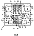
- Figure 8 shows a front view of the bottom part 60, and
- Figure 9 shows the design of phase, zero and earth contacts for the second embodiment.
- Bottom portion 60 is generally similar to that Constructed base part 12 of the first embodiment, although the input contacts and the contact frame are constructed and arranged differently, and as a result, they are longitudinal extending sets of input contact cover pillars the first embodiment by extending transversely Contact recesses 62 and respective support blocks 64 replaced.
- neutral conductor and earth is the Back of the bottom part 60 with two elongated Provide contact recesses 62, the end to end are arranged.
- the contact recesses for the phase the earth and neutral are side by side arranged to two sets of three parallel contact recesses 62 to form the back of the Bottom part 60, are positioned between the positions of sockets 10 on the front of the AC outlet.
- each contact recess 62 is one Carrier block 64 attached.
- the carrier block 64 is from the length shorter than the elongated recess and can from one end of the recess to the move others smoothly.
- Through the support block 64 two wire openings 65 are formed therethrough from the back of the bottom part to the on the Front of it attached input contacts extend.
- FIG. 10B shows the phase contact 70 for the second embodiment alone, without phase output contact parts 76.
- Phase contact 70 includes one elongated input contact part 72, one frame part 74 extends transversely from one end thereof. Like on best seen in Figure 9 is when viewing the front of the power outlet from the Phase input contact part 72 on the left side of the Base part structure, with the contact frame 74 in Is arranged towards the top of the structure and on each side up to the proximity of the respective Phase output contacts 76 for connection to the respective switches 8 (not shown in FIG. 9) extends.
- the input contact part 72 comprises two sets of input contacts (an upper and a lower one), each set of input contacts having two contact openings 75 and respective contact slots 73 comprises.
- Each contact opening 75 essentially comprises one circular hole, and each contact slot extends from one side of the circular hole and has essentially parallel edges.
- the Openings 75 and slots 73 are in each set alternately arranged, and the sentences are on opposite ends of the input contact part 72 arranged.
- the input contact part 72 is general flat, but angled with respect to the plane of the frame part 84.
- the frame part 84 and the input contact part 72 may be integrally formed, as previously with respect of the first embodiment, or it can be formed separately and by welding, Soldering, riveting or the like connected together be.
- FIG. 10C illustrates a zero contact 80 with an input contact part 82
- the construction the input contact part 72 of the phase contact 70 in general is similar.
- it extends the frame part 84 is from the center of the input contact part 82 and is at his of that Input contact part with distal ends in one piece Output contact parts 86 are formed.
- the frame parts 84 with respect to the input contact part slightly raised so that the frame part over can extend the phase and ground contact 70, 90 without electrical connection between when the zero contact 80 itself in place in the bottom part of the AC outlet is located as shown in Figure 9 shown.
- the zero input contact part 82 is at Viewing from the front as in Figure 8 and 9 shown on the right side of the bottom part structure arranged.
- the ground contact 90 shown in Figure 10A is also the structure of the zero and phase contact in generally similar, although its frame part 94 in Comparison to the phase contact 70 across from the opposite End of the input contact part 92 extends.
- the frame part 94 is at its from the input contact part distal ends in one piece with Output contact parts 96 are formed.
- the carrier blocks 64 can, as mentioned, within of the contact recesses 62 move smoothly.
- Carrier block 64 are the vein openings 65 with the Contact openings 75 of the respective set of input contacts aligned. If the carrier block 64 to the other end of the contact recess is moved the wire openings 65 with the corresponding Contact slots 73 of the respective set of input contacts aligned.
- the support blocks can be the end an insulated wire or cable from the back of the bottom part 60 into a vein aperture 65 are used, so that it by the appropriate Input contact opening 75 protrudes.
- the carrier block 64 then within the contact recess to its other If the end is moved, the end of the wire or of Cable that protrudes there into the angled contact slot 73 forced. Through this Operation is caused to cause edges of the slot 73 to Cut through the insulating jacket of the wire or cable and an electrical connection with the conductor in it produce.
- the movement of the support block 64 with there protruding core or cores can expediently using a screwdriver or the like with a leverage against one end of the Carrier blocks and one end of the recess 62 causes become.
- the support blocks 64 and the recesses 62 may be constructed so that between the recess end and the support block end one Lever opening 66 remains around a flat projection such as picking up a screwdriver tip.
- the corresponding support block 64 at this end of the Contact recess left can remove the wire or the cable End out on the support block a similar leverage be exercised to the core or the cable in the corresponding contact opening 75 for removing the End of the wire or cable to force.
- An input contact part according to a modification of the second embodiment is in a perspective in Figure 11 Shown view.
- the input contact part been formed separately from a frame part and is constructed so that it is welded at one end, Soldering, riveting or the like with a frame part can be connected.
- Those shown in Figure 11 Contact openings and respective contact slots are also shaped differently from those discussed above, where the contact openings are generally rectangular, with tapered parts in the respective contact slots to lead.
- the individual contact openings and slots on the input contact part shown in Figure 11 trained separately with regard to an improved structural rigidity of the contact part may be desirable, in particular then if it is made of a relatively thin sheet material or the like is made.
- the Contact slots, as shown in Figure 11 on bevels on opposite sides of the slit edges have to the when inserting the conductor Support insulation piercing and notches. All Slot and opening features can be in the same Direction can be arranged, or it can for example also a pair in the opposite of the other Direction.
Abstract
Description
Die vorliegende Erfindung betrifft Netzstromanschlußsteckdosen und Netzstromschalter.The present invention relates to power outlets and power switch.
In Wohn- und Geschäftsgebäuden werden häufig Netzstromanschlußsteckdosen verwendet, um Anschlüsse bereitzustellen, von denen aus elektrische Geräte mit Netzstrom versorgt werden können. In Australien beispielsweise kann eine Netzstromanschlußsteckdose in der Regel in einem unteren Bereich einer Wand installiert sein und Steckdosenbuchsen für drei Steckerstifte aufweisen, die einem Phasen-, einem Null- und einem Erdanschluß entsprechen. Innerhalb der Gebäudewand sind Verbindungsadern installiert, um die jeweiligen Kontakte der Steckdosenbuchsen beispielsweise beim elektrischen Schaltkasten oder Sicherungskasten des Gebäudes mit der Netzstromquelle und anderen Netzstromanschlußdosen im gleichen Bereich des Gebäudes zu verbinden. Um eine sichere elektrische Verbindung zwischen den Verbindungsadern in der Wand und den elektrischen Kontakten der Stromanschlußsteckdose herzustellen, sind traditionellerweise Schraubkontakte verwendet worden. Ein Schraubkontakt erfordert, daß von einem Ende der Verbindungsader die Isolierung entfernt wird und der freigelegte Leiter der Ader in eine Kontaktöffnung eingeführt wird und dann in sicheren elektrischen Kontakteingriff gelangt, indem eine Kontaktschraube in die Kontaktöffnung gedreht wird, um den freigelegten Teil des Leiters physisch und elektrisch in Eingriff zu nehmen. Dies ist zwar kein besonders schwieriger Vorgang, doch wenn viele Netzstromanschlußdosen installiert werden sollen, wäre es wünschenswert, die Anzahl und die Komplexität der Arbeitsgänge, die erforderlich sind, um mit jeder Netzstromanschlußdose elektrische Verbindungen herzustellen, zu reduzieren.In residential and commercial buildings are common Mains outlets used to make connections to provide from which electrical devices with Mains power can be supplied. In Australia for example, a power outlet in usually in a lower area of a wall be installed and socket outlets for three Have connector pins that have a phase, a zero and correspond to an earth connection. Within the Building walls are installed connecting wires to the respective contacts of the socket outlets for example with the electrical switch box or fuse box of the building with the mains power source and others Mains outlets in the same area of the building connect to. To ensure a safe electrical connection between the connecting wires in the wall and the electrical contacts of the power outlet are traditionally screw contacts been used. A screw contact requires that of the insulation is removed from one end of the connecting wire and the exposed conductor of the wire into one Contact opening is inserted and then in secure electrical contact engagement occurs by a Contact screw is turned into the contact opening the exposed part of the conductor physically and to engage electrically. While this is not particularly difficult process, but if many Mains outlets should be installed it desirable the number and complexity of Operations that are required to work with any power outlet make electrical connections, to reduce.
Gemäß der vorliegenden Erfindung ist eine Netzstromanschlußdose mit mindestens einer Netzstromanschlußsteckdose vorgesehen, die mehrere Steckdosenbuchsen mit entsprechenden elektrischen Anschlußkontakten zur Herstellung einer elektrischen Verbindung mit jeweiligen Stiften eines elektrischen Steckers bei Einsetzen in die Steckdosenbuchsen umfaßt und mehrere elektrische Eingangskontakte enthält, die an jeden elektrischen Anschlußkontakt elektrisch angekoppelt sind, um zwischen den elektrischen Anschlußkontakten und einer Netzstromquelle eine elektrische Verbindung herzustellen, wobei jeder elektrische Eingangskontakt ausgelegt ist, eine elektrische Verbindung mit einer Ader oder einem Kabel mit einem Isoliermantel herzustellen, wobei jeder elektrische Eingangskontakt mindestens eine Isolierschneidkante bzw. -fläche aufweist, die ausgelegt ist, bei einer Relativbewegung zwischen der Ader bzw. dem Kabel und dem elektrischen Eingangskontakt den Isoliermantel der besagten isolierten Ader bzw. des besagten Kabels zu durchschneiden und mit dem Leiter darin eine elektrische Verbindung herzustellen.According to the present invention is a power outlet with at least one mains socket provided the multiple socket outlets with appropriate electrical contacts to establish an electrical connection with respective pins of an electrical plug Inserting into the socket sockets includes and several contains electrical input contacts to each electrical connection contact electrically coupled are to between the electrical contacts and a mains power source an electrical connection establish, with each electrical input contact is designed to have an electrical connection with a To produce a wire or a cable with an insulating jacket, where each electrical input contact at least one insulating cutting edge or surface has, which is designed for a relative movement between the core or the cable and the electrical Input contact the insulating jacket of said insulated wire or said cable cut through and with the conductor in it establish electrical connection.
Die Grundlagen der vorliegenden Erfindung können gleichermaßen auch auf eine Netzstromschalteinheit übertragen werden, wie zum Beispiel solche, die zum Ein- und Ausschalten von Beleuchtungskörpern und dergleichen in Wohn- und Geschäftsgebäuden verwendet werden. In diesem Fall würden die elektrischen Eingangskontakte anstatt an einen elektrischen Anschlußkontakt, wie im Fall einer Netzstromanschlußdose, elektrisch an mindestens einen jeweiligen elektrischen Schaltkontakt angekoppelt werden.The basics of the present invention can also be used for a mains switch unit transmitted, such as those that for switching lighting fixtures on and off the like used in residential and commercial buildings become. In this case, the electrical input contacts instead of an electrical connector, like in the case of an AC outlet, electrically to at least one respective electrical Switching contact can be coupled.
Bei einer Umsetzung der Erfindung weist jede Netzstromanschlußsteckdose mindestens drei elektrische Anschlußkontakte auf, die einem Phasenanschluß, einem Nullanschluß und einem Erdanschluß entsprechen. Mit jedem dieser elektrischen Anschlußkontakte sind mehrere der elektrischen Eingangskontakte verbunden; bei den im folgenden Text dargestellten und beschriebenen Ausführungsformen liegen in jeder Netzstromanschlußdose vier elektrische Eingangskontakte vor, und jede Netzstromanschlußdose weist zwei Netzstromanschlußsteckdosen auf (d.h. zwei Sätze von elektrischen Anschlußkontakten und vier Sätze von elektrischen Eingangskontakten in jeder Netzstromanschlußdose, wobei jeder Satz von Kontakten eine Phase, einen Nulleiter und eine Erde umfaßt).In an implementation of the invention, each Mains socket at least three electrical Connection contacts on a phase connection, a Correspond to the zero connection and an earth connection. With each of these electrical connection contacts are several the electrical input contacts connected; at the in Embodiments shown and described in the following text there are four in each mains socket electrical input contacts in front, and each power outlet has two mains sockets (i.e. two sets of electrical contacts and four sets of electrical input contacts in each AC outlet, each set of contacts a phase, a neutral and an earth).
Gemäß einer Form der Erfindung umfaßt jeder der elektrischen Eingangskontakte ein Paar allgemein paralleler Kontaktbeine mit einem Schlitz zwischen jeweiligen gegenüberliegenden Kontaktkanten der Kontaktbeine. An den Enden der Kontaktbeine, wo die Beine sich geringfügig verjüngen, öffnet sich der Schlitz in einer allgemein V-förmigen Konfiguration nach außen, was das Einsetzen einer isolierten Ader oder eines isolierten Kabels in den Schlitz von dem offenen Ende aus erleichtert. Beim Einsetzen der isolierten Ader oder des isolierten Kabels quer zum Schlitz sind die Kontaktkanten ausgelegt, den Isoliermantel zu durchschneiden und mit dem Leiter der Ader oder des Kabels darin eine elektrische Verbindung herzustellen. Die Ader bzw. das Kabel wird in dem Schlitz zwischen den Kontaktkanten auch ganz sicher gehalten. Die über den Aderdurchmesser gebotene Ruhebreite des Schlitzes sollte offensichtlich so dimensioniert sein, daß sie mindestens kleiner ist als der Außendurchmesser des Isoliermantels, damit die Kontaktkanten die Isolierung durchschneiden können, obwohl dann, wenn die Kontaktbeine zur Verhinderung einer Verschiebung voneinander weg elastisch vorgespannt sind, der Schlitz so konstruiert sein kann, daß er verschiedene unterschiedliche Größen von isolierten Adern/Kabeln aufnimmt und mit ihnen eine Verbindung herstellt. Ein Ende der Ader bzw. des Kabels, die bzw. das mit der Netzstromanschlußsteckdose verbunden werden soll, zum Beispiel um sie mit Netzstrom zu versorgen, wird vorzugsweise unter Verwendung eines Einsetzwerkzeugs in den Schlitz eines elektrischen Eingangskontaktes eingesetzt.According to one form of the invention, each of the electrical input contacts a pair of generally parallel Contact legs with a slot between each opposite contact edges of the contact legs. At the ends of the contact legs where the legs are taper slightly, the slot opens in one generally V-shaped configuration to the outside what that Insert an insulated wire or an insulated one Cable into the slot from the open end facilitated. When inserting the insulated wire or of the insulated cable across the slot are Contact edges designed to cut through the insulating jacket and with the conductor of the wire or cable to make an electrical connection. The Wire or cable is in the slot between the Contact edges also held very securely. The about the Core diameter required idle width of the slot should obviously be dimensioned so that it is at least smaller than the outside diameter of the Insulation jacket, so that the contact edges the insulation can cut through, though, if the contact legs to prevent displacement from each other are elastically biased away, the slot like this can be constructed that he different different Insulated wire / cable sizes and connects with them. An end to the vein or the cable that or that with the AC outlet to be connected, for example to provide them with AC power is preferred using an insertion tool in the slot an electrical input contact.
Die Füße der Kontaktbeine sind vorzugsweise an einem Verbindungsrahmen angebracht, mit dem auch die anderen elektrischen Eingangskontakte und die elektrischen Anschlußkontakte verbunden sind. Bei der bevorzugten Ausführungsform sind der Rahmen, die elektrischen Eingangskontakte und die elektrischen Anschlußkontakte alle einstückig aus einem einzelnen Stück eines entsprechenden leitenden Metallmaterials geformt. Dieses kann beispielsweise durch Stanzen aus Blech und Biegen oder Drücken der gestanzten Kontakte und des gestanzten Rahmens in die erforderliche Form geformt werden. Im Fall der Phasenkontakte ist bevorzugt, daß die elektrischen Anschlußkontakte aus von den elektrischen Eingangskontakten und dem Rahmen unterschiedlichen Stücken von Material hergestellt werden, so daß ein Schaltmechanismus verwendet werden kann, um eine elektrische Verbindung gezielt zwischen den elektrischen Eingangskontakten und den jeweiligen elektrischen Anschlußkontakten herzustellen.The feet of the contact legs are preferably on attached a connecting frame with which the other electrical input contacts and the electrical Connection contacts are connected. In the preferred embodiment are the frame, the electrical Input contacts and the electrical Connection contacts all in one piece from a single Piece of a corresponding conductive metal material shaped. This can be done, for example, by punching Sheet metal and bending or pressing the stamped contacts and the punched frame into the required shape be shaped. In the case of phase contacts preferred that the electrical connection contacts from from the electrical input contacts and the frame different pieces of material be used so that a switching mechanism can to selectively establish an electrical connection between the electrical input contacts and the respective produce electrical connection contacts.
Gemäß einer weiteren Form der Erfindung umfaßt jeder der elektrischen Eingangskontakte einen allgemein flachen Kontaktteil mit einem darin ausgebildeten Schlitz, wobei der Schlitz einen engen Halteteil mit allgemein parallelen Kontaktkanten neben einem verbreiterten Einsteckteil aufweist. Die Kontaktkanten des Halteteils sind so beabstandet, daß die Isolierung einer darin eingesetzten Ader bzw. eines derartigen Kabels von den Kanten geschnitten wird, so daß die Kanten mit dem Leiter der Ader bzw. des Kabels eine elektrische Verbindung herstellen. Der Einsteckteil ist so dimensioniert, daß ein Ende der Ader bzw. des Kabels darin quer zur Ebene des flachen Kontaktteils zur späteren Bewegung parallel zum Schlitz in den Halteteil eingesteckt werden kann. In dieser Form der Erfindung ist bevorzugt, daß ein gleitendes Element vorgesehen ist und von der Netzstromanschlußsteckdose neben einer flachen Seite des flachen Kontaktteils des elektrischen Eingangskontakts getragen wird. Durch das gleitende Element geht eine Öffnung, und es läßt sich verschieben, so daß die Öffnung von einer Ausrichtung mit dem Einsteckteil zu einer Ausrichtung mit dem Halteteil bewegt werden kann. Bei Gebrauch wird das isolierte Ende der Ader bzw. des Kabels, mit der bzw. mit dem ein Kontakt hergestellt werden soll, durch die Öffnung in dem gleitenden Element und in den Einsteckteil des Schlitzes gesteckt. Das gleitende Element wird dann in Ausrichtung mit dem Halteteil des Schlitzes bewegt, was wiederum die Ader bzw. das Kabel zwischen die Kontaktkanten des Halteteils zwingt, wodurch die Isolierung durchschnitten wird und zwischen den Kanten und dem Leiter der Ader bzw. des Kabels eine elektrische Verbindung hergestellt wird.According to a further form of the invention comprises each of the electrical input contacts a general flat contact part with a trained therein Slot, the slot having a narrow holding part generally parallel contact edges next to a widened Has insert part. The contact edges of the Holding part are spaced so that the insulation a wire used therein or such Cable is cut from the edges so that the Edge with the conductor of the core or the cable one Establish electrical connection. The plug-in part is dimensioned so that one end of the wire or cable therein transverse to the plane of the flat contact part later movement parallel to the slot in the holding part can be inserted. In this form of the invention it is preferred that a sliding member is provided is and from the power outlet next to one flat side of the flat contact part of the electrical Input contact is worn. Through the sliding Element goes through an opening and it can be moved so that the opening is in alignment with the Insert part for alignment with the holding part can be moved. When used, the isolated End of the wire or cable, with the one Contact should be made through the opening in the sliding element and in the insertion part of the Slot inserted. The sliding element is then in Alignment with the holding part of the slot moves what again the wire or the cable between the contact edges of the holding part forces, causing the insulation is intersected and between the edges and the Conductor of the wire or cable an electrical Connection is established.
Die Erfindung stellt auch eine Netzstromschalteinheit bereit, die zur Verwendung beim Schalten von Netzstrom zu Beleuchtungskörpern und dergleichen ausgelegt ist, mit mindestens einem elektrischen Eingangskontakt, mindestens einem entsprechenden elektrischen Anschlußkontakt und einem zwischen dem mindestens einen elektrischen Eingangskontakt und Anschlußkontakt gekoppelten Schaltmittel zum elektrischen Verbinden und Trennen der entsprechenden Eingangs- und Anschlußkontakte zur Steuerung der Zufuhr von Netzstrom zwischen an den mindestens einen elektrischen Eingangs- und Anschlußkontakt angekoppelten Stromkreisen, wobei jeder der elektrischen Eingangs- und Anschlußkontakte ausgelegt ist, eine elektrische Verbindung mit einer Ader oder einem Kabel mit einem Isoliermantel herzustellen, und wobei jeder elektrische Kontakt mindestens eine Isolierschneidkante bzw. -fläche aufweist, die ausgelegt ist, bei einer Relativbewegung zwischen der Ader bzw. dem Kabel und dem elektrischen Kontakt den Isoliermantel der besagten isolierten Ader bzw. des besagten Kabels zu durchschneiden und mit dem Leiter darin eine elektrische Verbindung herzustellen.The invention also provides an AC power switch unit ready for use when switching from Mains power designed for lighting fixtures and the like with at least one electrical input contact, at least one corresponding electrical Connection contact and one between the at least one coupled electrical input contact and connection contact Switching means for electrical connection and Separate the corresponding input and Connection contacts for controlling the supply of mains power between at least one electrical input and Connection contact coupled circuits, wherein each of the electrical input and connection contacts is designed to have an electrical connection with a To produce a wire or a cable with an insulating jacket, and with each electrical contact at least has an insulating cutting edge or surface that is designed for a relative movement between the Core or the cable and the electrical contact Insulating jacket of said insulated wire or to cut said cable and with the conductor to make an electrical connection.
Die Erfindung wird im folgenden Text anhand von
Ausführungsformen, die in den beiliegenden Zeichnungen
dargestellt sind, lediglich beispielhaft näher
beschrieben. Es zeigen:
Eine Vorderansicht einer Netzstromanschlußdose
2 ist in Figur 1 dargestellt, die in diesem Fall
ausgelegt ist, mit zwei standardmäßigen Haushaltsstromsteckern
mit drei Stiften eine getrennte elektrische
Verbindung herzustellen. Eine Abdeckplatte 6 und eine
Bodenteilabdeckung 4 decken die Netzstromanschlußdose
von der Vorderseite aus ab. Für jede Steckdose 10 weist
die Bodenteilabdeckung drei Stiftöffnungen und einen
entsprechenden Schalter 8 auf, der durch die Bodenteilabdeckung
ragt. A front view of a
Figur 2 veranschaulicht einen Bodenteil 12
einer Netzstromanschlußdose gemäß einer ersten
Ausführungsform der vorliegenden Erfindung von hinten
aus gesehen, und Figur 3 ist eine Vorderansicht des
Bodenteils 12 mit entfernter Bodenteilabdeckung. Wie
aus Figur 3 ersichtlich, sind am Bodenteil 12 zwei
Sätze von Phasen-, Null- bzw. Erdausgangskontakten 34,
44 bzw. 54 angeordnet und sitzen in jeweiligen
Ausnehmungen des Bodenteils. Wenn die Bodenteilabdeckung
4 über dem Bodenteil 12 angebracht ist, sind
die Öffnungen für die Steckdosen 10 mit jeweiligen
Ausgangskontakten ausgerichtet, damit durch die Öffnungen
einzusteckende Steckerstifte in den Ausgangskontakten
in Eingriff genommen werden können.Figure 2 illustrates a bottom part 12
a mains socket according to a first
Embodiment of the present invention from behind
seen from, and Figure 3 is a front view of the
Drei Sätze von Eingangskontakten sind vorgesehen,
die Phaseneingangskontakte 32, Nulleingangskontakte
42 und Erdeingangskontakte 52 umfassen. Jeder
Satz umfaßt vier Eingangskontakte, die durch jeweilige
Kontaktrahmen 30, 40, 50 (entsprechend Phase, Nulleiter
und Erde) miteinander verbunden werden. Im Fall des
Nulleiters und der Erde sind die Kontaktrahmen 40, 50
auch direkt mit den jeweiligen Null- und Erdausgangskontakten
44, 54 verbunden. Im Fall des Phasenkontaktrahmens
30 jedoch sind die Phasenausgangskontakte 34
getrennt ausgebildet, so daß die Schalter 8 die
elektrische Verbindung zwischen den jeweiligen
Phasenausgangskontakten 34 und den Phasenkontaktrahmen- und
-eingangskontakten steuern können. Figur 4 veranschaulicht
die Gestaltung der Kontakte und Kontaktrahmen
getrennt vom Bodenteil 12.Three sets of input contacts are provided
the
Von vorne gesehen wird jeder der Eingangskontakte
in einer getrennten Ausnehmung in dem
Bodenteil 12 aufgenommen, wobei die je vier Ausnehmungen
für die Phase, den Nulleiter bzw. Erde in
jeweiligen horizontalen Reihen angeordnet sind. Die
horizontalen Reihen entsprechen den drei Reihen von
Eingangskontaktabdeckungssäulen 20, 21, 22
(entsprechend Phase, Nulleiter und Erde), die von der
Rückseite des Bodenteils 12 aus vorstehen. Die
Ausnehmungen in der Vorderseite des Bodenteils entsprechen
jeweils einer jeweiligen Aderkontaktöffnung 24
in den Säulen 20, 21, 22. Dementsprechend wird jeder
Eingangskontakt in einer jeweiligen Aderkontaktöffnung
24 aufgenommen, innerhalb der der Zugang zu den
Eingangskontakten offen ist, um sie mit einer isolierten
Ader oder einem isolierten Kabel zu kontaktieren.
Die Ausgangskontakte 34, 44, 54 werden von der
Rückseite aus durch Anschlußkontaktabdeckungen 18
geschützt (Figur 2).Each of the input contacts is seen from the front
in a separate recess in the
Die Figur 5A zeigt zwei Ansichten der
einstückig ausgebildeten Erdeingangskontakte, des
Kontaktrahmens bzw. der Ausgangskontakte 52, 50, 54.
Die Eingangs- und Ausgangskontakte und der Kontaktrahmen
sind einstückig aus einem Stück aus
Blechmaterial oder dergleichen durch Stanzen einer
erforderlichen Form und nachfolgendes Biegen oder
sonstiges Formen des gestanzten Blechmaterials in die
gewünschte Konfiguration, wie sie in der Figur
dargestellt ist, geformt. Der Kontaktrahmen 50 ist
länglich, wobei die Ausgangskontakte 54 an jedem Ende
positioniert sind, und die Eingangskontakte 52 sind
dort entlang zwischen den beiden Ausgangskontakten
beabstandet. Die Ausgangskontakte weisen eine im
allgemeinen herkömmliche Form zur Aufnahme flacher
Kontaktstifte eines Haushaltssteckers oder dergleichen
auf und sind im allgemeinen u-förmig und nach oben
offen, wie in der Figur gezeigt. Die Eingangskontakte
52 sind von dem Kontaktrahmen aus nach unten gebogen,
und die Ebene jedes Eingangskontaktes ist so gebogen,
daß sie sich quer zur Erstreckung des Kontaktrahmens
erstreckt, vorzugsweise etwa mit 45° dazu. Jeder
Eingangskontakt 52 umfaßt zwei parallele Beine mit
einem Schlitz dazwischen, der sich nach unten öffnet,
wobei die Öffnung in einer allgemein v-förmigen
Konfiguration an den Enden der Kontaktbeine ausgebildet
ist, um das Einsetzen einer Ader oder eines Kabels
zwischen den Kontaktbeinen zu erleichtern. Entlang des
Schlitzes weisen die Kontaktbeine jeweilige Kontaktkanten
auf, die parallel verlaufen und eng genug
beabstandet sind, damit bei Einsetzen einer isolierten
Ader dazwischen von der Schlitzöffnung aus die
Kontaktkanten Teile des Isoliermantels durchschneiden
und eine elektrische Verbindung mit dem Leiter darin
herstellen und die Ader auch mechanisch in Eingriff
nehmen. Der Schlitz kann sich am Fuß der Beine
verbreitern, um den Beinen eine geringfügig größere
elastische Nachgiebigkeit zum Unterbringen der Ader
zwischen den Kontaktkanten zu geben.FIG. 5A shows two views of the
one-piece earth input contacts, the
Contact frame or the
Figur 5C veranschaulicht zwei Ansichten der
Nulleingangs- und -ausgangskontakte und des Kontaktrahmens,
der vom Aufbau her der im Zusammenhang mit
Figur 5A beschriebenen Anordnung ähnlich ist, obwohl
die Ausgangskontakte 44 unter Winkeln angeordnet sind,
um der Orientierung der darin aufzunehmenden jeweiligen
Steckerstifte zu entsprechen.Figure 5C illustrates two views of the
Zero input and output contacts and the contact frame,
the structurally related to
Figure 5A is similar to the arrangement described, though
the
Figur 5B veranschaulicht die Phaseneingangskontakte
und den Kontaktrahmen 32, 30, der vom Aufbau
her ebenfalls den Erdeingangskontakten und dem Kontaktrahmen
52, 50 ähnlich ist. Im Fall der Phase jedoch
sind, wie oben erörtert, die Ausgangskontakte getrennt
ausgebildet und neben den Enden des Kontaktrahmens 30
angeordnet, wie in Figur 4 dargestellt.Figure 5B illustrates the phase input contacts
and the
Bei einer Form dieser Ausführungsform der Erfindung können die Eingangskontakte so ausgebildet sein, daß sie jeweils zu Adern bzw. Kabeln unterschiedlicher Größen passen. So könnten beispielsweise zwei der Eingangskontakte von jeweils Phase, Nulleiter und Erde mit einem relativ schmalen Spalt zwischen den Kontaktkanten und die beiden anderen Eingangskontakte mit einem relativ breiten Spalt zwischen jeweiligen Kontaktkanten versehen sein, um zu unterschiedlichen Größen von Kabel- oder Aderleitern zu passen. Alternativ kann die Elastizität der Beine der Eingangskontakte derart sein, daß zum Aufnehmen unterschiedlicher Größen von Ader oder Kabel in einem gegebenen Eingangskontakt keine Schlitze unterschiedlicher Größe erforderlich sind. In one form of this embodiment the According to the invention, the input contacts can be designed in this way be different from each other to wires or cables Sizes fit. For example, two the input contacts of each phase, neutral and Earth with a relatively narrow gap between the Contact edges and the two other input contacts with a relatively wide gap between each Contact edges to be provided to different To fit sizes of cable or wire conductors. Alternatively, the elasticity of the legs of the Input contacts should be such that different ones can be used Wire or cable sizes in one given input contact no slots of different Size are required.
Wie am besten in Figur 2 zu sehen, sind die
Schlitze zwischen Beinen der Eingangskontakte für die
Phase, den Nulleiter und die Erde in der Aderkontaktöffnung
24 der jeweiligen Reihen von Eingangskontaktabdeckungssäulen
20, 21 und 22 zugänglich. Die
Aderkontaktöffnungen und somit die Eingangskontakte
sind selbst bei angebrachter Bodenteilabdeckung 4 und
angebrachter Abdeckplatte 6 von der Rückseite der
Netzstromanschlußdose 2 aus zugänglich, ragen aber
normalerweise in die Wand oder dergleichen hinein, wenn
die Netzstromanschlußdose zum Betrieb montiert ist.As best seen in Figure 2, these are
Slots between legs of the input contacts for the
Phase, the neutral conductor and the earth in the
Unter Bezugnahme auf Figur 2 liegen die
Aderkontaktöffnungen 24 in der Form von Spalten in den
Eingangskontaktabdeckungssäulen (20, 21, 22) vor, und
die einzelnen Eingangskontakte (32, 42, 52) sind in
jeweiligen individuellen Aderkontaktöffnungen 24 quer
angeordnet (vorzugsweise unter etwa 45°). Auf diese
Weise kann eine Ader oder ein Kabel von der Rückseite
des Bodenteils 12 aus zur Ineingriffnahme des
entsprechenden Eingangskontaktes in eine bestimmte
Aderkontaktöffnung 24 eingesetzt werden. Das Ader- bzw.
Kabelende wird mit seiner Länge im allgemeinen parallel
zu der Ebene des Bodenteils und im rechten Winkel zur
Erstreckung der Kontaktabdeckungssäule oder des
Eingangskontaktrahmens eingesetzt. Da die Eingangskontakte
bezüglich einer in die entsprechende Kontaktöffnung
eingesetzten Ader abgewinkelt sind, sind die
Kanten des Eingangskontaktschlitzes möglicherweise beim
Durchschneiden der Aderisolierung zur Herstellung einer
elektrischen Verbindung mit dem Leiter darin wirksamer.
Um eine Verbindung mit den Eingangskontakten herzustellen,
können Adern zweckmäßigerweise in die Aderkontaktöffnungen
mit Hilfe eines Werkzeugs eingesetzt
werden, das als "Terminator"-Werkzeug (Warenzeichen)
bekannt ist und von der Firma Krone (Australia)
Technique Pty Limited erhältlich ist.With reference to Figure 2, the
Figur 7 veranschaulicht die Rückseite eines
gemäß einer zweiten Ausführungsform der vorliegenden
Erfindung konstruierten Bodenteils 60. Figur 8 zeigt
eine Vorderansicht des Bodenteils 60, und Figur 9 zeigt
die Gestaltung von Phasen-, Null- und Erdkontakten für
die zweite Ausführungsform.Figure 7 illustrates the back of a
according to a second embodiment of the present
Invention constructed
Der Bodenteil 60 ist allgemein ähnlich dem
Bodenteil 12 der ersten Ausführungsform konstruiert,
obwohl die Eingangskontakte und die Kontaktrahmen
unterschiedlich konstruiert und angeordnet sind, und
infolgedessen sind die sich in Längsrichtung
erstreckenden Sätze von Eingangskontaktabdeckungssäulen
der ersten Ausführungsform durch sich quer erstreckende
Kontaktausnehmungen 62 und jeweilige Trägerblöcke 64
ersetzt. Für jeweils Phase, Nulleiter und Erde ist die
Rückseite des Bodenteils 60 mit zwei länglichen
Kontaktausnehmungen 62 versehen, die Ende an Ende
angeordnet sind. Die Kontaktausnehmungen für die Phase,
die Erde und den Nulleiter sind Seite an Seite
angeordnet, um zwei Sätze von drei parallelen Kontaktausnehmungen
62 zu bilden, die auf der Rückseite des
Bodenteils 60, positioniert sind zwischen den Positionen
der Steckdosen 10 auf der Vorderseite der
Netzstromanschlußdose.
Innerhalb jeder Kontaktausnehmung 62 ist ein
Trägerblock 64 angebracht. Der Trägerblock 64 ist von
der Länge her kürzer als die längliche Ausnehmung und
läßt sich von einem Ende der Ausnehmung aus zu dem
anderen gleitend bewegen. Durch den Trägerblock 64
hindurch sind zwei Aderöffnungen 65 ausgebildet, die
sich von der Rückseite des Bodenteils aus zu den an der
Vorderseite davon angebrachten Eingangskontakten
erstrecken.Within each
Figur 10B zeigt den Phasenkontakt 70 für die
zweite Ausführungform alleine, ohne Phasenausgangskontaktteile
76. Der Phasenkontakt 70 umfaßt einen
länglichen Eingangskontaktteil 72, wobei ein Rahmenteil
74 sich von einem Ende davon aus quer erstreckt. Wie am
besten in Figur 9 zu sehen, liegt bei Betrachtung von
der Vorderseite der Netzstromanschlußdose aus der
Phaseneingangskontaktteil 72 auf der linken Seite der
Bodenteilstruktur, wobei der Kontaktrahmen 74 in
Richtung der Oberseite der Struktur angeordnet ist und
sich nach jeder Seite bis in die Nähe der jeweiligen
Phasenausgangskontakte 76 zur Verbindung mit den
jeweiligen Schaltern 8 (in Figur 9 nicht gezeigt)
erstreckt. Der Eingangskontaktteil 72 umfaßt zwei Sätze
von Eingangskontakten (einen oberen und einen unteren),
wobei jeder Satz von Eingangskontakten zwei Kontaktöffnungen
75 und jeweilige Kontaktschlitze 73 umfaßt.
Jede Kontaktöffnung 75 umfaßt ein im wesentlichen
kreisförmiges Loch, und jeder Kontaktschlitz erstreckt
sich von einer Seite des kreisförmigen Loches aus und
weist im wesentlichen parallele Kanten auf. Die
Öffnungen 75 und die Schlitze 73 sind in jedem Satz
abwechselnd angeordnet, und die Sätze sind an
entgegengesetzten Enden des Eingangskontaktteils 72
angeordnet. Der Eingangskontaktteil 72 ist allgemein
eben, aber bezüglich der Ebene des Rahmenteils 84 abgewinkelt.
Der Rahmenteil 84 und der Eingangskontaktteil
72 können einstückig ausgebildet sein, wie zuvor bezüglich
der ersten Ausführungsform erörtert, oder sie
können getrennt ausgebildet sein und durch Schweißen,
Löten, Nieten oder dergleichen miteinander verbunden
sein.FIG. 10B shows the
Figur 10C veranschaulicht einen Nullkontakt 80
mit einem Eingangskontaktteil 82, der vom Aufbau her
dem Eingangskontaktteil 72 des Phasenkontaktes 70 allgemein
ähnlich ist. In diesem Fall allerdings erstreckt
sich der Rahmenteil 84 von der Mitte des Eingangskontaktteils
82 aus und ist an seinen von dem
Eingangskontaktteil entfernten Enden einstückig mit
Ausgangskontaktteilen 86 ausgebildet. Weiterhin sind
die Rahmenteile 84 bezüglich des Eingangskontaktteils
geringfügig angehoben, damit der Rahmenteil sich über
den Phasen- und Erdkontakt 70, 90 erstrecken kann, ohne
elektrische Verbindung dazwischen, wenn der Nullkontakt
80 sich an Ort und Stelle in dem Bodenteil der
Netzstromanschlußdose befindet, wie in Figur 9 angeordnet
gezeigt. Der Nulleingangskontaktteil 82 ist bei
Betrachtung von der Vorderseite aus, wie in Figuren 8
und 9 gezeigt, auf der rechten Seite der Bodenteilstruktur
angeordnet.FIG. 10C illustrates a zero
Der in Figur 10A dargestellte Erdkontakt 90 ist
ebenfalls vom Aufbau her dem Null- und Phasenkontakt im
allgemeinen ähnlich, obwohl sich sein Rahmenteil 94 im
Vergleich zu dem Phasenkontakt 70 quer vom entgegengesetzten
Ende des Eingangskontaktteils 92 aus erstreckt.
Der Rahmenteil 94 ist an seinen von dem Eingangskontaktteil
entfernten Enden einstückig mit
Ausgangskontaktteilen 96 ausgebildet.The
Nunmehr unter besonderer Bezugnahme auf Figur 7
lassen sich die Trägerblöcke 64, wie erwähnt, innerhalb
der Kontaktausnehmungen 62 gleitend bewegen. Bei an
einem Ende der jeweiligen Kontaktausnehmung 62 angeordnetem
Trägerblock 64 sind die Aderaperturen 65 mit den
Kontaktöffnungen 75 des jeweiligen Satzes von Eingangskontakten
ausgerichtet. Wenn der Trägerblock 64 zu dem
anderen Ende der Kontaktausnehmung bewegt wird, sind
die Aderöffnungen 65 mit den entsprechenden
Kontaktschlitzen 73 des jeweiligen Satzes von Eingangskontakten
ausgerichtet. Bei in der zuerst erwähnten
Konfiguration befindlichen Trägerblöcken kann das Ende
einer isolierten Ader oder eines isolierten Kabels von
der Rückseite des Bodenteils 60 aus in eine Aderapertur
65 eingesetzt werden, so daß es durch die entsprechende
Eingangskontaktöffnung 75 ragt. Wenn der Trägerblock 64
dann innerhalb der Kontaktausnehmung zu dessen anderem
Ende bewegt wird, wird das Ende der Ader oder des
Kabels, die bzw. das dort hineinragt, in den
abgewinkelten Kontaktschlitz 73 gezwungen. Durch diesen
Vorgang wird bewirkt, daß Kanten des Schlitzes 73 den
Isoliermantel der Ader oder des Kabels durchschneiden
und mit dem Leiter darin eine elektrische Verbindung
herstellen. Die Bewegung des Trägerblocks 64 mit dort
hineinragender Ader oder Adern kann zweckmäßigerweise
unter Verwendung eines Schraubendrehers oder
dergleichen mit einer Hebelwirkung gegen ein Ende des
Trägerblocks und ein Ende der Ausnehmung 62 bewirkt
werden. Zu diesem Zweck können die Trägerblöcke 64 und
die Ausnehmungen 62 so konstruiert sein, daß zwischen
dem Ausnehmungsende und dem Trägerblockende eine
Hebelöffnung 66 verbleibt, um einen flachen Vorsprung
wie beispielsweise eine Schraubendreherspitze aufzunehmen.
Nachdem mit einer Ader oder einem Kabel eine
elektrische Verbindung hergestellt worden ist, wird der
entsprechende Trägerblock 64 an diesem Ende der
Kontaktausnehmung gelassen. Wenn erwünscht ist, die
Ader bzw. das Kabel zu entfernen, kann von dem anderen
Ende aus auf den Trägerblock eine ähnliche Hebelwirkung
ausgeübt werden, um die Ader bzw. das Kabel in die
entsprechende Kontaktöffnung 75 zum Herausnehmen des
Endes der Ader bzw. des Kabels zu zwingen.Now with particular reference to Figure 7
the carrier blocks 64 can, as mentioned, within
of the contact recesses 62 move smoothly. At at
one end of the
Es versteht sich, daß es nicht unerläßlich ist, daß die Eingangskontaktöffnungen und -schlitze so geformt sind, wie in Figuren 7 bis 10 dargestellt, und es sind viele Abwandlungen möglich. Ein Eingangskontaktteil gemäß einer Abwandlung der zweiten Ausführungsform ist in Figur 11 in einer perspektivischen Ansicht dargestellt. Hier ist der Eingangskontaktteil von einem Rahmenteil getrennt ausgebildet worden und ist so aufgebaut, daß er an einem Ende durch Schweißen, Löten, Nieten oder dergleichen mit einem Rahmenteil verbunden werden kann. Die in Figur 11 gezeigten Kontaktöffnungen und jeweiligen Kontaktschlitze sind ebenfalls anders geformt als die oben erörterten, wobei die Kontaktöffnungen in der Regel rechteckig sind, wobei verjüngte Teile in die jeweiligen Kontaktschlitze führen. Auch sind die einzelnen Kontaktöffnungen und -schlitze an dem in Figur 11 dargestellten Eingangskontaktteil getrennt ausgebildet, was im Hinblick auf eine verbesserte strukturelle Starrheit des Kontaktteils möglicherweise wünschenswert ist, insbesondere dann, wenn er aus einem relativ dünnen Blattmaterial oder dergleichen hergestellt ist. Weiterhin können die Kontaktschlitze, wie sie in Figur 11 gezeigt sind, auf gegenüberliegenden Seiten der Schlitzkanten Abfasungen aufweisen, um beim Einsetzen des Aderleiters das Schneidklemmen und Kerben zu unterstützen. Alle Schlitz- und Öffnungsmerkmale können in der gleichen Richtung angeordnet sein, oder es kann beispielsweise auch ein Paar in der dem anderen entgegengesetzten Richtung angeordnet sein.It goes without saying that it is not essential that the input contact openings and slots so are shaped as shown in Figures 7 to 10, and many modifications are possible. An input contact part according to a modification of the second embodiment is in a perspective in Figure 11 Shown view. Here is the input contact part been formed separately from a frame part and is constructed so that it is welded at one end, Soldering, riveting or the like with a frame part can be connected. Those shown in Figure 11 Contact openings and respective contact slots are also shaped differently from those discussed above, where the contact openings are generally rectangular, with tapered parts in the respective contact slots to lead. The individual contact openings and slots on the input contact part shown in Figure 11 trained separately with regard to an improved structural rigidity of the contact part may be desirable, in particular then if it is made of a relatively thin sheet material or the like is made. Furthermore, the Contact slots, as shown in Figure 11 on bevels on opposite sides of the slit edges have to the when inserting the conductor Support insulation piercing and notches. All Slot and opening features can be in the same Direction can be arranged, or it can for example also a pair in the opposite of the other Direction.
Aus der obigen Beschreibung geht für den Durchschnittsfachmann ohne weiteres hervor, daß die hier offenbarten Netzstromanschlußdosen und insbesondere die Konstruktion und Anordnung der Eingangskontakte eine einfache und schnelle Verbindung mit elektrischen Adern bzw. Kabeln erlauben, was unter Verwendung herkömmlicher Verbinder nicht möglich war. Es ist nicht erforderlich, vor der Herstellung der Verbindung die Isolierung von der Ader bzw. dem Kabel zu entfernen, und der Vorgang des Verbindens ist besonders einfach und erfordert nur ein einfaches Werkzeug.The above description is for the average specialist without further ado that this one disclosed power outlets and in particular the Construction and arrangement of the input contacts simple and quick connection with electrical wires or cables allow what using conventional Connector was not possible. It is not required before making the connection Remove insulation from the wire or cable, and the process of connecting is particularly simple and just requires a simple tool.
Die obige ausführliche Beschreibung der vorliegenden Erfindung ist lediglich beispielhaft vorgetragen worden und soll nicht als eine Begrenzung der vorliegenden Erfindung angesehen werden, wie sie in den hier beigefügten Ansprüchen definiert ist.The above detailed description of the present The invention is presented by way of example only has been and is not intended to limit the Present invention can be viewed as in the claims appended hereto.
Claims (23)
Applications Claiming Priority (2)
| Application Number | Priority Date | Filing Date | Title |
|---|---|---|---|
| AUPP068097 | 1997-12-02 | ||
| AUPP0680A AUPP068097A0 (en) | 1997-12-02 | 1997-12-02 | Electrical power outlet |
Publications (3)
| Publication Number | Publication Date |
|---|---|
| EP0921611A2 true EP0921611A2 (en) | 1999-06-09 |
| EP0921611A3 EP0921611A3 (en) | 2001-03-14 |
| EP0921611B1 EP0921611B1 (en) | 2003-06-04 |
Family
ID=3804964
Family Applications (1)
| Application Number | Title | Priority Date | Filing Date |
|---|---|---|---|
| EP98121647A Expired - Lifetime EP0921611B1 (en) | 1997-12-02 | 1998-11-12 | Mains socket and -switch |
Country Status (11)
| Country | Link |
|---|---|
| US (1) | US6095848A (en) |
| EP (1) | EP0921611B1 (en) |
| JP (1) | JPH11250947A (en) |
| CN (1) | CN1219005A (en) |
| AT (1) | ATE242558T1 (en) |
| AU (1) | AUPP068097A0 (en) |
| DE (1) | DE59808612D1 (en) |
| DK (1) | DK0921611T3 (en) |
| ES (1) | ES2197413T3 (en) |
| NZ (1) | NZ332913A (en) |
| PT (1) | PT921611E (en) |
Families Citing this family (6)
| Publication number | Priority date | Publication date | Assignee | Title |
|---|---|---|---|---|
| US8246361B2 (en) * | 2006-05-09 | 2012-08-21 | Adc Gmbh | Electrical connector |
| AU2008247297B2 (en) * | 2007-05-04 | 2011-10-06 | Commscope Technologies Llc | Power outlet |
| US9246321B2 (en) * | 2014-03-25 | 2016-01-26 | Roger Fulton NEWILL | Wiring apparatus |
| US9948013B2 (en) * | 2015-09-03 | 2018-04-17 | Steven D Houseworth | Modular electrical power transfer device for integrated power platform |
| CN107534245B (en) * | 2015-09-14 | 2019-12-24 | 京瓷株式会社 | Branch connector |
| CN112398066B (en) * | 2019-08-13 | 2023-02-07 | 帕西·西姆公司 | Electrical wiring device with flexible terminal for eliminating ground connection |
Citations (4)
| Publication number | Priority date | Publication date | Assignee | Title |
|---|---|---|---|---|
| US4223971A (en) * | 1979-01-05 | 1980-09-23 | Amp Incorporated | Electrical wiring assembly and method |
| US4463998A (en) * | 1982-03-04 | 1984-08-07 | Amp Incorporated | Connector assembly for undercarpet cable |
| GB2256323A (en) * | 1991-05-31 | 1992-12-02 | Ever Winner Electric Works Ltd | Electrical trailing socket with switches |
| DE9313797U1 (en) * | 1993-09-07 | 1995-03-23 | Krone Ag | Terminal block |
Family Cites Families (5)
| Publication number | Priority date | Publication date | Assignee | Title |
|---|---|---|---|---|
| US3860319A (en) * | 1973-09-13 | 1975-01-14 | Thomas S Slater | Boxless electrical component |
| US3868161A (en) * | 1973-10-01 | 1975-02-25 | Amp Inc | Electrical component |
| US4775332A (en) * | 1985-01-24 | 1988-10-04 | Slater Electric, Inc. | Electrical receptacle |
| US5088934A (en) * | 1991-02-20 | 1992-02-18 | Chian Chyun Enterprise Co. Ltd. | Electrical terminal |
| DE4403278C2 (en) * | 1994-01-31 | 1997-12-04 | Krone Ag | IDC contact element |
-
1997
- 1997-12-02 AU AUPP0680A patent/AUPP068097A0/en not_active Abandoned
-
1998
- 1998-11-12 AT AT98121647T patent/ATE242558T1/en not_active IP Right Cessation
- 1998-11-12 EP EP98121647A patent/EP0921611B1/en not_active Expired - Lifetime
- 1998-11-12 PT PT98121647T patent/PT921611E/en unknown
- 1998-11-12 DK DK98121647T patent/DK0921611T3/en active
- 1998-11-12 ES ES98121647T patent/ES2197413T3/en not_active Expired - Lifetime
- 1998-11-12 DE DE59808612T patent/DE59808612D1/en not_active Expired - Fee Related
- 1998-11-19 NZ NZ332913A patent/NZ332913A/en unknown
- 1998-11-25 US US09/200,217 patent/US6095848A/en not_active Expired - Lifetime
- 1998-12-02 CN CN98122382A patent/CN1219005A/en active Pending
- 1998-12-02 JP JP10343051A patent/JPH11250947A/en active Pending
Patent Citations (4)
| Publication number | Priority date | Publication date | Assignee | Title |
|---|---|---|---|---|
| US4223971A (en) * | 1979-01-05 | 1980-09-23 | Amp Incorporated | Electrical wiring assembly and method |
| US4463998A (en) * | 1982-03-04 | 1984-08-07 | Amp Incorporated | Connector assembly for undercarpet cable |
| GB2256323A (en) * | 1991-05-31 | 1992-12-02 | Ever Winner Electric Works Ltd | Electrical trailing socket with switches |
| DE9313797U1 (en) * | 1993-09-07 | 1995-03-23 | Krone Ag | Terminal block |
Also Published As
| Publication number | Publication date |
|---|---|
| NZ332913A (en) | 2001-04-27 |
| ATE242558T1 (en) | 2003-06-15 |
| DE59808612D1 (en) | 2003-07-10 |
| DK0921611T3 (en) | 2003-08-04 |
| JPH11250947A (en) | 1999-09-17 |
| EP0921611B1 (en) | 2003-06-04 |
| EP0921611A3 (en) | 2001-03-14 |
| PT921611E (en) | 2003-09-30 |
| ES2197413T3 (en) | 2004-01-01 |
| AUPP068097A0 (en) | 1998-01-08 |
| US6095848A (en) | 2000-08-01 |
| CN1219005A (en) | 1999-06-09 |
Similar Documents
| Publication | Publication Date | Title |
|---|---|---|
| EP0678932B1 (en) | Electrical junction and connection terminal | |
| DE2443476C2 (en) | Electrical connector | |
| DE2314330C2 (en) | Electrical connector | |
| EP0726622A2 (en) | Electric distribution device | |
| DE2525641A1 (en) | DEVICE FOR INSERTING EACH WIRE OF TWO ELECTRIC WIRE GROUPS SIMULTANEOUSLY INTO A SLOT OF A SINGLE ELECTRICAL CONTACT OF AN ELECTRICAL CONNECTOR | |
| DE602005004414T2 (en) | DEVICE FOR ELECTRIC CONNECTION OF DISCONTINUOUS LADDER | |
| EP0455274A2 (en) | Cable connection unit | |
| DE102015103949A1 (en) | Poke Home Push Button Connector | |
| DE3244470A1 (en) | ELECTRICAL CONNECTION SYSTEM AND CONNECTOR | |
| EP1161779B1 (en) | Electrical plug-in connector with at least one insulation displacement contact element consisting of a sheet metal stamping, and corresponding mating connector | |
| EP0865105B1 (en) | Female electrical contact with contact spring and use as a terminal contact | |
| DE19603960A1 (en) | Multi-pole branching plug-connector with i.p.c.d. | |
| EP0634813B1 (en) | Distribution block | |
| EP0984513B1 (en) | Insertion piece for an industrial connector | |
| EP0921611B1 (en) | Mains socket and -switch | |
| EP0660442B1 (en) | Terminal bloc on printed circuit boards | |
| DE2621502A1 (en) | Connector for electrical conductors - has insulating case with several adjacent parallel channels each with conducting connector (NL171176) | |
| EP3117487A1 (en) | Surge protection device with at least one surge protection unit | |
| EP0809332A1 (en) | Electrical Connector | |
| DE10013241A1 (en) | Cross-bridge for electrical terminal, has common head bridge with preferred breakage points immediately on either side of each plug tongue for selection of length of bridging comb as required | |
| WO2016050586A1 (en) | Male strip connector | |
| DE2353416A1 (en) | ELECTRIC SWITCH | |
| EP1846944B1 (en) | Electromagnetic switch device in particular a contactor | |
| DE19828155A1 (en) | Electrical busbar with one connection | |
| DE10033841B4 (en) | branching device |
Legal Events
| Date | Code | Title | Description |
|---|---|---|---|
| PUAI | Public reference made under article 153(3) epc to a published international application that has entered the european phase |
Free format text: ORIGINAL CODE: 0009012 |
|
| AK | Designated contracting states |
Kind code of ref document: A2 Designated state(s): AT BE CH DE DK ES FI FR GB GR IE IT LI LU MC NL PT SE |
|
| AX | Request for extension of the european patent |
Free format text: AL;LT;LV;MK;RO;SI |
|
| RAP1 | Party data changed (applicant data changed or rights of an application transferred) |
Owner name: KRONE GMBH |
|
| PUAL | Search report despatched |
Free format text: ORIGINAL CODE: 0009013 |
|
| AK | Designated contracting states |
Kind code of ref document: A3 Designated state(s): AT BE CH CY DE DK ES FI FR GB GR IE IT LI LU MC NL PT SE |
|
| AX | Request for extension of the european patent |
Free format text: AL;LT;LV;MK;RO;SI |
|
| 17P | Request for examination filed |
Effective date: 20010207 |
|
| 17Q | First examination report despatched |
Effective date: 20010816 |
|
| AKX | Designation fees paid |
Free format text: AT BE CH DE DK ES FI FR GB GR IE IT LI LU MC NL PT SE |
|
| GRAH | Despatch of communication of intention to grant a patent |
Free format text: ORIGINAL CODE: EPIDOS IGRA |
|
| GRAH | Despatch of communication of intention to grant a patent |
Free format text: ORIGINAL CODE: EPIDOS IGRA |
|
| GRAA | (expected) grant |
Free format text: ORIGINAL CODE: 0009210 |
|
| AK | Designated contracting states |
Designated state(s): AT BE CH DE DK ES FI FR GB GR IE IT LI LU MC NL PT SE |
|
| REG | Reference to a national code |
Ref country code: GB Ref legal event code: FG4D Free format text: NOT ENGLISH |
|
| REG | Reference to a national code |
Ref country code: CH Ref legal event code: EP |
|
| REG | Reference to a national code |
Ref country code: IE Ref legal event code: FG4D Free format text: GERMAN |
|
| REF | Corresponds to: |
Ref document number: 59808612 Country of ref document: DE Date of ref document: 20030710 Kind code of ref document: P |
|
| REG | Reference to a national code |
Ref country code: DK Ref legal event code: T3 |
|
| REG | Reference to a national code |
Ref country code: SE Ref legal event code: TRGR |
|
| REG | Reference to a national code |
Ref country code: GR Ref legal event code: EP Ref document number: 20030403312 Country of ref document: GR |
|
| REG | Reference to a national code |
Ref country code: PT Ref legal event code: SC4A Free format text: AVAILABILITY OF NATIONAL TRANSLATION Effective date: 20030723 |
|
| GBT | Gb: translation of ep patent filed (gb section 77(6)(a)/1977) | ||
| REG | Reference to a national code |
Ref country code: ES Ref legal event code: FG2A Ref document number: 2197413 Country of ref document: ES Kind code of ref document: T3 |
|
| ET | Fr: translation filed | ||
| PLBE | No opposition filed within time limit |
Free format text: ORIGINAL CODE: 0009261 |
|
| STAA | Information on the status of an ep patent application or granted ep patent |
Free format text: STATUS: NO OPPOSITION FILED WITHIN TIME LIMIT |
|
| 26N | No opposition filed |
Effective date: 20040305 |
|
| PGFP | Annual fee paid to national office [announced via postgrant information from national office to epo] |
Ref country code: DE Payment date: 20061129 Year of fee payment: 9 |
|
| PGFP | Annual fee paid to national office [announced via postgrant information from national office to epo] |
Ref country code: DK Payment date: 20071128 Year of fee payment: 10 |
|
| PG25 | Lapsed in a contracting state [announced via postgrant information from national office to epo] |
Ref country code: DE Free format text: LAPSE BECAUSE OF NON-PAYMENT OF DUE FEES Effective date: 20080603 |
|
| PGFP | Annual fee paid to national office [announced via postgrant information from national office to epo] |
Ref country code: NL Payment date: 20081120 Year of fee payment: 11 Ref country code: MC Payment date: 20081119 Year of fee payment: 11 Ref country code: LU Payment date: 20081124 Year of fee payment: 11 Ref country code: IE Payment date: 20081118 Year of fee payment: 11 Ref country code: CH Payment date: 20081124 Year of fee payment: 11 |
|
| PGFP | Annual fee paid to national office [announced via postgrant information from national office to epo] |
Ref country code: FI Payment date: 20081124 Year of fee payment: 11 Ref country code: ES Payment date: 20081121 Year of fee payment: 11 Ref country code: AT Payment date: 20081120 Year of fee payment: 11 |
|
| PGFP | Annual fee paid to national office [announced via postgrant information from national office to epo] |
Ref country code: IT Payment date: 20081126 Year of fee payment: 11 Ref country code: SE Payment date: 20081124 Year of fee payment: 11 Ref country code: BE Payment date: 20081203 Year of fee payment: 11 |
|
| PGFP | Annual fee paid to national office [announced via postgrant information from national office to epo] |
Ref country code: FR Payment date: 20081118 Year of fee payment: 11 |
|
| PGFP | Annual fee paid to national office [announced via postgrant information from national office to epo] |
Ref country code: GR Payment date: 20081128 Year of fee payment: 11 Ref country code: GB Payment date: 20081121 Year of fee payment: 11 |
|
| REG | Reference to a national code |
Ref country code: DK Ref legal event code: EBP |
|
| PG25 | Lapsed in a contracting state [announced via postgrant information from national office to epo] |
Ref country code: DK Free format text: LAPSE BECAUSE OF NON-PAYMENT OF DUE FEES Effective date: 20081130 |
|
| PGFP | Annual fee paid to national office [announced via postgrant information from national office to epo] |
Ref country code: PT Payment date: 20091103 Year of fee payment: 12 |
|
| BERE | Be: lapsed |
Owner name: *KRONE G.M.B.H. Effective date: 20091130 |
|
| REG | Reference to a national code |
Ref country code: NL Ref legal event code: V1 Effective date: 20100601 |
|
| EUG | Se: european patent has lapsed | ||
| PG25 | Lapsed in a contracting state [announced via postgrant information from national office to epo] |
Ref country code: MC Free format text: LAPSE BECAUSE OF NON-PAYMENT OF DUE FEES Effective date: 20091130 |
|
| REG | Reference to a national code |
Ref country code: CH Ref legal event code: PL |
|
| GBPC | Gb: european patent ceased through non-payment of renewal fee |
Effective date: 20091112 |
|
| REG | Reference to a national code |
Ref country code: IE Ref legal event code: MM4A |
|
| REG | Reference to a national code |
Ref country code: FR Ref legal event code: ST Effective date: 20100730 |
|
| PG25 | Lapsed in a contracting state [announced via postgrant information from national office to epo] |
Ref country code: FI Free format text: LAPSE BECAUSE OF NON-PAYMENT OF DUE FEES Effective date: 20091112 Ref country code: AT Free format text: LAPSE BECAUSE OF NON-PAYMENT OF DUE FEES Effective date: 20091112 |
|
| PG25 | Lapsed in a contracting state [announced via postgrant information from national office to epo] |
Ref country code: NL Free format text: LAPSE BECAUSE OF NON-PAYMENT OF DUE FEES Effective date: 20100601 Ref country code: LI Free format text: LAPSE BECAUSE OF NON-PAYMENT OF DUE FEES Effective date: 20091130 Ref country code: IE Free format text: LAPSE BECAUSE OF NON-PAYMENT OF DUE FEES Effective date: 20091112 Ref country code: GR Free format text: LAPSE BECAUSE OF NON-PAYMENT OF DUE FEES Effective date: 20100602 Ref country code: FR Free format text: LAPSE BECAUSE OF NON-PAYMENT OF DUE FEES Effective date: 20091130 Ref country code: CH Free format text: LAPSE BECAUSE OF NON-PAYMENT OF DUE FEES Effective date: 20091130 Ref country code: BE Free format text: LAPSE BECAUSE OF NON-PAYMENT OF DUE FEES Effective date: 20091130 |
|
| PG25 | Lapsed in a contracting state [announced via postgrant information from national office to epo] |
Ref country code: GB Free format text: LAPSE BECAUSE OF NON-PAYMENT OF DUE FEES Effective date: 20091112 |
|
| REG | Reference to a national code |
Ref country code: ES Ref legal event code: FD2A Effective date: 20110307 |
|
| PG25 | Lapsed in a contracting state [announced via postgrant information from national office to epo] |
Ref country code: IT Free format text: LAPSE BECAUSE OF NON-PAYMENT OF DUE FEES Effective date: 20091112 |
|
| PG25 | Lapsed in a contracting state [announced via postgrant information from national office to epo] |
Ref country code: LU Free format text: LAPSE BECAUSE OF NON-PAYMENT OF DUE FEES Effective date: 20091112 |
|
| REG | Reference to a national code |
Ref country code: PT Ref legal event code: MM4A Free format text: LAPSE DUE TO NON-PAYMENT OF FEES Effective date: 20110512 |
|
| PG25 | Lapsed in a contracting state [announced via postgrant information from national office to epo] |
Ref country code: SE Free format text: LAPSE BECAUSE OF NON-PAYMENT OF DUE FEES Effective date: 20091113 |
|
| PG25 | Lapsed in a contracting state [announced via postgrant information from national office to epo] |
Ref country code: PT Free format text: LAPSE BECAUSE OF NON-PAYMENT OF DUE FEES Effective date: 20110512 Ref country code: ES Free format text: LAPSE BECAUSE OF NON-PAYMENT OF DUE FEES Effective date: 20110304 |
|
| PG25 | Lapsed in a contracting state [announced via postgrant information from national office to epo] |
Ref country code: ES Free format text: LAPSE BECAUSE OF NON-PAYMENT OF DUE FEES Effective date: 20091113 |