EP0922836A1 - Subsea repeater and method for use of the same - Google Patents
Subsea repeater and method for use of the same Download PDFInfo
- Publication number
- EP0922836A1 EP0922836A1 EP98310134A EP98310134A EP0922836A1 EP 0922836 A1 EP0922836 A1 EP 0922836A1 EP 98310134 A EP98310134 A EP 98310134A EP 98310134 A EP98310134 A EP 98310134A EP 0922836 A1 EP0922836 A1 EP 0922836A1
- Authority
- EP
- European Patent Office
- Prior art keywords
- information
- acoustic
- electromagnetic
- signal
- equipment
- Prior art date
- Legal status (The legal status is an assumption and is not a legal conclusion. Google has not performed a legal analysis and makes no representation as to the accuracy of the status listed.)
- Granted
Links
Images

Classifications
-
- E—FIXED CONSTRUCTIONS
- E21—EARTH DRILLING; MINING
- E21B—EARTH DRILLING, e.g. DEEP DRILLING; OBTAINING OIL, GAS, WATER, SOLUBLE OR MELTABLE MATERIALS OR A SLURRY OF MINERALS FROM WELLS
- E21B47/00—Survey of boreholes or wells
- E21B47/12—Means for transmitting measuring-signals or control signals from the well to the surface, or from the surface to the well, e.g. for logging while drilling
- E21B47/14—Means for transmitting measuring-signals or control signals from the well to the surface, or from the surface to the well, e.g. for logging while drilling using acoustic waves
-
- E—FIXED CONSTRUCTIONS
- E21—EARTH DRILLING; MINING
- E21B—EARTH DRILLING, e.g. DEEP DRILLING; OBTAINING OIL, GAS, WATER, SOLUBLE OR MELTABLE MATERIALS OR A SLURRY OF MINERALS FROM WELLS
- E21B47/00—Survey of boreholes or wells
- E21B47/001—Survey of boreholes or wells for underwater installation
-
- E—FIXED CONSTRUCTIONS
- E21—EARTH DRILLING; MINING
- E21B—EARTH DRILLING, e.g. DEEP DRILLING; OBTAINING OIL, GAS, WATER, SOLUBLE OR MELTABLE MATERIALS OR A SLURRY OF MINERALS FROM WELLS
- E21B47/00—Survey of boreholes or wells
- E21B47/12—Means for transmitting measuring-signals or control signals from the well to the surface, or from the surface to the well, e.g. for logging while drilling
- E21B47/13—Means for transmitting measuring-signals or control signals from the well to the surface, or from the surface to the well, e.g. for logging while drilling by electromagnetic energy, e.g. radio frequency
Definitions
- the method may further comprise the step of transforming the electromagnetic signal into an electrical signal.
- the method may further comprise the step of storing the information in the electrical signal in an electronics package.
- the step of acoustically retransmitting the information may further comprise using frequency shift keying or multiple frequency shift keying.
- the method may further comprise the step of transforming the acoustic signal into an electrical signal.
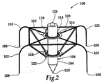
- FIG. 2 is a perspective representation of subsea repeater 100 of the present invention.
- Subsea repeater 100 includes a plurality of E-field probes 102 and an H-field probe 104 disposed within housing 106.
- E-field probes 102 may be constructed from a conductive rod or tubing including metals such as steel, copper or a copper clad.
- E-field probes 102 each have an end 106 that inserted through sea floor 16 to extend into the earth such that electromagnetic wave fronts, such as electromagnetic wave fronts 46 of Figure 1, may be received by E-field probes 102 without crossing the boundary between the sea and sea floor 16.
- E-field probes 102 pickup the E-field component of electromagnetic wave fronts 46.
- Transmitter 330 may be an acoustic or an electromagnetic transmitter such as acoustic modem 54 or E-field probes 50 of subsea repeater 48 of Figure 1.
- transmitter 300 may transform the electrical signal into an electromagnetic signal, such as electromagnetic wave fronts 66, which are radiated into the earth when transmitter 300 is an electromagnetic transmitter.
- transmitter 300 may transform the electrical signal into acoustic waves 56 that are transmitted through the sea when transmitter 300 is an acoustic modem.
Abstract
Description
- This invention relates in general to downhole telemetry and, in particular to, an apparatus and method for telemetry of information between surface equipment and downhole equipment through the sea and vice versa.
- Although the background of the invention will be described in connection with transmitting downhole data to the surface during measurements while drilling (MWD), it should be noted that the principles of the present invention are applicable not only during drilling, but throughout the life of a wellbore including, but not limited to, during logging, testing, completing and producing the well.
- Heretofore, in this field, a variety of communication and transmission techniques have been attempted to provide real time data from the vicinity of the bit to the surface during drilling. The utilization of MWD with real time data transmission provides substantial benefits during a drilling operation. For example, continuous monitoring of downhole conditions allows for an immediate response to potential well control problems and improves mud programs.
- Measurement of parameters such as bit weight, torque, wear and bearing condition in real time provides for a more efficient drilling operation. In fact, faster penetration rates, better trip planning, reduced equipment failures, fewer delays for directional surveys, and the elimination of a need to interrupt drilling for abnormal pressure detection is achievable using MWD techniques.
- At present, there are four major categories of telemetry systems that have been used in an attempt to provide real time data from the vicinity of the drill bit to the surface, namely mud pressure pulses, insulated conductors, acoustics and electromagnetic waves.
- In a mud pressure pulse system, the resistance of mud flow through a drill string is modulated by means of a valve and control mechanism mounted in a special drill collar near the bit. This type of system typically transmits at 1 bit per second as the pressure pulse travels up the mud column at or near the velocity of sound in the mud. It has been found, however, that the rate of transmission of measurements is relatively slow due to pulse spreading, modulation rate limitations, and other disruptive limitations such as the requirement of mud flow.
- Insulated conductors, or hard wire connection from the bit to the surface, is an alternative method for establishing downhole communications. This type of system is capable of a high data rate and two way communication is possible. It has been found, however, that this type of system requires a special drill pipe and special tool joint connectors which substantially increase the cost of a drilling operation. Also, these systems are prone to failure as a result of the abrasive conditions of the mud system and the wear caused by the rotation of the drill string.
- Acoustic systems have provided a third alternative. Typically, an acoustic signal is generated near the bit and is transmitted through the drill pipe, mud column or the earth. It has been found, however, that the very low intensity of the signal which can be generated downhole, along with the acoustic noise generated by the drilling system, makes signal detection difficult. Reflective and refractive interference resulting from changing diameters and thread makeup at the tool joints compounds the signal attenuation problem for drill pipe transmission.
- The fourth technique used to telemeter downhole data to the surface uses the transmission of electromagnetic waves through the earth. A current carrying downhole data is input to a toroid or collar positioned adjacent to the drill bit or input directly to the drill string. An electromagnetic receiver is inserted into the ground at the surface where the electromagnetic data is picked up and recorded. It has been found, however, that in offshore applications, the boundary between the sea and the sea floor has a nonuniform and unexpected electrical discontinuity. Conventional electromagnetic systems are, therefore, unable to effectively pickup or receive the electromagnetic signals at the boundary between the sea and the sea floor. Additionally, it has been found that conventional electromagnetic systems are unable to effectively transmit the electromagnetic signals through sea water due to the conductivity of sea water and the boundary layer between the sea and air.
- Therefore, a need has arisen for a system that is capable of telemetering real time data from the vicinity of the drill bit in a deep or noisy well using electromagnetic waves to carry the information to the sea floor. A need has also arisen for an apparatus that is capable receiving an electromagnetic signal carrying information at the sea floor and retransmitting the information to the surface through the sea.
- The present invention disclosed herein comprises a subsea repeater that receives and retransmits information between downhole equipment and surface equipment. The subsea repeater of the present invention provides for real time communication between downhole equipment and surface equipment using electromagnetic waves to carry the information through the earth and acoustic waves to carry information through the sea.
- The subsea repeater of the present invention comprises an electromagnetic receiver that receives an electromagnetic signal carrying information that may be generated by a downhole device. The information may include drilling parameters such as bit weight, torque, wear and bearing or may include reservoir parameters such as pressure, temperature, porosity, and resistivity as well as distribution, saturation, depletion and movement of oil, gas and water. In addition, the information may include operating parameters of downhole equipment such as the position or orientation of packers, sleeves and valves.
- The electromagnetic receiver may include an H-field probe having an end that is insertable into the earth and at least one E-field probe having an end that is insertable into the earth such that the subsea repeater may pick up the H-field component or the E-field component of the electromagnetic signal or both. The electromagnetic receiver transforms the electromagnetic signal carrying information into an electrical signal that is fed to an electronics package for processing and storing the information.
- After a specified period of time, such as once an hour during a drilling operation or once a day during a production operation, the information stored in the electronics package is forwarded to an acoustic transmitter. The acoustic transmitter transforms the electrical signal into an acoustic signal that retransmits the information to the surface, through the sea. The acoustic transmitter may transmit the information using, for example, frequency shift keying or multiple frequency shift keying.
- The subsea repeater of the present invention may also include an acoustic receiver that receives an acoustic signal carrying information that may be generated by a surface device and transmitted through the sea. The information may include commands to obtain the aforementioned drilling, reservoir or operating parameters or may include commands to change the operation state of a downhole device.
- The acoustic receiver transforms the acoustic signal into an electrical signal that is fed to the electronics package for processing and storing the information. The information stored in the electronics package is then forwarded to an electromagnetic transmitter that transforms the electrical signal into an electromagnetic signal that is radiated into the earth and is pickup by a downhole device.
- According to one aspect of the invention there is provided a subsea repeater apparatus for communicating information between surface equipment and downhole equipment comprising: an electromagnetic receiver receiving an electromagnetic signal carrying the information generated by the downhole equipment; and an acoustic transmitter operably connected to the electromagnetic receiver, the acoustic transmitter acoustically retransmitting the information to the surface equipment through the sea.
- The electromagnetic receiver may further comprises an H-field probe having an end that is insertable into the earth and/or at least one E-field probe having an end that is insertable into the earth.
- In an embodiment, the apparatus further comprises an electronics package operably connected to the electromagnetic receiver and the acoustic transmitter. The electronics package may further include a storage device for storing the information. The electronics package may process the information.
- The apparatus as recited in claim 1 wherein the acoustic transmitter may retransmit the information using frequency shift keying or multiple frequency shift keying.
- According to another aspect of the invention there is provided a subsea repeater apparatus for communicating information between surface equipment and downhole equipment comprising: an acoustic receiver receiving an acoustic signal carrying the information generated by the surface equipment through the sea; and an electromagnetic transmitter operably connected to the acoustic receiver, the electromagnetic transmitter retransmitting the information to the downhole equipment by radiating electromagnetic waves into the earth.
- The information in the acoustic signal may be transmitted using frequency shift keying or multiple frequency shift keying.
- In an embodiment, the apparatus further comprises an electronics package operably connected to the acoustic receiver and the electromagnetic transmitter. The electronics package may further include a storage device for storing the information. The electronics package may process the information.
- The electromagnetic transmitter may further comprise at least one electrically conductive probe having an end that is insertable into the earth.
- According to another aspect of the invention there is provided a subsea repeater apparatus for communicating information between surface equipment and downhole equipment comprising: an electromagnetic receiver receiving an electromagnetic signal carrying the information generated by the downhole equipment and transforming the electromagnetic signal into an electrical signal; an electronics package electrically connected to the electromagnetic receiver, the electronics package processing the electrical signal; and an acoustic transmitter electrically connected to the electronics package, the acoustic transmitter transforming the electrical signal into an acoustic signal and acoustically retransmitting the information to the surface equipment through the sea.
- The electromagnetic receiver may further comprise an H-field probe having an end that is insertable into the earth and/or at least one E-field probe having an end that is insertable into the earth. An electronics package as described above may also be included.
- The acoustic transmitter may retransmit the information using frequency shift keying or multiple frequency shift keying.
- According to another aspect of the invention there is provided a method for communicating information between surface equipment and downhole equipment comprising the steps of: receiving an electromagnetic signal carrying the information generated by the downhole equipment; and acoustically retransmitting the information to the surface equipment through the sea.
- The step of receiving an electromagnetic signal may further comprises receiving the H-field component of the electromagnetic signal with an H-field probe having an end that is insertable into the earth and/or receiving the E-field component of the electromagnetic signal with at least one E-field probe having an end that is insertable into the earth.
- The method may further comprise the step of transforming the electromagnetic signal into an electrical signal. The method may further comprise the step of storing the information in the electrical signal in an electronics package.
- The method may further comprise the step of transforming the electrical signal into an acoustic signal.
- The step of acoustically retransmitting the information may further comprise using frequency shift keying or multiple frequency shift keying.
- According to another aspect of the invention there is provided a method for communicating information between surface equipment and downhole equipment comprising the steps of: receiving an electromagnetic signal carrying the information generated by the downhole equipment through the earth; transforming the electromagnetic signal into an electrical signal; processing the information in the electrical signal in an electronics package; transforming the electrical signal into an acoustic signal; and acoustically retransmitting the information to the surface equipment through the sea.
- According to another aspect of the invention there is provided a method for communicating information between surface equipment and downhole equipment comprising the steps of: receiving an acoustic signal carrying the information generated by the surface equipment through the sea; and retransmitting the information to the downhole equipment by radiating electromagnetic wave into the earth.
- The acoustic signal may be transmitted using frequency shift keying or multiple frequency shift keying.
- The method may further comprise the step of transforming the acoustic signal into an electrical signal.
- The information in the electrical signal may be processed in an electronics package. The information may be stored in the electrical signal in an electronics package.
- The method may further comprise the step of transforming the electrical signal into an electromagnetic signal.
- Reference is now made to the accompanying drawings, in which:
- Figure 1 is a schematic illustration of an offshore oil or gas drilling platform operating an embodiment of a subsea repeater according to the present invention;
- Figure 2 is a schematic illustration of an embodiment of a subsea repeater according to the present invention; and
- Figure 3 is a block diagram of an embodiment of a signal processing method used by a subsea repeater according to the present invention.
-
- Referring to Figure 1, a subsea repeater in use during an offshore drilling operation is schematically illustrated and generally designated 10. A
semi-submergible platform 12 is centered over a submerged oil andgas formation 14 located belowsea floor 16. Asubsea conduit 18 extends fromdeck 20 ofplatform 12 to awellhead installation 22 includingblowout preventers 24.Platform 12 has ahoisting apparatus 26 and aderrick 28 for raising and lowering drill string 30, includingdrill bit 32. - In a typical drilling operation,
drill bit 32 is rotated by drill string 30, such thatdrill bit 32 penetrates through the various earth strata, formingwellbore 38. Measurement of parameters such as bit weight, torque, wear and bearing conditions ofdrill bit 32 may be obtained bysensors 40 located in the vicinity ofdrill bit 32. Additionally, parameters such as pressure and temperature as well as a variety of other environmental and formation information may be obtained bysensors 40. The signal generated bysensors 40 may typically be in the form of pulse width data, or the like, which must be converted to digital data before electromagnetic transmission in the present system. The signal generated bysensors 40 is passed into anelectronics package 42 including an analog to digital converter which converts the analog signal to a digital code utilizing 1's and 0's for information transmission. -
Electronics package 42 may also include electronic devices such as an on/off control, a modulator, a microprocessor, memory and amplifiers.Electronics package 42 is powered by a battery pack which may include a plurality of nickel cadmium or lithium batteries which are configured to provide proper operating voltage and current. - Once the
electronics package 42 establishes the frequency, power and phase output of the information,electronics package 42 feeds the information totransmitter 44.Transmitter 44 may be a direct connect type transmitter that utilizes an output voltage applied between two electrical terminals that are electrically isolated from one another to generateelectromagnetic wave fronts 46.Electromagnetic wave fronts 46 radiate into the earth carrying the information obtained bysensors 40. - Alternatively,
transmitter 44 may include a magnetically permeable annular core, a plurality of primary electrical conductor windings and a plurality of secondary electrical conductor windings which are wrapped around the annular core. Collectively, the annular core, the primary windings and the secondary windings serve to approximate an electrical transformer which generateselectromagnetic wave fronts 46. -
Electromagnetic wave fronts 46 travel through the earth and are received bysubsea repeater 48 located onsea floor 16.Subsea repeater 48 may detect either the electrical field (E-field) component ofelectromagnetic wave fronts 46, the magnetic field (H-field) component ofelectromagnetic wave fronts 46 or both usingE-field probes 50 and H-field probe 52 or both. Aselectromagnetic wave fronts 46 reachsubsea repeater 48, a current is induced insubsea repeater 48 that carries the information originally obtained bysensors 40. The current is fed to an electronics package withinsubsea repeater 48 that may include a variety of electronic devices such as a preamplifier, a limiter, filters, shift registers, comparators and amplifiers as will be further discussed with reference to Figure 3. The electronics package cleans up and amplifies the signal to reconstruct the original waveform, compensating for losses and distortion occurring during the transmission ofelectromagnetic wave fronts 46 through the earth. - The electronics package may include a comparator for comparing the relative strength and clarity of the H-field component versus the E-field component of
electromagnetic wave fronts 46. The electronics package may then select the stronger of the two signals for retransmission. Alternatively, the two signals may be electronically filtered and combined to produce a hybrid signal for retransmission. Also, it should be noted that the H-field component and the E-field component ofelectromagnetic wave fronts 46 received bysubsea repeater 48 may be compared to determined whether both signals contain the identical information as a check of the validity of the transmitted data. - After the electrical signal has been processed, it may be forwarded to
acoustic modem 54 that will transform the electrical signal intoacoustic waves 56. Alternatively, the information originally obtained bysensors 40 may be stored in memory insubsea repeater 48 for a predetermined period of time prior to forwarding the electrical signal toacoustic modem 54. For example, in the drilling operation as depicted in Figure 1, the information may be transmitted fromacoustic modem 54 on a periodic basis such as every hour. In a production operation, however, the information may be stored in the memory ofsubsea repeater 48 for twelve hours or twenty-four hours or even longer prior to transmission byacoustic modem 54. Thus, as should be apparent to those skilled in the art, that the length of time between transmissions fromacoustic modem 54 will depend upon the amount of information transmitted fromsensors 40 and the amount of memory available insubsea repeater 48. In addition, it should be noted thatsubsea repeater 48 may simply process and forward the information that is received without storing the information in memory. - The information may be encoded into
acoustic waves 56 byacoustic modem 54 using, for example, frequency shift keying (FSK) or multiple frequency shift keying (MFSK). Using FSK,acoustic modem 54 converts the electrical signal from a digital format into an analog format by representing the digital values with different frequencies within a defined range. Using the FSK technique, the 0's and 1's of the digital information are represented by discreet frequency pulses using frequency f1 for the 0's and frequency f2 for the 1's. Each frequency pulse, f1 or f2, represents one data bit. Using FSK may provide reliable data transmission through the sea in the range of 40 baud. The data transfer rate is limited by transmission of only one bit at a time along with the need to have intervals between transmissions to eliminate ambiguities caused by the hostile sea environment. - Alternatively,
acoustic modem 54 may transmit data using MFSK. MFSK modulation improves the data transmission rate by simultaneously broadcasting multiple data bytes. MFSK utilizes a group of four frequencies to represent the first two bits of the first byte. The next higher group of frequencies is used for the next two positions. By transmitting more than one data bit simultaneously, the data transfer rate is dramatically increased. For example, in an application using the FSK technique to provide reliable transmission of data at 40 baud, using the MFSK technique would achieve reliable transmission of data at 1,200 baud, allowing data collection to be accomplished in 1/30th of the time it would take with FSK. Additionally, when the conditions of the sea are such that high error rates are occurring, the MFSK technique can be used to transmit two copies of each data bit so thatsurface installation 60 may perform error detection and correction while having data transferred at, for example, 600 baud. - Thus, using FSK, MFSK or similar technique,
acoustic waves 56 are transmitted through the sea carrying the information originally obtained bysensors 40.Acoustic waves 56 are then picked up byacoustic modem 58 and forwarded to surfaceinstallation 60 viaelectric wire 62.Surface installation 60 may include a computer system that processes, stores and displays the information originally obtained bysensors 40.Surface installation 60 may include a peripheral computer or work station with a processor, memory and audio visual capabilities.Surface installation 60 includes a power source for producing the necessary energy to operatesurface installation 60 and may also provide the power necessary to operateacoustic modem 58.Electric wire 62 may be connected to surfaceinstallation 60 using an RS-232 interface. -
Subsea repeater 58 of the present invention may also be used as a downlink to communicate information fromsurface installation 60 to a downhole device. For example, during a production operation,surface installation 60 may be used to request downhole pressure, temperature or flow rate information fromformation 14 by sendingacoustic waves 64 through the sea fromacoustic modem 58.Acoustic waves 64 will be received atsubsea repeater 48 byacoustic modem 54.Acoustic waves 64 may use FSK or MFSK as described above to carry the information.Acoustic modem 54 will transformacoustic waves 64 into an electrical signal that is passed on to the electronics package ofsubsea repeater 48 and processed as described above.Subsea repeater 48 may then generateelectromagnetic wave fronts 66 to retransmit the information originally generated bysurface installation 60. Sensors, such assensors 40, located nearformation 14 receive this request and obtain the appropriate information which would then be returned tosurface installation 60 viaelectromagnetic wave fronts 46 andacoustic waves 56 as described above. - Although Figure 1 has been described with reference to
acoustic modem 58 in communication withsurface installation 60 onplatform 12, it should be noted by one skilled in the art thatacoustic modem 58 is equally well-suited for receiving and transmitting acoustic waves such asacoustic waves acoustic modem 58 may be attached to a ship or a crew boat that periodically travels to the remote well installation to request and obtain information relating to that remote well. - Additionally, it should be noted by one skilled in the art that subsea
repeater 48 of the present invention is may be used in conjunction with downhole repeaters in deep or noisy well application whereinsubsea repeater 48 may not be within the range ofelectromagnetic wave front 46. - Figure 2 is a perspective representation of
subsea repeater 100 of the present invention.Subsea repeater 100 includes a plurality ofE-field probes 102 and an H-field probe 104 disposed withinhousing 106.E-field probes 102 may be constructed from a conductive rod or tubing including metals such as steel, copper or a copper clad.E-field probes 102 each have anend 106 that inserted throughsea floor 16 to extend into the earth such that electromagnetic wave fronts, such aselectromagnetic wave fronts 46 of Figure 1, may be received byE-field probes 102 without crossing the boundary between the sea andsea floor 16.E-field probes 102 pickup the E-field component ofelectromagnetic wave fronts 46. - H-
field probe 104 ofsubsea repeater 100 has anend 108 that is inserted throughsea floor 16 into the earth such thatelectromagnetic wave fronts 46 are received by H-field probe 104 beforeelectromagnetic wave fronts 46 cross through the boundary ofsea floor 16 and the sea. H-field probe 104 includes one or more magnetometers for detecting the H-field component ofelectromagnetic wave fronts 46. -
Subsea repeater 100 includes aninsulated ring 112 that attachesE-field probes 102 tohousing 106. Insulated ring 84 includes an electricallyconductive ring 114 and adielectric ring 116. The electricallyconductive ring 114 is attached toE-field probes 102 to provide an electrically conductive path betweenE-field probes 102 and an electronics package disposed withinhousing 106 viaelectrical cable 118 such that the information carried in the E-field component ofelectromagnetic wave fronts 46 may be process as will be discussed with reference to Figure 3.Dielectric ring 116 creates a non-conductive region betweenconductive ring 114 andhousing 106. -
Subsea repeater 100 may include aninsulated cradle 120 that is disposed betweenE-field probes 102 andhousing 106.Insulated cradle 120 provides structural support toE-field probes 102 to prevent relative translational or rotational motion betweenE-field probes 102 andhousing 106.Insulated cradle 120 may be attached tohousing 106 using aninsulated ring 122 that may include adielectric ring 124. - The E-field component of
electromagnetic wave fronts 46 generates a current in E-field probes 102. The H-field component ofelectromagnetic wave fronts 46 generates a current in H-field probe 104. These two currents are passed on to the electronics package disposed withinhousing 106 as will be more fully described with reference to Figure 3. The electronics package may include a comparator for comparing the relative strength and clarity of the H-field component and the E-field component ofelectromagnetic wave fronts 46. The electronics package may then select the stronger of the two signals for retransmission. Additionally, the electronics package may compare the H-field component and the E-field component ofelectromagnetic wave fronts 46 to determine whether both signals carry the identical information as a check of the validity of the transmitted data. After one or both of the electric signals are processed, the information may be stored bysubsea repeater 100 in memory. While this information is retained in memory, additionalelectromagnetic wave fronts 46 carrying information may be received and stored bysubsea repeater 100. At a predetermined time, the electronics package generates an electrical signal that is passed on toacoustic modem 126. Using FSK, MFSK or other suitable techniques, the information is then transmitted through the sea byacoustic modem 126. -
Acoustic modem 126 may also receive acoustic signals, such asacoustic waves 64 of Figure 1, whensubsea repeater 100 serves as a downlink.Acoustic modem 126 transformsacoustic waves 64 into an electrical signal that is passed on to the electronics package disposed inhousing 106. The electronics package processes the electrical signal as will be more fully described with reference to Figure 3 below. After processing, the electronics package generates a current in one or more of the E-field probes 102 that in turn generateselectromagnetic wave fronts 66 that propagate the information through the earth to a downhole location. - Turning now to Figure 3, one embodiment of the method for processing the electrical signal within a
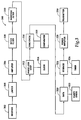
subsea repeater 48 is described.Method 300 provides for digital processing of the information carried in the electrical signal that is generated byreceiver 302 which may be an acoustic or an electromagnetic receiver such asacoustic modem 54, E-field probes 50 or H-field probe 52 of Figure 1.Limiter 304 receives the electrical signal fromreceiver 302.Limiter 304 may include a pair of diodes for attenuating the noise in the electrical signal to a predetermined range, such as between about .3 and .8 volts. The electrical signal is then passed toamplifier 306 which may amplify the electrical signal to a predetermined voltage suitable of circuit logic, such as five volts. The electrical signal is then passed through anotch filter 308 to shunt noise at a predetermined frequency, such as 60 hertz which is a typical frequency for noise in an offshore application in the United States whereas a European application may have a 50 hertz notch filter. The electrical signal then enters abandpass filter 310 to eliminate unwanted frequencies above and below the desired frequency and to recreate a signal having the original frequency, for example, two hertz. - The electrical signal is then fed through a
phase lock loop 312 that is controlled by aprecision clock 314 to assure that the electrical signal which passes throughbandpass filter 310 has the proper frequency and is not simply noise. As the electrical signal will include a certain amount of carrier frequency,phase lock loop 312 is able to verify that the received signal is, in fact, a signal carrying information to be retransmitted. The electrical signal then enters a series of shift registers that perform a variety of error checking features. -
Sync check 316 reads, for example, the first six bits of the information carried in the electrical signal. These first six bits are compared with six bits that are stored incomparator 318 to determine whether the electrical signal is carrying the type of information intended for a subsea repeater such assubsea repeater 48 of Figure 1. For example, the first six bits in the preamble to the information carried inelectromagnetic wave fronts 46 must carry the code stored incomparator 318 in order for the electrical signal to pass throughsync check 316. - If the first six bits in the preamble correspond with that in
comparator 318, the electrical signal is shifted into adata register 320 which is in communication with aparity check 322 to analyze the information carried in the electrical signal for errors and to assure that noise has not infiltrated and abrogated the data stream by checking the parity of the data stream. If no errors are detected, the electrical signal is shifted into one or more storage registers 324. Storage registers 324 receive the entire sequence of information and may pass the electrical signal directly intopower amplifier 328 for retransmission bytransmitter 330 which may typically occur whensubsea repeater 48 serves as a downlink. Alternatively, the information may be stored for a specified period of time determined bytimer 326 prior to sending the signal topower amplifier 328. For example,subsea repeater 48 may be used to store formation information for a twelve or twenty-four hour period between transmissions to the surface. -
Transmitter 330 may be an acoustic or an electromagnetic transmitter such asacoustic modem 54 orE-field probes 50 ofsubsea repeater 48 of Figure 1. For example,transmitter 300 may transform the electrical signal into an electromagnetic signal, such aselectromagnetic wave fronts 66, which are radiated into the earth whentransmitter 300 is an electromagnetic transmitter. Alternatively,transmitter 300 may transform the electrical signal intoacoustic waves 56 that are transmitted through the sea whentransmitter 300 is an acoustic modem. - Although Figure 3 has described
sync check 316, data register 320 andstorage register 324 as shift registers, it should be apparent to those skilled in the art that alternate electronic devices may be used for error checking and storage including, but not limited to, random access memory, read only memory, erasable programmable read only memory and a microprocessor. - It will be appreciated that the invention described above may be modified.
Claims (10)
- A subsea repeater apparatus (48) for communicating information between surface equipment (60) and downhole equipment (44), comprising: an electromagnetic receiver receiving an electromagnetic signal (46) carrying the information generated by the downhole equipment (44); and an acoustic transmitter (54) operably connected to the electromagnetic receiver, the acoustic transmitter (54) acoustically retransmitting the information to the surface equipment (60) through the sea.
- Apparatus (48) according to claim 1 wherein the electromagnetic receiver further comprises an H-field probe (52) having an end that is insertable into the earth.
- Apparatus (48) according to claim 1 or 2, wherein the electromagnetic receiver further comprises at least one E-field probe (50) having an end that is insertable into the earth.
- Apparatus (48) according to claim 1, 2 or 3, further comprising an electronics package operably connected to the electromagnetic receiver and the acoustic transmitter (54), the electronics package processing the information and including a storage device for storing the information, and wherein the acoustic transmitter (54) retransmits the information using frequency shift keying or multiple frequency shift keying.
- A subsea repeater apparatus (48) for communicating information between surface equipment and downhole equipment, comprising: an acoustic receiver (54) receiving an acoustic (64) signal carrying the information generated by the surface equipment (60) through the sea; and an electromagnetic transmitter operably connected to the acoustic receiver (54), the electromagnetic transmitter retransmitting the information to the downhole equipment by radiating electromagnetic waves (66) into the earth.
- Apparatus (48) according to claim 5, wherein the information in the acoustic signal is transmitted using frequency shift keying.
- Apparatus according to claim 5, wherein the information in the acoustic signal is transmitted using multiple frequency shift keying.
- Apparatus according to claim 5, 6 or 7, further comprising an electronics package operably connected to the acoustic receiver (54) and the electromagnetic transmitter.
- A method for communicating information between surface equipment (60) and downhole equipment (44), comprising the steps of: receiving an electromagnetic signal (46) carrying the information generated by the downhole equipment (44); and acoustically retransmitting the information to the surface equipment (60) through the sea.
- A method for communicating information between surface equipment (60) and downhole equipment (44), comprising the steps of: receiving an acoustic signal (64) carrying the information generated by the surface equipment (60) through the sea; and retransmitting the information to the downhole equipment (44) by radiating electromagnetic waves (66) into the earth.
Applications Claiming Priority (2)
| Application Number | Priority Date | Filing Date | Title |
|---|---|---|---|
| US08/987,991 US6018501A (en) | 1997-12-10 | 1997-12-10 | Subsea repeater and method for use of the same |
| US987991 | 1997-12-10 |
Publications (2)
| Publication Number | Publication Date |
|---|---|
| EP0922836A1 true EP0922836A1 (en) | 1999-06-16 |
| EP0922836B1 EP0922836B1 (en) | 2006-03-29 |
Family
ID=25533761
Family Applications (1)
| Application Number | Title | Priority Date | Filing Date |
|---|---|---|---|
| EP98310134A Expired - Lifetime EP0922836B1 (en) | 1997-12-10 | 1998-12-10 | Subsea repeater and method for use of the same |
Country Status (3)
| Country | Link |
|---|---|
| US (1) | US6018501A (en) |
| EP (1) | EP0922836B1 (en) |
| DE (1) | DE69834015D1 (en) |
Cited By (14)
| Publication number | Priority date | Publication date | Assignee | Title |
|---|---|---|---|---|
| EP0932054A2 (en) * | 1998-01-27 | 1999-07-28 | Halliburton Energy Services, Inc. | Downhole telemetry system and method for remote communication |
| GB2377131A (en) * | 2001-04-23 | 2002-12-31 | Schlumberger Holdings | Subsea communications |
| GB2382603A (en) * | 2001-11-28 | 2003-06-04 | Halliburton Energy Serv Inc | Electromagnetic telemetry actuated firing system for well perforating gun |
| FR2840951A1 (en) * | 2002-06-13 | 2003-12-19 | Inst Francais Du Petrole | Instrumentation assembly for deep water drilling installation, has central processing unit connected to multiple modules, series of detectors and assembly measuring floater position |
| WO2004113676A2 (en) * | 2003-06-16 | 2004-12-29 | Quantx Wellbore Instrumentation | A sensor system and method of communicating data between a downhole device on a remote location |
| EP2019524A2 (en) * | 2007-07-25 | 2009-01-28 | Vetco Gray Controls Limited | Electronics module |
| GB2478761A (en) * | 2010-03-17 | 2011-09-21 | Wireless Fibre Systems Ltd | Wireless Auxiliary Monitoring and Control System for Remote Underwater Installation |
| US8305227B2 (en) | 2005-06-15 | 2012-11-06 | Wfs Technologies Ltd. | Wireless auxiliary monitoring and control system for an underwater installation |
| US8890710B2 (en) | 2008-07-31 | 2014-11-18 | Halliburton Energy Services, Inc. | Method and system of an electromagnetic telemetry |
| WO2014193616A3 (en) * | 2013-05-29 | 2015-04-16 | Vetco Gray Inc. | Apparatus and method for measuring inclination in subsea running, setting and testing tools |
| WO2015077552A3 (en) * | 2013-11-22 | 2015-09-03 | Aps Technology, Inc. | System, apparatus, and method for drilling |
| US20150247401A1 (en) * | 2014-03-03 | 2015-09-03 | Aps Technology, Inc. | Drilling System and Electromagnetic Telemetry Tool With an Electrical Connector Assembly and Associated Methods |
| US9790784B2 (en) | 2014-05-20 | 2017-10-17 | Aps Technology, Inc. | Telemetry system, current sensor, and related methods for a drilling system |
| US9976413B2 (en) | 2015-02-20 | 2018-05-22 | Aps Technology, Inc. | Pressure locking device for downhole tools |
Families Citing this family (50)
| Publication number | Priority date | Publication date | Assignee | Title |
|---|---|---|---|---|
| US6177882B1 (en) * | 1997-12-01 | 2001-01-23 | Halliburton Energy Services, Inc. | Electromagnetic-to-acoustic and acoustic-to-electromagnetic repeaters and methods for use of same |
| US6333699B1 (en) | 1998-08-28 | 2001-12-25 | Marathon Oil Company | Method and apparatus for determining position in a pipe |
| US7283061B1 (en) | 1998-08-28 | 2007-10-16 | Marathon Oil Company | Method and system for performing operations and for improving production in wells |
| US20040239521A1 (en) | 2001-12-21 | 2004-12-02 | Zierolf Joseph A. | Method and apparatus for determining position in a pipe |
| US6386288B1 (en) | 1999-04-27 | 2002-05-14 | Marathon Oil Company | Casing conveyed perforating process and apparatus |
| US6536524B1 (en) | 1999-04-27 | 2003-03-25 | Marathon Oil Company | Method and system for performing a casing conveyed perforating process and other operations in wells |
| US6727827B1 (en) | 1999-08-30 | 2004-04-27 | Schlumberger Technology Corporation | Measurement while drilling electromagnetic telemetry system using a fixed downhole receiver |
| US7014100B2 (en) * | 2001-04-27 | 2006-03-21 | Marathon Oil Company | Process and assembly for identifying and tracking assets |
| US6702025B2 (en) | 2002-02-11 | 2004-03-09 | Halliburton Energy Services, Inc. | Hydraulic control assembly for actuating a hydraulically controllable downhole device and method for use of same |
| US7451809B2 (en) * | 2002-10-11 | 2008-11-18 | Weatherford/Lamb, Inc. | Apparatus and methods for utilizing a downhole deployment valve |
| US7178600B2 (en) | 2002-11-05 | 2007-02-20 | Weatherford/Lamb, Inc. | Apparatus and methods for utilizing a downhole deployment valve |
| US7255173B2 (en) * | 2002-11-05 | 2007-08-14 | Weatherford/Lamb, Inc. | Instrumentation for a downhole deployment valve |
| US7219729B2 (en) * | 2002-11-05 | 2007-05-22 | Weatherford/Lamb, Inc. | Permanent downhole deployment of optical sensors |
| US7350590B2 (en) * | 2002-11-05 | 2008-04-01 | Weatherford/Lamb, Inc. | Instrumentation for a downhole deployment valve |
| US7063148B2 (en) * | 2003-12-01 | 2006-06-20 | Marathon Oil Company | Method and system for transmitting signals through a metal tubular |
| US7080699B2 (en) * | 2004-01-29 | 2006-07-25 | Schlumberger Technology Corporation | Wellbore communication system |
| EP1577683B1 (en) * | 2004-03-16 | 2008-12-17 | Services Petroliers Schlumberger | Characterizing properties of a geological formation by coupled acoustic and electromagnetic measurements |
| US20070234789A1 (en) * | 2006-04-05 | 2007-10-11 | Gerard Glasbergen | Fluid distribution determination and optimization with real time temperature measurement |
| US7557492B2 (en) | 2006-07-24 | 2009-07-07 | Halliburton Energy Services, Inc. | Thermal expansion matching for acoustic telemetry system |
| US7595737B2 (en) * | 2006-07-24 | 2009-09-29 | Halliburton Energy Services, Inc. | Shear coupled acoustic telemetry system |
| US8540027B2 (en) * | 2006-08-31 | 2013-09-24 | Geodynamics, Inc. | Method and apparatus for selective down hole fluid communication |
| US20100182161A1 (en) * | 2007-04-28 | 2010-07-22 | Halliburton Energy Services, Inc. | Wireless telemetry repeater systems and methods |
| US9194227B2 (en) * | 2008-03-07 | 2015-11-24 | Marathon Oil Company | Systems, assemblies and processes for controlling tools in a wellbore |
| US10119377B2 (en) * | 2008-03-07 | 2018-11-06 | Weatherford Technology Holdings, Llc | Systems, assemblies and processes for controlling tools in a well bore |
| WO2009143409A2 (en) * | 2008-05-23 | 2009-11-26 | Martin Scientific, Llc | Reliable downhole data transmission system |
| US20100013663A1 (en) | 2008-07-16 | 2010-01-21 | Halliburton Energy Services, Inc. | Downhole Telemetry System Using an Optically Transmissive Fluid Media and Method for Use of Same |
| US9234981B2 (en) * | 2009-07-31 | 2016-01-12 | Halliburton Energy Services, Inc. | Exploitation of sea floor rig structures to enhance measurement while drilling telemetry data |
| US8850899B2 (en) | 2010-04-15 | 2014-10-07 | Marathon Oil Company | Production logging processes and systems |
| US8930143B2 (en) | 2010-07-14 | 2015-01-06 | Halliburton Energy Services, Inc. | Resolution enhancement for subterranean well distributed optical measurements |
| US8584519B2 (en) * | 2010-07-19 | 2013-11-19 | Halliburton Energy Services, Inc. | Communication through an enclosure of a line |
| GB201012175D0 (en) * | 2010-07-20 | 2010-09-01 | Metrol Tech Ltd | Procedure and mechanisms |
| GB201012176D0 (en) * | 2010-07-20 | 2010-09-01 | Metrol Tech Ltd | Well |
| US9175515B2 (en) * | 2010-12-23 | 2015-11-03 | Schlumberger Technology Corporation | Wired mud motor components, methods of fabricating the same, and downhole motors incorporating the same |
| IT1403940B1 (en) * | 2011-02-16 | 2013-11-08 | Eni Spa | SYSTEM FOR DETECTION OF GEOLOGICAL FORMATIONS |
| WO2012148805A2 (en) * | 2011-04-26 | 2012-11-01 | Bp Corporation North America Inc. | Acoustic transponder for monitoring subsea measurements from an offshore well |
| EP2664743A1 (en) * | 2012-05-16 | 2013-11-20 | Services Pétroliers Schlumberger | Downhole information storage and transmission |
| US9823373B2 (en) | 2012-11-08 | 2017-11-21 | Halliburton Energy Services, Inc. | Acoustic telemetry with distributed acoustic sensing system |
| US9007231B2 (en) | 2013-01-17 | 2015-04-14 | Baker Hughes Incorporated | Synchronization of distributed measurements in a borehole |
| GB2535640B (en) | 2013-11-05 | 2020-08-19 | Halliburton Energy Services Inc | Downhole position sensor |
| GB2537494B (en) | 2013-12-23 | 2020-09-16 | Halliburton Energy Services Inc | Downhole signal repeater |
| WO2015102582A1 (en) | 2013-12-30 | 2015-07-09 | Halliburton Energy Services, Inc. | Position indicator through acoustics |
| WO2015112127A1 (en) | 2014-01-22 | 2015-07-30 | Halliburton Energy Services, Inc. | Remote tool position and tool status indication |
| CA3171421A1 (en) | 2014-06-23 | 2015-12-30 | Evolution Engineering Inc. | Optimizing downhole data communication with at bit sensors and nodes |
| BR112015030293B1 (en) * | 2014-10-01 | 2022-08-16 | Ocean Floor Geophysics, Inc | METHOD FOR MAGNETIC DATA COMPENSATION |
| GB2531032B (en) * | 2014-10-07 | 2021-01-06 | Aker Solutions Ltd | Subsea electronics module |
| WO2019093999A1 (en) * | 2017-11-08 | 2019-05-16 | Halliburton Energy Services, Inc. | Offshore downhole telemetry using sea floor cable |
| US11203927B2 (en) * | 2017-11-17 | 2021-12-21 | Exxonmobil Upstream Research Company | Method and system for performing wireless ultrasonic communications along tubular members |
| CN108832983A (en) * | 2018-06-22 | 2018-11-16 | 郑州国知网络技术有限公司 | A kind of repeater |
| BR102018069281B1 (en) * | 2018-09-21 | 2022-02-22 | Petróleo Brasileiro S.A. - Petrobras | Disconnected well monitoring system and method |
| CN111812208B (en) * | 2020-06-30 | 2024-02-06 | 中海油田服务股份有限公司 | Marine jack-up platform pile-inserting ballast monitoring device |
Citations (5)
| Publication number | Priority date | Publication date | Assignee | Title |
|---|---|---|---|---|
| US4161715A (en) * | 1977-09-02 | 1979-07-17 | Electric Power Research Institute, Inc. | Method and apparatus for measuring the interior dimensions of a hollow body |
| US4698631A (en) * | 1986-12-17 | 1987-10-06 | Hughes Tool Company | Surface acoustic wave pipe identification system |
| US4828051A (en) * | 1986-02-07 | 1989-05-09 | Comdisco Resources, Inc. | Method and apparatus for data transmission in a well using a flexible line with stiffener |
| EP0636763A2 (en) * | 1993-07-26 | 1995-02-01 | Baker Hughes Incorporated | Method and apparatus for electric/acoustic telemetry in a well |
| US5394141A (en) * | 1991-09-12 | 1995-02-28 | Geoservices | Method and apparatus for transmitting information between equipment at the bottom of a drilling or production operation and the surface |
Family Cites Families (75)
| Publication number | Priority date | Publication date | Assignee | Title |
|---|---|---|---|---|
| US2379800A (en) * | 1941-09-11 | 1945-07-03 | Texas Co | Signal transmission system |
| US2411696A (en) * | 1944-04-26 | 1946-11-26 | Stanolind Oil & Gas Co | Well signaling system |
| US3186222A (en) * | 1960-07-28 | 1965-06-01 | Mccullough Tool Co | Well signaling system |
| US3333239A (en) * | 1965-12-16 | 1967-07-25 | Pan American Petroleum Corp | Subsurface signaling technique |
| US3205477A (en) * | 1961-12-29 | 1965-09-07 | David C Kalbfell | Electroacoustical logging while drilling wells |
| US3227228A (en) * | 1963-05-24 | 1966-01-04 | Clyde E Bannister | Rotary drilling and borehole coring apparatus and method |
| US3233674A (en) * | 1963-07-22 | 1966-02-08 | Baker Oil Tools Inc | Subsurface well apparatus |
| US5029147A (en) * | 1969-02-26 | 1991-07-02 | The United States Of America As Represented By The Secretary Of The Navy | Acoustic, underwater, telemetry system |
| FR2040580A5 (en) * | 1969-04-03 | 1971-01-22 | Inst Francais Du Petrole | |
| US5583504A (en) * | 1970-04-01 | 1996-12-10 | United States Of America As Represented By The Secretary Of The Air Force | Method and system of producing phase front distortion |
| US3930220A (en) * | 1973-09-12 | 1975-12-30 | Sun Oil Co Pennsylvania | Borehole signalling by acoustic energy |
| DE2416063C3 (en) * | 1974-04-03 | 1978-03-30 | Erich 3000 Hannover Krebs | Device for measuring and wireless transmission of measured values to the earth's surface |
| CA1062336A (en) * | 1974-07-01 | 1979-09-11 | Robert K. Cross | Electromagnetic lithosphere telemetry system |
| US4065747A (en) * | 1975-11-28 | 1977-12-27 | Bunker Ramo Corporation | Acoustical underwater communication system for command control and data |
| US4019148A (en) * | 1975-12-29 | 1977-04-19 | Sperry-Sun, Inc. | Lock-in noise rejection circuit |
| US4293936A (en) * | 1976-12-30 | 1981-10-06 | Sperry-Sun, Inc. | Telemetry system |
| US4309763A (en) * | 1977-03-02 | 1982-01-05 | Refraction Technology, Inc. | Digital sonobuoy |
| US4160970A (en) * | 1977-11-25 | 1979-07-10 | Sperry Rand Corporation | Electromagnetic wave telemetry system for transmitting downhole parameters to locations thereabove |
| US4215426A (en) * | 1978-05-01 | 1980-07-29 | Frederick Klatt | Telemetry and power transmission for enclosed fluid systems |
| US4181014A (en) * | 1978-05-04 | 1980-01-01 | Scientific Drilling Controls, Inc. | Remote well signalling apparatus and methods |
| US4302757A (en) * | 1979-05-09 | 1981-11-24 | Aerospace Industrial Associates, Inc. | Bore telemetry channel of increased capacity |
| US4363137A (en) * | 1979-07-23 | 1982-12-07 | Occidental Research Corporation | Wireless telemetry with magnetic induction field |
| US4293937A (en) * | 1979-08-10 | 1981-10-06 | Sperry-Sun, Inc. | Borehole acoustic telemetry system |
| US4320473A (en) * | 1979-08-10 | 1982-03-16 | Sperry Sun, Inc. | Borehole acoustic telemetry clock synchronization system |
| US4298970A (en) * | 1979-08-10 | 1981-11-03 | Sperry-Sun, Inc. | Borehole acoustic telemetry system synchronous detector |
| DE3027755A1 (en) * | 1980-07-22 | 1982-02-11 | Siemens AG, 1000 Berlin und 8000 München | METHOD FOR MONITORING INTERIM REGENERATORS |
| US4373582A (en) * | 1980-12-22 | 1983-02-15 | Exxon Production Research Co. | Acoustically controlled electro-mechanical circulation sub |
| US4562559A (en) * | 1981-01-19 | 1985-12-31 | Nl Sperry Sun, Inc. | Borehole acoustic telemetry system with phase shifted signal |
| US4496174A (en) * | 1981-01-30 | 1985-01-29 | Tele-Drill, Inc. | Insulated drill collar gap sub assembly for a toroidal coupled telemetry system |
| US4468665A (en) * | 1981-01-30 | 1984-08-28 | Tele-Drill, Inc. | Downhole digital power amplifier for a measurements-while-drilling telemetry system |
| US4725837A (en) * | 1981-01-30 | 1988-02-16 | Tele-Drill, Inc. | Toroidal coupled telemetry apparatus |
| US4348672A (en) * | 1981-03-04 | 1982-09-07 | Tele-Drill, Inc. | Insulated drill collar gap sub assembly for a toroidal coupled telemetry system |
| US4387372A (en) * | 1981-03-19 | 1983-06-07 | Tele-Drill, Inc. | Point gap assembly for a toroidal coupled telemetry system |
| US4428073A (en) * | 1981-11-02 | 1984-01-24 | The United States Of America As Represented By The Secretary Of The Navy | Underwater depth telemetry |
| US4525715A (en) * | 1981-11-25 | 1985-06-25 | Tele-Drill, Inc. | Toroidal coupled telemetry apparatus |
| US4739325A (en) * | 1982-09-30 | 1988-04-19 | Macleod Laboratories, Inc. | Apparatus and method for down-hole EM telemetry while drilling |
| US4578675A (en) * | 1982-09-30 | 1986-03-25 | Macleod Laboratories, Inc. | Apparatus and method for logging wells while drilling |
| US4908804A (en) * | 1983-03-21 | 1990-03-13 | Develco, Inc. | Combinatorial coded telemetry in MWD |
| FR2562601B2 (en) * | 1983-05-06 | 1988-05-27 | Geoservices | DEVICE FOR TRANSMITTING SIGNALS OF A TRANSMITTER LOCATED AT LARGE DEPTH |
| US4691203A (en) * | 1983-07-01 | 1987-09-01 | Rubin Llewellyn A | Downhole telemetry apparatus and method |
| US4616702A (en) * | 1984-05-01 | 1986-10-14 | Comdisco Resources, Inc. | Tool and combined tool support and casing section for use in transmitting data up a well |
| US4599745A (en) * | 1984-05-21 | 1986-07-08 | The United States Of America As Represented By The Secretary Of The Navy | Hybrid fiber optics and radio frequency telemetry apparatus for acquiring data from an underwater environment |
| NO844838L (en) * | 1984-12-04 | 1986-06-05 | Saga Petroleum | PROCEDURE FOR REGISTERING A RELATIONSHIP BETWEEN OIL BROWN RESERVES. |
| US4617960A (en) * | 1985-05-03 | 1986-10-21 | Develco, Inc. | Verification of a surface controlled subsurface actuating device |
| IT1191903B (en) * | 1986-05-15 | 1988-03-31 | Selenia Spazio Spa | CONCATENATED CODING-DECODING SYSTEM FOR PROTECTION AGAINST DISTURBANCES OF DIGITAL TRANSMISSIONS CARRIED OUT THROUGH AN INTERMEDIATE REGENERATIVE REPEATER |
| FR2600171B1 (en) * | 1986-06-17 | 1990-10-19 | Geoservices | LARGE DEPTH TRANSMITTER ANTENNA |
| FR2606963B1 (en) * | 1986-11-14 | 1989-01-13 | Cit Alcatel | SUBMARINE REPEATER BOX |
| US4788544A (en) * | 1987-01-08 | 1988-11-29 | Hughes Tool Company - Usa | Well bore data transmission system |
| US4845493A (en) * | 1987-01-08 | 1989-07-04 | Hughes Tool Company | Well bore data transmission system with battery preserving switch |
| US4839644A (en) * | 1987-06-10 | 1989-06-13 | Schlumberger Technology Corp. | System and method for communicating signals in a cased borehole having tubing |
| US4901069A (en) * | 1987-07-16 | 1990-02-13 | Schlumberger Technology Corporation | Apparatus for electromagnetically coupling power and data signals between a first unit and a second unit and in particular between well bore apparatus and the surface |
| FR2621072B1 (en) * | 1987-09-28 | 1989-12-01 | Alsthom | ELECTROMAGNETIC INFORMATION TRANSMISSION SYSTEM FROM THE BOTTOM DURING A DRILLING AND TRANSMITTER FOR THIS SYSTEM |
| NO163578C (en) * | 1987-10-23 | 1990-06-20 | Saga Petroleum | PROCEDURE AND DEVICE FOR TRANSFER OF TARGET DATA FROM A OIL BROWN TO THE SURFACE. |
| US5268683A (en) * | 1988-09-02 | 1993-12-07 | Stolar, Inc. | Method of transmitting data from a drillhead |
| US4968978A (en) * | 1988-09-02 | 1990-11-06 | Stolar, Inc. | Long range multiple point wireless control and monitoring system |
| US5087099A (en) * | 1988-09-02 | 1992-02-11 | Stolar, Inc. | Long range multiple point wireless control and monitoring system |
| US5018114A (en) * | 1988-12-13 | 1991-05-21 | The United States Of America As Represented By The Secretary Of The Navy | Adjustable frequency diversity acoustic communications system |
| US4933640A (en) * | 1988-12-30 | 1990-06-12 | Vector Magnetics | Apparatus for locating an elongated conductive body by electromagnetic measurement while drilling |
| US5119500A (en) * | 1989-10-10 | 1992-06-02 | The United States Of America As Represented By The Secretary Of The Navy | Meteor burst communication system |
| US5047990A (en) * | 1990-06-01 | 1991-09-10 | The United States Of America As Represented By The Secretary Of The Navy | Underwater acoustic data acquisition system |
| US5160925C1 (en) * | 1991-04-17 | 2001-03-06 | Halliburton Co | Short hop communication link for downhole mwd system |
| US5130706A (en) * | 1991-04-22 | 1992-07-14 | Scientific Drilling International | Direct switching modulation for electromagnetic borehole telemetry |
| US5283768A (en) * | 1991-06-14 | 1994-02-01 | Baker Hughes Incorporated | Borehole liquid acoustic wave transducer |
| US5493288A (en) * | 1991-06-28 | 1996-02-20 | Elf Aquitaine Production | System for multidirectional information transmission between at least two units of a drilling assembly |
| NO306522B1 (en) * | 1992-01-21 | 1999-11-15 | Anadrill Int Sa | Procedure for acoustic transmission of measurement signals when measuring during drilling |
| FR2697119B1 (en) * | 1992-10-16 | 1995-01-20 | Schlumberger Services Petrol | Transmitter device with double insulating connection, intended for use in drilling. |
| US5319376A (en) * | 1992-12-01 | 1994-06-07 | Trw Inc. | Arctic submarine buoy and application methods |
| FR2699713B1 (en) * | 1992-12-17 | 1995-03-24 | Hubert Thomas | Method and device for remote control of an unmanned underwater vehicle. |
| CA2164342A1 (en) * | 1993-06-04 | 1994-12-22 | Norman C. Macleod | Method and apparatus for communicating signals from encased borehole |
| US5379034A (en) * | 1993-06-15 | 1995-01-03 | The United States Of America As Represented By The Secretary Of The Navy | Apparatus and method of radio communication from a submerged underwater vehicle |
| US5467083A (en) * | 1993-08-26 | 1995-11-14 | Electric Power Research Institute | Wireless downhole electromagnetic data transmission system and method |
| US5530358A (en) * | 1994-01-25 | 1996-06-25 | Baker Hughes, Incorporated | Method and apparatus for measurement-while-drilling utilizing improved antennas |
| NO305219B1 (en) * | 1994-03-16 | 1999-04-19 | Aker Eng As | Method and transmitter / receiver for transmitting signals via a medium in tubes or hoses |
| US5452262A (en) * | 1994-10-11 | 1995-09-19 | The United States Of America As Represented By The Secretary Of The Navy | Radio telemetry buoy for long-range communication |
| US5691712A (en) * | 1995-07-25 | 1997-11-25 | Schlumberger Technology Corporation | Multiple wellbore tool apparatus including a plurality of microprocessor implemented wellbore tools for operating a corresponding plurality of included wellbore tools and acoustic transducers in response to stimulus signals and acoustic signals |
-
1997
- 1997-12-10 US US08/987,991 patent/US6018501A/en not_active Expired - Lifetime
-
1998
- 1998-12-10 EP EP98310134A patent/EP0922836B1/en not_active Expired - Lifetime
- 1998-12-10 DE DE69834015T patent/DE69834015D1/en not_active Expired - Lifetime
Patent Citations (5)
| Publication number | Priority date | Publication date | Assignee | Title |
|---|---|---|---|---|
| US4161715A (en) * | 1977-09-02 | 1979-07-17 | Electric Power Research Institute, Inc. | Method and apparatus for measuring the interior dimensions of a hollow body |
| US4828051A (en) * | 1986-02-07 | 1989-05-09 | Comdisco Resources, Inc. | Method and apparatus for data transmission in a well using a flexible line with stiffener |
| US4698631A (en) * | 1986-12-17 | 1987-10-06 | Hughes Tool Company | Surface acoustic wave pipe identification system |
| US5394141A (en) * | 1991-09-12 | 1995-02-28 | Geoservices | Method and apparatus for transmitting information between equipment at the bottom of a drilling or production operation and the surface |
| EP0636763A2 (en) * | 1993-07-26 | 1995-02-01 | Baker Hughes Incorporated | Method and apparatus for electric/acoustic telemetry in a well |
Cited By (27)
| Publication number | Priority date | Publication date | Assignee | Title |
|---|---|---|---|---|
| EP0932054A3 (en) * | 1998-01-27 | 2000-06-14 | Halliburton Energy Services, Inc. | Downhole telemetry system and method for remote communication |
| EP0932054A2 (en) * | 1998-01-27 | 1999-07-28 | Halliburton Energy Services, Inc. | Downhole telemetry system and method for remote communication |
| GB2377131A (en) * | 2001-04-23 | 2002-12-31 | Schlumberger Holdings | Subsea communications |
| US7123162B2 (en) | 2001-04-23 | 2006-10-17 | Schlumberger Technology Corporation | Subsea communication system and technique |
| GB2377131B (en) * | 2001-04-23 | 2006-01-25 | Schlumberger Holdings | Subsea communication systems and techniques |
| GB2382603A (en) * | 2001-11-28 | 2003-06-04 | Halliburton Energy Serv Inc | Electromagnetic telemetry actuated firing system for well perforating gun |
| US6820693B2 (en) | 2001-11-28 | 2004-11-23 | Halliburton Energy Services, Inc. | Electromagnetic telemetry actuated firing system for well perforating gun |
| US7080689B2 (en) | 2002-06-13 | 2006-07-25 | Institut Francais Du Petrole | Instrumentation assembly for an offshore riser |
| FR2840951A1 (en) * | 2002-06-13 | 2003-12-19 | Inst Francais Du Petrole | Instrumentation assembly for deep water drilling installation, has central processing unit connected to multiple modules, series of detectors and assembly measuring floater position |
| GB2426163B (en) * | 2003-06-16 | 2007-08-29 | Quantx Wellbore Instrumentatio | A sensor system and method of communicating data between a downhole device and a remote device |
| GB2426163A (en) * | 2003-06-16 | 2006-11-15 | Quantx Wellbore Instrumentatio | A sensor system and method of communication data between a downhole device on a remote location |
| WO2004113676A2 (en) * | 2003-06-16 | 2004-12-29 | Quantx Wellbore Instrumentation | A sensor system and method of communicating data between a downhole device on a remote location |
| WO2004113676A3 (en) * | 2003-06-16 | 2005-05-06 | Baker Hughes Inc | A sensor system and method of communicating data between a downhole device on a remote location |
| US8305227B2 (en) | 2005-06-15 | 2012-11-06 | Wfs Technologies Ltd. | Wireless auxiliary monitoring and control system for an underwater installation |
| EP2019524A2 (en) * | 2007-07-25 | 2009-01-28 | Vetco Gray Controls Limited | Electronics module |
| EP2019524A3 (en) * | 2007-07-25 | 2011-10-19 | Vetco Gray Controls Limited | Electronics module |
| US8890710B2 (en) | 2008-07-31 | 2014-11-18 | Halliburton Energy Services, Inc. | Method and system of an electromagnetic telemetry |
| GB2478761A (en) * | 2010-03-17 | 2011-09-21 | Wireless Fibre Systems Ltd | Wireless Auxiliary Monitoring and Control System for Remote Underwater Installation |
| GB2478761B (en) * | 2010-03-17 | 2012-02-22 | Wfs Technologies Ltd | Wireless auxiliary monitoring and control system for an underwater installation |
| WO2014193616A3 (en) * | 2013-05-29 | 2015-04-16 | Vetco Gray Inc. | Apparatus and method for measuring inclination in subsea running, setting and testing tools |
| WO2015077552A3 (en) * | 2013-11-22 | 2015-09-03 | Aps Technology, Inc. | System, apparatus, and method for drilling |
| CN106030034A (en) * | 2013-11-22 | 2016-10-12 | Aps科技公司 | System, apparatus, and method for drilling |
| US10190408B2 (en) | 2013-11-22 | 2019-01-29 | Aps Technology, Inc. | System, apparatus, and method for drilling |
| US20150247401A1 (en) * | 2014-03-03 | 2015-09-03 | Aps Technology, Inc. | Drilling System and Electromagnetic Telemetry Tool With an Electrical Connector Assembly and Associated Methods |
| US9765613B2 (en) * | 2014-03-03 | 2017-09-19 | Aps Technology, Inc. | Drilling system and electromagnetic telemetry tool with an electrical connector assembly and associated methods |
| US9790784B2 (en) | 2014-05-20 | 2017-10-17 | Aps Technology, Inc. | Telemetry system, current sensor, and related methods for a drilling system |
| US9976413B2 (en) | 2015-02-20 | 2018-05-22 | Aps Technology, Inc. | Pressure locking device for downhole tools |
Also Published As
| Publication number | Publication date |
|---|---|
| DE69834015D1 (en) | 2006-05-18 |
| US6018501A (en) | 2000-01-25 |
| EP0922836B1 (en) | 2006-03-29 |
Similar Documents
| Publication | Publication Date | Title |
|---|---|---|
| US6018501A (en) | Subsea repeater and method for use of the same | |
| EP0911484B1 (en) | Electromagnetic signal repeater and method for use of same | |
| EP0919696B1 (en) | Electromagnetic and acoustic repeater and method for use of same | |
| US6177882B1 (en) | Electromagnetic-to-acoustic and acoustic-to-electromagnetic repeaters and methods for use of same | |
| US6218959B1 (en) | Fail safe downhole signal repeater | |
| EP0913555B1 (en) | Electromagnetic signal pickup device | |
| US6075461A (en) | Disposable electromagnetic signal repeater | |
| US7411517B2 (en) | Apparatus and method for providing communication between a probe and a sensor | |
| CA2455186C (en) | Filters for canceling multiple noise sources in borehole electromagnetic telemetry system | |
| EP0972909B1 (en) | Electromagnetic telemetry system | |
| JP5384109B2 (en) | Surface communication device and method used for excavation string telemetry | |
| US6781520B1 (en) | Motion sensor for noise cancellation in borehole electromagnetic telemetry system | |
| US6781521B1 (en) | Filters for canceling multiple noise sources in borehole electromagnetic telemetry system | |
| WO2002012676A1 (en) | Apparatus and method for telemetry | |
| US6208265B1 (en) | Electromagnetic signal pickup apparatus and method for use of same | |
| EP3485142B1 (en) | System for cableless bidirectional data transmission in a well for the extraction of formation fluids |
Legal Events
| Date | Code | Title | Description |
|---|---|---|---|
| PUAI | Public reference made under article 153(3) epc to a published international application that has entered the european phase |
Free format text: ORIGINAL CODE: 0009012 |
|
| AK | Designated contracting states |
Kind code of ref document: A1 Designated state(s): DE FR GB NL |
|
| AX | Request for extension of the european patent |
Free format text: AL;LT;LV;MK;RO;SI |
|
| AKX | Designation fees paid | ||
| 17P | Request for examination filed |
Effective date: 19991216 |
|
| RBV | Designated contracting states (corrected) |
Designated state(s): DE FR GB NL |
|
| REG | Reference to a national code |
Ref country code: DE Ref legal event code: 8566 |
|
| 17Q | First examination report despatched |
Effective date: 20001228 |
|
| GRAP | Despatch of communication of intention to grant a patent |
Free format text: ORIGINAL CODE: EPIDOSNIGR1 |
|
| RBV | Designated contracting states (corrected) |
Designated state(s): DE FR GB NL |
|
| GRAS | Grant fee paid |
Free format text: ORIGINAL CODE: EPIDOSNIGR3 |
|
| GRAA | (expected) grant |
Free format text: ORIGINAL CODE: 0009210 |
|
| AK | Designated contracting states |
Kind code of ref document: B1 Designated state(s): DE FR GB NL |
|
| PG25 | Lapsed in a contracting state [announced via postgrant information from national office to epo] |
Ref country code: NL Free format text: LAPSE BECAUSE OF FAILURE TO SUBMIT A TRANSLATION OF THE DESCRIPTION OR TO PAY THE FEE WITHIN THE PRESCRIBED TIME-LIMIT Effective date: 20060329 |
|
| REG | Reference to a national code |
Ref country code: GB Ref legal event code: FG4D |
|
| REF | Corresponds to: |
Ref document number: 69834015 Country of ref document: DE Date of ref document: 20060518 Kind code of ref document: P |
|
| PG25 | Lapsed in a contracting state [announced via postgrant information from national office to epo] |
Ref country code: DE Free format text: LAPSE BECAUSE OF FAILURE TO SUBMIT A TRANSLATION OF THE DESCRIPTION OR TO PAY THE FEE WITHIN THE PRESCRIBED TIME-LIMIT Effective date: 20060630 |
|
| NLV1 | Nl: lapsed or annulled due to failure to fulfill the requirements of art. 29p and 29m of the patents act | ||
| PLBE | No opposition filed within time limit |
Free format text: ORIGINAL CODE: 0009261 |
|
| STAA | Information on the status of an ep patent application or granted ep patent |
Free format text: STATUS: NO OPPOSITION FILED WITHIN TIME LIMIT |
|
| 26N | No opposition filed |
Effective date: 20070102 |
|
| EN | Fr: translation not filed | ||
| PG25 | Lapsed in a contracting state [announced via postgrant information from national office to epo] |
Ref country code: FR Free format text: LAPSE BECAUSE OF FAILURE TO SUBMIT A TRANSLATION OF THE DESCRIPTION OR TO PAY THE FEE WITHIN THE PRESCRIBED TIME-LIMIT Effective date: 20070309 |
|
| PG25 | Lapsed in a contracting state [announced via postgrant information from national office to epo] |
Ref country code: FR Free format text: LAPSE BECAUSE OF FAILURE TO SUBMIT A TRANSLATION OF THE DESCRIPTION OR TO PAY THE FEE WITHIN THE PRESCRIBED TIME-LIMIT Effective date: 20060329 |
|
| PGFP | Annual fee paid to national office [announced via postgrant information from national office to epo] |
Ref country code: GB Payment date: 20171011 Year of fee payment: 20 |
|
| REG | Reference to a national code |
Ref country code: GB Ref legal event code: PE20 Expiry date: 20181209 |
|
| PG25 | Lapsed in a contracting state [announced via postgrant information from national office to epo] |
Ref country code: GB Free format text: LAPSE BECAUSE OF EXPIRATION OF PROTECTION Effective date: 20181209 |