BACKGROUND INFORMATION
-
The present application is a continuation-in-part of U.S. Serial No. 07/940,931, filed September
4, 1992, and incorporated herein by reference.
-
The present invention relates to coupon dispensing machines and coin sorting machines.
-
There are a variety of machines which dispense stamps, tickets, coupons, money orders, bank
transactions or the like. One type of machine, shown in U.S. Pat. No. 5,039,848 to Raymond Stoken,
dispenses coupons in exchange for money. A display area indicates the different coupons available as
well as the specific amount of money required to obtain each particular coupon. Money is inserted into
the machine via a coin slot. Control circuitry determines which coupon has been selected, the amount
of money required to purchase this coupon, and if the correct amount of money has been inserted into
the coin slot. The control circuitry then causes the coupon dispenser to dispense the requested coupon.
-
Other machines dispense other types of products. For instance, U.S. Pat. No. 5,021,967 to
Lawrence Smith is a money order dispensing machine. This machine is meant to be operated by a
system operator, not a customer, and therefore does not require the capability to receive money. The
machine prints money orders on a dot matrix printer after receiving the necessary data inputs from the
operator.
-
Such previous devices are deficient from the point of view of a consumer with a arbitrary
amount of coins, since they require the input of an exact coin value. Further, the device requires a
mechanism for determining if the required amount has been deposited and for taking an appropriate
action depending on whether the required amount is deposited.
-
A different variety of machines has been patented which sort coins. One such machine, shown in
U.S. Pat. No. 4,995,848 to David Goh uses two methods to sort coins, both methods based on the
diameter of the coins. In this machine the coins are loaded into a hopper. A rotating wheel feeds the
coins individually onto an inclined ramp. The coins roll down the ramp with their rear surfaces resting
against a support surface. Specific denominations are selected when they fall through slots of varying
size located in the support surface. Specific denominations are also selected using peeler knives which
are arranged at different distances from the ramp surface. These knives topple the coins from the ramp
into bins. Using both techniques allows a short ramp to be employed. Another type of machine shown
in U.S. Pat. No. 4,059,122 to Yoshio Kinoshita counts the number of coins according to denomination
after sorting the coins.
-
Devices intended for counting/sorting coins are deficient in that the monetary value remains
based in the coins, i.e., there is no transfer of the value from the medium of coins to a more convenient
form such as a paper form.
-
Furthermore, a number of counting and sorting devices are deficient for certain other reasons.
Many devices, while having some form of waste control device, have been unsuccessful in completely
controlling waste which may be mixed in with coins. As a result, many previous devices are only
suitable for operation by an experienced or skilled operator and are not suitable for use by the general
public who may be less careful about including foreign or waste material among coins. In particular,
many previous devices were designed to admit coins into the counting device at such a rate that it was
not possible for each coin to be individually exposed to the waste control device, i.e., such that some
coins may block others from the waste control system.
-
Some counting/sorting devices have had complicated or ineffective control of the flow of coins
so that it was difficult, or expensive to prevent unacceptably high surges of coin flow from jamming or
otherwise overwhelming the sorting/counting mechanism. Some devices were designed to permit only
a slow entry of coins into the counting/sorting mechanism but, in some cases, this was done at the
expense of the ability to accommodate a high volume of coins and/or has resulted in unacceptably slow
operation.
-
Many previous devices have been designed with insufficient accommodation for maintenance
and/or cleaning so that it was difficult or impossible to adequately clean, maintain and/or upgrade such
previous devices.
-
Accordingly, it would be advantageous to provide a device which receives an arbitrary amount of
coins, i.e., which does not require insertion of an exact minimum amount and which converts the value
of the coin from the inconvenient medium of coins to a more convenient medium. It would be further
advantageous to provide a device which provides for effective and efficient waste management such
that the device can be used by the ordinary consumer without resulting in jamming or damage of the
machine. It would also be advantageous to provide for a device which accommodates a high volume
or flow of coins without permitting surges of coin flow which can interfere with the counting/sorting
and/or waste management systems, without complicated electro/mechanical machinery and, preferably,
taking advantage of a gravity mechanism. It would also be useful to provide a device which efficiently
and conveniently provides the sorted coins in a standard sized coin bag which is conveniently
accessible.
SUMMARY OF THE INVENTION
-
The present invention provides an apparatus which can receive a number of unsorted coins. The
coins are sorted and counted to determine a total value. The user is issued a voucher for an amount
related to the total value.
-
The present invention offers a valuable service to the retailer in whose store this machine is
placed as well as to the actual user. People tend to collect coins at home, finding that carrying large
quantities of coins is unwieldy and impractical. Furthermore, spending coins normally requires either
placing the coins singularly into product dispensing machines or counting the coins out by hand. This
invention allows the user to periodically exchange excess coins for cash vouchers. The user need not
first count the coins since the present invention automatically counts the coins. The advantages to the
retailer are numerous. First, although the voucher is exchangeable for cash or merchandise, most
customers are likely to purchase goods at the store where they exchange their coins. Second, by
offering a convenience to their customers, retailers gain the goodwill of these customers. Thus, the
present invention provides a voucher issuing machine in which the amount of the voucher is not preset,
and also allows coin sorting by a typical consumer.
-
In one embodiment coins are placed in a hinged hopper tray or "coin tray" built into one of the
machine's surfaces. To activate the process the user presses a "start" button (preferably a "soft" button)
and then lifts one edge of the tray, causing the coins to fall down a chute to the high speed coin sorting
and counting mechanism. Preferably, the hopper tray is configured to be angled downward and away
from the chute or "transfer tray." Thus, the hopper, in the lower position, and the transfer tray form an
angled or peaked structure which the coins must travel over in order to enter the transfer tray.
Preferably, the angles of the transfer tray and hopper are configured such that, as the hopper is lifted,
the coins travel over the peak substantially in a single layer such that there is little or no substantial
overlie or blocking of a coin travelling over the peak by other coins. After travelling over the peak, the
coins pass through a gate or slot. The gate or slot is preferably opened or closed by a solenoid control
mechanism.
-
A waste control system includes a fan, a magnetic system, and various types of perforations in
the hopper and the transfer tray. Preferably, the fan blows in a direction from clean-to-dirty, over the
top of the hopper, thus blowing each coin individually as it passes over the peak. In one embodiment,
there is a split-path or dual path for the cleaning airflow, one path being over the peak and another path
being up through the hopper perforations. Preferably, the magnet is configured at or near the peak
such that each coin (or waste item) is exposed to the magnet without being blocked by other coins or
items. Coins are counted and sorted by denomination and then drops into standard-sized coin bags.
In one embodiment, as the coins are counted, the total monetary value is displayed on a video screen as
well as the number of coins counted within each denomination. A controller prints and dispenses a
cash voucher to the user via a slot in the machine's surface.
-
Besides exchanging cash vouchers for coins, one embodiment of the invention dispenses
manufacturers' coupons from a separate slot redeemable for various bargains. These coupons are
dispensed at no cost to the user. Preferably, this coupon dispenser can operate either in conjunction
with, or independently from the coin sorter and voucher dispenser. A second type of coupon to be
dispensed in one embodiment are store coupons. In one embodiment, these coupons are good only for
specific bargains unique to that store (or chain of stores). For example, the store manager may have a
surplus of a particular item and therefore wish to offer a "two-for-one" bargain for a limited time.
Selected products and bargains may also be promoted on the video display. These promotional
techniques have the advantage of being easily alterable; thus an individual store manager can tailor the
store coupons/ads depending upon factors such as the time of day (e.g., midday grocery store shoppers
versus after work shoppers versus late night shoppers) while the chain store owner can vary the store
coupons/ads depending upon a particular store's location and needs (e.g., deli shop versus bakery shop
versus floral shop).
-
Generally, in the prior art, coins are either inserted into a machine singularly, or in the case of
large commercial sorting machines, by trained personnel. In the present invention, non-trained
personnel will dump large amounts of coins into the hopper tray. These untrained users are likely to
empty their personal containers, such as old cans or bottles, directly into the hopper without first
inspecting the coins. Thus lint, tokens, liquids and various other objects will probably accompany the
coins into the machine. Therefore, a method of waste management is used to insure that the machine is
not damaged during use.
-
In one embodiment, the user dumps coins into a hopper tray which doubles as an inspection area.
The bottom of the hopper tray is perforated, thus allowing small foreign objects to fall through the
perforations instead of entering the coin sorting mechanism. While the coins are in the hopper, the
user has an opportunity to remove large foreign objects. The perforations also permit a flow of air,
preferably in a direction up through the bottom of the hopper tray and away from the peak and/or the
machine, to blow light material off the coins. After inspecting the coins, the user first presses a "go"
button indicating the wish to use the machine, and then lifts one edge of the hinged tray, causing the
coins to fall down a waste management chute. If desired or needed, the user can guide coins out of the
hopper and over the peak by hand. The chute leads to the coin sorting and counting mechanism. In
one embodiment, when the "go" button is pressed, the coin sorter starts, the coin counter is initialized,
and a fan within the waste management chute is activated. The fan blows light weight debris, such as
lint and dust, out of the chute and away from the coin counter/sorter mechanism. The bottom surface
of the waste management chute is a grooved and porous plate which allows any fluids dumped into the
machine to be removed from the coins and collected. This helps to avoid possible damage to the
machine. Magnetic strips are placed preferably along the entrance and exit areas of the chute, to
extact any magnetic or magnetically susceptible items, such as magnetic tokens and/or foreign coins
which may have been included with the coins.
-
In one embodiment, the device includes features to prevent undesired surges in the flow of coins,
e.g., to prevent or avoid jamming and to assist in waste management. The peak configuration between
the hopper and the transfer tray described above, contributes to controlling the flow of coins into the
hopper tray since the configuration provides that the coins will be moved over the peak in single layers
or planes thus, avoiding excessive coin flow surges. The coins, after travelling over the peak, pass
through a gate, having a height adjusted to further assure that coins travel down the transfer tray in
single layers or planes. Preferably, the gate can he closed or opened, e.g., by a solenoid-controlled gate
so that movement of items down the transfer tray is blocked until the desired time (e.g., until the user
has pressed the "go" button and/or has initially lifted the hopper). Further, the pivoted hopper tray,
because of its angle in the lower or resting position, provides for self-clearing since, when the hopper is
lowered to its resting position, the coins tend to fall away from the peak and the chute, back into the
hopper and do not continue to move over the peak in normal conditions.
-
Preferably, the apparatus is controlled by an intelligent controller, e.g., a computer such as a 486-class
computer, and is provided with multiple resources and capabilities for interaction with the user,
with the store owner or other manager of the apparatus and with maintenance services and/or
personnel. In one embodiment, the computer includes a sound board for providing aural
communication as well as video communication. In one embodiment, the computer includes a modem
for remote communication to, for example, a central or a regional (out of store) location, e.g., for
downloading information such as new coupons, additional video or audio displays, sales or other
promotional information and the like. In one embodiment, the modem can also be used for
communication with maintenance services or personnel, for example, for diagnosing malfunctions,
downloading modifications or upgrades to the software and the like. Preferably, the computer can
retain and transfer statistical information such as information relating to customer usage of the
sorter/counter, customer usage of dispensed coupons and the like.
-
In one embodiment, the device is configured for ease of construction, maintenance, and cleaning.
For example, in one embodiment, the device is configured so that all major components can be fully
exposed, (e.g., by opening doors) without being obstructed by cross-bracing or other supports.
Preferably, many components are mounted on rails or rollers so that they can be fully or partially
withdrawn for cleaning and/or maintenance.
BRIEF DESCRIPTION OF THE DRAWINGS
-
- Fig. 1 is an illustration of an embodiment of the coin exchange apparatus in a likely environment;
- Fig. 2 is a diagram showing the internal layout of the principal components in one embodiment
of the present invention;
- Fig. 3 is a block diagram of the system level electronic functions;
- Fig. 4 is a flow chart of the operation of the system;
- Fig. 5 is a flow chart of the operation of a second embodiment of the system;
- Fig. 6 is a block diagram of the stepping motor control circuitry;
- Fig. 7 is a side view of the coin tray and the waste management system;
- Figs. 8A and 8B are diagrams of the bottom plate of the waste management system;
- Fig. 8C is a diagram of a bottom plate of the transfer tray according to an embodiment of the
present invention;
- Fig. 9 is a three-dimensional view of the waste management system;
- Fig. 10 is a front view of the escrow tray;
- Fig. 11 is a side view of the escrow tray;
- Fig. 12 is an elevational view of the exterior of a coin exchange apparatus according to one
embodiment of the invention;
- Fig. 13 is a block diagram showing major systems of an apparatus according to an embodiment
of the present invention;
- Fig. 14 is a perspective view of an angled coin tray and peak structure according to an
embodiment of the present invention;
- Fig. 15 is a cross-sectional view of an angled coin tray, peaked structure and transfer tray
according to an embodiment of the present invention.;
- Fig. 16 is an elevational view of the apparatus according to the present invention with doors in
the open position showing a number of the interior components;
- Fig. 17 is a cross-sectional view of a coin bag trolley according to an embodiment of the present
invention;
- Fig. 18 is a block diagram of components of the control and I/O system, waste control system,
and counting/sorting system, according to one embodiment of the present invention;
- Fig. 19 is a flow diagram depicting a procedure for counting and recording results, according to
an embodiment of the present invention;
- Fig. 20 is a flow diagram depicting procedures for obtaining and recording access according to an
embodiment of the present invention;
- Fig. 21 is a flow diagram depicting a procedure for remote access initiated by a central location;
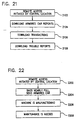
- Fig. 22 is a flow diagram depicting procedures for remote access initiated by the remote location;
and
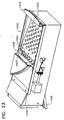
- Fig. 23 is a perspective view of the input tray, peak and initial portion of transfer tray,
according to an embodiment of the present invention.
-
DETAILED DESCRIPTION OF THE PREFERRED EMBODIMENT
-
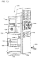
Figs. 12-18 depict a coin counter/sorter and coupon/voucher dispensing device according to one
embodiment of the invention. In the embodiment of Fig. 12, the device generally includes a coin
counting/sorting portion 1202 and a coupon dispensing portion 1204. In one embodiment, these
portions can operate independently in the sense that it is possible for the coin counting portion 1202 to
be counting one customer's coins while the dispensing portion 1204 is dispensing coupons and/or
vouchers to another customer. In the depicted embodiment, the coin counting portion 1202 includes an
input tray or hopper 1206, a voucher dispensing slot 1208, a coin red slot 1210, a sorting/counting
mechanism 1212, and customer I/O devices, including a keyboard 1214, additional keys 1215, a
speaker 1216 and a video screen 1218. The coupon dispensing portion includes an activating device
1220 such as a button and coupon receptacle 1222. The apparatus 1200 can include various indicia,
signs, displays, advertisement and the like on its external surfaces. In the depicted embodiment,
portions of the counting/sorting mechanism are visible through a window 1226. A power cord 1228
provides power to the mechanism as described below.
-
The depicted embodiment includes a number of interacting systems, as shown in Fig. 13,
including the coin holding/transfer system 1302, a waste control system 1304, the counting/sorting
system 1306, a control and I/O system 1308, and a voucher/coupon system 1310. In the depicted
embodiment, the coin-holding transfer system 1302 includes the pivoting tray or hopper 1206, a
transfer tray configured to form a peaked coin input system and a solenoid and gate system as depicted
in Fig. 15. The waste control system 1304, in one embodiment, includes perforated flow-through
surfaces of the hopper 1206, a slot and spout system in the transfer tray, a waste tray, a magnet system
and a fan or blowing system, as described more thoroughly below. The counting/sorting system
includes a coin hopper, a coin counter, coin sorter and coin collection bags, as depicted in Fig. 16. The
voucher/coupon system includes one or more dispensers and/or printers for dispensing and/or printing
vouchers or coupons in response to customer input, as depicted, for example, in Fig. 16. The control
and I/O system is provided for coordinating the operation of the waste control system, the coin
holding/transfer system, the counting/sorting system and the voucher/coupon system. Preferably, the
control and I/O system receives and provides appropriate information and instructions to and from the
user, and, in one embodiment, can be used for sending and receiving information to and from remote
sites such as for receiving operating information (such as discount information, coupon information,
updated software) and providing malfunction or diagnostic or statistical information.
-
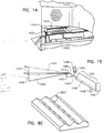
Fig. 7 depicts a pivoting tray system according to one embodiment of the present invention. In
this system, the tray 120, in the rest position 710, has a bottom surface with is substantially horizontal.
Coins can be fed into the transfer tray 230 by lifting the handle 715, causing the coin tray 120 to pivot
about point 730, so that the force of gravity can cause coins to move to the transfer tray 230.
-
In some cases, it has been found that the configuration depicted in Fig. 7 is less than optimal.
When the coins are placed on the horizontal surface, they reside in a pile or heap which is elevated
above the pivot point 730. Accordingly, as the coins are moved onto the transfer tray 230, they may,
depending on the volume of coins placed in the tray 120 travel into the transfer tray 230 in a surge of
coins. This surge can overwhelm and/or jam the downstream counting/sorting mechanism. This
problem is compounded by the fact that, if a large volume of coins is placed in the tray, once jamming
occurs, it may be of little avail to return the tray to its horizontal position since this will not serve to
move coins away from the transfer tray 230 and may even fail to stop the flow of coins into the transfer
tray 230. In the embodiment of Fig. 7, coins will commonly move into the transfer tray 230 in a flow
or mass of coins which is several coins deep such that some coins are lying on top of others as the
coins travel into the transfer tray 230. This configuration of coin flow interferes with effective
cleaning of the coins and contributes to jamming.
-
Fig. 14 depicts a coin tray or hopper according to another embodiment of the invention. In the
embodiment of Fig. 14, the bottom surface 1402 of the tray 1206, when the tray is in the rest or
lowermost position is angled downward in a direction away from the transfer tray. In this way, even
when the hopper 1402 is filled to the rim, the coins will not begin flowing into the transfer tray 1406
until the user begins lifting the tray, such as by lifting handles 1404. As the user lifts the hopper from
the lowermost position 1408 to an upper position 1410, coins heaped up to the upper rim 1412 will be
positioned higher than the pivot point or peak 1414. The first coins to reach a critical height above the
peak 1414 will begin sliding and will eventually move over the peak 1414 and into the transfer tray
1406. The peak 1414 has an angle such that in general, as the tray is lifted, coins will travel over the
peak 1414 in a single plane or layer, such that, in general, there will be substantially little or no overlap
of one coin over another. As described more thoroughly below, this type of coin flow provides a
number of advantages. It assists in the waste management system because it makes it possible to
expose each coin individually to a magnetic system and/or blowing system without one of the coins
blocking another coin from the waste management system. It also assists in preventing undesirable
surges or large flows of coins into the transfer tray 1406 since the flow of coins is limited by the fact
that, generally, only a single layer of coins travels over the peak 1414 at a given time. The system is
also useful because it is self-clearing in the sense that if a large coin flow is experienced, the user can
allow the tray to move downward towards its lowermost position 1418 which will cause coins to move
in a direction away from the tray 1406, thus clearing the entrance to the transfer tray 1406. Preferably,
the bottom of the tray 1402 is at an angle with respect to horizontal, between about 10° and about 15°,
preferably between about 11° and about 12° and is more preferably at an angle of about 11.56°. The
initial downward slope of the transfer tray is inclined with respect to horizontal, at an angle of between
about 25° and 35°, preferably between about 28° and about 31° and more preferably at an angle of
between about 30°. Thus, the angle 1422 between the bottom surface of the coin tray and the initial
slope of the transfer tray is between about 135° and 140°, preferably about 138°.
-
In one embodiment it has been found useful to provide a material to fill the crack 1424 around
the edge of the coin tray. Providing this material has been found useful in preventing coins from
falling into the crack and preventing pinching of user's fingers. In one embodiment, a stiff-looped
material such as that sold under the tradename Velcro™ (preferably, using only the loop material and
not the hook material) has been found useful, although other materials such as felt, rubber, plastic and
the like may be used.
-
As shown in Fig. 15, the transfer tray 1406 includes an initial sloped portion 1428 and a
downstream portion 1430. Preferably, the initial sloped portion 1428 as well as the bottom surface
1402 of the coin tray 1402, is provided with a number of perforations useful in the waste management
system as described more thoroughly below. A gate is positioned over the initial portion 1428 and is
movable from an upper open position 1432 to a lowered or closed position 1434. In one embodiment,
the gate movement is achieved by a controllable solenoid 1436, controlled by the control and I/O
system 1308, as described more thoroughly below. The open gate 1432 defines a slot through which
the coins, after passing over the peak 1414 must pass. This slot is closed by the gate when it moves to
the lower position 1434. Preferably, the gate remains in the lower position 1434 until the user initiates
the counting/sorting process (e.g., by pushing the start button) in order to prevent entry of foreign
material into the counting/sorting system during idle periods. In some embodiments, the gate is moved
to the closed position in response to a jam or other malfunction of the counting/sorting mechanism.
The site of the slot defined by the gate also assists in preventing undesirable flow or surge of coins by
preventing the passage of a flow of coins greater than a predetermined thickness such as greater than a
single layer or plane of coins.
-
The lower portion 1430 of the transfer tray has a lower surface 1406 having a plurality of
grooves running lengthwise, as depicted in Figs. 8A and 8B. This allows the coins to ride along the
peaks while liquids or other wastes flow or travel down the valleys 820. In the embodiment depicted
in Fig. 8B, a number of perforations are formed in the valleys of the transfer tray. In one embodiment,
the perforations have a substantially asymmetric "teardrop" shape with the narrowest region of the
perforation pointing towards the peak 1414, as depicted in Fig. 8C. This configuration is believed to
be particularly effective in removing waste material such as liquids. The waste material that passes
through the perforations 830' are funnelled to a spout 1438 which empties into a waste tray as
described below.
-
The perforations in the lower part of the transfer tray 1430 and the funnel and spout 1438 form
part of the waste control system 1304. The perforations in the upper portion of the transfer tray 1428
and the coin tray or hopper 1206 also are part of the waste control system 1304 since these perforations
allow dense waste material with a size smaller than the perforations to fall through the perforations and
thus to be separated from the coins. Materials falling through these perforations and the material
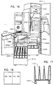
output from the spout 1438 are collected in a waste tray 1602, as seen in Fig. 16. Fig. 16 shows the
apparatus of Fig. 12 with the cabinet doors in an open position showing certain interior structures of
the apparatus. Waste tray 1602 is configured to lie beneath the perforated portions of the hopper 1206,
upper transfer tray 1428 and spout 1438 and to receive materials which pass through these devices.
The waste tray 1602 is configured to be drawn out in a drawer-like fashion for emptying waste
material. In one embodiment, the waste tray 1602 has a capacity at least equal to 12 fluid oz. so as to
be able to receive and contain, for example, the spilled contents of a typical soft drink can.
-
The perforations in the hopper 1206 and upper transfer tray 1428 also can provide a second
function in a waste control system. In this second function, a device is provided for blowing air
upward through the perforations so as to blow lightweight material off of the coins and away from the
counter/sorter. Preferably, one or more fans are provided for this purpose. The fans can be controlled
by the control I/O system 1308, e.g., to become activated upon pushing the activate or go button 1215.
Preferably, the air flow is configured to flow in a countercurrent fashion, i.e., to blow in a direction
from the clean region towards the dirty region, i.e., from the region of the counter/sorter towards the
transfer tray and coin tray. In one embodiment, two separate fans are provided. One fan provides flow
through the perforations in the bottom of the hopper and the upper portion of the transfer tray 1428,
1402. Another fan provides for air flow through the open gate 1432 and over the peak 1414. This
flow is useful in individually cleaning the coins as they pass, in a single layer, over the peak 1414
since, in this configuration, each coin will be individually subjected to the air flow. In one
embodiment, the second fan is configured in a box structure 1440 to provide more efficient air flow up
the transfer tray 1432 and over the peak 1414. The channeling of flow through the open gate 1432
and/or similar structure produces a convergence or "wind tunnel" effect so that a relatively high air
velocity is provided at the peak 1414 for efficient cleaning of the coins.
-
Coins which are output from the coin holding/transfer system 1302 are provided to the
counting/sorting system 1306. A coin hopper 1604 receives the coins from the transfer tray 1430 and
provides these coins to the counter-sorter mechanism. A number of counter-sorters can be used. In
one embodiment, Skycam Model 640 is used. Other sorter-counters include those sold by Brandt, Inc.
and Hitachi, Ltd. As depicted in Fig. 16, the hopper and sorter/counter are mounted on rails 1606a,
1606b so that they can be pulled outward for ease of cleaning, maintenance, replacement and the like.
In one embodiment, the hopper 1604 can be tilted upward for additional ease of cleaning and
maintenance.
-
The counter/sorter outputs the coins, according to various denominations of the coins into a
plurality of coin bags 1608 positioned in one or more rolling, removable trolleys 1610a, 1610b. In the
depicted embodiment, the coin bags 1608 are standard sized coin bags to facilitate disposition of the
coins, such as deposit with a bank. Preferably, the sorter is configured to place up to a predetermined
amount of coins of a given denomination into particular bags so that each bag, when filled by the
sorter, will contain a known amount of coins. Once one bag is filled with a given denomination, the
sorter can begin placing that denomination of coins into a second bag. Alternatively, the counter can
output coins to one of a plurality of bags designated for that denomination coin without keeping track
of how many coins have been placed in which bag. As shown in Fig. 17, the receptacles for the bags
are preferably tapered in shape 1702 so that, once the bags are filled with coins, they can be easily
removed from receptacles without jamming. Castes 1704 facilitate withdrawal from the apparatus
1200 e.g., for removal of full coin bags, and transfer to a desired location. Although Fig. 16 shows
trolleys 1610b configured to accomodate 5 and 3 bays, respectively, other configurations can be used.
In one embodiment, each trolley is configured to accomodate two rows of bags, a front row and a rear
row, with eight bags in each row.
-
In one embodiment, the apparatus provides for restricted access to the counted coins, i.e., the
coin bags, such as by a mechanical and/or electronic lock which restricts access. In one embodiment,
the coin bags will normally be accessed only by authorized money transfer agencies, such as a armored
car service and would not normally be accessible by, for example, store personnel. Preferably, store
personnel are able to access the interior of the device such as by opening doors, as depicted in Fig. 16,
without normally having access to the locked coin bags. In one embodiment, the apparatus detects and
stores in memory any access to the coin bags, such as by unlocking the coin bag locks. Preferably, the
apparatus will store such information as the time of access, the mode of access and/or the identity code
of the person accessing the coin bags. In one embodiment, the apparatus will also record in memory
information regarding other types of access to the machine, such as any access by store personnel to
the interior of the device, even though it may not include access to the coin bags.
-
Operation of the counting/sorting system 1306 is controlled by the control I/O system 1308. In
one embodiment, the counting and sorting system is activated in response to the user pushing the
activate or "go" button 1215. The counting/sorting system 1306 also provides information back to the
control and I/O system 1308. The control and I/O system receives information regarding the results of
the counting process, in particular, information relating to the number of coins and/or value of coins
which have been counted. Preferably, this information is displayed on the screen 1218, along with
instructions, advertising, attraction displays and the like. Preferably, the counting/sorting system also
provides information to the control and I/O system 1308 regarding its status, such as a detected jam or
other malfunction or the empty state of the hopper or counter/sorter.
-
In one embodiment, the microprocessor can respond to a detected jam in such as way to, in many
cases, clear the jam automatically (i.e., without requiring intervention by, e.g., store personnel). In one
embodiment, the apparatus temporarily suspends flow of coins into the counter, e.g., so as to
accumulate a number of coins in the hopper 280. After coins are accumulated in the hopper, the
microprocessor suddenly permits the accumulated coins to enter the counter so as to, in many cases,
use the sudden flow of coins for a means for dislodging a jam. In this way, it is possible to use the
microprocessor-controlled flow of coins to achieve clearing of at least some types of counter jams
without having to perform any substantial modification on the coin counter, e.g., by using software.
-
The control and I/O system, after a predetermined period has elapsed, following an empty state
signal from the counting/sorting system, can output a signal to the voucher/coupon system 1310 to
issue a voucher, optionally after verifying with the user (e.g., via the keyboard) that all desired coins
have been input into the system. The voucher/coupon system 1310 then outputs a voucher related to
the value of the coins counted by the counting/sorting system. In one embodiment, the voucher has a
value equal to the value of the counted coins. In another embodiment, as an inducement for using the
counting/sorting system, the voucher may be for an amount greater than the counted amount. In one
embodiment, the excess amount may be usable only at the retail location where the apparatus 1200 is
installed. In another embodiment, as a means of deriving income from the counter/sorter system, the
voucher may be for an amount less than the counted amount such as by deduction of a fixed service fee
or a percentage service charge.
-
In the depicted embodiment, the voucher is output by a printing system. Preferably, the printing
system is a non-impact printing system so as to reduce the amount of noise generated by the system.
The non-impact system can be a thermal printing system, laser printing system, inkjet system or the
like. If the noise can be tolerated, an impact system can also be used.
-
The voucher is redeemable, preferably, at the retail location where the apparatus 1200 is
installed. In one embodiment, the voucher is redeemable only for merchandise purchased at the retail
location where the apparatus 1200 is installed. In another embodiment, the voucher can be redeemed
either for merchandise or for the cash value of the voucher. In still another embodiment, the value of
the sorted coins can be transferred to one or more accounts held by the customer, such as by an
electronic transfer of the amount to these customer's bank account. In one embodiment, the apparatus
1200 includes a magnetic card reader, e.g., for reading a magnetically-encoded bank card to facilitate
transfer of the funds to the user's bank account.
-
Preferably, the apparatus 1200 also has the capability for outputting coupons or other marketing
or advertising material. In one embodiment, coupons are output whenever a voucher is output, both to
provide an inducement for using the sorter/counter and to encourage the user to employ the voucher
for purchasing goods, rather than obtaining cash equivalent.
-
Although, preferably, the vouchers are printed within the apparatus 1200, it is also possible to
dispense pre-printed vouchers and/or coupons. Preferably, the vouchers and/or coupons include
security devices to guard against counterfeiting.
-
In one embodiment, the voucher dispensing system can be run independently of the coupon
dispensing system. This can be achieved, for example, by having independent voucher printers and
coupon disperses, each controlled in response to the control and I/O system. Preferably, coupons are
dispensed to a user whenever the user uses the device 1200 for counting coins and receiving a voucher.
Preferably, the coupon dispensing system can be used independently from and simultaneously with the
counting/sorting and voucher dispensing system. For example, the device can be configured such that
while a first customer is waiting for the device to finish counting and sorting coins, a second user can
request and receive coupons from the machine. In one embodiment, coupons are dispensed in
response to the user inserting a coin in a coin slot. Preferably, the device is configured such that any
coin inserted in the coin slot is immediately returned to the user, along with at least one coupon. Thus,
the coin slot used in conjunction with the coupon dispenser is a means for informing the apparatus
1200 that a user wishes to receive coupons. Other items for requesting coupons (or providing other
user I/O) could be used such as a push button, keyboard, handwritten input or handwriting recognition,
voice recognition and the like.
-
In one embodiment, vouchers and/or coupons include printed information relating to items
available for sale in the store in which the apparatus 1200 is installed. In one embodiment, the
apparatus 1200 can be programmed and, as needed, updated to include information specific to the
particular store location. For example, the voucher and/or coupon can be printed including a
"shopping list" format which includes information regarding the location, in this particular store, of
items for sale. For example, the coupons can be printed including information about which aisles the
products for which the coupons apply are located in.
-
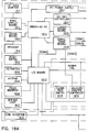
Fig. 18 is a block diagram depicting some of the major components of the control I/O system
1808, the counting/sorting system 1806 and the voucher/coupon system 1810. The central component
of the control and I/O system 1808 is a data processing system, preferably, a PC-type system such as
386DX-40 PC system, such as that available from Atronics, as Model ATI-386VL 1812. The data
processing system 1812 provides output to a monitor such as a 14 inch SVGA monitor 1814 via an
SVGA display board 1816. Audio output can be provided to a speaker 1818 via a sound board 1820
using any of the sound boards available in the art. Mass data storage is provided by a hard disk drive
1822 controlled through a hard disk drive controller 1824. A modem board 1826 is used for providing
communication via a modem connected to a telephone line 1828 when desired. Modem
communication can be used for uploading or downloading data and/or programs to the data processor
1812. For example, changes in types or values of coupons to be dispensed can be downloaded from a
central location. Information regarding the location of products within the store (e.g., for outputting a
"shopping list" format coupon or voucher, as described above) can be provided via the modem 1824,
1826.
-
Communication can also be provided through one or more non-modem communication lines
such as the depicted serial communication lines 1832, 1834. In the depicted embodiment, one of the
serial communication lines 1834 is connected to the coin counter/sorter 1836 or "scan coin" assembly.
This communication line 1834 can be used, for example, to communicate to the data processor 1812
the numbers or value of coins which have been counted or to communicate commands from the data
processor 1812 to the sorter/counter 1836 such as commands to commence operation.
-
Serial communication line 1832 can be used for a number of purposes, such as for providing for
service communications. In one embodiment, a serial I/O port is provided to enable connection of the
data processor 1812 to another computer such as a laptop or other portable computer. In this way,
service personnel can communicate directly with the central data processor 1812, such as for purposes
of performing maintenance or diagnostic services, uploading new data or programming, downloading
data such as statistical information and the like. In the depicted embodiment, the serial lines 1832,
1834 are controlled through a serial communication board 1838 of a type known in the art. In the
depicted embodiment, the serial communication board 1838 also communicates with an input/output
(I/O) board 1842. The I/O board 1842 is configured to receive and transmit communications from and
to the user or other personnel. In this regard, the I/O board is connected with a key pad, such as a
standard 12-key numeric keypad 1844 and one or more key switches 1846, such as key switches for
"Go," "Cancel," and the like. In the depicted embodiment, the I/O board 1842 can provide audio
output, e.g., via a piezo beeper 1848 and/or an activatable light, such as a light for informing store
personnel that service is needed. A reset switch 1852 is provided for issuing a hard reset command to
both the data processor 1812 and the I/O board 1842. A PC power supply 1854 receives power torn
an external power supply such as 630 watt, uninterruptable power supply 1856 and provides
conditioned power to the processor 1812 and hard disk drive 1822.
-
The power supply 1556 preferably provides a source of power directly to the I/O board 1842.
Preferably, the data processor 1812 and/or I/O board 1842 include non-volatile memory sufficient to
permit orderly shutdown of the system in the event of a power failure without loss of vital data or
programs. Preferably, the uninterruptable power supply 1556 provides sufficient power to permit
orderly shut down and termination of processing in the event of failure of the power source such as
interruption of power through the power cord extension 1858. The power supply 1856 also preferably
provides power directly to the monitor 1814, counter/sorter 1846, and, via 24 volt and 5 volt power
supplies 1862, 1864, to the I/O board 1842.
-
The I/O board 1842 is used to control portions of the waste control system, such as the dirt
removal fan 1866, portions of the counter/sorter mechanism such as a vibrating coin feeder 1868 and a
coin accepter or hopper 1872. In the depicted embodiment, the I/O board 1842 controls the coupon
dispenser 1872 and, via a voucher printer controller 1874, a voucher paper feed 1878, and a voucher
printer/cutter sub-assembly 1882.
-
Fig. 16 depicts the location of a number of components in the system according to one
embodiment. Preferably, when the doors 1622, 1624 are in the open position as shown, most or all of
the components are accessible for cleaning and/or maintenance. In the depicted embodiment, the
voucher printer 1882 is mounted on the inside of the door 1622. A number of printers can be used for
this purpose. In one embodiment, a model LPT 5242-448 printer, available from Seiko is used. The
right-hand portion of the cabinet includes the coupon feeder 1874 for dispensing, e.g., pre-printed
manufacturer coupon sheets through a chute 1626 to the coupon hopper 1222 on the outside portion of
the door 1624. The computer 1626, in the depicted embodiment, is positioned at the top of the right
hand portion of the cabinet in order to provide a relatively clean, location for the computer. The I/O
board is positioned adjacent the sheet feeder 1632.
-
In operation, the user who wishes only to receive a coupon will indicate such by an input device
which can be, e.g., a button, to be pushed by the user. In one embodiment, the user can activate the
coupon feeder by inserting a coin into the dummy coin slot 1220 which will be returned via coin return
slot 1221. The button or other input device transmits a signal to the processor 1812 indicating that the
user has expressed a wish for coupons. In response, the data processor 1812 sends a signal to the
coupon dispensing unit 1874 to dispense a predetermined number of sheets of coupons (such as a
single sheet) into the hopper 1222. In one embodiment, the microprocessor will stop or delay the
dispensing of coupons if more than a predetermined number of requests for coupons have been input
during a short period of time. This is to prevent, for example, mischievous depletion of the coupons.
In one example, if the microprocessor detects three coupons requests within a predetermined period of
time, such as ten second the microprocessor will suspend any dispensing of coupons for a period of
time, such as thirty seconds.
-
Although in the depicted embodiment, the input device for requesting coupons is relatively
simply (such as a single request button), it is also possible to provide a more sophisticated interface,
such as allowing the user to request specific desired coupons from a menu.
-
A user who wishes to employ the coin counter/sorter will initially place coins to be sorted into
the coin tray 1206. In response to instructions displayed on the screen 1218, the user will then push the
start or "Go" button 1215. Preferably, some or all of the buttons activated by the user are "soft"
buttons, i.e., in which the location, indicator, legend or other meaning of the activation button is
indicated on a changeable video display (such as, for example, an arrow on the display pointing to the
button which the user should push to activate the device). Upon receiving an indication that the "Start"
button 1212 has been activated, the data processor 1812 outputs a plurality of commands to initiate the
counting/sorting operation (some of which are output via the I/O board 1842, as shown in Fig. 18).
The commands can include commands to activate the components of the waste control system such as
the fan 1866, magnet, etc., to open the gate by activating the solenoid 1436, and/or to activate the
vibrating coin feeder 1868. The computer 1812 may also output actions to the user, such as
instructions to lift the handle of the coin tray to initiate the flow of coins. A number of user interfaces
can be provided. In one embodiment, the apparatus can receive input indicating whether the user is a
novice user or an experienced user of the device. In this way, detailed instructions can be provided to
the novice while the experienced user can be provided with a more rapid series of instruction displays.
In either case, it is preferred to provide a device which will achieve the desired coin counting with a
relatively low total number of button pushes. Preferably, the user need only push a first button to start
the counting procedure and a second button to stop the counting procedure. Other interfaces could be
used which will automatically detect the insertion of coins into the tray (so as to eliminate the start
button requirement) and or detect the cessation of flow of coins and/or the empty state of the input
hopper or tray, so as to eliminate the need for a stop button push.
-
As the user lifts the tray, coins will pass, with a limited depth, preferably in a single layer, over
the peak 1414 and into the transfer tray 1428, 1430. While passing over the peak, they will be cleaned
by a blowing mechanism as described above. Passing down the transfer tray they will pass by the
magnet, as described above, to separate for example, magnetic bus tokens and the like from coins.
Foreign material and liquids will either be blown off the coins and out of the machine or will fall
through the perforations and into the dirt tray. The coins passing down the transfer tray will pass into
the coin hopper 1634 for movement, by a vibrating coin feeder connected to the output of the hopper,
to the counter/sorter mechanism 1212. The counter/sorter mechanism counts the coins and a running
total is stored in memory, either in the counter/sorter mechanism 1212 or the control I/O mechanism
1308. Preferably, the computer 1812 presents a running total of the value of the coins on the screen
1218 during the counting process. After being counted, they are sorted according to denomination and
placed in coin bags 1608, also according to denominations. The counting/sorting mechanism 1306
informs the computer 1812 when coins are no longer input into the mechanism. After a predetermined
amount of time has passed following cessation of coin flow, such as about 10 seconds, the computer
1812 will cause the screen 1218 to display a message to the user asking whether the user has input all
desired coins. Once the user has verified that all desired coins have been input, the computer 1812
controls the voucher/coupon system 1310 to output a voucher in an amount related to the value of the
coins which were counted, preferably an amount at least equal to the value of the coins that have been
counted. In one embodiment, the computer 1812 also causes one or more coupons to be dispensed
1874 so that the user can receive both a voucher in the value related to the value of the coins and one
or more coupons.
-
Fig. 19 depicts the procedure for counting coins which also includes recording certain pertinent
information. Preferably, the information is recorded by the computer on non-volatile media so that the
information is not lost upon a power loss or a power-down. As described above, after a "begin" or
"go" signal is received 1902 the device initiates the counting 1904 until such point as the stop signal is
received 1906, generally as described above. After the coins have been received and counted, the
voucher amount is calculated 1908. In one embodiment, the voucher amount is related to the total
counted amount by being equal to the total amount less a transaction fee. In one embodiment, the
transaction fee depends upon the numbers of various dominations, for example, the fee might by ten
cents for each dollar of pennies counted and five cents for each dollar of other dominations counted.
In another embodiment, the voucher amount is related to the total amount by being equal of the total
amount. In still another embodiment, the voucher amount is related to the total amount by exceeding
the total amount, e.g., to provide a premium for using the counting device.
-
After the voucher amount is calculated the voucher is printed 1910. Preferably, the voucher
includes a number of items of information in addition to the amount of the voucher. These additional
items of information can include one or more of the location or other identifier of the machine at which
the counting was done, the location or other identifier of the store or other place where the voucher
may be exchanged for cash or merchandise, the time and date of the transaction, the total amount
counted, the number coins of each denomination counted, the number of rejected coins or other items,
and a transaction control number. Preferably, the control number is unique, at least to the particular
location and date or time. In one embodiment, the voucher is printed with a scannable code such as a
bar code. This permits easy exchange of the voucher, e.g., by scanning the bar code e.g., at a grocery
or other retail check out stand in the same way universal product code (UPC) bars codes are scanned.
-
The apparatus records, preferably using a computer and recording onto a non-volatile media,
information regarding the transaction. In one embodiment, the information which is recorded includes
the information noted above that can be included on the voucher, such as the voucher amount, a
control number, numbers of coins counted and time of transaction 1920.
-
Preferably, the apparatus also determines the amount that has been deposited in the various coin
bags. This permits the apparatus to output a signal or notification when the bag capacity is nearly full,
to enable armored car personnel or other personnel to retrieve the full bags and replace those with
empty bags 1922 as described more fully below. As noted above, the apparatus, in one embodiment,
will also automatically dispense one or more coupons 1924 at the conclusion of a counting transaction.
-
The printing of various information on the voucher 1910 and the recording of various
information about the transaction 1920 serve a number of useful functions. Providing information on
the voucher gives the user an extra opportunity to verify accuracy and/or acceptability of the count
and, potentially, detect any malfunctions that may have occurred. The information is also useful to
store personnel in verifying accuracy and authenticity of the voucher. Store personnel may be able to
detect an inaccurate or unauthentic voucher if, for example, the voucher indicates a transaction time
during which the store was not open, or indicates similar inconsistencies. Furthermore, store personnel
can, if suspicious, check the information printed on the voucher against the information recorded in the
device (as described more fully below) to further check authenticity.
-
The recording of information 1920 is useful for a number of reasons. First, the information is
useful in facilitating the removal of coin bags for deposit, e.g., in a bank, as described more fully
below. The information is useful to store personnel in verifying particular transactions or detecting
malfunctions. The information is useful to the counting machine operating company to verify amounts
counted and amounts deposited in the bank and to help determine the source of errors if there is a
discrepancy between amounts removed from machine and amounts deposited in the bank. For
example, the recorded information is useful to both the operating company and the store personnel to
diagnose malfunctions or to become aware of servicing or maintenance needs of the apparatus.
-
Fig. 20 depicts a procedure for permitting, facilitating and recording information relating to
access of the machine, i.e., access to features or components of the machine other than those for
normal counting, voucher and coupon dispensing, used by an ordinary user. The depicted embodiment
records information relating to armored car (or other monetary transfer services) access and store (or
other remote location facilities) access. Other types of access could include service, repair or
maintenance access, such as by an independent service or maintenance contractor and/or access by the
counter apparatus operating company.
-
In the depicted embodiment, the machine can detect an access, or attempted access and will
record the time of this event 2002. In one embodiment, the apparatus includes a key switch which, by
inserting and turning the key, can change the machine from a run mode to a store access mode and/or
an armored car access mode. Preferably, the keyswitch is configured to provide a signal to the
microprocessor upon changing the mode to permit the apparatus to detect the access or attempted
access and to record the time of the event.
-
After the attempted access is detected (such as by the turning of a keyswitch) the apparatus is
preferably configured to receive an authenticating input such as a personnel identification number
(PIN), preferably in response to a prompt output by the device, and the identification is then recorded
2004. The procedure followed thereafter depends upon whether the access is by store personnel or
armored car personnel 2006.
-
In one embodiment, the types of access and information available to store personnel are limited.
For example, the store personnel may be permitted to review information relating to the various
transactions that have occurred in the counting device 2008. The device may display the most recent
transaction and may print receipt of a command (e.g., through a key board) to scroll to previous or later
transactions. In some embodiments, the store personnel now may be permitted to review status
information (e.g., total amounts counted, amounts removed by armored car carriers, amount of
coupons in the device, full/empty state of coin bags, etc.) or may be permitted to review problem
reports (jams, paper or coupon misfeeds, power outages and the like 2010).
-
In one embodiment, the device can output (either in run mode or in store access mode)
instructions regarding how to repair minor problems or service or maintain the device, such as
instructions clearing a jam replenishing the supply of coupons, paper, ink and the like 2012.
-
After the store personnel has finished the store access procedures desired, the store personnel will
return the machine to "run" mode and the machine will detect and record the end of access by store
personnel 2014.
-
In cases in which the accesses is by an armored car personnel, typically for the purpose of
retrieving coin bags, e.g., for deposit in a bank, several items will be printed by the machine.
Preferably, the printing will be performed by the same printer used for printing vouchers, and will be
under the control of the microprocessor. One item which may be printed is a receipt for the armored
car personnel which memorializes the amount of money which the armored car personnel is retrieving
from the device 2020. Preferably, the receipt will be also imprinted with a control number.
-
Preferably, the machine will also print bank deposit slips for use when the retrieved money is
deposited into the bank 2022. In one embodiment, the money will be deposited in two or more
accounts. For example, in one embodiment the transaction fee (described above in connection with
Fig. 19) is deposited into the account of the owner/operator of the counting machine while the
remaining funds are deposited into the account of the retail store or other location where the voucher is
exchanged. Other embodiments may also be possible. For example, in one embodiment the counting
apparatus owner/operator may charge a service fee to the store or retail outlet over and above any
transaction fee which will thus affect the amounts of the respective deposit slips. Alternatively, the
counting apparatus owner operator may wish to receive an amount which is less than the transaction
fee (if any) charged to the user, thus effectively splitting the transaction fee between the counting
apparatus owner/operator and the store. In another embodiment, it may be that there is no transaction
fee obtained from the user and, instead, the machine owner/operator may charge a fee directly to the
store. These and other variations and alternatives can be reflected in the amounts calculated for the
various deposit slips 2022. Preferably, the deposit slips will also be imprinted with a control number
for later verification.
-
In one embodiment the apparatus will also print tags 2024 to be attached to the various coin bags
that are being removed. The tags will preferably indicate the denomination of coins in each bag and
the number of coins of that denomination. Preferably, the coin bag tags will also be imprinted with a
control number. In one embodiment, the same control number is used for all of the printed items 2020,
2022, 2024. The printed items 2020, 2022, 2024 may also contain other information such as store
location, machine identifier number, time and date and the like.
-
Preferably, the apparatus will record pertinent information, such as by using the computer to
record information on non-volatile media. The information recorded can include one or more of the
beginning balance, the number and types of coin bags removed, the denomination and number of coins
in each bag removed, the amounts of the respective deposits, the control number or numbers and the
ending balance 2026.
-
In one embodiment, armored car personnel are also used to provided service and/or maintenance
to the machine. In one embodiment, the machine can provide requests or instructions for providing
such service, such as by requesting or instructing the armored car personnel to load additional or new
coupons, to replenish the supply of paper, ink and the like 2028. After the armored car personnel have
finished their tasks, they will close the machine and return the machine to run mode. At this point, the
machine will detect that the armored car access has ended and will record the ending time of the
armored car access 2030.
-
In addition to accessing information by obtaining it directly at the site of the counting machine,
the apparatus is also configured for providing information from the field location of the machine (or
"remote location") to, for example, a central location such as offices of the owner/operator of the
machine. Remote access can also be performed in connection with other entities such as a bank or an
accounting firm. In one embodiment, the communication can be performed using a communication
device such as modem board 1826. Communication can also be performed over a local area network
system, over a wireless communication system (such as a wireless LAN or a cellular telephone
communication system, or by a cable communication such as an interactive television or video
communication system.
-
Fig. 21 depicts a procedure in which remote access is initiated by the central location 2102. For
example, the central location may initiate access to one or more of the various remote sites in order to
obtain information, e.g.. as needed for accounting, maintenance and the like. In the embodiment of
Fig. 21, the central location can instruct the remote site to download information relating to armored
car transactions 2104, typically comprising the information that was recorded in connection with an
armored car access, as described above in connection with Fig. 20. The central location can instruct
the remote location to download information regarding the various transactions that have occurred,
e.g., over a predetermined period of time 2106. The transaction information can include, for example,
the information recorded in connection with transactions, as described above in connection with Fig.
19. The central location can instruct the remote location to download information relating to service or
maintenance status or problems 2108. For example, the downloaded service or trouble reports can
include information about the times and nature of various malfunctions such as, jamming, misfeeds
and the like. The downloaded information can include information about the status of items which
may need attention such as loading of additional or new coupons, loading of tape, ink and the like, or
notification of required periodic maintenance such as cleaning, battery or other component replacement
and the like.
-
Fig. 22 depicts a remote access that may be initiated by the remote location 2202. For example,
the remote location may initiate a call to the central location in a situation in which the coin bags are
nearly full, thus informing the central location that it is necessary to dispatch an armored car to service
the remote location 2204. The remote location may initiate a call in order to inform the central
location of a malfunction 2206. Preferably, several levels of malfunction can be detected by the
device. As noted above, in some embodiments, the machine may be capable of clearing some types of
coin jams without intervention of either store personnel or central location (service) personnel. In
some cases, the machine may detect a malfunction which is not of the type which can be automatically
cleared or may have attempted to automatically clear a malfunction, without success. In this case, the
machine may, in some instances, attempt to notify store personnel of the situation and/or may attempt
to notify store personnel of procedures to be followed in order to correct the situation. Such a
notification could include sending a signal to the store central computer, illuminating a "trouble" light
or other indicator, displaying a message on the video screen, or the like.
-
In some cases the machine may experience a malfunction which it determines can not be or was
not cleared automatically and which can not be or was not corrected by store personnel. In this case,
the device may initiate access to the central location to report such a malfunction, thus permitting the
central location to dispatch service personnel to correct the situation.
-
The remote device may initiate a call to the central location in order to inform the central location
that maintenance needs to be performed, such as loading additional or new coupons, loading papertape,
ink and the like 2208.
-
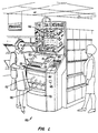
Figs. 1-11 depict a second embodiment of a coin exchange kiosk 100 in a possible environment;
a supermarket. The embodiment of Figs. 1-11 shares many features with the embodiment of Figs. 12-18
and descriptions of such common features below apply to corresponding features of the
embodiments of Figs. 12-18. In Fig. 1, kiosk 100 is free-standing, and has been designed with a small
footprint to reduce or minimize the required floor space. The lower front surface 110 is clear, allowing
the user to watch the coins as they are separated, counted, and dropped into escrow tray 105. By
making the process visible to the user, trust in the machine is encouraged. Furthermore, since
watching the sorting process is interesting, the user becomes integrated into the machine's operation
and is further encouraged to use the machine.
-
Initially the coins are placed in coin tray 120 where small foreign objects fall through
perforations in the bottom of the tray and the user can remove large foreign materials prior to coin
sorting. When the user is ready to begin the sorting process, they must push "go" button 115. Button
115 initializes the coin counter, activates the coin sorter, and activates the fan within the waste
management chute. If the system does not detect coins within a predetermined period of time, both the
coin sorter and the fan are deactivated. The user next raises the edge of tray 120. The tray is hinged
on the right side and acts as a chute to funnel the coins into the kiosk. User directions, transaction
information, store bargains, and advertisements appear on video screen 130. Screen 130 can also be
used to show attention getting displays in order to attract potential users. Once the coins are admitted
into the kiosk and the go button has been pushed, the waste removal and coin sorting process begins.
During the coin sorting process, coins which do not meet predetermined physical criteria are rejected
and returned to the user via chute 165. In one embodiment, as the coins are counted the video screen
displays both the total monetary value and the number of coins collected within each denomination.
-
At the conclusion of the sorting process, the user is asked to either accept the stated coin value
and continue the transaction, or cancel the transaction. This selection is made by pushing one of two
buttons 150. If the user continues the transaction, then the coins in the escrow tray 105 are dumped
into a depository and the user is issued a voucher through slot 160. In one embodiment, the voucher is
worth the value of the counted coins and is redeemable at the retailer's cashier for cash or credit
towards purchases. Store coupons, printed by the voucher printer and good towards store bargains, are
dispensed with the cash voucher. Manufacturers' coupons are dispensed through an adjoining slot 165
at no cost to the user. If the user cancels the transaction the coins are returned in area 170. The upper
back portion 140 of kiosk 100 is a display board where advertisements and notices can be placed.
Display board 140 can also be used to indicate what coupons the machine is currently dispensing.
-
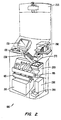
The internal layout of kiosk 100 is shown in Fig. 2. The coin storage area 210 holds the coins
after the transaction has been completed. Area 210 can either be separated into large capacity bins to
hold each denomination, or into ready to use coin trays. When the storage area is close to capacity, an
indicator 255 on the outside of the kiosk 100 notifies store personnel to empty the storage area 210.
-
The outside of the waste management system 230 is visible in this diagram. Liquids fall through
the porous, grooved bottom plate of system 230 while lint and other fine materials are blown away by a
small fan located in the chute. Liquids are collected in a waste receptacle. At the end of system 230,
the coins are funneled into the coin counter and sorter 280. This is a commercially available sorter.
Several manufacturers make suitable machines, although in one embodiment a Scan Coin Model 109
with a modified hopper is used. The counter accepts mixed coins and is able to detect foreign coins
and slugs. Rejected coins are returned to the user through chute 165.
-
In one embodiment of the kiosk, two different printers are used. Printer 270 is used to print the
cash vouchers and the store coupons. Printer 270 can be, e.g., an Epson TM267 printer. Besides
containing the amount of the voucher, the voucher will also contain other information such as store
name, transaction number, bar codes, etc in order to make counterfeiting difficult. Special papers and
inks can also be used to discourage counterfeiting. In one embodiment, a separate printer 295 makes a
continuous record of each transaction. This printer is an Epson RP265. In a second embodiment
printer 270 serves a double function. Besides printing the vouchers, upon command by store personnel
this printer prints out all of the pertinent transactional information. CPU 290 also stores this
information.
-
In one embodiment, VGA screen 250 is a Super VGA monitor; CPU 290 is a Belmont, 386,
40MHz CPU; and high capacity sheet feeder 260 is a modified 1000 sheet feeder manufactured by
Gradco, model number HCF-1000. Warning light 255 warns store personnel when either printer is low
on paper, the sheet feeder is low on paper, or there has been a system malfunction.
-
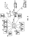
Fig. 3 is a block diagram of the system level electronic functions. The entire system is controlled
by CPU 290. System information is presented on display 130 which is the same monitor used to
communicate with the user. System inputs are coupled to CPU 290 via data bus 380. Push button
switches 330 and 325 are used by the user to either accept or cancel the transaction. Switch 335 is a
maintenance switch which is used by store personnel to command the system to download system
information to either the maintenance printer 295 or to a floppy disk. The maintenance switch may
also be used to enter a mode to allow clearing of coin jams and an internal store coin counting mode.
This internal store coin counting mode will enable the retailer to sort and count coins from vending
machines and cash registers, bypassing the voucher and coupon functions. Leading edge sensor 340
tells the system each time a sheet of coupons has been dispensed. Stepping motor 320 dispenses the
coupon sheets. Push button switch 115 is depressed by the user to initialize the counting system and
activate both the coin counter/sorter 280 and the waste management fan. Microswitches 350 and 355
deactivate escrow tray stepping motor 360, thus preventing possible mechanical damage by the
stepping motor moving the tray past its designated limits, and indicate to CPU 290 the position of the
escrow tray (i.e., at-rest position, returning coins to the user position, or dumping coins into the
machine's storage area position). CPU 290 also controls the voucher printer 270.
-
The flow chart of Fig. 4 illustrates the operation of the coin exchange kiosk according to one
embodiment of the invention. The user places coins of varying denominations into the external tray
(step 405). Small foreign matter falls through perforations in the bottom of the hopper tray (step 410)
while large foreign matter is removed by the user (step 415). When the user is ready to begin using the
machine, they press the "go" button (step 420). Pressing the go button activates the coin sorter,
initializes the coin counter, and activates the fan within the waste management chute (step 425). Next
the user lifts the edge of the hopper tray, dumping the coins down the entrance chute of the waste
management system (step 428). As the coins go through the waste management system certain waste,
such as liquids, are removed (step 430). The coins are then counted and sorted (step 440). During this
step coins which do not meet predetermined physical criteria are rejected and returned to the user (step
435). As the coins are counted, the value of the coins is displayed on the monitor as well as the
number of coins counted within each denomination (step 440). Manufacturers' coupons are dispensed
at this time (step 440). After all of the coins are counted, the user is asked to either accept the value
that has been determined and continue the transaction or to reject the value and discontinue the
transaction (step 450). If the user decides to reject the stated value then the coins are returned (step
455). If the user decides to accept the stated value and continue the transaction then a cash voucher is
dispensed for the stated value (step 460).
-
The flow chart of Fig. 5 illustrates the operation of the coin exchange kiosk in a second
embodiment. The user places coins of varying denominations into the external tray (step 505). Small
foreign matter falls through perforations in the bottom of the hopper tray (step 510) while large foreign
matter is removed by the user (step 515). When the user is ready to begin using the machine, they
press the "go" button (step 520). Pressing the go button activates the coin sorter, initializes the coin
counter, and activates the fan within the waste management chute (step 525). Next the user lifts the
edge of the hopper tray, dumping the coins down the entrance chute of the waste management system
(step 528). As the coins go through the waste management system certain waste, such as liquids, are
removed (step 530). The coins are then counted and sorted (step 540). During this step coins which
do not meet the predetermined physical criteria are rejected and returned to the user (step 535). As the
coins are counted, the value of the coins is displayed on the monitor as well as the number of coins
counted within each denomination (step 540). Manufacturers' coupons are dispensed at this time (step
540). After all of the coins are counted, the user is asked to either accept the value that has been
determined and continue the transaction or to reject the value and discontinue the transaction (step
545). If the user decides to reject the stated value then the coins are returned (step 550) and the
transaction ends (step 595).
-
If the user decides to accept the stated value and continue the transaction then they are asked
whether they would like to donate, in whole or in part, the value of the coins to a charity (step 553). If
the user does not wish to donate to a charity then a cash voucher is issued (step 577) and the
transaction ends (step 595). If the user wishes to donate to a charity, then the user is asked to chose to
which charity they wish to donate ( steps 557, 560, 565, and 570). If they do not wish to donate to any
of the listed charities, then the transaction ends (step 595) and the coins are returned (step 573).
-
After choosing to which charity they wish to donate, the user is asked if they wish to donate the
total value of the coins (step 580). If the user wishes to donate the total amount then a receipt is issued
which states the amount and the charity (step 583). CPU 290 records the amount donated and the
charity (step 583) so that when the coins are removed from kiosk 100 the proper amounts can be
deposited to the appropriate charity organizations. If the user selects to donate only a portion of the
total amount, they then enter the amount to be donated (step 587). At this point a receipt for the
donated portion is issued, a cash voucher for the remainder of the total amount is issued, and CPU 290
records the amount donated and the charity for later disbursement of funds (step 590).
-
Fig. 6 is a block diagram of the stepping motor control circuitry for the two stepping motors used
in kiosk 100. One stepping motor controls the coupon dispenser and the other stepping motor controls
the escrow tray. The circuitry for the two motors are duplicates of one another. The oscillators in
blocks 615 and 620 generate the pulses which set the stepping motor rates. The dip switches in blocks
615 and 620 allow manual setting of the oscillator rates. Each motor has a second oscillator, blocks
625 and 630, which set the chopping rate. The step pattern translators, blocks 635 and 640, use both
oscillators to generate the step motor patterns. Two different oscillators are used in order to maximize
the power efficiency.
-
In operation, computer 290 determines when power should be supplied to either the coupon
dispenser stepping motor 645 or the escrow tray stepping motor 650. This input is supplied via
interface 610. This signal is received by either input selector 655 or 660. In one embodiment, this
signal is digital. Depending upon the signal, the selector determines the length of time the stepping
motor will be operated. For example, one signal from interface 610 will cause the coupon dispenser
(motor 645) to dispense only a single sheet of coupons while a different signal will cause two sheets of
coupons to be dispense Similarly, one signal from interface 610 will cause the escrow tray (motor
650) to rotate in one direction thereby returning coins to the user, while a different signal will cause the
opposite motor rotation thereby depositing the coins into the coin receptacle. The power drive units
665 and 670 supply, upon command, sufficient power to operate stepping motors 615 and 650.
-
Fig. 7 is a side view of coin tray 120 and waste management chute 230. Coin may 120 normally
is flush with the top surface of kiosk 100 (Position 710). The user places their coins in the tray and at
this point removes any obvious foreign materials. When the user is ready to begin the sorting process,
they lift handle 715 on coin tray 120. The tray is hinged at point 730. When tray 120 is in position
720, the coins fall through waste management chute 230. The coins leave chute 230 through opening
740 to enter the coin sorting and counting mechanism. Liquids accidently dropped into the coin
hopper are funneled through spout 750 to a suitable collection receptacle.
-
Fig. 8A is a diagram of the bottom plate of waste management system 230. Fig. 8B is an
enlarged view of a small section of this plate. The surface of the plate has grooves running lengthwise,
these grooves forming a series of alternating peaks 810 and valleys 820. The coins ride along the
surface of the plate while liquids flow down the valleys 820, eventually flowing through perforations
830 drilled in the bottom of the valleys 820. The liquids are then funneled down spout 750, and
collected. The sharp peaks 810, combined with a teflon coating, help minimize the friction caused by
the liquids which may accompany the coins. This in turn helps prevent a slow down of the sorting
process.
-
Fig. 9 is a three dimensional view of the waste management chute 230. The coins enter and
travel down the chute in direction 930. As the coins travel down this chute, a fan (not shown) blows
air back up the chute in direction 910. Light materials, such as small papers and lint, are blown free
from the coins and out of the machine. Liquids flow through the holes in bottom plate 800, flow
through spout 750, and are collected in a separate receptacle. Magnetic strips 950 along the exit edge
of the coin hopper and the entry edge of the waste management chute collect ferrous objects, such as
tokens and slugs, removing them from the coins.
-
Fig. 10 is a front view of the escrow tray 105. Tray 105 is divided into four bins. Bin 1010
catches dimes from sorter 280; bin 1020 catches pennies; bin 1030 catches nickels; and bin 1040
catches quarters. Stepping motor 360 drives worm gears 1055 and 1060. When activated, stepping
motor 360 moves the bottom surface 1080 of the tray along axis 1070. If the tray bottom 1080 is
rotated outward, toward the user, the coins are dumped into a coin storage receptacle. If the tray
bottom 1080 is rotated inward, away from the user, then the coins are dumped into a return receptacle.
-
Fig. 11 is a side view of the escrow tray 105. Stepping motor 360 drives worm gears 1055 and
1060. When the stepping motor 360 is activated, worm gear 1060 is rotated along axis 1070. When
gear 1060 is rotated clockwise, the bottom surface 1080 is rotated allowing the coins to be returned to
the user in tray 170. When gear 1060 is rotated counter-clockwise, the bottom surface 1080 is rotated
allowing the coins to be dumped into a coin depository. Microswitch 1130 prevents the stepping motor
from moving the tray bottom 1080 past its pre-determined stops.
-
In light of the above description, a number of advantages to the present invention can be seen. In
the typical installation, a user will receive a combination of both a voucher which can be spent by the
shopper on store merchandise, and free coupons which provide incentive for shopping for items in the
store by providing a discount on those items. Typically, the shopper will conduct the coin counting
operation prior to doing shopping and thus the shopper will be armed with both an incentive for
purchasing items in the store and the wherewithall (in the form a "spendable" voucher) to do so.
-
As will be understood by those familiar with the art, the present invention may be embodied in
other specific forms without departing from the spirit or essential characteristics thereof. For example,
the same printer could be used to print both the vouchers and periodic maintenance reports.
Accordingly, disclosure of the preferred embodiments of the invention is intended to be illustrative, but
not limiting, of the scope of the invention which is set forth in the following claims.
-
In one example, there is provided apparatus comprising:
- coin-counting means for determining a total amount of said coins;
- means for receiving a plurality of coins of arbitrary denomination from a
user, said means for receiving including a first tray pivotable from a first holding
position to a second delivery position for delivering said plurality of coins to said
coin-sorting means;
- means, coupled to said means for receiving, for removing waste included
among said plurality of coins;
- means, coupled to said coin-counting means, for dispensing a cash voucher
for a value related to said total amount.
-
-
This example may include any of the following features:
- the means for receiving comprises a transport for conveying coins from said
first tray toward said coin-counting means;
- the transport tray includes a plurality of holes for removing waste material;
- at least some of said holes are tapered in a direction toward said first tray;
- the first tray is pivotable about an axis located between said first tray and
said transport tray;
- each of said coins is substantially planar and wherein the plane of each coin,
when travelling from said first tray to said transport tray, remains substantially
perpendicular to an imaginary plane normal to said axis;
- the said first tray has a bottom surface and wherein said bottom surface of
said first tray, when in said first configuration, slopes downwardly at a first angle,
with respect to horizontal, in a direction away from said transport tray;
- the first angle is between about 11° and about 12°;
- control and I/O means for receiving user input and, in response, controlling
at least said coin-counting means;
- a modem for transmitting data to and from the control and I/O means;
- gate means, movable under control of said control and I/O means, for
controlling flow of coins to said coin-counting means;
- said means for removing waste includes at least a first fan configured to
cause a flow of air in a direction away from said coin-counting means and toward
said means for receiving;
- said means for removing waste includes a means for causing a flow of air
above said axis so as to flow over coins which pass over said axis;
- means for causing a convergence of said flow of air prior to passage over
said axis;
- said means for removing waste includes at least a first magnet positioned
between said means for receiving and said coin-counting means, wherein
substantially all coins are exposed to the field of said magnet while travelling from
said means for receiving to said coin-counting means without being blocked by
other coins;
- coin-sorting means for depositing different denominations of said coins into
different containers;
- said containers comprise standard size coin bags;
- at least one removable trolley for holding a plurality of said containers;
- said trolley includes tapered bag receptacles;
- means for supplying power from an ordinary AC power supply;
- means for providing power to said apparatus for at least a minimum amount
of time following a failure of said ordinary AC power supply;
- means for dispensing a plurality of coupons;
- said means for dispensing coupons is capable of operating independently
from said means for dispensing a cash voucher;
- said coin-counting means, said means for receiving, said means for
removing waste and said means for dispensing a cash voucher are positioned in a
doored cabinet;
- said cabinet is provided in the absence of bracing members positioned so as
to obstruct access to said coin-counting means when the doors of said doored
cabinet are open; and/or
- at least said coin-counting means is mounted in said cabinet on rails to
permit at least partial withdrawal therefrom.
-
-
Another example provides apparatus comprises:
- a cabinet;
- a first tray, pivotally mounted with respect to said cabinet, configured to
receive a plurality of coins, said first tray movable from a first holding position to
a second position for moving said coins out of said first tray;
- a transfer tray for receiving coins moved out of said first tray and guiding
said coins to a coin-counting mechanism;
- at least a first fan for blowing debris off said coins before said coins enter
said coin-counting mechanism; and
- a voucher dispenser for dispensing a cash voucher for a value related to the
value of said coins counted by said coin-counting mechanism.
-
-
Another example provides a method for dispensing a cash voucher,
comprising:
- providing a first tray, having a bottom surface, configured to receive a
plurality of coins, said first tray positionable in a first holding position wherein
said bottom surface defines a first angle with respect to horizontal;
- moving said first tray from said first holding position through an
intermediate position to a second position for moving said coins out of said first
tray, said bottom surface, in said intermediate position, defining a second angle
with respect to horizontal, which is shallower than said first angle;
- removing debris from said plurality of coins;
- transferring said coins to a coin-counting mechanism;
- determining a total value of said coins, using said coin-counting
mechanism;
- providing a controllable voucher dispenser;
- providing a computer, coupled to said coin-counting mechanism and to said
controllable voucher dispenser;
- transmitting an indication of said total value from said coin-counting
mechanism to said computer;
- transmitting a command sequence from said computer to said controllable
voucher dispenser to cause said voucher dispenser to dispense a cash voucher for a
value related to said total amount.
-
-
This method can comprise providing a communications line coupled to said
computer; and/or transmitting data and programming to said computer, using said
communications line.
-
Another example provides a method for automatic counting of coins
utilizing remote locations which can be coupled to a central location, the method
comprising:
- providing a central computer facility;
- providing a plurality of automatic coin-counting devices, each coin-counting
device including a communications facility which can electronically communicate
with said central computer facility;
- receiving and counting coins in each of said plurality of automatic coin-counting
devices to obtain at least a first total of said coins; and
- transmitting information relating to said first total, from each of said
plurality of automatic coin-counting devices, to said central computer facility,
using said communications facility.
-
-
This example may include any of the following features:
- outputting at least a first voucher, at each of said plurality of automatic
coin-counting devices, said voucher for an amount related to an amount of coins
counted;
- said step of outputting comprises printing a voucher using a first printer;
- printing a document, separate from said voucher, related to said first total,
using said first printer;
- said document comprises at least one of a bank deposit slip; a coin bag tag;
an armored car carrier receipt;
- said voucher includes an identifier number;
- transmitting at least one voucher identifier number to said central computing
facility, using said communications facility;
- determining, in each of said plurality of coin-counting devices, additional
information, said additional information including at least one of the number of
each denomination of said coins, the time of each counting step; and transmitting
said additional information to said central computing facility, using said
communications facility;
- storing said first total in a memory in each of said plurality of coin-counting
devices, prior to transmitting to said central computing facility.
- said memory is non-volatile memory;
-
-
Another example provides a method for coin access control in a coin-counting
device, the method comprising:
- providing a lock, restricting access to counted coins in said coin-counting
device;
- detecting the opening of said lock; and
- recording the time of opening of said lock.
-
-
This example may include any of the following features:
- receiving input of identity information identifying the entity opening said
lock, recording said identity information in said memory;
- receiving a password, comparing said password to a list of acceptable
passwords and preventing the opening of said lock and requesting another entry of
a password, until an entered password matches a password in said list of acceptable
passwords; and/or
- transmitting said time of opening said lock to a central computing facility.
-