EP0930582A2 - A method and apparatus for arranging graphical data - Google Patents
A method and apparatus for arranging graphical data Download PDFInfo
- Publication number
- EP0930582A2 EP0930582A2 EP99300357A EP99300357A EP0930582A2 EP 0930582 A2 EP0930582 A2 EP 0930582A2 EP 99300357 A EP99300357 A EP 99300357A EP 99300357 A EP99300357 A EP 99300357A EP 0930582 A2 EP0930582 A2 EP 0930582A2
- Authority
- EP
- European Patent Office
- Prior art keywords
- vertex
- array
- vertices
- list
- transformed
- Prior art date
- Legal status (The legal status is an assumption and is not a legal conclusion. Google has not performed a legal analysis and makes no representation as to the accuracy of the status listed.)
- Withdrawn
Links
Images


Classifications
-
- G—PHYSICS
- G06—COMPUTING; CALCULATING OR COUNTING
- G06T—IMAGE DATA PROCESSING OR GENERATION, IN GENERAL
- G06T1/00—General purpose image data processing
- G06T1/60—Memory management
-
- G—PHYSICS
- G06—COMPUTING; CALCULATING OR COUNTING
- G06T—IMAGE DATA PROCESSING OR GENERATION, IN GENERAL
- G06T1/00—General purpose image data processing
- G06T1/20—Processor architectures; Processor configuration, e.g. pipelining
-
- G—PHYSICS
- G06—COMPUTING; CALCULATING OR COUNTING
- G06T—IMAGE DATA PROCESSING OR GENERATION, IN GENERAL
- G06T15/00—3D [Three Dimensional] image rendering
- G06T15/005—General purpose rendering architectures
Definitions
- the invention relates to a method and apparatus of arranging graphical data such as rendering of three-dimensional computer images, and specifically to the pipelining of image data for three-dimensional objects.
- a known method for graphically modelling an object is to approximate the curvature of the object by dividing the object into a series of adjacent strips or fans and then dividing each strip or fan into a series of adjacent triangles whose vertices lay on the edge of the strip or fan.
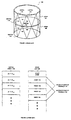
- figure 1 shows object 100 that has been divided into strips and triangles in accordance with this technique.
- Strips 101 and 103 are immediately adjacent to one another and define object 100.
- Each strip is further partitioned into a set of triangles.
- strip 101 is divided into triangles 115, 125, 135 and so on, while strip 103 is partitioned into triangles 145, 155, 165 and so on.
- the triangles are positioned within a three-dimensional space defined by the object to be rendered. Therefore, the triangles need not reside in the same plane and, indeed, are likely to be non-planar with respect to one another as they are positioned around the three-dimensional object.
- FIG 2 Shown in figure 2 is a known data structure 200 for storing a strips and fans representation of an object.
- the triangles of the representation have been deconstructed into a vertex array 210 and an index list 200.
- Vertex array 210 stores information related to the vertices of the triangles.
- each entry of vertex array 210 contains, among other parameters, the three-dimensional coordinates of a vertex.
- the three-dimensional coordinates of vertices 116, 118, 120, and 122 are shown as entries in array 210.
- the vertices of an object are ordinarily grouped together, but are in no particular order within the group.
- the order of the entries corresponds to vertices 122, 118, 120, and 116.
- the coordinates stored in array 210 describe the positioning of the vertices with respect to one another in a three-dimensional space wholly defined by object 100. In other words, the coordinates define only the surface of the object, not the surrounding space.
- Index list 220 stores instructions for reconnecting the vertices of the triangles within the strips of object 100. For example, the instructions relating to the reconstruction of triangle 115 are shown in index list 220. Since triangle 115 is considered, in this example, to be the first triangle in strip 101, instructions for this triangle are immediately preceded by a "start strip” instruction. The number of vertices representing a strip is encoded in the respective "start strip” instruction. This is followed by the next three instructions, which correspond to vertices 116, 118, and 120. Each instruction pair 116-118, 118-120, and 120-116, represent a connection between vertices. Thus triangle 115 is reconstructed.
- each remaining triangle within the strip builds upon the preceding triangle and may be defined by reference to one additional vertex.
- triangle 125 shares vertices 118 and 120 with triangle 115 and may easily be defined with an additional reference to vertex 122.
- the technique described above capitalizes on this fact by grouping and processing the connections between vertices 118, 120, and 122 as the third through fifth instructions of index list 220. Since vertex 118 and vertex 120 have been connected in the reconstruction of triangle 115, additional connections to vertex 122 need only be made.
- Triangle 135 and those following in strip 101 are reconstructed in a similar fashion.
- each vertex is positioned within a three-dimensional space by a geometric transformation such as a translation, a rotation, a scaling, or a combination of these functions. This transformation is performed in order to track the motions of the object to be rendered.
- Each vertex then may be optionally lighted before being projected from its three-dimensional space into a two-dimensional perspective. The result of this operation is to project each of the vertices in object 100 onto a flat screen that may then be rendered using a standard rendering pipeline.
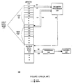
- Shown in figure 3 is a known pipeline system 300 for rendering three-dimensional objects from graphical data stored in a data structure like that shown in figure 2.
- Memory 310 is divided into an input database 311 that includes index list 220 and vertex array 210, and an output database 313 that stores transformed triangles.
- vertex array 210 and index list 220 store the graphical data of an object that has been modeled using the strips and fans technique.
- geometry processor 320 initiates the rendering of a stored image by entering the corresponding rendering routine. Part of this routine is responsible for collecting all of the input data required to reconstruct each triangle of the object.
- the input data consists of index list 220, which is referenced via pointer 321, and vertex array 210, which is referenced by pointer 323.
- pointer 321 corresponds to the start of instructions for rendering object 100.
- each instruction in the index list is either a start-strip command or an instruction to reference an entry in the vertex array.
- processor 320 reads the number of vertices in the strip from the command and enters this number into a count register. It then specifies in a format register whether a strip or a fan is to be rendered, and indicates in a continuation register whether vertices from the last strip are to be carried over into the next.
- processor 320 In response to accessing an index instruction in index list 220, processor 320 is instructed to read, via pointer 323, a corresponding vertex-array entry, entry 211 for example.
- vertex-array entry 211 stores the three-dimensional coordinates of a triangle vertex.
- the processor In order to determine the two-dimensional screen coordinates for the vertex, the processor, in accordance with the motions of the object described by the user or the software application, reads and transforms the coordinates from vertex-array entry 211 and lights the vertex in accordance with the lighting, blocking, and shadowing parameters created by other rendered objects within the locale of the vertex in question. The result is to transform the three-dimensional model coordinates into a set of two-dimensional transformed, or screen, coordinates.
- the screen coordinates are then used by processor 320 to assemble the respective triangle, which is then stored in output database 313 of memory 310.
- the triangle is read by renderer 330 as needed and rendered on screen 340, thus producing the screen perspective viewed by the user.
- this method produces redundancies in the processing of data, resulting in (1) decreased rendering speed due to the increased number of required computation cycles, (2) greater memory requirements due to the storage of assembled triangles which contain redundant data, and (3) inefficient use of the available memory bandwidth due to the passage of redundant data and assembled triangles between elements of the system.
- the present invention provides a method for arranging graphical data stored as an array of vertices and a list of indices, comprising:
- the present invention also provides a system for rendering an image stored as an array of vertices and a list of indices, comprising:
- a processor first generates an output array by transforming and lighting each model vertex in an array of model vertices.
- a polygon engine then reads a series of instructions from a list of indices, wherein each instruction references a transformed vertex in the output array.
- the list of indices are ordered such that any ordered pair of indices indicates that a connection should be made between the corresponding transformed vertices stored in the output array.
- Memory 410 is divided into vertex data base 411, main command list 413, setup list 414, and index list 220.
- Vertex database 411 is in turn divided into vertex array 210 and output array 412.
- Vertex array 210 and index list 220 are structured in a manner as described in figure 2. It is noted that memory 410 may contain multiple pairs of index lists and vertex arrays, each pair containing information for an image to be rendered.
- processor 420 In response to receiving a command and a vertex count from a user or a software application, processor 420 reads the entry indicated by pointer 461 from vertex array 210. This entry contains either a "start strip” command or an index instruction. A "start strip” command indicates that the processing of the next strip is to be initiated and contains a count value indicating the number of vertices in the strip to be connected. As discussed above, an index instruction points to an entry containing vertex parameters, including the three-dimensional coordinates of a vertex of a triangle used to model the object to be rendered. Upon reading 462 the entry from vertex array 210, processor 420 transforms and lights the vertex in accordance with the motions of the object as defined by the software application or user.
- the software application or user may instruct the image to be rendered frame-by-frame through a dive, a roll, or any other motion made by an airplane.
- the transformation and lighting process must take into consideration other objects, such as clouds for example, that affect the appearance of the object to be rendered.
- the result of these processes is the two-dimensional screen equivalent of the three-dimensionally described vertex.
- each vertex-array entry of the object to be rendered is processed. This process continues until the end of vertex array 210 is encountered, indicating that each vertex of the object to be rendered has been transformed and lighted. Note that the end of vertex array 210 is given by the vertex count value.
- processor 420 places three pieces of information in the main command list 413.
- the first piece of information is a subroutine call that references setup list 414 which contains special instruction for the renderer to initialize datapath modes.
- the second piece of information is a special instruction indicating an address pointer to the start of output array 412.
- the third piece of information is a subroutine call to index list 220, which contains instructions for connecting the vertices of the object to be rendered. This process is repeated for each output array that has been readied by processor 420 for rendering by renderer 430, and may result in a lengthy command list 413.
- Processor 420 signals renderer 430 over communication line 466 that an output array and an associated index list is ready for rendering. Specifically, processor 420 sends renderer 430 two pointers. The first pointer, a "write pointer", indicates the end of main command list 413, while the second pointer, a "read pointer', indicates the start of the same list. In this manner, processor 420 updates renderer 430 as to the current status of command list 413. Polygon renderer 430 constantly monitors the state of its internal read pointer in relation to the write pointer written above. Whenever these pointers differ, renderer 430 reads instructions from the main command list 413, incrementing the internal read pointer for each instruction.
- renderer 430 detects a difference between the read and write pointers, it reads list main command list 413 at 467 and decodes the next three commands. First, renderer 430 processes the subroutine call for setup list 414. Secondly, renderer 430 encounters the start address of outpay array 412. After reading this address, renderer 430 receives the subroutine call to index list 220 at pointer 471. Upon reading the call, renderer 430 jumps to this address and starts processing the instructions comprising index list 220.
- each entry in index list 220 is either a "start strip” command or is an instruction to connect the next vertex with the preceding vertex, In this case, once the "start strip" instruction is processed, subsequent instructions reference entries in output array 412.
- renderer 430 reads the corresponding transformed vertex information from output array 412 as indicated by pointer 473. This step is preferably performed by storing in each of the instructions of index list 220 an offset value that, once added to the starting address of output array 412, references the transformed vertex.
- renderer 430 assembles each triangle from the transformed vertices of output array 412, the triangles are passed to screen 440 for display. It is noted that index list 220 is processed sequentially, and once the initial setups have taken place, renderer 430 assembles triangles by referencing index list 220 and output array 412.
- processor 420 need only transform and light each vertex once, while processor 320 may be required to repeatedly transform and light the same vertices.
- This difference is attributed to the slightly increased burden placed on renderer 430, which not only retrieves and sends triangles to a screen as does renderer 330, but must also assemble them from the vertices of output array 412.
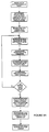
- FIG. 5A shows a flow diagram of the role of processor 420 in a method for rendering a three-dimensional graphical image in accordance with the present invention.
- a software application initiates the rendering of an object.
- the application is an interactive video game operating on processor 420 and the rendering may be in response to a user's movement of a joy stick, indicating that an object is to be moved and necessitating a refreshed image of the object in the new position.
- the application provides processor 420 with two pointers, one to the corresponding vertex array such as array 210, and the second to an output array such as array 412, and a vertex count.
- the vertex count is indicative of the number of vertices arrayed upon the surface of the object.
- Processor 420 receives these address pointers and the vertex count in step 504.
- processor 420 sets an internal count register to zero. The count register is used by processor 420 to determine when the last vertex of the object has been processed.
- processor 420 begins to sequentially process the vertices of vertex array 210 by reading the vertex-array entry indicated by the pointer read in step 504. The entry contains the model coordinates of a single vertex of the object.
- the processor transforms and lights the vertex in accordance with the movement of the object as described by the software application.
- step 512 the processor stores the transformed coordinates of the vertex in output array 412 located at the address provided by the application in step 504.
- step 514 the processor increments the internal count register, indicating that a vertex has been processed.
- step 516 the value stored in the internal count register is compared with the vertex count in order to determine whether the last of the entries in vertex array 210 has been processed. If not, the process loops back to step 508 and steps 508 through 516 are repeated for the next entry in array 210.
- processor 420 may process the entries in any manner as long as each entry is processed, it is most efficient for the processor to sequentially process the entries from the start of the array to the end.
- processor 420 places the starting address of output array 412 in the main command list 413.
- the main command list stores the starting address or addresses of the output arrays that have been completed by processor 420 and are ready for assembly and rendering.
- processor 420 places two subroutine instructions in main command list 413.
- the first subroutine command instructs renderer 430 to jump to the setup command list 414, while the second subroutine command instructs renderer 430 to jump to the corresponding index list of assembly instructions.
- Processor 420 completes the processing of the vertices in step 520 by loading in a register of renderer 430 pointer 467 to main command list 413 and, in step 522, by sending renderer 430 a start command over communication line 466.
- FIG. 5B shows a flow diagram of the role of renderer 430 in a method for rendering a three-dimensional graphical image in accordance with the present invention.
- Renderer 430 receives the start command from processor 420 in step 524 and reads in step 526 pointer 467 placed in a register by processor 420 in step 526.
- the pointer references main command list 413, from which renderer 430 reads the call to setup list 414 in step 528.
- the renderer performs the setup list instructions to initialize the datapath modes.
- the renderer returns to the main command list and reads the start address of output array 412.
- the renderer reads the call to index list 220.
- the renderer sets an internal count register to zero. The count register is used to track the number of processed index instructions and to determine when a strip is finished by comparing the count with the index count supplied in the "start strip" command. This command and the index count are read by the renderer in step 538.
- the renderer begins the actual rendering of a strip by reading the first index instruction from index list 220.
- This instruction stores an offset value that, once added to the starting address of output array 412, references the parameters of a transformed vertex of a triangle that is used to render the object to be depicted.
- the renderer reads in step 542 the vertex parameters stored in the referenced entry of output array 412. It is noted that the instruction contains a reference to the transformed coordinates of one vertex. Whether the vertex may be connected to the preceding vertex of the strip depends upon whether the vertex is the first in a strip. It is noted that the index instructions of index list 220 do not necessarily instruct the renderer to read the output-array entries sequentially.
- step 544 the renderer increments the internal count register discussed above.
- step 546 it is determined whether the referenced vertex is the first in a strip. If it is determined that the referenced vertex is the first in a strip, it is necessary to fetch a second vertex from the output array in steps 540 and 542, since step 548 requires two vertices to connect.
- step 548 renderer 430 connects the two vertices and partially assembles the triangle.
- step 550 renderer 430 determines whether the last instruction in the strip has been processed by comparing the internal count register to the index count. If not, the process continues at step 540 and renderer 430 repeats steps 540 through 550 for the next index instruction in index list 220.
- step 552 the renderer determines whether the last strip in the object has been processed. If not, steps 536 through 552 are repeated for the next strip. Notably, processor 420 need not transform and light the vertices for the next strip, since the transformations are stored in output array 412. Once the last strip has been assembled, the object is projected on screen 440 in step 554.
- the above system and method reduce the three inefficiencies identified in the prior art.
- (1) the number of computation cycles required of the processor is reduced because each vertex is transformed and lighted only once per rendering. Thus redundant processing is reduced.
- (2) the assembled triangles are not stored and therefore the memory requirements are reduced.
- (3) the memory bandwidth of the system is more efficiently used, since data redundancy has been minimized and since the data sent from one element to another has been atomized.
Abstract
Description
- The invention relates to a method and apparatus of arranging graphical data such as rendering of three-dimensional computer images, and specifically to the pipelining of image data for three-dimensional objects.
- A known method for graphically modelling an object is to approximate the curvature of the object by dividing the object into a series of adjacent strips or fans and then dividing each strip or fan into a series of adjacent triangles whose vertices lay on the edge of the strip or fan. For example, figure 1 shows
object 100 that has been divided into strips and triangles in accordance with this technique.Strips object 100. Each strip is further partitioned into a set of triangles. For example,strip 101 is divided intotriangles strip 103 is partitioned intotriangles - Shown in figure 2 is a known data structure 200 for storing a strips and fans representation of an object. The triangles of the representation have been deconstructed into a
vertex array 210 and an index list 200.Vertex array 210 stores information related to the vertices of the triangles. Specifically, each entry ofvertex array 210 contains, among other parameters, the three-dimensional coordinates of a vertex. For example, the three-dimensional coordinates ofvertices array 210. It is noted that the vertices of an object are ordinarily grouped together, but are in no particular order within the group. For example, in figure 2 the order of the entries corresponds tovertices array 210 describe the positioning of the vertices with respect to one another in a three-dimensional space wholly defined byobject 100. In other words, the coordinates define only the surface of the object, not the surrounding space. -
Index list 220 stores instructions for reconnecting the vertices of the triangles within the strips ofobject 100. For example, the instructions relating to the reconstruction oftriangle 115 are shown inindex list 220. Sincetriangle 115 is considered, in this example, to be the first triangle instrip 101, instructions for this triangle are immediately preceded by a "start strip" instruction. The number of vertices representing a strip is encoded in the respective "start strip" instruction. This is followed by the next three instructions, which correspond tovertices triangle 115 is reconstructed. - Once the initial triangle in a strip is complete, a degree of efficiency is achieved by the strips and fans method. This is because each remaining triangle within the strip builds upon the preceding triangle and may be defined by reference to one additional vertex. For example, continuing with
strip 101,triangle 125shares vertices triangle 115 and may easily be defined with an additional reference tovertex 122. The technique described above capitalizes on this fact by grouping and processing the connections betweenvertices index list 220. Sincevertex 118 andvertex 120 have been connected in the reconstruction oftriangle 115, additional connections tovertex 122 need only be made.Triangle 135 and those following instrip 101 are reconstructed in a similar fashion. - As each triangle is being reconstructed, the corresponding vertices must have certain operations performed on them in order to position them properly on the screen. Firstly, each vertex is positioned within a three-dimensional space by a geometric transformation such as a translation, a rotation, a scaling, or a combination of these functions. This transformation is performed in order to track the motions of the object to be rendered. Each vertex then may be optionally lighted before being projected from its three-dimensional space into a two-dimensional perspective. The result of this operation is to project each of the vertices in
object 100 onto a flat screen that may then be rendered using a standard rendering pipeline. - Shown in figure 3 is a known
pipeline system 300 for rendering three-dimensional objects from graphical data stored in a data structure like that shown in figure 2.Memory 310 is divided into aninput database 311 that includesindex list 220 andvertex array 210, and anoutput database 313 that stores transformed triangles. As described above,vertex array 210 andindex list 220 store the graphical data of an object that has been modeled using the strips and fans technique. In response to a command from a user or a software application,geometry processor 320 initiates the rendering of a stored image by entering the corresponding rendering routine. Part of this routine is responsible for collecting all of the input data required to reconstruct each triangle of the object. The input data consists ofindex list 220, which is referenced viapointer 321, andvertex array 210, which is referenced bypointer 323. At the outset,pointer 321 corresponds to the start of instructions for renderingobject 100. As described above, each instruction in the index list is either a start-strip command or an instruction to reference an entry in the vertex array. In response to receiving a start-strip command,processor 320 reads the number of vertices in the strip from the command and enters this number into a count register. It then specifies in a format register whether a strip or a fan is to be rendered, and indicates in a continuation register whether vertices from the last strip are to be carried over into the next. In response to accessing an index instruction inindex list 220,processor 320 is instructed to read, viapointer 323, a corresponding vertex-array entry,entry 211 for example. As described above, vertex-array entry 211 stores the three-dimensional coordinates of a triangle vertex. In order to determine the two-dimensional screen coordinates for the vertex, the processor, in accordance with the motions of the object described by the user or the software application, reads and transforms the coordinates from vertex-array entry 211 and lights the vertex in accordance with the lighting, blocking, and shadowing parameters created by other rendered objects within the locale of the vertex in question. The result is to transform the three-dimensional model coordinates into a set of two-dimensional transformed, or screen, coordinates. Once the coordinates of a vertex have been transformed and lighted, the screen coordinates are then used byprocessor 320 to assemble the respective triangle, which is then stored inoutput database 313 ofmemory 310. The triangle is read byrenderer 330 as needed and rendered onscreen 340, thus producing the screen perspective viewed by the user. - Although the technique and system described above efficiently reconstruct subsequent triangles by building on an initial triangle, this efficiency is limited to the reconstruction of triangles within a strip. For example, with reference to figure 1, this can be seen in the reconstruction of
triangle 145.Triangle 145shares vertices triangle 115 and could easily be reconstructed by further reference tovertex 124. However, the described method buildstriangle 145 by reprocessing and reconnectingvertices processor 320.Processor 320 must twice read, twice transform, and twice light the coordinates ofmodel vertices system 300, this method produces redundancies in the processing of data, resulting in (1) decreased rendering speed due to the increased number of required computation cycles, (2) greater memory requirements due to the storage of assembled triangles which contain redundant data, and (3) inefficient use of the available memory bandwidth due to the passage of redundant data and assembled triangles between elements of the system. Thus a need exists for a method and system for processing index instructions and vertex data in a manner that reduces data redundancies and increases rendering speed. - The present invention provides a method for arranging graphical data stored as an array of vertices and a list of indices, comprising:
- generating an output array, further comprising for each output-array entry:
- selecting a corresponding vertex from the array of vertices;
- transforming the vertex; and
- storing the transformed vertex in the output-array entry;
- reading a first index from the list of indices;
- reading from the output array a first transformed vertex referenced by the first index;
- reading a second index from the list of indices;
- reading from the output array a second transformed vertex referenced by the second index; and
- associating the second transformed vertex with the first transformed vertex.
-
- The present invention also provides a system for rendering an image stored as an array of vertices and a list of indices, comprising:
- a geometry processor for transforming each vertex in the array of vertices;
- an output array for storing each transformed vertex generated by the geometry processor;
- a renderer for associating pairs of transformed vertices in accordance with the list of indices.
-
- We will describe a method and system for connecting the vertices of a strips and fans data structure for rendering a three-dimensional object. A processor first generates an output array by transforming and lighting each model vertex in an array of model vertices. A polygon engine then reads a series of instructions from a list of indices, wherein each instruction references a transformed vertex in the output array. The list of indices are ordered such that any ordered pair of indices indicates that a connection should be made between the corresponding transformed vertices stored in the output array.
-
- Figure 1 shows a known technique for graphically describing an object.
- Figure 2 shows a known data structure for storing graphical information of a known technique for describing an object.
- Figure 3 shows a known system for rendering a graphical description of an object.
- Figure 4 shows a system in accordance with the present invention for rendering a graphical description of an object.
- Figures 5A and 5B show a flow diagram of a method in accordance with the present invention for rendering a graphical description of an object.
-
- Shown in figure 4 is
system 400, an embodiment of the invention.Memory 410 is divided intovertex data base 411,main command list 413,setup list 414, andindex list 220.Vertex database 411 is in turn divided intovertex array 210 andoutput array 412.Vertex array 210 andindex list 220 are structured in a manner as described in figure 2. It is noted thatmemory 410 may contain multiple pairs of index lists and vertex arrays, each pair containing information for an image to be rendered. - In response to receiving a command and a vertex count from a user or a software application,
processor 420 reads the entry indicated bypointer 461 fromvertex array 210. This entry contains either a "start strip" command or an index instruction. A "start strip" command indicates that the processing of the next strip is to be initiated and contains a count value indicating the number of vertices in the strip to be connected. As discussed above, an index instruction points to an entry containing vertex parameters, including the three-dimensional coordinates of a vertex of a triangle used to model the object to be rendered. Upon reading 462 the entry fromvertex array 210,processor 420 transforms and lights the vertex in accordance with the motions of the object as defined by the software application or user. For example, ifobject 100 is an airplane or a portion of an airplane, the software application or user may instruct the image to be rendered frame-by-frame through a dive, a roll, or any other motion made by an airplane. In addition to the motion of the object itself, the transformation and lighting process must take into consideration other objects, such as clouds for example, that affect the appearance of the object to be rendered. The result of these processes is the two-dimensional screen equivalent of the three-dimensionally described vertex. Once the vertex has been transformed and lighted,processor 420 stores the transformed vertex inoutput array 412 at entry 464 indicated bypointer 463 which is supplied by the application.Processor 420 thenincrements pointers vertex array 210 is encountered, indicating that each vertex of the object to be rendered has been transformed and lighted. Note that the end ofvertex array 210 is given by the vertex count value. - At the end of processing
vertex array 210,processor 420 places three pieces of information in themain command list 413. The first piece of information is a subroutine call that referencessetup list 414 which contains special instruction for the renderer to initialize datapath modes. The second piece of information is a special instruction indicating an address pointer to the start ofoutput array 412. The third piece of information is a subroutine call toindex list 220, which contains instructions for connecting the vertices of the object to be rendered. This process is repeated for each output array that has been readied byprocessor 420 for rendering byrenderer 430, and may result in alengthy command list 413. -
Processor 420 signals renderer 430 overcommunication line 466 that an output array and an associated index list is ready for rendering. Specifically,processor 420 sends renderer 430 two pointers. The first pointer, a "write pointer", indicates the end ofmain command list 413, while the second pointer, a "read pointer', indicates the start of the same list. In this manner,processor 420 updates renderer 430 as to the current status ofcommand list 413.Polygon renderer 430 constantly monitors the state of its internal read pointer in relation to the write pointer written above. Whenever these pointers differ,renderer 430 reads instructions from themain command list 413, incrementing the internal read pointer for each instruction. - Continuing with the example, once
renderer 430 detects a difference between the read and write pointers, it reads listmain command list 413 at 467 and decodes the next three commands. First,renderer 430 processes the subroutine call forsetup list 414. Secondly,renderer 430 encounters the start address ofoutpay array 412. After reading this address,renderer 430 receives the subroutine call toindex list 220 at pointer 471. Upon reading the call,renderer 430 jumps to this address and starts processing the instructions comprisingindex list 220. - As discussed above, each entry in
index list 220 is either a "start strip" command or is an instruction to connect the next vertex with the preceding vertex, In this case, once the "start strip" instruction is processed, subsequent instructions reference entries inoutput array 412. In response to each of the subsequent instructions,renderer 430 reads the corresponding transformed vertex information fromoutput array 412 as indicated bypointer 473. This step is preferably performed by storing in each of the instructions ofindex list 220 an offset value that, once added to the starting address ofoutput array 412, references the transformed vertex. Asrenderer 430 assembles each triangle from the transformed vertices ofoutput array 412, the triangles are passed to screen 440 for display. It is noted thatindex list 220 is processed sequentially, and once the initial setups have taken place,renderer 430 assembles triangles by referencingindex list 220 andoutput array 412. - The system described above and shown in figure 4 places less of a burden on
processor 420 than that placed onprocessor 320 by the known system shown in figure 3. This is becauseprocessor 420 need only transform and light each vertex once, whileprocessor 320 may be required to repeatedly transform and light the same vertices. This difference is attributed to the slightly increased burden placed onrenderer 430, which not only retrieves and sends triangles to a screen as doesrenderer 330, but must also assemble them from the vertices ofoutput array 412. - Figure 5A shows a flow diagram of the role of
processor 420 in a method for rendering a three-dimensional graphical image in accordance with the present invention. Instep 502, a software application initiates the rendering of an object. Typically, the application is an interactive video game operating onprocessor 420 and the rendering may be in response to a user's movement of a joy stick, indicating that an object is to be moved and necessitating a refreshed image of the object in the new position. As part of the initiation of the rendering, the application providesprocessor 420 with two pointers, one to the corresponding vertex array such asarray 210, and the second to an output array such asarray 412, and a vertex count. The vertex count is indicative of the number of vertices arrayed upon the surface of the object.Processor 420 receives these address pointers and the vertex count instep 504. Instep 506,processor 420 sets an internal count register to zero. The count register is used byprocessor 420 to determine when the last vertex of the object has been processed. Instep 508,processor 420 begins to sequentially process the vertices ofvertex array 210 by reading the vertex-array entry indicated by the pointer read instep 504. The entry contains the model coordinates of a single vertex of the object. Instep 510, the processor transforms and lights the vertex in accordance with the movement of the object as described by the software application. In step 512, the processor stores the transformed coordinates of the vertex inoutput array 412 located at the address provided by the application instep 504. In step 514, the processor increments the internal count register, indicating that a vertex has been processed. Instep 516, the value stored in the internal count register is compared with the vertex count in order to determine whether the last of the entries invertex array 210 has been processed. If not, the process loops back to step 508 andsteps 508 through 516 are repeated for the next entry inarray 210. Althoughprocessor 420 may process the entries in any manner as long as each entry is processed, it is most efficient for the processor to sequentially process the entries from the start of the array to the end. - In step 518, which is reached once all of the entries in
array 210 have been transformed,processor 420 places the starting address ofoutput array 412 in themain command list 413. The main command list stores the starting address or addresses of the output arrays that have been completed byprocessor 420 and are ready for assembly and rendering. In addition to placing the output array address in the main command list,processor 420 places two subroutine instructions inmain command list 413. The first subroutine command instructsrenderer 430 to jump to thesetup command list 414, while the second subroutine command instructsrenderer 430 to jump to the corresponding index list of assembly instructions.Processor 420 completes the processing of the vertices in step 520 by loading in a register ofrenderer 430pointer 467 tomain command list 413 and, in step 522, by sending renderer 430 a start command overcommunication line 466. - Figure 5B shows a flow diagram of the role of
renderer 430 in a method for rendering a three-dimensional graphical image in accordance with the present invention.Renderer 430 receives the start command fromprocessor 420 in step 524 and reads in step 526pointer 467 placed in a register byprocessor 420 in step 526. The pointer referencesmain command list 413, from which renderer 430 reads the call tosetup list 414 in step 528. In step 530, the renderer performs the setup list instructions to initialize the datapath modes. In step 532, the renderer returns to the main command list and reads the start address ofoutput array 412. In step 534, the renderer reads the call toindex list 220. Instep 536, the renderer sets an internal count register to zero. The count register is used to track the number of processed index instructions and to determine when a strip is finished by comparing the count with the index count supplied in the "start strip" command. This command and the index count are read by the renderer in step 538. - In step 540, the renderer begins the actual rendering of a strip by reading the first index instruction from
index list 220. This instruction stores an offset value that, once added to the starting address ofoutput array 412, references the parameters of a transformed vertex of a triangle that is used to render the object to be depicted. The renderer reads in step 542 the vertex parameters stored in the referenced entry ofoutput array 412. It is noted that the instruction contains a reference to the transformed coordinates of one vertex. Whether the vertex may be connected to the preceding vertex of the strip depends upon whether the vertex is the first in a strip. It is noted that the index instructions ofindex list 220 do not necessarily instruct the renderer to read the output-array entries sequentially. In step 544, the renderer increments the internal count register discussed above. In step 546, it is determined whether the referenced vertex is the first in a strip. If it is determined that the referenced vertex is the first in a strip, it is necessary to fetch a second vertex from the output array in steps 540 and 542, sincestep 548 requires two vertices to connect. Instep 548,renderer 430 connects the two vertices and partially assembles the triangle. In step 550,renderer 430 determines whether the last instruction in the strip has been processed by comparing the internal count register to the index count. If not, the process continues at step 540 andrenderer 430 repeats steps 540 through 550 for the next index instruction inindex list 220. Once the last instruction has been processed, the strip has been completely transformed and assembled. In step 552, the renderer determines whether the last strip in the object has been processed. If not, steps 536 through 552 are repeated for the next strip. Notably,processor 420 need not transform and light the vertices for the next strip, since the transformations are stored inoutput array 412. Once the last strip has been assembled, the object is projected onscreen 440 in step 554. - The above system and method reduce the three inefficiencies identified in the prior art. With respect to (1) the number of computation cycles required of the processor is reduced because each vertex is transformed and lighted only once per rendering. Thus redundant processing is reduced. With respect to (2) the assembled triangles are not stored and therefore the memory requirements are reduced. With respect to (3) the memory bandwidth of the system is more efficiently used, since data redundancy has been minimized and since the data sent from one element to another has been atomized.
Claims (12)
- A method for arranging graphical data stored as an array of vertices and a list of indices, comprising:generating an output array, further comprising for each output-array entry:selecting a corresponding vertex from the array of vertices;transforming the vertex; andstoring the transformed vertex in the output-array entry;reading a first index from the list of indices;reading from the output array a first transformed vertex referenced by the first index;reading a second index from the list of indices;reading from the output array a second transformed vertex referenced by the second index; andassociating the second transformed vertex with the first transformed vertex.
- The method of claim 1, wherein the step of transforming further comprises transforming the spatial coordinates of the vertex into the screen coordinates of a transformed vertex.
- The method of claim 1, further comprising rendering the association between the first transformed vertex and the second transformed vertex as a line.
- The method of claim 1, wherein the array of vertices stores the spatial coordinates of a set of vertices arrayed upon the surface of an object.
- The method of claim 1, wherein the list of indices stores the connections between a set of vertices arrayed upon the surface of an object.
- The method of claim 5, wherein the indices of the list of indices are arranged in the order of strips arrayed upon the surface of an object.
- A system for rendering an image stored as an array of vertices and a list if indices, comprising:a geometry processor for transforming each vertex in the array of vertices;an output array for storing each transformed vertex generated by the geometry processor;a renderer for associating pairs of transformed vertices in accordance with the list of indices.
- The system of claim 7, wherein the geometry processor is for transforming the spatial coordinates of each vertex in the array of vertices into screen coordinates.
- The system of claim 7 further comprising a screen for rendering the association between a pair of transformed vertices as a line.
- The system of claim 7, wherein the array of vertices stores the spatial coordinates of a set of vertices arrayed upon the surface of an object.
- The system of claim 7, wherein list of indices stores the connections between a set of vertices arrayed upon the surface of an object.
- The system of claim 11, wherein the indices of the list of indices are arranged in the order of strips arrayed upon the surface of an object.
Applications Claiming Priority (2)
| Application Number | Priority Date | Filing Date | Title |
|---|---|---|---|
| US9714 | 1995-12-27 | ||
| US09/009,714 US7190362B1 (en) | 1998-01-20 | 1998-01-20 | System and method for organizing data for a 3-dimensional graphics pipeline |
Publications (2)
| Publication Number | Publication Date |
|---|---|
| EP0930582A2 true EP0930582A2 (en) | 1999-07-21 |
| EP0930582A3 EP0930582A3 (en) | 2001-02-21 |
Family
ID=21739300
Family Applications (1)
| Application Number | Title | Priority Date | Filing Date |
|---|---|---|---|
| EP99300357A Withdrawn EP0930582A3 (en) | 1998-01-20 | 1999-01-19 | A method and apparatus for arranging graphical data |
Country Status (3)
| Country | Link |
|---|---|
| US (1) | US7190362B1 (en) |
| EP (1) | EP0930582A3 (en) |
| JP (1) | JPH11316854A (en) |
Cited By (4)
| Publication number | Priority date | Publication date | Assignee | Title |
|---|---|---|---|---|
| EP1255227A1 (en) * | 2001-04-27 | 2002-11-06 | STMicroelectronics Limited | Vertices index processor |
| US7423644B2 (en) | 2004-03-02 | 2008-09-09 | Ati Technologies Inc. | Method and apparatus for dual pass adaptive tessellation |
| US7639252B2 (en) | 2004-08-11 | 2009-12-29 | Ati Technologies Ulc | Unified tessellation circuit and method therefor |
| US8482559B2 (en) | 2002-11-04 | 2013-07-09 | Ati Technologies Ulc | Method and apparatus for triangle tessellation |
Families Citing this family (6)
| Publication number | Priority date | Publication date | Assignee | Title |
|---|---|---|---|---|
| US7593010B2 (en) * | 2003-09-18 | 2009-09-22 | Microsoft Corporation | Software-implemented transform and lighting module and pipeline for graphics rendering on embedded platforms using a fixed-point normalized homogenous coordinate system |
| US8134566B1 (en) * | 2006-07-28 | 2012-03-13 | Nvidia Corporation | Unified assembly instruction set for graphics processing |
| US8188999B2 (en) * | 2008-06-17 | 2012-05-29 | Qualcomm Incorporated | Method and apparatus for organizing object geometry for spatial and memory coherency and optimal rendering |
| JP4721472B2 (en) * | 2009-03-30 | 2011-07-13 | 株式会社バンダイナムコゲームス | Image generation system and information storage medium |
| JP5726332B2 (en) * | 2012-01-06 | 2015-05-27 | 三菱電機株式会社 | Drawing control device |
| CN111524066B (en) * | 2020-01-13 | 2022-12-23 | 北京理工大学 | High-speed compression imaging method based on sliding window type data processing |
Citations (6)
| Publication number | Priority date | Publication date | Assignee | Title |
|---|---|---|---|---|
| EP0454136A2 (en) * | 1990-04-26 | 1991-10-30 | Honeywell Inc. | Method and apparatus for generating three dimensional graphic symbols |
| EP0531157A2 (en) * | 1991-09-06 | 1993-03-10 | Canon Kabushiki Kaisha | Three dimensional graphics processing |
| FR2694427A1 (en) * | 1992-08-03 | 1994-02-04 | Ball Corp | Computer graphics display appts. - stores objects as indexed array of polygon apexes and processes array to define object in space |
| US5485559A (en) * | 1990-06-13 | 1996-01-16 | Hitachi, Ltd. | Parallel graphics processor with graphics command distributor and command sequencing method |
| US5561749A (en) * | 1994-12-02 | 1996-10-01 | General Electric Company | Modeling of surfaces employing polygon strips |
| EP0757333A2 (en) * | 1995-08-04 | 1997-02-05 | Sun Microsystems, Inc. | 3D image decoding |
Family Cites Families (3)
| Publication number | Priority date | Publication date | Assignee | Title |
|---|---|---|---|---|
| US5793371A (en) * | 1995-08-04 | 1998-08-11 | Sun Microsystems, Inc. | Method and apparatus for geometric compression of three-dimensional graphics data |
| US5905507A (en) * | 1996-01-16 | 1999-05-18 | International Business Machines Corporation | Compression of geometric models using spanning trees |
| US5896139A (en) * | 1996-08-01 | 1999-04-20 | Platinum Technology Ip, Inc. | System and method for optimizing a scene graph for optimizing rendering performance |
-
1998
- 1998-01-20 US US09/009,714 patent/US7190362B1/en not_active Expired - Fee Related
-
1999
- 1999-01-19 EP EP99300357A patent/EP0930582A3/en not_active Withdrawn
- 1999-01-20 JP JP11051307A patent/JPH11316854A/en active Pending
Patent Citations (6)
| Publication number | Priority date | Publication date | Assignee | Title |
|---|---|---|---|---|
| EP0454136A2 (en) * | 1990-04-26 | 1991-10-30 | Honeywell Inc. | Method and apparatus for generating three dimensional graphic symbols |
| US5485559A (en) * | 1990-06-13 | 1996-01-16 | Hitachi, Ltd. | Parallel graphics processor with graphics command distributor and command sequencing method |
| EP0531157A2 (en) * | 1991-09-06 | 1993-03-10 | Canon Kabushiki Kaisha | Three dimensional graphics processing |
| FR2694427A1 (en) * | 1992-08-03 | 1994-02-04 | Ball Corp | Computer graphics display appts. - stores objects as indexed array of polygon apexes and processes array to define object in space |
| US5561749A (en) * | 1994-12-02 | 1996-10-01 | General Electric Company | Modeling of surfaces employing polygon strips |
| EP0757333A2 (en) * | 1995-08-04 | 1997-02-05 | Sun Microsystems, Inc. | 3D image decoding |
Cited By (5)
| Publication number | Priority date | Publication date | Assignee | Title |
|---|---|---|---|---|
| EP1255227A1 (en) * | 2001-04-27 | 2002-11-06 | STMicroelectronics Limited | Vertices index processor |
| US7170512B2 (en) | 2001-04-27 | 2007-01-30 | Stmicroelectronics Limited | Index processor |
| US8482559B2 (en) | 2002-11-04 | 2013-07-09 | Ati Technologies Ulc | Method and apparatus for triangle tessellation |
| US7423644B2 (en) | 2004-03-02 | 2008-09-09 | Ati Technologies Inc. | Method and apparatus for dual pass adaptive tessellation |
| US7639252B2 (en) | 2004-08-11 | 2009-12-29 | Ati Technologies Ulc | Unified tessellation circuit and method therefor |
Also Published As
| Publication number | Publication date |
|---|---|
| EP0930582A3 (en) | 2001-02-21 |
| JPH11316854A (en) | 1999-11-16 |
| US7190362B1 (en) | 2007-03-13 |
Similar Documents
| Publication | Publication Date | Title |
|---|---|---|
| US6046747A (en) | Graphics application programming interface avoiding repetitive transfer of texture mapping data | |
| US7508394B1 (en) | Systems and methods of multi-pass data processing | |
| US6700586B1 (en) | Low cost graphics with stitching processing hardware support for skeletal animation | |
| JP3184327B2 (en) | Three-dimensional graphics processing method and apparatus | |
| US4862392A (en) | Geometry processor for graphics display system | |
| US7098921B2 (en) | Method, system and computer program product for efficiently utilizing limited resources in a graphics device | |
| US5278948A (en) | Parametric surface evaluation method and apparatus for a computer graphics display system | |
| JP4890638B2 (en) | Method and apparatus for processing direct and indirect textures in a graphics system | |
| US5317682A (en) | Parametric curve evaluation method and apparatus for a computer graphics display system | |
| JP2011170881A (en) | Method and apparatus for using general three-dimensional (3d) graphics pipeline for cost effective digital image and video editing | |
| US20090195541A1 (en) | Rendering dynamic objects using geometry level-of-detail in a graphics processing unit | |
| US7190362B1 (en) | System and method for organizing data for a 3-dimensional graphics pipeline | |
| US20080266287A1 (en) | Decompression of vertex data using a geometry shader | |
| US20040207622A1 (en) | Efficient implementation of shading language programs using controlled partial evaluation | |
| US5745667A (en) | 3d graphics apparatus using texture images with displacement information | |
| US6177944B1 (en) | Two phase rendering for computer graphics | |
| US8482559B2 (en) | Method and apparatus for triangle tessellation | |
| US8004515B1 (en) | Stereoscopic vertex shader override | |
| Potmesil et al. | FRAMES: Software tools for modeling, rendering and animation of 3D scenes | |
| US6097395A (en) | Dynamic selection of lighting coordinates in a computer graphics system | |
| Ullner | Parallel machines for computer graphics | |
| Chen et al. | Depth-presorted triangle lists | |
| EP0889440B9 (en) | Method and apparatus for geometric compression of three-dimensional graphics | |
| US6304935B1 (en) | Method and system for data transmission in accelerated graphics port systems | |
| JP4017467B2 (en) | Triangular mesh data compression method and program |
Legal Events
| Date | Code | Title | Description |
|---|---|---|---|
| PUAI | Public reference made under article 153(3) epc to a published international application that has entered the european phase |
Free format text: ORIGINAL CODE: 0009012 |
|
| AK | Designated contracting states |
Kind code of ref document: A2 Designated state(s): DE FR GB |
|
| AX | Request for extension of the european patent |
Free format text: AL;LT;LV;MK;RO;SI |
|
| RIN1 | Information on inventor provided before grant (corrected) |
Inventor name: SABELLA, PAOLO Inventor name: SFARTI, ADRIAN Inventor name: LIU, MEI-CHI Inventor name: BAKER, NICHOLAS |
|
| PUAL | Search report despatched |
Free format text: ORIGINAL CODE: 0009013 |
|
| AK | Designated contracting states |
Kind code of ref document: A3 Designated state(s): AT BE CH CY DE DK ES FI FR GB GR IE IT LI LU MC NL PT SE |
|
| AX | Request for extension of the european patent |
Free format text: AL;LT;LV;MK;RO;SI |
|
| 17P | Request for examination filed |
Effective date: 20010615 |
|
| AKX | Designation fees paid |
Free format text: DE FR GB |
|
| 17Q | First examination report despatched |
Effective date: 20021119 |
|
| STAA | Information on the status of an ep patent application or granted ep patent |
Free format text: STATUS: THE APPLICATION IS DEEMED TO BE WITHDRAWN |
|
| 18D | Application deemed to be withdrawn |
Effective date: 20030602 |
|
| REG | Reference to a national code |
Ref country code: HK Ref legal event code: WD Ref document number: 1021048 Country of ref document: HK |