EP0932029B1 - Acoustic flow meter - Google Patents
Acoustic flow meter Download PDFInfo
- Publication number
- EP0932029B1 EP0932029B1 EP98121533A EP98121533A EP0932029B1 EP 0932029 B1 EP0932029 B1 EP 0932029B1 EP 98121533 A EP98121533 A EP 98121533A EP 98121533 A EP98121533 A EP 98121533A EP 0932029 B1 EP0932029 B1 EP 0932029B1
- Authority
- EP
- European Patent Office
- Prior art keywords
- fluid flow
- flow meter
- error signal
- transit time
- control value
- Prior art date
- Legal status (The legal status is an assumption and is not a legal conclusion. Google has not performed a legal analysis and makes no representation as to the accuracy of the status listed.)
- Expired - Lifetime
Links
Images


Classifications
-
- G—PHYSICS
- G01—MEASURING; TESTING
- G01F—MEASURING VOLUME, VOLUME FLOW, MASS FLOW OR LIQUID LEVEL; METERING BY VOLUME
- G01F1/00—Measuring the volume flow or mass flow of fluid or fluent solid material wherein the fluid passes through a meter in a continuous flow
- G01F1/66—Measuring the volume flow or mass flow of fluid or fluent solid material wherein the fluid passes through a meter in a continuous flow by measuring frequency, phase shift or propagation time of electromagnetic or other waves, e.g. using ultrasonic flowmeters
- G01F1/662—Constructional details
-
- G—PHYSICS
- G01—MEASURING; TESTING
- G01F—MEASURING VOLUME, VOLUME FLOW, MASS FLOW OR LIQUID LEVEL; METERING BY VOLUME
- G01F1/00—Measuring the volume flow or mass flow of fluid or fluent solid material wherein the fluid passes through a meter in a continuous flow
- G01F1/66—Measuring the volume flow or mass flow of fluid or fluent solid material wherein the fluid passes through a meter in a continuous flow by measuring frequency, phase shift or propagation time of electromagnetic or other waves, e.g. using ultrasonic flowmeters
- G01F1/667—Arrangements of transducers for ultrasonic flowmeters; Circuits for operating ultrasonic flowmeters
Definitions
- a pair of cells each having a piezoelectric transmitter and receiver, are placed so that an ultrasonic pulse can travel between the cells at an angle to the direction of fluid flow.
- each cell transmit an ultrasonic pulse for reception by the other both T u and T d can be measured.
- the device described in US 5,247,826 achieves the same result by arranging for a pair of ultrasonic transceivers, which are spaced apart in an elongate coiled tube through which gas can flow, to alternately operate as transmitters and receivers.
- the connections between the pulse generator 9, the timing means 10 and each of the transceivers 7,8 are switchable such that when the pulse generator 9 is switched to supply electrical pulses to the transceiver 7 the means 10 is switched to receive electrical signals only from the transceiver 8, and vice versa.
Description
- The present invention relates to an acoustic flow meter and in particular to an ultrasound flow meter useable in the monitoring of gas flow in breathing aid devices such as ventilators or respirators.
- Flow meters in which the time of flight of an acoustic (usually ultrasonic) pulse is used to determine the velocity (and hence the flow rate) of the fluid through which the pulse was transmitted are well known in the art. Devices, such as those described in WO 94/28790 and US 5,247,826, improve on this basic methodology by arranging for the transit times of ultrasonic pulses to be measured both upstream (Tu) and downstream (Td) of the fluid flow. These transit times are then supplied to a microprocessor which is set to calculate the fluid flow rate using standard algorithms. A thermometer is also included in both devices to measure the ambient temperature of the fluid. Since the velocity of sound in a medium changes with its temperature a more accurate transit time can be derived with a knowledge of the ambient temperature.
- In WO 94/28790 a pair of cells, each having a piezoelectric transmitter and receiver, are placed so that an ultrasonic pulse can travel between the cells at an angle to the direction of fluid flow. By having each cell transmit an ultrasonic pulse for reception by the other both Tu and Td can be measured. The device described in US 5,247,826 achieves the same result by arranging for a pair of ultrasonic transceivers, which are spaced apart in an elongate coiled tube through which gas can flow, to alternately operate as transmitters and receivers.
- A piezoelectric crystal does not emit a single pulse when energised with a single electrical pulse. Rather the crystal is caused to oscillate at a characteristic resonant frequency to emit a "packet" that comprises a number of pulses. The envelope of the transmitter signals decays rapidly with time, usually producing a train of six or so cycles. Thus small errors in the determination of the flow rate may result if the determination is made using different pulses from within the packet.
- A problem may therefore arise when the prior art devices are used in situations where it is critical to maintain flow rates within fine tolerances, for example in medical applications such as monitoring breathing gas flow rates in ventilators and respirators. In these applications flow meters must be capable of accurately and reliably detecting small changes in gas flow rates. However, prior art devices may record small changes which on the face of it look correct but which do not actually result from flow rate changes but rather from registering the arrival time of the wrong acoustic pulse from within a particular packet.
- It is an aim of the present invention to alleviate this problem by providing an acoustic flow meter in which such erroneous flow rates may be automatically identified.
- This may be achieved by a flow meter characterised according to
claim 1 in which an error signal indicator receives the measured transit times Tu and Td and compares a derivative (that is their sum or their difference) thereof with corresponding control values and, if their difference exceeds a corresponding predetermined threshold value, outputs an error signal. This error signal may be subsequently used, for example, to vary operating parameters of the flow meter to avoid such errors, to instruct circuitry to ignore the reading or to provide a sensible warning to an operator so that corrective measures may be manually implemented. - Usefully, especially when the flow meter is to measure continuous flows, the error signal indicator includes circuitry to form the sum of the transit times Tu and Td (which sum, because the fluid flow rate has equal but opposite effects on the transit times, should be constant for any flow rate); to compare it to a control value dependent on the expected sum, which may be a measured value or a calculated value (calculated for example by using the well known equation for the speed of sound in an ideal gas provided that the temperature and the composition of the gas is known); to output an error signal should the difference between the formed value and the control value exceed a predetermined threshold, which may be 0. In this way the flow meter can be continuously monitored for erroneous signals.
- The circuitry may, for example, be configured to measure the difference between the formed sum and a control value consisting of a previously formed sum and may additionally be adapted to replace the control value with the formed sum if the difference does not exceed the predetermined threshold, to thereby update the control value.
- Preferably, the error signal indicator forms the control value from transit times measured during substantially laminar fluid flow conditions, for example at zero or low flow rates, thus allowing the flow meter to be made self-calibrating.
- More preferably, the self-calibration may be performed periodically throughout the operation of the flow meter to provide self-compensation for changes in the velocity of the ultrasound caused by changes in ambient conditions, such as temperature, or in the condition of the timing means. This has the further advantage that the construction of the flow meter may be simplified since additional components, such as a thermometer, that are employed to monitor the ambient conditions need not be included in the flow meter.
- Additionally or alternatively the error signal indicator may include circuitry to form the difference of the transit times Tu and Td, to compare it to a control value dependent on the expected or a measured difference and to output an error signal should the difference between the control value and the formed value exceed a predetermined threshold.
- As will be appreciated by those skilled in the art, formed difference values, unlike formed sum values, will be dependent on and change as the flow rate changes. However, such error monitoring may be used at times where there is a known or zero flow or by arranging the circuitry to utilise a previously formed difference value as a control value and replacing the control value with new formed values so that the time between determining the control and formed values is less than the measurable changes in the flow rate.
- An embodiment of the present invention will now be described, by way of example only, with reference to the drawings of the following figures of which:
- Figure 1 shows a schematic representation a known flow meter.
- Figure 2 illustrates a commonly used mode of operating the flow meter of Figure 1.
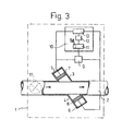
- Figure 3 illustrates a flow meter according to the present invention.
- Figure 4 shows a logic flow diagram of an exemplary mode of operating the flow meter according to the present invention.
- To better understand the present invention a known flow meter will first be described. Considering Figure 1, a
flow meter 1 comprises atube 2 through which a fluid can flow, for example in the direction of the arrows. Branches 3,4 are formed with fluidtight ends tube 2 and apiezoelectric transceiver transceiver other transceiver piezoelectric crystals transceiver transceivers transceiver 7 themeans 10 is switched to receive electrical signals only from thetransceiver 8, and vice versa. - Further description of the operation of the
flow meter 1 will be, for simplicity, made for a state where thetransceiver 7 is set to act as a transmitter and thetransceiver 8 is set to act as a receiver. - The pulse generator 9 supplies a single electrical pulse 14, shown generally by the inset of Figure 2, to the
piezoelectric transmitter 7 and provides a signal to themicroprocessor 11 of the timing means 10 to begin counting pulses from its internal clock. This electrical pulse 14 causes thetransmitter 7 to output awave train 15 which has zero amplitude crossings at P1-5, as shown in Figure 2. Thiswave train 15 passes through the fluid intube 2, at an angle to the direction of fluid flow, and is received at thepiezoelectric receiver 8 where it causes to be generated anelectrical wave train 15 with analogous voltage amplitude variations. This electrical signal is input to the timing means 10. - The timing means 10 also comprises circuitry 12, well known in the art, to detect zero voltage point crossings P1-5 and is configured to always determine the same zero voltage point crossing (for example P3) associated with the electrical pulse 14. On detecting this single zero point crossing a signal is transmitted to the
processor 11 which interrupts the clock pulse count. From a knowledge of the internal clock frequency of theprocessor 11 and the number of counted clock pulses between the generation and receipt of the ultrasonic signal theprocessor 11 can be programmed to calculate the transit time of the ultrasonic pulses. When fluid flows through thetube 2 in the direction shown in Figure 1 then with thetransceiver 7 acting as a transmitter and thetransceiver 8 acting as a receiver the downstream transit time Td will be determined by the timing means 10. - When the roles of the
transceivers processor 11 of the timing means 10 is further programmed to determine the fluid flow rate from Tu and Td and by using an equation well known to those versed in the physics of sound propagation as exemplified in US 5,247,826 and which may be expressed as:
- Where V is the bulk flow rate and K is a constant dependent on, inter alia, physical dimensions of the
flow meter 1 and which may be calculated or determined experimentally without undue effort. - Clearly, each electrical pulse 14 provides a received
signal 15 having a number of zero voltage crossing points P1-5. While it is intended to use only a single crossing point, for example P3, for each electrical pulse any of the crossing points P1-5 could be registered which would lead to errors in the determination of the transit time values Td and Tu and hence errors in the calculated flow rate can result. - In an attempt to remove this problem it is known to include in the
flow meter 1discriminator circuitry 13, for example at the input stage of the timing means 10, to prevent registering any crossing point but, for example, P3. Referring to Figure 2, thecircuitry 13 operates generally by looking for a zero point crossing in which thesignal 15 goes from negative to positive (or positive to negative) but only after thesignal 15 has fallen below (above) a preset threshold voltage V. In this way all but the crossing P3 can be discriminated against. Unfortunately measurement errors may still occur. For example if the threshold voltage is set too low (V') it may be possible to register one of several crossing points P2,3. Even if the voltage is set to a correct level, like V'' variations 15' in amplitude of thesignal 15, for example caused by noise or time dependent changes in the operational characteristics of thetransceivers - A
flow meter 1 according to the present invention is shown in Figure 3 and, being substantially similar to that of the known flow meter of Figure 1, is shown with common components having the same numbering as Figure 1. Upstream and downstream transit times, Tu and Td, respectively are determined as previously described and input into themicroprocessor 11 of the timing means 10. Different to the previously described known flow meter, anerror signal indicator 16 is included within the timing means 10 as part of the programmedmicroprocessor 11 which now operates according to the logic flow chart shown in Figure 4. - In use the
error signal indicator 16 makes the determination of a false transit time reading based on the summation of Tu and Td, Tsum. The microprocessor holds in memory a control value, Tc, which is a summed transit time value formed at zero (or low flow producing laminar flow) flow. This can be obtained at start up before fluid flows through themeter 1, or may be obtained when a flow control valve 17 (here shown as part of themeter 1 but which could be in the fluid system outside the flow meter 1) is closed to prevent fluid flowing in themeter 1 or may be obtained during periods when it is known that no fluid will be flowing through themeter 1. This last option may be preferred, for example when themeter 1 is used in breathing assist systems, such as in the expiration or inspiration sides of known ventilator systems, where by the very nature of the breathing process there will be periods when no fluid flows in one or other of the sides. Additionally, the control value Tc may be updated from new summations made at the zero flow condition or from measured values of Tsum obtained when theerror signal indicator 16 indicates that accurate transit time values were collected. - The
flow meter 1 operates in a manner previously described in connection with Figure 1 to obtain instantaneous values of Tu and Td. Theerror signal indicator 16 forms a value of Tsum using these instantaneous values and compares it with the control value Tc to determine the absolute value of Tc - Tsum. If this absolute value is greater than a preset threshold value Tt, which may be set at zero, then an error signal is generated by theerror signal indicator 16 of theprocessor 11. This signal may then be used in ways obvious to those skilled in the art, for example to inhibit a flow rate reading from being made or for varying operating parameters of the device to which the flow meter is connected to adjust the flow rate or for initiation correction algorithms within the flow meter to generate an estimated flow value, perhaps based on trends in the flow rate from previously calculate "good" flow rate measurements. If no error signal is generated theprocessor 11 then calculates the flow rate using equation (1). A sensible representation of this flow rate can then made, for example as an output on a computer screen or a dial. - It will be appreciated by those skilled in the art that flow meter according to the present invention as described above with the aid of Figure 4 could easily be modified to make error determinations based on the difference Tdiff between Tu and Td. In this case Tc would be, for example, Td-Tu and the
error signal generator 16 would operate to determine whether |Tc-Tdiff| exceeds a set amount.
Claims (9)
- An acoustic fluid flow meter comprising timing means (10) for determining downstream (Td) and upstream (Tu) transit time values of acoustic pulses transmitted between acoustic signal generators (7,8) and receivers (8,7) with and against the direction of fluid flow characterised in that there is additionally provided an error signal indicator (16) arranged to receive the determined transit time values (Td,Tu) and to output an error signal indicative of a false flow reading if the sum (Tsum) or the difference (Tdiff) of the downstream and upstream transit time values differs from a corresponding control value (Tc) by a predetermined amount.
- A fluid flow meter as claimed in claim 1 characterised in that the error signal indicator (16) is adapted to output the error signal dependent on the sum (Tsum) of the upstream (Tu) and downstream (Td) transit time values differing from the corresponding control value (Tc).
- A fluid flow meter as claimed in claim 2 characterised in that the corresponding control value (Tc) is formed from the sum of the transit time values determined during substantially laminar flow conditions.
- A fluid flow meter as claimed in claim 3 characterised in that the control value (Tc) is obtained when the flow rate is substantially zero.
- A fluid flow meter as claimed in claim 1 characterised in that the error signal indicator (16) is adapted to operate at a known flow rate and to output the error signal dependent on the difference (Tdiff) between the downstream (Td) and upstream (Tu) transit time values exceeding the corresponding control value.
- A fluid flow meter as claimed in claim 5 characterised in that the error signal indicator is adapted to operate at zero flow rate.
- A fluid flow meter as claimed in any preceding claim characterised in that there is further provided a valve (17) adapted to control the fluid flow past the acoustic signal generators (7,8) and receivers (8,7).
- A fluid flow meter as claimed in any preceding claim characterised in that the corresponding control value (Tc) is periodically updated using determined transit time values (Tu,Td).
- A fluid flow system comprising a conduit through which fluid can flow and a flow meter disposed to measure fluid flow through the conduit characterised in that the fluid flow meter comprises a meter (1) as claimed in any preceding claim.
Applications Claiming Priority (2)
| Application Number | Priority Date | Filing Date | Title |
|---|---|---|---|
| SE9800074A SE9800074D0 (en) | 1998-01-15 | 1998-01-15 | Acoustic flow meter |
| SE9800074 | 1998-01-15 |
Publications (3)
| Publication Number | Publication Date |
|---|---|
| EP0932029A2 EP0932029A2 (en) | 1999-07-28 |
| EP0932029A3 EP0932029A3 (en) | 1999-09-15 |
| EP0932029B1 true EP0932029B1 (en) | 2006-09-27 |
Family
ID=20409859
Family Applications (1)
| Application Number | Title | Priority Date | Filing Date |
|---|---|---|---|
| EP98121533A Expired - Lifetime EP0932029B1 (en) | 1998-01-15 | 1998-11-17 | Acoustic flow meter |
Country Status (5)
| Country | Link |
|---|---|
| US (1) | US6098467A (en) |
| EP (1) | EP0932029B1 (en) |
| JP (1) | JPH11271119A (en) |
| DE (1) | DE69836002T2 (en) |
| SE (1) | SE9800074D0 (en) |
Families Citing this family (12)
| Publication number | Priority date | Publication date | Assignee | Title |
|---|---|---|---|---|
| US7152490B1 (en) | 2005-08-15 | 2006-12-26 | Daniel Measurement And Control, Inc. | Methods for determining transducer delay time and transducer separation in ultrasonic flow meters |
| US7681460B2 (en) * | 2007-04-20 | 2010-03-23 | Gilbarco Inc. | System and method for detecting pressure variations in fuel dispensers to more accurately measure fuel delivered |
| JP2009058444A (en) * | 2007-08-31 | 2009-03-19 | Institute Of National Colleges Of Technology Japan | Flowmeter for artificial respirator |
| US7725271B2 (en) * | 2007-11-13 | 2010-05-25 | Gilbarco Inc. | Nozzle snap flow compensation |
| US8042376B2 (en) * | 2008-06-02 | 2011-10-25 | Gilbarco Inc. | Fuel dispenser utilizing pressure sensor for theft detection |
| US8494932B2 (en) * | 2011-03-18 | 2013-07-23 | International Business Machines Corporation | Fluid flow measurement system |
| DE102012112516A1 (en) * | 2012-12-18 | 2014-06-18 | Endress + Hauser Flowtec Ag | Method for verifying the reliability of measured data measured by an ultrasonic flow measurement according to the transit time difference method and ultrasonic flowmeter |
| WO2016025859A2 (en) | 2014-08-14 | 2016-02-18 | Soneter, Inc. | Devices and system for channeling and automatic monitoring of fluid flow in fluid distribution systems |
| EP3730905A1 (en) | 2014-08-14 | 2020-10-28 | Reliance Worldwide Corporation | Methods and apparatus for fluid flow monitoring and leak detection |
| FR3030726A1 (en) | 2014-12-19 | 2016-06-24 | Gdf Suez | NON-INTRUSIVE POWER SOURCE SENSOR AUTONOMOUS IN ENERGY AND METHOD FOR CONVERTING THERMAL ENERGY IN ELECTRIC ENERGY TO A FLUID TRANSPORT NETWORK USING SUCH A SENSOR |
| US9714855B2 (en) | 2015-01-26 | 2017-07-25 | Arad Ltd. | Ultrasonic water meter |
| CN110383014B (en) * | 2017-03-07 | 2022-01-04 | Abb瑞士股份有限公司 | Apparatus and method for measuring flow velocity of fluid in pipe |
Family Cites Families (11)
| Publication number | Priority date | Publication date | Assignee | Title |
|---|---|---|---|---|
| US3818757A (en) * | 1972-05-05 | 1974-06-25 | Saratoga Sys Inc | Dual path ultrasonic fluid flow metering system and method |
| US3918304A (en) * | 1973-11-23 | 1975-11-11 | Westinghouse Electric Corp | Flowmeter computer |
| JPS5829854B2 (en) * | 1977-07-26 | 1983-06-25 | 富士電機株式会社 | Ultrasonic measuring device |
| US4271708A (en) * | 1978-05-16 | 1981-06-09 | Fuji Electric Co., Ltd. | Ultrasonic measuring apparatus |
| JPS5827449B2 (en) * | 1978-08-09 | 1983-06-09 | 富士電機株式会社 | Ultrasonic propagation time detection circuit device |
| US4345479A (en) * | 1981-01-13 | 1982-08-24 | The Perkin-Elmer Corporation | Flowmeter system with synchronous clock for generation of timing signals |
| JPS59195126A (en) * | 1983-04-21 | 1984-11-06 | Yokogawa Hokushin Electric Corp | Ultrasonic flow meter |
| US4633719A (en) * | 1985-03-27 | 1987-01-06 | Badger Meter, Inc. | Digital flow meter circuit and method for measuring flow |
| US5247826B1 (en) * | 1992-11-12 | 1995-07-18 | Devilbiss Health Care Inc | Gas concentration and/or flow sensor |
| DE4318690A1 (en) * | 1993-06-04 | 1995-01-05 | Ndd Medizintechnik Gmbh | Method for measuring the molar mass of gases or gas mixtures and device for carrying out this method |
| US5463906A (en) * | 1994-01-24 | 1995-11-07 | Triton Technology, Inc. | Interchangeable disposable acoustic for use with an ultrasonic flowmeter, particularly during extracorporeal measurement of blood flow |
-
1998
- 1998-01-15 SE SE9800074A patent/SE9800074D0/en unknown
- 1998-11-17 EP EP98121533A patent/EP0932029B1/en not_active Expired - Lifetime
- 1998-11-17 DE DE69836002T patent/DE69836002T2/en not_active Expired - Lifetime
- 1998-12-15 US US09/210,832 patent/US6098467A/en not_active Expired - Lifetime
-
1999
- 1999-01-14 JP JP11007934A patent/JPH11271119A/en active Pending
Also Published As
| Publication number | Publication date |
|---|---|
| EP0932029A2 (en) | 1999-07-28 |
| DE69836002D1 (en) | 2006-11-09 |
| JPH11271119A (en) | 1999-10-05 |
| DE69836002T2 (en) | 2007-05-16 |
| SE9800074D0 (en) | 1998-01-15 |
| US6098467A (en) | 2000-08-08 |
| EP0932029A3 (en) | 1999-09-15 |
Similar Documents
| Publication | Publication Date | Title |
|---|---|---|
| EP0932029B1 (en) | Acoustic flow meter | |
| US8700344B2 (en) | Ultrasonic flow meter | |
| TWI386629B (en) | Flow measurement device | |
| US7073395B2 (en) | Ultrasonic flowmeter and ultrasonic flow rate measuring method | |
| JPH06148003A (en) | Ultrasonic temperature measuring equipment | |
| JP3562712B2 (en) | Flow measurement device | |
| EP0981201B1 (en) | Zero crossing detector and method of determining a zero crossing point | |
| JP4673950B2 (en) | Abnormality diagnosis device for ultrasonic gas flow rate measuring unit and ultrasonic gas meter equipped with the abnormality diagnosis device | |
| EP3321644A1 (en) | Fluid flow monitoring unit | |
| EP1231456B1 (en) | Arrangement for and method of acoustic determination of fluid temperature | |
| JP4760115B2 (en) | Fluid flow measuring device | |
| JP4792653B2 (en) | Flowmeter | |
| JP4082246B2 (en) | Flowmeter | |
| JP6405520B2 (en) | Ultrasonic flow meter | |
| CN114878018A (en) | Method for calibrating an apparatus for ultrasonic measurement, method and apparatus for measuring the temperature of a medium | |
| JP3443658B2 (en) | Flow measurement device | |
| JP2000074719A (en) | Estimation type flowmeter | |
| JP4813649B2 (en) | Gas shut-off device | |
| JP2004085421A (en) | Ultrasonic flow meter | |
| JP4623488B2 (en) | Fluid flow measuring device | |
| JP4163887B2 (en) | Flowmeter | |
| JP4390350B2 (en) | Gas meter | |
| JPH0336889Y2 (en) | ||
| JP5229349B2 (en) | Fluid flow measuring device | |
| JPS5870132A (en) | Ultrasonic flowmeter |
Legal Events
| Date | Code | Title | Description |
|---|---|---|---|
| PUAI | Public reference made under article 153(3) epc to a published international application that has entered the european phase |
Free format text: ORIGINAL CODE: 0009012 |
|
| AK | Designated contracting states |
Kind code of ref document: A2 Designated state(s): DE FR SE |
|
| AX | Request for extension of the european patent |
Free format text: AL;LT;LV;MK;RO;SI |
|
| PUAL | Search report despatched |
Free format text: ORIGINAL CODE: 0009013 |
|
| AK | Designated contracting states |
Kind code of ref document: A3 Designated state(s): AT BE CH CY DE DK ES FI FR GB GR IE IT LI LU MC NL PT SE |
|
| AX | Request for extension of the european patent |
Free format text: AL;LT;LV;MK;RO;SI |
|
| 17P | Request for examination filed |
Effective date: 20000121 |
|
| AKX | Designation fees paid |
Free format text: DE FR SE |
|
| RAP1 | Party data changed (applicant data changed or rights of an application transferred) |
Owner name: MAQUET CRITICAL CARE AB |
|
| GRAP | Despatch of communication of intention to grant a patent |
Free format text: ORIGINAL CODE: EPIDOSNIGR1 |
|
| RIN1 | Information on inventor provided before grant (corrected) |
Inventor name: WALLEN, LARS |
|
| GRAS | Grant fee paid |
Free format text: ORIGINAL CODE: EPIDOSNIGR3 |
|
| GRAA | (expected) grant |
Free format text: ORIGINAL CODE: 0009210 |
|
| AK | Designated contracting states |
Kind code of ref document: B1 Designated state(s): DE FR SE |
|
| REF | Corresponds to: |
Ref document number: 69836002 Country of ref document: DE Date of ref document: 20061109 Kind code of ref document: P |
|
| PG25 | Lapsed in a contracting state [announced via postgrant information from national office to epo] |
Ref country code: SE Free format text: LAPSE BECAUSE OF FAILURE TO SUBMIT A TRANSLATION OF THE DESCRIPTION OR TO PAY THE FEE WITHIN THE PRESCRIBED TIME-LIMIT Effective date: 20061227 |
|
| ET | Fr: translation filed | ||
| PLBE | No opposition filed within time limit |
Free format text: ORIGINAL CODE: 0009261 |
|
| STAA | Information on the status of an ep patent application or granted ep patent |
Free format text: STATUS: NO OPPOSITION FILED WITHIN TIME LIMIT |
|
| 26N | No opposition filed |
Effective date: 20070628 |
|
| REG | Reference to a national code |
Ref country code: DE Ref legal event code: R082 Ref document number: 69836002 Country of ref document: DE Representative=s name: SCHAUMBURG UND PARTNER PATENTANWAELTE MBB, DE Ref country code: DE Ref legal event code: R082 Ref document number: 69836002 Country of ref document: DE Representative=s name: SCHAUMBURG & PARTNER PATENTANWAELTE MBB, DE Ref country code: DE Ref legal event code: R082 Ref document number: 69836002 Country of ref document: DE Representative=s name: SCHAUMBURG & PARTNER PATENTANWAELTE GBR, DE |
|
| REG | Reference to a national code |
Ref country code: FR Ref legal event code: PLFP Year of fee payment: 18 |
|
| PGFP | Annual fee paid to national office [announced via postgrant information from national office to epo] |
Ref country code: DE Payment date: 20151110 Year of fee payment: 18 |
|
| PGFP | Annual fee paid to national office [announced via postgrant information from national office to epo] |
Ref country code: FR Payment date: 20151008 Year of fee payment: 18 |
|
| REG | Reference to a national code |
Ref country code: DE Ref legal event code: R119 Ref document number: 69836002 Country of ref document: DE |
|
| REG | Reference to a national code |
Ref country code: FR Ref legal event code: ST Effective date: 20170731 |
|
| PG25 | Lapsed in a contracting state [announced via postgrant information from national office to epo] |
Ref country code: FR Free format text: LAPSE BECAUSE OF NON-PAYMENT OF DUE FEES Effective date: 20161130 |
|
| PG25 | Lapsed in a contracting state [announced via postgrant information from national office to epo] |
Ref country code: DE Free format text: LAPSE BECAUSE OF NON-PAYMENT OF DUE FEES Effective date: 20170601 |