EP0933731B1 - Electronic transaction system - Google Patents
Electronic transaction system Download PDFInfo
- Publication number
- EP0933731B1 EP0933731B1 EP97940371A EP97940371A EP0933731B1 EP 0933731 B1 EP0933731 B1 EP 0933731B1 EP 97940371 A EP97940371 A EP 97940371A EP 97940371 A EP97940371 A EP 97940371A EP 0933731 B1 EP0933731 B1 EP 0933731B1
- Authority
- EP
- European Patent Office
- Prior art keywords
- card
- customer
- atm
- transaction
- electronic money
- Prior art date
- Legal status (The legal status is an assumption and is not a legal conclusion. Google has not performed a legal analysis and makes no representation as to the accuracy of the status listed.)
- Expired - Lifetime
Links
- 101100492805 Caenorhabditis elegans atm-1 gene Proteins 0.000 description 82
- 238000012545 processing Methods 0.000 description 35
- 238000003780 insertion Methods 0.000 description 26
- 230000037431 insertion Effects 0.000 description 26
- 238000000034 method Methods 0.000 description 25
- 230000009118 appropriate response Effects 0.000 description 10
- 238000013459 approach Methods 0.000 description 7
- 238000012546 transfer Methods 0.000 description 7
- 238000004364 calculation method Methods 0.000 description 6
- 238000012790 confirmation Methods 0.000 description 6
- 230000008569 process Effects 0.000 description 6
- 238000004891 communication Methods 0.000 description 5
- 238000005516 engineering process Methods 0.000 description 4
- 230000015654 memory Effects 0.000 description 4
- 230000004044 response Effects 0.000 description 4
- 230000008520 organization Effects 0.000 description 3
- 230000008859 change Effects 0.000 description 2
- 238000001514 detection method Methods 0.000 description 2
- 230000000694 effects Effects 0.000 description 2
- 238000009434 installation Methods 0.000 description 2
- 230000004913 activation Effects 0.000 description 1
- 238000012550 audit Methods 0.000 description 1
- 238000010276 construction Methods 0.000 description 1
- 238000000151 deposition Methods 0.000 description 1
- 238000010586 diagram Methods 0.000 description 1
- 230000006870 function Effects 0.000 description 1
- 238000012986 modification Methods 0.000 description 1
- 230000004048 modification Effects 0.000 description 1
- 238000012544 monitoring process Methods 0.000 description 1
- 238000012360 testing method Methods 0.000 description 1
- 230000007704 transition Effects 0.000 description 1
Images


Classifications
-
- G—PHYSICS
- G07—CHECKING-DEVICES
- G07D—HANDLING OF COINS OR VALUABLE PAPERS, e.g. TESTING, SORTING BY DENOMINATIONS, COUNTING, DISPENSING, CHANGING OR DEPOSITING
- G07D9/00—Counting coins; Handling of coins not provided for in the other groups of this subclass
-
- G—PHYSICS
- G07—CHECKING-DEVICES
- G07F—COIN-FREED OR LIKE APPARATUS
- G07F7/00—Mechanisms actuated by objects other than coins to free or to actuate vending, hiring, coin or paper currency dispensing or refunding apparatus
- G07F7/08—Mechanisms actuated by objects other than coins to free or to actuate vending, hiring, coin or paper currency dispensing or refunding apparatus by coded identity card or credit card or other personal identification means
- G07F7/0866—Mechanisms actuated by objects other than coins to free or to actuate vending, hiring, coin or paper currency dispensing or refunding apparatus by coded identity card or credit card or other personal identification means by active credit-cards adapted therefor
-
- G—PHYSICS
- G06—COMPUTING; CALCULATING OR COUNTING
- G06Q—INFORMATION AND COMMUNICATION TECHNOLOGY [ICT] SPECIALLY ADAPTED FOR ADMINISTRATIVE, COMMERCIAL, FINANCIAL, MANAGERIAL OR SUPERVISORY PURPOSES; SYSTEMS OR METHODS SPECIALLY ADAPTED FOR ADMINISTRATIVE, COMMERCIAL, FINANCIAL, MANAGERIAL OR SUPERVISORY PURPOSES, NOT OTHERWISE PROVIDED FOR
- G06Q20/00—Payment architectures, schemes or protocols
- G06Q20/08—Payment architectures
- G06Q20/10—Payment architectures specially adapted for electronic funds transfer [EFT] systems; specially adapted for home banking systems
- G06Q20/105—Payment architectures specially adapted for electronic funds transfer [EFT] systems; specially adapted for home banking systems involving programming of a portable memory device, e.g. IC cards, "electronic purses"
-
- G—PHYSICS
- G06—COMPUTING; CALCULATING OR COUNTING
- G06Q—INFORMATION AND COMMUNICATION TECHNOLOGY [ICT] SPECIALLY ADAPTED FOR ADMINISTRATIVE, COMMERCIAL, FINANCIAL, MANAGERIAL OR SUPERVISORY PURPOSES; SYSTEMS OR METHODS SPECIALLY ADAPTED FOR ADMINISTRATIVE, COMMERCIAL, FINANCIAL, MANAGERIAL OR SUPERVISORY PURPOSES, NOT OTHERWISE PROVIDED FOR
- G06Q20/00—Payment architectures, schemes or protocols
- G06Q20/30—Payment architectures, schemes or protocols characterised by the use of specific devices or networks
- G06Q20/36—Payment architectures, schemes or protocols characterised by the use of specific devices or networks using electronic wallets or electronic money safes
- G06Q20/363—Payment architectures, schemes or protocols characterised by the use of specific devices or networks using electronic wallets or electronic money safes with the personal data of a user
Definitions
- the present invention relates to an electronic transaction system for depositing currency to a financial institution such as a bank, storing a value corresponding to this currency as money information (electronic money) in an card (IC card) mounted with an integrated circuit and settling the cost by withdrawing from electronic money stored on the IC card when paying at the time of a business transaction such as the purchase of goods.
- a financial institution such as a bank
- money information electronic money
- IC card mounted with an integrated circuit
- a number of methods of settling costs using electronic money exist, such as prepaid (advance payment), debit (immediate payment) and credit (deferred payment).
- An example of a method of settling costs is EP 0 668 579 A2. It discloses systems and methods for providing secure electronic financial transactions characterized in that money is electronically stored on a plurality of smart cards.
- a plurality of smart cards are each equipped with an electronic security wall having a closed state and an open state. In the closed state, the smart card is disabled from participating in financial transactions, and in the open state, the smart card may participate in financial transactions.
- a security key smart card is equipped with a first security key for changing the state of the electronic security wall from the open state to the closed state, and a second security key for changing the state of the electronic security wall from the closed state to the open state.
- Financial transactions include, for example, electronically transferring money between a bank center and a smart card; electronically transferring money between the first and second smart cards; checking the amount of money stored on a smart card; and adding interest to the amount of money stored on the smart card.
- This technology is characterized by the point that charge settlement is then complete in the case of a business transaction.
- This technology means that the former case where a vender would have to take transaction records to a financial institution to have the transaction records put into cash form is no longer the case.
- This technology has reduced the cash handling costs involved in the calculating of cash and change at vendors and financial institutions and eliminated the accompanying office processing.
- a customer card When a customer card is replenished with electronic money at a branch of a financial institution, the customer utilizes an automatic teller machine capable of performing electronic money replenishment transactions, cash is put into the automatic teller machine so that the cash is converted to electronic money and this then replenishes a customer card.
- a connection can be made using the automatic teller machine with the host computer of the financial institution managing the customers account and the customer can replenish the customer card with electronic money from their own account to a value corresponding to a prescribed amount.
- the customer When the customer replenishes the customer card with electronic money at their own home, the customer connects with the host computer of the financial institution managing their personal account via a communications line etc. using a household terminal capable of performing electronic money replenishing transactions and replenishes the customer card inserted into the household terminal with a value corresponding to a prescribed amount to be withdrawn from the customers own account in the form of electronic money. It is therefore necessary at this time for the customer to prepare a number of household terminals for each of the cost settlement conditions which requires substantial installation investment. Alternatively, it is necessary to prepare a customer card issued by the issuing body that coincides with the charge settlement conditions set at the household terminal. Either approach is extremely troublesome for the customer. Because of these reasons, customers have not been able to utilize the electronic transaction systems in a sufficient manner and financial institutions have not been able to effectively utilize automatic teller machines that have been maintained with substantial investment in installations.
- the object of the present invention is to provide an electronic transaction system capable of executing transaction processes of different settlement conditions using a single terminal.
- a plurality of IC cards for use on the financial institution side corresponding to pre-decided settlement conditions are provided at each terminal.
- FIG. 1 is a view illustrating the concept of a transaction of the present invention
- FIG. 2 is a block view of control of the automatic transaction device of the present invention
- FIG. 3 is a view illustrating the outline of a card processor of the present invention.
- FIG. 4 is a view illustrating the IC card of the present invention.
- FIG. 5 is a conceptual view of the storage data of the IC card A of the present invention.
- FIG. 6 is a conceptual view of the storage data of the IC card B of the present invention.
- FIG. 7 is a conceptual view of the storage data of the IC card C of the present invention.
- FIG. 8 is a system view of the electronic transaction system of the present invention.
- FIG. 9 is a flowchart of an electronic settlement of the present invention.
- FIG. 10 is a flowchart of an electronic settlement of the present invention.
- FIG. 11 is a flowchart of an electronic settlement of the present invention.
- FIG. 12 is a view illustrating an example customer guidance screen display of the present invention.
- FIG. 13 is a view illustrating an example customer guidance screen display of the present invention.
- FIG. 14 is a flowchart of the electronic settlement of the present invention.
- a plurality of ATM cards for carrying out transaction processing of pre-decided transaction conditions for electronic money of different issuers or for different types of electronic money of the same issuer are housed at an automatic teller machine, control software for controlling the plurality of ATM cards is stored and a plurality of transaction processes of different settlement types can be obtained.
- This system is capable of carrying out transaction processing using electronic money of different issuing bodies or different types of electronic money of the same issuer.
- the automatic teller machine of the first aspect of the present invention reads information specifying settlement conditions from an inserted customer card, activates control software coinciding with the settlement conditions using the read information and carries out transactions between the ATM card stored in the automatic teller machine and the customer card.
- This system reads information specifying the settlement conditions from the customer card and specifies the settlement conditions based on this information.
- the automatic teller machine of the first aspect of the present invention activates control software in a pre-decided settlement condition order when information specifying the settlement conditions is read from the inserted customer card and settlement conditions cannot be specified from the read information.
- This system tests transaction processes in order using pre-decided settlement conditions when information specifying settlement conditions cannot be read from the customer card.
- FIG. 1 is a view illustrating the concept of a transaction of the present invention
- FIG. 2 is a block diagram of control of an ATM used in the electronic transaction system of the present invention
- FIG. 3 is a view illustrating an outline of a guard processor of the present invention.
- This specific example shows a transaction system capable of executing transaction processing with three types of different settlement conditions using just one terminal.
- numeral 1 represents an automatic teller machine (hereinafter referred to as "ATM") installed in a branch of a financial institution, a supermarket, convenience store or gasoline stand etc.
- Numeral 2 represents a communication line.
- Numeral 3 represents a host computer constituting an upper order device for the AIM 1 connected to the ATM 1 via the communication line 2.
- Numeral 4 represents a storage device connected to and managed by the host computer 3.
- Numeral 4a represents a customer account file 4a stored in the storage device 4.
- the customer account file 4a stores the address, name, age, occupation, account number, pin number and balance information etc. for the account holder.
- the customer account file 4a is updated with the newest information when updating of the deposit balance information is designated by the host computer 3 every time a deposit or withdrawal transaction is carried out.
- Numeral 5 represents a card handling unit for reading information stored on a card for customer use (hereinafter referred to as a customer card) and writing information.
- Numeral 5a represents a card insertion/return opening 5a.
- the card insertion/return opening 5a is provided at the front of the ATM 1 and is connected by a conveyance path with the card handling unit 5 provided within the ATM 1.
- the customer card is conveyed to the card handling unit 5 by the conveyance path wherein prescribed transaction processing is executed.
- the customer card is then conveyed to the card insertion/return opening 5a from the card handling unit 5 by the conveyance path and dispatched to outside of the ATM 1 from the card insertion/return opening 5a so as to be returned to the customer.
- Numeral 5b represents a magnetic reader.
- Numeral 5c represents an embossed character reader 5c for reading information recorded in a display area (to be described later) of the customer card.
- Numeral 5d represents an IC card reader electrically connected with the IC (Integrated Circuit) of the customer card, for reading information stored in the IC and writing information.
- Numeral 6 is a temporary card holding section for temporarily holding cards inserted within the ATM 1 from the card insertion/return opening 5a and is provided in a sideways direction of the embossed card reader 5c so as to be conveyed so as to diverge from a conveyance path linking the card insertion/return opening 5a and the IC card reader/writer 5d by a conveyance means (5a).
- the customer card is conveyed to the temporary card holding section 6 from a conveyance path linking the card insertion/return opening 5a and the IC card reader 5d by a conveyance means (not shown).
- the conveyance means is constructed from a plurality of pairs of conveyance rollers and driver motors etc. constructed so as to be capable of rotating while sandwiching the customer card.
- This conveyance means and various sensors for conveyance control provided at the periphery of the conveyance means bear no direct relationship to the present invention and are therefore omitted from the drawings.
- Numeral 7 represents a receipt handling unit.
- the receipt handling unit 7 prints transaction details on receipts 8 issued to the customer for every transaction and performs issuance processing.
- the conveyance path for conveying the receipt 8 is provided so as to merge in the vicinity of the conveyance path for conveying the customer card and the card insertion/return opening 5a.
- These conveyance paths are provided with card sensing means (not shown) in the vicinity of the card insertion/return opening 5a.
- the card sensing means senses the insertion of a customer card as well as sensing returned customer cards and discharge of issued receipts.
- Numeral 9 represents a customer interface.
- the customer operating unit 9 comprises, for example, a touch panel.
- the customer operating unit 9 displays screens such as "IC card transaction guidance” or "withdrawals” which constitute one type of withdrawal processing and guides the customer to select the type of processing. If, at this time, the customer lightly touches (presses), for example, the part of the display for "withdrawals", the ATM 1 executes a transaction to replenish the customer card with electronic money.
- Numeral 10 represents an audio guidance unit provided on the front of the ATM 1 for giving operation guidance using speech.
- the audio guidance unit 10 comprises a speaker 10a and a microphone 10b.
- Numeral 11 represents a guidance display and numeral 11a represents a display provided at the front of the ATM 1.
- the guidance display 11 is for displaying possible transactions and operation guidance or can display information such as information peculiar to the local area when in a wait state at the display 11a.
- Numerals 12a, 12b and 12c represent first, second and third card readers provided within the ATM 1.
- IC cards for financial institution use hereinafter referred to as "ATM cards" 200a, 200b and 200c to be described later are installed at the card reader/writers 12a, 12b and 12c, respectively.
- ATM cards IC cards for financial institution use
- One of these card reader/writers is selected and driven for every transaction process in response to the type of customer card inserted via the card insertion/return opening 5a or the transaction settlement conditions.
- the driven card reader/writer is itself electrically connected to an ATM card, with information being exchanged based on prescribed control software.
- Numeral 13 is an internal operation part.
- the internal operation part 13 is constructed from, for example, a touch panel.
- the internal operation part 13 displays screens such as, for example, "procedure for installing ATM card to the card reader/writer".
- the clerk then installs ATM cards 200a, 200b and 200c at the card reader/writers 12a, 12b and 12c based on this display. Further, the internal operation part 13 is inputted with a code for releasing a prescribed door for the clerk and information for setting up the ATM cards, etc.
- Numeral 14 represents a storage part provided within the ATM 1 consisting of ROM (Read Only Memory) and RAM (Random Access Memory) or a floppy disc etc.
- the storage part 14 has storage areas 14a, 14b and 14c. Programs for carrying out various control and control software for driving the first to third card readers 12a, 12b and 12c are stored in these storage areas.
- Numeral 15 represents an interface (hereinafter referred to as "I/F") for connecting the ATM 1 with the host computer 3.
- I/F an interface
- Numeral 16 represents an proximity detector located at the front of the ATM 1 for detecting when a customer approaches the ATM 1. When a customer approaches the ATM 1, this is detected by the proximity detector 16 and a transition is made from a wait state to a transaction possible state. When the customer finishes the transaction and moves away from the ATM 1, this is also detected by the approach detector 16 and the higher order device is notified.
- Numeral 17 represents a main controller for controlling each of the above parts.
- Numeral 18 represents a power supply for supplying electrical power to each of the above parts.
- IC cards Electronic money cards
- these are described separately from each other.
- the theme of the present invention is charge settlement using electronic money, a description of the configuration of magnetic cards 19, that bear little relation to charge settlement using electronic money, is omitted.
- FIG. 4 is a view illustrating an IC card.
- numeral 20 represents an IC card.
- the size, physical characteristics, electrical characteristics and communications protocol of the IC card 20 all conform to international standards.
- Numeral 201 represents a magnetic stripe. This magnetic stripe 201 is magnetically recorded with data peculiar to a particular customer such as a financial institution code, customer name, and account number etc. as well as a code that indicates that this IC card 20 has an IC (integrated circuit).
- Numeral 202 is an IC (integrated circuit) chip. This IC chip 202 is embedded at a predetermined position of the card material, with electrical signals being exchanged with the IC card reader 5a via terminals exposed at the surface of the card.
- the IC chip 202 has a ROM (Read Only Memory) written with a management program for carrying out transaction settlements, a RAM (Random Access Memory) for temporarily storing transaction contents and an EEPROM (Electrically Erasable and Programmable ROM) constituting a non-volatile memory for electrically erasing and re-writing storage information.
- the IC chip 202 also has storage circuit for storing various kinds of data (for example, encryption software and encryption key information, and financial institution codes and data peculiar to a particular customer, etc.) and a control circuit (MPU) for controlling reading and writing to each of the memories.
- Numeral 203 represents a display area.
- the display area 203 is printed with a code of a financial institution, a customer name and account number etc. and is embossed with embossed characters.
- FIG. 4 is "A01” taken as an issuing body number, "023” taken as a identifying number, "4567890” taken as an ID number and the customer name is taken as "OO smith”.
- IC cards 20 corresponding to the types A, B and C are then described as 20a, 20b and 20c, respectively are taken as type A, B and C, respectively, and classified for IC card 20a, 20b, and 20b respectively.
- the IC card 20 is stated as a typical example, when describing matters common to the IC cards 20a, 20b and 20c.
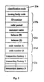
- FIG. 5 is a conceptual view of data stored in the IC card 20a.
- numeral 21a is a classification code showing that type A is taken as the settlement condition.
- Numeral 21b represents data for the issuing body code, ID number, valid period, and customer name. Data stored at 21a and 21b is partially the same as information stored at the magnetic stripe 201.
- Numeral 21c represents the electronic money balance held within the card.
- the balance 21c is recorded for each currency unit such as "yen” and “dollar” as shown in FIG. 5. This balance 21c is updated so as to be reduced when payment is carried out in a goods purchase transaction.
- Numeral 21d is a code number for identifying the customer.
- code number A and code number B are set. These code numbers can be arbitrarily set in response to the application.
- code number A can be set to be used by the customer themselves and code number B can be set to be used by a member of the customers family, etc.
- code number A can be set to be used for replenishment transactions and code number B can be set to be used for withdrawal transactions.
- Numeral 21e represents a transaction history of first to Nth transactions.
- the transaction history 21e is data showing date and time, product name and amount etc. when carrying out transactions for purchasing goods.
- At least the balance amount 21c and the transaction history 21e are stored in EEPROM capable of being updated. Reading and writing of this data to and from the EEPROM is controlled by the aforementioned control circuitry.
- the configuration is such that funds (electronic money) held in the IC card 20 are temporarily frozen by the aforementioned control circuitry.
- FIG. 6 is a conceptual view of data stored at the IC card 20b.
- This IC card 20b is for executing transaction processing of settlement conditions different to the settlement conditions of the IC card 20a. These different settlement conditions occur due to differences in methods or even when the method is the same, different approaches of each financial institution (banks, credit companies, and intermediaries etc.) that issues electronic money.
- numeral 22a represents an identification code showing that type B is taken as the settlement condition.
- Numeral 22b is data for the issuing body code, ID number and customer name.
- Numeral 22c represents a code number for identifying the customer.
- Numeral 22d represents valid period data.
- the construction is such that funds (electronic money) held within the IC card 20 are temporarily frozen by the aforementioned control circuitry in order to keep the electronic transaction system secure. This is to take into consideration the chance that the storage data within the IC chip 202 may be updated due to changes in the system etc.
- Numeral 22e represents a credit limit balance applied to the customer by the financial institution.
- the balance 22e is reduced so as to be updated.
- portions that are used are collected together and withdrawn from an account established at a financial institution etc. via a settlement network line.
- Numeral 22f represents transaction limit data indicating the limit to which transactions are possible in the case of mainly credit (deferred payment) transactions.
- Numeral 22g represents a transaction history for first to Nth transactions.
- the transaction history 22g is data showing the day and time, goods name and amount etc. when a product purchase transaction is carried out.
- At least the balance 22e and the transaction history 22g are stored in an EEPROM.
- FIG. 7 is a conceptual view of the data stored in the IC card 20c.
- This IC card 20c is for executing transaction processing for settlement conditions different to the settlement conditions of the IC cards 20a and 20b.
- numeral 23a represents an identification code indicating that type C is taken as the settlement condition.
- Numeral 23b represents data for the issuing body code, ID number, customer name and valid period (not shown) etc.
- Numeral 23c represents a code number for identifying the customer.
- Numeral 23d represents the electronic money balance stored within the card. This balance 23d is reduced so as to be updated when a payment operation due to a goods purchase transaction is carried out. With this purchase transaction, a prescribed amount is transferred beforehand from an account established at a financial institution etc. via the settlement network line so that cash is converted to electronic money.
- Numeral 23e represents a currency number.
- the balance is assumed to be stored as a currency type, with the currency number 23 then indicating a currency number for each type of money. For example, when it is assumed that one hundred thousand yen of electronic money is stored as eight ten thousand yen notes, two five thousand yen notes and ten one thousand yen notes, an alphanumeric number of approximately ten digits is added to each money type data as a currency number.
- Numeral 23f is for service points given for purchase amounts etc. every time goods are purchased at a shop etc., with these service points being set by the issuing body.
- Numeral 23g represents an individual information memo.
- the individual information memo is data for, for example, a driver's license or passport number, company employee certificate, residents card or public transport card.
- At least the balance 23d, currency number 23e, point 23f and individual information memo 23g are stored on EEPROM.
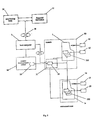
- FIG. 8 is a view of the system organization of the electronic transaction system of the present invention.
- Numeral 30 represents a branch of a financial institution, with an ATM 1 established within a store.
- Numeral 31 is a branch cash server for controlling other ATMs (not shown) and an ATM 1a within an unmanned shop 32 and for sending funds from a server card 33 when there are insufficient funds at an ATM card 200 installed in the ATMs 1 and 1a.
- Numeral 34 is a money management center for allotting separate funds to each branch and carrying out detailed audits of funds.
- the money management center also designates the transfer of funds from a center card 35 to a server card 33 within a branch 30.
- Numeral 36 represents a credit company connected to a host computer 3 via a settlement network line 38.
- Numeral 37 represents a financial institution such as a bank etc. configured so as to be capable of carrying out transactions, with electronic settlement using an IC card also being possible.
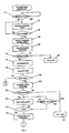
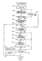
- FIG. 9, FIG. 10 and FIG. 11 are flowcharts showing the procedure for transferring funds from a customer deposit account to the IC card 20 as an example procedure for an electronic transaction.
- a procedure is shown where a customer uses the magnetic card 19 and the IC card 20 so as to access a customer deposit account stored in the host computer of a financial institution using the magnetic card 19 so as to transfer funds from the customer deposit account to the IC card 20.
- S indicates each operation step.
- FIG. 12 is a view illustrating an example display of a customer guidance screen of the present invention
- FIG. 13 is a further view illustrating an example display of a customer guidance screen of the present invention.
- the ATM detects this using a proximity detector 16 and a display of a customer operating unit 9 is changed over from a wait screen to a customer guidance screen (S1).
- the screen is changed over (S2), "please insert your IC card” is displayed as shown in FIG. 12 and a transaction selection is obtained.
- the ATM 1 then reads the magnetic information and discerns whether or not this is a card for which transactions are permitted (S6). At this time, the ATM 1 discerns whether the customer card is a magnetic card 19 or an IC card 20. Then ATM 1 then conveys the customer card further inside, reading of a display area 203 is carried out by the embossed character reader 5c (S7) and this information is temporarily stored in a storage part 14.
- the ATM 1 conveys the IC card 20 as far as a position from which information stored on the IC chip 202 is stored can be carried out and the IC card 20 is then temporarily halted (S8).
- the customer card is a magnetic card 19
- the ATM 1 is temporarily held in a temporary card holding section 6 and the customer is made to insert an IC card 20.
- the ATM 1 conveys the card in as far as the card insertion/return opening 5a, indication that a transaction is not possible is displayed at the customer operating unit 9 and withdrawal of the customer card is indicated (S9).
- the ATM displays "input card of account to be withdrawn from and input code number, or when a card is not used, press the confirm button please" at the customer guidance screen and the customer is invited to insert the magnetic card 19.
- the magnetic card 19 is then inserted via the card insertion/return opening 5a, it is detected (S10) and carried as far as the card handling unit 5, and the magnetic information stored on the magnetic stripe 191 is read (S11).
- S10 the magnetic card 19 is not inserted and the confirmation button is pressed is described in the following.
- the ATM 1 determines that the bank card can be handled on the basis of the read magnetic information (S12), read information such as the account number etc. of the magnetic card 19 is transmitted to the host computer 3 and a search for customer information within an customer account file 4a within a storage device 4 is commenced.
- a code number is then inputted by a customer (S13)
- the ATM 1 transmits this information to the host computer 3 and collation is carried out as to whether or not the code number coincides with a code number of code numbers pre-registered for every account number (S14).
- the host computer 3 sends the customer name and deposit balance information etc. back to the ATM 1 (S15).
- the host computer 3 gives notification to the ATM 1 that the code number is different.
- the ATM 1 displays "code number is incorrect, please input the code number again” so that the customer is urged to re-input the code number. If the collation is then carried out again so as to coincide, the next step is proceeded to. If it is determined that there is still no coincidence after re-collating, "the current code number is also incorrect, please press the cancel button and confirm the card” or "if incorrect again, transactions will not be possible” etc. are displayed. If a prescribed number of inputs is exceeded (S16), the magnetic card 19 is discharged at the card insertion/return opening 5a (S17).
- step 15 when the ATM 1 determines that transactions are possible from collation of the code number, the IC card type is discerned from the magnetic information read in step 5 (S18).
- the main controller 17 of the ATM 1 applies a voltage/clock in a prescribed order to a terminal part of the IC chip 202 of the IC card 20a suspended in step 8 and reading of the storage contents of the IC card 20a is carried out.
- the main controller 17 selects control software for use with the card reader/writer 12a based on the type information read from the IC card 20a (S19).
- the main controller 17 confirms whether or not the card is a card compatible with the system from the ID number of the IC card 20a and valid period data 21 included in the information read from the IC card 20a.
- the ATM 1 displays the kind of customer guidance screen shown in FIG. 13 at the customer operating unit 9.
- the customer then inputs the required amount from the numeric key pad in accordance with this display (S20).
- the main controller 17 of the ATM 1 then confirms whether transaction processing is possible from the deposit balance information and inputted amount (S21). If possible, a determination is made as to whether or not this amount is within the transaction limit even when the amount to be withdrawn is added to the balance information of the IC card 20a (S22).
- the ATM 1 When the transaction limit is exceeded, the ATM 1 displays the maximum amount that can be withdrawn and a request is made to the customer for a revised input and a confirmation operation.
- the ATM 1 sends a signal designating the transaction processing to the ATM card 200a installed at the IC card 20a and the first card reader 12a.
- the IC card 20a and the ATM card 200a that receive this signal then make their own determinations as to whether the conditions are fulfilled for carrying out fund transfers.
- a signal designating fund transferring is sent to the other cards, with fund transfers then being carried out when the signal designating fund transferring is received (S23).
- the IC card 20a adds the entered amount to the electronic money balance stored within itself and the ATM card 200a subtracts the outputted amount from the electronic money balance stored within itself and also calculates a new balance.
- the IC card 20a and the ATM card 200a send the balances calculated by themselves to the other cards and it is reciprocally confirmed whether or not these calculations are correct.
- both cards send a signal to the other card consenting to transaction processing. In this way, both cards update storage regions for storing the balances with new balances and transaction processing is carried out.
- a calculation is not correct one of the cards sends a signal to the other card indicating that consent is not given to transaction processing and the other card is made to carry out the calculations again. If the calculations are correct on this occasion, both cards carry out transaction processing. If the calculations are not correct, an alarm signal is transmitted to the ATM 1 and transaction processing is suspended.
- the main controller 17 of the ATM 1 designates issuance of a receipt 8 at the receipt handling unit 7.
- the receipt handling unit 7 prints the contents of the transaction processing and the read information of the display area stored at the storage part 14 on the receipt 8 and the receipt 8 is conveyed to the vicinity of the card insertion/return opening 5a.
- the ATM 1 then discharges the magnetic card 19 from the card insertion/return opening 5a (S24).
- the ATM detects withdrawal of the magnetic card 19 by the customer using a detection means (not shown)
- the receipt 8 and the IC card 20a are simultaneously discharged from the card insertion/return opening 5a (S25).
- the ATM 1 detects withdrawal of the receipt 8 and the IC card 20 by the customer using the detecting means (not shown) (S26). Processing for paying to the customer is then complete.
- the host computer 3 updates the customer deposit balance information stored in the customer account file 4a (S27) so that all of the processing is complete.
- card type B is identified in step 18 as the IC card type (in the following description IC card 20b is assumed).
- the IC card 20b is a card of different settlement conditions to the IC card 20a (for example, electronic money using different methods or electronic money of different issuing bodies or cards carrying out transaction processing in different ways even though the issuing body is the same).
- step 18 the main controller 17 of the ATM 1 applies a prescribed voltage/clock in a prescribed order to the terminal part of the IC chip 202 of the IC card 20b which was halted in step 8 and the storage contents of the IC card 20b are read.
- the main controller 17 selects the control software 14b for use with the card reader/writer 12b based on the type information read from the IC card 20b (S28). At the same time, the main controller 17 confirms whether or not the card is appropriate for the system from the ID number of the IC card 20b and valid period data 22d etc. included in the information read from the IC card 20b. A connection is then made with the card issuing body 36 via the settlement network line 38 (S29) and the information read from the IC card 20b is transmitted. The card issuing body 36 then confirms whether or not the card is compatible with the system, with information indicating card compatibility being sent back to the ATM 1 when card compatibility is confirmed.
- the main controller 17 of the ATM 1 then confirms whether or not a transaction is possible from the deposit balance information received in step 15 and the inputted amount (S31). If possible, a determination is made as to whether or not the transaction is within the transaction limit even if the amount to be withdrawn is subtracted from the balance information provided for the IC card 20b (S32).
- the maximum amount that can be withdrawn is displayed by the ATM 1 and the customer is requested to provide a revised input and a confirmation operation.
- the ATM 1 sends a signal designating the transaction processing to the ATM card 200b installed at the IC card 20b and the second card reader 12b.
- the IC card 20b and the ATM card 200b that receive this signal then make their own determinations as to whether the conditions are fulfilled for carrying out fund transfers.
- a signal designating fund transferring is sent to the other cards, with fund transfers then being carried out when the signal designating fund transferring is received (S33).
- an amount corresponding to the withdrawn amount is subtracted from the balance provided for the IC card 20b for updating and electronic money corresponding to the withdrawn amount is transferred from the ATM card 200b to the IC card 20b and stored in the storage region storing electronic money of the IC card 20b. Transferring of electronic money between the ATM card 200b and the IC card 20b is carried out in the same order as transferring of electronic money between the ATM card 200a and the IC card 20a.
- the main controller 17 of the ATM 1 designates issuance of a receipt 8 at the receipt handling unit 7.
- the receipt handling unit 7 prints the contents of the transaction processing and the read information of the display area stored at the storage part 14 on the receipt 8 and the receipt 8 is conveyed to the vicinity of the card insertion/return opening 5a.
- the ATM 1 then discharges the magnetic card 19 from the card insertion/return opening 5a (S34).
- the ATM 1 detects withdrawal of the magnetic card 19 by the customer using the detecting means (not shown)
- the receipt 8 and the IC card 20b are simultaneously discharged from the card insertion/return opening 5a (S35).
- the ATM 1 detects withdrawal of the receipt 8 and the IC card 20 by the customer is then detected using the detecting means (not shown) (S36). The process for outputting money to the customer is then complete.
- the host computer 3 updates the balance information for the credit limit of the customer stored in the customer account file 4a (S37) and all of the processing is then complete.
- card type C is identified in step 18 as the IC card type (in the following description IC card 20c is assumed).
- the IC card 20c is a card of different settlement conditions to the IC card 20a and the IC card 20b (for example, electronic money using different methods or electronic money of different issuing bodies or cards carrying out transaction processing in different ways even though the issuing body is the same) and is equipped with bank card functions.
- the main controller 17 of the ATM 1 applies a voltage/clock in a prescribed order to the terminal part of the IC chip 202 of the IC card 20c suspended in step 8 and reading of the storage contents of the IC card 20c is carried out.
- the main controller 17 selects the control software 14c for use with the card reader/writer 12c based on the type information read from the IC card 20c (S38). At the same time, the main controller 17 confirms whether or not the card is appropriate for the system from the issuing body code and ID number etc. of the IC card 20c included in the information read from the IC card 20c. The ATM 1 then displays the message "Please input your code number" and the customer is invited to input their code number (S39).
- the ATM 1 makes a line connection with the card issuing body 36 via the settlement network line 38 (S40) and information read from the IC card 20c is transmitted.
- the card issuing body 36 searches for customer information corresponding to the IC card 20c.
- the ATM 1 also sends this information to the card issuing body 36.
- the card issuing body 36 then carries out collation to determine whether or not the code number corresponds with a code number pre-registered for each account number (S41).
- the card issuing body 36 sends the customer name and deposit balance information etc. back to the ATM 1 (S42).
- step 41 If it is determined from the collation results of step 41 that the code number is different, the ATM 1 displays the message "code number incorrect, please input again" and the customer is invited to re-input the code number. If collation is then carried out again and the numbers match, the next step is proceeded to.
- the ATM 1 When it is determined that there is still no coincidence after collating again, the ATM 1 displays the messages "the current code number is also incorrect, please press the cancel button and confirm the card” or "if there is a further mistake, a transaction will not be possible”. If a prescribed number of inputs is exceeded (S43), the ATM 1 discharges the IC card 20c at the card insertion/return opening 5a (S44).
- the customer When the ATM 1 displays a customer guidance screen at the customer operating unit 9, the customer inputs the required amount from the numeric key pad display (S45). The main controller 17 of the ATM 1 then confirms whether or not a transaction is possible from the received deposit balance and the inputted amount (S46). If possible, a determination is made as to whether or not adding the amount to be withdrawn to the balance of the IC card 20c exceeds the transaction limit (S47). If this is within the transaction limit, the ATM 1 updates the balance information for the IC card 20c (S48).
- the ATM 1 then subtracts the amount withdrawn from the currency balance taken as electronic money stored in the ATM card 200c installed in the third card reader/writer 12c and updates the balance information.
- the ATM 1 displays the maximum amount that can be withdrawn and asks the customer to make a revised input and confirmation operation.
- the main controller 17 of the ATM 1 designates issuance of a receipt 8 at the receipt handling unit 7.
- the receipt handling unit 7 prints the contents of the transaction processing and the read information of the display area stored at the storage part 14 on the receipt 8 and the receipt 8 is conveyed to the vicinity of the card insertion/return opening 5a.
- the ATM 1 then discharges the receipt 8 and the IC card 20c simultaneously from the card insertion/return opening 5a (S49) and detects withdrawal of the receipt 8 and the IC card 20c by the customer using the detection means (not shown) (S50). Processing for outputting money to the customer is then complete.
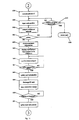
- the charge settlement type set at the IC card 20 is inputted by the customer into the ATM 1 via the customer operation unit 9.
- the ATM 1 tries out a plurality of types of charge settlement set at itself in a prescribed order of, for example, type code A, type code B and type code C.
- FIG. 14 is a flowchart showing this operation of the ATM 1.
- the ATM 1 When the IC card 20 is inserted, the ATM 1 reads the magnetic information stored in the magnetic stripe 201. When there is no type code data within the magnetic information read in, the ATM 1 determines that confirmation of the type is not possible and conveys the IC card 20 to the IC card reader/writer 5d (S61). The ATM 1 then displays the message "please designate the transaction institution for this IC card" and the name of the machine for which permitted transactions are possible is displayed (S62). A timer monitoring the presence of an input in accordance with this display is then made to operate and a customer input is awaited (S63).
- step 67 S64
- time out processing is executed.
- the ATM 1 selects control software 14n corresponding to the inputted type N, activates the IC card reader/writer 12n and activates the ATM card 200n installed at the IC card reader/writer 12n. At this time, the ATM card 200n accesses the IC card 200 (S65) and confirms whether or not the IC card 20 is appropriate (S66). When the compatibility of the IC card 20 is confirmed, the ATM card 20n carries out settlement transactions and access ends when the settlement transaction is complete.
- the ATM code 200n transmits a signal to the ATM 1 indicating that the card is not appropriate.
- the ATM 1 selects control software 14a corresponding to the type code A, drives the IC card reader/writer 12a and activates the ATM card 200a installed at the IC card reader/writer 12a.
- the ATM card 200a transmits a prescribed signal to the IC card 20, accesses the IC card 20 (S67) and confirms whether or not the IC card 20 has sent back an appropriate response with respect to this signal (S68).
- step 73 is then proceeded to if the IC card 20 sends back an appropriate response at this time.
- the ATM card 200a transmits a signal to the ATM 1 indicating that the IC card 20 is not a type code A card.
- the ATM 1 selects control software 14b corresponding to the type code B, drives the IC card reader/writer 12b, and activates the ATM card 200b installed at the IC card reader/writer 12b.
- the ATM card 200b transmits a prescribed signal to the IC card 20 and accesses the IC card 20 (S69) and confirms whether or not the IC card 20 sends back an appropriate response with respect to this signal (S70).
- step 73 is proceeded to if the IC card 20 sends back an appropriate response at this time.
- the ATM card 200b transmits a signal to the ATM 1 indicating that the IC card 20 is not a type code B card.
- the ATM 1 selects control software 14b corresponding to the type code C, drives the IC card reader/writer 12c, and activates the ATM card 200c installed at the IC card reader/writer 12c.
- the ATM card 200c transmits a prescribed signal to the IC card 20, accesses the IC card 20 (S71) and confirms whether or not the IC card 20 sends back an appropriate response with respect to this signal (S72). Step 73 is then proceeded to if the IC card 20 sends back an appropriate response.
- the AIM card 200c transmits a signal to the ATM 1 indicating that the IC card 20 is not a card of type code C.
- the ATM 1 displays that transactions are not possible at the customer operation unit 9 (S74), the IC card 20 is discharged from the card insertion/return opening 5a (S75) and the process is complete.
- the ATM card 200 confirms whether or not the IC card 20 is an appropriate card (S73).
- S73 the ATM card 200 confirms that the IC card 20 is appropriate, charge settling is carried out and the processing ends when the charge settlement is complete.
- the order of activation of the control software 14 can be set up based on the market share of the transaction conditions.
- the likelihood of the type of cash settlement set at the IC card 20 and the control software 14 matching is therefore increased and processing can therefore be carried out in a shorter time period.
- the ATM 1 can be capable of carrying out processing for more than three types of charge settlement.
- This kind of ATM 1 can be realized by, for example, making the number of built-in card reader/writers greater than three.
- This kind of ATM 1 can also be realized by making the configuration of the ATM card 200 installed in the card reader/writer 12 such that a plurality of charge settlement types can be carried out with a single card.
- the ATM card 200 is configured to store data such as that shown in FIG. 5, FIG. 6 and FIG. 7 in response to the types of charge settlement for which processing is possible.
- the ATM card 200 receives the type code and issuing body code etc. from the customer card at the time of a goods transaction, decides the charge settlement type in response to this data and charge settlement is then executed.
- This kind of ATM 1 is capable of a large number of types of transaction settlement using a single machine and a system in which a plurality of card issuing bodies can work in cooperation can therefore be provided.
- Control software can be automatically activated on the device side and accessing can be carried out without the customer inputting the settlement type, which is extremely convenient for inexperienced customers.
- a customer can make transactions using an automatic teller machine of a nearby financial institution even when a plurality of settlement conditions exist for transactions using electronic money. It is therefore no longer necessary for the customer to look for a branch of the financial institution that issued the card or to go to branches far away, which is extremely convenient for the customer.
- a plurality of IC card reader/writers can be stored if, for example, the space for one related money storage box is guaranteed. Further, as IC cards are extremely safe from a security point of view, a plurality of card reader/writers can be added by attachment to the rear side of the ATM and compatibility can therefore easily be achieved.
Description
Claims (4)
- An electronic transaction system, comprising: a first IC card (20) for customer for storing electronic money issued by a money issuer and; a terminal (1) capable of being inserted with the first IC card (20), said electronic transaction system being for transferring electronic money between the terminal (1) and the first card (20) when the first IC card (20) is inserted into the terminal (1),
wherein information specifying a type of electronic money is stored at the first IC card (20),
a plurality of second IC cards (200) for the terminal (1) for storing electronic money issued by different money issuers or for storing different types of electronic money issued by the same money issuer are provided at the terminal (1),
information specifying the type of the electronic money is read by the terminal (1) from the first IC card (20) when the first IC card (20) is inserted into the terminal (1),
a second IC card (200) storing electronic money of the type specified by this information is selected by the terminal (1), and
electronic money is transferred between the second IC card (200) selected by the terminal (1) and the first IC card (20). - The electronic transaction system of claim 1, wherein the terminal (1) selects a single second IC card (200) from the plurality of second IC cards (200) in a preset order when information specifying the electronic money type cannot be read from the first IC card (20), and electronic money is transferred between the second IC card (200) selected by the terminal (1) and the first IC card (20).
- The electronic transaction system of claim 1 or claim 2, wherein information specifying the electronic money type is set for each money issuer or said information is set for each type of electronic money when the money issuer is the same.
- The electronic transaction system of claims 1, 2 or 3, wherein the terminal (1) is an automatic teller machine.
Applications Claiming Priority (3)
| Application Number | Priority Date | Filing Date | Title |
|---|---|---|---|
| JP24310396 | 1996-09-13 | ||
| JP24310396 | 1996-09-13 | ||
| PCT/JP1997/003234 WO1998011514A1 (en) | 1996-09-13 | 1997-09-12 | Electronic transaction system |
Publications (3)
| Publication Number | Publication Date |
|---|---|
| EP0933731A1 EP0933731A1 (en) | 1999-08-04 |
| EP0933731A4 EP0933731A4 (en) | 2002-01-09 |
| EP0933731B1 true EP0933731B1 (en) | 2003-08-06 |
Family
ID=17098849
Family Applications (1)
| Application Number | Title | Priority Date | Filing Date |
|---|---|---|---|
| EP97940371A Expired - Lifetime EP0933731B1 (en) | 1996-09-13 | 1997-09-12 | Electronic transaction system |
Country Status (7)
| Country | Link |
|---|---|
| US (1) | US6338048B1 (en) |
| EP (1) | EP0933731B1 (en) |
| JP (1) | JP3363454B2 (en) |
| KR (1) | KR100451783B1 (en) |
| CN (1) | CN1132127C (en) |
| DE (1) | DE69723994T2 (en) |
| WO (1) | WO1998011514A1 (en) |
Families Citing this family (101)
| Publication number | Priority date | Publication date | Assignee | Title |
|---|---|---|---|---|
| US6861506B1 (en) | 1996-01-11 | 2005-03-01 | Corixa Corporation | Compositions and methods for the treatment and diagnosis of breast cancer |
| US7004385B1 (en) * | 2003-04-01 | 2006-02-28 | Diebold Self-Service Systems Division Of Diebold, Incorporated | Currency dispensing ATM with RFID card reader |
| US6615189B1 (en) * | 1998-06-22 | 2003-09-02 | Bank One, Delaware, National Association | Debit purchasing of stored value card for use by and/or delivery to others |
| US7809642B1 (en) | 1998-06-22 | 2010-10-05 | Jpmorgan Chase Bank, N.A. | Debit purchasing of stored value card for use by and/or delivery to others |
| EP1097437B1 (en) * | 1998-07-13 | 2002-11-20 | synfis Service GmbH | System and method for controlling cash transactions with customers within banking institutes |
| US7660763B1 (en) | 1998-11-17 | 2010-02-09 | Jpmorgan Chase Bank, N.A. | Customer activated multi-value (CAM) card |
| US6032136A (en) * | 1998-11-17 | 2000-02-29 | First Usa Bank, N.A. | Customer activated multi-value (CAM) card |
| JP2000250988A (en) * | 1999-03-01 | 2000-09-14 | Hitachi Ltd | Account settlement processing method and its implementation device, and medium where its processing program is recorded |
| JP4320481B2 (en) * | 1999-03-05 | 2009-08-26 | ソニー株式会社 | Electronic money system |
| JP3568426B2 (en) * | 1999-08-02 | 2004-09-22 | 株式会社ユーエフジェイ銀行 | Value cashing system and value cashing method |
| US7889052B2 (en) | 2001-07-10 | 2011-02-15 | Xatra Fund Mx, Llc | Authorizing payment subsequent to RF transactions |
| US8793160B2 (en) * | 1999-12-07 | 2014-07-29 | Steve Sorem | System and method for processing transactions |
| US6615190B1 (en) * | 2000-02-09 | 2003-09-02 | Bank One, Delaware, National Association | Sponsor funded stored value card |
| JP2001222740A (en) | 2000-02-09 | 2001-08-17 | Sony Corp | Electronic money system and electronic money terminal device |
| JP2001222765A (en) * | 2000-02-09 | 2001-08-17 | Sony Corp | Electronic money terminal device |
| JP2001306979A (en) * | 2000-04-24 | 2001-11-02 | Ntt Data Corp | Electronic settling method and electronic settlement system and recording medium with the same method programmed and recorded |
| US20020013770A1 (en) * | 2000-07-11 | 2002-01-31 | Toshikazu Higashi | Information processing method, and method for making payment for information processing by electronic money |
| AR033549A1 (en) * | 2000-08-07 | 2003-12-26 | Diebold Inc | AUTOMATIC MACHINE FOR BANK OPERATIONS, METHODS TO OPERATE IT AND LEGIBLE ENVIRONMENT BY COMPUTER |
| US7203657B1 (en) * | 2000-09-05 | 2007-04-10 | Noam Eli M | General packet-based payment and transaction method and system |
| US6631849B2 (en) * | 2000-12-06 | 2003-10-14 | Bank One, Delaware, National Association | Selectable multi-purpose card |
| US7313546B2 (en) * | 2001-05-23 | 2007-12-25 | Jp Morgan Chase Bank, N.A. | System and method for currency selectable stored value instrument |
| US7725427B2 (en) | 2001-05-25 | 2010-05-25 | Fred Bishop | Recurrent billing maintenance with radio frequency payment devices |
| US9454752B2 (en) * | 2001-07-10 | 2016-09-27 | Chartoleaux Kg Limited Liability Company | Reload protocol at a transaction processing entity |
| US8279042B2 (en) | 2001-07-10 | 2012-10-02 | Xatra Fund Mx, Llc | Iris scan biometrics on a payment device |
| US7705732B2 (en) * | 2001-07-10 | 2010-04-27 | Fred Bishop | Authenticating an RF transaction using a transaction counter |
| US8294552B2 (en) | 2001-07-10 | 2012-10-23 | Xatra Fund Mx, Llc | Facial scan biometrics on a payment device |
| US8548927B2 (en) | 2001-07-10 | 2013-10-01 | Xatra Fund Mx, Llc | Biometric registration for facilitating an RF transaction |
| US7360689B2 (en) | 2001-07-10 | 2008-04-22 | American Express Travel Related Services Company, Inc. | Method and system for proffering multiple biometrics for use with a FOB |
| US7735725B1 (en) | 2001-07-10 | 2010-06-15 | Fred Bishop | Processing an RF transaction using a routing number |
| US9024719B1 (en) | 2001-07-10 | 2015-05-05 | Xatra Fund Mx, Llc | RF transaction system and method for storing user personal data |
| US7249112B2 (en) | 2002-07-09 | 2007-07-24 | American Express Travel Related Services Company, Inc. | System and method for assigning a funding source for a radio frequency identification device |
| US20090008441A1 (en) * | 2001-07-10 | 2009-01-08 | Xatra Fund Mx, Llc | Tracking rf transaction activity using a transaction device identifier |
| US7303120B2 (en) | 2001-07-10 | 2007-12-04 | American Express Travel Related Services Company, Inc. | System for biometric security using a FOB |
| US20040232224A1 (en) * | 2001-07-10 | 2004-11-25 | American Express Travel Related Services Company, Inc. | Method for registering biometric for use with a fob |
| US8001054B1 (en) | 2001-07-10 | 2011-08-16 | American Express Travel Related Services Company, Inc. | System and method for generating an unpredictable number using a seeded algorithm |
| US7668750B2 (en) * | 2001-07-10 | 2010-02-23 | David S Bonalle | Securing RF transactions using a transactions counter |
| US9031880B2 (en) * | 2001-07-10 | 2015-05-12 | Iii Holdings 1, Llc | Systems and methods for non-traditional payment using biometric data |
| US20040236699A1 (en) | 2001-07-10 | 2004-11-25 | American Express Travel Related Services Company, Inc. | Method and system for hand geometry recognition biometrics on a fob |
| WO2003010701A1 (en) | 2001-07-24 | 2003-02-06 | First Usa Bank, N.A. | Multiple account card and transaction routing |
| US8020754B2 (en) | 2001-08-13 | 2011-09-20 | Jpmorgan Chase Bank, N.A. | System and method for funding a collective account by use of an electronic tag |
| US7311244B1 (en) | 2001-08-13 | 2007-12-25 | Jpmorgan Chase Bank, N.A. | System and method for funding a collective account by use of an electronic tag |
| US6945453B1 (en) * | 2001-08-13 | 2005-09-20 | Bank One Delaware N.A. | System and method for funding a collective account by use of an electronic tag |
| US8800857B1 (en) | 2001-08-13 | 2014-08-12 | Jpmorgan Chase Bank, N.A. | System and method for crediting loyalty program points and providing loyalty rewards by use of an electronic tag |
| US20070078719A1 (en) * | 2001-11-01 | 2007-04-05 | Jp Morgan Chase Bank | S/M for offering reward programs |
| US20100030675A1 (en) * | 2001-12-06 | 2010-02-04 | Hanan Christopher C | Payor focused business to business electronic invoice presentment and accounts payable reconciliation system and method |
| US6857565B2 (en) * | 2001-12-14 | 2005-02-22 | Damon Eugene Smith | Electronic traveler's checks |
| US20030172017A1 (en) * | 2002-03-11 | 2003-09-11 | Vincent Feingold | High performance multi-dimensional risk engines for enterprise wide market risk management |
| US7756896B1 (en) | 2002-03-11 | 2010-07-13 | Jp Morgan Chase Bank | System and method for multi-dimensional risk analysis |
| US7899753B1 (en) | 2002-03-25 | 2011-03-01 | Jpmorgan Chase Bank, N.A | Systems and methods for time variable financial authentication |
| US8751391B2 (en) * | 2002-03-29 | 2014-06-10 | Jpmorgan Chase Bank, N.A. | System and process for performing purchase transactions using tokens |
| US20040210498A1 (en) | 2002-03-29 | 2004-10-21 | Bank One, National Association | Method and system for performing purchase and other transactions using tokens with multiple chips |
| US20030236743A1 (en) * | 2002-06-25 | 2003-12-25 | Min Moon Ki | Electronic cash sharing system and method thereof |
| US8239304B1 (en) | 2002-07-29 | 2012-08-07 | Jpmorgan Chase Bank, N.A. | Method and system for providing pre-approved targeted products |
| JP2004086591A (en) * | 2002-08-27 | 2004-03-18 | Jcb:Kk | Charging system for network adaptive electric appliance |
| US6805287B2 (en) | 2002-09-12 | 2004-10-19 | American Express Travel Related Services Company, Inc. | System and method for converting a stored value card to a credit card |
| US7809595B2 (en) | 2002-09-17 | 2010-10-05 | Jpmorgan Chase Bank, Na | System and method for managing risks associated with outside service providers |
| US20040122736A1 (en) * | 2002-10-11 | 2004-06-24 | Bank One, Delaware, N.A. | System and method for granting promotional rewards to credit account holders |
| US20050027649A1 (en) * | 2003-02-27 | 2005-02-03 | Richard Cech | Event typer |
| CN1777911A (en) * | 2003-04-30 | 2006-05-24 | 比特瓦雷特股份有限公司 | Electronic currency management system, electronic currency management method and computer progromme |
| JP2004355085A (en) * | 2003-05-27 | 2004-12-16 | Nippon Telegr & Teleph Corp <Ntt> | Electronic value transfer method and service providing apparatus and service using apparatus used for this method |
| US8306907B2 (en) * | 2003-05-30 | 2012-11-06 | Jpmorgan Chase Bank N.A. | System and method for offering risk-based interest rates in a credit instrument |
| US7953663B1 (en) | 2003-09-04 | 2011-05-31 | Jpmorgan Chase Bank, N.A. | System and method for financial instrument pre-qualification and offering |
| JP2005122402A (en) * | 2003-10-15 | 2005-05-12 | Systemneeds Inc | Ic card system |
| JP2005128675A (en) * | 2003-10-22 | 2005-05-19 | Sanden Corp | Electronic money charger |
| US7314164B2 (en) * | 2004-07-01 | 2008-01-01 | American Express Travel Related Services Company, Inc. | System for biometric security using a smartcard |
| US7314165B2 (en) * | 2004-07-01 | 2008-01-01 | American Express Travel Related Services Company, Inc. | Method and system for smellprint recognition biometrics on a smartcard |
| US7325724B2 (en) | 2004-07-01 | 2008-02-05 | American Express Travel Related Services Company, Inc. | Method for registering a biometric for use with a smartcard |
| US7318550B2 (en) | 2004-07-01 | 2008-01-15 | American Express Travel Related Services Company, Inc. | Biometric safeguard method for use with a smartcard |
| US7363504B2 (en) | 2004-07-01 | 2008-04-22 | American Express Travel Related Services Company, Inc. | Method and system for keystroke scan recognition biometrics on a smartcard |
| US7341181B2 (en) * | 2004-07-01 | 2008-03-11 | American Express Travel Related Services Company, Inc. | Method for biometric security using a smartcard |
| US7392222B1 (en) | 2004-08-03 | 2008-06-24 | Jpmorgan Chase Bank, N.A. | System and method for providing promotional pricing |
| US20060095307A1 (en) * | 2004-11-01 | 2006-05-04 | Stevenson Jeffrey W | Method and system for establishing a defined benefit plan |
| US7401731B1 (en) | 2005-05-27 | 2008-07-22 | Jpmorgan Chase Bank, Na | Method and system for implementing a card product with multiple customized relationships |
| JP2007140807A (en) * | 2005-11-17 | 2007-06-07 | Brother Ind Ltd | Removable medium unit, removable medium unit control program and removable medium unit control method |
| JP2007148721A (en) * | 2005-11-28 | 2007-06-14 | Brother Ind Ltd | Removable medium device, removable medium device control program and removable medium device control method |
| US7784682B2 (en) | 2006-02-08 | 2010-08-31 | Jpmorgan Chase Bank, N.A. | System and method for granting promotional rewards to both customers and non-customers |
| US8408455B1 (en) | 2006-02-08 | 2013-04-02 | Jpmorgan Chase Bank, N.A. | System and method for granting promotional rewards to both customers and non-customers |
| US7753259B1 (en) | 2006-04-13 | 2010-07-13 | Jpmorgan Chase Bank, N.A. | System and method for granting promotional rewards to both customers and non-customers |
| US20080121699A1 (en) * | 2006-09-07 | 2008-05-29 | Datacard Corporation | Self service card kiosk with return and reissue capability |
| US7909247B2 (en) | 2006-10-27 | 2011-03-22 | American Express Travel Related Services Company, Inc. | Wireless transaction medium having combined magnetic stripe and radio frequency communications |
| US20080177659A1 (en) * | 2007-01-19 | 2008-07-24 | Timothy Douglas Lacey | Systems and methods for providing financial processing in conjunction with instant messaging and other communications |
| CN101261754A (en) * | 2007-03-07 | 2008-09-10 | 邱云南 | A value storage financial card with multiple applications |
| US8676642B1 (en) | 2007-07-05 | 2014-03-18 | Jpmorgan Chase Bank, N.A. | System and method for granting promotional rewards to financial account holders |
| CN101828395B (en) * | 2007-09-14 | 2014-10-29 | 松下航空电子公司 | System and method for interfacing a portable media device with a vehicle information system |
| US8417601B1 (en) | 2007-10-18 | 2013-04-09 | Jpmorgan Chase Bank, N.A. | Variable rate payment card |
| JP2009163559A (en) * | 2008-01-08 | 2009-07-23 | Toshiba Tec Corp | Electronic money processor |
| KR101122470B1 (en) * | 2009-06-08 | 2012-02-29 | 에스케이플래닛 주식회사 | System and method for distinguishing electronic money of muiti type, apparatus applied to the same |
| JP2012108646A (en) * | 2010-11-16 | 2012-06-07 | Fujitsu Telecom Networks Ltd | Electronic voting system |
| US9135020B2 (en) * | 2011-09-30 | 2015-09-15 | Ncr Corporation | Correlation of resources |
| US10049402B1 (en) | 2012-06-13 | 2018-08-14 | Jpmorgan Chase Bank, N.A. | ATM privacy system and method |
| KR101364880B1 (en) * | 2012-07-03 | 2014-02-20 | 주식회사 엘지씨엔에스 | Media processing apparatus, method for processing media and financial device using the same |
| US10395227B2 (en) | 2015-01-14 | 2019-08-27 | Tactilis Pte. Limited | System and method for reconciling electronic transaction records for enhanced security |
| US9607189B2 (en) | 2015-01-14 | 2017-03-28 | Tactilis Sdn Bhd | Smart card system comprising a card and a carrier |
| US10037528B2 (en) | 2015-01-14 | 2018-07-31 | Tactilis Sdn Bhd | Biometric device utilizing finger sequence for authentication |
| CN105913259A (en) * | 2016-03-25 | 2016-08-31 | 天地融科技股份有限公司 | Trade method and trade system of electronic signature device, and electronic signature device |
| EP3376482B1 (en) * | 2017-03-17 | 2022-06-22 | Wincor Nixdorf International GmbH | Document of value processing device and method for operating a document of value processing device |
| JP6978898B2 (en) * | 2017-11-01 | 2021-12-08 | シャープ株式会社 | Information processing equipment, information processing systems, control programs and control methods |
| JP6843818B2 (en) * | 2018-11-22 | 2021-03-17 | 三菱重工機械システム株式会社 | Card reader system and processing method |
| JP7365125B2 (en) * | 2019-02-20 | 2023-10-19 | 三菱重工機械システム株式会社 | Card processing device, toll machine, card processing method, and program |
| JP7327112B2 (en) * | 2019-11-26 | 2023-08-16 | 沖電気工業株式会社 | Media processing equipment and automatic transaction equipment |
| US11842037B2 (en) * | 2022-02-23 | 2023-12-12 | Capital One Services, Llc | Presentation and control of user interactions with a time-dependent user interface element |
Family Cites Families (29)
| Publication number | Priority date | Publication date | Assignee | Title |
|---|---|---|---|---|
| JPS5931746B2 (en) * | 1977-04-28 | 1984-08-03 | オムロン株式会社 | Transaction processing method |
| US4906828A (en) * | 1983-02-28 | 1990-03-06 | Paperless Accounting, Inc. | Electronic money purse and fund transfer system |
| US5140517A (en) * | 1984-03-19 | 1992-08-18 | Omron Tateisi Electronics Co. | IC card with keyboard for prestoring transaction data |
| JPH021049A (en) * | 1988-03-02 | 1990-01-05 | Hitachi Ltd | Transaction system, automatic bank transaction device, terminal equipment for settlement of account, withdrawal transaction method, deposit transaction method, and transfer transaction method |
| JPH0235568A (en) | 1988-07-25 | 1990-02-06 | Omron Tateisi Electron Co | Securities exchange |
| EP0348923A3 (en) | 1988-06-30 | 1991-03-13 | Omron Corporation | Apparatus for exchanging money to valuable papers |
| ATE120021T1 (en) * | 1988-07-20 | 1995-04-15 | Syspatronic Ag Spa | DATA CARRIER-CONTROLLED TERMINAL DEVICE IN A DATA EXCHANGE SYSTEM. |
| JP2936567B2 (en) * | 1988-08-24 | 1999-08-23 | ソニー株式会社 | Information record display card |
| US4960981A (en) * | 1989-01-17 | 1990-10-02 | Moneyfax, Inc. | Method of and system for electronic funds transfer via facsimile machines |
| JPH02111861U (en) * | 1989-02-27 | 1990-09-06 | ||
| JP3184196B2 (en) * | 1989-09-06 | 2001-07-09 | 株式会社富士通総研 | Electronic wallet system |
| JPH0398194A (en) | 1989-09-11 | 1991-04-23 | Chubu Nippon Denki Software Kk | Offline foreign currency exchanging device |
| JPH03116469A (en) | 1989-09-28 | 1991-05-17 | Olympus Optical Co Ltd | Optical disk driving device |
| JPH03223958A (en) * | 1990-01-29 | 1991-10-02 | Hitachi Ltd | Transaction inquiring method |
| JPH03116469U (en) * | 1990-03-13 | 1991-12-03 | ||
| US5036461A (en) * | 1990-05-16 | 1991-07-30 | Elliott John C | Two-way authentication system between user's smart card and issuer-specific plug-in application modules in multi-issued transaction device |
| JPH0477995A (en) * | 1990-07-20 | 1992-03-12 | Tokyo Electric Co Ltd | Merchandise sales data processor |
| JP2882012B2 (en) * | 1990-08-31 | 1999-04-12 | 松下電器産業株式会社 | Data transfer system and data transfer terminal |
| JPH04149723A (en) | 1990-10-12 | 1992-05-22 | Mita Ind Co Ltd | Ic card use device |
| JP3116469B2 (en) | 1991-11-01 | 2000-12-11 | セイコーエプソン株式会社 | Method of forming bump type electrode and method of manufacturing semiconductor device |
| DE69310255T2 (en) * | 1992-03-04 | 1997-08-14 | Thomson Multimedia Sa | Method and device for checking several chip cards |
| JP3403456B2 (en) * | 1993-06-24 | 2003-05-06 | 日本銀行 | Transaction method in electronic retail payment system |
| US5461217A (en) * | 1994-02-08 | 1995-10-24 | At&T Ipm Corp. | Secure money transfer techniques using smart cards |
| US5854581A (en) * | 1994-03-08 | 1998-12-29 | Oki Electric Industry Co., Ltd. | Transaction processing system and transaction processing method |
| JPH08190658A (en) * | 1995-01-11 | 1996-07-23 | Nippon Avionics Co Ltd | Prepaid card mutual use system |
| FR2729523A1 (en) * | 1995-01-16 | 1996-07-19 | Solaic Sa | Public telephone that can read user card and record memory card |
| JPH0950497A (en) * | 1995-08-09 | 1997-02-18 | Hitachi Ltd | Electronic money information transfer device |
| JPH09218928A (en) * | 1995-12-08 | 1997-08-19 | Hitachi Ltd | Ic card reader-writer and operation method therefor |
| CA2197933A1 (en) * | 1996-02-29 | 1997-08-29 | Masayuki Ohki | Ic card reader/writer and operation method thereof |
-
1997
- 1997-09-12 EP EP97940371A patent/EP0933731B1/en not_active Expired - Lifetime
- 1997-09-12 WO PCT/JP1997/003234 patent/WO1998011514A1/en active IP Right Grant
- 1997-09-12 KR KR10-1999-7001896A patent/KR100451783B1/en not_active IP Right Cessation
- 1997-09-12 JP JP51350898A patent/JP3363454B2/en not_active Expired - Fee Related
- 1997-09-12 CN CN97197890A patent/CN1132127C/en not_active Expired - Fee Related
- 1997-09-12 DE DE69723994T patent/DE69723994T2/en not_active Expired - Fee Related
- 1997-09-12 US US09/254,706 patent/US6338048B1/en not_active Expired - Lifetime
Also Published As
| Publication number | Publication date |
|---|---|
| EP0933731A4 (en) | 2002-01-09 |
| DE69723994D1 (en) | 2003-09-11 |
| DE69723994T2 (en) | 2004-07-22 |
| EP0933731A1 (en) | 1999-08-04 |
| CN1132127C (en) | 2003-12-24 |
| JP3363454B2 (en) | 2003-01-08 |
| CN1230269A (en) | 1999-09-29 |
| KR20000038035A (en) | 2000-07-05 |
| KR100451783B1 (en) | 2004-10-08 |
| WO1998011514A1 (en) | 1998-03-19 |
| US6338048B1 (en) | 2002-01-08 |
Similar Documents
| Publication | Publication Date | Title |
|---|---|---|
| EP0933731B1 (en) | Electronic transaction system | |
| US5952639A (en) | Depositing, withdrawal, balance check, exchange and transfer of electronic money in automatic cash handling machine | |
| EP0738404B1 (en) | A method and apparatus for distributing currency | |
| USRE36365E (en) | Method and apparatus for distributing currency | |
| US20040024700A1 (en) | Electronic funds transfer method and system | |
| JPH10162089A (en) | Electronic transaction system | |
| JPS61216095A (en) | Vending machine | |
| US20010014885A1 (en) | IC card and its controller, and a method for selection of IC card applications | |
| RU2145436C1 (en) | Devices and methods for retail trade | |
| KR100360052B1 (en) | Electronic transaction processing system | |
| JP2002170151A (en) | Vending machine | |
| US6345762B1 (en) | Automatic vending machine | |
| JPH10143725A (en) | Electronic transaction system | |
| JP3872194B2 (en) | Electronic trading system | |
| AU2002227009B2 (en) | Electronic funds transfer method and system | |
| JP4770081B2 (en) | Vending machine, management device, vending machine product sales system | |
| JP4915039B2 (en) | Point service system linked with cashout function | |
| JPH09259197A (en) | Electronic purse system | |
| KR100363204B1 (en) | System for exchange the items of an account use for vending machine and Method for exchange the items of an account | |
| JP2002279531A (en) | Commodity sales data processor, commodity sales data processing method and computer program | |
| JPH0830693A (en) | Transaction processing method | |
| JP2002279494A (en) | Automatic cash transaction method | |
| AU2002227009A1 (en) | Electronic funds transfer method and system | |
| JPH10222588A (en) | Electronic transaction system | |
| JPS62111382A (en) | Vending machine |
Legal Events
| Date | Code | Title | Description |
|---|---|---|---|
| PUAI | Public reference made under article 153(3) epc to a published international application that has entered the european phase |
Free format text: ORIGINAL CODE: 0009012 |
|
| 17P | Request for examination filed |
Effective date: 19990204 |
|
| AK | Designated contracting states |
Kind code of ref document: A1 Designated state(s): DE FR GB |
|
| K1C3 | Correction of patent application (complete document) published |
Effective date: 19990804 |
|
| A4 | Supplementary search report drawn up and despatched |
Effective date: 20011123 |
|
| AK | Designated contracting states |
Kind code of ref document: A4 Designated state(s): DE FR GB |
|
| RIC1 | Information provided on ipc code assigned before grant |
Free format text: 7G 07D 9/00 A, 7G 07D 1/04 B, 7G 07F 7/08 B, 7G 06F 19/00 B, 7G 06K 17/00 B, 7G 07F 7/10 B |
|
| 17Q | First examination report despatched |
Effective date: 20020426 |
|
| GRAH | Despatch of communication of intention to grant a patent |
Free format text: ORIGINAL CODE: EPIDOS IGRA |
|
| GRAH | Despatch of communication of intention to grant a patent |
Free format text: ORIGINAL CODE: EPIDOS IGRA |
|
| GRAA | (expected) grant |
Free format text: ORIGINAL CODE: 0009210 |
|
| AK | Designated contracting states |
Designated state(s): DE FR GB |
|
| REG | Reference to a national code |
Ref country code: GB Ref legal event code: FG4D |
|
| REF | Corresponds to: |
Ref document number: 69723994 Country of ref document: DE Date of ref document: 20030911 Kind code of ref document: P |
|
| ET | Fr: translation filed | ||
| PLBE | No opposition filed within time limit |
Free format text: ORIGINAL CODE: 0009261 |
|
| STAA | Information on the status of an ep patent application or granted ep patent |
Free format text: STATUS: NO OPPOSITION FILED WITHIN TIME LIMIT |
|
| 26N | No opposition filed |
Effective date: 20040507 |
|
| PGFP | Annual fee paid to national office [announced via postgrant information from national office to epo] |
Ref country code: DE Payment date: 20070906 Year of fee payment: 11 |
|
| PGFP | Annual fee paid to national office [announced via postgrant information from national office to epo] |
Ref country code: GB Payment date: 20070912 Year of fee payment: 11 |
|
| PGFP | Annual fee paid to national office [announced via postgrant information from national office to epo] |
Ref country code: FR Payment date: 20070914 Year of fee payment: 11 |
|
| GBPC | Gb: european patent ceased through non-payment of renewal fee |
Effective date: 20080912 |
|
| REG | Reference to a national code |
Ref country code: FR Ref legal event code: ST Effective date: 20090529 |
|
| PG25 | Lapsed in a contracting state [announced via postgrant information from national office to epo] |
Ref country code: DE Free format text: LAPSE BECAUSE OF NON-PAYMENT OF DUE FEES Effective date: 20090401 |
|
| PG25 | Lapsed in a contracting state [announced via postgrant information from national office to epo] |
Ref country code: FR Free format text: LAPSE BECAUSE OF NON-PAYMENT OF DUE FEES Effective date: 20080930 |
|
| PG25 | Lapsed in a contracting state [announced via postgrant information from national office to epo] |
Ref country code: GB Free format text: LAPSE BECAUSE OF NON-PAYMENT OF DUE FEES Effective date: 20080912 |