EP0937278B1 - Nonemissive displays and piezoelectric power supplies therefor - Google Patents
Nonemissive displays and piezoelectric power supplies therefor Download PDFInfo
- Publication number
- EP0937278B1 EP0937278B1 EP97910132A EP97910132A EP0937278B1 EP 0937278 B1 EP0937278 B1 EP 0937278B1 EP 97910132 A EP97910132 A EP 97910132A EP 97910132 A EP97910132 A EP 97910132A EP 0937278 B1 EP0937278 B1 EP 0937278B1
- Authority
- EP
- European Patent Office
- Prior art keywords
- display
- piezoelectric element
- particles
- potential difference
- electrodes
- Prior art date
- Legal status (The legal status is an assumption and is not a legal conclusion. Google has not performed a legal analysis and makes no representation as to the accuracy of the status listed.)
- Expired - Lifetime
Links
Images


Classifications
-
- G—PHYSICS
- G01—MEASURING; TESTING
- G01C—MEASURING DISTANCES, LEVELS OR BEARINGS; SURVEYING; NAVIGATION; GYROSCOPIC INSTRUMENTS; PHOTOGRAMMETRY OR VIDEOGRAMMETRY
- G01C22/00—Measuring distance traversed on the ground by vehicles, persons, animals or other moving solid bodies, e.g. using odometers, using pedometers
- G01C22/006—Pedometers
-
- B—PERFORMING OPERATIONS; TRANSPORTING
- B41—PRINTING; LINING MACHINES; TYPEWRITERS; STAMPS
- B41J—TYPEWRITERS; SELECTIVE PRINTING MECHANISMS, i.e. MECHANISMS PRINTING OTHERWISE THAN FROM A FORME; CORRECTION OF TYPOGRAPHICAL ERRORS
- B41J3/00—Typewriters or selective printing or marking mechanisms characterised by the purpose for which they are constructed
- B41J3/407—Typewriters or selective printing or marking mechanisms characterised by the purpose for which they are constructed for marking on special material
- B41J3/4076—Typewriters or selective printing or marking mechanisms characterised by the purpose for which they are constructed for marking on special material printing on rewritable, bistable "electronic paper" by a focused electric or magnetic field
-
- G—PHYSICS
- G02—OPTICS
- G02F—OPTICAL DEVICES OR ARRANGEMENTS FOR THE CONTROL OF LIGHT BY MODIFICATION OF THE OPTICAL PROPERTIES OF THE MEDIA OF THE ELEMENTS INVOLVED THEREIN; NON-LINEAR OPTICS; FREQUENCY-CHANGING OF LIGHT; OPTICAL LOGIC ELEMENTS; OPTICAL ANALOGUE/DIGITAL CONVERTERS
- G02F1/00—Devices or arrangements for the control of the intensity, colour, phase, polarisation or direction of light arriving from an independent light source, e.g. switching, gating or modulating; Non-linear optics
- G02F1/01—Devices or arrangements for the control of the intensity, colour, phase, polarisation or direction of light arriving from an independent light source, e.g. switching, gating or modulating; Non-linear optics for the control of the intensity, phase, polarisation or colour
- G02F1/13—Devices or arrangements for the control of the intensity, colour, phase, polarisation or direction of light arriving from an independent light source, e.g. switching, gating or modulating; Non-linear optics for the control of the intensity, phase, polarisation or colour based on liquid crystals, e.g. single liquid crystal display cells
- G02F1/133—Constructional arrangements; Operation of liquid crystal cells; Circuit arrangements
- G02F1/13306—Circuit arrangements or driving methods for the control of single liquid crystal cells
-
- G—PHYSICS
- G02—OPTICS
- G02F—OPTICAL DEVICES OR ARRANGEMENTS FOR THE CONTROL OF LIGHT BY MODIFICATION OF THE OPTICAL PROPERTIES OF THE MEDIA OF THE ELEMENTS INVOLVED THEREIN; NON-LINEAR OPTICS; FREQUENCY-CHANGING OF LIGHT; OPTICAL LOGIC ELEMENTS; OPTICAL ANALOGUE/DIGITAL CONVERTERS
- G02F1/00—Devices or arrangements for the control of the intensity, colour, phase, polarisation or direction of light arriving from an independent light source, e.g. switching, gating or modulating; Non-linear optics
- G02F1/01—Devices or arrangements for the control of the intensity, colour, phase, polarisation or direction of light arriving from an independent light source, e.g. switching, gating or modulating; Non-linear optics for the control of the intensity, phase, polarisation or colour
- G02F1/165—Devices or arrangements for the control of the intensity, colour, phase, polarisation or direction of light arriving from an independent light source, e.g. switching, gating or modulating; Non-linear optics for the control of the intensity, phase, polarisation or colour based on translational movement of particles in a fluid under the influence of an applied field
- G02F1/166—Devices or arrangements for the control of the intensity, colour, phase, polarisation or direction of light arriving from an independent light source, e.g. switching, gating or modulating; Non-linear optics for the control of the intensity, phase, polarisation or colour based on translational movement of particles in a fluid under the influence of an applied field characterised by the electro-optical or magneto-optical effect
- G02F1/167—Devices or arrangements for the control of the intensity, colour, phase, polarisation or direction of light arriving from an independent light source, e.g. switching, gating or modulating; Non-linear optics for the control of the intensity, phase, polarisation or colour based on translational movement of particles in a fluid under the influence of an applied field characterised by the electro-optical or magneto-optical effect by electrophoresis
-
- G—PHYSICS
- G02—OPTICS
- G02F—OPTICAL DEVICES OR ARRANGEMENTS FOR THE CONTROL OF LIGHT BY MODIFICATION OF THE OPTICAL PROPERTIES OF THE MEDIA OF THE ELEMENTS INVOLVED THEREIN; NON-LINEAR OPTICS; FREQUENCY-CHANGING OF LIGHT; OPTICAL LOGIC ELEMENTS; OPTICAL ANALOGUE/DIGITAL CONVERTERS
- G02F1/00—Devices or arrangements for the control of the intensity, colour, phase, polarisation or direction of light arriving from an independent light source, e.g. switching, gating or modulating; Non-linear optics
- G02F1/01—Devices or arrangements for the control of the intensity, colour, phase, polarisation or direction of light arriving from an independent light source, e.g. switching, gating or modulating; Non-linear optics for the control of the intensity, phase, polarisation or colour
- G02F1/165—Devices or arrangements for the control of the intensity, colour, phase, polarisation or direction of light arriving from an independent light source, e.g. switching, gating or modulating; Non-linear optics for the control of the intensity, phase, polarisation or colour based on translational movement of particles in a fluid under the influence of an applied field
- G02F1/1685—Operation of cells; Circuit arrangements affecting the entire cell
-
- G—PHYSICS
- G08—SIGNALLING
- G08B—SIGNALLING OR CALLING SYSTEMS; ORDER TELEGRAPHS; ALARM SYSTEMS
- G08B5/00—Visible signalling systems, e.g. personal calling systems, remote indication of seats occupied
- G08B5/22—Visible signalling systems, e.g. personal calling systems, remote indication of seats occupied using electric transmission; using electromagnetic transmission
- G08B5/222—Personal calling arrangements or devices, i.e. paging systems
- G08B5/223—Personal calling arrangements or devices, i.e. paging systems using wireless transmission
- G08B5/224—Paging receivers with visible signalling details
- G08B5/225—Display details
- G08B5/226—Display details with alphanumeric or graphic display means
-
- G—PHYSICS
- G02—OPTICS
- G02F—OPTICAL DEVICES OR ARRANGEMENTS FOR THE CONTROL OF LIGHT BY MODIFICATION OF THE OPTICAL PROPERTIES OF THE MEDIA OF THE ELEMENTS INVOLVED THEREIN; NON-LINEAR OPTICS; FREQUENCY-CHANGING OF LIGHT; OPTICAL LOGIC ELEMENTS; OPTICAL ANALOGUE/DIGITAL CONVERTERS
- G02F1/00—Devices or arrangements for the control of the intensity, colour, phase, polarisation or direction of light arriving from an independent light source, e.g. switching, gating or modulating; Non-linear optics
- G02F1/01—Devices or arrangements for the control of the intensity, colour, phase, polarisation or direction of light arriving from an independent light source, e.g. switching, gating or modulating; Non-linear optics for the control of the intensity, phase, polarisation or colour
- G02F1/165—Devices or arrangements for the control of the intensity, colour, phase, polarisation or direction of light arriving from an independent light source, e.g. switching, gating or modulating; Non-linear optics for the control of the intensity, phase, polarisation or colour based on translational movement of particles in a fluid under the influence of an applied field
- G02F1/1675—Constructional details
- G02F1/16757—Microcapsules
Definitions
- the present invention relates to electronic display elements, and more particularly to nonemissive displays.
- Nonemissive displays convey information using contrast differences, which are achieved by varying the reflectance of different frequencies of light; they are thus distinct from traditional emissive displays, which stimulate the eye by emitting light.
- One type of nonemissive display is an electrophoretic display, which utilizes the phenomenon of electrophoresis to achieve contrast. Electrophoresis refers to movement of charged particles in an applied electric field. When electrophoresis occurs in a liquid, the particles move with a velocity determined primarily by the viscous drag experienced by the particles, their charge, the dielectric properties of the liquid, and the magnitude of the applied field.
- US-A-4 919 521 discloses a nonemissive display comprising a pair of electrodes between which a solid matrix is located, the solid matrix comprises microcapsules containing a suspension of anisotropic particles dispersed in a fluid.
- An electrophoretic display utilizes charged particles of one color suspended in a dielectric liquid medium of a different color (that is, light reflected by the particles) is absorbed by the liquid.
- the suspension is housed in a cell located between (or partly defined by) a pair of oppositely disposed electrodes, one of which is transparent.
- the electrodes When the electrodes are operated to apply a DC or pulsed field across the medium, the particles migrate toward the electrode of opposite sign. The result is a visually observable color change.
- their color dominates the display; if the particles are drawn to the other electrode, however, they are obscured by the color of the liquid medium, which dominates instead.
- the particles maintain a strong uniform charge throughout the lifetime of the device and move as rapidly as possible under the influence of a relatively small electric field.
- the quantity t represents the "switching time,” i.e., the time required for the population of particles to migrate from one of the electrodes to the other.
- the system is usually selected to minimize t .
- the spacing between electrodes is as small as is necessary to ensure that the particles are completely obscured following migration away from the transparent electrode.
- Useful electrophoretic displays are bistable: their state persists even after the activating electric field is removed. This is generally achieved via residual charge on the electrodes and van der Waals interactions between the particles and the walls of the electrophoretic cell.
- the stability of current electrophoretic displays is limited. Although flocculation or settling of particles can be avoided by matching the density of the particles with that of the liquid medium, long-term particle agglomeration remains a problem. That is, cohesive forces among particles may eventually overcome dispersive forces, degrading the appearance and function of the display.
- particle agglomerations respond less efficiently to an applied field (increasing switching time) and are also more vulnerable to the action of gravity (limiting usefulness in arbitrary orientations); thus, if the display is oriented vertically, gravity can overcome adhesion to the cell wall and cause agglomerations to settle.
- an electrophoretic display as defined in Claim 1 below.
- the foregoing limitations are overcome by microencapsulating individual elements of an electrophoretic display.
- This approach eliminates the effects of agglomeration on a scale larger than the size of the capsule, which preferably is sufficiently small to be individually unnoticeable.
- the capsules function in a manner similar to pixels (although typically they are not individually addressable); even if agglomeration occurs, its effect is confined to a very small area.
- an upper limit to the possible size of an agglomeration - that is, by preventing accumulations larger than the particle content of a capsule - the bulk effects of diminished field responsiveness and vulnerability to gravity are likewise limited.
- the approach of the invention lends itself to production of relatively small multiple-capsule elements that can themselves be individually addressable components of a larger array.
- the elements can each present a circular profile and be arrayed as a matrix, functioning as pixels in an alphanumeric display.
- a preferred embodiment of the invention comprises an electrophorectic display having a substantially two-dimensional arrangement of microscopic containers ("microcapsules"), each microcapsule having therein an electrophoretic composition of a dielectric fluid and a suspension of particles that visually contrast with the dielectric liquid and also exhibit surface charges; a pair of electrodes, at least one of which is visually transparent, disposed on and covering opposite sides of the microcapsule arrangement; and means for creating a potential difference between the two electrodes, the potential difference causing the particles to migrate toward one of the electrodes.
- the microcapsule arrangement can be flat or curved; as used herein, the term "two-dimensional” refers to arrangements that may be fully planar, distorted or curved, and does not exclude some three-dimensional thickness.
- the arrangement can involve packing the microcapsules against one another in an array (generally one microcapsule thick), dispersing the microcapsules in a transparent matrix, or forming cavities or voids within such a matrix that themselves constitute the microcapsules.
- Embodiments of the invention provide novel means of electrically powering nonemissive displays using one or more piezoelectric elements (such as a sheet of polyvinylidene fluoride).
- the invention in this aspect may comprise a pair of oppositely disposed electrodes and, located therebetween, at least one display element, the display element being visually responsive to a potential difference between the electrodes; and a piezoelectric element connected to the electrodes, deformation of the piezoelectric element
- a display 120 includes a pair of planar electrodes 125, 130 which reside on opposite sides of a substantially planar arrangement of microscopic containers, or microcapsules, 133. At least electrode 130 is visually transparent so that a viewer may observe the color exhibited by portions of the microcapsules 133 adjacent to electrode 130.
- electrode 130 may comprise a semiconductor such as indium tin oxide evaporated or otherwise coated in a thin layer onto glass, mylar or other transparent substrate; the details of fabrication are well known to those skilled in the art, as are possible semiconductor alternatives to indium tin oxide (see, e.g., U.S. Patent Nos. 3,668,106 and 4,305,807, the entire disclosures of which are hereby incorporated by reference).
- a semiconductor such as indium tin oxide evaporated or otherwise coated in a thin layer onto glass, mylar or other transparent substrate; the details of fabrication are well known to those skilled in the art, as are possible semiconductor alternatives to indium tin oxide (see, e.g., U.S. Patent Nos. 3,668,106 and 4,305,807, the entire disclosures of which are hereby incorporated by reference).
- each microcapsule 133 is an electrophoretic suspension comprising a dielectric liquid 135 and a quantity of charged particles 137, the bulk liquid and the particles contrasting visually (i.e., exhibiting observably distinguishable colors or shades).
- a driver circuit 140 is electrically connected to electrodes 125, 130 and is capable of creating a sufficient potential difference between the electrodes to cause migration of particles 137 to one or the other electrode within an acceptable switching time.
- driver circuit 140 To impart the color of particles 137 to the display 120, driver circuit 140 creates an electric field (indicated by arrows 142) whose direction is such that particles 137 are attracted to, and migrate toward, electrode 130.
- microcapsules 133 are spherical and substantially tangent to one another; accordingly, if each microcapsule 133 contains a quantity of particles 137 sufficient to cover half the inner surface area under the influence of an electric field, attraction of particles 137 toward electrode 130 will impart the color of the particles to display 120 in a substantially uniform, uninterrupted manner.
- Microcapsules 133 need not be strictly spherical, but preferably have dimensions ranging from 5 to 500 ⁇ m, and ideally from 25 to 250 ⁇ m.
- the walls of microcapsules 133 should exhibit a resistivity similar to that of dielectric liquid 135. It may also be useful to match the refractive index of the microcapsules 133 with that of the electrophoretic composition.
- liquid 135 is hydrophobic, and techniques for encapsulating a hydrophobic internal phase are well characterized in the art. The process selected may impose limitations on the identity and properties of the dielectric liquid; for example, certain condensation processes may-require dielectric liquids with relatively high boiling points and low vapor pressures.
- an oil/water emulsion is formed by dispersing the electrophoretic composition (i.e., the hydrophobic dielectric liquid containing a suspension of the pigment particles 137) in an aqueous environment.
- One or more colloids are coacervated (i.e., agglomerated) out of the aqueous phase and deposited as shells around the oily droplets through control of temperature, pH and/or relative concentrations, thereby creating the microcapsule.
- Materials suitable for coacervation include gelatins and gum arabic. see, e.g., U.S. Patent No. 2,800,457.
- the "interfacial polymerization” approach relies on the presence of an oil-soluble monomer in the electrophoretic composition, which once again is present as an emulsion in an aqueous phase.
- the monomers in the minute hydrophobic droplets react with a monomer introduced into the aqueous phase, polymerizing at the interface between the droplets and the surrounding aqueous medium and forming shells around the droplets.
- the resulting walls are relatively thin and may be permeable, this process does not require the elevated temperatures characteristic of some other processes, and therefore affords greater flexibility in terms of choosing the dielectric liquid.
- our preferred microencapsulation technique is "in-situ polymerization," in which the monomers that will form the microcapsule shell are present in the aqueous phase rather than within the dispersed-phase droplets.
- the monomers polymerize to form a polymer with higher affinity for the internal phase than for the aqueous phase, thus condensing around the droplets as a skin.
- any of a variety of cross-linking agents borne in aqueous solution is deposited around microscopic oil droplets.
- cross-linking agents include formaldehyde, glyoxal, glutaraldehyde and other formaldehyde donors, trioxane, ethanolamine, ethylenediamine, boric acid, borates such as sodium borate, or macromolecular species such as gelatin, gum tragacanth, methylcellulose and A-stage formaldehyde condensation products.
- dielectric liquids may be used with the present invention; the criteria involved in their choice includes viscosity, dielectric constant, acquired charge and density.
- Preferred liquids include darkly colored hydrophobic fluids, such as isoparaffinic petroleum solvent or trichlorotrifluoroethane, or a mixture thereof; and other halogenated hydrocarbons, since these tend to exhibit desirably high densities (to match that of the dispersed particles) while having desirable electrical characteristics.
- a dye e.g., an oil dye such as Oil Blue N
- other colorant e.g., cobalt naphthenate for a violet color, manganese naphthenate for a brown color, or nickel naphthenate for a green color
- a wide range of pigment particles are also useful, the primary criteria governing their choice being appropriate charge, size and color.
- the particles can range in size from 100 ⁇ m to less than 1 ⁇ m, but a preferred size range is 5-25 ⁇ m.
- the particles may exhibit a native charge, or be charged explicitly using a charge-control agent, or may acquire a charge when suspended in the dielectric liquid.
- Useful particulate materials include titanium dioxide (TiO 2 ), which provides a high-reflectance white appearance; acetylene black or other black electrophotographic toner particles; other inorganic pigments; or organic pigments such as azo and phthalocyanine materials.
- a charge-control agent is added to the pigment particles to confer a surface charge (zeta potential).
- the charge-control agent may be capable of adsorbing directly onto the particle surfaces, or mixed in during fabrication of the particles. Generally, the charge-control agent confers a zeta potential equal to 50-100 elementary charges on the surface of a particle 1 ⁇ m in radius; this produces a sufficient electrophoretic mobility on the order of 10 -4 to 10 -5 cm 2 /V-sec.
- Suitable charge-control agents are well known in the art; they may be polymeric or non-polymeric in nature, and may also be ionic or non-ionic.
- Non-ionic polymeric charge-control agents include polyethylene, polybutene succinimide and various polyvinyl pyridine block copolymers. See, e.g. , U.S. Patent Nos.
- the charge-control agent should not interfere with the optical properties of the pigment particles.
- a mixture of TiO 2 particles and polyethylene is atomized to produce electrophoretic spheres that are largely polyethylene.
- the display 120 may be formed, for example, in the manner of fabricating liquid-crystal displays.
- microcapsules 133 containing the electrophoretic composition may be injected into a cell housing two spaced-apart electrodes.
- microcapsules 130 may be "printed" into a display by any of various methods known in the art, e.g., the techniques used to deposit pressure-rupturable microcapsules onto a substrate to create carbonless copy paper; in this case, the particles are printed onto one of the electrodes 125, 130, after which the other electrode is deposited, printed, or otherwise coated on top of the deposited microcapsules 130.
- microcapsules 133 are immobilized within a transparent matrix or binder 150 that is itself sandwiched between electrodes 125, 130.
- Matrix 150 is preferably a transparent polymeric material that may be cured (i.e., cross-linked from a low-viscosity state into extremely high viscosity) or otherwise solidified at relatively low temperatures, and which readily accepts, in its low-viscosity state, a dispersion of microcapsules.
- Useful materials include polyvinyl alcohols, gelatins, epoxies and other resins.
- the low-viscosity polymer precursor into which microcapsules 133 have been suspended at an adequate dispersion density, may be cured in a mold conforming to the two-dimensional or curved shape of electrodes 125, 130, or may instead utilize the electrodes as containment boundaries for an in-situ cure.
- microcapsules 133 can be voids or microscopic cavities in matrix 150 formed during its cure.
- the electrophoretic composition can be dispersed as an emulsion in the uncured (low-viscosity) precursor to matrix 150; curing of the precursor leaves the emulsion droplets suspended and immobilized within the matrix, effectively forming a polymer-dispersed electrophoretic display.
- the display can be arranged in any number of configurations, including a unitary, continuous display (i.e., a contiguous extent of microcapsules sandwiched between a single electrode pair); a row or other pattern of discrete groups of microcapsules controlled by a single electrode pair; or multiple-element arrangements containing a plurality of independently addressable display elements, each controlled by a separate electrode pair and comprising, for example, a single continuous display or a pattern of microcapsule groups.
- Driver 140 can be any suitable power supply, e.g., a DC or pulsed DC circuit, or an AC circuit (where the pulse width or AC period is greater than the switching time of the electrophoretic composition).
- driver 140 comprises a piezoelectric element.
- FIG. 2A which illustrates the manner in which such an element can be used to drive an electrophoretic display element 200, which comprises one or more individual electrophoretic displays.
- Physical deformation of the piezoelectric element 202 generates a voltage and current.
- the electrical output of element 202 may, if appropriate, be supplied directly to display 200; however, it is generally useful to condition the output first. For example, opposite deformations of element 202 produce voltages of opposite polarity; if element 202 is alternately deformed at a rate faster than the switching time of display 200, the display 200 will not respond.
- a voltage-conditioning circuit 204 may limit or augment the voltage produced by piezoelectric element 202, and may also include a smoothing filter to reduce variation in the voltage output or dampen the response of display 200. In operation, as the piezoelectric element is flexed in different directions, the electric field it produces changes in polarity, causing the charged particles in the electrophoretic display 200 to migrate away from one electrode and toward the other.
- display element 200 is not limited to the electrophoretic displays shown in FIGS. 1A-1B; the approach illustrated in FIG. 2A is applicable to any nonemissive display (e.g., liquid-crystal or electrophoretic displays), regardless of particular features, whose reponse characteristics are suited to the output of element 202.
- nonemissive display e.g., liquid-crystal or electrophoretic displays
- conditioning circuitry 204 is provided as a power supply to a processor 206, and reaches display element via one or more switches 208 controlled by processor 206.
- Voltage conditioner 204 therefore rectifies and limits the magnitude of the voltage reaching processor 206, which may itself be a programmable, single-chip microprocessor or other suitable circuitry for implementing a control function.
- Switches 208 may be transistors, the number of which depends on the number of individual electrophoretic display components in element 200.
- processor 206 can be configured to close one of the switches 208-and thereby provide power to one of the components of display element 200-upon detection of some external condition or at a predetermined time.
- FIG. 3 illustrates a particular application of the invention integrated within an article of footwear apparel 300, such as a shoe.
- the article 300 includes a bottom portion or sole 302.
- a flexible piezoelectric element 305 Disposed within sole 302 is a flexible piezoelectric element 305, e.g., a sheet of polyvinylidene difluoride.
- the two outputs 307 a , 307 b are connected to the electrodes of a first electrophoretic display 310, and in the opposite sense to the electrodes, of a second electrophoretic display 312.
- piezoelectric element 305 As the wearer of article 300 takes a step, s/he flexes piezoelectric element 305, producing a voltage of a first polarity sufficient to activate one of the displays 310, 312 (i.e., attract the particles to the visible electrode) and deactivate the other display (i.e., draw the particles away from the visible electrode). As the user completes a step, piezoelectric element 305 flattens, producing a voltage of opposite polarity and reversing the respective visual appearances of displays 310, 312. The switching time of the displays is faster than the rate of a normal gait. Again, the configuration shown in FIG. 3 can include voltage-conditioning circuitry if needed.
- FIG. 4A illustrates another application of the invention in the environment of footwear apparel, in this case a pedometer.
- An article of footwear 400 such as a running shoe, includes a bottom portion or sole 402 associated with a piezoelectric element 405.
- the outputs of piezoelectric element 405 are connected to a control circuit, described below, that governs the operation of a series of individual electrophoretic displays 412 a-g .
- the number of such displays “turned on” (or “turned off”) at any time reflects the number of deformations of piezoelectric element 405 and, hence, the number of steps taken. As shown in FIG.
- a suitable circuit 410 includes a full-wave rectifier or bridge 415, the rectified output of which is provided to a capacitor 417 connected in parallel with electrophoretic displays 412 a-g . Each display is also connected to a respective diode 420 a-g . The diodes 420 a-g in the series have increasingly greater breakdown voltages. In operation, all of the electrophoretic displays are initially in the same state. Regular flexing and straightening of piezoelectric element 405 results in an approximately AC voltage output, which is rectified by bridge 415. Each pulse from bridge 415 adds charge onto the plates of capacitor 417, increasing the voltage across the capacitor and, hence, across the diode/display pairs.
- Each of the displays 412 a-g changes state only when the accumulated charge on capacitor 417 exceeds the breakdown voltage of the associated diode.
- the charge on capacitor 417 reflects the number of steps taken, which therefore determines the number of displays 412 a-g that will have changed state.
- the user activates a switch (not shown) which reverses the connection of capacitor 417 across the diode/display pairs, bypassing the diodes and resetting the displays, and subsequently discharging capacitor 417.
- the circuit may also include an additional diode or other means for reducing or eliminating the high voltages caused by rapid foot travel, and means for programming the length of the user's stride so that the display reflects distance instead of steps taken.
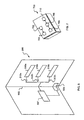
- FIG. 5 illustrates the manner in which the invention can be applied to a paper substrate, such as a book, periodical or greeting card.
- a greeting card 500 comprises a central fold 502 and a piezoelectric element 505 disposed thereon.
- Piezoelectric element 505 is connected (e.g., via a pair of foil traces or other conductors) to a driver circuit 507, which is itself connected to a series of three electrophoretic displays 510 a , 510 b , 510 c via an associated, user-actuable switch 512 a , 512 b , 512 c .
- Each of displays 510 a , 510 b , 510 c may spell out, for example, a different message.
- Circuit 507 includes a capacitive storage device that accumulates charge from the current produced by the user's opening of card 500, which deforms piezoelectric element 505. The stored charge is transferred to one of the displays 510 a , 510 b , 510 c through the user's selection of the appropriate switch.
- a similar arrangement can be used in conjunction with a book or periodical.
- the piezoelectric element powering an electrophoretic display need not be activated by direct deformation. Instead, it can be driven by acoustic coupling to another piezoelectric element that is itself subjected to a varying electric field (causing it to deform in proportion to the magnitude of the applied field). Such coupling can conveniently take place on length scales of 5 inches or less for typical piezoelectric displays.
- FIG. 6A shows how this effect can be exploited in the context of a wristwatch 600.
- a piezoelectric element 604 Inside the watch case 602 is a piezoelectric element 604 and an oscillator circuit 606; both of these components may be associated with the timekeeping function of watch 600.
- the oscillator 606 receives power from an autonomous source (e.g., a battery, not shown) and applies an AC current to piezoelectric element 604.
- Attached to (or embedded within) the watch band 610 is a second piezoelectric element 612 acoustically coupled to piezoelectric element 604.
- the 4 outputs of element 612 are provided to a driver circuit 614, which utilizes electrical energy from element 612 to power an electrophoretic display 616. With this simple arrangement, the display 616 would constantly be “turned on.”
- driver circuits 606 and 614 are preferably somewhat more sophisticated, as illustrated in FIG. 6B.
- Driver 606 is capable of oscillation at two or more frequences f 1 , f 2 .
- Driver circuit 614 includes a pair of notch or bandpass filters 620, 622 each tuned to a different one of the frequencies f 1 , f 2 . That is, each of filters 620 operates within a very narrow frequency band, dropping (or passing) one of the frequencies f 1 , f 2 without affecting other frequencies.
- the outputs of filters 620, 622 are oppositely connected to display 616; the filters also contain rectifiers so that their outputs to display 616 do not vary in polarity, and any other conditioning circuitry desired for the particular application.
- filter 620 drops frequency f 1 and filter 622 drops frequency f 2 .
- Operation of driver 606 at f 1 acoustically couples piezoelectric elements 604 and 612; however, electrical energy from piezoelectric element 612 reach display 616 only through filter 622, placing display 616 in a particular visual state.
- Operation of driver 606 at f 2 reverses the effect produced by filter 622, placing display 616 in the opposite state, since electrical energy passes only through filter 620.
- the foregoing circuit is useful, for example, in setting and resetting a visual alarm.
- such a device 700 includes an autonomously powered driver circuit 702 that activates a piezoelectric speaker 704 upon receiving a broadcast radio signal from a central station.
- driver circuit 702 that activates a piezoelectric speaker 704 upon receiving a broadcast radio signal from a central station.
- a second piezoelectric element 706 acoustically coupled to speaker 704; driver circuitry 708 as discussed previously; and an electrophoretic display 710.
- speaker 704 produces its audible alarm
- piezoelectric element 706 causes display 710 to change state, thereby providing a visual alarm indication.
- the display 710 can be used to convey other useful information to the user of a watch, pages, cellular telephone or other portable electronic device (e.g., the status of the battery).
Description
- The present invention relates to electronic display elements, and more particularly to nonemissive displays.
- Nonemissive displays convey information using contrast differences, which are achieved by varying the reflectance of different frequencies of light; they are thus distinct from traditional emissive displays, which stimulate the eye by emitting light. One type of nonemissive display is an electrophoretic display, which utilizes the phenomenon of electrophoresis to achieve contrast. Electrophoresis refers to movement of charged particles in an applied electric field. When electrophoresis occurs in a liquid, the particles move with a velocity determined primarily by the viscous drag experienced by the particles, their charge, the dielectric properties of the liquid, and the magnitude of the applied field.
- US-A-4 919 521 discloses a nonemissive display comprising a pair of electrodes between which a solid matrix is located, the solid matrix comprises microcapsules containing a suspension of anisotropic particles dispersed in a fluid.
- An electrophoretic display utilizes charged particles of one color suspended in a dielectric liquid medium of a different color (that is, light reflected by the particles) is absorbed by the liquid. The suspension is housed in a cell located between (or partly defined by) a pair of oppositely disposed electrodes, one of which is transparent. When the electrodes are operated to apply a DC or pulsed field across the medium, the particles migrate toward the electrode of opposite sign. The result is a visually observable color change. In particular, when a sufficient number of the particles reach the transparent electrode, their color dominates the display; if the particles are drawn to the other electrode, however, they are obscured by the color of the liquid medium, which dominates instead.
- Ideally, the particles maintain a strong uniform charge throughout the lifetime of the device and move as rapidly as possible under the influence of a relatively small electric field. The switching time of suspended particles located between two electrodes is given by
- Useful electrophoretic displays are bistable: their state persists even after the activating electric field is removed. This is generally achieved via residual charge on the electrodes and van der Waals interactions between the particles and the walls of the electrophoretic cell. Unfortunately, the stability of current electrophoretic displays is limited. Although flocculation or settling of particles can be avoided by matching the density of the particles with that of the liquid medium, long-term particle agglomeration remains a problem. That is, cohesive forces among particles may eventually overcome dispersive forces, degrading the appearance and function of the display. For example, particle agglomerations respond less efficiently to an applied field (increasing switching time) and are also more vulnerable to the action of gravity (limiting usefulness in arbitrary orientations); thus, if the display is oriented vertically, gravity can overcome adhesion to the cell wall and cause agglomerations to settle.
- According to the present invention, there is provided an electrophoretic display as defined in Claim 1 below.
- According to the present invention, there is further provided a nonemissive display system as defined in Claim 22 or Claim 24 below.
- In accordance with embodiments of the invention, the foregoing limitations are overcome by microencapsulating individual elements of an electrophoretic display. This approach eliminates the effects of agglomeration on a scale larger than the size of the capsule, which preferably is sufficiently small to be individually unnoticeable. Thus, the capsules function in a manner similar to pixels (although typically they are not individually addressable); even if agglomeration occurs, its effect is confined to a very small area. Furthermore, by setting an upper limit to the possible size of an agglomeration - that is, by preventing accumulations larger than the particle content of a capsule - the bulk effects of diminished field responsiveness and vulnerability to gravity are likewise limited.
- Although, again, individual capsules within a display element are typically not individually addressed, the approach of the invention lends itself to production of relatively small multiple-capsule elements that can themselves be individually addressable components of a larger array. For example, the elements can each present a circular profile and be arrayed as a matrix, functioning as pixels in an alphanumeric display.
- A preferred embodiment of the invention comprises an electrophorectic display having a substantially two-dimensional arrangement of microscopic containers ("microcapsules"), each microcapsule having therein an electrophoretic composition of a dielectric fluid and a suspension of particles that visually contrast with the dielectric liquid and also exhibit surface charges; a pair of electrodes, at least one of which is visually transparent, disposed on and covering opposite sides of the microcapsule arrangement; and means for creating a potential difference between the two electrodes, the potential difference causing the particles to migrate toward one of the electrodes. The microcapsule arrangement can be flat or curved; as used herein, the term "two-dimensional" refers to arrangements that may be fully planar, distorted or curved, and does not exclude some three-dimensional thickness. The arrangement can involve packing the microcapsules against one another in an array (generally one microcapsule thick), dispersing the microcapsules in a transparent matrix, or forming cavities or voids within such a matrix that themselves constitute the microcapsules.
- Embodiments of the invention provide novel means of electrically powering nonemissive displays using one or more piezoelectric elements (such as a sheet of polyvinylidene fluoride). Generally, the invention in this aspect may comprise a pair of oppositely disposed electrodes and, located therebetween, at least one display element, the display element being visually responsive to a potential difference between the electrodes; and a piezoelectric element connected to the electrodes, deformation of the piezoelectric element
- The foregoing discussion will be understood more readily from the following detailed description of the invention, when taken in conjunction with the accompanying drawings, in which:
- FIGS. 1A-1B are enlarged sectional views showing microencapsulated electrophoretic display arrangements in accordance with the present invention;
- FIGS. 2A and 2B schematically illustrate piezoelectric driver circuitry useful for operating nonemissive displays including (but not limited to) those depicted in FIGS. 1A-1B;
- FIG. 3 is a schematic elevation of a specific application of the invention in a footwear environment;
- FIG. 4A is a schematic elevation of another footwear application;
- FIG. 4B schematically illustrates representative circuitry for implementing the application shown in FIG. 4A;
- FIG. 5 is a partially schematic isometric view of a specific application of the invention in a paper publication environment;
- FIG. 6A is a partly schematic plan view of a specific application of the invention in a wristwatch environment; and
- FIG. 6B schematically illustrates representative circuitry for implementing the application shown in FIG. 7A;
- FIG. 7 is a partially schematic isometric view of the invention implemented in an acoustically coupled mode.
-
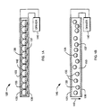
- Refer first to FIGS. 1A-1B, which illustrate alternative embodiments of microencapsulated electrophoretic display arrangements in accordance with the present invention. In FIG. 1A, a
display 120 includes a pair ofplanar electrodes electrode 130 is visually transparent so that a viewer may observe the color exhibited by portions of themicrocapsules 133 adjacent toelectrode 130. For example,electrode 130 may comprise a semiconductor such as indium tin oxide evaporated or otherwise coated in a thin layer onto glass, mylar or other transparent substrate; the details of fabrication are well known to those skilled in the art, as are possible semiconductor alternatives to indium tin oxide (see, e.g., U.S. Patent Nos. 3,668,106 and 4,305,807, the entire disclosures of which are hereby incorporated by reference). - Within each
microcapsule 133 is an electrophoretic suspension comprising adielectric liquid 135 and a quantity of chargedparticles 137, the bulk liquid and the particles contrasting visually (i.e., exhibiting observably distinguishable colors or shades). Adriver circuit 140 is electrically connected toelectrodes particles 137 to one or the other electrode within an acceptable switching time. - To impart the color of
particles 137 to thedisplay 120,driver circuit 140 creates an electric field (indicated by arrows 142) whose direction is such thatparticles 137 are attracted to, and migrate toward,electrode 130. In the illustrated embodiment,microcapsules 133 are spherical and substantially tangent to one another; accordingly, if eachmicrocapsule 133 contains a quantity ofparticles 137 sufficient to cover half the inner surface area under the influence of an electric field, attraction ofparticles 137 towardelectrode 130 will impart the color of the particles to display 120 in a substantially uniform, uninterrupted manner. -
Microcapsules 133 need not be strictly spherical, but preferably have dimensions ranging from 5 to 500 µm, and ideally from 25 to 250 µm. The walls ofmicrocapsules 133 should exhibit a resistivity similar to that ofdielectric liquid 135. It may also be useful to match the refractive index of themicrocapsules 133 with that of the electrophoretic composition. Ordinarily, liquid 135 is hydrophobic, and techniques for encapsulating a hydrophobic internal phase are well characterized in the art. The process selected may impose limitations on the identity and properties of the dielectric liquid; for example, certain condensation processes may-require dielectric liquids with relatively high boiling points and low vapor pressures. - In one approach, known as "coacervation," an oil/water emulsion is formed by dispersing the electrophoretic composition (i.e., the hydrophobic dielectric liquid containing a suspension of the pigment particles 137) in an aqueous environment. One or more colloids are coacervated (i.e., agglomerated) out of the aqueous phase and deposited as shells around the oily droplets through control of temperature, pH and/or relative concentrations, thereby creating the microcapsule. Materials suitable for coacervation include gelatins and gum arabic. see, e.g., U.S. Patent No. 2,800,457.
- The "interfacial polymerization" approach relies on the presence of an oil-soluble monomer in the electrophoretic composition, which once again is present as an emulsion in an aqueous phase. The monomers in the minute hydrophobic droplets react with a monomer introduced into the aqueous phase, polymerizing at the interface between the droplets and the surrounding aqueous medium and forming shells around the droplets. Although the resulting walls are relatively thin and may be permeable, this process does not require the elevated temperatures characteristic of some other processes, and therefore affords greater flexibility in terms of choosing the dielectric liquid.
- Our preferred microencapsulation technique is "in-situ polymerization," in which the monomers that will form the microcapsule shell are present in the aqueous phase rather than within the dispersed-phase droplets. The monomers polymerize to form a polymer with higher affinity for the internal phase than for the aqueous phase, thus condensing around the droplets as a skin. In one especially useful in-situ polymerization processes, urea and formaldehyde condense in the presence of poly(acrylic acid); see U.S. Patent No. 4,001,140. In other useful process, described in U.S. Patent No. 4,273,672, any of a variety of cross-linking agents borne in aqueous solution is deposited around microscopic oil droplets. Such cross-linking agents include formaldehyde, glyoxal, glutaraldehyde and other formaldehyde donors, trioxane, ethanolamine, ethylenediamine, boric acid, borates such as sodium borate, or macromolecular species such as gelatin, gum tragacanth, methylcellulose and A-stage formaldehyde condensation products.
- Other useful techniques for creating microcapsules include mechanical methods, as are well known to those skilled in the art and described, for example, in U.S. Patent No. 3,585,381.
- A wide range of dielectric liquids may be used with the present invention; the criteria involved in their choice includes viscosity, dielectric constant, acquired charge and density. Preferred liquids include darkly colored hydrophobic fluids, such as isoparaffinic petroleum solvent or trichlorotrifluoroethane, or a mixture thereof; and other halogenated hydrocarbons, since these tend to exhibit desirably high densities (to match that of the dispersed particles) while having desirable electrical characteristics. To further darken or impart a specific color to the liquid, a dye (e.g., an oil dye such as Oil Blue N) or other colorant (e.g., cobalt naphthenate for a violet color, manganese naphthenate for a brown color, or nickel naphthenate for a green color) can be added thereto.
- A wide range of pigment particles are also useful, the primary criteria governing their choice being appropriate charge, size and color. The particles can range in size from 100 µm to less than 1 µm, but a preferred size range is 5-25 µm. The particles may exhibit a native charge, or be charged explicitly using a charge-control agent, or may acquire a charge when suspended in the dielectric liquid. Useful particulate materials include titanium dioxide (TiO2), which provides a high-reflectance white appearance; acetylene black or other black electrophotographic toner particles; other inorganic pigments; or organic pigments such as azo and phthalocyanine materials. Typically, a charge-control agent is added to the pigment particles to confer a surface charge (zeta potential). The charge-control agent may be capable of adsorbing directly onto the particle surfaces, or mixed in during fabrication of the particles. Generally, the charge-control agent confers a zeta potential equal to 50-100 elementary charges on the surface of a particle 1 µm in radius; this produces a sufficient electrophoretic mobility on the order of 10-4 to 10-5 cm2/V-sec. Suitable charge-control agents are well known in the art; they may be polymeric or non-polymeric in nature, and may also be ionic or non-ionic. Non-ionic polymeric charge-control agents include polyethylene, polybutene succinimide and various polyvinyl pyridine block copolymers. See, e.g., U.S. Patent Nos. 5,380,362, 5,066,559 and 4,298,448 The charge-control agent (and any underlying coating) should not interfere with the optical properties of the pigment particles. In a preferred embodiment, a mixture of TiO2 particles and polyethylene is atomized to produce electrophoretic spheres that are largely polyethylene.
- The
display 120 may be formed, for example, in the manner of fabricating liquid-crystal displays. For example, after their formation,microcapsules 133 containing the electrophoretic composition may be injected into a cell housing two spaced-apart electrodes. Alternatively,microcapsules 130 may be "printed" into a display by any of various methods known in the art, e.g., the techniques used to deposit pressure-rupturable microcapsules onto a substrate to create carbonless copy paper; in this case, the particles are printed onto one of theelectrodes microcapsules 130. - In an
alternative embodiment 145, illustrated in FIG. 1B,microcapsules 133 are immobilized within a transparent matrix orbinder 150 that is itself sandwiched betweenelectrodes particles 137 towardtransparent electrode 130. So long asmicrocapsules 133 are dispersed withinmatrix 150 uniformly and at sufficient density, the resulting visual appearance will be uniform.Matrix 150 is preferably a transparent polymeric material that may be cured (i.e., cross-linked from a low-viscosity state into extremely high viscosity) or otherwise solidified at relatively low temperatures, and which readily accepts, in its low-viscosity state, a dispersion of microcapsules. Useful materials include polyvinyl alcohols, gelatins, epoxies and other resins. - The low-viscosity polymer precursor, into which
microcapsules 133 have been suspended at an adequate dispersion density, may be cured in a mold conforming to the two-dimensional or curved shape ofelectrodes - Alternatively and not falling within the scope of the present invention,
microcapsules 133 can be voids or microscopic cavities inmatrix 150 formed during its cure. For example, the electrophoretic composition can be dispersed as an emulsion in the uncured (low-viscosity) precursor tomatrix 150; curing of the precursor leaves the emulsion droplets suspended and immobilized within the matrix, effectively forming a polymer-dispersed electrophoretic display. - The display can be arranged in any number of configurations, including a unitary, continuous display (i.e., a contiguous extent of microcapsules sandwiched between a single electrode pair); a row or other pattern of discrete groups of microcapsules controlled by a single electrode pair; or multiple-element arrangements containing a plurality of independently addressable display elements, each controlled by a separate electrode pair and comprising, for example, a single continuous display or a pattern of microcapsule groups.
Driver 140 can be any suitable power supply, e.g., a DC or pulsed DC circuit, or an AC circuit (where the pulse width or AC period is greater than the switching time of the electrophoretic composition). - In accordance with another aspect of the invention, however,
driver 140 comprises a piezoelectric element. Refer to FIG. 2A, which illustrates the manner in which such an element can be used to drive anelectrophoretic display element 200, which comprises one or more individual electrophoretic displays. Physical deformation of thepiezoelectric element 202 generates a voltage and current. The electrical output ofelement 202 may, if appropriate, be supplied directly todisplay 200; however, it is generally useful to condition the output first. For example, opposite deformations ofelement 202 produce voltages of opposite polarity; ifelement 202 is alternately deformed at a rate faster than the switching time ofdisplay 200, thedisplay 200 will not respond. A voltage-conditioning circuit 204 may limit or augment the voltage produced bypiezoelectric element 202, and may also include a smoothing filter to reduce variation in the voltage output or dampen the response ofdisplay 200. In operation, as the piezoelectric element is flexed in different directions, the electric field it produces changes in polarity, causing the charged particles in theelectrophoretic display 200 to migrate away from one electrode and toward the other. - It should be stressed that
display element 200 is not limited to the electrophoretic displays shown in FIGS. 1A-1B; the approach illustrated in FIG. 2A is applicable to any nonemissive display (e.g., liquid-crystal or electrophoretic displays), regardless of particular features, whose reponse characteristics are suited to the output ofelement 202. - A more elaborate arrangement is shown in FIG. 2B. Here, the output of
conditioning circuitry 204 is provided as a power supply to aprocessor 206, and reaches display element via one ormore switches 208 controlled byprocessor 206.Voltage conditioner 204 therefore rectifies and limits the magnitude of thevoltage reaching processor 206, which may itself be a programmable, single-chip microprocessor or other suitable circuitry for implementing a control function.Switches 208 may be transistors, the number of which depends on the number of individual electrophoretic display components inelement 200. For example,processor 206 can be configured to close one of the switches 208-and thereby provide power to one of the components of display element 200-upon detection of some external condition or at a predetermined time. - Refer now to FIG. 3, which illustrates a particular application of the invention integrated within an article of
footwear apparel 300, such as a shoe. Thearticle 300 includes a bottom portion or sole 302. Disposed within sole 302 is a flexiblepiezoelectric element 305, e.g., a sheet of polyvinylidene difluoride. The twooutputs electrophoretic display 310, and in the opposite sense to the electrodes, of a secondelectrophoretic display 312. As the wearer ofarticle 300 takes a step, s/he flexespiezoelectric element 305, producing a voltage of a first polarity sufficient to activate one of thedisplays 310, 312 (i.e., attract the particles to the visible electrode) and deactivate the other display (i.e., draw the particles away from the visible electrode). As the user completes a step,piezoelectric element 305 flattens, producing a voltage of opposite polarity and reversing the respective visual appearances ofdisplays - FIG. 4A illustrates another application of the invention in the environment of footwear apparel, in this case a pedometer. An article of
footwear 400, such as a running shoe, includes a bottom portion or sole 402 associated with apiezoelectric element 405. The outputs ofpiezoelectric element 405 are connected to a control circuit, described below, that governs the operation of a series of individualelectrophoretic displays 412a-g. The number of such displays "turned on" (or "turned off") at any time reflects the number of deformations ofpiezoelectric element 405 and, hence, the number of steps taken. As shown in FIG. 4B, asuitable circuit 410 includes a full-wave rectifier orbridge 415, the rectified output of which is provided to acapacitor 417 connected in parallel withelectrophoretic displays 412a-g. Each display is also connected to arespective diode 420a-g. Thediodes 420a-g in the series have increasingly greater breakdown voltages. In operation, all of the electrophoretic displays are initially in the same state. Regular flexing and straightening ofpiezoelectric element 405 results in an approximately AC voltage output, which is rectified bybridge 415. Each pulse frombridge 415 adds charge onto the plates ofcapacitor 417, increasing the voltage across the capacitor and, hence, across the diode/display pairs. Each of thedisplays 412a-g changes state only when the accumulated charge oncapacitor 417 exceeds the breakdown voltage of the associated diode. The charge oncapacitor 417, of course, reflects the number of steps taken, which therefore determines the number ofdisplays 412a-g that will have changed state. To reset the device, the user activates a switch (not shown) which reverses the connection ofcapacitor 417 across the diode/display pairs, bypassing the diodes and resetting the displays, and subsequently dischargingcapacitor 417. The circuit may also include an additional diode or other means for reducing or eliminating the high voltages caused by rapid foot travel, and means for programming the length of the user's stride so that the display reflects distance instead of steps taken. - FIG. 5 illustrates the manner in which the invention can be applied to a paper substrate, such as a book, periodical or greeting card. In the depicted embodiment, a
greeting card 500 comprises acentral fold 502 and apiezoelectric element 505 disposed thereon.Piezoelectric element 505 is connected (e.g., via a pair of foil traces or other conductors) to adriver circuit 507, which is itself connected to a series of threeelectrophoretic displays actuable switch displays Circuit 507 includes a capacitive storage device that accumulates charge from the current produced by the user's opening ofcard 500, which deformspiezoelectric element 505. The stored charge is transferred to one of thedisplays - The piezoelectric element powering an electrophoretic display need not be activated by direct deformation. Instead, it can be driven by acoustic coupling to another piezoelectric element that is itself subjected to a varying electric field (causing it to deform in proportion to the magnitude of the applied field). Such coupling can conveniently take place on length scales of 5 inches or less for typical piezoelectric displays.
- Refer to FIG. 6A, which shows how this effect can be exploited in the context of a
wristwatch 600. Inside thewatch case 602 is apiezoelectric element 604 and anoscillator circuit 606; both of these components may be associated with the timekeeping function ofwatch 600. Theoscillator 606 receives power from an autonomous source (e.g., a battery, not shown) and applies an AC current topiezoelectric element 604. Attached to (or embedded within) thewatch band 610 is a secondpiezoelectric element 612 acoustically coupled topiezoelectric element 604. The 4 outputs ofelement 612 are provided to adriver circuit 614, which utilizes electrical energy fromelement 612 to power anelectrophoretic display 616. With this simple arrangement, thedisplay 616 would constantly be "turned on." - For this reason,
driver circuits Driver 606 is capable of oscillation at two or more frequences f1 , f2 .Driver circuit 614 includes a pair of notch orbandpass filters filters 620 operates within a very narrow frequency band, dropping (or passing) one of the frequencies f1 , f2 without affecting other frequencies. The outputs offilters - Suppose, for example, that
filter 620 drops frequency f1 and filter 622 drops frequency f2 . Operation ofdriver 606 at f1 acoustically couplespiezoelectric elements piezoelectric element 612reach display 616 only throughfilter 622, placingdisplay 616 in a particular visual state. Operation ofdriver 606 at f2 reverses the effect produced byfilter 622, placingdisplay 616 in the opposite state, since electrical energy passes only throughfilter 620. The foregoing circuit is useful, for example, in setting and resetting a visual alarm. - The approach of using filters and a single driven "transmitter" piezoelectric element capable of being driven at different frequencies and, therefore, selectably coupled acoustically to multiple "receiver" elements finds application in a wide variety of applications. For example, returning to the embodiment illustrated in FIG. 5, a periodical displayed at a newsstand or an advertising installation might contain several electrophoretic displays, each connected to a piezoelectric element via a differently tuned filter. By altering the frequency at which the transmitter element is driven, it is possible to cycle through the various displays in any desired pattern.
- The foregoing approach can also be applied, for example, to a pager or other messaging device having a piezoelectric speaker. As shown in FIG. 7, such a
device 700 includes an autonomouslypowered driver circuit 702 that activates apiezoelectric speaker 704 upon receiving a broadcast radio signal from a central station. Such devices are widely used and commonly available. To this device is added a secondpiezoelectric element 706 acoustically coupled tospeaker 704;driver circuitry 708 as discussed previously; and anelectrophoretic display 710. Whenspeaker 704 produces its audible alarm,piezoelectric element 706 causes display 710 to change state, thereby providing a visual alarm indication. Thedisplay 710 can be used to convey other useful information to the user of a watch, pages, cellular telephone or other portable electronic device (e.g., the status of the battery). - It will therefore be seen that the foregoing represents a reliable and highly flexible approach to the fabrication and powering of electrophoretic and other nonemissive displays.
Claims (26)
- An electrophoretic display comprising:a. an arrangement of discrete depositable microcapsules, each microcapsule comprising a capsule wall and being no longer than 500 µm along any dimension thereof;b. first and second electrodes disposed on and covering opposite sides of the arrangement, at least one of the electrodes being substantially visually transparent;c. means for creating a potential difference between the two electrodes; andd. within the capsule wall of each microcapsule, a dielectric fluid and a suspension therein of particles exhibiting surface charges, the fluid and the particles contrasting visually, the potential difference causing the particles to migrate toward one of the electrodes.
- The display of claim 1 wherein each microcapsule is no longer than 5 µm along any dimension thereof.
- The display of claim 1 wherein each microcapsule has an average dimension ranging from 25 to 250 µm.
- The display of claim 1 wherein the particles have average diameters no greater than 100 µm.
- The display of claim 1 wherein the particles have average diameters ranging from 5 to 25 µm.
- The display of claim 1 wherein the fluid has a fluid density and the particles each have a particle density, the fluid and particle densities being substantially equal.
- The display of claim 1 wherein the particles comprise TiO2 and the dielectric fluid comprises a darkly colored dye therein.
- The display of claim 1 wherein the dielectric fluid comprises at least one of (i) isoparaffinic petroleum solvent and (ii) trichlorotrifluoroethane.
- The display of claim 7 wherein the particles each comprise a core and, bound thereto, a charge-control additive.
- The display of claim 1 wherein the microcapsules have interior surfaces exhibiting a resistivity, the fluid exhibiting a resistivity substantially equal to the resistivities of the interior surfaces.
- The display of claim 11 wherein the microcapsules are in contact with one another in an array.
- The display of claim 1 wherein the microcapsules are dispersed in a solid matrix.
- The display of claim 1 wherein the means for creating a potential difference comprises a piezoelectric element.
- The display of claim 13 wherein said microcapsules are arranged as a plurality of selectably actuable nonemissive, bistable display elements located between said first and second electrodes, the display elements undergoing a visual response in reaction to a potential difference between the electrodes, the visual response persisting notwithstanding removal of the potential difference.
- The display of claim 14, further comprising:-a housing defining a foot enclosure including a sole, the piezoelectric element being associated with the enclosure such that flexion thereof produces the potential difference; andmeans, connected to the piezoelectric element, for selectably coupling the display elements to the piezoelectric element based on a count of flexions and in a pattern representative of the count.
- The display of claim 14 wherein said piezoelectric element is associated with a paper substrate such that folding of the paper substrate deforms the piezoelectric element; and said display comprises means for selectably connecting at least one display element to the piezoelectric element, deformation of the piezoelectric element producing the visual responses in the at least one display element connected thereto.
- The display of claim 13 wherein said microcapsules are arranged as at least one display element, the display element being visually responsive to a potential difference between the electrodes; and said piezoelectric element is a display piezoelectric element, said display further comprising a driver piezoelectric element acoustically coupled to the display piezoelectric element; means for applying an AC voltage to the driver element at a driver frequency so as to cause the display piezoelectric element to produce an AC voltage; and means for rectifying the AC voltage from the display piezoelectric element, the rectified voltage providing the potential difference.
- The display of claim 17 wherein said means for applying an AC voltage to the driver element causes the display piezoelectric element to produce an AC voltage, the AC voltage providing the potential difference; said display further comprising:at least one filter intervening between the display piezoelectric element and the electrodes, the at least one filter configured to (i) pass AC within a predetermined frequency band so that the display is unaffected by driver frequencies outside the predetermined band, or (ii) drop AC within a predetermined frequency band so that the display is affected only by driver frequencies outside the predetermined band; andmeans, connected to the display piezoelectric element, for rectifying the AC voltage from the filter and thereby providing the potential difference.
- The display of claim 18 wherein the at least one filter is a bandpass filter or a notch filter.
- The display of claim 18 comprising first and second filters arranged in parallel and oppositely connected to the display element, the first filter passing or dropping AC within a first frequency band and the second filter passing or dropping AC within a second frequency band, selective application to the display piezoelectric element of AC within the first and second frequencies producing opposite visual responses from the display.
- The display of claim 20 wherein the first and second filters are bandpass or notch filters.
- A nonemissive display system comprising an electrophoretic display as defined in claim 13.
- The display of claim 18 further comprising:a. a watchcase for containing the driver piezoelectric element; andb. a watch band, attached to the watch case, for bearing the display piezoelectric element.
- A nonemissive display system comprising:a. a paper substrate;b. at least one electrophoretic display element associated with the paper substrate, the electrophoretic display element comprising discrete depositable microcapsules each containing a dielectric fluid and a suspension therein of particles exhibiting surface charges, the fluid and the particles contrasting visually;c. a power source for creating a potential difference across the at least one display element; andd. a means for selectably actuating the power source.
- The display system of claim 24 wherein the power source is a piezoelectric element.
- The display system of claim 25 wherein the piezoelectric element is associated with said paper substrate such that folding of the paper substrate deforms the piezoelectric element, thereby creating the potential difference.
Applications Claiming Priority (3)
| Application Number | Priority Date | Filing Date | Title |
|---|---|---|---|
| US08/738,260 US5930026A (en) | 1996-10-25 | 1996-10-25 | Nonemissive displays and piezoelectric power supplies therefor |
| US738260 | 1996-10-25 | ||
| PCT/US1997/018643 WO1998019208A2 (en) | 1996-10-25 | 1997-10-17 | Nonemissive displays and piezoelectric power supplies therefor |
Publications (2)
| Publication Number | Publication Date |
|---|---|
| EP0937278A2 EP0937278A2 (en) | 1999-08-25 |
| EP0937278B1 true EP0937278B1 (en) | 2003-09-17 |
Family
ID=24967261
Family Applications (1)
| Application Number | Title | Priority Date | Filing Date |
|---|---|---|---|
| EP97910132A Expired - Lifetime EP0937278B1 (en) | 1996-10-25 | 1997-10-17 | Nonemissive displays and piezoelectric power supplies therefor |
Country Status (10)
| Country | Link |
|---|---|
| US (2) | US5930026A (en) |
| EP (1) | EP0937278B1 (en) |
| JP (2) | JP2001503873A (en) |
| CN (1) | CN1109270C (en) |
| AU (1) | AU721087B2 (en) |
| BR (1) | BR9712377A (en) |
| CA (1) | CA2269588C (en) |
| DE (1) | DE69724984T2 (en) |
| TW (1) | TW371328B (en) |
| WO (1) | WO1998019208A2 (en) |
Families Citing this family (628)
| Publication number | Priority date | Publication date | Assignee | Title |
|---|---|---|---|---|
| US7411719B2 (en) | 1995-07-20 | 2008-08-12 | E Ink Corporation | Electrophoretic medium and process for the production thereof |
| US7583251B2 (en) | 1995-07-20 | 2009-09-01 | E Ink Corporation | Dielectrophoretic displays |
| US7023420B2 (en) * | 2000-11-29 | 2006-04-04 | E Ink Corporation | Electronic display with photo-addressing means |
| US7079305B2 (en) * | 2001-03-19 | 2006-07-18 | E Ink Corporation | Electrophoretic medium and process for the production thereof |
| US6664944B1 (en) | 1995-07-20 | 2003-12-16 | E-Ink Corporation | Rear electrode structures for electrophoretic displays |
| US7304634B2 (en) | 1995-07-20 | 2007-12-04 | E Ink Corporation | Rear electrode structures for electrophoretic displays |
| US7259744B2 (en) * | 1995-07-20 | 2007-08-21 | E Ink Corporation | Dielectrophoretic displays |
| US6710540B1 (en) | 1995-07-20 | 2004-03-23 | E Ink Corporation | Electrostatically-addressable electrophoretic display |
| US7956841B2 (en) | 1995-07-20 | 2011-06-07 | E Ink Corporation | Stylus-based addressing structures for displays |
| US6515649B1 (en) | 1995-07-20 | 2003-02-04 | E Ink Corporation | Suspended particle displays and materials for making the same |
| US8089453B2 (en) * | 1995-07-20 | 2012-01-03 | E Ink Corporation | Stylus-based addressing structures for displays |
| US6727881B1 (en) | 1995-07-20 | 2004-04-27 | E Ink Corporation | Encapsulated electrophoretic displays and methods and materials for making the same |
| US6262706B1 (en) | 1995-07-20 | 2001-07-17 | E Ink Corporation | Retroreflective electrophoretic displays and materials for making the same |
| US7352353B2 (en) | 1995-07-20 | 2008-04-01 | E Ink Corporation | Electrostatically addressable electrophoretic display |
| US7327511B2 (en) | 2004-03-23 | 2008-02-05 | E Ink Corporation | Light modulators |
| US7999787B2 (en) | 1995-07-20 | 2011-08-16 | E Ink Corporation | Methods for driving electrophoretic displays using dielectrophoretic forces |
| US6866760B2 (en) * | 1998-08-27 | 2005-03-15 | E Ink Corporation | Electrophoretic medium and process for the production thereof |
| US7848006B2 (en) | 1995-07-20 | 2010-12-07 | E Ink Corporation | Electrophoretic displays with controlled amounts of pigment |
| US6120588A (en) * | 1996-07-19 | 2000-09-19 | E Ink Corporation | Electronically addressable microencapsulated ink and display thereof |
| US7109968B2 (en) * | 1995-07-20 | 2006-09-19 | E Ink Corporation | Non-spherical cavity electrophoretic displays and methods and materials for making the same |
| US6639578B1 (en) | 1995-07-20 | 2003-10-28 | E Ink Corporation | Flexible displays |
| US6120839A (en) | 1995-07-20 | 2000-09-19 | E Ink Corporation | Electro-osmotic displays and materials for making the same |
| US7106296B1 (en) | 1995-07-20 | 2006-09-12 | E Ink Corporation | Electronic book with multiple page displays |
| US8139050B2 (en) | 1995-07-20 | 2012-03-20 | E Ink Corporation | Addressing schemes for electronic displays |
| US7193625B2 (en) | 1999-04-30 | 2007-03-20 | E Ink Corporation | Methods for driving electro-optic displays, and apparatus for use therein |
| WO1998003896A1 (en) * | 1996-07-19 | 1998-01-29 | E-Ink Corporation | Electronically addressable microencapsulated ink and display thereof |
| US6323989B1 (en) | 1996-07-19 | 2001-11-27 | E Ink Corporation | Electrophoretic displays using nanoparticles |
| US6538801B2 (en) | 1996-07-19 | 2003-03-25 | E Ink Corporation | Electrophoretic displays using nanoparticles |
| US6054809A (en) * | 1996-08-14 | 2000-04-25 | Add-Vision, Inc. | Electroluminescent lamp designs |
| CA2264609A1 (en) * | 1996-08-28 | 1998-03-05 | Add-Vision, Inc. | Transportable electroluminescent display system |
| US6369792B1 (en) * | 1996-09-19 | 2002-04-09 | Lextron Systems, Inc. | Low power high resolution electrochemical display |
| US6259506B1 (en) | 1997-02-18 | 2001-07-10 | Spectra Science Corporation | Field activated security articles including polymer dispersed liquid crystals, and including micro-encapsulated field affected materials |
| US6338809B1 (en) | 1997-02-24 | 2002-01-15 | Superior Micropowders Llc | Aerosol method and apparatus, particulate products, and electronic devices made therefrom |
| US6300932B1 (en) | 1997-08-28 | 2001-10-09 | E Ink Corporation | Electrophoretic displays with luminescent particles and materials for making the same |
| US6232950B1 (en) | 1997-08-28 | 2001-05-15 | E Ink Corporation | Rear electrode structures for displays |
| US6067185A (en) | 1997-08-28 | 2000-05-23 | E Ink Corporation | Process for creating an encapsulated electrophoretic display |
| US6825829B1 (en) * | 1997-08-28 | 2004-11-30 | E Ink Corporation | Adhesive backed displays |
| US6822782B2 (en) * | 2001-05-15 | 2004-11-23 | E Ink Corporation | Electrophoretic particles and processes for the production thereof |
| US6177921B1 (en) * | 1997-08-28 | 2001-01-23 | E Ink Corporation | Printable electrode structures for displays |
| EP1507165A1 (en) * | 1997-08-28 | 2005-02-16 | E Ink Corporation | Novel addressing schemes for electrophoretic displays |
| WO1999010768A1 (en) * | 1997-08-28 | 1999-03-04 | E-Ink Corporation | Novel addressing schemes for electrophoretic displays |
| US8040594B2 (en) | 1997-08-28 | 2011-10-18 | E Ink Corporation | Multi-color electrophoretic displays |
| US8213076B2 (en) * | 1997-08-28 | 2012-07-03 | E Ink Corporation | Multi-color electrophoretic displays and materials for making the same |
| US6252564B1 (en) | 1997-08-28 | 2001-06-26 | E Ink Corporation | Tiled displays |
| JP4026696B2 (en) * | 1998-02-27 | 2007-12-26 | パイロットインキ株式会社 | Magnetic display device |
| US6222513B1 (en) * | 1998-03-10 | 2001-04-24 | Xerox Corporation | Charge retention islands for electric paper and applications thereof |
| AU3190499A (en) | 1998-03-18 | 1999-10-11 | E-Ink Corporation | Electrophoretic displays and systems for addressing such displays |
| US6704133B2 (en) | 1998-03-18 | 2004-03-09 | E-Ink Corporation | Electro-optic display overlays and systems for addressing such displays |
| CA2323879C (en) | 1998-04-10 | 2007-01-16 | E Ink Corporation | Electronic displays using organic-based field effect transistors |
| US7075502B1 (en) | 1998-04-10 | 2006-07-11 | E Ink Corporation | Full color reflective display with multichromatic sub-pixels |
| US6473072B1 (en) * | 1998-05-12 | 2002-10-29 | E Ink Corporation | Microencapsulated electrophoretic electrostatically-addressed media for drawing device applications |
| WO2000003349A1 (en) * | 1998-07-08 | 2000-01-20 | E Ink Corporation | Method and apparatus for sensing the state of an electrophoretic display |
| EP1754995B1 (en) * | 1998-07-08 | 2012-04-04 | E Ink Corporation | Methods for achieving improved color in microencapsulted electrophoretic devices |
| US20030102858A1 (en) * | 1998-07-08 | 2003-06-05 | E Ink Corporation | Method and apparatus for determining properties of an electrophoretic display |
| US20030148024A1 (en) * | 2001-10-05 | 2003-08-07 | Kodas Toivo T. | Low viscosity precursor compositons and methods for the depositon of conductive electronic features |
| US6753830B2 (en) | 1998-09-11 | 2004-06-22 | Visible Tech-Knowledgy, Inc. | Smart electronic label employing electronic ink |
| US20020167500A1 (en) * | 1998-09-11 | 2002-11-14 | Visible Techknowledgy, Llc | Smart electronic label employing electronic ink |
| US6924781B1 (en) * | 1998-09-11 | 2005-08-02 | Visible Tech-Knowledgy, Inc. | Smart electronic label employing electronic ink |
| WO2000020921A1 (en) | 1998-10-07 | 2000-04-13 | E Ink Corporation | Capsules for electrophoretic displays and methods for making the same |
| AU6293699A (en) * | 1998-10-07 | 2000-04-26 | E-Ink Corporation | Encapsulated electrophoretic displays having a monolayer of capsules |
| ATE232307T1 (en) | 1998-10-07 | 2003-02-15 | E Ink Corp | LIGHTING SYSTEM FOR NON-EMITTING ELECTRONIC DISPLAY DEVICES |
| US6458458B1 (en) | 1998-10-13 | 2002-10-01 | Cabot Corporation | Polymer coated carbon products and other pigments and methods of making same by aqueous media polymerizations or solvent coating methods |
| US6312304B1 (en) | 1998-12-15 | 2001-11-06 | E Ink Corporation | Assembly of microencapsulated electronic displays |
| EP1141889A1 (en) * | 1998-12-18 | 2001-10-10 | E Ink Corporation | Electronic ink display media for security and authentication |
| US6724519B1 (en) | 1998-12-21 | 2004-04-20 | E-Ink Corporation | Protective electrodes for electrophoretic displays |
| EP1737054B1 (en) | 1999-01-29 | 2012-04-11 | Seiko Epson Corporation | Piezoelectric transducer |
| WO2000060410A1 (en) * | 1999-04-06 | 2000-10-12 | E Ink Corporation | Microcell electrophoretic displays |
| AU4202100A (en) | 1999-04-06 | 2000-10-23 | E-Ink Corporation | Methods for producing droplets for use in capsule-based electrophoretic displays |
| US6498114B1 (en) | 1999-04-09 | 2002-12-24 | E Ink Corporation | Method for forming a patterned semiconductor film |
| US6424998B2 (en) | 1999-04-28 | 2002-07-23 | World Theatre, Inc. | System permitting the display of video or still image content on selected displays of an electronic display network according to customer dictates |
| US7119772B2 (en) | 1999-04-30 | 2006-10-10 | E Ink Corporation | Methods for driving bistable electro-optic displays, and apparatus for use therein |
| US6504524B1 (en) | 2000-03-08 | 2003-01-07 | E Ink Corporation | Addressing methods for displays having zero time-average field |
| US6531997B1 (en) | 1999-04-30 | 2003-03-11 | E Ink Corporation | Methods for addressing electrophoretic displays |
| US7012600B2 (en) | 1999-04-30 | 2006-03-14 | E Ink Corporation | Methods for driving bistable electro-optic displays, and apparatus for use therein |
| US7119759B2 (en) | 1999-05-03 | 2006-10-10 | E Ink Corporation | Machine-readable displays |
| WO2000067110A1 (en) * | 1999-05-03 | 2000-11-09 | E Ink Corporation | Display unit for electronic shelf price label system |
| US8009348B2 (en) | 1999-05-03 | 2011-08-30 | E Ink Corporation | Machine-readable displays |
| US6693620B1 (en) | 1999-05-03 | 2004-02-17 | E Ink Corporation | Threshold addressing of electrophoretic displays |
| US8115729B2 (en) | 1999-05-03 | 2012-02-14 | E Ink Corporation | Electrophoretic display element with filler particles |
| US6392786B1 (en) | 1999-07-01 | 2002-05-21 | E Ink Corporation | Electrophoretic medium provided with spacers |
| AU6365900A (en) | 1999-07-21 | 2001-02-13 | E-Ink Corporation | Use of a storage capacitor to enhance the performance of an active matrix drivenelectronic display |
| US6354941B2 (en) | 1999-11-03 | 2002-03-12 | 516 Holdings | Electronic system for a game of chance |
| US6573880B1 (en) * | 1999-11-16 | 2003-06-03 | Xerox Corporation | Applications for electronic reusable paper |
| DE19958333C2 (en) * | 1999-12-03 | 2002-11-21 | Bartels Mikrotechnik Gmbh | Memory card with non-volatile display |
| US6440252B1 (en) | 1999-12-17 | 2002-08-27 | Xerox Corporation | Method for rotatable element assembly |
| US6930818B1 (en) | 2000-03-03 | 2005-08-16 | Sipix Imaging, Inc. | Electrophoretic display and novel process for its manufacture |
| US6933098B2 (en) | 2000-01-11 | 2005-08-23 | Sipix Imaging Inc. | Process for roll-to-roll manufacture of a display by synchronized photolithographic exposure on a substrate web |
| US6672921B1 (en) * | 2000-03-03 | 2004-01-06 | Sipix Imaging, Inc. | Manufacturing process for electrophoretic display |
| US6479571B1 (en) | 2000-01-25 | 2002-11-12 | Cabot Corporation | Elastomeric compositions containing polymer coated carbon products and other pigments |
| JP2002162652A (en) * | 2000-01-31 | 2002-06-07 | Fujitsu Ltd | Sheet-like display device, resin spherical body and microcapsule |
| US6768246B2 (en) | 2000-02-23 | 2004-07-27 | Sri International | Biologically powered electroactive polymer generators |
| US6545671B1 (en) | 2000-03-02 | 2003-04-08 | Xerox Corporation | Rotating element sheet material with reversible highlighting |
| US7233429B2 (en) * | 2000-03-03 | 2007-06-19 | Sipix Imaging, Inc. | Electrophoretic display |
| US6545797B2 (en) | 2001-06-11 | 2003-04-08 | Sipix Imaging, Inc. | Process for imagewise opening and filling color display components and color displays manufactured thereof |
| US6865012B2 (en) | 2000-03-03 | 2005-03-08 | Sipix Imaging, Inc. | Electrophoretic display and novel process for its manufacture |
| US6885495B2 (en) * | 2000-03-03 | 2005-04-26 | Sipix Imaging Inc. | Electrophoretic display with in-plane switching |
| US7158282B2 (en) * | 2000-03-03 | 2007-01-02 | Sipix Imaging, Inc. | Electrophoretic display and novel process for its manufacture |
| US20070237962A1 (en) * | 2000-03-03 | 2007-10-11 | Rong-Chang Liang | Semi-finished display panels |
| US6831770B2 (en) * | 2000-03-03 | 2004-12-14 | Sipix Imaging, Inc. | Electrophoretic display and novel process for its manufacture |
| US7715088B2 (en) * | 2000-03-03 | 2010-05-11 | Sipix Imaging, Inc. | Electrophoretic display |
| US6829078B2 (en) * | 2000-03-03 | 2004-12-07 | Sipix Imaging Inc. | Electrophoretic display and novel process for its manufacture |
| US7557981B2 (en) * | 2000-03-03 | 2009-07-07 | Sipix Imaging, Inc. | Electrophoretic display and process for its manufacture |
| US7576904B2 (en) * | 2000-03-03 | 2009-08-18 | Sipix Imaging, Inc. | Electro-magnetophoresis display |
| US7052571B2 (en) * | 2000-03-03 | 2006-05-30 | Sipix Imaging, Inc. | Electrophoretic display and process for its manufacture |
| US6947202B2 (en) * | 2000-03-03 | 2005-09-20 | Sipix Imaging, Inc. | Electrophoretic display with sub relief structure for high contrast ratio and improved shear and/or compression resistance |
| US6833943B2 (en) | 2000-03-03 | 2004-12-21 | Sipix Imaging, Inc. | Electrophoretic display and novel process for its manufacture |
| US6788449B2 (en) | 2000-03-03 | 2004-09-07 | Sipix Imaging, Inc. | Electrophoretic display and novel process for its manufacture |
| US6972893B2 (en) | 2001-06-11 | 2005-12-06 | Sipix Imaging, Inc. | Process for imagewise opening and filling color display components and color displays manufactured thereof |
| US7408696B2 (en) | 2000-03-03 | 2008-08-05 | Sipix Imaging, Inc. | Three-dimensional electrophoretic displays |
| US7142351B2 (en) * | 2000-03-03 | 2006-11-28 | Sipix Imaging, Inc. | Electro-magnetophoresis display |
| US6498674B1 (en) | 2000-04-14 | 2002-12-24 | Xerox Corporation | Rotating element sheet material with generalized containment structure |
| US7893435B2 (en) | 2000-04-18 | 2011-02-22 | E Ink Corporation | Flexible electronic circuits and displays including a backplane comprising a patterned metal foil having a plurality of apertures extending therethrough |
| US6825068B2 (en) | 2000-04-18 | 2004-11-30 | E Ink Corporation | Process for fabricating thin film transistors |
| US6504525B1 (en) | 2000-05-03 | 2003-01-07 | Xerox Corporation | Rotating element sheet material with microstructured substrate and method of use |
| US20050289015A1 (en) * | 2000-05-17 | 2005-12-29 | Hunter Charles E | System and method permitting merchants to use electronic billboard displays to carry advertisements for products that can be purchased through a universal, automated order processing system |
| CN1197044C (en) * | 2000-05-26 | 2005-04-13 | 精工爱普生株式会社 | Display and recorded medium |
| US6740465B2 (en) * | 2000-06-01 | 2004-05-25 | Sipix Imaging, Inc. | Imaging media containing heat developable photosensitive microcapsules |
| US6683333B2 (en) | 2000-07-14 | 2004-01-27 | E Ink Corporation | Fabrication of electronic circuit elements using unpatterned semiconductor layers |
| US6816147B2 (en) * | 2000-08-17 | 2004-11-09 | E Ink Corporation | Bistable electro-optic display, and method for addressing same |
| WO2002021201A2 (en) * | 2000-09-08 | 2002-03-14 | Cabot Corporation | Electrophoretic displays containing modified particles |
| US6822781B1 (en) | 2000-10-24 | 2004-11-23 | Cabot Corporation | Gyricon displays containing modified particles |
| US7555537B2 (en) * | 2000-10-25 | 2009-06-30 | Nokia Mobile Phones Ltd. | Downloadable multimedia content and method for accounting |
| US6492025B1 (en) | 2000-11-27 | 2002-12-10 | Xerox Corporation | Microcapsule composition |
| US6488870B1 (en) | 2000-11-27 | 2002-12-03 | Xerox Corporation | Encapsulation process |
| AU2002230610A1 (en) * | 2000-12-05 | 2002-06-18 | E-Ink Corporation | Portable eclectronic apparatus with additional electro-optical display |
| US8282762B2 (en) * | 2001-01-11 | 2012-10-09 | Sipix Imaging, Inc. | Transmissive or reflective liquid crystal display and process for its manufacture |
| US6795138B2 (en) * | 2001-01-11 | 2004-09-21 | Sipix Imaging, Inc. | Transmissive or reflective liquid crystal display and novel process for its manufacture |
| US6690350B2 (en) | 2001-01-11 | 2004-02-10 | Xerox Corporation | Rotating element sheet material with dual vector field addressing |
| TW556044B (en) | 2001-02-15 | 2003-10-01 | Sipix Imaging Inc | Process for roll-to-roll manufacture of a display by synchronized photolithographic exposure on a substrate web |
| WO2002073572A2 (en) * | 2001-03-13 | 2002-09-19 | E Ink Corporation | Apparatus for displaying drawings |
| US8390918B2 (en) | 2001-04-02 | 2013-03-05 | E Ink Corporation | Electrophoretic displays with controlled amounts of pigment |
| CN1282027C (en) * | 2001-04-02 | 2006-10-25 | 伊英克公司 | Electrophoretic medium with improved image stability |
| US20050156340A1 (en) | 2004-01-20 | 2005-07-21 | E Ink Corporation | Preparation of capsules |
| US7679814B2 (en) | 2001-04-02 | 2010-03-16 | E Ink Corporation | Materials for use in electrophoretic displays |
| DE10117905B4 (en) * | 2001-04-10 | 2014-09-11 | BSH Bosch und Siemens Hausgeräte GmbH | Household appliance with a display device |
| US6580545B2 (en) * | 2001-04-19 | 2003-06-17 | E Ink Corporation | Electrochromic-nanoparticle displays |
| US6753067B2 (en) * | 2001-04-23 | 2004-06-22 | Sipix Imaging, Inc. | Microcup compositions having improved flexure resistance and release properties |
| US6870661B2 (en) * | 2001-05-15 | 2005-03-22 | E Ink Corporation | Electrophoretic displays containing magnetic particles |
| US6549327B2 (en) | 2001-05-24 | 2003-04-15 | Xerox Corporation | Photochromic gyricon display |
| US6517618B2 (en) * | 2001-05-24 | 2003-02-11 | Xerox Corporation | Photochromic electrophoretic ink display |
| US7205355B2 (en) * | 2001-06-04 | 2007-04-17 | Sipix Imaging, Inc. | Composition and process for the manufacture of an improved electrophoretic display |
| US8361356B2 (en) * | 2001-06-04 | 2013-01-29 | Sipix Imaging, Inc. | Composition and process for the sealing of microcups in roll-to-roll display manufacturing |
| US20020188053A1 (en) * | 2001-06-04 | 2002-12-12 | Sipix Imaging, Inc. | Composition and process for the sealing of microcups in roll-to-roll display manufacturing |
| US6788452B2 (en) | 2001-06-11 | 2004-09-07 | Sipix Imaging, Inc. | Process for manufacture of improved color displays |
| US7385751B2 (en) * | 2001-06-11 | 2008-06-10 | Sipix Imaging, Inc. | Process for imagewise opening and filling color display components and color displays manufactured thereof |
| AU2002354672A1 (en) * | 2001-07-09 | 2003-01-29 | E Ink Corporation | Electro-optical display having a lamination adhesive layer |
| US7535624B2 (en) | 2001-07-09 | 2009-05-19 | E Ink Corporation | Electro-optic display and materials for use therein |
| US7110163B2 (en) | 2001-07-09 | 2006-09-19 | E Ink Corporation | Electro-optic display and lamination adhesive for use therein |
| US6982178B2 (en) * | 2002-06-10 | 2006-01-03 | E Ink Corporation | Components and methods for use in electro-optic displays |
| WO2003007067A1 (en) * | 2001-07-09 | 2003-01-23 | E Ink Corporation | Electro-optic display and adhesive composition |
| US6967640B2 (en) * | 2001-07-27 | 2005-11-22 | E Ink Corporation | Microencapsulated electrophoretic display with integrated driver |
| TW527529B (en) | 2001-07-27 | 2003-04-11 | Sipix Imaging Inc | An improved electrophoretic display with color filters |
| US6819471B2 (en) * | 2001-08-16 | 2004-11-16 | E Ink Corporation | Light modulation by frustration of total internal reflection |
| TW550529B (en) * | 2001-08-17 | 2003-09-01 | Sipix Imaging Inc | An improved electrophoretic display with dual-mode switching |
| US7492505B2 (en) | 2001-08-17 | 2009-02-17 | Sipix Imaging, Inc. | Electrophoretic display with dual mode switching |
| US7038670B2 (en) * | 2002-08-16 | 2006-05-02 | Sipix Imaging, Inc. | Electrophoretic display with dual mode switching |
| TW539928B (en) * | 2001-08-20 | 2003-07-01 | Sipix Imaging Inc | An improved transflective electrophoretic display |
| TWI308231B (en) * | 2001-08-28 | 2009-04-01 | Sipix Imaging Inc | Electrophoretic display |
| US6588131B2 (en) * | 2001-08-31 | 2003-07-08 | Gyricon Media, Inc. | Animated sign assembly |
| TW573204B (en) * | 2001-09-12 | 2004-01-21 | Sipix Imaging Inc | An improved electrophoretic display with gating electrodes |
| AU2002324990A1 (en) * | 2001-09-13 | 2003-03-24 | Sipix Imaging, Inc. | Three-dimensional electrophoretic displays |
| GB2379826A (en) * | 2001-09-14 | 2003-03-19 | New Transducers Ltd | Audio visual apparatus comprising bending wave loudspeakers and electronic paper |
| US6825970B2 (en) * | 2001-09-14 | 2004-11-30 | E Ink Corporation | Methods for addressing electro-optic materials |
| JP2003177433A (en) * | 2001-09-21 | 2003-06-27 | Bridgestone Corp | Particle for image display and image display device |
| JP2003167279A (en) * | 2001-09-21 | 2003-06-13 | Bridgestone Corp | Particle for image display and image display device |
| US7524528B2 (en) * | 2001-10-05 | 2009-04-28 | Cabot Corporation | Precursor compositions and methods for the deposition of passive electrical components on a substrate |
| US6951666B2 (en) * | 2001-10-05 | 2005-10-04 | Cabot Corporation | Precursor compositions for the deposition of electrically conductive features |
| US20030108664A1 (en) * | 2001-10-05 | 2003-06-12 | Kodas Toivo T. | Methods and compositions for the formation of recessed electrical features on a substrate |
| US7629017B2 (en) * | 2001-10-05 | 2009-12-08 | Cabot Corporation | Methods for the deposition of conductive electronic features |
| US7732002B2 (en) * | 2001-10-19 | 2010-06-08 | Cabot Corporation | Method for the fabrication of conductive electronic features |
| TWI229763B (en) | 2001-10-29 | 2005-03-21 | Sipix Imaging Inc | An improved electrophoretic display with holding electrodes |
| US7553512B2 (en) * | 2001-11-02 | 2009-06-30 | Cabot Corporation | Method for fabricating an inorganic resistor |
| US7528822B2 (en) | 2001-11-20 | 2009-05-05 | E Ink Corporation | Methods for driving electro-optic displays |
| US9412314B2 (en) | 2001-11-20 | 2016-08-09 | E Ink Corporation | Methods for driving electro-optic displays |
| US8593396B2 (en) | 2001-11-20 | 2013-11-26 | E Ink Corporation | Methods and apparatus for driving electro-optic displays |
| US7952557B2 (en) | 2001-11-20 | 2011-05-31 | E Ink Corporation | Methods and apparatus for driving electro-optic displays |
| CN102789758B (en) | 2001-11-20 | 2016-05-18 | 伊英克公司 | Drive the method for bistable electro-optic displays |
| US8125501B2 (en) | 2001-11-20 | 2012-02-28 | E Ink Corporation | Voltage modulated driver circuits for electro-optic displays |
| US9530363B2 (en) | 2001-11-20 | 2016-12-27 | E Ink Corporation | Methods and apparatus for driving electro-optic displays |
| US8558783B2 (en) | 2001-11-20 | 2013-10-15 | E Ink Corporation | Electro-optic displays with reduced remnant voltage |
| TWI250894B (en) * | 2002-01-03 | 2006-03-11 | Sipix Imaging Inc | Functionalized halogenated polymers for microencapsulation |
| TWI229776B (en) * | 2002-01-03 | 2005-03-21 | Sipix Imaging Inc | A novel electrophoretic dispersion with a fluorinated solvent and a charge controlling agent |
| US20030164821A1 (en) * | 2002-02-05 | 2003-09-04 | Omid Rezania | Writing instrument with variable display |
| TWI229115B (en) * | 2002-02-11 | 2005-03-11 | Sipix Imaging Inc | Core-shell particles for electrophoretic display |
| US7382514B2 (en) * | 2002-02-11 | 2008-06-03 | Sipix Imaging, Inc. | Core-shell particles for electrophoretic display |
| AU2003202761A1 (en) * | 2002-02-19 | 2003-09-09 | Koninklijke Philips Electronics N.V. | Electrophoretic display device |
| US6950220B2 (en) * | 2002-03-18 | 2005-09-27 | E Ink Corporation | Electro-optic displays, and methods for driving same |
| TW578121B (en) | 2002-03-21 | 2004-03-01 | Sipix Imaging Inc | Magnetophoretic and electromagnetophoretic display |
| US7580180B2 (en) * | 2002-03-21 | 2009-08-25 | Sipix Imaging, Inc. | Magnetophoretic and electromagnetophoretic displays |
| US7113323B2 (en) * | 2002-03-21 | 2006-09-26 | Sipix Imaging, Inc. | Magnetophoretic and electromagnetophoretic displays |
| US20030193726A1 (en) * | 2002-04-16 | 2003-10-16 | Davidson Mark Peter | Active reflection illumination and projection |
| CN1209674C (en) * | 2002-04-23 | 2005-07-06 | 希毕克斯影像有限公司 | Electromagnetic phoretic display |
| TWI268813B (en) * | 2002-04-24 | 2006-12-21 | Sipix Imaging Inc | Process for forming a patterned thin film conductive structure on a substrate |
| US7972472B2 (en) * | 2002-04-24 | 2011-07-05 | Sipix Imaging, Inc. | Process for forming a patterned thin film structure for in-mold decoration |
| US7261920B2 (en) * | 2002-04-24 | 2007-08-28 | Sipix Imaging, Inc. | Process for forming a patterned thin film structure on a substrate |
| WO2003092077A2 (en) | 2002-04-24 | 2003-11-06 | E Ink Corporation | Electronic displays |
| US7223672B2 (en) * | 2002-04-24 | 2007-05-29 | E Ink Corporation | Processes for forming backplanes for electro-optic displays |
| US8002948B2 (en) * | 2002-04-24 | 2011-08-23 | Sipix Imaging, Inc. | Process for forming a patterned thin film structure on a substrate |
| TWI240842B (en) * | 2002-04-24 | 2005-10-01 | Sipix Imaging Inc | Matrix driven electrophoretic display with multilayer back plane |
| US7190008B2 (en) * | 2002-04-24 | 2007-03-13 | E Ink Corporation | Electro-optic displays, and components for use therein |
| US7307778B2 (en) * | 2002-04-24 | 2007-12-11 | Sipix Imaging, Inc. | Compositions and processes for format-flexible, roll-to-roll manufacturing of electrophoretic displays |
| TW574538B (en) * | 2002-04-24 | 2004-02-01 | Sipix Imaging Inc | Compositions and processes for format flexible roll-to-roll manufacturing of electrophoretic displays |
| US7156945B2 (en) * | 2002-04-24 | 2007-01-02 | Sipix Imaging, Inc. | Process for forming a patterned thin film structure for in-mold decoration |
| TWI310098B (en) * | 2002-05-03 | 2009-05-21 | Sipix Imaging Inc | Methods of surface modification for improving electrophoretic display performance |
| TWI329662B (en) * | 2002-05-17 | 2010-09-01 | Sipix Imaging Inc | Novel fluorinated silicon (iv) phthalocyanines and naphthalocyanines for electrophoretic, magnetophoretic or electromagnetophoretic display |
| US6958848B2 (en) * | 2002-05-23 | 2005-10-25 | E Ink Corporation | Capsules, materials for use therein and electrophoretic media and displays containing such capsules |
| TW583497B (en) * | 2002-05-29 | 2004-04-11 | Sipix Imaging Inc | Electrode and connecting designs for roll-to-roll format flexible display manufacturing |
| US20030224155A1 (en) * | 2002-06-03 | 2003-12-04 | International Fashion Machines, Inc. | Electronically controllable, visually dynamic textile, fabric, or flexible substrate |
| US9470950B2 (en) | 2002-06-10 | 2016-10-18 | E Ink Corporation | Electro-optic displays, and processes for the production thereof |
| US7583427B2 (en) | 2002-06-10 | 2009-09-01 | E Ink Corporation | Components and methods for use in electro-optic displays |
| US8049947B2 (en) | 2002-06-10 | 2011-11-01 | E Ink Corporation | Components and methods for use in electro-optic displays |
| US7843621B2 (en) | 2002-06-10 | 2010-11-30 | E Ink Corporation | Components and testing methods for use in the production of electro-optic displays |
| US7110164B2 (en) | 2002-06-10 | 2006-09-19 | E Ink Corporation | Electro-optic displays, and processes for the production thereof |
| US7649674B2 (en) | 2002-06-10 | 2010-01-19 | E Ink Corporation | Electro-optic display with edge seal |
| US8363299B2 (en) | 2002-06-10 | 2013-01-29 | E Ink Corporation | Electro-optic displays, and processes for the production thereof |
| US20080024482A1 (en) | 2002-06-13 | 2008-01-31 | E Ink Corporation | Methods for driving electro-optic displays |
| EP1512137A2 (en) | 2002-06-13 | 2005-03-09 | E Ink Corporation | Methods for driving electro-optic displays |
| US20030230818A1 (en) * | 2002-06-18 | 2003-12-18 | Xerox Corporation | Micelle encapsulation of particle containing liquid droplets |
| WO2004000868A1 (en) * | 2002-06-19 | 2003-12-31 | University Of Rochester | Oligonucleotide directed misfolding of rna |
| US6842279B2 (en) * | 2002-06-27 | 2005-01-11 | E Ink Corporation | Illumination system for nonemissive electronic displays |
| US7347957B2 (en) * | 2003-07-10 | 2008-03-25 | Sipix Imaging, Inc. | Methods and compositions for improved electrophoretic display performance |
| US8547628B2 (en) | 2002-07-17 | 2013-10-01 | Sipix Imaging, Inc. | Methods and compositions for improved electrophoretic display performance |
| US20060255322A1 (en) * | 2002-07-17 | 2006-11-16 | Wu Zarng-Arh G | Methods and compositions for improved electrophoretic display performance |
| TWI314237B (en) * | 2002-07-17 | 2009-09-01 | Sipix Imaging Inc | Novel methods and compositions for improved electrophoretic display performance |
| TWI315439B (en) * | 2002-07-30 | 2009-10-01 | Sipix Imaging Inc | Novel microencapsulation processes and composition for electrophoretic displays |
| JP2005534996A (en) * | 2002-08-06 | 2005-11-17 | イー−インク コーポレイション | Protection of electro-optic display against thermal effects |
| US7271947B2 (en) | 2002-08-16 | 2007-09-18 | Sipix Imaging, Inc. | Electrophoretic display with dual-mode switching |
| US7038656B2 (en) * | 2002-08-16 | 2006-05-02 | Sipix Imaging, Inc. | Electrophoretic display with dual-mode switching |
| JP4337439B2 (en) * | 2002-08-22 | 2009-09-30 | セイコーエプソン株式会社 | Electrophoresis equipment, electronic equipment |
| AU2003260137A1 (en) * | 2002-09-03 | 2004-03-29 | E Ink Corporation | Electrophoretic medium with gaseous suspending fluid |
| US7839564B2 (en) | 2002-09-03 | 2010-11-23 | E Ink Corporation | Components and methods for use in electro-optic displays |
| JP2005537519A (en) | 2002-09-03 | 2005-12-08 | イー−インク コーポレイション | Electro-optic display |
| US7166182B2 (en) * | 2002-09-04 | 2007-01-23 | Sipix Imaging, Inc. | Adhesive and sealing layers for electrophoretic displays |
| TW575646B (en) * | 2002-09-04 | 2004-02-11 | Sipix Imaging Inc | Novel adhesive and sealing layers for electrophoretic displays |
| TWI328711B (en) * | 2002-09-18 | 2010-08-11 | Sipix Imaging Inc | Electrophoretic display with improved temperature latitude and switching performance |
| TWI327251B (en) * | 2002-09-23 | 2010-07-11 | Sipix Imaging Inc | Electrophoretic displays with improved high temperature performance |
| US7616374B2 (en) * | 2002-09-23 | 2009-11-10 | Sipix Imaging, Inc. | Electrophoretic displays with improved high temperature performance |
| TWI293715B (en) * | 2002-10-10 | 2008-02-21 | Sipix Imaging Inc | A method for inducing or enhancing the threshold of an electrophoretic display, an electrophoretic fluid and an electrophoretic display |
| TWI274070B (en) * | 2002-10-15 | 2007-02-21 | Sipix Imaging Inc | Novel fluorinated dye stabilizers in fluorinated dielectric solvent |
| US20130063333A1 (en) | 2002-10-16 | 2013-03-14 | E Ink Corporation | Electrophoretic displays |
| US20040221497A1 (en) * | 2002-10-22 | 2004-11-11 | Launey Kurt C. | Illuminated memory album page |
| FR2846453B1 (en) * | 2002-10-28 | 2005-01-28 | Valois Sas | ELECTRONIC DISPLAY DEVICE AND FLUID PRODUCT DELIVERY DEVICE HAVING SUCH A DISPLAY DEVICE |
| TWI229230B (en) * | 2002-10-31 | 2005-03-11 | Sipix Imaging Inc | An improved electrophoretic display and novel process for its manufacture |
| US8023071B2 (en) * | 2002-11-25 | 2011-09-20 | Sipix Imaging, Inc. | Transmissive or reflective liquid crystal display |
| TWI297089B (en) * | 2002-11-25 | 2008-05-21 | Sipix Imaging Inc | A composition for the preparation of microcups used in a liquid crystal display, a liquid crystal display comprising two or more layers of microcup array and process for its manufacture |
| EP1573389B1 (en) * | 2002-12-16 | 2018-05-30 | E Ink Corporation | Backplanes for electro-optic displays |
| US6922276B2 (en) * | 2002-12-23 | 2005-07-26 | E Ink Corporation | Flexible electro-optic displays |
| US6831771B2 (en) * | 2003-01-08 | 2004-12-14 | Sipix Imaging Inc. | Electronic whiteboard using electrophoretic display |
| TWI230832B (en) * | 2003-01-24 | 2005-04-11 | Sipix Imaging Inc | Novel adhesive and sealing layers for electrophoretic displays |
| US7572491B2 (en) * | 2003-01-24 | 2009-08-11 | Sipix Imaging, Inc. | Adhesive and sealing layers for electrophoretic displays |
| US7623908B2 (en) | 2003-01-24 | 2009-11-24 | The Board Of Trustees Of The University Of Illinois | Nonlinear interferometric vibrational imaging |
| US9346987B2 (en) * | 2003-01-24 | 2016-05-24 | E Ink California, Llc | Adhesive and sealing layers for electrophoretic displays |
| TWI299101B (en) * | 2003-01-30 | 2008-07-21 | Sipix Imaging Inc | High performance capsules for electrophoretic displays |
| US6987603B2 (en) * | 2003-01-31 | 2006-01-17 | E Ink Corporation | Construction of electrophoretic displays |
| TWI228632B (en) * | 2003-02-06 | 2005-03-01 | Sipix Imaging Inc | Improved electrophoretic display with a bi-modal particle system |
| US20050026128A1 (en) * | 2003-02-18 | 2005-02-03 | Leapfrog Enterprises, Inc. | Print media apparatus for young children |
| US7910175B2 (en) | 2003-03-25 | 2011-03-22 | E Ink Corporation | Processes for the production of electrophoretic displays |
| US7339715B2 (en) * | 2003-03-25 | 2008-03-04 | E Ink Corporation | Processes for the production of electrophoretic displays |
| JP2004310050A (en) | 2003-03-26 | 2004-11-04 | Daicel Chem Ind Ltd | Microcapsule and its producing method |
| US7012735B2 (en) * | 2003-03-27 | 2006-03-14 | E Ink Corporaiton | Electro-optic assemblies, and materials for use therein |
| US10726798B2 (en) | 2003-03-31 | 2020-07-28 | E Ink Corporation | Methods for operating electro-optic displays |
| EP1623405B1 (en) | 2003-05-02 | 2015-07-29 | E Ink Corporation | Electrophoretic displays |
| CN101387809A (en) * | 2003-05-02 | 2009-03-18 | 伊英克公司 | Electrophoretic medium and display containing the electrophoretic medium |
| US7242315B2 (en) * | 2003-05-13 | 2007-07-10 | Atg Design Works, Llc | Self contained device for displaying electronic information |
| WO2004104979A2 (en) * | 2003-05-16 | 2004-12-02 | Sipix Imaging, Inc. | Improved passive matrix electrophoretic display driving scheme |
| WO2004104977A1 (en) * | 2003-05-23 | 2004-12-02 | Koninklijke Philips Electronics N.V. | An improved driving scheme for an electrophoretic display |
| US7217410B2 (en) * | 2003-06-17 | 2007-05-15 | The Board Of Trustees Of The Universtiy Of Illinois | Surface modified protein microparticles |
| US7198777B2 (en) * | 2003-06-17 | 2007-04-03 | The Board Of Trustees Of The University Of Illinois | Optical contrast agents for optically modifying incident radiation |
| US7479942B2 (en) * | 2003-06-25 | 2009-01-20 | Xerox Corporation | Stylus writing architectures for erasable paper |
| US8174490B2 (en) | 2003-06-30 | 2012-05-08 | E Ink Corporation | Methods for driving electrophoretic displays |
| WO2005006290A1 (en) | 2003-06-30 | 2005-01-20 | E Ink Corporation | Methods for driving electro-optic displays |
| JP2007527025A (en) * | 2003-07-04 | 2007-09-20 | コーニンクレッカ フィリップス エレクトロニクス エヌ ヴィ | Electrophoresis display panel |
| US20050122563A1 (en) | 2003-07-24 | 2005-06-09 | E Ink Corporation | Electro-optic displays |
| US7390901B2 (en) * | 2003-08-08 | 2008-06-24 | Sipix Imaging, Inc. | Fluorinated dyes or colorants and their uses |
| EP2698784B1 (en) | 2003-08-19 | 2017-11-01 | E Ink Corporation | Electro-optic display |
| WO2005024595A2 (en) | 2003-09-03 | 2005-03-17 | Visible Tech-Knowledgy, Inc. | Electronically updateable label and display |
| WO2005029458A1 (en) * | 2003-09-19 | 2005-03-31 | E Ink Corporation | Methods for reducing edge effects in electro-optic displays |
| US8514168B2 (en) * | 2003-10-07 | 2013-08-20 | Sipix Imaging, Inc. | Electrophoretic display with thermal control |
| US7061662B2 (en) * | 2003-10-07 | 2006-06-13 | Sipix Imaging, Inc. | Electrophoretic display with thermal control |
| US8319759B2 (en) | 2003-10-08 | 2012-11-27 | E Ink Corporation | Electrowetting displays |
| CN101256278B (en) * | 2003-10-08 | 2012-01-11 | 伊英克公司 | Electro-wetting displays |
| US7177066B2 (en) * | 2003-10-24 | 2007-02-13 | Sipix Imaging, Inc. | Electrophoretic display driving scheme |
| US8257614B2 (en) | 2003-11-04 | 2012-09-04 | Sipix Imaging, Inc. | Electrophoretic dispersions |
| US7277218B2 (en) * | 2003-11-04 | 2007-10-02 | Sipix Imaging, Inc. | Electrophoretic compositions |
| US7572394B2 (en) * | 2003-11-04 | 2009-08-11 | Sipix Imaging, Inc. | Electrophoretic dispersions |
| US7173752B2 (en) | 2003-11-05 | 2007-02-06 | E Ink Corporation | Electro-optic displays, and materials for use therein |
| US7672040B2 (en) | 2003-11-05 | 2010-03-02 | E Ink Corporation | Electro-optic displays, and materials for use therein |
| US20110164301A1 (en) | 2003-11-05 | 2011-07-07 | E Ink Corporation | Electro-optic displays, and materials for use therein |
| US7551346B2 (en) | 2003-11-05 | 2009-06-23 | E Ink Corporation | Electro-optic displays, and materials for use therein |
| US8177942B2 (en) | 2003-11-05 | 2012-05-15 | E Ink Corporation | Electro-optic displays, and materials for use therein |
| US8928562B2 (en) | 2003-11-25 | 2015-01-06 | E Ink Corporation | Electro-optic displays, and methods for driving same |
| JP2005169248A (en) | 2003-12-11 | 2005-06-30 | Daicel Chem Ind Ltd | Microcapsule and its preparing method |
| US7927706B2 (en) * | 2003-12-17 | 2011-04-19 | Solutia Inc. | Multiple layer glass panels having adjustable tint |
| US7206119B2 (en) * | 2003-12-31 | 2007-04-17 | E Ink Corporation | Electro-optic displays, and method for driving same |
| US7610074B2 (en) * | 2004-01-08 | 2009-10-27 | The Board Of Trustees Of The University Of Illinois | Multi-functional plasmon-resonant contrast agents for optical coherence tomography |
| US7075703B2 (en) * | 2004-01-16 | 2006-07-11 | E Ink Corporation | Process for sealing electro-optic displays |
| JP4294509B2 (en) * | 2004-02-10 | 2009-07-15 | アルパイン株式会社 | Navigation device, route search method and program |
| US7504050B2 (en) * | 2004-02-23 | 2009-03-17 | Sipix Imaging, Inc. | Modification of electrical properties of display cells for improving electrophoretic display performance |
| US7388572B2 (en) | 2004-02-27 | 2008-06-17 | E Ink Corporation | Backplanes for electro-optic displays |
| AU2005226671B8 (en) * | 2004-03-19 | 2008-05-08 | Arbitron Inc. | Gathering data concerning publication usage |
| US7492339B2 (en) | 2004-03-26 | 2009-02-17 | E Ink Corporation | Methods for driving bistable electro-optic displays |
| US8289250B2 (en) | 2004-03-31 | 2012-10-16 | E Ink Corporation | Methods for driving electro-optic displays |
| GB0407643D0 (en) * | 2004-04-02 | 2004-05-05 | Eastman Kodak Co | Display element |
| US7436318B2 (en) * | 2004-04-19 | 2008-10-14 | Atg Designworks, Llc | Self contained device for displaying electronic information |
| US7374634B2 (en) * | 2004-05-12 | 2008-05-20 | Sipix Imaging, Inc. | Process for the manufacture of electrophoretic displays |
| US8625188B2 (en) * | 2004-05-12 | 2014-01-07 | Sipix Imaging, Inc. | Process for the manufacture of electrophoretic displays |
| US20050261046A1 (en) * | 2004-05-19 | 2005-11-24 | Chan Griswold | Electronic inserts for a gaming apparatus |
| US7564614B2 (en) * | 2004-05-20 | 2009-07-21 | Sipix Imaging, Inc. | Electrode protection film for electrophoretic displays |
| US11250794B2 (en) | 2004-07-27 | 2022-02-15 | E Ink Corporation | Methods for driving electrophoretic displays using dielectrophoretic forces |
| US20080136774A1 (en) | 2004-07-27 | 2008-06-12 | E Ink Corporation | Methods for driving electrophoretic displays using dielectrophoretic forces |
| EP1779174A4 (en) | 2004-07-27 | 2010-05-05 | E Ink Corp | Electro-optic displays |
| US7453445B2 (en) | 2004-08-13 | 2008-11-18 | E Ink Corproation | Methods for driving electro-optic displays |
| US7301693B2 (en) * | 2004-08-13 | 2007-11-27 | Sipix Imaging, Inc. | Direct drive display with a multi-layer backplane and process for its manufacture |
| US8643595B2 (en) * | 2004-10-25 | 2014-02-04 | Sipix Imaging, Inc. | Electrophoretic display driving approaches |
| GB2422211A (en) * | 2004-12-02 | 2006-07-19 | Cornelis John Boterhoek | Timepiece with electronic ink display elements |
| US7130107B2 (en) * | 2004-12-07 | 2006-10-31 | Xerox Corporation | Method of preparing encapsulated bichromal balls |
| US7304780B2 (en) * | 2004-12-17 | 2007-12-04 | Sipix Imaging, Inc. | Backplane design for display panels and processes for their manufacture |
| WO2006076606A2 (en) | 2005-01-14 | 2006-07-20 | Cabot Corporation | Optimized multi-layer printing of electronics and displays |
| US8167393B2 (en) | 2005-01-14 | 2012-05-01 | Cabot Corporation | Printable electronic features on non-uniform substrate and processes for making same |
| US8383014B2 (en) | 2010-06-15 | 2013-02-26 | Cabot Corporation | Metal nanoparticle compositions |
| US7749299B2 (en) | 2005-01-14 | 2010-07-06 | Cabot Corporation | Production of metal nanoparticles |
| US7824466B2 (en) | 2005-01-14 | 2010-11-02 | Cabot Corporation | Production of metal nanoparticles |
| US9275052B2 (en) | 2005-01-19 | 2016-03-01 | Amazon Technologies, Inc. | Providing annotations of a digital work |
| JP2008521065A (en) | 2005-01-26 | 2008-06-19 | イー インク コーポレイション | Electrophoretic display using gaseous fluid |
| US7586618B2 (en) * | 2005-02-28 | 2009-09-08 | The Board Of Trustees Of The University Of Illinois | Distinguishing non-resonant four-wave-mixing noise in coherent stokes and anti-stokes Raman scattering |
| US8576162B2 (en) * | 2005-03-14 | 2013-11-05 | Sipix Imaging, Inc. | Manufacturing processes of backplane for segment displays |
| US7557875B2 (en) | 2005-03-22 | 2009-07-07 | Industrial Technology Research Institute | High performance flexible display with improved mechanical properties having electrically modulated material mixed with binder material in a ratio between 6:1 and 0.5:1 |
| US7597826B1 (en) | 2005-04-12 | 2009-10-06 | Mario Rabinowitz | Manufacture of transparent mirrored micro-balls for solar energy concentration and optical functions |
| US7725169B2 (en) * | 2005-04-15 | 2010-05-25 | The Board Of Trustees Of The University Of Illinois | Contrast enhanced spectroscopic optical coherence tomography |
| US7564528B2 (en) | 2005-05-20 | 2009-07-21 | Industrial Technology Research Institute | Conductive layer to reduce drive voltage in displays |
| WO2007002452A2 (en) | 2005-06-23 | 2007-01-04 | E Ink Corporation | Edge seals and processes for electro-optic displays |
| US7699226B2 (en) | 2005-07-28 | 2010-04-20 | Industrial Technology Research Institute | Automatic plan-o-gram system |
| US7392948B2 (en) | 2005-07-28 | 2008-07-01 | Industrial Technology Research Institute | Electronic product identifier system |
| US8441432B2 (en) * | 2005-09-23 | 2013-05-14 | Sipix Imaging, Inc. | Display cell structure and electrode protecting layer compositions |
| US7880958B2 (en) * | 2005-09-23 | 2011-02-01 | Sipix Imaging, Inc. | Display cell structure and electrode protecting layer compositions |
| US7408699B2 (en) * | 2005-09-28 | 2008-08-05 | Sipix Imaging, Inc. | Electrophoretic display and methods of addressing such display |
| US20070085838A1 (en) | 2005-10-17 | 2007-04-19 | Ricks Theodore K | Method for making a display with integrated touchscreen |
| US20080043318A1 (en) | 2005-10-18 | 2008-02-21 | E Ink Corporation | Color electro-optic displays, and processes for the production thereof |
| WO2007048096A2 (en) | 2005-10-18 | 2007-04-26 | E Ink Corporation | Components for electro-optic displays |
| WO2007064735A2 (en) * | 2005-11-29 | 2007-06-07 | Ll International Shoe Company, Inc. | Data system for an article of footwear |
| JP5134775B2 (en) * | 2006-01-18 | 2013-01-30 | 株式会社ブリヂストン | Particles for display media and information display panels |
| US7356950B1 (en) * | 2006-01-26 | 2008-04-15 | Najiyyah Avery | Karaoke card |
| WO2007090147A2 (en) | 2006-01-31 | 2007-08-09 | The Board Of Trustees Of The University Of Illinois | Method and apparatus for measurement of optical properties in tissue |
| DE102006008345B3 (en) | 2006-02-21 | 2007-08-23 | Bundesdruckerei Gmbh | Security or valuable document comprising electronic transponder circuit where transponder circuit is connected to transponder antenna and transponder antenna and transponder circuit is connected to medium |
| US8390301B2 (en) | 2006-03-08 | 2013-03-05 | E Ink Corporation | Electro-optic displays, and materials and methods for production thereof |
| US7843624B2 (en) | 2006-03-08 | 2010-11-30 | E Ink Corporation | Electro-optic displays, and materials and methods for production thereof |
| TWI350793B (en) | 2006-03-08 | 2011-10-21 | E Ink Corp | Methods for production of electro-optic displays |
| US8610988B2 (en) | 2006-03-09 | 2013-12-17 | E Ink Corporation | Electro-optic display with edge seal |
| US7952790B2 (en) | 2006-03-22 | 2011-05-31 | E Ink Corporation | Electro-optic media produced using ink jet printing |
| US7982479B2 (en) * | 2006-04-07 | 2011-07-19 | Sipix Imaging, Inc. | Inspection methods for defects in electrophoretic display and related devices |
| US7683606B2 (en) * | 2006-05-26 | 2010-03-23 | Sipix Imaging, Inc. | Flexible display testing and inspection |
| US7507449B2 (en) | 2006-05-30 | 2009-03-24 | Industrial Technology Research Institute | Displays with low driving voltage and anisotropic particles |
| US7796038B2 (en) | 2006-06-12 | 2010-09-14 | Intelleflex Corporation | RFID sensor tag with manual modes and functions |
| US8830072B2 (en) | 2006-06-12 | 2014-09-09 | Intelleflex Corporation | RF systems and methods for providing visual, tactile, and electronic indicators of an alarm condition |
| US7754295B2 (en) | 2006-06-29 | 2010-07-13 | Industrial Technology Research Institute | Single substrate guest-host polymer dispersed liquid crystal displays |
| US7903319B2 (en) | 2006-07-11 | 2011-03-08 | E Ink Corporation | Electrophoretic medium and display with improved image stability |
| US8018640B2 (en) | 2006-07-13 | 2011-09-13 | E Ink Corporation | Particles for use in electrophoretic displays |
| US7492497B2 (en) | 2006-08-02 | 2009-02-17 | E Ink Corporation | Multi-layer light modulator |
| WO2008036519A2 (en) | 2006-09-18 | 2008-03-27 | E Ink Corporation | Color electro-optic displays |
| US7477444B2 (en) | 2006-09-22 | 2009-01-13 | E Ink Corporation & Air Products And Chemical, Inc. | Electro-optic display and materials for use therein |
| US7986450B2 (en) | 2006-09-22 | 2011-07-26 | E Ink Corporation | Electro-optic display and materials for use therein |
| US8725565B1 (en) | 2006-09-29 | 2014-05-13 | Amazon Technologies, Inc. | Expedited acquisition of a digital item following a sample presentation of the item |
| US9672533B1 (en) | 2006-09-29 | 2017-06-06 | Amazon Technologies, Inc. | Acquisition of an item based on a catalog presentation of items |
| TW200835995A (en) * | 2006-10-10 | 2008-09-01 | Cbrite Inc | Electro-optic display |
| EP2074574A4 (en) * | 2006-10-17 | 2011-05-25 | Karen Nixon-Lane | Incentive imaging methods and devices |
| US7486431B2 (en) * | 2006-11-14 | 2009-02-03 | Mario Rabinowitz | Manufacture of micro mirror balls and circumscribing bearings for solar energy concentration and other optical functions |
| US7905977B2 (en) * | 2006-11-17 | 2011-03-15 | Sipix Imaging, Inc. | Post conversion methods for display devices |
| US7804637B2 (en) | 2006-11-18 | 2010-09-28 | Mario Rabinowitz | Stable induced alignment of mini mirrors for solar energy concentration and other optical functions |
| US7649666B2 (en) | 2006-12-07 | 2010-01-19 | E Ink Corporation | Components and methods for use in electro-optic displays |
| US20100035377A1 (en) * | 2006-12-22 | 2010-02-11 | Cbrite Inc. | Transfer Coating Method |
| TW200842401A (en) | 2006-12-22 | 2008-11-01 | Cbrite Inc | Hemispherical coating method for micro-elements |
| US7865817B2 (en) | 2006-12-29 | 2011-01-04 | Amazon Technologies, Inc. | Invariant referencing in digital works |
| US7688497B2 (en) * | 2007-01-22 | 2010-03-30 | E Ink Corporation | Multi-layer sheet for use in electro-optic displays |
| EP2111562B1 (en) | 2007-01-22 | 2018-09-19 | E Ink Corporation | Multi-layer sheet for use in electro-optic displays |
| US8002191B2 (en) * | 2007-02-22 | 2011-08-23 | Karen Nixon Lane | Segmented microencapsulated display system |
| US7826129B2 (en) | 2007-03-06 | 2010-11-02 | E Ink Corporation | Materials for use in electrophoretic displays |
| US8274472B1 (en) | 2007-03-12 | 2012-09-25 | Sipix Imaging, Inc. | Driving methods for bistable displays |
| US7716224B2 (en) | 2007-03-29 | 2010-05-11 | Amazon Technologies, Inc. | Search and indexing on a user device |
| US9665529B1 (en) | 2007-03-29 | 2017-05-30 | Amazon Technologies, Inc. | Relative progress and event indicators |
| US8243013B1 (en) | 2007-05-03 | 2012-08-14 | Sipix Imaging, Inc. | Driving bistable displays |
| KR20130130871A (en) | 2007-05-21 | 2013-12-02 | 이 잉크 코포레이션 | Methods for driving video electro-optic displays |
| US8341210B1 (en) | 2007-05-21 | 2012-12-25 | Amazon Technologies, Inc. | Delivery of items for consumption by a user device |
| US20080303780A1 (en) | 2007-06-07 | 2008-12-11 | Sipix Imaging, Inc. | Driving methods and circuit for bi-stable displays |
| US9199441B2 (en) | 2007-06-28 | 2015-12-01 | E Ink Corporation | Processes for the production of electro-optic displays, and color filters for use therein |
| US20090006198A1 (en) * | 2007-06-29 | 2009-01-01 | David George Walsh | Product displays for retail stores |
| US8034209B2 (en) | 2007-06-29 | 2011-10-11 | E Ink Corporation | Electro-optic displays, and materials and methods for production thereof |
| US7952261B2 (en) | 2007-06-29 | 2011-05-31 | Bayer Materialscience Ag | Electroactive polymer transducers for sensory feedback applications |
| US8743077B1 (en) | 2007-08-01 | 2014-06-03 | Sipix Imaging, Inc. | Front light system for reflective displays |
| US8902153B2 (en) | 2007-08-03 | 2014-12-02 | E Ink Corporation | Electro-optic displays, and processes for their production |
| CN101387808B (en) * | 2007-09-11 | 2011-05-25 | 中国科学院理化技术研究所 | Quasi uncharged solvent resistance complex function ball and method for making same |
| US20100220378A1 (en) | 2007-10-15 | 2010-09-02 | Ntera, Inc. | Self-powering display for labels and cards |
| US20090122389A1 (en) | 2007-11-14 | 2009-05-14 | E Ink Corporation | Electro-optic assemblies, and adhesives and binders for use therein |
| US7751057B2 (en) | 2008-01-18 | 2010-07-06 | The Board Of Trustees Of The University Of Illinois | Magnetomotive optical coherence tomography |
| US8983580B2 (en) | 2008-01-18 | 2015-03-17 | The Board Of Trustees Of The University Of Illinois | Low-coherence interferometry and optical coherence tomography for image-guided surgical treatment of solid tumors |
| US8115934B2 (en) | 2008-01-18 | 2012-02-14 | The Board Of Trustees Of The University Of Illinois | Device and method for imaging the ear using optical coherence tomography |
| WO2009117730A1 (en) | 2008-03-21 | 2009-09-24 | E Ink Corporation | Electro-optic displays and color filters |
| CN102067200B (en) | 2008-04-11 | 2013-11-13 | 伊英克公司 | Methods for driving electro-optic displays |
| WO2009129217A2 (en) | 2008-04-14 | 2009-10-22 | E Ink Corporation | Methods for driving electro-optic displays |
| US8462102B2 (en) * | 2008-04-25 | 2013-06-11 | Sipix Imaging, Inc. | Driving methods for bistable displays |
| WO2009142940A1 (en) * | 2008-05-20 | 2009-11-26 | E. I. Du Pont De Nemours And Company | Assemblies comprising a thermally and dimensionally stable polyimide film, an electrode and an absorber layer, and methods relating thereto |
| US7719748B2 (en) * | 2008-05-20 | 2010-05-18 | Teledyne Scientific & Imaging Llc | Method and apparatus for switching optical filters |
| US8456414B2 (en) * | 2008-08-01 | 2013-06-04 | Sipix Imaging, Inc. | Gamma adjustment with error diffusion for electrophoretic displays |
| US8068271B2 (en) * | 2008-10-22 | 2011-11-29 | Cospheric Llc | Rotating element transmissive displays |
| US20100153218A1 (en) * | 2008-12-17 | 2010-06-17 | Wilson David E | System and method for scheduling and distributing advertising content to a network of digital displays |
| US8234507B2 (en) | 2009-01-13 | 2012-07-31 | Metrologic Instruments, Inc. | Electronic-ink display device employing a power switching mechanism automatically responsive to predefined states of device configuration |
| US8457013B2 (en) | 2009-01-13 | 2013-06-04 | Metrologic Instruments, Inc. | Wireless dual-function network device dynamically switching and reconfiguring from a wireless network router state of operation into a wireless network coordinator state of operation in a wireless communication network |
| US9087032B1 (en) | 2009-01-26 | 2015-07-21 | Amazon Technologies, Inc. | Aggregation of highlights |
| TWI484273B (en) | 2009-02-09 | 2015-05-11 | E Ink Corp | Electrophoretic particles |
| US8098418B2 (en) | 2009-03-03 | 2012-01-17 | E. Ink Corporation | Electro-optic displays, and color filters for use therein |
| US8832584B1 (en) | 2009-03-31 | 2014-09-09 | Amazon Technologies, Inc. | Questions on highlighted passages |
| EP2239793A1 (en) | 2009-04-11 | 2010-10-13 | Bayer MaterialScience AG | Electrically switchable polymer film structure and use thereof |
| US9460666B2 (en) * | 2009-05-11 | 2016-10-04 | E Ink California, Llc | Driving methods and waveforms for electrophoretic displays |
| US8049954B2 (en) * | 2009-06-05 | 2011-11-01 | Cospheric Llc | Color rotating element displays |
| US9390661B2 (en) | 2009-09-15 | 2016-07-12 | E Ink California, Llc | Display controller system |
| US8692763B1 (en) | 2009-09-28 | 2014-04-08 | John T. Kim | Last screen rendering for electronic book reader |
| US8754859B2 (en) | 2009-10-28 | 2014-06-17 | E Ink Corporation | Electro-optic displays with touch sensors and/or tactile feedback |
| US8654436B1 (en) | 2009-10-30 | 2014-02-18 | E Ink Corporation | Particles for use in electrophoretic displays |
| US8319299B2 (en) | 2009-11-20 | 2012-11-27 | Auman Brian C | Thin film transistor compositions, and methods relating thereto |
| JP2013511603A (en) | 2009-11-20 | 2013-04-04 | イー・アイ・デュポン・ドウ・ヌムール・アンド・カンパニー | Interposer film useful in semiconductor packaging applications and methods related thereto |
| WO2011097228A2 (en) | 2010-02-02 | 2011-08-11 | E Ink Corporation | Method for driving electro-optic displays |
| JP5449617B2 (en) | 2010-04-02 | 2014-03-19 | イー インク コーポレイション | Electrophoresis medium |
| TWI591604B (en) | 2010-04-09 | 2017-07-11 | 電子墨水股份有限公司 | Methods for driving electro-optic displays |
| JP5013229B2 (en) * | 2010-04-22 | 2012-08-29 | セイコーエプソン株式会社 | Method for driving electrophoresis apparatus, controller for controlling electrophoresis apparatus, electrophoresis apparatus, and electronic apparatus |
| JP5382540B2 (en) * | 2010-04-22 | 2014-01-08 | セイコーエプソン株式会社 | Electrophoretic device driving method, controller for controlling electrophoretic device, electrophoretic device, electronic apparatus, and electronic timepiece |
| TWI484275B (en) | 2010-05-21 | 2015-05-11 | E Ink Corp | Electro-optic display, method for driving the same and microcavity electrophoretic display |
| US9495322B1 (en) | 2010-09-21 | 2016-11-15 | Amazon Technologies, Inc. | Cover display |
| US8959734B2 (en) | 2010-12-16 | 2015-02-24 | Palo Alto Research Center Incorporated | Method of fabricating a card with piezo-powered indicator by printed electronics processes |
| US8976093B2 (en) * | 2010-12-16 | 2015-03-10 | Palo Alto Research Center Incorporated | Printed interactive card with piezo-powered indicator |
| KR20140008416A (en) | 2011-03-01 | 2014-01-21 | 바이엘 인텔렉쳐 프로퍼티 게엠베하 | Automated manufacturing processes for producing deformable polymer devices and films |
| TW201237765A (en) * | 2011-03-08 | 2012-09-16 | Innovision Flextech Corp | Chip card display system |
| WO2012129357A2 (en) | 2011-03-22 | 2012-09-27 | Bayer Materialscience Ag | Electroactive polymer actuator lenticular system |
| US9324307B1 (en) | 2011-09-08 | 2016-04-26 | Alexander A. Castillo | Instrument cover system for customizing appearance |
| US9158741B1 (en) | 2011-10-28 | 2015-10-13 | Amazon Technologies, Inc. | Indicators for navigating digital works |
| US9134561B2 (en) | 2011-11-01 | 2015-09-15 | Kent Displays Incorporated | Writing tablet information recording device |
| US20130125910A1 (en) | 2011-11-18 | 2013-05-23 | Avon Products, Inc. | Use of Electrophoretic Microcapsules in a Cosmetic Composition |
| WO2013096790A1 (en) | 2011-12-22 | 2013-06-27 | Rosemount, Inc. | Two-wire process variable indicator with microencapsulated electrophoretic display |
| KR101329793B1 (en) | 2011-12-29 | 2013-11-18 | 주식회사 노루홀딩스 | Ink Composition, Method of Preparing the same, and Display panel having the same |
| TWI494679B (en) * | 2012-01-09 | 2015-08-01 | Sipix Imaging Inc | Electrophoretic display fluid |
| US11030936B2 (en) | 2012-02-01 | 2021-06-08 | E Ink Corporation | Methods and apparatus for operating an electro-optic display in white mode |
| EP2810273A4 (en) | 2012-02-01 | 2015-12-23 | E Ink Corp | Methods for driving electro-optic displays |
| EP2828901B1 (en) | 2012-03-21 | 2017-01-04 | Parker Hannifin Corporation | Roll-to-roll manufacturing processes for producing self-healing electroactive polymer devices |
| US10190743B2 (en) | 2012-04-20 | 2019-01-29 | E Ink Corporation | Illumination systems for reflective displays |
| US11467466B2 (en) | 2012-04-20 | 2022-10-11 | E Ink Corporation | Illumination systems for reflective displays |
| US9513743B2 (en) | 2012-06-01 | 2016-12-06 | E Ink Corporation | Methods for driving electro-optic displays |
| US10282033B2 (en) | 2012-06-01 | 2019-05-07 | E Ink Corporation | Methods for updating electro-optic displays when drawing or writing on the display |
| US20130335716A1 (en) | 2012-06-07 | 2013-12-19 | Mind Flow Llc | Projection Graphics Using One-Way Vision Screens |
| KR20150031285A (en) | 2012-06-18 | 2015-03-23 | 바이엘 인텔렉쳐 프로퍼티 게엠베하 | Stretch frame for stretching process |
| JP6178849B2 (en) | 2012-06-20 | 2017-08-09 | イー・インク・カリフォルニア・リミテッド・ライアビリティ・カンパニーE Ink California,Llc | Piezoelectric electrophoresis display |
| US9590193B2 (en) | 2012-10-24 | 2017-03-07 | Parker-Hannifin Corporation | Polymer diode |
| US10037735B2 (en) | 2012-11-16 | 2018-07-31 | E Ink Corporation | Active matrix display with dual driving modes |
| GB2508588A (en) * | 2012-11-30 | 2014-06-11 | Owen Mumford Ltd | Medical delivery device comprising mechanical-electrical transducer |
| DE102012223822A1 (en) * | 2012-12-19 | 2014-06-26 | Schneider Electric Industries Sas | smoke detector |
| US9715155B1 (en) | 2013-01-10 | 2017-07-25 | E Ink Corporation | Electrode structures for electro-optic displays |
| US9726957B2 (en) | 2013-01-10 | 2017-08-08 | E Ink Corporation | Electro-optic display with controlled electrochemical reactions |
| US9721495B2 (en) | 2013-02-27 | 2017-08-01 | E Ink Corporation | Methods for driving electro-optic displays |
| CN106782353B (en) | 2013-03-01 | 2020-01-10 | 伊英克公司 | Method for driving electro-optic display |
| KR20140131669A (en) | 2013-05-06 | 2014-11-14 | 삼성전자주식회사 | Reflective type display device |
| TWI554814B (en) | 2013-05-14 | 2016-10-21 | 電子墨水股份有限公司 | Colored electrophoretic displays |
| US9620048B2 (en) | 2013-07-30 | 2017-04-11 | E Ink Corporation | Methods for driving electro-optic displays |
| EP4156164A1 (en) | 2013-07-31 | 2023-03-29 | E Ink Corporation | Methods for driving electro-optic displays |
| TWI688850B (en) | 2013-08-13 | 2020-03-21 | 飛利斯有限公司 | Article with electronic display |
| WO2015031501A1 (en) | 2013-08-27 | 2015-03-05 | Polyera Corporation | Attachable device having a flexible electronic component |
| WO2015031426A1 (en) | 2013-08-27 | 2015-03-05 | Polyera Corporation | Flexible display and detection of flex state |
| US9436058B2 (en) | 2013-09-09 | 2016-09-06 | E Ink California, Llc | Electrophoretic display film for anti-counterfeit application |
| US9188829B2 (en) | 2013-09-09 | 2015-11-17 | E Ink California, Llc | Electrophoretic display film for anti-counterfeit application |
| WO2015038684A1 (en) | 2013-09-10 | 2015-03-19 | Polyera Corporation | Attachable article with signaling, split display and messaging features |
| US10726760B2 (en) | 2013-10-07 | 2020-07-28 | E Ink California, Llc | Driving methods to produce a mixed color state for an electrophoretic display |
| TWI550332B (en) | 2013-10-07 | 2016-09-21 | 電子墨水加利福尼亞有限責任公司 | Driving methods for color display device |
| US10380931B2 (en) | 2013-10-07 | 2019-08-13 | E Ink California, Llc | Driving methods for color display device |
| US10324353B2 (en) | 2013-10-22 | 2019-06-18 | Vlyte Innovations Limited | Wide operating temperature range electrophoretic device |
| US10088701B2 (en) | 2013-11-01 | 2018-10-02 | Kent Displays Inc. | Electronic writing device with dot pattern recognition system |
| WO2015100224A1 (en) | 2013-12-24 | 2015-07-02 | Polyera Corporation | Flexible electronic display with user interface based on sensed movements |
| CN106030687B (en) | 2013-12-24 | 2020-08-14 | 飞利斯有限公司 | Dynamically flexible article |
| CN106030688B (en) | 2013-12-24 | 2020-01-24 | 飞利斯有限公司 | Flexible electronic article |
| JP6639400B2 (en) | 2013-12-24 | 2020-02-05 | フレックステラ, インコーポレイテッドFlexterra, Inc. | Support structure for attachable two-dimensional flexible electronic device |
| CN105917265B (en) | 2014-01-17 | 2019-01-15 | 伊英克公司 | Electro-optic displays with two-phase electrode layer |
| KR20160119195A (en) | 2014-02-07 | 2016-10-12 | 이 잉크 코포레이션 | Electro-optic display backplane structures |
| US10317767B2 (en) | 2014-02-07 | 2019-06-11 | E Ink Corporation | Electro-optic display backplane structure with drive components and pixel electrodes on opposed surfaces |
| US20150227245A1 (en) | 2014-02-10 | 2015-08-13 | Polyera Corporation | Attachable Device with Flexible Electronic Display Orientation Detection |
| US10446585B2 (en) | 2014-03-17 | 2019-10-15 | E Ink Corporation | Multi-layer expanding electrode structures for backplane assemblies |
| US9506243B1 (en) | 2014-03-20 | 2016-11-29 | E Ink Corporation | Thermally-responsive film |
| WO2015148398A1 (en) | 2014-03-25 | 2015-10-01 | E Ink California, Llc | Magnetophoretic display assembly and driving scheme |
| US10261634B2 (en) | 2014-03-27 | 2019-04-16 | Flexterra, Inc. | Infrared touch system for flexible displays |
| WO2015183567A1 (en) | 2014-05-28 | 2015-12-03 | Polyera Corporation | Low power display updates |
| TWI692272B (en) | 2014-05-28 | 2020-04-21 | 美商飛利斯有限公司 | Device with flexible electronic components on multiple surfaces |
| US10891906B2 (en) | 2014-07-09 | 2021-01-12 | E Ink California, Llc | Color display device and driving methods therefor |
| US10380955B2 (en) | 2014-07-09 | 2019-08-13 | E Ink California, Llc | Color display device and driving methods therefor |
| TWI625584B (en) | 2014-09-10 | 2018-06-01 | 電子墨水股份有限公司 | Colored electrophoretic displays and method of driving the same |
| US10657869B2 (en) | 2014-09-10 | 2020-05-19 | E Ink Corporation | Methods for driving color electrophoretic displays |
| EP3198861A4 (en) | 2014-09-26 | 2018-04-11 | E Ink Corporation | Color sets for low resolution dithering in reflective color displays |
| WO2016060959A1 (en) | 2014-10-17 | 2016-04-21 | E Ink California, Llc | Composition and process for sealing microcells |
| CN113341627A (en) | 2014-11-07 | 2021-09-03 | 伊英克公司 | Use of electro-optic displays |
| US10147366B2 (en) | 2014-11-17 | 2018-12-04 | E Ink California, Llc | Methods for driving four particle electrophoretic display |
| US10197883B2 (en) | 2015-01-05 | 2019-02-05 | E Ink Corporation | Electro-optic displays, and methods for driving same |
| WO2016111995A1 (en) | 2015-01-05 | 2016-07-14 | E Ink Corporation | Electro-optic displays, and methods for driving same |
| US9835925B1 (en) | 2015-01-08 | 2017-12-05 | E Ink Corporation | Electro-optic displays, and processes for the production thereof |
| WO2016123546A1 (en) | 2015-01-30 | 2016-08-04 | E Ink Corporation | Font control for electro-optic displays and related apparatus and methods |
| CN107223278B (en) | 2015-02-04 | 2019-05-28 | 伊英克公司 | Electro-optic displays and relevant device and method with reduced residual voltage |
| TWI623928B (en) | 2015-02-04 | 2018-05-11 | 電子墨水股份有限公司 | Electro-optic displays displaying in dark mode and light mode, and related apparatus and methods |
| WO2016138356A1 (en) | 2015-02-26 | 2016-09-01 | Polyera Corporation | Attachable device having a flexible electronic component |
| EP3281060A4 (en) | 2015-04-06 | 2018-08-29 | E Ink California, LLC | Driving methods for color display device |
| EP3289561A4 (en) | 2015-04-27 | 2018-11-21 | E Ink Corporation | Methods and apparatuses for driving display systems |
| US10254795B2 (en) | 2015-05-06 | 2019-04-09 | Flexterra, Inc. | Attachable, flexible display device with flexible tail |
| US10997930B2 (en) | 2015-05-27 | 2021-05-04 | E Ink Corporation | Methods and circuitry for driving display devices |
| US10040954B2 (en) | 2015-05-28 | 2018-08-07 | E Ink California, Llc | Electrophoretic medium comprising a mixture of charge control agents |
| US11397361B2 (en) | 2015-06-29 | 2022-07-26 | E Ink Corporation | Method for mechanical and electrical connection to display electrodes |
| US10574807B2 (en) * | 2015-07-10 | 2020-02-25 | Samsung Electronics Co., Ltd. | Hybrid secondary screen smart cover with e-ink |
| US11087644B2 (en) | 2015-08-19 | 2021-08-10 | E Ink Corporation | Displays intended for use in architectural applications |
| EP3345047A1 (en) | 2015-08-31 | 2018-07-11 | E Ink Corporation | Electronically erasing a drawing device |
| US11657774B2 (en) | 2015-09-16 | 2023-05-23 | E Ink Corporation | Apparatus and methods for driving displays |
| EP3350798B1 (en) | 2015-09-16 | 2023-07-26 | E Ink Corporation | Apparatus and methods for driving displays |
| US10803813B2 (en) | 2015-09-16 | 2020-10-13 | E Ink Corporation | Apparatus and methods for driving displays |
| CN111929960B (en) | 2015-10-06 | 2024-04-23 | 伊英克公司 | Improved low temperature electrophoretic medium |
| KR20180041768A (en) | 2015-10-12 | 2018-04-24 | 이 잉크 캘리포니아 엘엘씨 | Electrophoretic display device |
| EP3368946B1 (en) | 2015-10-30 | 2021-08-25 | E Ink Corporation | Methods for sealing microcell containers with phenethylamine mixtures |
| JP6660465B2 (en) | 2015-11-11 | 2020-03-11 | イー インク コーポレイション | Functionalized quinacridone pigments |
| CN108351569B (en) | 2015-11-18 | 2021-12-03 | 伊英克公司 | Electro-optic display |
| CN114613312A (en) | 2016-02-08 | 2022-06-10 | 伊英克公司 | Method and apparatus for operating an electroluminescent display in white mode |
| US10276109B2 (en) | 2016-03-09 | 2019-04-30 | E Ink Corporation | Method for driving electro-optic displays |
| US10593272B2 (en) | 2016-03-09 | 2020-03-17 | E Ink Corporation | Drivers providing DC-balanced refresh sequences for color electrophoretic displays |
| US10203793B2 (en) | 2016-04-01 | 2019-02-12 | Microsoft Technology Licensing, Llc | Updating a display by applying pressure |
| US10849360B2 (en) | 2016-04-29 | 2020-12-01 | Altria Client Services Llc | Aerosol-generating device with visual feedback device |
| CN112331122B (en) | 2016-05-24 | 2023-11-07 | 伊英克公司 | Method for rendering color images |
| EP3465339A4 (en) | 2016-05-31 | 2019-04-17 | E Ink Corporation | Backplanes for electro-optic displays |
| US10123128B2 (en) | 2016-09-07 | 2018-11-06 | Microsoft Technology Licensing, Llc | Speaker arrangement |
| US10004948B2 (en) | 2016-11-03 | 2018-06-26 | Ronald J. Meetin | Information-presentation structure with impact-sensitive color changing incorporated into tennis court |
| US10010751B2 (en) | 2016-11-03 | 2018-07-03 | Ronald J. Meetin | Information-presentation structure with impact-sensitive color changing incorporated into football or baseball/softball field |
| US9855485B1 (en) | 2016-11-03 | 2018-01-02 | Ronald J. Meetin | Information-presentation structure with intelligently controlled impact-sensitive color change |
| US10357703B2 (en) | 2016-11-03 | 2019-07-23 | Ronald J. Meetin | Information-presentation structure having rapid impact-sensitive color change achieved with separate impact-sensing and color-change components |
| US10112101B2 (en) | 2016-11-03 | 2018-10-30 | Ronald J. Meetin | Information-presentation structure with impact-sensitive color change and sound generation |
| US10258826B2 (en) | 2016-11-03 | 2019-04-16 | Ronald J. Meetin | Information-presentation structure with post-impact duration-adjustable impact-sensitive color change |
| US10258827B2 (en) | 2016-11-03 | 2019-04-16 | Ronald J. Meetin | Information-presentation structure with impact-sensitive color-change and image generation |
| US9789381B1 (en) | 2016-11-03 | 2017-10-17 | Ronald J. Meetin | Information-presentation structure with pressure spreading and pressure-sensitive color change |
| US10300336B2 (en) | 2016-11-03 | 2019-05-28 | Ronald J. Meetin | Information-presentation structure with cell arrangement for impact-sensing color change |
| US10363474B2 (en) | 2016-11-03 | 2019-07-30 | Ronald J. Meetin | Information-presentation structure with impact-sensitive color change by light emission |
| US10252108B2 (en) | 2016-11-03 | 2019-04-09 | Ronald J. Meetin | Information-presentation structure with impact-sensitive color change dependent on object tracking |
| US9744429B1 (en) | 2016-11-03 | 2017-08-29 | Ronald J. Meetin | Information-presentation structure with impact-sensitive color change and restitution matching |
| US10258859B2 (en) | 2016-11-03 | 2019-04-16 | Ronald J. Meetin | Information-presentation structure with visible record of color-changed print area at impact location |
| US10279215B2 (en) | 2016-11-03 | 2019-05-07 | Ronald J. Meetin | Information-presentation structure with impact-sensitive color change of pre-established deformation-controlled extended color-change duration |
| US10071283B2 (en) | 2016-11-03 | 2018-09-11 | Ronald J. Meetin | Information-presentation structure with impact-sensitive color changing incorporated into sports-playing structure such as basketball or volleyball court |
| US10328306B2 (en) | 2016-11-03 | 2019-06-25 | Ronald J. Meetin | Information-presentation structure with impact-sensitive color change and overlying protection or/and surface color control |
| US10130844B2 (en) | 2016-11-03 | 2018-11-20 | Ronald J. Meetin | Information-presentation structure with impact-sensitive color change to different colors dependent on impact conditions |
| US10288500B2 (en) | 2016-11-03 | 2019-05-14 | Ronald J. Meetin | Information-presentation structure using electrode assembly for impact-sensitive color change |
| US10258825B2 (en) | 2016-11-03 | 2019-04-16 | Ronald J. Meetin | Information-presentation structure with separate impact-sensitive and color-change components |
| US9925415B1 (en) | 2016-11-03 | 2018-03-27 | Ronald J. Meetin | Information-presentation structure with impact-sensitive color change chosen to accommodate color vision deficiency |
| US10258860B2 (en) | 2016-11-03 | 2019-04-16 | Ronald J. Meetin | Information-presentation structure with compensation to increase size of color-changed print area |
| US9764216B1 (en) | 2016-11-03 | 2017-09-19 | Ronald J. Meetin | Information-presentation structure with impact-sensitive color change to different colors dependent on location in variable-color region of single normal color |
| KR102101146B1 (en) * | 2016-11-10 | 2020-05-15 | 주식회사 엘지화학 | A Conductive Film and Method for Preparing the Same |
| KR102108564B1 (en) * | 2016-11-10 | 2020-05-08 | 주식회사 엘지화학 | A Conductive Film and Method for Preparing the Same |
| US10324577B2 (en) | 2017-02-28 | 2019-06-18 | E Ink Corporation | Writeable electrophoretic displays including sensing circuits and styli configured to interact with sensing circuits |
| WO2018160912A1 (en) | 2017-03-03 | 2018-09-07 | E Ink Corporation | Electro-optic displays and driving methods |
| CA3050122C (en) | 2017-03-06 | 2020-07-28 | E Ink Corporation | Method and apparatus for rendering color images |
| US10444592B2 (en) | 2017-03-09 | 2019-10-15 | E Ink Corporation | Methods and systems for transforming RGB image data to a reduced color set for electro-optic displays |
| CN116430639A (en) | 2017-03-28 | 2023-07-14 | 伊英克公司 | Permeable back sheet for electro-optic displays |
| KR102531228B1 (en) | 2017-04-04 | 2023-05-10 | 이 잉크 코포레이션 | Methods for driving electro-optic displays |
| CN110366747B (en) | 2017-04-25 | 2022-10-18 | 伊英克加利福尼亚有限责任公司 | Driving method for color display device |
| TWI682261B (en) | 2017-05-19 | 2020-01-11 | 美商電子墨水股份有限公司 | Foldable electro-optic display including digitization and touch sensing |
| US11404013B2 (en) | 2017-05-30 | 2022-08-02 | E Ink Corporation | Electro-optic displays with resistors for discharging remnant charges |
| WO2018222638A1 (en) | 2017-05-30 | 2018-12-06 | E Ink Corporation | Electro-optic displays |
| CN110785699B (en) | 2017-06-16 | 2023-07-04 | 伊英克公司 | Variable transmission electrophoresis device |
| CN110603484B (en) | 2017-06-16 | 2023-05-02 | 伊英克公司 | Electro-optic medium comprising encapsulated pigments in a gelatin binder |
| CN107357109B (en) | 2017-08-21 | 2019-03-08 | 无锡威峰科技股份有限公司 | A kind of electric ink display screen and manufacturing method |
| US11721295B2 (en) | 2017-09-12 | 2023-08-08 | E Ink Corporation | Electro-optic displays, and methods for driving same |
| CN111133501A (en) | 2017-09-12 | 2020-05-08 | 伊英克公司 | Method for driving electro-optic display |
| CN107656408A (en) | 2017-09-26 | 2018-02-02 | 无锡威峰科技股份有限公司 | Electronic-paper display screen and its manufacture method |
| TWI744848B (en) | 2017-10-18 | 2021-11-01 | 英商核酸有限公司 | Digital microfluidic devices including dual substrates with thin-film transistors and capacitive sensing |
| US10824042B1 (en) | 2017-10-27 | 2020-11-03 | E Ink Corporation | Electro-optic display and composite materials having low thermal sensitivity for use therein |
| ES2931049T3 (en) | 2017-11-03 | 2022-12-23 | E Ink Corp | Production processes of electro-optical display devices |
| US11079651B2 (en) | 2017-12-15 | 2021-08-03 | E Ink Corporation | Multi-color electro-optic media |
| CN111492307A (en) | 2017-12-19 | 2020-08-04 | 伊英克公司 | Use of electro-optic displays |
| EP3729191B1 (en) | 2017-12-22 | 2023-06-07 | E Ink Corporation | Electro-optic displays, and methods for driving same |
| CN108227333A (en) | 2018-01-19 | 2018-06-29 | 无锡威峰科技股份有限公司 | A kind of display plasma-based module and its manufacturing method |
| JP7010449B2 (en) | 2018-01-19 | 2022-02-10 | ウーシー ビジョン ピーク テクノロジ カンパニー リミテッド | Electrophoresis display module and its manufacturing method |
| JP2021511542A (en) | 2018-01-22 | 2021-05-06 | イー インク コーポレイション | Electro-optic displays and how to drive them |
| WO2019160841A1 (en) | 2018-02-15 | 2019-08-22 | E Ink Corporation | Via placement for slim border electro-optic display backplanes with decreased capacitive coupling between t-wires and pixel electrodes |
| US11175561B1 (en) | 2018-04-12 | 2021-11-16 | E Ink Corporation | Electrophoretic display media with network electrodes and methods of making and using the same |
| CA3105173C (en) | 2018-07-17 | 2023-05-23 | E Ink California, Llc | Electro-optic displays and driving methods |
| US11397366B2 (en) | 2018-08-10 | 2022-07-26 | E Ink California, Llc | Switchable light-collimating layer including bistable electrophoretic fluid |
| CN112470066A (en) | 2018-08-10 | 2021-03-09 | 伊英克加利福尼亚有限责任公司 | Drive waveform for switchable light collimating layer comprising a bistable electrophoretic fluid |
| CN112470067A (en) | 2018-08-10 | 2021-03-09 | 伊英克加利福尼亚有限责任公司 | Switchable light collimating layer with reflector |
| US11353759B2 (en) | 2018-09-17 | 2022-06-07 | Nuclera Nucleics Ltd. | Backplanes with hexagonal and triangular electrodes |
| CN108957899B (en) | 2018-09-25 | 2023-06-06 | 无锡威峰科技股份有限公司 | Display plasma module with double-layer microstructure and manufacturing method thereof |
| WO2020081478A1 (en) | 2018-10-15 | 2020-04-23 | E Ink Corporation | Digital microfluidic delivery device |
| CN112955817A (en) | 2018-11-09 | 2021-06-11 | 伊英克公司 | Electro-optic display |
| US11754903B1 (en) | 2018-11-16 | 2023-09-12 | E Ink Corporation | Electro-optic assemblies and materials for use therein |
| RU2760510C1 (en) | 2018-11-30 | 2021-11-25 | Е Инк Калифорния, Ллс | Electro-optical displays and methods of their actuation |
| CN113168005B (en) | 2018-12-13 | 2023-05-02 | 伊英克公司 | Illumination system for reflective display |
| TWI728631B (en) | 2018-12-28 | 2021-05-21 | 美商電子墨水股份有限公司 | Electro-optic displays |
| WO2020142399A1 (en) | 2018-12-30 | 2020-07-09 | E Ink California, Llc | Electro-optic displays |
| CN113330365A (en) | 2019-02-25 | 2021-08-31 | 伊英克公司 | Composite electrophoretic particles and variable transmission film containing the same |
| US11460722B2 (en) | 2019-05-10 | 2022-10-04 | E Ink Corporation | Colored electrophoretic displays |
| US11761123B2 (en) | 2019-08-07 | 2023-09-19 | E Ink Corporation | Switching ribbons for textiles |
| GB201914105D0 (en) | 2019-09-30 | 2019-11-13 | Vlyte Innovations Ltd | A see-through electrophoretic device having a visible grid |
| CA3157990A1 (en) | 2019-11-14 | 2021-05-20 | E Ink Corporation | Methods for driving electro-optic displays |
| WO2021101859A1 (en) | 2019-11-18 | 2021-05-27 | E Ink Corporation | Methods for driving electro-optic displays |
| EP4081859A1 (en) | 2019-12-23 | 2022-11-02 | E Ink Corporation | Color electrophoretic layer including microcapsules with nonionic polymeric walls |
| KR20220112833A (en) | 2020-02-07 | 2022-08-11 | 이 잉크 코포레이션 | Electrophoretic display layer with thin film top electrode |
| US11831801B2 (en) | 2020-02-20 | 2023-11-28 | The Light Phone Inc. | Communication device with a purpose-driven graphical user interface, graphics driver, and persistent display |
| WO2021247450A1 (en) | 2020-05-31 | 2021-12-09 | E Ink Corporation | Electro-optic displays, and methods for driving same |
| US11513415B2 (en) | 2020-06-03 | 2022-11-29 | E Ink Corporation | Foldable electrophoretic display module including non-conductive support plate |
| US11520202B2 (en) | 2020-06-11 | 2022-12-06 | E Ink Corporation | Electro-optic displays, and methods for driving same |
| AU2021344334B2 (en) | 2020-09-15 | 2023-12-07 | E Ink Corporation | Improved driving voltages for advanced color electrophoretic displays and displays with improved driving voltages |
| US11846863B2 (en) | 2020-09-15 | 2023-12-19 | E Ink Corporation | Coordinated top electrode—drive electrode voltages for switching optical state of electrophoretic displays using positive and negative voltages of different magnitudes |
| EP4214574A1 (en) | 2020-09-15 | 2023-07-26 | E Ink Corporation | Four particle electrophoretic medium providing fast, high-contrast optical state switching |
| WO2022072596A1 (en) | 2020-10-01 | 2022-04-07 | E Ink Corporation | Electro-optic displays, and methods for driving same |
| US11721296B2 (en) | 2020-11-02 | 2023-08-08 | E Ink Corporation | Method and apparatus for rendering color images |
| AU2021368779B2 (en) | 2020-11-02 | 2024-03-07 | E Ink Corporation | Enhanced push-pull (EPP) waveforms for achieving primary color sets in multi-color electrophoretic displays |
| US11756494B2 (en) | 2020-11-02 | 2023-09-12 | E Ink Corporation | Driving sequences to remove prior state information from color electrophoretic displays |
| US11657772B2 (en) | 2020-12-08 | 2023-05-23 | E Ink Corporation | Methods for driving electro-optic displays |
| CN113342307B (en) * | 2021-05-07 | 2022-10-14 | 电子科技大学 | Integrated storage and calculation unit, processor, electronic equipment, artificial nervous system and preparation method |
| WO2023023213A1 (en) | 2021-08-18 | 2023-02-23 | E Ink Corporation | Methods for driving electro-optic displays |
| WO2023043714A1 (en) | 2021-09-14 | 2023-03-23 | E Ink Corporation | Coordinated top electrode - drive electrode voltages for switching optical state of electrophoretic displays using positive and negative voltages of different magnitudes |
| US11830448B2 (en) | 2021-11-04 | 2023-11-28 | E Ink Corporation | Methods for driving electro-optic displays |
| US11869451B2 (en) | 2021-11-05 | 2024-01-09 | E Ink Corporation | Multi-primary display mask-based dithering with low blooming sensitivity |
| WO2023121901A1 (en) | 2021-12-22 | 2023-06-29 | E Ink Corporation | High voltage driving using top plane switching with zero voltage frames between driving frames |
| US20230197024A1 (en) | 2021-12-22 | 2023-06-22 | E Ink Corporation | Methods for driving electro-optic displays |
| WO2023129533A1 (en) | 2021-12-27 | 2023-07-06 | E Ink Corporation | Methods for measuring electrical properties of electro-optic displays |
| US20230213832A1 (en) | 2021-12-30 | 2023-07-06 | E Ink California, Llc | Methods for driving electro-optic displays |
| WO2023132958A1 (en) | 2022-01-04 | 2023-07-13 | E Ink Corporation | Electrophoretic media comprising electrophoretic particles and a combination of charge control agents |
| WO2023164078A1 (en) | 2022-02-25 | 2023-08-31 | E Ink Corporation | Electro-optic displays with edge seal components and methods of making the same |
| US20230276710A1 (en) | 2022-02-28 | 2023-08-31 | E Ink California, Llc | Piezoelectric films including ionic liquids and methods of making piezoelectric films including ionic liquids |
| US20230273495A1 (en) | 2022-02-28 | 2023-08-31 | E Ink California, Llc | Piezo-electrophoretic film including patterned piezo polarities for creating images via electrophoretic media |
| US11830449B2 (en) | 2022-03-01 | 2023-11-28 | E Ink Corporation | Electro-optic displays |
| WO2023211867A1 (en) | 2022-04-27 | 2023-11-02 | E Ink Corporation | Color displays configured to convert rgb image data for display on advanced color electronic paper |
| WO2023211699A1 (en) | 2022-04-27 | 2023-11-02 | E Ink Corporation | Electro-optic display stacks with segmented electrodes and methods of making the same |
| US20240008585A1 (en) * | 2022-07-08 | 2024-01-11 | Puma SE | Article of footwear having a textile display system |
| WO2024044119A1 (en) | 2022-08-25 | 2024-02-29 | E Ink Corporation | Transitional driving modes for impulse balancing when switching between global color mode and direct update mode for electrophoretic displays |
| DE102023001609A1 (en) | 2023-04-24 | 2023-06-29 | Mercedes-Benz Group AG | Information box with near-field communication unit and e-paper display device under a vehicle windshield |
Family Cites Families (58)
| Publication number | Priority date | Publication date | Assignee | Title |
|---|---|---|---|---|
| US1314906A (en) * | 1919-09-02 | Dirigible headlight | ||
| US2800457A (en) * | 1953-06-30 | 1957-07-23 | Ncr Co | Oil-containing microscopic capsules and method of making them |
| USRE25822E (en) * | 1961-10-27 | 1965-07-20 | Magnetic writing materials set | |
| US3460248A (en) * | 1966-05-26 | 1969-08-12 | Clarence R Tate | Method for making micromagnets |
| US3406363A (en) * | 1966-05-26 | 1968-10-15 | Clarence R. Tate | Multicolored micromagnets |
| US3585381A (en) * | 1969-04-14 | 1971-06-15 | Ncr Co | Encapsulated cholesteric liquid crystal display device |
| DE2029463C3 (en) * | 1969-06-12 | 1973-11-15 | Matsushita Electric Industrial Co. Ltd., Kadoma, Osaka (Japan) | Image recording and / or fermentation device |
| US3668106A (en) * | 1970-04-09 | 1972-06-06 | Matsushita Electric Ind Co Ltd | Electrophoretic display device |
| US4273672A (en) * | 1971-08-23 | 1981-06-16 | Champion International Corporation | Microencapsulation process |
| US4093534A (en) * | 1974-02-12 | 1978-06-06 | Plessey Handel Und Investments Ag | Working fluids for electrophoretic image display devices |
| US4001140A (en) * | 1974-07-10 | 1977-01-04 | Ncr Corporation | Capsule manufacture |
| CH594263A5 (en) * | 1975-11-29 | 1977-12-30 | Ebauches Sa | |
| US4126854A (en) * | 1976-05-05 | 1978-11-21 | Xerox Corporation | Twisting ball panel display |
| US4143103A (en) * | 1976-05-04 | 1979-03-06 | Xerox Corporation | Method of making a twisting ball panel display |
| US4088395A (en) * | 1976-05-27 | 1978-05-09 | American Cyanamid Company | Paper counter-electrode for electrochromic devices |
| US4185621A (en) * | 1977-10-28 | 1980-01-29 | Triad, Inc. | Body parameter display incorporating a battery charger |
| US4261653A (en) * | 1978-05-26 | 1981-04-14 | The Bendix Corporation | Light valve including dipolar particle construction and method of manufacture |
| DE2906652A1 (en) * | 1979-02-02 | 1980-08-14 | Bbc Brown Boveri & Cie | METHOD FOR PRODUCING AN ELECTROPHORETIC DISPLAY WITH WAX-COVERED PIGMENT PARTICLES |
| JPS5932796B2 (en) * | 1979-12-11 | 1984-08-10 | 株式会社パイロット | magnet reversal display magnetic panel |
| US4419383A (en) * | 1979-12-26 | 1983-12-06 | Magnavox Government And Industrial Electronics Company | Method for individually encapsulating magnetic particles |
| JPS56104387A (en) * | 1980-01-22 | 1981-08-20 | Citizen Watch Co Ltd | Display unit |
| US4305807A (en) * | 1980-03-13 | 1981-12-15 | Burroughs Corporation | Electrophoretic display device using a liquid crystal as a threshold device |
| US4418346A (en) * | 1981-05-20 | 1983-11-29 | Batchelder J Samuel | Method and apparatus for providing a dielectrophoretic display of visual information |
| US5082351A (en) * | 1981-09-16 | 1992-01-21 | Manchester R & D Partnership | Encapsulated liquid crystal material, apparatus and method |
| US4435047A (en) * | 1981-09-16 | 1984-03-06 | Manchester R & D Partnership | Encapsulated liquid crystal and method |
| CA1190362A (en) * | 1982-01-18 | 1985-07-16 | Reiji Ishikawa | Method of making a rotary ball display device |
| JPS60197565A (en) * | 1984-03-15 | 1985-10-07 | Akitoshi Suzuki | Device for applying automatically double-sided adhesive tape |
| JPS614020A (en) * | 1984-06-18 | 1986-01-09 | Nissha Printing Co Ltd | Multicolor liquid crystal display device |
| AT388444B (en) * | 1984-09-18 | 1989-06-26 | Voest Alpine Ag | ELECTRIC OVEN |
| US4643528A (en) * | 1985-03-18 | 1987-02-17 | Manchester R & D Partnership | Encapsulated liquid crystal and filler material |
| JPS6258222A (en) * | 1985-09-09 | 1987-03-13 | Ricoh Co Ltd | Matrix type display device |
| JPS62231930A (en) * | 1986-04-02 | 1987-10-12 | Stanley Electric Co Ltd | Liquid crystal display device |
| JPS631758A (en) * | 1986-05-02 | 1988-01-06 | ゼネラル・モ−タ−ス・コ−ポレ−ション | Fuel injector |
| US4748366A (en) * | 1986-09-02 | 1988-05-31 | Taylor George W | Novel uses of piezoelectric materials for creating optical effects |
| US4947219A (en) * | 1987-01-06 | 1990-08-07 | Chronar Corp. | Particulate semiconductor devices and methods |
| IT1204914B (en) * | 1987-03-06 | 1989-03-10 | Bonapace & C Spa | PROCEDURE FOR THE PROTECTION OF LITTLE STABLE SUBSTANCES WITH POLYMERIC MIXTURES AND PROCESSES FOR THEIR APPLICATION |
| US4919521A (en) * | 1987-06-03 | 1990-04-24 | Nippon Sheet Glass Co., Ltd. | Electromagnetic device |
| JP2551783B2 (en) * | 1987-09-29 | 1996-11-06 | エヌオーケー株式会社 | Electrophoretic display device |
| JPH01177517A (en) * | 1988-01-06 | 1989-07-13 | Kinseki Ltd | Electrophorectic display device |
| US4931019A (en) * | 1988-09-01 | 1990-06-05 | Pennwalt Corporation | Electrostatic image display apparatus |
| US5508068A (en) * | 1989-06-17 | 1996-04-16 | Shinko Electric Works Co., Ltd. | Cholesteric liquid crystal composition, color-forming liquid crystal composite product, method for protecting liquid crystal and color-forming liquid crystal picture laminated product |
| JPH0344621A (en) * | 1989-07-12 | 1991-02-26 | Alps Electric Co Ltd | Method and device for displaying and display medium tube used therein |
| CA2027440C (en) * | 1989-11-08 | 1995-07-04 | Nicholas K. Sheridon | Paper-like computer output display and scanning system therefor |
| US5057363A (en) * | 1989-12-27 | 1991-10-15 | Japan Capsular Products Inc. | Magnetic display system |
| US5066559A (en) * | 1990-01-22 | 1991-11-19 | Minnesota Mining And Manufacturing Company | Liquid electrophotographic toner |
| US5500635A (en) * | 1990-02-20 | 1996-03-19 | Mott; Jonathan C. | Products incorporating piezoelectric material |
| EP0443571A3 (en) * | 1990-02-23 | 1992-04-15 | Ube Industries, Ltd. | Liquid crystal display panel |
| JP2554769B2 (en) * | 1990-05-16 | 1996-11-13 | 株式会社東芝 | Liquid crystal display |
| JP3164919B2 (en) * | 1991-10-29 | 2001-05-14 | ゼロックス コーポレーション | Method of forming dichroic balls |
| JPH0748149B2 (en) * | 1992-03-19 | 1995-05-24 | テクトロニクス・インコーポレイテッド | LCD flat panel display |
| US5398131A (en) * | 1992-08-13 | 1995-03-14 | Hall; Dennis R. | Stereoscopic hardcopy methods |
| US5270843A (en) * | 1992-08-31 | 1993-12-14 | Jiansheng Wang | Directly formed polymer dispersed liquid crystal light shutter displays |
| US5548764A (en) * | 1993-04-30 | 1996-08-20 | Advanced Micro Devices, Inc. | Power interrupt device with remote activity detector |
| US5380362A (en) * | 1993-07-16 | 1995-01-10 | Copytele, Inc. | Suspension for use in electrophoretic image display systems |
| US5508720A (en) * | 1994-02-02 | 1996-04-16 | Copytele, Inc. | Portable telecommunication device with removable electrophoretic display |
| US5484522A (en) * | 1994-05-16 | 1996-01-16 | Entrekin; James L. | Automatic oil spill containment system with thermal dispersion control |
| AU8003994A (en) * | 1994-10-31 | 1996-05-23 | Doppel Co., Ltd. | Artificial stone composition and method of manufacturing artificial stones |
| US5604027A (en) * | 1995-01-03 | 1997-02-18 | Xerox Corporation | Some uses of microencapsulation for electric paper |
-
1996
- 1996-10-25 US US08/738,260 patent/US5930026A/en not_active Expired - Lifetime
-
1997
- 1997-10-17 CA CA002269588A patent/CA2269588C/en not_active Expired - Fee Related
- 1997-10-17 DE DE69724984T patent/DE69724984T2/en not_active Expired - Lifetime
- 1997-10-17 WO PCT/US1997/018643 patent/WO1998019208A2/en active IP Right Grant
- 1997-10-17 AU AU47585/97A patent/AU721087B2/en not_active Expired
- 1997-10-17 CN CN97180926A patent/CN1109270C/en not_active Expired - Lifetime
- 1997-10-17 JP JP52052298A patent/JP2001503873A/en active Pending
- 1997-10-17 EP EP97910132A patent/EP0937278B1/en not_active Expired - Lifetime
- 1997-10-17 BR BR9712377-3A patent/BR9712377A/en not_active IP Right Cessation
-
1998
- 1998-01-12 TW TW086115901A patent/TW371328B/en not_active IP Right Cessation
- 1998-11-10 US US09/189,254 patent/US6130773A/en not_active Expired - Lifetime
-
2003
- 2003-04-17 JP JP2003112447A patent/JP3787128B2/en not_active Expired - Lifetime
Also Published As
| Publication number | Publication date |
|---|---|
| CN1241265A (en) | 2000-01-12 |
| US6130773A (en) | 2000-10-10 |
| JP3787128B2 (en) | 2006-06-21 |
| US5930026A (en) | 1999-07-27 |
| BR9712377A (en) | 1999-08-31 |
| WO1998019208A2 (en) | 1998-05-07 |
| AU721087B2 (en) | 2000-06-22 |
| EP0937278A2 (en) | 1999-08-25 |
| CA2269588C (en) | 2006-01-10 |
| TW371328B (en) | 1999-10-01 |
| DE69724984D1 (en) | 2003-10-23 |
| WO1998019208A3 (en) | 1998-07-09 |
| JP2001503873A (en) | 2001-03-21 |
| AU4758597A (en) | 1998-05-22 |
| CN1109270C (en) | 2003-05-21 |
| CA2269588A1 (en) | 1998-05-07 |
| JP2004004770A (en) | 2004-01-08 |
| DE69724984T2 (en) | 2005-06-09 |
Similar Documents
| Publication | Publication Date | Title |
|---|---|---|
| EP0937278B1 (en) | Nonemissive displays and piezoelectric power supplies therefor | |
| EP2041739B1 (en) | Electrophoretic medium with improved image stability | |
| US9552780B2 (en) | Aggregate particles for use in electrophoretic color displays | |
| US5961804A (en) | Microencapsulated electrophoretic display | |
| DE69724983T2 (en) | DISC BRAKE WITH GEAR-DRIVE ADJUSTING PISTON | |
| US8305341B2 (en) | Dielectrophoretic displays | |
| JP5908048B2 (en) | Electrophoretic displays and materials | |
| US7414776B2 (en) | Electrophoretic display including display medium containing gelling agent for image stability | |
| JP5097807B2 (en) | Manufacturing method of image display device | |
| WO1998041899A9 (en) | Improved microencapsulated electrophoretic display | |
| EP3583464B1 (en) | Polymer additives used in color electrophoretic display media | |
| WO2006062155A1 (en) | Panel for information display | |
| EP3402851B1 (en) | Branched polyol additives for electrophoretic media | |
| JPWO2005062112A1 (en) | Manufacturing method of information display device | |
| WO2017074341A1 (en) | Display device | |
| JPH0343715A (en) | Electrostatic display element | |
| WO2017192127A1 (en) | Aggregate particles for use in electrophoretic color displays |
Legal Events
| Date | Code | Title | Description |
|---|---|---|---|
| PUAI | Public reference made under article 153(3) epc to a published international application that has entered the european phase |
Free format text: ORIGINAL CODE: 0009012 |
|
| 17P | Request for examination filed |
Effective date: 19990420 |
|
| AK | Designated contracting states |
Kind code of ref document: A2 Designated state(s): CH DE FR GB LI |
|
| 17Q | First examination report despatched |
Effective date: 20010619 |
|
| GRAH | Despatch of communication of intention to grant a patent |
Free format text: ORIGINAL CODE: EPIDOS IGRA |
|
| GRAS | Grant fee paid |
Free format text: ORIGINAL CODE: EPIDOSNIGR3 |
|
| GRAA | (expected) grant |
Free format text: ORIGINAL CODE: 0009210 |
|
| AK | Designated contracting states |
Kind code of ref document: B1 Designated state(s): CH DE FR GB LI |
|
| PG25 | Lapsed in a contracting state [announced via postgrant information from national office to epo] |
Ref country code: LI Free format text: LAPSE BECAUSE OF FAILURE TO SUBMIT A TRANSLATION OF THE DESCRIPTION OR TO PAY THE FEE WITHIN THE PRESCRIBED TIME-LIMIT Effective date: 20030917 Ref country code: CH Free format text: LAPSE BECAUSE OF FAILURE TO SUBMIT A TRANSLATION OF THE DESCRIPTION OR TO PAY THE FEE WITHIN THE PRESCRIBED TIME-LIMIT Effective date: 20030917 |
|
| REG | Reference to a national code |
Ref country code: GB Ref legal event code: FG4D |
|
| REG | Reference to a national code |
Ref country code: CH Ref legal event code: EP |
|
| PGFP | Annual fee paid to national office [announced via postgrant information from national office to epo] |
Ref country code: CH Payment date: 20031022 Year of fee payment: 7 |
|
| REF | Corresponds to: |
Ref document number: 69724984 Country of ref document: DE Date of ref document: 20031023 Kind code of ref document: P |
|
| REG | Reference to a national code |
Ref country code: CH Ref legal event code: PL |
|
| ET | Fr: translation filed | ||
| PLBE | No opposition filed within time limit |
Free format text: ORIGINAL CODE: 0009261 |
|
| STAA | Information on the status of an ep patent application or granted ep patent |
Free format text: STATUS: NO OPPOSITION FILED WITHIN TIME LIMIT |
|
| 26N | No opposition filed |
Effective date: 20040618 |
|
| REG | Reference to a national code |
Ref country code: FR Ref legal event code: PLFP Year of fee payment: 19 |
|
| REG | Reference to a national code |
Ref country code: FR Ref legal event code: PLFP Year of fee payment: 20 |
|
| PGFP | Annual fee paid to national office [announced via postgrant information from national office to epo] |
Ref country code: GB Payment date: 20161027 Year of fee payment: 20 Ref country code: FR Payment date: 20161025 Year of fee payment: 20 Ref country code: DE Payment date: 20161027 Year of fee payment: 20 |
|
| REG | Reference to a national code |
Ref country code: DE Ref legal event code: R071 Ref document number: 69724984 Country of ref document: DE |
|
| REG | Reference to a national code |
Ref country code: GB Ref legal event code: PE20 Expiry date: 20171016 |
|
| PG25 | Lapsed in a contracting state [announced via postgrant information from national office to epo] |
Ref country code: GB Free format text: LAPSE BECAUSE OF EXPIRATION OF PROTECTION Effective date: 20171016 |