EP0945937A2 - Electrical terminal - Google Patents
Electrical terminal Download PDFInfo
- Publication number
- EP0945937A2 EP0945937A2 EP99106015A EP99106015A EP0945937A2 EP 0945937 A2 EP0945937 A2 EP 0945937A2 EP 99106015 A EP99106015 A EP 99106015A EP 99106015 A EP99106015 A EP 99106015A EP 0945937 A2 EP0945937 A2 EP 0945937A2
- Authority
- EP
- European Patent Office
- Prior art keywords
- fabricated
- electrical terminal
- piece electrical
- metal
- strip
- Prior art date
- Legal status (The legal status is an assumption and is not a legal conclusion. Google has not performed a legal analysis and makes no representation as to the accuracy of the status listed.)
- Withdrawn
Links
Images


Classifications
-
- H—ELECTRICITY
- H01—ELECTRIC ELEMENTS
- H01R—ELECTRICALLY-CONDUCTIVE CONNECTIONS; STRUCTURAL ASSOCIATIONS OF A PLURALITY OF MUTUALLY-INSULATED ELECTRICAL CONNECTING ELEMENTS; COUPLING DEVICES; CURRENT COLLECTORS
- H01R13/00—Details of coupling devices of the kinds covered by groups H01R12/70 or H01R24/00 - H01R33/00
- H01R13/02—Contact members
- H01R13/22—Contacts for co-operating by abutting
- H01R13/24—Contacts for co-operating by abutting resilient; resiliently-mounted
- H01R13/2442—Contacts for co-operating by abutting resilient; resiliently-mounted with a single cantilevered beam
-
- H—ELECTRICITY
- H01—ELECTRIC ELEMENTS
- H01R—ELECTRICALLY-CONDUCTIVE CONNECTIONS; STRUCTURAL ASSOCIATIONS OF A PLURALITY OF MUTUALLY-INSULATED ELECTRICAL CONNECTING ELEMENTS; COUPLING DEVICES; CURRENT COLLECTORS
- H01R12/00—Structural associations of a plurality of mutually-insulated electrical connecting elements, specially adapted for printed circuits, e.g. printed circuit boards [PCB], flat or ribbon cables, or like generally planar structures, e.g. terminal strips, terminal blocks; Coupling devices specially adapted for printed circuits, flat or ribbon cables, or like generally planar structures; Terminals specially adapted for contact with, or insertion into, printed circuits, flat or ribbon cables, or like generally planar structures
- H01R12/70—Coupling devices
- H01R12/71—Coupling devices for rigid printing circuits or like structures
- H01R12/712—Coupling devices for rigid printing circuits or like structures co-operating with the surface of the printed circuit or with a coupling device exclusively provided on the surface of the printed circuit
- H01R12/716—Coupling device provided on the PCB
-
- H—ELECTRICITY
- H01—ELECTRIC ELEMENTS
- H01R—ELECTRICALLY-CONDUCTIVE CONNECTIONS; STRUCTURAL ASSOCIATIONS OF A PLURALITY OF MUTUALLY-INSULATED ELECTRICAL CONNECTING ELEMENTS; COUPLING DEVICES; CURRENT COLLECTORS
- H01R13/00—Details of coupling devices of the kinds covered by groups H01R12/70 or H01R24/00 - H01R33/00
- H01R13/02—Contact members
- H01R13/03—Contact members characterised by the material, e.g. plating, or coating materials
-
- H—ELECTRICITY
- H01—ELECTRIC ELEMENTS
- H01R—ELECTRICALLY-CONDUCTIVE CONNECTIONS; STRUCTURAL ASSOCIATIONS OF A PLURALITY OF MUTUALLY-INSULATED ELECTRICAL CONNECTING ELEMENTS; COUPLING DEVICES; CURRENT COLLECTORS
- H01R13/00—Details of coupling devices of the kinds covered by groups H01R12/70 or H01R24/00 - H01R33/00
- H01R13/02—Contact members
- H01R13/22—Contacts for co-operating by abutting
- H01R13/24—Contacts for co-operating by abutting resilient; resiliently-mounted
- H01R13/2464—Contacts for co-operating by abutting resilient; resiliently-mounted characterized by the contact point
- H01R13/2471—Contacts for co-operating by abutting resilient; resiliently-mounted characterized by the contact point pin shaped
Definitions
- This invention generally relates to the art of electrical connectors and, particularly, to a one-piece electrical terminal.
- electrical connectors include some form of dielectric housing or chassis for mounting one or more conductive electrical terminals.
- the terminals have a contact end and a terminating end.
- the terminating end is electrically terminated to conductors with which the connector is electrically associated.
- the contact end is adapted for engaging a contact of an appropriate mating connector or other mating electronic device.
- the terminating end of the terminal(s) can be terminated to a discrete electrical wire or to circuit traces on a printed circuit board, for instance.
- the terminal(s) it is desirable or necessary to spring-load at least the contact end or portion of the terminal(s). This can be accomplished by fabricating a portion of the terminal with hard or spring tempered metal and then forming the terminal portion into a spring configuration. Another approach is to fabricate the terminal as a multi-part component wherein the spring is a separate part of the terminal assembly.
- An example of the latter type of terminal is a "pogo-pin" terminal which typically is fabricated of three parts, namely a housing for a separate spring which biases a separate contact end of the terminal.
- Such multi-part terminals create problems in both the cost of the assembly as well as its reliability.
- terminals are used in sealed environments, such as in battery connector applications.
- a spring-loaded terminal contact may project through a sealing grommet and move relative thereto while maintaining a seal with the grommet.
- the contact end or portion of the terminal often is a closed-ended or dome-shaped structure which can be readily sealed about the periphery thereof.
- a multi-part "pogo-pin" terminal assembly often is used in such applications notwithstanding the problems mentioned above.
- the present invention is directed to solving the various problems discussed above by a one-piece electrical terminal which is both spring loaded and includes an easily sealable contact end, such as a dome-shaped end.
- An object, therefore, of the invention is to provide a new and improved, one-piece electrical terminal of the character described.
- the terminal includes a strip of conductive metal material having a short contact portion and a long terminating portion.
- the short contact portion is fabricated of a relatively soft metal which is drawn into a shaped contact.
- the long terminating portion is integral with the contact portion and is fabricated of a relatively hard tempered metal which is formed into a spring arm supporting the contact.
- the contact portion of the one-piece terminal is deep drawn into a closed-ended cylindrical contact configuration.
- the terminating portion is formed into a generally S-shaped spring arm.
- the distal end of the terminating portion can be generally planar for surface-mounting on a printed circuit board.
- the conductive metal strip is an integral bi-metal strip, with the short contact portion being of a relatively soft first metal integrally joined to the long terminating portion which is of a relatively hard second metal.
- the first portion may be fabricated of a copper material and the second portion may be fabricated of a phosphorous-bronze material.
- the conductive metal strip is fabricated of a singular metal material with the terminating portion being selectively strain hardened.
- the strip may be fabricated of copper or brass.
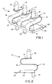
- each terminal is fabricated of a strip of conductive metal material having a short contact portion 14 and a long terminating portion 16.
- the short contact portion is fabricated of a relatively soft metal, as described hereinafter, drawn into a closed-ended cylindrical contact 18.
- Long terminating portion 16 is integral with contact portion 14 and is fabricated of a relatively hard tempered metal, as described hereinafter, formed into a generally S-shaped spring arm as shown clearly in Figures 1 and 2.
- each S-shaped spring arm 16 of each terminal 10 is generally planar for surface-mounting on a printed circuit board (not shown).
- overmolded dielectric base 20 includes a plurality of integrally molded mounting posts 24 depending from the underside thereof for insertion into appropriate mounting holes in the printed circuit board.
- terminal module 12 including the one-piece terminals 10, is shown mounted on a printed circuit board 26.
- Figure 6 shows distal ends 22 of the terminals surface mounted to a top surface 26a of the circuit board, with mounting posts 24 projecting through mounting holes 28 in the board.
- a chassis wall 30 is spaced from but fixed relative to printed circuit board 26.
- the chassis wall has a socket 32 with a through opening 34.
- the closed-ended cylindrical contacts 18, along with the top of the S-shaped spring arms 16 of terminals 10 project upwardly through openings 34 as best seen in Figure 6.
- An elastomeric sealing grommet 36 is press fit within socket 32 of chassis wall 30.
- the grommet has three holes 38 through which cylindrical contacts 18 of the terminals project. Therefore, the grommet seals with the cylindrical contacts within the peripheries of holes 38, and the grommet seals with the interior of socket 32 about the periphery of the grommet.
- the grommet seals the interior 40 of the enclosure from the exterior thereof.
- S-shaped spring arms 16 functioning to spring-load cylindrical contacts 18, the contacts can move in the direction of double-headed "A" (Fig. 6) within holes 38 in sealing grommet 36.
- the connector application shown in Figures 5 and 6 could be a battery connector assembly wherein the outside 42 of chassis wall 30 forms the battery side of the connector assembly, and terminals 10 form electrical interconnections between the battery terminals and circuit traces on printed circuit board 26.
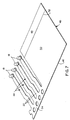
- Figure 7 illustrates how terminals 10 (Figs. 1-6) are fabricated from a plurality of strips, generally designated 44, stamped out of a continuous sheet of metal material, generally designated 46.
- the sheet can be a bi-metal sheet or a singular metal sheet. In either alternative, the sheet has a first portion 48 fabricated of a relatively soft material which can be deep drawn to form closed-ended cylindrical contacts 18.
- a second portion 50 of sheet 46 is fabricated of a relatively hard tempered material which can be formed into S-shaped spring arms 16. The two portions 48 and 50 are integrally joined, as at 52.
- first portion 48 can be fabricated of a copper material
- relatively hard second portion 50 can be fabricated of a phosphorus-bronze material, for instance.
- the two different metal portions are integrally joined by a laser weld at 52.
- the copper material of first portion 48 can be drawn into the closed-ended cylindrical contact configuration of contacts 18.
- the harder phosphorus-bronze material of second portion 50 can be formed into the S-shaped spring arms 16.
- sheet 46 also can be fabricated of a singular metal material such as of copper, brass or the like. With the singular material, second portion 50 of strip 46 is selectively treated by a strain hardening process so that the sheet is spring-hardened from edge 46a to line 52, leaving portion 48 in a softer state for drawing into contacts 18.
- a bi-metal sheet 46 or a singular metal sheet 46 With either a bi-metal sheet 46 or a singular metal sheet 46, the sheet is run through a series of stamping stations wherein strips 44 are stamped and contacts 18 are drawn, leaving distal ends 22 of the terminals still attached to a carrier strip 54 of the sheet material. The strips then are fed to forming stations whereat the S-shaped spring arms 16 are formed. When the terminals are severed from carrier strip 54, the terminals will have drawn contacts 18 and terminating distal ends 22 at opposite ends of the S-shaped arms. If the terminals are to be used in a terminal module, such as module 12 described above, three or more of the terminals may remain attached to carrier strip 54 while the terminals are fed to a molding station for overmolding dielectric base 20, whereafter carrier strip 54 can be removed.
Abstract
Description
Claims (23)
- A one-piece electrical terminal (10), comprising:strip (44) of conductive metal material having a short contact portion (14) and a long terminating portion (16),the short contact portion (14) being fabricated of a relatively soft metal drawn into a shaped contact (18), andthe long terminating portion being integral with the contact portion and being fabricated of a relatively hard tempered metal formed into a spring arm (16) supporting the contact (18).
- The one-piece electrical terminal of claim 1 wherein said contact portion (14) is drawn into a closed-ended cylindrical contact configuration (18).
- The one-piece electrical terminal of claim 1 wherein said terminating portion is formed into a generally S-shaped spring arm (16).
- The one-piece electrical terminal of claim 1 wherein a distal end (22) of said terminating portion (16) is generally planar for surface-mounting on a printed circuit board (26).
- The one-piece electrical terminal of claim 1 wherein said strip (44) is an integral bi-metal strip with said short contact portion (14) being of a relatively soft first metal integrally joined to the long terminating portion (16) which is of a relatively hard second metal.
- The one-piece electrical terminal of claim 1 wherein said strip (44) is fabricated of a singular metal material with the terminating portion (16) being selectively strain hardened.
- The one-piece electrical terminal of claim 6 wherein said strip (44) is fabricated of a copper material.
- The one-piece electrical terminal of claim 6 wherein said strip (44) is fabricated of a brass material.
- A one-piece electrical terminal (10), comprising:an elongated strip (44) of conductive metal material having a short contact end (14) and a long terminating end (16),the short contact end (14) being fabricated of a relatively soft metal drawn into a contact (18) having a closed-ended cylindrical configuration, andthe long terminating end (16) being integral with the contact end (14) and being fabricated of a relatively hard tempered metal formed into a generally S-shaped spring arm (16) supporting the contact (18).
- The one-piece electrical terminal of claim 9 wherein a distal end (22) of said terminating end (16) is generally planar for surface-mounting on a printed circuit board (26).
- The one-piece electrical terminal of claim 9 wherein said strip (44) is an integral bi-metal strip with said short contact end (14) being of a relatively soft first metal integrally joined to the long terminating end (16) which is of a relatively hard second metal.
- The one-piece electrical terminal of claim 9 wherein said strip (44) is fabricated of a singular metal material with the terminating end (16) being selectively strain hardened.
- The one-piece electrical terminal of claim 12 wherein said strip (44) is fabricated of a copper material.
- The one-piece electrical terminal of claim 12 wherein said strip (44) is fabricated of a brass material.
- The one-piece electrical terminal of claim 1 wherein said contact end (14) is fabricated of a copper material and said terminating end (16) is fabricated of a phosphorus-bronze material.
- A one-piece electrical terminal (10), comprising:a conductive metal structure (44) having first (14) and second (16) portions,the first portion (14) being fabricated of a relatively soft material drawn into a given shape (18), andthe second portion (16) being fabricated of a relatively hard tempered material formed into a spring configuration.
- The one-piece electrical terminal of claim 16 wherein said first portion (14) is drawn into a closed-ended cylindrical shape (18).
- The one-piece electrical terminal of claim 16 wherein said second portion (16) is formed into a generally S-shape.
- The one-piece electrical terminal of claim 16 wherein said structure (44) is fabricated of a singular metal material with the second portion (16) being selectively strain hardened.
- The one-piece electrical terminal of claim 19 wherein said structure (44) is fabricated of copper material.
- The one-piece electrical terminal of claim 19 wherein said structure (44) is fabricated of brass material.
- The one-piece electrical terminal of claim 19 wherein said structure (44) is an integral bi-metal structure with said first portion (14) being of a relatively soft first metal integrally joined to the second portion (16) which is of a relatively hard second metal.
- The one-piece electrical terminal of claim 22 wherein said first portion (14) is fabricated of a copper material and said second portion (16) is fabricated of a phosphorus-bronze material.
Applications Claiming Priority (2)
| Application Number | Priority Date | Filing Date | Title |
|---|---|---|---|
| US49489 | 1987-05-14 | ||
| US09/049,489 US5980335A (en) | 1998-03-27 | 1998-03-27 | Electrical terminal |
Publications (2)
| Publication Number | Publication Date |
|---|---|
| EP0945937A2 true EP0945937A2 (en) | 1999-09-29 |
| EP0945937A3 EP0945937A3 (en) | 2000-11-29 |
Family
ID=21960097
Family Applications (1)
| Application Number | Title | Priority Date | Filing Date |
|---|---|---|---|
| EP99106015A Withdrawn EP0945937A3 (en) | 1998-03-27 | 1999-03-25 | Electrical terminal |
Country Status (4)
| Country | Link |
|---|---|
| US (1) | US5980335A (en) |
| EP (1) | EP0945937A3 (en) |
| JP (1) | JP3154118B2 (en) |
| CN (1) | CN1230807A (en) |
Cited By (5)
| Publication number | Priority date | Publication date | Assignee | Title |
|---|---|---|---|---|
| EP1168514A1 (en) * | 2000-06-21 | 2002-01-02 | Japan Aviation Electronics Industry, Limited | Connector excellent in reliability of contact |
| EP1962384A3 (en) * | 2007-02-26 | 2010-06-16 | Gigaset Communications GmbH | Electromechanical contact system for very small mechanical contact forces |
| WO2015165914A1 (en) * | 2014-04-30 | 2015-11-05 | Conti Temic Microelectronic Gmbh | Contact element for an electric connection, copper strip for producing a plurality of contact elements |
| EP2922152A4 (en) * | 2012-11-13 | 2016-06-08 | Yazaki Corp | Connector |
| EP3723209A1 (en) * | 2015-09-08 | 2020-10-14 | Apple Inc. | Electrical contact structure |
Families Citing this family (52)
| Publication number | Priority date | Publication date | Assignee | Title |
|---|---|---|---|---|
| US6165002A (en) * | 1998-12-30 | 2000-12-26 | Garmin Corporation | Electrical connector apparatus |
| AU2001296280A1 (en) * | 2000-09-25 | 2002-04-08 | Avx Corporation | Electrical connector |
| US6497218B2 (en) * | 2001-02-28 | 2002-12-24 | Robert Bosch Corporation | Fuel injector module |
| ITMI20012837A1 (en) * | 2001-12-28 | 2003-06-28 | Abb Service Srl | METHOD FOR WELDING CONTACT PLATES AND CONTACT ELEMENTS OBTAINED BY SUCH METHOD |
| US6860769B2 (en) * | 2002-01-12 | 2005-03-01 | Taiwan Semiconductor Manufacturing Co., Ltd | Cathode contact pin for an electroplating process |
| ES2393269T3 (en) * | 2003-01-20 | 2012-12-19 | Connec Pty Limited | An electrical connector |
| US20070020960A1 (en) | 2003-04-11 | 2007-01-25 | Williams John D | Contact grid array system |
| US8584353B2 (en) | 2003-04-11 | 2013-11-19 | Neoconix, Inc. | Method for fabricating a contact grid array |
| US7244125B2 (en) | 2003-12-08 | 2007-07-17 | Neoconix, Inc. | Connector for making electrical contact at semiconductor scales |
| US7628617B2 (en) | 2003-06-11 | 2009-12-08 | Neoconix, Inc. | Structure and process for a contact grid array formed in a circuitized substrate |
| US7758351B2 (en) | 2003-04-11 | 2010-07-20 | Neoconix, Inc. | Method and system for batch manufacturing of spring elements |
| US7113408B2 (en) | 2003-06-11 | 2006-09-26 | Neoconix, Inc. | Contact grid array formed on a printed circuit board |
| US7056131B1 (en) | 2003-04-11 | 2006-06-06 | Neoconix, Inc. | Contact grid array system |
| US7114961B2 (en) | 2003-04-11 | 2006-10-03 | Neoconix, Inc. | Electrical connector on a flexible carrier |
| US7597561B2 (en) | 2003-04-11 | 2009-10-06 | Neoconix, Inc. | Method and system for batch forming spring elements in three dimensions |
| US7070419B2 (en) * | 2003-06-11 | 2006-07-04 | Neoconix Inc. | Land grid array connector including heterogeneous contact elements |
| JP2005050738A (en) * | 2003-07-31 | 2005-02-24 | Jst Mfg Co Ltd | Electric connector |
| US20050051138A1 (en) * | 2003-09-08 | 2005-03-10 | Robert Bosch Corporation | Intake manifold assembly |
| US7347698B2 (en) | 2004-03-19 | 2008-03-25 | Neoconix, Inc. | Deep drawn electrical contacts and method for making |
| US7090503B2 (en) | 2004-03-19 | 2006-08-15 | Neoconix, Inc. | Interposer with compliant pins |
| TWI309094B (en) | 2004-03-19 | 2009-04-21 | Neoconix Inc | Electrical connector in a flexible host and method for fabricating the same |
| US7025601B2 (en) | 2004-03-19 | 2006-04-11 | Neoconix, Inc. | Interposer and method for making same |
| US7695053B1 (en) * | 2004-04-16 | 2010-04-13 | Bae Systems Survivability Systems, Llc | Lethal threat protection system for a vehicle and method |
| US7354276B2 (en) | 2004-07-20 | 2008-04-08 | Neoconix, Inc. | Interposer with compliant pins |
| EP1778520B1 (en) * | 2004-08-09 | 2015-08-05 | Delphi Technologies Inc. | Child restraint system comprising event data recorder, and method for providing data relating to installation or adjustment |
| US7410212B2 (en) * | 2004-09-08 | 2008-08-12 | Delphi Technologies, Inc. | Child restraint system |
| CN100555752C (en) * | 2005-09-16 | 2009-10-28 | 鸿富锦精密工业(深圳)有限公司 | Arrangement for resilient contacting and use the electronic equipment of this arrangement for resilient contacting |
| US7357644B2 (en) | 2005-12-12 | 2008-04-15 | Neoconix, Inc. | Connector having staggered contact architecture for enhanced working range |
| US20080124978A1 (en) * | 2006-11-29 | 2008-05-29 | Lotes Co., Ltd. | Electrical connector |
| DE102007012500A1 (en) * | 2007-03-15 | 2008-09-18 | Continental Automotive Gmbh | Contacting device for contacting circuit boards comprises electrical conductors coupled with an electrically insulating coupling body so that the ends of the conductors protrude from the coupling body |
| EP2058867A3 (en) * | 2007-11-12 | 2009-07-22 | Multi-Holding AG | Junction box for a photovoltaic solar panel |
| CN101472203A (en) * | 2007-12-27 | 2009-07-01 | 深圳富泰宏精密工业有限公司 | Electronic device |
| CN101588395A (en) * | 2008-05-21 | 2009-11-25 | 深圳富泰宏精密工业有限公司 | Electronic device with loudspeaker |
| DE102010014980A1 (en) * | 2010-04-14 | 2011-10-20 | Pfisterer Kontaktsysteme Gmbh | Electrical plug connection element and plug connection part with a plurality of plug connection elements |
| KR101817804B1 (en) * | 2011-08-03 | 2018-01-11 | 삼성전자주식회사 | Contact terminal |
| JP5718203B2 (en) * | 2011-10-05 | 2015-05-13 | 富士通コンポーネント株式会社 | Socket module and socket |
| US8641428B2 (en) | 2011-12-02 | 2014-02-04 | Neoconix, Inc. | Electrical connector and method of making it |
| JP5943647B2 (en) * | 2012-02-29 | 2016-07-05 | 日本航空電子工業株式会社 | Electrical connector |
| US9680273B2 (en) | 2013-03-15 | 2017-06-13 | Neoconix, Inc | Electrical connector with electrical contacts protected by a layer of compressible material and method of making it |
| US9614313B2 (en) | 2013-08-29 | 2017-04-04 | Japan Aviation Electronics Industry, Ltd. | Electrical connector having a contact with a fixing part press-fitted within a housing |
| JP6257253B2 (en) * | 2013-10-07 | 2018-01-10 | 日本航空電子工業株式会社 | connector |
| JP6108462B2 (en) * | 2013-10-18 | 2017-04-05 | 日本航空電子工業株式会社 | connector |
| KR102118176B1 (en) * | 2013-12-13 | 2020-06-09 | 삼성전자주식회사 | Contact Clip for Electric Apparatus and Electric Apparatus Comprising the Same |
| US10579097B2 (en) | 2015-09-04 | 2020-03-03 | Apple Inc. | Electronic device with contacts flush with housing |
| US9778705B2 (en) | 2015-09-04 | 2017-10-03 | Apple Inc. | Electronic device with moveable contacts at an exterior surface |
| US10224661B2 (en) | 2015-09-08 | 2019-03-05 | Apple Inc. | Low-profile spring-loaded contacts |
| US9948018B2 (en) | 2015-09-08 | 2018-04-17 | Apple Inc. | Low-profile power and data contacts |
| KR101947440B1 (en) * | 2016-02-04 | 2019-05-10 | 주식회사 아모텍 | Clip type contactor and protection device having the same |
| US9985369B1 (en) * | 2016-02-26 | 2018-05-29 | Arista Networks, Inc. | Method and apparatus to mitigate assembly torsion |
| DE102016014986A1 (en) * | 2016-12-15 | 2018-06-21 | e.solutions GmbH | Electrical connection element, docking station and vehicle |
| US10707627B2 (en) | 2017-09-29 | 2020-07-07 | Apple Inc. | Hybrid connector |
| US20230087891A1 (en) * | 2021-09-23 | 2023-03-23 | Apple Inc. | Pass-through connectors for connector systems |
Citations (4)
| Publication number | Priority date | Publication date | Assignee | Title |
|---|---|---|---|---|
| US3975076A (en) * | 1972-12-06 | 1976-08-17 | Matsushita Electric Industrial Co., Ltd. | Receptacle for printed circuit board |
| US5511996A (en) * | 1994-11-14 | 1996-04-30 | A.W. Industries, Inc. | Connector contact and method |
| EP0767514A1 (en) * | 1995-10-05 | 1997-04-09 | Itt Manufacturing Enterprises, Inc. | One-piece hooded socket contact and method of producing same |
| WO1997045900A1 (en) * | 1996-05-31 | 1997-12-04 | The Whitaker Corporation | Rechargeable battery connector |
Family Cites Families (7)
| Publication number | Priority date | Publication date | Assignee | Title |
|---|---|---|---|---|
| US4413874A (en) * | 1981-02-27 | 1983-11-08 | Williams Robert A | Multiple contact testing device |
| US4778404A (en) * | 1983-12-27 | 1988-10-18 | Amp Incorporated | Spring terminal |
| US5350322A (en) * | 1990-02-22 | 1994-09-27 | Yazaki Corporation | Bulb socket terminal |
| US5151643A (en) * | 1991-03-04 | 1992-09-29 | Motorola, Inc. | Integral hang-up and battery charging apparatus |
| WO1994011925A1 (en) * | 1992-11-11 | 1994-05-26 | Elco Europe Limited | Electrical connector |
| US5664973A (en) * | 1995-01-05 | 1997-09-09 | Motorola, Inc. | Conductive contact |
| US5713765A (en) * | 1996-04-23 | 1998-02-03 | Nugent; Steven F. | High-current audio connector |
-
1998
- 1998-03-27 US US09/049,489 patent/US5980335A/en not_active Expired - Fee Related
-
1999
- 1999-03-17 JP JP07220899A patent/JP3154118B2/en not_active Expired - Fee Related
- 1999-03-25 EP EP99106015A patent/EP0945937A3/en not_active Withdrawn
- 1999-03-26 CN CN99104429A patent/CN1230807A/en active Pending
Patent Citations (4)
| Publication number | Priority date | Publication date | Assignee | Title |
|---|---|---|---|---|
| US3975076A (en) * | 1972-12-06 | 1976-08-17 | Matsushita Electric Industrial Co., Ltd. | Receptacle for printed circuit board |
| US5511996A (en) * | 1994-11-14 | 1996-04-30 | A.W. Industries, Inc. | Connector contact and method |
| EP0767514A1 (en) * | 1995-10-05 | 1997-04-09 | Itt Manufacturing Enterprises, Inc. | One-piece hooded socket contact and method of producing same |
| WO1997045900A1 (en) * | 1996-05-31 | 1997-12-04 | The Whitaker Corporation | Rechargeable battery connector |
Cited By (10)
| Publication number | Priority date | Publication date | Assignee | Title |
|---|---|---|---|---|
| EP1168514A1 (en) * | 2000-06-21 | 2002-01-02 | Japan Aviation Electronics Industry, Limited | Connector excellent in reliability of contact |
| US6524140B2 (en) | 2000-06-21 | 2003-02-25 | Japan Aviation Electronics Industry, Ltd. | Connector excellent in reliability of contact |
| EP1962384A3 (en) * | 2007-02-26 | 2010-06-16 | Gigaset Communications GmbH | Electromechanical contact system for very small mechanical contact forces |
| EP2922152A4 (en) * | 2012-11-13 | 2016-06-08 | Yazaki Corp | Connector |
| US9531100B2 (en) | 2012-11-13 | 2016-12-27 | Yazaki Corporation | Connector |
| WO2015165914A1 (en) * | 2014-04-30 | 2015-11-05 | Conti Temic Microelectronic Gmbh | Contact element for an electric connection, copper strip for producing a plurality of contact elements |
| CN106463853A (en) * | 2014-04-30 | 2017-02-22 | 大陆泰密克微电子有限责任公司 | Contact element for an electric connection, copper strip for producing a plurality of contact elements |
| US9991618B2 (en) | 2014-04-30 | 2018-06-05 | Conti Temic Microelectronic Gmbh | Contact element for an electrical connection |
| CN106463853B (en) * | 2014-04-30 | 2020-02-14 | 大陆泰密克微电子有限责任公司 | Contact element for electrical connection, copper strip for producing a large number of contact elements |
| EP3723209A1 (en) * | 2015-09-08 | 2020-10-14 | Apple Inc. | Electrical contact structure |
Also Published As
| Publication number | Publication date |
|---|---|
| EP0945937A3 (en) | 2000-11-29 |
| CN1230807A (en) | 1999-10-06 |
| JPH11329634A (en) | 1999-11-30 |
| JP3154118B2 (en) | 2001-04-09 |
| US5980335A (en) | 1999-11-09 |
Similar Documents
| Publication | Publication Date | Title |
|---|---|---|
| US5980335A (en) | Electrical terminal | |
| US10756466B2 (en) | Connector | |
| EP0590517B1 (en) | Electrical connector with preloaded spring-like terminal with improved wiping action | |
| US6520812B1 (en) | Connector terminal with resilient contacts | |
| US7029287B2 (en) | Electrical connector in which a wiping action is carried out in a narrow area | |
| CA2156465C (en) | Clip and method therefor | |
| US5788539A (en) | Surface mountable electrical connector | |
| US6574855B1 (en) | Method of making a switch-equipped coaxial connector | |
| US6540529B1 (en) | Electrical connector assembly | |
| WO2002035662A1 (en) | Filtered electrical connector | |
| US5904580A (en) | Elastomeric connector having a plurality of fine pitched contacts, a method for connecting components using the same and a method for manufacturing such a connector | |
| US20030100229A1 (en) | Method for forming an electrical connector and an electrical connector obtained thereby | |
| EP0866528A1 (en) | Electrical connector with tool engagement arm | |
| EP0631344A2 (en) | Sealed insulation displacement connector | |
| US6599140B1 (en) | Electrical connector assembly having a placement member | |
| EP1061608A3 (en) | Board to board electrical connectors | |
| KR20040103766A (en) | Electrical connector and method of producing the same | |
| EP0047095A2 (en) | A connector for a leadless electronic package | |
| EP1009075A3 (en) | Electrical contact and bandolier assembly | |
| US6336820B2 (en) | Switch-equipped coaxial connector | |
| JPH06260238A (en) | Connecting terminal | |
| EP1453143A2 (en) | Electrical connector having a holddown for ground connection | |
| US6109932A (en) | Three-dimensional electrical interconnection system | |
| US6257903B1 (en) | Self-docking electrical connector | |
| CN218958052U (en) | Belt buckle terminal |
Legal Events
| Date | Code | Title | Description |
|---|---|---|---|
| PUAI | Public reference made under article 153(3) epc to a published international application that has entered the european phase |
Free format text: ORIGINAL CODE: 0009012 |
|
| AK | Designated contracting states |
Kind code of ref document: A2 Designated state(s): DE FR GB IT |
|
| AX | Request for extension of the european patent |
Free format text: AL;LT;LV;MK;RO;SI |
|
| PUAL | Search report despatched |
Free format text: ORIGINAL CODE: 0009013 |
|
| AK | Designated contracting states |
Kind code of ref document: A3 Designated state(s): AT BE CH CY DE DK ES FI FR GB GR IE IT LI LU MC NL PT SE |
|
| AX | Request for extension of the european patent |
Free format text: AL;LT;LV;MK;RO;SI |
|
| 17P | Request for examination filed |
Effective date: 20010522 |
|
| AKX | Designation fees paid |
Free format text: DE FR GB IT |
|
| STAA | Information on the status of an ep patent application or granted ep patent |
Free format text: STATUS: THE APPLICATION HAS BEEN WITHDRAWN |
|
| 18W | Application withdrawn |
Effective date: 20021210 |