EP0949961B2 - Process and reactor for carrying out an exothermic reaction - Google Patents
Process and reactor for carrying out an exothermic reaction Download PDFInfo
- Publication number
- EP0949961B2 EP0949961B2 EP97937577A EP97937577A EP0949961B2 EP 0949961 B2 EP0949961 B2 EP 0949961B2 EP 97937577 A EP97937577 A EP 97937577A EP 97937577 A EP97937577 A EP 97937577A EP 0949961 B2 EP0949961 B2 EP 0949961B2
- Authority
- EP
- European Patent Office
- Prior art keywords
- zone
- slurry
- catalyst particles
- freeboard
- trap
- Prior art date
- Legal status (The legal status is an assumption and is not a legal conclusion. Google has not performed a legal analysis and makes no representation as to the accuracy of the status listed.)
- Expired - Lifetime
Links
Images


Classifications
-
- B—PERFORMING OPERATIONS; TRANSPORTING
- B01—PHYSICAL OR CHEMICAL PROCESSES OR APPARATUS IN GENERAL
- B01J—CHEMICAL OR PHYSICAL PROCESSES, e.g. CATALYSIS OR COLLOID CHEMISTRY; THEIR RELEVANT APPARATUS
- B01J8/00—Chemical or physical processes in general, conducted in the presence of fluids and solid particles; Apparatus for such processes
- B01J8/18—Chemical or physical processes in general, conducted in the presence of fluids and solid particles; Apparatus for such processes with fluidised particles
- B01J8/1836—Heating and cooling the reactor
-
- B—PERFORMING OPERATIONS; TRANSPORTING
- B01—PHYSICAL OR CHEMICAL PROCESSES OR APPARATUS IN GENERAL
- B01J—CHEMICAL OR PHYSICAL PROCESSES, e.g. CATALYSIS OR COLLOID CHEMISTRY; THEIR RELEVANT APPARATUS
- B01J8/00—Chemical or physical processes in general, conducted in the presence of fluids and solid particles; Apparatus for such processes
- B01J8/005—Separating solid material from the gas/liquid stream
- B01J8/0065—Separating solid material from the gas/liquid stream by impingement against stationary members
-
- B—PERFORMING OPERATIONS; TRANSPORTING
- B01—PHYSICAL OR CHEMICAL PROCESSES OR APPARATUS IN GENERAL
- B01J—CHEMICAL OR PHYSICAL PROCESSES, e.g. CATALYSIS OR COLLOID CHEMISTRY; THEIR RELEVANT APPARATUS
- B01J8/00—Chemical or physical processes in general, conducted in the presence of fluids and solid particles; Apparatus for such processes
- B01J8/18—Chemical or physical processes in general, conducted in the presence of fluids and solid particles; Apparatus for such processes with fluidised particles
- B01J8/20—Chemical or physical processes in general, conducted in the presence of fluids and solid particles; Apparatus for such processes with fluidised particles with liquid as a fluidising medium
- B01J8/22—Chemical or physical processes in general, conducted in the presence of fluids and solid particles; Apparatus for such processes with fluidised particles with liquid as a fluidising medium gas being introduced into the liquid
- B01J8/224—Chemical or physical processes in general, conducted in the presence of fluids and solid particles; Apparatus for such processes with fluidised particles with liquid as a fluidising medium gas being introduced into the liquid the particles being subject to a circulatory movement
- B01J8/226—Chemical or physical processes in general, conducted in the presence of fluids and solid particles; Apparatus for such processes with fluidised particles with liquid as a fluidising medium gas being introduced into the liquid the particles being subject to a circulatory movement internally, i.e. the particles rotate within the vessel
-
- C—CHEMISTRY; METALLURGY
- C08—ORGANIC MACROMOLECULAR COMPOUNDS; THEIR PREPARATION OR CHEMICAL WORKING-UP; COMPOSITIONS BASED THEREON
- C08F—MACROMOLECULAR COMPOUNDS OBTAINED BY REACTIONS ONLY INVOLVING CARBON-TO-CARBON UNSATURATED BONDS
- C08F10/00—Homopolymers and copolymers of unsaturated aliphatic hydrocarbons having only one carbon-to-carbon double bond
-
- C—CHEMISTRY; METALLURGY
- C10—PETROLEUM, GAS OR COKE INDUSTRIES; TECHNICAL GASES CONTAINING CARBON MONOXIDE; FUELS; LUBRICANTS; PEAT
- C10G—CRACKING HYDROCARBON OILS; PRODUCTION OF LIQUID HYDROCARBON MIXTURES, e.g. BY DESTRUCTIVE HYDROGENATION, OLIGOMERISATION, POLYMERISATION; RECOVERY OF HYDROCARBON OILS FROM OIL-SHALE, OIL-SAND, OR GASES; REFINING MIXTURES MAINLY CONSISTING OF HYDROCARBONS; REFORMING OF NAPHTHA; MINERAL WAXES
- C10G2/00—Production of liquid hydrocarbon mixtures of undefined composition from oxides of carbon
- C10G2/30—Production of liquid hydrocarbon mixtures of undefined composition from oxides of carbon from carbon monoxide with hydrogen
- C10G2/32—Production of liquid hydrocarbon mixtures of undefined composition from oxides of carbon from carbon monoxide with hydrogen with the use of catalysts
- C10G2/34—Apparatus, reactors
- C10G2/342—Apparatus, reactors with moving solid catalysts
-
- B—PERFORMING OPERATIONS; TRANSPORTING
- B01—PHYSICAL OR CHEMICAL PROCESSES OR APPARATUS IN GENERAL
- B01J—CHEMICAL OR PHYSICAL PROCESSES, e.g. CATALYSIS OR COLLOID CHEMISTRY; THEIR RELEVANT APPARATUS
- B01J2208/00—Processes carried out in the presence of solid particles; Reactors therefor
- B01J2208/00008—Controlling the process
- B01J2208/00017—Controlling the temperature
- B01J2208/00106—Controlling the temperature by indirect heat exchange
- B01J2208/00115—Controlling the temperature by indirect heat exchange with heat exchange elements inside the bed of solid particles
- B01J2208/00141—Coils
-
- Y—GENERAL TAGGING OF NEW TECHNOLOGICAL DEVELOPMENTS; GENERAL TAGGING OF CROSS-SECTIONAL TECHNOLOGIES SPANNING OVER SEVERAL SECTIONS OF THE IPC; TECHNICAL SUBJECTS COVERED BY FORMER USPC CROSS-REFERENCE ART COLLECTIONS [XRACs] AND DIGESTS
- Y02—TECHNOLOGIES OR APPLICATIONS FOR MITIGATION OR ADAPTATION AGAINST CLIMATE CHANGE
- Y02P—CLIMATE CHANGE MITIGATION TECHNOLOGIES IN THE PRODUCTION OR PROCESSING OF GOODS
- Y02P20/00—Technologies relating to chemical industry
- Y02P20/50—Improvements relating to the production of bulk chemicals
- Y02P20/584—Recycling of catalysts
Definitions
- the present invention relates to a process for carrying out an exothermic reaction in the presence of a solid catalyst in a three-phase slurry reactor. According to a further aspect, the present invention relates to a three-phase slurry reactor for carrying out an exothermic reaction.
- the said reactor comprises a slurry zone and a freeboard zone.
- the freeboard zone is located within the reactor, above the slurry zone.
- solid catalyst particles are kept in suspension in a liquid.
- the liquid serves as heat-transfer medium.
- the mixture of catalyst particles and liquid is commonly referred to as slurry.
- One or more gaseous reactants bubble through the slurry zone.
- the freeboard zone located above the slurry zone contains substantially no slurry and serves as a disengagement zone between slurry, and gaseous products and reactants.
- the catalyst particles are typically kept in suspension by stirring or agitation by a mechanical device or, preferably, by an upward gas and/or liquid velocity.
- catalyst particles is intended as reference to catalyst particles per se and/or any fines thereof.
- the present invention relates to a process according to claim 1.
- the exothermic reaction produces at least some gaseous products, which gaseous products are capable of at least partly condensing at a temperature between the reaction temperature in the top part of the slurry zone and 50 °C below the said reaction temperature, and the liquid reflux is generated and maintained by at least partly condensing the gaseous product in the freeboard zone.
- the gaseous products may at least partly be condensed by means known to those skilled in the art.
- the gaseous products are at least partly condensed by indirect cooling means in the freeboard zone.
- indirect cooling means may be applied, including indirect cooling means such as cooling coils.
- the cooling means in the freeboard zone is preferably controllable independent from the cooling means present in the slurry zone.
- direct cooling means refers to those means where the cooling medium is in direct contact with the slurry in the slurry zone.
- Indirect cooling means refers to those means where the cooling medium is not in direct contact with the slurry in the slurry zone.
- An example of the latter is an arrangement of cooling tubes immersed in the slurry.
- any indirect cooling means used to cool the slurry zone hereinafter indirect slurry cooling means, substantially do not extend into the freeboard zone.
- the average temperature in the freeboard zone is decreased to a temperature which is up to 50 °C lower than the temperature in the top of the slurry zone.
- the temperature in the top of the slurry zone is typically the average temperature prevailing at about 5 to 15 cm below the interface between the slurry zone and the freeboard zone. More preferably, the decrease is up to 30 °C.
- the temperature in the freeboard zone is preferably decreased by at least 5 °C, more preferably at least 10 °C, relative to the temperature in the top of the slurry zone.
- the desired temperature decrease depends on a variety of factors such as the quantity of condensing product at a certain temperature; the amount of catalyst particles, or fines thereof, which is present in the freeboard zone; the complexity of, and volume occupied by, internals in the freeboard zone; and the average particle size of catalyst particles or fines present in the freeboard zone.
- the average particle size of the catalyst particles may vary between wide limits, depending inter alia on the type of slurry zone regime. Typically, the average particle size may range from 1 ⁇ m to 2 mm, preferably from 1 ⁇ m to 1 mm.
- the slurry zone regime is commonly referred to as an ebullating bed regime.
- the average particle size in an ebullating bed regime is less than 600 ⁇ m, more preferably in the range from 100 to 400 ⁇ m. It will be appreciated that in general the larger the particle size of a particle, the smaller the chance that particle escapes from the slurry zone into the freeboard zone. Thus, if an ebullating bed regime is employed, primarily fines of catalyst particles will escape to the freeboard zone.
- the slurry zone regime is commonly referred to as a slurry phase regime.
- the average particle size in a slurry phase regime is more than 5 ⁇ m, more preferably in the range from 10 to 75 ⁇ m.
- the slurry zone regime is commonly referred to as stirred tank regime. It will be appreciated that in principle any average particle size within the above ranges can be applied. Preferably, the average particle size is kept in the range from 1 to 200 ⁇ m.
- the concentration of catalyst particles present in the slurry may range from 5 to 45% by volume, preferably, from 10 to 35% by volume. It may be desired to add in addition other particles to the slurry, as set out in for example European patent application publication No. 0 450 859 .
- the total concentration of solid particles in the slurry is typically not more than 50% by volume, preferably not more than 45% by volume.
- Suitable slurry liquids are known to those skilled in the art. Typically, at least a part of the slurry liquid is a reaction product of the exothermic reaction. Preferably, the slurry liquid is substantially completely a reaction product.
- the exothermic reaction is a reaction which is carried out in the presence of a solid catalyst, and which is capable of being carried out in a three-phase slurry reactor. Typically, at least one of the reactants of the exothermic reaction is gaseous. Examples of exothermic reactions include hydrogenation reactions, hydroformylation, alkanol synthesis, the preparation of aromatic urethanes using carbon monoxide, Kölbel-Engelhardt synthesis, polyolefin synthesis, and Fischer-Tropsch synthesis. According to a preferred embodiment of the present invention, the exothermic reaction is a Fischer-Tropsch synthesis reaction.
- Fischer-Tropsch synthesis is well known to those skilled in the art and involves synthesis of hydrocarbons from a gaseous mixture of hydrogen and carbon monoxide, by contacting that mixture at reaction conditions with a Fischer-Tropsch catalyst.
- Products of the Fischer-Tropsch synthesis may range from methane to heavy paraffinic waxes.
- the production of methane is minimised and a substantial portion of the hydrocarbons produced have a carbon chain length of at least 5 carbon atoms.
- the amount of C5+ hydrocarbons is at least 60% by weight of the total product, more preferably, at least 70% by weight, even more preferably at least 80% by weight, most preferably at least 85% by weight.
- Fischer-Tropsch catalysts are known in the art, and typically include a Group VIII metal component, preferably cobalt, iron and/or ruthenium, more preferably cobalt.
- the catalysts comprise a catalyst carrier.
- the catalyst carrier is preferably porous, such as a porous inorganic refractory oxide, more preferably alumina, silica, titania, zirconia or mixtures thereof.
- the optimum amount of catalytically active metal present on the carrier depends inter alia on the specific catalytically active metal.
- the amount of cobalt present in the catalyst may range from 1 to 100 parts by weight per 100 parts by weight of carrier material, preferably from 10 to 50 parts by weight per 100 parts by weight of carrier material.
- the catalytically active metal may be present in the catalyst together with one or more metal promoters or cocatalysts.
- the promoters may be present as metals or as the metal oxide, depending upon the particular promoter concerned. Suitable promoters include oxides of metals from Groups IIA, IIIB, IVB, VB, VIB and/or VIIB of the Periodic Table, oxides of the lanthanides and/or the actinides.
- the catalyst comprises at least one oxide of an element in Group IVB, VB and/or VIIB of the Periodic Table, in particular titanium, zirconium, manganese and/or vanadium.
- the catalyst may comprise a metal promoter selected from Groups VIIB and/or VIII of the Periodic Table. Preferred metal promoters include rhenium, platinum and palladium.
- a most suitable catalyst comprises cobalt as the catalytically active metal and zirconium as a promoter.
- Another most suitable catalyst comprises cobalt as the catalytically active metal and manganese and/or vanadium as a promoter.
- the promoter if present in the catalyst, is typically present in an amount of from 0.1 to 60 parts by weight per 100 parts by weight of carrier material, preferably from 0.5 to 40 parts by weight per 100 parts by weight of carrier material. It will however be appreciated that the optimum amount of promoter may vary for the respective elements which act as promoter. If the catalyst comprises cobalt as the catalytically active metal and manganese and/or vanadium as promoter, the cobalt : (manganese + vanadium) atomic ratio is advantageously at least 12:1.
- the Fischer-Tropsch synthesis is preferably carried out at a temperature in the range from 125 to 350 °C, more preferably 175 to 275 °C, most preferably 200 to 260 °C.
- the pressure preferably ranges from 5 to 150 bar abs., more preferably from 5 to 80 bar abs.
- Hydrogen and carbon monoxide (synthesis gas) is typically fed to the three-phase slurry reactor at a molar ratio in the range from 0.4 to 2.5.
- the hydrogen to carbon monoxide molar ratio is in the range from 1.0 to 2.5.
- the gaseous hourly space velocity may vary within wide ranges and is typically in the range from 1500 to 10000 Nl/l/h, preferably in the range from 2500 to 7500 Nl/l/h.
- the Fischer-Tropsch synthesis is preferably carried out in a slurry phase regime or an ebullating bed regime, wherein the catalyst particles are kept in suspension by an upward superficial gas and/or liquid velocity.
- the superficial liquid velocity is kept in the range from 0.001 to 4.0 cm/sec, including liquid production. It will be appreciated that the preferred range may depend on the preferred mode of operation. According to one preferred embodiment, the superficial liquid velocity is kept in the range from 0.005 to 1.0 cm/sec.
- the volume of the freeboard zone occupied by internals is minimised. In this way, the chance that a catalyst particle escaping from the slurry zone sticks to an internal in the freeboard zone, is minimised as well.
- the freeboard zone contains means specifically designed to trap catalyst particles.
- Such means e.g. may be used for protecting parts of the freeboard zone which are difficult to clean with a liquid reflux or otherwise, for example outlet means for gases.
- the means to trap catalyst particles will allow relatively easy passage of gases whereas catalyst particles, and/or fines thereof, and any liquid droplets entrained with such gases are trapped. Further, the means to trap catalyst particles will allow relatively easy removal of catalyst particles, and liquid droplets, by a liquid reflux.
- the means to trap catalyst particles typically comprises one or more means which divert the passage of gases.
- the gases are forced to follow a tortuous path.
- any catalyst particles collide with the means to divert the passage of gases.
- a liquid reflux is maintained to remove the said catalyst particles.
- the means to trap catalyst particles comprises one or more, in particular a plurality of, corrugated plates.
- Each corrugated plate contains at least one corrugation, preferably a plurality of corrugations.
- the corrugations define crests and troughs on the corrugated plate.
- the corrugated plates are placed substantially vertical in the freeboard zone, and preferably substantially parallel to the overall direction of flow of the gases through the trap. The crests of the corrugations, however, are placed in such direction to the overall direction of flow of the gases through the trap, that the gases are forced to follow a tortuous path through the trap.
- the degree of tortuosity may be defined as the ratio between the actual path length through the means to trap catalyst particles and a hypothetical shortest path length along a straight line.
- the said ratio is typically greater than 1:1, preferably at least 1.1:1, more preferably at least 1.2:1.
- the said ratio is not greater than 2:1, preferably not greater than 1.5:1.
- the angle between the direction of the crests and the overall direction of flow of the gases through the trap is typically at least 30°, preferably at least 60°, more preferably substantially 90°.
- the flow of gases in the freeboard zone is normally substantially vertical.
- the means to trap catalyst particles is arranged such that the overall direction of flow of gases through the trap is substantially vertical as well. This allows a relatively simple construction. It will however be appreciated that a disadvantage of a substantially vertical (upward) flow of gases through the trap is that removal of catalyst with a substantially vertical (downward) liquid reflux may be difficult at relatively high gas velocities.
- the trap is arranged such that the direction of flow of gases through the trap makes an angle of less than 180°, but more than 0°, with the direction of flow of the liquid reflux.
- the angle ranges from 30° to 150°, in particular the angle is substantially 90°.
- the direction of flow of gas through the means to trap catalyst particles is substantially horizontal, and the liquid reflux is substantial vertical.
- the liquid reflux over the means to trap catalyst particles may be generated and maintained in the same way as described above.
- the trap is cooled to generate a reflux of condensed gaseous product.
- the trap comprises cooling means.
- corrugated plates may be connected with one or more cooling tubes.
- the liquid reflux over the trap is maintained by spraying liquid from an external source over the trap.
- the corrugations on the corrugated plates may be shaped in a large number of ways.
- the corrugations may have the shape of a sine wave, a sawtooth wave, a triangular wave, a half- or full-wave rectified sine wave or combinations thereof.
- the corrugations preferably do not have the shape of a square wave.
- the shape of the corrugations is substantially constant across a corrugated plate, and the corrugated plates preferably have substantially the same size and shape.
- the corrugated plates are arranged substantially in parallel.
- the space between the plates defines the passage for the gases.
- the corrugated plates are arranged such that the width of the passage remains substantially constant.
- the space between two corrugated plates is preferably in the range from 1 to 10 mm, more preferably from 2 to 5 mm.
- the pressure drop between gas inlet and gas outlet of the trap is typically less than 2 bar, preferably less than 0.1 bar. Generally, the pressure drop will be more than 0.01 bar.
- the present invention relates to a three phase slurry reactor for carrying out exothermic reactions in the presence of a catalyst, according to claim 3.
- the three-phase slurry reactor is specifically adapted to the process of the present invention.
- preferred embodiments discussed in relation to the process are also preferred embodiments with respect to the three-phase slurry reactor.
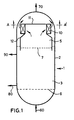
- Figure 1 schematically depicts a vertical cross-section through a three-phase slurry reactor 1 comprising a freeboard zone 5, which zone comprises a trap for catalyst particles 10, wherein the flow of gases through the trap is substantially horizontal and the liquid reflux is substantially vertical.
- Figure 2 schematically depicts a horizontal cross-section through the three-phase slurry reactor 1 along the line A-A', when looking in the direction of the arrow, as shown in Figure 1 .
- Figure 3 schematically depicts in more detail than in Figure 1 the part of the three-phase slurry reactor 1 containing the trap for catalyst particles 10.
- Figure 3 schematically depicts a vertical cross-section along the line B-B' as shown in Figure 2 .
- Figure 4 schematically depicts a corrugated plate of a trap for catalyst particles.
- Figure 1 depicts a three-phase slurry reactor 1, comprising a reactor wall 2 enclosing a slurry zone 3 and a freeboard zone 5.
- a sheet 6 defines the bottom end of the slurry zone 3.
- Dashed line 7 depicts the interface between the slurry zone 3 and the freeboard zone 5.
- the reactor 1 is equipped with gas inlet means 60 and gas outlet means 70, slurry inlet means 80 and slurry outlet means 90.
- Sheet 6 allows passage of gas from gas inlet means 60 to the slurry zone 3.
- the slurry zone 3 is equipped with cooling tubes (not shown), which cooling tubes do not extend into the freeboard zone 5.
- the freeboard zone 5 is equipped with means to trap catalyst particles (trap) 10.
- the trap 10 contains a plurality of substantially vertical corrugates plates.
- the corrugated plates are arranged substantially parallel to each other, and substantially parallel to the overall direction of flow of gasses through trap 10.
- the corrugated plates may be contained in a circular housing, but typically, the corrugated plates are contained in two or more, preferably four or six, discrete rectangular housings, as depicted in Figure 2 .
- Sheet 11 forces gases to flow substantially horizontal through the trap 10.
- Sheet 11 and trap 10 are cooled by cooling tubes as shown in Figures 2 and 3 .
- catalyst particles are removed from sheet 11 and trap 10 by a liquid reflux.
- Catalyst particles removed from trap 10 by a liquid reflux are returned to the slurry zone 3 by tube 12.
- the outlet of tube 12 is immersed in the slurry zone 3.
- reference number 2 depicts the reactor wall of a three-phase slurry reactor 1.
- Six traps for catalyst particles 10 have been mounted on sheet 11.
- Each trap 10 contains a gas inlet 13 and a gas outlet 14.
- Gas outlet 14 is in fluid communication with hole 15 in sheet 11.
- Gas entering trap 10 is forced to follow a tortuous path along a plurality of corrugated plates 16.
- corrugated plates 16 are cooled by means of cooling tubes 20. Cooling tubes 20 connect to a header (not shown) in the zone above sheet 11 (see Figure 3 ), and, preferably, is independent from the cooling system in the slurry zone 3.
- Figure 3 depicts a trap for catalyst particles 10. Catalyst particles removed from trap 10 by a liquid reflux, are returned to the slurry zone 3 by tube 12. Due to the pressure drop over the trap 10 between gas inlet 13 and gas outlet 14, the interface level between slurry zone 3 and freeboard zone 5 in tube 12 will be somewhat higher than the level in the reactor, as indicated by dashed line 7.
- corrugated plates 16 are cooled by means of cooling tubes 20.
- the cooling tubes are typically U-shaped. One end of the cooling tube 20 connects in fluid communication to coolant inlet tube 25, whereas the other end of cooling tube 20 connects in fluid communication to coolant outlet tube 30.
- Coolant inlet tube 25 connects in fluid communication to coolant inlet distribution ring 35, and coolant outlet tube 30 connects in fluid communication to coolant outlet distribution ring 40.
- Distribution ring 35 connects in fluid communication to inlet means for introducing coolant into the reactor (not shown) and distribution ring 40 connects in fluid communication to outlet means for removing coolant from the reactor (not shown).
- Suitable coolants are known to those skilled in the art.
- a preferred coolant is water and/or steam.
- Figure 4 schematically depicts a corrugated plate 50 for use in a trap for catalyst particles 10 as shown in Figures 1 to 3 .
- the plurality of corrugations on corrugated plate 50 define troughs 51 and crests 52.
- the arrow in Figure 4 indicates the overall direction of flow of gases through trap 10.
- the corrugated plate 50 is placed substantially parallel to the overall direction of flow of gases through the trap, whereas the crests are placed substantially perpendicular to that flow. It will be appreciated that the crests of a plurality of stacked corrugated plates 50 force the gases to follow a tortuous path through the trap.
Abstract
Description
- The present invention relates to a process for carrying out an exothermic reaction in the presence of a solid catalyst in a three-phase slurry reactor. According to a further aspect, the present invention relates to a three-phase slurry reactor for carrying out an exothermic reaction.
- Three-phase slurry reactors are well known to those skilled in the art. In operation, the said reactor comprises a slurry zone and a freeboard zone. The freeboard zone is located within the reactor, above the slurry zone. In the slurry zone solid catalyst particles are kept in suspension in a liquid. The liquid serves as heat-transfer medium. The mixture of catalyst particles and liquid is commonly referred to as slurry. One or more gaseous reactants bubble through the slurry zone. The freeboard zone located above the slurry zone contains substantially no slurry and serves as a disengagement zone between slurry, and gaseous products and reactants.
- The catalyst particles are typically kept in suspension by stirring or agitation by a mechanical device or, preferably, by an upward gas and/or liquid velocity.
- Although substantially all catalyst particles are present in the slurry zone, a proportion of the catalyst particles escape from the slurry zone into the freeboard zone and may stick to the reactor wall or internals in the freeboard zone. In the absence of liquid heat-transfer medium, but in the presence of unreacted gaseous reactants, the said catalyst particles continue to catalyse the exothermic reaction. In this way, local hot spots are created which may damage the reactor vessel and/or internals.
- Accordingly, it would be desirable to be able to remove catalyst particles efficiently from the freeboard zone.
- For the purposes of this specification the term catalyst particles is intended as reference to catalyst particles per se and/or any fines thereof.
- Therefore, the present invention relates to a process according to
claim 1. - According to the invention, the exothermic reaction produces at least some gaseous products, which gaseous products are capable of at least partly condensing at a temperature between the reaction temperature in the top part of the slurry zone and 50 °C below the said reaction temperature, and the liquid reflux is generated and maintained by at least partly condensing the gaseous product in the freeboard zone.
- The gaseous products may at least partly be condensed by means known to those skilled in the art.
- The gaseous products are at least partly condensed by indirect cooling means in the freeboard zone. A variety of known indirect cooling means may be applied, including indirect cooling means such as cooling coils.
- However, a disadvantage of indirect cooling means, such as cooling coils, present in the freeboard zone is that in this way the volume of the freeboard zone occupied by internals is relatively high. Thus, the chance that a catalyst particle escaping from the slurry zone sticks to an internal in the freeboard zone, is high as well. It will be appreciated that according to a preferred embodiment, the volume of the freeboard zone occupied by internals is minimised.
- The cooling means in the freeboard zone is preferably controllable independent from the cooling means present in the slurry zone.
- The slurry zone is cooled by indirect cooling means. For the purposes of this specification, direct cooling means refers to those means where the cooling medium is in direct contact with the slurry in the slurry zone. Indirect cooling means refers to those means where the cooling medium is not in direct contact with the slurry in the slurry zone. An example of the latter is an arrangement of cooling tubes immersed in the slurry.
- It will be appreciated that in order to minimise the volume of internals present in the freeboard zone, any indirect cooling means used to cool the slurry zone, hereinafter indirect slurry cooling means, substantially do not extend into the freeboard zone.
- The average temperature in the freeboard zone is decreased to a temperature which is up to 50 °C lower than the temperature in the top of the slurry zone. The temperature in the top of the slurry zone is typically the average temperature prevailing at about 5 to 15 cm below the interface between the slurry zone and the freeboard zone. More preferably, the decrease is up to 30 °C.
- The temperature in the freeboard zone is preferably decreased by at least 5 °C, more preferably at least 10 °C, relative to the temperature in the top of the slurry zone.
- It will however be understood by those skilled in the art that the desired temperature decrease depends on a variety of factors such as the quantity of condensing product at a certain temperature; the amount of catalyst particles, or fines thereof, which is present in the freeboard zone; the complexity of, and volume occupied by, internals in the freeboard zone; and the average particle size of catalyst particles or fines present in the freeboard zone. Thus, it will be appreciated, it may sometimes be preferred to decrease the temperature more or less than the preferred ranges given above.
- The average particle size of the catalyst particles may vary between wide limits, depending inter alia on the type of slurry zone regime. Typically, the average particle size may range from 1 µm to 2 mm, preferably from 1 µm to 1 mm.
- If the average particle size is greater than 100 µm, and the particles are not kept in suspension by a mechanical device, the slurry zone regime is commonly referred to as an ebullating bed regime. Preferably, the average particle size in an ebullating bed regime is less than 600 µm, more preferably in the range from 100 to 400 µm. It will be appreciated that in general the larger the particle size of a particle, the smaller the chance that particle escapes from the slurry zone into the freeboard zone. Thus, if an ebullating bed regime is employed, primarily fines of catalyst particles will escape to the freeboard zone.
- If the average particle size is at most 100 µm, and the particles are not kept in suspension by a mechanical device, the slurry zone regime is commonly referred to as a slurry phase regime. Preferably, the average particle size in a slurry phase regime is more than 5 µm, more preferably in the range from 10 to 75 µm.
- If the particles are kept in suspension by a mechanical device, the slurry zone regime is commonly referred to as stirred tank regime. It will be appreciated that in principle any average particle size within the above ranges can be applied. Preferably, the average particle size is kept in the range from 1 to 200 µm.
- The concentration of catalyst particles present in the slurry may range from 5 to 45% by volume, preferably, from 10 to 35% by volume. It may be desired to add in addition other particles to the slurry, as set out in for example
European patent application publication No. 0 450 859 . The total concentration of solid particles in the slurry is typically not more than 50% by volume, preferably not more than 45% by volume. - Suitable slurry liquids are known to those skilled in the art. Typically, at least a part of the slurry liquid is a reaction product of the exothermic reaction. Preferably, the slurry liquid is substantially completely a reaction product.
- The exothermic reaction is a reaction which is carried out in the presence of a solid catalyst, and which is capable of being carried out in a three-phase slurry reactor. Typically, at least one of the reactants of the exothermic reaction is gaseous. Examples of exothermic reactions include hydrogenation reactions, hydroformylation, alkanol synthesis, the preparation of aromatic urethanes using carbon monoxide, Kölbel-Engelhardt synthesis, polyolefin synthesis, and Fischer-Tropsch synthesis. According to a preferred embodiment of the present invention, the exothermic reaction is a Fischer-Tropsch synthesis reaction.
- The Fischer-Tropsch synthesis is well known to those skilled in the art and involves synthesis of hydrocarbons from a gaseous mixture of hydrogen and carbon monoxide, by contacting that mixture at reaction conditions with a Fischer-Tropsch catalyst.
- Products of the Fischer-Tropsch synthesis may range from methane to heavy paraffinic waxes. Preferably, the production of methane is minimised and a substantial portion of the hydrocarbons produced have a carbon chain length of at least 5 carbon atoms. Preferably, the amount of C5+ hydrocarbons is at least 60% by weight of the total product, more preferably, at least 70% by weight, even more preferably at least 80% by weight, most preferably at least 85% by weight.
- Fischer-Tropsch catalysts are known in the art, and typically include a Group VIII metal component, preferably cobalt, iron and/or ruthenium, more preferably cobalt. Typically, the catalysts comprise a catalyst carrier. The catalyst carrier is preferably porous, such as a porous inorganic refractory oxide, more preferably alumina, silica, titania, zirconia or mixtures thereof.
- The optimum amount of catalytically active metal present on the carrier depends inter alia on the specific catalytically active metal. Typically, the amount of cobalt present in the catalyst may range from 1 to 100 parts by weight per 100 parts by weight of carrier material, preferably from 10 to 50 parts by weight per 100 parts by weight of carrier material.
- The catalytically active metal may be present in the catalyst together with one or more metal promoters or cocatalysts. The promoters may be present as metals or as the metal oxide, depending upon the particular promoter concerned. Suitable promoters include oxides of metals from Groups IIA, IIIB, IVB, VB, VIB and/or VIIB of the Periodic Table, oxides of the lanthanides and/or the actinides. Preferably, the catalyst comprises at least one oxide of an element in Group IVB, VB and/or VIIB of the Periodic Table, in particular titanium, zirconium, manganese and/or vanadium. As an alternative or in addition to the metal oxide promoter, the catalyst may comprise a metal promoter selected from Groups VIIB and/or VIII of the Periodic Table. Preferred metal promoters include rhenium, platinum and palladium.
- A most suitable catalyst comprises cobalt as the catalytically active metal and zirconium as a promoter. Another most suitable catalyst comprises cobalt as the catalytically active metal and manganese and/or vanadium as a promoter.
- The promoter, if present in the catalyst, is typically present in an amount of from 0.1 to 60 parts by weight per 100 parts by weight of carrier material, preferably from 0.5 to 40 parts by weight per 100 parts by weight of carrier material. It will however be appreciated that the optimum amount of promoter may vary for the respective elements which act as promoter. If the catalyst comprises cobalt as the catalytically active metal and manganese and/or vanadium as promoter, the cobalt : (manganese + vanadium) atomic ratio is advantageously at least 12:1.
- The Fischer-Tropsch synthesis is preferably carried out at a temperature in the range from 125 to 350 °C, more preferably 175 to 275 °C, most preferably 200 to 260 °C. The pressure preferably ranges from 5 to 150 bar abs., more preferably from 5 to 80 bar abs.
- Hydrogen and carbon monoxide (synthesis gas) is typically fed to the three-phase slurry reactor at a molar ratio in the range from 0.4 to 2.5. Preferably, the hydrogen to carbon monoxide molar ratio is in the range from 1.0 to 2.5.
- The gaseous hourly space velocity may vary within wide ranges and is typically in the range from 1500 to 10000 Nl/l/h, preferably in the range from 2500 to 7500 Nl/l/h.
- The Fischer-Tropsch synthesis is preferably carried out in a slurry phase regime or an ebullating bed regime, wherein the catalyst particles are kept in suspension by an upward superficial gas and/or liquid velocity.
- It will be understood that the skilled person is capable to select the most appropriate conditions for a specific reactor configuration and reaction regime.
- Typically, the superficial liquid velocity is kept in the range from 0.001 to 4.0 cm/sec, including liquid production. It will be appreciated that the preferred range may depend on the preferred mode of operation. According to one preferred embodiment, the superficial liquid velocity is kept in the range from 0.005 to 1.0 cm/sec.
- As outlined hereinabove, preferably the volume of the freeboard zone occupied by internals is minimised. In this way, the chance that a catalyst particle escaping from the slurry zone sticks to an internal in the freeboard zone, is minimised as well.
- However, it may be preferred that the freeboard zone contains means specifically designed to trap catalyst particles. Such means e.g. may be used for protecting parts of the freeboard zone which are difficult to clean with a liquid reflux or otherwise, for example outlet means for gases.
- Typically, the means to trap catalyst particles will allow relatively easy passage of gases whereas catalyst particles, and/or fines thereof, and any liquid droplets entrained with such gases are trapped. Further, the means to trap catalyst particles will allow relatively easy removal of catalyst particles, and liquid droplets, by a liquid reflux.
- The means to trap catalyst particles typically comprises one or more means which divert the passage of gases. Preferably, the gases are forced to follow a tortuous path. Thus, any catalyst particles collide with the means to divert the passage of gases. A liquid reflux is maintained to remove the said catalyst particles.
- The means to trap catalyst particles, hereinafter also referred to as the trap, comprises one or more, in particular a plurality of, corrugated plates. Each corrugated plate contains at least one corrugation, preferably a plurality of corrugations. The corrugations define crests and troughs on the corrugated plate. The corrugated plates are placed substantially vertical in the freeboard zone, and preferably substantially parallel to the overall direction of flow of the gases through the trap. The crests of the corrugations, however, are placed in such direction to the overall direction of flow of the gases through the trap, that the gases are forced to follow a tortuous path through the trap.
- The degree of tortuosity may be defined as the ratio between the actual path length through the means to trap catalyst particles and a hypothetical shortest path length along a straight line. The said ratio is typically greater than 1:1, preferably at least 1.1:1, more preferably at least 1.2:1. Typically, the said ratio is not greater than 2:1, preferably not greater than 1.5:1.
- The angle between the direction of the crests and the overall direction of flow of the gases through the trap is typically at least 30°, preferably at least 60°, more preferably substantially 90°.
- The flow of gases in the freeboard zone is normally substantially vertical. According to one preferred embodiment, the means to trap catalyst particles is arranged such that the overall direction of flow of gases through the trap is substantially vertical as well. This allows a relatively simple construction. It will however be appreciated that a disadvantage of a substantially vertical (upward) flow of gases through the trap is that removal of catalyst with a substantially vertical (downward) liquid reflux may be difficult at relatively high gas velocities.
- Therefore, alternatively, the trap is arranged such that the direction of flow of gases through the trap makes an angle of less than 180°, but more than 0°, with the direction of flow of the liquid reflux. Preferably the angle ranges from 30° to 150°, in particular the angle is substantially 90°.
- Thus, according to another preferred embodiment, the direction of flow of gas through the means to trap catalyst particles is substantially horizontal, and the liquid reflux is substantial vertical. As will be set out in more detail hereinafter, in particular in this embodiment it is preferred to transport catalyst to the slurry zone or to a rejuvenation zone inside or outside the reactor vessel, by means of a tube which does not allow entrance of gases in the freeboard zone.
- The liquid reflux over the means to trap catalyst particles may be generated and maintained in the same way as described above. Preferably, the trap is cooled to generate a reflux of condensed gaseous product. Typically, the trap comprises cooling means. Thus, corrugated plates may be connected with one or more cooling tubes. Alternatively, the liquid reflux over the trap is maintained by spraying liquid from an external source over the trap.
- The corrugations on the corrugated plates may be shaped in a large number of ways. Thus, for example, the corrugations may have the shape of a sine wave, a sawtooth wave, a triangular wave, a half- or full-wave rectified sine wave or combinations thereof. The corrugations preferably do not have the shape of a square wave.
- For ease of manufacture, preferably, the shape of the corrugations is substantially constant across a corrugated plate, and the corrugated plates preferably have substantially the same size and shape.
- Typically, the corrugated plates are arranged substantially in parallel. The space between the plates defines the passage for the gases. Preferably, the corrugated plates are arranged such that the width of the passage remains substantially constant.
- The space between two corrugated plates is preferably in the range from 1 to 10 mm, more preferably from 2 to 5 mm.
- The pressure drop between gas inlet and gas outlet of the trap is typically less than 2 bar, preferably less than 0.1 bar. Generally, the pressure drop will be more than 0.01 bar.
- According to a further aspect, the present invention relates to a three phase slurry reactor for carrying out exothermic reactions in the presence of a catalyst, according to
claim 3. - Typically, the three-phase slurry reactor is specifically adapted to the process of the present invention. Thus, it will be understood by those skilled in the art that preferred embodiments discussed in relation to the process are also preferred embodiments with respect to the three-phase slurry reactor.
- Without wishing to be restricted to a particular embodiment, the invention will now be set out in more detail with reference to
Figure 1 to 4 . -
Figure 1 schematically depicts a vertical cross-section through a three-phase slurry reactor 1 comprising afreeboard zone 5, which zone comprises a trap forcatalyst particles 10, wherein the flow of gases through the trap is substantially horizontal and the liquid reflux is substantially vertical. -
Figure 2 schematically depicts a horizontal cross-section through the three-phase slurry reactor 1 along the line A-A', when looking in the direction of the arrow, as shown inFigure 1 . -
Figure 3 schematically depicts in more detail than inFigure 1 the part of the three-phase slurry reactor 1 containing the trap forcatalyst particles 10. In particular,Figure 3 schematically depicts a vertical cross-section along the line B-B' as shown inFigure 2 . -
Figure 4 schematically depicts a corrugated plate of a trap for catalyst particles. - In more detail,
Figure 1 depicts a three-phase slurry reactor 1, comprising areactor wall 2 enclosing aslurry zone 3 and afreeboard zone 5. Asheet 6 defines the bottom end of theslurry zone 3. Dashed line 7 depicts the interface between theslurry zone 3 and thefreeboard zone 5. - The
reactor 1 is equipped with gas inlet means 60 and gas outlet means 70, slurry inlet means 80 and slurry outlet means 90.Sheet 6 allows passage of gas from gas inlet means 60 to theslurry zone 3. - The
slurry zone 3 is equipped with cooling tubes (not shown), which cooling tubes do not extend into thefreeboard zone 5. - The
freeboard zone 5 is equipped with means to trap catalyst particles (trap) 10. Thetrap 10 contains a plurality of substantially vertical corrugates plates. The corrugated plates are arranged substantially parallel to each other, and substantially parallel to the overall direction of flow of gasses throughtrap 10. The corrugated plates may be contained in a circular housing, but typically, the corrugated plates are contained in two or more, preferably four or six, discrete rectangular housings, as depicted inFigure 2 . -
Sheet 11 forces gases to flow substantially horizontal through thetrap 10.Sheet 11 andtrap 10 are cooled by cooling tubes as shown inFigures 2 and 3 . In operation, catalyst particles are removed fromsheet 11 andtrap 10 by a liquid reflux. - Catalyst particles removed from
trap 10 by a liquid reflux, are returned to theslurry zone 3 bytube 12. The outlet oftube 12 is immersed in theslurry zone 3. - Turning now to
Figure 2 ,reference number 2 depicts the reactor wall of a three-phase slurry reactor 1. Six traps forcatalyst particles 10 have been mounted onsheet 11. Eachtrap 10 contains agas inlet 13 and agas outlet 14.Gas outlet 14 is in fluid communication withhole 15 insheet 11.Gas entering trap 10 is forced to follow a tortuous path along a plurality ofcorrugated plates 16. To generate a liquid reflux,corrugated plates 16 are cooled by means of coolingtubes 20. Coolingtubes 20 connect to a header (not shown) in the zone above sheet 11 (seeFigure 3 ), and, preferably, is independent from the cooling system in theslurry zone 3. - Turning now to
Figure 3 , reference numbers which correspond to reference numbers inFigure 1 and/or 2 have the same meaning. Thus,Figure 3 depicts a trap forcatalyst particles 10. Catalyst particles removed fromtrap 10 by a liquid reflux, are returned to theslurry zone 3 bytube 12. Due to the pressure drop over thetrap 10 betweengas inlet 13 andgas outlet 14, the interface level betweenslurry zone 3 andfreeboard zone 5 intube 12 will be somewhat higher than the level in the reactor, as indicated by dashed line 7. - To generate a liquid reflux, corrugated plates 16 (as shown in
Figure 2 ) are cooled by means of coolingtubes 20. The cooling tubes are typically U-shaped. One end of the coolingtube 20 connects in fluid communication tocoolant inlet tube 25, whereas the other end of coolingtube 20 connects in fluid communication tocoolant outlet tube 30. -
Coolant inlet tube 25 connects in fluid communication to coolantinlet distribution ring 35, andcoolant outlet tube 30 connects in fluid communication to coolantoutlet distribution ring 40.Distribution ring 35 connects in fluid communication to inlet means for introducing coolant into the reactor (not shown) anddistribution ring 40 connects in fluid communication to outlet means for removing coolant from the reactor (not shown). - Suitable coolants are known to those skilled in the art. A preferred coolant is water and/or steam.
-
Figure 4 schematically depicts acorrugated plate 50 for use in a trap forcatalyst particles 10 as shown inFigures 1 to 3 . The plurality of corrugations oncorrugated plate 50 definetroughs 51 and crests 52. - The arrow in
Figure 4 indicates the overall direction of flow of gases throughtrap 10. Thecorrugated plate 50 is placed substantially parallel to the overall direction of flow of gases through the trap, whereas the crests are placed substantially perpendicular to that flow. It will be appreciated that the crests of a plurality of stackedcorrugated plates 50 force the gases to follow a tortuous path through the trap.
Claims (3)
- A process for carrying out an exothermic reaction in the presence of solid catalyst particles in a three-phase slurry reactor comprising a slurry zone and a freeboard zone, in which slurry zone the catalyst particles are kept in suspension in a slurry liquid, which freeboard zone contains catalyst particles escaped from the slurry zone, which exothermic reaction produces at least some gaseous products, which gaseous products are capable of at least partly condensing at a temperature between the reaction temperature in the top part of the slurry zone and 50 °C below the said reaction temperature, and in which freeboard zone a liquid reflux is maintained to remove the catalyst particles from the freeboard zone, wherein the gaseous product is at least partly condensed in the freeboard zone to generate the liquid reflux and wherein the gaseous products are at least partly condensed by indirect cooling means in the freeboard zone, the slurry zone being cooled by indirect cooling means, the exothermic reaction being the Fischer Tropsch reaction, using a cobalt catalyst and using a superficial gas velocity of syngas in the range from 5 to 50 cm/sec, wherein the freeboard zone contains means to trap catalyst particles, or wherein the freeboard zone contains means to trap catalyst particles comprising one or more corrugated plates and a liquid reflux is maintained over the corrugated plates.
- A process as claimed in claim 1, wherein indirect slurry cooling means used to cool the slurry zone substantially does not extend into the freeboard zone.
- A three-phase slurry reactor for carrying out exothermic reactions in the presence of a catalyst, comprising reactant inlet means and product outlet means, a slurry zone equipped with cooling means, and a freeboard zone, wherein the freeboard zone contains means to trap catalyst particles, wherein the reactor is adapted to maintain a liquid reflux in the freeboard zone, wherein the means to trap catalyst particles comprises a plurality of corrugated plates containing a plurality of corrugations, which corrugated plates are arranged substantially vertical and substantially parallel to the overall direction of flow of the gases through the trap, and wherein operation the crests of the corrugations force the gases to follow a tortuous path through the trap.
Priority Applications (1)
| Application Number | Priority Date | Filing Date | Title |
|---|---|---|---|
| EP97937577A EP0949961B2 (en) | 1996-08-08 | 1997-08-07 | Process and reactor for carrying out an exothermic reaction |
Applications Claiming Priority (4)
| Application Number | Priority Date | Filing Date | Title |
|---|---|---|---|
| EP96202235 | 1996-08-08 | ||
| EP96202235 | 1996-08-08 | ||
| EP97937577A EP0949961B2 (en) | 1996-08-08 | 1997-08-07 | Process and reactor for carrying out an exothermic reaction |
| PCT/EP1997/004404 WO1998006487A1 (en) | 1996-08-08 | 1997-08-07 | Process and reactor for carrying out an exothermic reaction |
Publications (3)
| Publication Number | Publication Date |
|---|---|
| EP0949961A1 EP0949961A1 (en) | 1999-10-20 |
| EP0949961B1 EP0949961B1 (en) | 2001-05-02 |
| EP0949961B2 true EP0949961B2 (en) | 2010-06-09 |
Family
ID=8224267
Family Applications (1)
| Application Number | Title | Priority Date | Filing Date |
|---|---|---|---|
| EP97937577A Expired - Lifetime EP0949961B2 (en) | 1996-08-08 | 1997-08-07 | Process and reactor for carrying out an exothermic reaction |
Country Status (12)
| Country | Link |
|---|---|
| US (1) | US6322755B1 (en) |
| EP (1) | EP0949961B2 (en) |
| JP (1) | JP4100711B2 (en) |
| AU (1) | AU710780B2 (en) |
| CA (1) | CA2262599C (en) |
| DE (1) | DE69704718T3 (en) |
| DZ (1) | DZ2288A1 (en) |
| ID (1) | ID17986A (en) |
| MY (1) | MY116410A (en) |
| NO (1) | NO318961B1 (en) |
| SA (1) | SA97180494B1 (en) |
| WO (1) | WO1998006487A1 (en) |
Families Citing this family (11)
| Publication number | Priority date | Publication date | Assignee | Title |
|---|---|---|---|---|
| US6160026A (en) * | 1997-09-24 | 2000-12-12 | Texaco Inc. | Process for optimizing hydrocarbon synthesis |
| KR20010024417A (en) † | 1997-10-07 | 2001-03-26 | 마샤 마그달레나 밴 더 메르베 | Process for producing liquid and, optionally, gaseous products from gaseous reactants |
| US6080301A (en) | 1998-09-04 | 2000-06-27 | Exxonmobil Research And Engineering Company | Premium synthetic lubricant base stock having at least 95% non-cyclic isoparaffins |
| US7096931B2 (en) * | 2001-06-08 | 2006-08-29 | Exxonmobil Research And Engineering Company | Increased heat exchange in two or three phase slurry |
| US20090165368A1 (en) * | 2007-12-28 | 2009-07-02 | Yunquan Liu | Process and apparatus for reforming gaseous and liquid fuels |
| US8394154B2 (en) * | 2007-12-28 | 2013-03-12 | Texaco Inc. | Counter-current oxidation and steam methane reforming process and reactor therefor |
| US20090170967A1 (en) * | 2007-12-28 | 2009-07-02 | Lixin You | Concurrent oxidation and steam methane reforming process and reactor therefor |
| US7989511B2 (en) * | 2008-05-21 | 2011-08-02 | Texaco Inc. | Process and apparatus for synthesis gas and hydrocarbon production |
| MY158453A (en) * | 2008-09-30 | 2016-10-14 | Japan Oil Gas & Metals Jogmec | Bubble column reactor and method of controlling bubble column reactor |
| JP5808559B2 (en) | 2011-03-31 | 2015-11-10 | 独立行政法人石油天然ガス・金属鉱物資源機構 | Hydrocarbon oil production method, Fischer-Tropsch synthesis reactor, and hydrocarbon oil production system |
| JP5878809B2 (en) * | 2012-03-28 | 2016-03-08 | 独立行政法人石油天然ガス・金属鉱物資源機構 | Reactor for hydrocarbon synthesis |
Citations (6)
| Publication number | Priority date | Publication date | Assignee | Title |
|---|---|---|---|---|
| US2159077A (en) † | 1935-11-18 | 1939-05-23 | Ig Farbenindustrie Ag | Production of valuable hydrocarbons and their derivatives containing oxygen |
| US2584391A (en) † | 1947-03-29 | 1952-02-05 | Universal Oil Prod Co | Apparatus for effecting fluidized contact between solid particles and fluid mediums |
| US2775512A (en) † | 1953-03-02 | 1956-12-25 | Koppers Co Inc | Apparatus for the production of hydrocarbons |
| US4408024A (en) † | 1980-02-07 | 1983-10-04 | Sumitomo Chemical Co., Ltd. | Method for the heat removal from polymerization reactor |
| WO1993016795A1 (en) † | 1992-02-25 | 1993-09-02 | Den Norske Stats Oljeselskap A.S. | Catalytic multi-phase reactor |
| WO1993016796A1 (en) † | 1992-02-25 | 1993-09-02 | Den Norske Stats Oljeselskap A.S. | Method of conducting catalytic converter multi-phase reaction |
Family Cites Families (11)
| Publication number | Priority date | Publication date | Assignee | Title |
|---|---|---|---|---|
| US2567259A (en) | 1946-03-07 | 1951-09-11 | Texas Co | Catalytic conversion with a fluidized solid catalyst |
| US2581118A (en) | 1947-05-09 | 1952-01-01 | Standard Oil Dev Co | Method of controlling temperatures in a fluidized catalyst hydrocarbon synthesis process |
| US3565589A (en) * | 1968-10-28 | 1971-02-23 | Cities Service Res & Dev Co | Upflow catalytic hydrotreating reactor |
| JPS5740196B2 (en) * | 1973-11-13 | 1982-08-25 | ||
| US4204847A (en) * | 1978-06-05 | 1980-05-27 | American Air Filter Company, Inc. | Mist eliminator device for a wet scrubber apparatus |
| EP0396650B2 (en) * | 1988-09-02 | 1995-04-12 | GebràDer Sulzer Aktiengesellschaft | Device for carrying out catalytic reactions |
| CA2038772C (en) | 1990-04-04 | 2001-12-25 | Eric Herbolzheimer | Catalyst fluidization improvements |
| DE4119216C2 (en) * | 1991-06-11 | 1994-09-22 | Wurz Dieter | Droplet separator |
| DE4314015A1 (en) * | 1993-04-23 | 1994-10-27 | Auf Adlershofer Umweltschutzte | Apparatus for separating off solid particles from suspension reactors |
| US5512250A (en) * | 1994-03-02 | 1996-04-30 | Catalytica, Inc. | Catalyst structure employing integral heat exchange |
| US5464459A (en) * | 1994-06-06 | 1995-11-07 | Koch Engineering Company, Inc. | Chevron type mist eliminator and system |
-
1997
- 1997-08-06 MY MYPI97003597A patent/MY116410A/en unknown
- 1997-08-06 US US08/906,740 patent/US6322755B1/en not_active Expired - Lifetime
- 1997-08-06 DZ DZ970138A patent/DZ2288A1/en active
- 1997-08-07 ID IDP972741A patent/ID17986A/en unknown
- 1997-08-07 AU AU40152/97A patent/AU710780B2/en not_active Ceased
- 1997-08-07 DE DE69704718T patent/DE69704718T3/en not_active Expired - Lifetime
- 1997-08-07 EP EP97937577A patent/EP0949961B2/en not_active Expired - Lifetime
- 1997-08-07 WO PCT/EP1997/004404 patent/WO1998006487A1/en active IP Right Grant
- 1997-08-07 JP JP50940898A patent/JP4100711B2/en not_active Expired - Fee Related
- 1997-08-07 CA CA002262599A patent/CA2262599C/en not_active Expired - Fee Related
- 1997-10-14 SA SA97180494A patent/SA97180494B1/en unknown
-
1999
- 1999-02-05 NO NO19990556A patent/NO318961B1/en not_active IP Right Cessation
Patent Citations (6)
| Publication number | Priority date | Publication date | Assignee | Title |
|---|---|---|---|---|
| US2159077A (en) † | 1935-11-18 | 1939-05-23 | Ig Farbenindustrie Ag | Production of valuable hydrocarbons and their derivatives containing oxygen |
| US2584391A (en) † | 1947-03-29 | 1952-02-05 | Universal Oil Prod Co | Apparatus for effecting fluidized contact between solid particles and fluid mediums |
| US2775512A (en) † | 1953-03-02 | 1956-12-25 | Koppers Co Inc | Apparatus for the production of hydrocarbons |
| US4408024A (en) † | 1980-02-07 | 1983-10-04 | Sumitomo Chemical Co., Ltd. | Method for the heat removal from polymerization reactor |
| WO1993016795A1 (en) † | 1992-02-25 | 1993-09-02 | Den Norske Stats Oljeselskap A.S. | Catalytic multi-phase reactor |
| WO1993016796A1 (en) † | 1992-02-25 | 1993-09-02 | Den Norske Stats Oljeselskap A.S. | Method of conducting catalytic converter multi-phase reaction |
Non-Patent Citations (6)
Also Published As
| Publication number | Publication date |
|---|---|
| JP2000516139A (en) | 2000-12-05 |
| WO1998006487A1 (en) | 1998-02-19 |
| NO990556L (en) | 1999-03-26 |
| CA2262599C (en) | 2005-11-22 |
| NO990556D0 (en) | 1999-02-05 |
| AU710780B2 (en) | 1999-09-30 |
| SA97180494B1 (en) | 2006-03-15 |
| JP4100711B2 (en) | 2008-06-11 |
| MY116410A (en) | 2004-01-31 |
| DE69704718D1 (en) | 2001-06-07 |
| ID17986A (en) | 1998-02-12 |
| US6322755B1 (en) | 2001-11-27 |
| NO318961B1 (en) | 2005-05-30 |
| CA2262599A1 (en) | 1998-02-19 |
| EP0949961B1 (en) | 2001-05-02 |
| DZ2288A1 (en) | 2002-12-25 |
| DE69704718T2 (en) | 2001-09-20 |
| DE69704718T3 (en) | 2010-12-23 |
| AU4015297A (en) | 1998-03-06 |
| EP0949961A1 (en) | 1999-10-20 |
Similar Documents
| Publication | Publication Date | Title |
|---|---|---|
| EP1708805B1 (en) | Heat-exchanger for carrying out an exothermic reaction | |
| AU2003285558B2 (en) | Catalytic reactor and process | |
| AU664117B2 (en) | Bubble column, tube side slurry process and apparatus | |
| EP2607455B1 (en) | Fischer-tropsch synthesis using microchannel technology and novel catalyst and microchannel reactor | |
| CA2284939C (en) | Catalyst rejuvenation in hydrocarbon synthesis slurry with reduced slurry recontamination | |
| EP0949961B2 (en) | Process and reactor for carrying out an exothermic reaction | |
| WO2006061409A1 (en) | Reactor tube apparatus | |
| EP1322575B1 (en) | Fischer-tropsch process | |
| US7232848B2 (en) | Gas agitated multiphase reactor with stationary catalyst solid phase | |
| GB2087749A (en) | Operating highly exothermic reactions | |
| AU2002312504B2 (en) | Temperature controlled in situ wax purification | |
| JP5276326B2 (en) | Reactor for solid / liquid / gas reaction | |
| EP0938371B1 (en) | Gas sparger for a suspension reactor and use thereof | |
| US5866620A (en) | Process for carrying out an exothermic reaction |
Legal Events
| Date | Code | Title | Description |
|---|---|---|---|
| PUAI | Public reference made under article 153(3) epc to a published international application that has entered the european phase |
Free format text: ORIGINAL CODE: 0009012 |
|
| 17P | Request for examination filed |
Effective date: 19990115 |
|
| AK | Designated contracting states |
Kind code of ref document: A1 Designated state(s): DE FR GB IT NL |
|
| GRAG | Despatch of communication of intention to grant |
Free format text: ORIGINAL CODE: EPIDOS AGRA |
|
| 17Q | First examination report despatched |
Effective date: 20000905 |
|
| GRAG | Despatch of communication of intention to grant |
Free format text: ORIGINAL CODE: EPIDOS AGRA |
|
| GRAH | Despatch of communication of intention to grant a patent |
Free format text: ORIGINAL CODE: EPIDOS IGRA |
|
| GRAH | Despatch of communication of intention to grant a patent |
Free format text: ORIGINAL CODE: EPIDOS IGRA |
|
| GRAA | (expected) grant |
Free format text: ORIGINAL CODE: 0009210 |
|
| AK | Designated contracting states |
Kind code of ref document: B1 Designated state(s): DE FR GB IT NL |
|
| ITF | It: translation for a ep patent filed |
Owner name: JACOBACCI & PERANI S.P.A. |
|
| REF | Corresponds to: |
Ref document number: 69704718 Country of ref document: DE Date of ref document: 20010607 |
|
| ET | Fr: translation filed | ||
| REG | Reference to a national code |
Ref country code: GB Ref legal event code: IF02 |
|
| PLBQ | Unpublished change to opponent data |
Free format text: ORIGINAL CODE: EPIDOS OPPO |
|
| PLBI | Opposition filed |
Free format text: ORIGINAL CODE: 0009260 |
|
| PLBF | Reply of patent proprietor to notice(s) of opposition |
Free format text: ORIGINAL CODE: EPIDOS OBSO |
|
| 26 | Opposition filed |
Opponent name: EXXON MOBIL RESEARCH AND ENGINEERING COMPANY Effective date: 20020201 Opponent name: SASOL TECHNOLOGY (PTY) LTD. Effective date: 20020201 |
|
| NLR1 | Nl: opposition has been filed with the epo |
Opponent name: EXXON MOBIL RESEARCH AND ENGINEERING COMPANY Opponent name: SASOL TECHNOLOGY (PTY) LTD. |
|
| PLBF | Reply of patent proprietor to notice(s) of opposition |
Free format text: ORIGINAL CODE: EPIDOS OBSO |
|
| PLBQ | Unpublished change to opponent data |
Free format text: ORIGINAL CODE: EPIDOS OPPO |
|
| PLAB | Opposition data, opponent's data or that of the opponent's representative modified |
Free format text: ORIGINAL CODE: 0009299OPPO |
|
| PLBF | Reply of patent proprietor to notice(s) of opposition |
Free format text: ORIGINAL CODE: EPIDOS OBSO |
|
| R26 | Opposition filed (corrected) |
Opponent name: SASOL TECHNOLOGY (PTY) LTD. * 20020201 EXXON MOBIL Effective date: 20020201 |
|
| PLBF | Reply of patent proprietor to notice(s) of opposition |
Free format text: ORIGINAL CODE: EPIDOS OBSO |
|
| NLR1 | Nl: opposition has been filed with the epo |
Opponent name: EXXON MOBIL RESEARCH AND ENGINEERING COMPANY Opponent name: SASOL TECHNOLOGY (PTY) LTD. |
|
| NLR1 | Nl: opposition has been filed with the epo |
Opponent name: EXXON MOBIL RESEARCH AND ENGINEERING COMPANY Opponent name: SASOL TECHNOLOGY (PTY) LTD. |
|
| APBP | Date of receipt of notice of appeal recorded |
Free format text: ORIGINAL CODE: EPIDOSNNOA2O |
|
| APAA | Appeal reference recorded |
Free format text: ORIGINAL CODE: EPIDOS REFN |
|
| APBQ | Date of receipt of statement of grounds of appeal recorded |
Free format text: ORIGINAL CODE: EPIDOSNNOA3O |
|
| PLAQ | Examination of admissibility of opposition: information related to despatch of communication + time limit deleted |
Free format text: ORIGINAL CODE: EPIDOSDOPE2 |
|
| PLAR | Examination of admissibility of opposition: information related to receipt of reply deleted |
Free format text: ORIGINAL CODE: EPIDOSDOPE4 |
|
| PLBQ | Unpublished change to opponent data |
Free format text: ORIGINAL CODE: EPIDOS OPPO |
|
| PLAB | Opposition data, opponent's data or that of the opponent's representative modified |
Free format text: ORIGINAL CODE: 0009299OPPO |
|
| R26 | Opposition filed (corrected) |
Opponent name: EXXON MOBIL RESEARCH AND ENGINEERING COMPANY Effective date: 20020201 Opponent name: SASOL TECHNOLOGY (PTY) LTD. Effective date: 20020201 |
|
| NLR1 | Nl: opposition has been filed with the epo |
Opponent name: EXXON MOBIL RESEARCH AND ENGINEERING COMPANY Opponent name: SASOL TECHNOLOGY (PTY) LTD. |
|
| APAH | Appeal reference modified |
Free format text: ORIGINAL CODE: EPIDOSCREFNO |
|
| APBU | Appeal procedure closed |
Free format text: ORIGINAL CODE: EPIDOSNNOA9O |
|
| PLAB | Opposition data, opponent's data or that of the opponent's representative modified |
Free format text: ORIGINAL CODE: 0009299OPPO |
|
| PUAH | Patent maintained in amended form |
Free format text: ORIGINAL CODE: 0009272 |
|
| STAA | Information on the status of an ep patent application or granted ep patent |
Free format text: STATUS: PATENT MAINTAINED AS AMENDED |
|
| 27A | Patent maintained in amended form |
Effective date: 20100609 |
|
| AK | Designated contracting states |
Kind code of ref document: B2 Designated state(s): DE FR GB IT NL |
|
| REG | Reference to a national code |
Ref country code: NL Ref legal event code: T3 |
|
| PGFP | Annual fee paid to national office [announced via postgrant information from national office to epo] |
Ref country code: NL Payment date: 20120621 Year of fee payment: 16 |
|
| PGFP | Annual fee paid to national office [announced via postgrant information from national office to epo] |
Ref country code: FR Payment date: 20120709 Year of fee payment: 16 |
|
| PGFP | Annual fee paid to national office [announced via postgrant information from national office to epo] |
Ref country code: IT Payment date: 20120627 Year of fee payment: 16 |
|
| PGFP | Annual fee paid to national office [announced via postgrant information from national office to epo] |
Ref country code: GB Payment date: 20120727 Year of fee payment: 16 |
|
| PGFP | Annual fee paid to national office [announced via postgrant information from national office to epo] |
Ref country code: DE Payment date: 20120629 Year of fee payment: 16 |
|
| REG | Reference to a national code |
Ref country code: NL Ref legal event code: V1 Effective date: 20140301 |
|
| GBPC | Gb: european patent ceased through non-payment of renewal fee |
Effective date: 20130807 |
|
| PG25 | Lapsed in a contracting state [announced via postgrant information from national office to epo] |
Ref country code: DE Free format text: LAPSE BECAUSE OF NON-PAYMENT OF DUE FEES Effective date: 20140301 Ref country code: NL Free format text: LAPSE BECAUSE OF NON-PAYMENT OF DUE FEES Effective date: 20140301 |
|
| REG | Reference to a national code |
Ref country code: FR Ref legal event code: ST Effective date: 20140430 |
|
| REG | Reference to a national code |
Ref country code: DE Ref legal event code: R119 Ref document number: 69704718 Country of ref document: DE Effective date: 20140301 |
|
| PG25 | Lapsed in a contracting state [announced via postgrant information from national office to epo] |
Ref country code: IT Free format text: LAPSE BECAUSE OF NON-PAYMENT OF DUE FEES Effective date: 20130807 |
|
| PG25 | Lapsed in a contracting state [announced via postgrant information from national office to epo] |
Ref country code: GB Free format text: LAPSE BECAUSE OF NON-PAYMENT OF DUE FEES Effective date: 20130807 |
|
| PG25 | Lapsed in a contracting state [announced via postgrant information from national office to epo] |
Ref country code: FR Free format text: LAPSE BECAUSE OF NON-PAYMENT OF DUE FEES Effective date: 20130902 |