EP0957450A2 - Data compression and decompression system and method - Google Patents
Data compression and decompression system and method Download PDFInfo
- Publication number
- EP0957450A2 EP0957450A2 EP99114936A EP99114936A EP0957450A2 EP 0957450 A2 EP0957450 A2 EP 0957450A2 EP 99114936 A EP99114936 A EP 99114936A EP 99114936 A EP99114936 A EP 99114936A EP 0957450 A2 EP0957450 A2 EP 0957450A2
- Authority
- EP
- European Patent Office
- Prior art keywords
- length
- data
- decompression
- header
- values
- Prior art date
- Legal status (The legal status is an assumption and is not a legal conclusion. Google has not performed a legal analysis and makes no representation as to the accuracy of the status listed.)
- Granted
Links
Images


Classifications
-
- G—PHYSICS
- G06—COMPUTING; CALCULATING OR COUNTING
- G06T—IMAGE DATA PROCESSING OR GENERATION, IN GENERAL
- G06T9/00—Image coding
- G06T9/001—Model-based coding, e.g. wire frame
Definitions
- the present invention relates generally to compressing three-dimensional graphics data, and more particularly to methods and apparatuses that provide lossy high compression ratios for three-dimensional geometry compression.
- Modern three-dimensional computer graphics use geometry extensively to describe three-dimensional objects, using a variety of graphical representation techniques.
- Computer graphics find wide use in applications ranging from computer assisted design ("CAD") programs to virtual reality video games.
- Complex smooth surfaces in of objects can be succinctly represented by high level abstractions such as trimmed non-uniform rational splines (“NURBs”), and often detailed surface geometry can be rendered using texture maps.
- NURBs trimmed non-uniform rational splines
- adding more realism requires raw geometry, usually in the form of triangles.
- Position, color, and normal components of these triangles are typically represented as floating point numbers, and describing an isolated triangle can require upwards of 100 bytes of storage space.
- Geometry compression is a general space-time trade-off, and offers advantages at every level of a memory/interconnect hierarchy.
- a similar systems problem exists for storage and transmission of two-dimensional pixel images.
- a variety of lossy and lossless compression and decompression techniques have been developed for two-dimensional pixel images, with resultant decrease in storage space and transmission time.
- the prior art does not include compression/decompression techniques appropriate for three-dimensional geometry, beyond polygon reduction techniques.
- the Ph.D. thesis entitled Compressing the X Graphics Protocol by John Danskin, Princeton University, 1994 describes compression for two-dimensional geometry.
- Suitable compression can greatly increase the amount of geometry that can be cached, or stored, in the fast main memory of a computer system.
- compression can help make shared virtual reality ("VR") display environments feasible, by greatly reducing transmission time.
- VR virtual reality
- MCAD machine computer aided design
- animation modeling packages use constructive solid geometry (“CSG”) and free-form NURBS to construct and represent geometry.
- regions of smooth surfaces are represented to a high level with resulting trimmed polynomial surfaces.
- these surfaces typically are pre-tessellated in triangles using software before transmission to rendering hardware. Such software pre-tessellation is done even on hardware that supports some form of hardware NURBS rendering.
- NURBS geometric representation is for tasks other than real-time rendering. These non-rendering tasks include representation for machining, interchange, and physical analysis such as simulation of turbulence flow. Accurately representing trimming curves for NURBS is very data intensive, and as a compression technique, trimmed NURBS can not be much more compact than pre-tessellated triangles, at least at typical rendering tessellation densities. Finally, not all objects are compactly represented by NURBS. Although many mechanical objects such as automobile hoods and jet turbine blades have large, smooth areas where NURBS representations can be advantageous, many objects do not have such areas and do not lend themselves to such representation. Thus, while NURBS will have many applications in modelling objects, compressed triangles will be far more compact for many classes of application objects.
- Texture mapping works quite well for large objects in the far background, e.g., clouds in the sky, buildings in the distance. At closer distances, textures work best for three-dimensional objects that are mostly flat, e.g., billboards, paintings, carpets, marble walls, and the like. More recently, rendering hardware has begun to support texture mapping, and real-time rendering engines can also apply these techniques.
- N-sided polygons a general primitive form that early rendering hardware could accept.
- present day faster rendering hardware mandates that all polygon geometry be reduced to triangles before being submitted to hardware.
- Polygons with more than three sides cannot in general be guaranteed to be either planar or convex. If quadrilaterals are accepted as rendering primitives, it is to be accepted that they will be arbitrarily split into a pair of triangles before rendering.
- Iris-GL, XGL, and PEX 5.2 define a form of generalized triangle strip that can switch from a zigzag to star-like vertex chaining on a vertex-by-vertex basis, but at the expense of an extra header word per vertex in XGL and PEX.
- a restart code allows multiple disconnected strips of triangles to be specified within one array of vertices.
- vertex components may be specified by 32-bit single precision IEEE floating point numbers, or 64-bit double precision numbers.
- the XGL, IrisGL, and OpenGL formats also provide some 32-bit integer support.
- the IrisGL and OpenGL formats support vertex position component inputs as 16-bit integers, and normals and colors can be any of these as well as 8-bit components.
- positions, colors, and normals can be quantized to significantly fewer than 32 bits (single precision IEEE floating point) with little loss in visual quality. Such bit-shaving may be utilized in commercial three-dimensional graphics hardware, providing there is appropriate numerical analysis support.
- geometry is first represented as a generalized triangle mesh, which structure allows each instance of a vertex in a linear stream preferably to specify an average of between 1/3 triangle and 2 triangles.
- Individual positions, colors, and normals are quantized, with a variable length compression being applied to individual positions, colors, and normals.
- Quantized values are delta-compression encoded between neighbors to provide vertex traversal orders, and mesh buffer references are created. Histograms of delta-positions, delta-normals and delta-colors are created, after which variable length Huffman tag codes, as well as delta-positions, delta-normals and delta-colors are created.
- the compressed output binary stream includes the output Huffman table initializations, ordered vertex traversals, output tags, and the delta-positions, delta-normals, and delta-colors.
- Decompression reverses this process.
- the decompressed stream of triangle data may then be passed to a traditional rendering pipeline, where it can be processed in full floating point accuracy, and thereafter displayed or otherwise used.
- a graphics compressor may be used to reduce the space needed to store three-dimensional graphics object, e.g., on a CD-ROM or the like, as well as to reduce the time needed to transmit a compressed three-dimensional graphics object, for example over a network.
- three-dimensional graphics compression per se, the overall environment in which the present invention may be practiced will be described with respect to Figure 1.
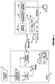
- Figure 1 depicts a generalized network with which three-dimensional compression according to the present invention may advantageously be used, to decrease storage space and to decrease time to transmit compress three-dimensional graphics objects.
- three-dimensional graphics compression according to the present invention may be used in other environments as well, e.g., to reduce requirements to store three-dimensional graphics on CD-ROMs, to compress data in real-time, for example, in an interactive television environment.
- a source of three-dimensional graphics data 10 may be coupled to a server or encoder system 20 whose processed and compressed output is coupled over one or more networks 30 to one or more target clients or decoder systems 40.
- the network may be homogeneous, heterogeneous, or point-to-point.
- Server 20 includes a central processing unit 50 that includes a central processor unit per se (“CPU”) 60 with associated main memory 70, a mesh buffer 80, a memory portion 90 that preferably contains an algorithm used to implement compression according to the present invention, and a region of read-only-memory (“ROM”) 100. Compression according to the present invention may be carried out in part of wholly in hardware as opposed to software.
- CPU central processor unit per se
- main memory 70 main memory
- mesh buffer 80 a memory portion 90 that preferably contains an algorithm used to implement compression according to the present invention
- ROM read-only-memory
- Server 20 also includes a three-dimensional graphics compression unit 60, whose compressed output data is arranged by a disk layout unit 70 for storage onto storage disk unit 80, which may include one or more CD-ROMs.
- the server communicates over the network(s) 30 via network interface unit 110.
- server 20 may include a mechanism for arbitrating between a plurality of client-decoder requests for compressed data.
- the compressed three-dimensional graphics data on video disk or CD-ROM 80 need not be transmitted over a network. Disk or CD-ROM 80 may, for example, be mailed to a user wishing to access the compressed three-dimensional graphics information stored thereon. However, if transmitted, e.g., over a network, transmission time will be advantageously reduced because the compression substantially reduces the bit-size of the file to be transmitted. Lossy compression of three-dimensional geometric data according to the present invention can produce ratios of six:one to ten:one, with little loss in displayed object quality. Further, such compression can be included at relatively low cost into real-time three-dimensional rendering hardware, or can instead be implemented using purely software techniques.
- decoder system(s) 40 include a central procession system 150 that includes a CPU 160, memory 170, a portion of which 180 may include decompression software, and ROM 190.
- a central procession system 150 that includes a CPU 160, memory 170, a portion of which 180 may include decompression software, and ROM 190.
- Three-dimensional graphics that have been compressed with an embodiment of the present invention may advantageously be decompressed using software, hardware, or a combination of each.
- Decoder 40 further includes a network interface unit 120, a unit 130 that decompresses three-dimensional graphics data, and whose output is coupled to a three-dimensional graphics rendering unit 140.
- the thus-decompressed three-dimensional graphics image(s) may then be coupled to a viewer 200, or to another system requiring the decompressed graphics.
- unit 40 may be a standalone unit, into which three-dimensional graphics data, precompressed according to an embodiment of the present invention, may be coupled for decompression.
- Unit 40 may, for example, comprise a computer or workstation.
- Applicant's patent application / filed on the same date as this application, entitled METHOD AND APPARATUS FOR DECOMPRESSION OF COMPRESSED GEOMETRIC THREE-DIMENSIONAL GRAPHICS DATA discloses a preferred method and system for decompressing data that has been compressed according to an embodiment of the present invention.
- Decompression can be implemented by means of a software implemented decompression algorithm, although the decompression could also be implemented in part or wholly in hardware.
- the first stage of geometry compression converts triangle data into an efficient linear strip form, namely a generalized triangle mesh.
- a triangle mesh data structure is a near-optimal representation of triangle data.
- three-dimensional graphics object may be represented as three-dimensional triangular data, whose format after conversion causes each linear strip vertex, on average, to specify from about 1/3 triangles to about 2 triangles.
- a generalized triangle strip structure permits compact representation of geometry while maintaining a linear data structure. Stated differently, the compressed geometry can be extracted by a single monotonic scan over the vertex array data structure. This feature is advantageous for pipelined hardware implementations.
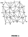
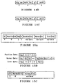
- Figure 2 depicts a generalized triangle mesh data structure, and generalized mesh buffer representation of surface geometry.
- a mesh data structure may be used in three-dimensional geometry compression, although by confining itself to linear strips, a generalized triangle strip format wastes a potential factor of two in space.
- a generalized triangle strip may be defined as follows, where the R denotes restart, O denotes replace oldest, M denotes replace middle, and a trailing letter p denotes push into mesh buffer.
- the number following a capital letter is a vertex number, and a negative number is the mesh buffer reference, in which -1 denotes the most recent pushed vertex.
- a generalized triangle mesh may be defined as follows:
- a vertex reference advantageously can be considerably more compact (e.g., be represented by fewer bits) than a full vertex specification.
- Geometry compression explicitly pushes old vertices (e.g., vertices with a trailing letter "p" above) into a queue associated with mesh buffer memory 80 (see Figure 1). These old vertices will later be explicitly referenced when the old vertex is desired again.
- buffer memory 80 has finite length, and in the preferred embodiment a maximum fixed queue length of 16 is used, which requires a 4-bit index.
- messages buffer shall refer to this queue, and the expression “generalized triangle mesh” will refer to a combination of generalized triangle strips and mesh buffer references.
- mesh buffer 80 requires all tessellators/re-strippers for compressed geometry to break-up any runs longer than sixteen unique references.
- geometry compression typically will not be programmed directly at the user level but rather by sophisticated tessellators/reformatters, this restriction is not onerous. Sixteen old vertices can in fact permit avoiding re-specification of up to about 94% of the redundant geometry.
- Figure 2 also is an example of a general mesh buffer representation of surface geometry.
- Geometry compression language supports the four vertex replacement codes of generalized triangle strips, namely: replace oldest, replace middle, restart clockwise, and restart counterclockwise. Further, the language adds an additional bit in each vertex header to indicate whether or not this vertex should be pushed into the mesh buffer.
- the mesh buffer reference command has a 4-bit field to indicate which old vertex should be re-referenced, along with the 2-bit vertex replacement code.
- Mesh buffer reference commands do not contain a mesh buffer push bit; old vertices can only be recycled once.
- entries into mesh buffer 80 contain storage for all associated per-vertex information, specifically including normal and color and/or texture map coordinate.
- each vertex normal and/or color information preferably is directly bundled with the position information.
- bundling is controlled by two state bits: bundle normals with vertices (BNV), and bundle colors with vertices (BCV).
- BNV bundle normals with vertices
- BCV bundle colors with vertices
- Figure 4E depicts a command structure including bits, among others. When a vertex is pushed into the mesh buffer, these bits control if its bundled normal and/or color are pushed as well.
- compression according to the present invention is not limited to triangles, and that vectors and dots may also be compressed.
- Lines for example, are a subset of triangles, in which replacement bits are MOVE and DRAW.
- An output vertex is then a vertex that represents one end point of a line whose other vertex is the most recently, previously omitted vertex.
- the replacement bits are DRAW, and an output vertex is the vertex.
- a replicate normals over triangle (RNT) bit indicates that the normal in the final vertex that completes a triangle should be replicated over the entire triangle.
- a replicate colors over triangle (RCT) bit is defined analogously, as shown in the command structure of Figure 4E.
- the difference ( ⁇ ) between adjacent vertices in the generalized mesh buffer stream is likely to be less than 16 bits in significance.
- a histogram representing bit length of neighboring position delta's in a batch of geometry, and based upon this histogram assign a variable length code to compactly represent the vertices.
- Huffman coding is used to encode for the positional delta's in the geometry compression.
- RGB ⁇ color data are first quantized to 12-bit unsigned fraction components that are absolute linear reflectivity values (in which 1.0 represents 100% reflectivity).
- An additional parameter allows color data effectively to be quantized to any amount less than 12 bits.
- colors may all be within a 5-5-5 RGB color space, as shown in Figure 4C.
- the optional ⁇ field is controlled by a color ⁇ present ("CAP") state bit shown in Figure 4E.
- CAP color ⁇ present
- the JPEG image compression standard relies upon assumptions about viewing of the decompressed data that cannot be made for geometry compression. For example, in image compression, it is known a priori that the pixels appear in a perfectly rectangular array, and that when viewed, each pixel subtends a narrow range of visual angles. By contrast, in geometry compression, the relationship between the viewer and the rasterized geometry is unpredictable.
- pseudo-color look-up tables It is known in the art to use pseudo-color look-up tables, but such tables would required a fixed maximum size, and would represent a relatively expensive resource for real-time processing. While pseudo-color indices could yield slightly higher compression ratios for certain scenes, the RGB model is more generalized and considerably less expensive to implement.
- RBG values are represented as linear reflectance values.
- all effects of lighting could be known a priori, one or two representation bits could be dropped if the RGB components had been represented in a nonlinear, or perceptually linear space (sometime referred to as gamma corrected space).
- gamma corrected space a nonlinear, or perceptually linear space
- N x 2 + N y 2 + N z 2 1
- at least one of N x , N y , or N z must be in the 0.5 to 1.0 range.
- N' y N x ⁇ T 1,o + N y ⁇ T 1,1 + N z ⁇ T 1,2
- N' z N x ⁇ T 2,o + N y ⁇ T 2,1 + N z ⁇ T 2,2
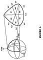
- the unit sphere is symmetrical by sign bits in the eight quadrants by sign bits.
- the six possible sextants are encoded with another three bits, which leaves only 1/48 of the sphere remains to be represented.
- the look-up table need store only about 2,000 entries, a size small enough to be an on-chip ROM look-up table, stored perhaps within ROM 59 (see Figure 1). Indexing into the look-up table requires 11 address bits, which when added to the previously described two 3-bit fields results in a 17-bit field to describe all three normal components.
- a scalable density distribution is desired, e.g., a distribution in which setting in the look-up table more low order address bits to "0" still results in fairly even normal density on the unit sphere. Otherwise a different look-up table for every encoding density would be required.
- a ⁇ -encodable distribution is desired in that adjacent vertices in geometry statistically have normals that are nearby on the surface of the unit sphere. Nearby locations on the two-dimensional space of the unit-sphere surface are most succinctly encoded by a two-dimensional offset. It is desirable to have a distribution in which such a metric exists.
- computational costs associated with the normal encoding process are not critically important, distributions having lower encoding costs are still preferred.
- the present embodiment utilizes a distribution having a regular grid in the angular space within one sextant of the unit sphere.
- all normals within a sextant are advantageously represented with two 6-bit orthogonal angular addresses.
- This configuration then revises the previous bit-total to 18-bits.
- these 6-bit indices can be reduced to fewer bits, and thus absolute normals can be represented using anywhere from 18 to as few as 6 bits.
- this space preferably is ⁇ -encoded to further reducing the number of bits required for high quality representation of normals.
- Points on the sphere are folded first by octant, and then by sort order of xyz into one of six sextants. All table encoding takes place in the positive octant in the region bounded by the half spaces: x ⁇ z z ⁇ y y ⁇ 0
- the described triangular-shaped patch runs from 0 to ⁇ /4 radians in ⁇ , and from 0 to a maximum 0.615479709 radians in ⁇ .
- Quantized angles are represented by two n-bit integers ⁇ & n and ⁇ & n , where n is in the range of 0 to 6.
- n is in the range of 0 to 6.
- Equations (2) show how values of ⁇ & n and ⁇ & n can be converted to spherical coordinates ⁇ and ⁇ , which in turn can be converted to rectilinear normal coordinate components via equation (1).
- This representation of normals is amenable to ⁇ -encoding, at least within a sextant, although with some additional work, this can be extended to sextants that share a common edge.
- the ⁇ code between two normals is simply the difference in ⁇ & n and ⁇ & n , namely ⁇ & n and ⁇ & n .
- the Huffman compression algorithm takes in a set of symbols to be represented, along with frequency of occurrence statistics (e.g., histograms) of those symbols. From this, variable length, uniquely identifiable bit patterns are generated that allow these symbols to be represented with a near-minimum total number of bits, assuming that symbols do occur at the frequencies specified.
- frequency of occurrence statistics e.g., histograms
- variable-length data-field that follows.
- This data field is typically a specific-length delta value.
- the final binary stream consists of (self-describing length) variable length tag symbols, each immediately followed by a data field whose length is associated with that unique tag symbol.
- the binary format for geometry compression uses this technique to represent position, normal, and color data fields.
- these ⁇ tag, data ⁇ fields are immediately preceded by a more conventional computer instruction set op-code field.
- These fields, along with potential additional operand bits, will be referred to as geometry instructions (see Figures 4A-4K).
- each to be compressed value is assigned its own associated label, e.g. an xyz ⁇ position would be represented by three tag-value pairs. But since the ⁇ xyz values are not uncorrelated, a denser, simpler representation can be attained. In general, the xyz ⁇ 's statistically point equally in all directions in space. Thus, if n is the number of bits needed to represent the largest of the ⁇ 's, then statistically the other two ⁇ values require an average of n-1.4 bits for their representation.
- the preferred embodiment therefore uses a single field-length tag to indicate the bit length of ⁇ x, ⁇ y, and ⁇ z. although other design choices could have been made.
- Absolute and ⁇ normals are also parameterized by a single value (n) that can be specified by a single tag.
- n the length of the Huffman tag field was limited to six bits, a relatively small value.
- a 64-entry tag look-up table allows decoding of tags in one clock cycle. One table exists for positions, another table exists for normals, and yet another table exists for colors (and optionally, also for texture coordinates). Each table contains the length of the tag field, the length of the data field(s), a data normalization coefficient, and an absolute/relative bit.
- Figure 4A depicts a vertex command that specifies a Huffman compressed ⁇ -encoded position, as well as possibly a normal and/or color, depending on bundling bits (BNV and BCV). Two additional bits specify a vertex replacement code (REP), and another bit controls mesh buffer pushing of this vertex (MBP).
- REP vertex replacement code
- MBP mesh buffer pushing of this vertex
- a normal command specifies a new current normal and the color command shown in Figure 4C depicts a new current color.
- the normal command and color command each use Huffman encoding of ⁇ values.
- the mesh buffer reference command structure is shown in Figure 4D.
- the mesh buffer reference command allows any of the sixteen most recently pushed vertices (and associated normals and/or colors) to be referenced as the next vertex.
- a 2-bit vertex replacement (“REP") code is also specified.
- Figure 4E depicts the set state instruction that updates the five state bits: RNT, RCT, BNV, BCV, and CAP.
- Figure 4F depicts a set table command, which is used to set entries to the entry value specified in one of the three Huffman decoding tables (Position, Normal, or Color).
- Figure 4G depicts a passthrough command that allows additional graphics state not controlled directly by geometry compression to be updated in-line.
- FIG. 4H depicts a variable length no-op ("VNOP") command that allows fields within the bit stream to be aligned to 32-bit word boundaries. This permits aligned fields to be efficiently patched at run-time by the general CPU 52.
- VNOP variable length no-op
- Figures 4I, 4J and 4K respectively depict tag and ⁇ -position data structure, tag and ⁇ -normal data structure, and tag and ⁇ -color data structure.
- the ratio of the time required for compression relative to decompression is an important measure for many forms of compression. In practice, it is acceptable for off-line image compression to take up to perhaps sixty-times more time than decompression, but for real-time video conferencing, the ratio should be one.
- geometry compression does not have this real-time requirement. Even if geometry is constructed on the fly, most geometry creating techniques, e.g., CSG, require orders of magnitude more time than needed for displaying geometry. Also, unlike continuous images found in movies, in most applications of geometry compression a compressed three-dimensional object will be displayed for many sequential frames before being discarded. Should the three-dimensional object require animating, animation is typically done with modeling matrices. Indeed for a CD-based game, it is quite likely that an object will be decompressed billions of times by customer-users, but will have been compressed only once by the authoring company.
- geometry compression algorithms can have a compression-time vs. compression-ratio trade-off. For a given quality target level, as allowable time for compression increases, the compression ratio achieved by a geometry compression system increases. There exists a corresponding "knob" for quality of the resulting compressed three-dimensional object, and lower the quality knob, the better the compression ratio achieved.
- Aesthetic and subjective judgment may be applied to geometry compression. Some three-dimensional objects will begin to appear bad when target quantization of normals and/or positions is slightly reduced, whereas other objects may be visually unchanged even with a large amount of quantization. Compression can sometimes cause visible artifacts, but in other cases may only make the object look different, not necessarily lower in quality. In one experiment by applicant, an image of an elephant actually begin to appear more realistic, with more wrinkle-like skin, as the image normals were quantized more. Once a model has been created and compressed, it can be put into a library, to be used as three-dimensional clip-art at the system level.
- geometry compression instruction set has been somewhat tailored to permit low-cost, high-speed hardware implementations. (It is understood that a geometry compression format designed purely for software decompression would be somewhat different.).
- the preferred geometry compression instruction set is especially amenable to hardware implementation because of the one-pass sequential processing, limited local storage requirements, tag look-up (as opposed to a conventional Hamming bit-sequential processing), and use of shifts, adds, and look-ups to accomplish most arithmetic steps.
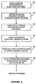
- Figure 5 is a flowchart outlining method steps in a geometry compression algorithm routine, according to the present embodiment. Such routine may be stored in memory 80 and executed under control of CPU 60 (see Figure 1).
- an object is represented by an explicit group of triangles to be compressed, along with quantization thresholds for positions, normals, and colors.
- a topological analysis of connectivity is made, and hard edges are marked in normals and/or color, if such information is not already present.
- vertex traversal order and mesh buffer references are created, and at step 230 histograms of ⁇ -positions, ⁇ -normals, and ⁇ -colors is created.
- step 240 separate variable length Huffman tag codes are assigned for the ⁇ -positions, ⁇ -normals, and ⁇ -colors, based upon histographs.
- a binary output stream is generated by first outputting Huffman table initialization, after which the vertices are traversed in order. Appropriate tags and ⁇ 's are output for all values.
- Applicant has implemented a Wavefront OBJ format compressor that supports compression of positions and normals, and creates full generalized triangle strips, but does not yet implement a full meshifying algorithm. Future embodiments will explore variable precision geometry, including fine structured updates of the compression tables. The present compressor expends time calculating geometric details already known to the tessellator, and ultimately it is hoped to generate compressed geometry directly. However, even its present unoptimized state, applicant's software can compress about 3,000 triangles/second in many cases.
- An applicable geometry decompression algorithm may be outlined as follows:
- Applicant has implemented a software decompressor that successfully decompresses compressed geometry at a rate of about 10,000 triangles/second.
- Hardware designs are in progress, a simplified block diagram can be seen in figure 6.
- the rate of hardware decompression may in the range of tens of millions of triangles/second.
- Figures 7A-7 and in Table 1, below Comparative uncompressed and compressed image results are shown in Figures 7A-7 and in Table 1, below.
- Figures 7A-7G depicts the same base object, a triceratops, but with different quantization thresholds on positions and normals.
- Figure 7A is the original full floating-point representation, using 96-bit positions and 96-bit normals, denoted by the nomenclature P96/N96.
- Figure 7B and 7C depicts the effects of purely positional quantization P36/N96 and P24/N96, respectively, while Figures 7D and 7E depict only normal quantization, P96/N18 and P96/N12.
- Figures 5f and 5g show combined quantization, P48/N18 and P30/N36.
- Figures 7H-7L depict only quantized results for different objects, including a galleon (P30/N12), a Dodge Viper (P36/N14), two views of a '57 Chevy (P33/N13), and an insect (P39/N15).
- Table 1 summarizes compression and other statistics for these objects. Column 1 notes the object in question, column 2 represents the number of ⁇ 's, and column three the ⁇ -strip length. The fourth column represents system overhead per vertex (overhead being everything beyond position tag/data, and normal tag/data).
- the "xyz quant” column denotes quantization thresholds, and the sixth column depicts the number of bits/xyz.
- "Bits/tri” ninth column depicts bits per triangle.
- Table 1 The results in Table 1 are measured actual compression data except for estimated mesh buffer results, which are shown in parenthesis. No actual mesh buffer results were present in that applicant's prototype software compressor did not yet implement a full meshifying algorithm. The estimate (in parenthesis) assumes a 46% hit ratio in the mesh buffer.
- Table 1 also shows byte count for the mode of OpenGL. As shown, average strip length decreased in the range of 2-3. Few if any commercial products take advantage of generalized triangle strips, and thus Table 1 considerably understates potential memory space savings.
- geometry compression can represent three-dimensional triangle data with a factor of six to ten times fewer bits than required with conventional techniques.
- Applicant's geometry compression algorithm may be implemented in real-time hardware, or in software. For a fixed number of triangles, compression can minimize the total bit-size of the representation, subject to quality and implementation trade-offs.
- the resultant geometry-compressed image suffers only slight losses in object quality, and may be decompressed using software or hardware implementations.
- three-dimensional rendering hardware contains a geometry decompression unit
- application geometry may be stored in memory in compressed format. Further, data transmission may use the compressed format, thus improving effective bandwidth for a graphics accelerator system, including shared virtual reality display environments.
- the resultant compression can substantially increase the amount of geometry cacheable in main memory.
- FIG 8 is a detailed block diagram of the decompressor unit 130, shown in Figure 1.
- unit 130 includes a decompression input first-in-first-out register (“FIFO") 200 whose inputs include control signals and a preferably 32-bit or 64-bit data stream, which signals and data stream preferably come from an accelerator port data FIFO ("APDF") in interface unit 120 (see Figure 1).
- APDF accelerator port data FIFO
- the APDF portion of interface 120 includes a controller that signals the size of the incoming data stream to unit 130.
- FIFO 200 provides output to an input block state machine 220 and to an input block 210, state machine 220 and input block unit 210 communicating with each other.
- Output from block 210 is coupled to a barrel shifter unit 240 and to a Huffman table set 230, the output from the Huffman look-up being coupled to state machine 220.
- Opcode within state machine 220 processes the values provided by the Huffman tables 230 and outputs data to the barrel shifter unit 240.
- State machine 220 also provides an output to data path controller 260, which outputs a preferably 12-bit wide signal to a tag decoder unit 294 and also outputs data to the barrel shifter unit 240 and to a normal processor 270, and a position/color processor 280.
- Barrel shifter unit 240 outputs to the normal processor 270 and to a position/color processor 280.
- the outputs from processors 270 and 280 are multiplexed by output multiplexer unit 290 into a preferably 48-bit wide signal that is provided to a format converter 292.
- Decompression unit 130 generates a preferably 12-bit tag that is sent to tag decoder 294 in parallel with either 32-bits or 48-bits (for normals), that are sent to the format converter 292. These data streams provide instructions that generate output to format converter 292. A preferably 32-bit read-back path is used to read-back the state of the unit.
- Table 2 shows interface signals used to implement a preferred embodiment of a decompression unit 130: Signal Name Signals I/O Description id_data 64 I Data inputs from APDF id_tag 12 I Data on inputs is valid from APDF fd_stall 1 I Stall signal from format converter di_busy 1 O Busy signal to status register di_faf 1 O Fifo-almost-full signal-to-input FIFO df_data 48 O Data output to formal converter df_tag 12 O Tag output to tag decoder du_context 32 O Context output to UPA section
- Table 3 shows output data formats provided by unit 130.
- vertex, mesh buffer reference, and passthrough instructions generate transactions from decompression unit 130.
- Vertex and mesh buffer reference instructions send data to the format converter, and each generates a header indicating vertex replacement policy for the current vertex, followed by component data.
- Each of these instructions always generates position data and, depending upon the value of the state register, may contain color or normal data. All three of the normal components preferably are sent in parallel, whereas each position and color component is separately sent.
- a passthrough instruction sends preferably 32-bits of data to the collection buffer. COMPONENTS FORMAT Header 32. Position s.15 Color s.15 Normal s1.14(x3) Passthrough 32.
- Figure 9 is a detailed block diagram of the input block 210 depicted in Figure 8.
- a preferably 64-bit input register 300 receives data from the APDF portion of interface 130, with 32-bits or 64-bits at a time being loaded into register 300.
- Register 300 outputs preferably 32-bits at a time via multiplexer 310 to a first barrel shifter 320 whose output passes through a register 330 into a merge unit 340.
- the 64-bit output from merge unit 340 is input to data register 350, part of whose output is returned as input to a second barrel shifter 360.
- the output from second barrel shifter 360 is passed through a register 370 and is also input to merge unit 340.
- First barrel shifter 320 aligns data to the tail of the bit-aligned data stream being recycled from data register 350 through second barrel shifter 360.
- the second barrel shifter 360 shifts-off the used bits from data register 350.
- FIG 10 is a detailed block diagram of barrel shifter unit 240, shown in Figure 8.
- barrel shifter unit 240 expands the variable-length position, color, and normal index components to their fixed-point precisions.
- Data into unit 240 from unit 210 and/or 220 is input to a register 400 whose output is shown as defining opcode and/or data units 410, 420, 430, 440, 450, and 460, which are input to a multiplexer unit 470.
- Unit 240 further includes a barrel shift left register 480 coupled to receive tag_len data and to output to register 490, whose output in turn is input to a barrel shift right register 500 that is coupled to receive data_len data.
- Register 500 outputs to a mask unit 510 that is coupled to receive shift data and whose output is coupled to register 520, which outputs v_data.
- the output of data block 460 is coupled to a register 530 whose output is coupled to a second register 540, which outputs pt_data.
- Huffman tables 230 provide values of tag_len, data_len, and shift into units 480, 500 and 510, respectively.
- Barrel shift left unit 480 shifts the input data left by 0 to 6 bits (tag_len), thus shifting off the Huffman tag.
- barrel shift right register 500 shifts the data to the right by 0 to 16 bits (16 - data_len), and sign extends the data, thus bringing the data to its full size.
- Mask unit 510 masks off the lower 'shift' bits to clamp the data to the correct quantization level.
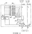
- FIG 11 depicts in greater block diagram detail the position/color processor unit 280, shown in Figure 8.
- Processor unit 280 generates final position or color component values.
- processor unit 280 receives a preferably 16-bit value (v_data) from the barrel shifter unit 240, specifically mask unit 510 therein.
- the incoming data are added by combiner unit 600 to the appropriate current stored data.
- the new value passes through multiplexer 610, and is stored back into the register 620, and is sent along to the output multiplexer 290, shown in Figure 8.
- the abs_rel bit is set to absolute, the incoming data bypasses adder 600, is latched into the register 620, and is also sent out to the output multiplexer 290.
- the position/color processor unit 280 further includes a position/color mesh buffer 630 that is coupled to receive the input to register 620.
- the output from mesh buffer 630 is coupled to multiplexer gates, collectively 640, whose outputs reflect current values of x, y, z, r, g, b and ⁇ .
- a register set, collectively shown as 650, provides these current values to the input of a multiplexer 660, whose output is coupled to the adder 600.
- Processor unit 280 further includes a register 670 that receives and outputs pt_data from barrel shifter unit 240.
- normal processor unit 270 also outputs data to the output multiplexer 290.
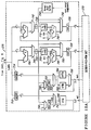
- Figure 12A depicts in detail the sub-units comprising normal processor unit 270.
- the normal processor unit 270 receives an 18-bit normal index as three separate components: sextant/octant, u and v , or encoded ⁇ u and ⁇ v components from mask unit 510 in barrel shifter unit 240. If the value is a ⁇ -value (relative), the ⁇ u and ⁇ v are added to the current u and v values by respective adders 710. The intermediate values are stored and are also passed on to a fold unit 800 associated with decoder-fold-rom unit 272 (see Figure 12B).
- the normal processor unit 270 further includes registers 712, 714, 716, 718, 720, 722, 724, 726 which hold respective octant, sextant, u and v values, curr_oct, curr_sext, curr_u and curr_v values. Also present in unit 270 are multiplexers 740, 742, 744, 746, 748, 750, 752, 754, 756, 758 and 760, 1's complementing units 770, 772, latch-flipflop units 780, 782, 784 for holding respective v, u, and uv information, further adders 790, 792, and a normal mesh buffer 794 coupled to receive curr_normal input components.
- the u and v values are passed directly to fold unit 800.
- the octant and sextant portions of the index are sent to decoder 810, within unit 272.
- Decoder 810 controls multiplexer 820 (which select constants), as well as multiplexers 840, 842, 844, 860, 862, 864, which reorder components, and invert signs (using 2's complement units 850, 852, 854).
- Fold unit 800 uses the u and v components of the normal index, from unit 270, to calculate the address into the normal look-up table ROM 830.
- the octant and sextant fields, from unit 270, drive a decoder 810 that determines sign and ordering of components output from the ROM look-up table 830. Decoder 810 also handles special case normals not included in the normal ROM look-up table 830.
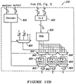
- FIG 13 depicts interfaces to a mesh buffer, as shown in Figure 11 and/or Figure 12A.
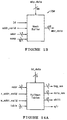
- FIG 14A depicts interfaces to Huffman tables, e.g., tables 230 in Figure 8.
- Huffman tables are used to decode the Huffman tags preceding the compressed data.
- Three Huffman tables are used: one for position, for color, and for normal data, with each table preferably holding 64 entries.
- Figure 14B depicts a preferred format for entry of position and color data in the Huffman tables
- Figure 14C depicts the preferred format for normal table entries.
- the instruction format for loading the Huffman tables in the compressed data stream is described later herein.
- Table 4 shows tags generated for the different data components.
- the components that show two tags may set the launch bit, and the second tag shows the value with the launch bit set.
- COMPONENTS TAG Header 0x020 X 0x011 Y 0x012 Z 0x013/0x413 Nx/Ny/Nz 0x018/0x418 R 0x014 G 0x015 B 0x016/0x416 A 0x017/0x417 U 0x0c0/0x4c0 V 0x01c/0x41c
- Input block state machine 220 includes a preferably six-bit state register that holds information about the processing state of the decompression unit.
- the following state bits are defined:
- Position/Color processor unit 280 (see Figures 8 and 11) preferably includes three 16-bit registers, curr_x, curr_y, and curr_z, which contain the current position components, X, Y, and Z, and are only updated by vertex instructions.
- Normal processor unit 270 preferably includes three six-bit registers, curr_oct, curr_sext, curr_u, curr_v) that contain the current normal.
- the first register holds the 3-bit sextant and octant fields, and the remaining two registers contain the u and v coordinates for the normal. These values are written using the set normal instruction, or they are updated by the vertex instruction if the bnv bit is set in the state register.
- Position/color processor 280 further preferably includes four 16-bit registers, curr_r, curr_g, curr_b, curr_a, which contain the current color components, red, green, blue and alpha ( ⁇ ). These components are set using the se5t color instruction, or they are updated by the vertex instruction if the bcv bit is set in the state register. Preferably, alpha is valid only if the cap bit is set in the state register. The test bit is set when processing texture components, in which case only red and green are valid.
- Figure 15A depicts the vertex instruction format, an instruction that uses variable-length Huffman encoding to represent a vertex. Position information is always present in this instruction.
- the position data consists of a variable-length Huffman tag (0 to 6 bits) followed by three data fields of equal length for the X, Y, and Z components, which are either ⁇ -values or absolute values.
- the data_len field for the entry in the position Huffman table gives the length of each of the X, Y, and Z fields
- the tag_len entry gives the length of the tag
- the abs_rel entry tells whether the data is absolute data or is relative to the previous vertex.
- the shift entry from the Huffman table gives the quantization level (number of trailing zeroes) for the data.
- a normal is included.
- the encoded normal has a Huffman tag followed by either two variable-length data fields for ⁇ u and ⁇ v , or a fixed-length field for the sextant and octant (6 bits) followed by two variable-length fields for u and v .
- the former encoding is for delta encodings of normals, while the latter encoding is for absolute encodings.
- the data_len, tag_len, abs_rel, and shift fields from the normal Huffman table are used similarly as entries from the position table.
- Figure 15B depicts vertex component data formats. If the bcv bit in the state register is set, color is included with the vertex. The color is encoded similar the position, using three or four fields, but how the fields are used is determined by the tag table. If tagged absolute, then x, y, z, r, g, b data is used. Absolute normals are used with sectant and octant fields. However, if the tag table indicates relative, delta normals are used, and it suffices to send latitude and longitude data (e.g., ⁇ and ⁇ , also referred to herein as u and v .
- latitude and longitude data e.g., ⁇ and ⁇ , also referred to herein as u and v .
- a Huffman tag is followed by three equal length fields for R, G, and B.
- the cap bit in the state register indicates whether an additional field for ⁇ is included.
- the data_len, tag_len, abs_rel, and shift fields from the color Huffman table are used similarly as for entries from the position and normal tables.
- the states of the vertex instruction set are as follows:
- Figure 15C depicts the format for the set normal instruction.
- the set normal instruction sets the value of the current normal registers.
- the normal data is encoded similarly as is normal data in the vertex instruction, described herein.
- the states of the set normal instruction are as follows:
- Figure 15D depicts the set color instruction, an instruction that sets the value of the current color registers. Encoding of the color data is similar to encoding of the color data in the vertex instruction.
- the states of the set color instruction are as follows:
- FIG. 15E is a preferred format for the mesh buffer reference instruction.
- This instruction causes data from an entry in the mesh buffer to be sent out to the format converter as the next vertex.
- the index indicates the entry from the mesh buffer to send.
- the newest entry in the mesh buffer has index 0, and the oldest has index 15.
- REP the above-described replacement policy for the vertex instruction, is the same as used for the mesh buffer reference instruction.
- the states for the mesh buffer reference instruction are as follows:
- Figure 15F depicts the set state instruction, which sets the bits the decompression unit state register.
- the states for the set state instruction are as follows:
- FIG. 15G depicts the set table instruction, which sets Huffman table entries.
- the table selection is as follows:
- the tag length is derived from the address.
- the nine bits in the entry field correspond to the absolute/relative bit, data length, and shift amount fields of the Huffman table entries. (The preferred format of the Huffman table entries has been described earlier herein.)
- the states of the set table instruction are as follows:
- Table 5 shows the preferred Huffman Table Fill Codes. Address Entries Filled Tag Length Fill Range 0tttttt 1 6 tttttt 10ttttt 2 5 ttttt0 -ttttt1 110tttt 4 4 tttt00 -tttt11 1110ttt 8 3 ttt000 -ttt111 11110tt 16 2 tt0000 -tt1111 111110t 32 1 t00000 -t11111 1111110 64 0 Entire table
- Figure 15H depicts the passthrough instruction, which allows passthrough data to be encoded in the compressed-data stream.
- the length of the instruction preferably is 64-bits. Aligning successive passthrough instructions to a 64-bit boundary allows for patching of passthrough data in the encoded stream.
- the states for the passthrough instruction are as follows:
- Figure 15I depicts the variable-length NOP ("VNOP) instruction, which encodes a variable number of 0 bits in the data stream.
- VNOP variable-length NOP
- the five-bit count shown in Figure 15I designates the number of 0 bits that follow.
- This instruction is implicitly used for the start of the data stream. This instruction may also be used to pad the data stream to 32-bit or 64-bit boundaries, or encoding regions, for later patching.
- the states for this instruction are:
- Figure 15J shows the skip 8 instruction, whose states are:
- parallel decompression of a data stream may be implemented by providing an additional command advising the arrival of a given number of data words that may be processed in parallel.
- morphing capability may be implemented to eliminate any abrupt perception gap in viewing a decompressed three-dimensional object.
- vertices Assume, for example, that the three-dimensional object is a tiger. At a far distance, no teeth are present in the tiger's mouth, yet at near distance teeth are present. The result is a seamless transition such that as distance to the tiger shrinks, the teeth grow, with no sudden change seen between a toothless tiger and a toothed tiger.
Abstract

Description
- The present invention relates generally to compressing three-dimensional graphics data, and more particularly to methods and apparatuses that provide lossy high compression ratios for three-dimensional geometry compression.
- Modern three-dimensional computer graphics use geometry extensively to describe three-dimensional objects, using a variety of graphical representation techniques. Computer graphics find wide use in applications ranging from computer assisted design ("CAD") programs to virtual reality video games. Complex smooth surfaces in of objects can be succinctly represented by high level abstractions such as trimmed non-uniform rational splines ("NURBs"), and often detailed surface geometry can be rendered using texture maps. But adding more realism requires raw geometry, usually in the form of triangles. Position, color, and normal components of these triangles are typically represented as floating point numbers, and describing an isolated triangle can require upwards of 100 bytes of storage space.
- Understandably, substantial space is necessary for three-dimensional computer graphics objects to be stored, e.g., on a computer hard disk or compact disk read-only memory ("CD-ROM"). Similarly, considerable time in necessary for such objects to be transmitted, e.g., over a network, or from disk to main memory.
- Geometry compression is a general space-time trade-off, and offers advantages at every level of a memory/interconnect hierarchy. A similar systems problem exists for storage and transmission of two-dimensional pixel images. A variety of lossy and lossless compression and decompression techniques have been developed for two-dimensional pixel images, with resultant decrease in storage space and transmission time. Unfortunately, the prior art does not include compression/decompression techniques appropriate for three-dimensional geometry, beyond polygon reduction techniques. However, the Ph.D. thesis entitled Compressing the X Graphics Protocol by John Danskin, Princeton University, 1994 describes compression for two-dimensional geometry.
- Suitable compression can greatly increase the amount of geometry that can be cached, or stored, in the fast main memory of a computer system. In distributed networked applications, compression can help make shared virtual reality ("VR") display environments feasible, by greatly reducing transmission time.
- Most major machine computer aided design ("MCAD") software packages, and many animation modeling packages use constructive solid geometry ("CSG") and free-form NURBS to construct and represent geometry. Using such techniques, regions of smooth surfaces are represented to a high level with resulting trimmed polynomial surfaces. For hardware rendering, these surfaces typically are pre-tessellated in triangles using software before transmission to rendering hardware. Such software pre-tessellation is done even on hardware that supports some form of hardware NURBS rendering.
- However, many advantages associated with NURBS geometric representation are for tasks other than real-time rendering. These non-rendering tasks include representation for machining, interchange, and physical analysis such as simulation of turbulence flow. Accurately representing trimming curves for NURBS is very data intensive, and as a compression technique, trimmed NURBS can not be much more compact than pre-tessellated triangles, at least at typical rendering tessellation densities. Finally, not all objects are compactly represented by NURBS. Although many mechanical objects such as automobile hoods and jet turbine blades have large, smooth areas where NURBS representations can be advantageous, many objects do not have such areas and do not lend themselves to such representation. Thus, while NURBS will have many applications in modelling objects, compressed triangles will be far more compact for many classes of application objects.
- Photo-realistic batch rendering has long made extensive use of texture map techniques to compactly represent fine geometric detail. Such techniques can include color texture maps, normal bump maps, and displacement maps. Texture mapping works quite well for large objects in the far background, e.g., clouds in the sky, buildings in the distance. At closer distances, textures work best for three-dimensional objects that are mostly flat, e.g., billboards, paintings, carpets, marble walls, and the like. More recently, rendering hardware has begun to support texture mapping, and real-time rendering engines can also apply these techniques.
- However, texture mapping results in a noticeable loss of quality for nearby objects that are not flat. One partial solution is the "signboard", in which a textured polygon always swivels to face the observer. But when viewed in stereo, especially head-tracked VR stereo, nearby textures are plainly perceived as flat. In these instances, even a lower detail but fully three-dimensional polygonal representation of a nearby object would be much more realistic.
- Polyhedral representation of geometry has long been supported in the field of three-dimensional raster computer graphics. In such representation, arbitrary geometry is expressed and specified typically by a list of vertices, edges, and faces. As noted by J. Foley, et al. in Computer Graphics: Principles and Practice, 2nd ed., Addison-Wesley, 1990, such representations as winged-edge data structures were designed as much to support editing of the geometry as display. Vestiges of these representations survive today as interchange formats, e.g., Wavefront OBJ. While theoretically compact, some compaction is sacrificed for readability by using ASCII data representation in interchange files. Unfortunately, few if any of these formats can be directly passed as drawing instructions to rendering hardware.
- Another historical vestige in such formats is the support of N-sided polygons, a general primitive form that early rendering hardware could accept. However, present day faster rendering hardware mandates that all polygon geometry be reduced to triangles before being submitted to hardware. Polygons with more than three sides cannot in general be guaranteed to be either planar or convex. If quadrilaterals are accepted as rendering primitives, it is to be accepted that they will be arbitrarily split into a pair of triangles before rendering.
- Modern graphics languages typically specify binary formats for the representation of collections of three-dimensional triangles, usually as arrays of vertex data structures. Thus, PHIGS PLUS, PEX, XGL, and proposed extensions to OpenGL are of this format form, and will define the storage space taken by executable geometry.
- It is known in the art to isolate or chain triangles in "zigzag" or "star" strips. For example, Iris-GL, XGL, and PEX 5.2 define a form of generalized triangle strip that can switch from a zigzag to star-like vertex chaining on a vertex-by-vertex basis, but at the expense of an extra header word per vertex in XGL and PEX. A restart code allows multiple disconnected strips of triangles to be specified within one array of vertices.
- In these languages, all vertex components (positions, colors, normals) may be specified by 32-bit single precision IEEE floating point numbers, or 64-bit double precision numbers. The XGL, IrisGL, and OpenGL formats also provide some 32-bit integer support. The IrisGL and OpenGL formats support vertex position component inputs as 16-bit integers, and normals and colors can be any of these as well as 8-bit components. In practice, positions, colors, and normals can be quantized to significantly fewer than 32 bits (single precision IEEE floating point) with little loss in visual quality. Such bit-shaving may be utilized in commercial three-dimensional graphics hardware, providing there is appropriate numerical analysis support.
- In summation, there is a need for graphics compression that can compress three-dimensional triangles, and whose format may be directly passed as drawing instructions to rendering hardware. Preferably such compression should be readily implementable using real-time hardware, and should permit decompression using software or hardware.
- Aspects of the invention are set out in the accompanying independent claims. Preferred and further features of the invention are set out in the dependent claims. Different combinations of the features of the dependent claims may be made, as appropriate, with the features of the independent claims.
- According to an embodiment of the present invention, geometry is first represented as a generalized triangle mesh, which structure allows each instance of a vertex in a linear stream preferably to specify an average of between 1/3 triangle and 2 triangles. Individual positions, colors, and normals are quantized, with a variable length compression being applied to individual positions, colors, and normals. Quantized values are delta-compression encoded between neighbors to provide vertex traversal orders, and mesh buffer references are created. Histograms of delta-positions, delta-normals and delta-colors are created, after which variable length Huffman tag codes, as well as delta-positions, delta-normals and delta-colors are created. The compressed output binary stream includes the output Huffman table initializations, ordered vertex traversals, output tags, and the delta-positions, delta-normals, and delta-colors.
- Decompression reverses this process. The decompressed stream of triangle data may then be passed to a traditional rendering pipeline, where it can be processed in full floating point accuracy, and thereafter displayed or otherwise used.
- Other features and advantages of the invention will appear from the following description in which the preferred embodiments have been set forth in detail, by way of example only, in conjunction with the accompanying drawings, in which
-
- FIGURE 1 depicts a generalized network system over which three-dimensional graphics compressed according to the present invention may be transmitted, and decompressed for user viewing;
- FIGURE 2 depicts a generalized triangular mesh data structure, and generalized mesh buffer representation of surface geometry, according to an embodiment of the present invention;
- FIGURE 3 depicts six-way sign-bit and eight-way octant symmetry in a unit sphere, used to provide forty-eight way reduction in table look-up size, according to the present embodiment;
- FIGURE 4A depicts a vertex command in a geometry compression instruction set, according to the present embodiment;
- FIGURE 4B depicts a normal command in a geometry compression instruction set, according to the present embodiment;
- FIGURE 4C depicts a color command in a geometry compression instruction set, according to the present embodiment;
- FIGURE 4D depicts a mesh buffer reference command in a geometry compression instruction set, according to the present embodiment;
- FIGURE 4E depicts a set state instruction in a geometry compression instruction set, according to the present embodiment;
- FIGURE 4F depicts a set table command instruction in a geometry compression instruction set, according to the present embodiment;
- FIGURE 4G depicts a pass through command instruction in a geometry compression instruction set, according to the present embodiment;
- FIGURE 4H depicts a variable length no-op command instruction in a geometry compression instruction set, according to the present embodiment;
- FIGURE 4I depicts tag and Δ-position data structure, according to the present embodiment;
- FIGURES 4J-1 and 4J-2 depict alternative tag and Δ-normal data structure, according to the present embodiment;
- FIGURE 4K depicts tag and Δ-color data structure, according to the present embodiment;
- FIGURE 5 is a flowchart of method steps in a geometry compression algorithm, according to the present embodiment;
- FIGURE 6 is a block diagram of decompressor hardware, suitable for use with the present embodiment;
- FIGURES 7A-7L depict objects compressed under different conditions with the present embodiment;
- FIGURE 8 is a detailed overall block diagram of a decompressor unit suitable for decompressing data compressed according to an embodiment of the present invention;
- FIGURE 9 is a detailed block diagram of the input block shown in Figure 8;
- FIGURE 10 is a detailed block diagram of the barrel shifter unit shown in Figure 8;
- FIGURE 11 is a detailed block diagram of the position/color processor unit shown in Figure 8;
- FIGURE 12A is a detailed block diagram of the normal processor unit shown in Figure 8;
- FIGURE 12B is a detailed block diagram showing the decoder, fold, and ROM look-up components associated with the normal processor unit of Figure 12A;
- FIGURE 13 is a block diagram showing interfaces to a mesh buffer, as shown in Figure 11 and/or Figure 12A;
- FIGURE 14A depicts interfaces to Huffman tables;
- FIGURE 14B depicts a preferred format for entry of the Huffman table data;
- FIGURE 15A depicts a vertex instruction;
- FIGURE 15B depicts vertex component data formats;
- FIGURE 15C depicts the format for the set normal instruction;
- FIGURE 15D depicts a set color instruction;
- FIGURE 15E depicts a mesh buffer reference instruction;
- FIGURE 15F depicts a set state instruction;
- FIGURE 15G depicts a set table instruction;
- FIGURE 15H depicts a passthrough instruction;
- FIGURE 15I depicts a variable-length NOP instruction; and
- FIGURE 15J depicts a skip 8 instruction.
-
- A graphics compressor according to an embodiment of the present invention may be used to reduce the space needed to store three-dimensional graphics object, e.g., on a CD-ROM or the like, as well as to reduce the time needed to transmit a compressed three-dimensional graphics object, for example over a network. Before describing three-dimensional graphics compression per se, the overall environment in which the present invention may be practiced will be described with respect to Figure 1.
- Figure 1 depicts a generalized network with which three-dimensional compression according to the present invention may advantageously be used, to decrease storage space and to decrease time to transmit compress three-dimensional graphics objects. Of course, three-dimensional graphics compression according to the present invention may be used in other environments as well, e.g., to reduce requirements to store three-dimensional graphics on CD-ROMs, to compress data in real-time, for example, in an interactive television environment.
- As shown in Figure 1, a source of three-dimensional graphics data 10 may be coupled to a server or encoder system 20 whose processed and compressed output is coupled over one or more networks 30 to one or more target clients or decoder systems 40. The network may be homogeneous, heterogeneous, or point-to-point.
- Server 20 includes a central processing unit 50 that includes a central processor unit per se ("CPU") 60 with associated main memory 70, a mesh buffer 80, a memory portion 90 that preferably contains an algorithm used to implement compression according to the present invention, and a region of read-only-memory ("ROM") 100. Compression according to the present invention may be carried out in part of wholly in hardware as opposed to software.
- Server 20 also includes a three-dimensional graphics compression unit 60, whose compressed output data is arranged by a disk layout unit 70 for storage onto storage disk unit 80, which may include one or more CD-ROMs. The server communicates over the network(s) 30 via network interface unit 110. Those skilled in the art will appreciate that server 20 may include a mechanism for arbitrating between a plurality of client-decoder requests for compressed data.
- It is to be understood that the compressed three-dimensional graphics data on video disk or CD-ROM 80 need not be transmitted over a network. Disk or CD-ROM 80 may, for example, be mailed to a user wishing to access the compressed three-dimensional graphics information stored thereon. However, if transmitted, e.g., over a network, transmission time will be advantageously reduced because the compression substantially reduces the bit-size of the file to be transmitted. Lossy compression of three-dimensional geometric data according to the present invention can produce ratios of six:one to ten:one, with little loss in displayed object quality. Further, such compression can be included at relatively low cost into real-time three-dimensional rendering hardware, or can instead be implemented using purely software techniques.
- In a network environment, at the receiving end, decoder system(s) 40 include a central procession system 150 that includes a CPU 160, memory 170, a portion of which 180 may include decompression software, and ROM 190. Three-dimensional graphics that have been compressed with an embodiment of the present invention may advantageously be decompressed using software, hardware, or a combination of each.
- Decoder 40 further includes a network interface unit 120, a unit 130 that decompresses three-dimensional graphics data, and whose output is coupled to a three-dimensional graphics rendering unit 140. The thus-decompressed three-dimensional graphics image(s) may then be coupled to a viewer 200, or to another system requiring the decompressed graphics. Of course, unit 40 may be a standalone unit, into which three-dimensional graphics data, precompressed according to an embodiment of the present invention, may be coupled for decompression. Unit 40 may, for example, comprise a computer or workstation.
- Applicant's patent application / filed on the same date as this application, entitled METHOD AND APPARATUS FOR DECOMPRESSION OF COMPRESSED GEOMETRIC THREE-DIMENSIONAL GRAPHICS DATA discloses a preferred method and system for decompressing data that has been compressed according to an embodiment of the present invention. Decompression can be implemented by means of a software implemented decompression algorithm, although the decompression could also be implemented in part or wholly in hardware.
- The operation of three-dimensional graphics compression unit 60 will now be described. In the present embodiment, the first stage of geometry compression converts triangle data into an efficient linear strip form, namely a generalized triangle mesh. For a given fixed capacity of storage medium 80, a triangle mesh data structure is a near-optimal representation of triangle data. In the preferred embodiment, three-dimensional graphics object may be represented as three-dimensional triangular data, whose format after conversion causes each linear strip vertex, on average, to specify from about 1/3 triangles to about 2 triangles.
- Further, a generalized triangle strip structure permits compact representation of geometry while maintaining a linear data structure. Stated differently, the compressed geometry can be extracted by a single monotonic scan over the vertex array data structure. This feature is advantageous for pipelined hardware implementations.
- Figure 2 depicts a generalized triangle mesh data structure, and generalized mesh buffer representation of surface geometry. Such a mesh data structure may be used in three-dimensional geometry compression, although by confining itself to linear strips, a generalized triangle strip format wastes a potential factor of two in space.
- The geometry shown in Figure 2, for example, can be represented by one triangle strip, but many interior vertices will appear twice in the strip.
- In Figure 2, a generalized triangle strip may be defined as follows, where the R denotes restart, O denotes replace oldest, M denotes replace middle, and a trailing letter p denotes push into mesh buffer. The number following a capital letter is a vertex number, and a negative number is the mesh buffer reference, in which -1 denotes the most recent pushed vertex.
- R6, O1, O7, O2, O3, M4, M8, O5, O9, O10, M11 M17, M16, M9, O15, O8, O7, M14, O13, M6, O12, M18, M19, M20, M14, O21, O15, O22, O16, O23, O17, O24, M30, M29, M28, M22, O21, M20, M27, O26, M19, O25, O18
-
- Using the same nomenclature, a generalized triangle mesh may be defined as follows:
- R6p, O1, O7p, O2, O3, M4, M8p, O5, O9p, O10, M11, M17p, M16p, M-3, O15p, O-5, O6, M14p, O13p, M9, O12, M18p, M19p, M20p, M-5, O21p, O-7, O22p, O-9, O23, O-10, O-7, M30, M29, M28, M-1, O-2, M-3, M27, O26, M-4, O25, O-5
-
- It is to be noted that a vertex reference advantageously can be considerably more compact (e.g., be represented by fewer bits) than a full vertex specification.
- Geometry compression according to the present invention explicitly pushes old vertices (e.g., vertices with a trailing letter "p" above) into a queue associated with mesh buffer memory 80 (see Figure 1). These old vertices will later be explicitly referenced when the old vertex is desired again. This approach provides a fine control that supports irregular meshes of nearly any shape. In practice, buffer memory 80 has finite length, and in the preferred embodiment a maximum fixed queue length of 16 is used, which requires a 4-bit index. As used herein, the term "mesh buffer" shall refer to this queue, and the expression "generalized triangle mesh" will refer to a combination of generalized triangle strips and mesh buffer references.
- The fixed size of mesh buffer 80 requires all tessellators/re-strippers for compressed geometry to break-up any runs longer than sixteen unique references. However, as geometry compression typically will not be programmed directly at the user level but rather by sophisticated tessellators/reformatters, this restriction is not onerous. Sixteen old vertices can in fact permit avoiding re-specification of up to about 94% of the redundant geometry.
- Figure 2 also is an example of a general mesh buffer representation of surface geometry. Geometry compression language supports the four vertex replacement codes of generalized triangle strips, namely: replace oldest, replace middle, restart clockwise, and restart counterclockwise. Further, the language adds an additional bit in each vertex header to indicate whether or not this vertex should be pushed into the mesh buffer. In the preferred embodiment, the mesh buffer reference command has a 4-bit field to indicate which old vertex should be re-referenced, along with the 2-bit vertex replacement code. Mesh buffer reference commands do not contain a mesh buffer push bit; old vertices can only be recycled once.
- In practice, geometry rarely is comprised purely of positional data. In general, a normal, and/or color, and/or texture map coordinate are also specified per vertex. Accordingly, in the preferred embodiment, entries into mesh buffer 80 contain storage for all associated per-vertex information, specifically including normal and color and/or texture map coordinate.
- For maximum storage space efficiency, when a vertex is specified in the data stream, per vertex normal and/or color information preferably is directly bundled with the position information. Preferably, such bundling is controlled by two state bits: bundle normals with vertices (BNV), and bundle colors with vertices (BCV). Figure 4E depicts a command structure including bits, among others. When a vertex is pushed into the mesh buffer, these bits control if its bundled normal and/or color are pushed as well.
- It should be noted that compression according to the present invention is not limited to triangles, and that vectors and dots may also be compressed. Lines, for example, are a subset of triangles, in which replacement bits are MOVE and DRAW. An output vertex is then a vertex that represents one end point of a line whose other vertex is the most recently, previously omitted vertex. For dots, the replacement bits are DRAW, and an output vertex is the vertex.
- When CPU 52 executes a mesh buffer reference command, this process is reversed. That is, the two bits specify whether a normal and/or color should be inherited, or read, from the mesh buffer storage 80, or obtained from the current normal or current color. Software 58 preferably includes explicit commands for setting these two current values. An exception to this rule exists, however, when an explicit "set current normal" command is followed by a mesh buffer reference, with the BNV state bit active. In this situation, the former overrides the mesh buffer normal, to allow compact representation of hard edges in surface geometry. Analogous semantics are also defined for colors, allowing compact representation of hard edges in surface colors.
- Two additional state bits control the interpretation of normals and colors when the stream of vertices is converted into triangles. A replicate normals over triangle (RNT) bit indicates that the normal in the final vertex that completes a triangle should be replicated over the entire triangle. A replicate colors over triangle (RCT) bit is defined analogously, as shown in the command structure of Figure 4E.
- Compression of image xyz positions will now be described. Use of the 8-bit exponent associated with 32-bit IEEE floating-point numbers allows positions to range in size from sub-atomic particles to billions of light years. But for any given tessellated object, the exponent is actually specified just once by a current modeling matrix, and object geometry is effectively described within a given modeling space using only a 24-bit fixed-point mantissa. In many cases far fewer bits are needed for visual acceptance. Thus applicant's geometry compression language supports variable quantization of position data down to one bit.
- At the other extreme, empirical visual tests as well as well as consideration of semiconductor hardware implementation indicate that no more than 16 bits of precision per component of position is necessary for nearly all cases.
- Assume, however, that the position and scale of local modeling space per object are specified by full 32-bit or 64-bit floating-point coordinates. Using sufficient numerical care, multiple such modeling spaces may be combined together to form seamless geometry coordinate systems with much greater than 16-bit positional precision.
- Most geometry is local. Thus, within a 16-bit (or less) modeling space for each object, the difference (Δ) between adjacent vertices in the generalized mesh buffer stream is likely to be less than 16 bits in significance. If desired, one may construct a histogram representing bit length of neighboring position delta's in a batch of geometry, and based upon this histogram assign a variable length code to compactly represent the vertices. As will be described, preferably customized Huffman coding is used to encode for the positional delta's in the geometry compression.
- Compression of red-blue-green-alpha ("RBGA") colors will now be described. Color data are treated similarly to positions, but with a smaller maximum accuracy. Thus, RGBα color data are first quantized to 12-bit unsigned fraction components that are absolute linear reflectivity values (in which 1.0 represents 100% reflectivity). An additional parameter allows color data effectively to be quantized to any amount less than 12 bits. By way of example, colors may all be within a 5-5-5 RGB color space, as shown in Figure 4C. The optional α field is controlled by a color α present ("CAP") state bit shown in Figure 4E. On the final rendered image individual pixel colors are still interpolated between the quantized vertex colors, and also typically are subject to lighting.
- As a design decision, it was decided to use the same delta-coding for color components as is used for positions. The area of color data compression is where geometry compression and traditional image compression confront the most similar problems. However, many advanced image compression techniques were avoided for geometry color compression because of the difference in focus.
- For example, the JPEG image compression standard relies upon assumptions about viewing of the decompressed data that cannot be made for geometry compression. For example, in image compression, it is known a priori that the pixels appear in a perfectly rectangular array, and that when viewed, each pixel subtends a narrow range of visual angles. By contrast, in geometry compression, the relationship between the viewer and the rasterized geometry is unpredictable.
- In image compression, it is known that the spatial frequency of the displayed pixels upon on the viewer's eyes is likely higher than the color acuity of the human visual system. For this reason, colors are commonly converted to YUV space so that the UV color components can be represented at a lower spatial frequency than the Y (intensity) component.
- Usually digital bits representing sub-sampled UV components are divided among two or more pixels. However, geometry compression cannot take advantage of this because there is no fixed display scale of the geometry relative to the viewer's eye. Further, given that compressed triangle vertices are connected to four to eight or more other vertices in the generalized triangle mesh, there is no consistent way of sharing "half" the color information across vertices.
- Similar arguments apply for the more sophisticated transforms used in traditional image compression, such as the discrete cosine transform. These transforms assume a regular (rectangular) sampling of pixel values, and require a large amount of random access during decompression.
- It is known in the art to use pseudo-color look-up tables, but such tables would required a fixed maximum size, and would represent a relatively expensive resource for real-time processing. While pseudo-color indices could yield slightly higher compression ratios for certain scenes, the RGB model is more generalized and considerably less expensive to implement.
- In the RGB model used in the present embodiment, RBG values are represented as linear reflectance values. Theoretically, if all effects of lighting could be known a priori, one or two representation bits could be dropped if the RGB components had been represented in a nonlinear, or perceptually linear space (sometime referred to as gamma corrected space). In practice, lighting effects tend not to be predictable, and on-the-fly conversion from nonlinear light to linear light would require considerable hardware resources.
- The compression of surface normals will now be described. Traditionally 96-bit normals (three 32-bit IEEE floating-point numbers) were used in calculations to determine 8-bit color intensities. Theoretically, 96 bits of information could be used to represent 296 different normals, spread evenly over the surface of a unit sphere. The resultant extremely high accuracy represents a normal projecting in any direction every 2-46 radians.
- But for IEEE floating-point normalized normals, the exponent bits are effectively unused. Given the constraint
- Assuming a typical implementation in which lighting is performed in world coordinates, the view transform is not involved in the processing of normals. If the normals have been pre-normalized, then to avoid redundant re-normalization of the normals, the composite modeling transformation matrix T is typically pre-normalized to divide out any scale changes. Thus:
- During normal transformation, floating-point arithmetic hardware effectively truncates all additive arguments to the accuracy of the largest component. The result is that for a normalized normal undergoing transformation by a scale preserving modeling orientation matrix, the numerical accuracy of the transformed normal value is reduced to no more than 24-bit fixed-point accuracy in all but a few special cases.
- By comparison, even 24-bit normal components would still provide higher angular accuracy than the repaired Hubble space telescope. In practice, some systems utilize only 16-bit normal components are used. In empirical tests with 16-bit normal components, applicant determined that results from an angular density of 0.01 radians between normals were not visually distinguishable from finer representations. This was about 100,000 normals distributed over a unit sphere. In rectilinear space, these normals still require high representation accuracy and as a design choice 16-bit components including one sign and one guard bit were decided upon. This still requires 48 bits to represent a normal, but since only 100,000 specific normals are of interest, theoretically a single 17-bit index could denote any of these normals.
- The use of normals as indices, and the resultant advantages provided will now be described. One method of converting an index of a normal on the unit sphere back into a Nx, Ny, Nz value is with a table look-up, the table being loaded into memory 70 perhaps. Although table size is potentially large, the requisite size can be substantially reduced by taking advantage of a 48-way symmetry present in the unit sphere.
- More particularly, as shown by Figure 3, the unit sphere is symmetrical by sign bits in the eight quadrants by sign bits. By allowing three of the normal representation bits to be the three sign bits of the xyz components of a normal, it then is only necessary to represent one eighth of the unit sphere.
- As shown by Figure 3, each octant of the unit sphere can be divided into six identical components by folding about the planes x=y, x=z, and y=z. The six possible sextants are encoded with another three bits, which leaves only 1/48 of the sphere remains to be represented.
- Utilizing the above-noted symmetry reduces the look-up table size by a factor of 8x6=48. Instead of storing 100,000 entries, the look-up table need store only about 2,000 entries, a size small enough to be an on-chip ROM look-up table, stored perhaps within ROM 59 (see Figure 1). Indexing into the look-up table requires 11 address bits, which when added to the previously described two 3-bit fields results in a 17-bit field to describe all three normal components.
- Representing a finite set of unit normals is equivalent to positioning points on the surface of the unit sphere. Although no perfectly equal angular density distribution exists for large numbers of points, many near-optimal distributions exist. Theoretically, a distribution having the above-described type of 48-way symmetry could be used for the decompression look-up table associated with the three-dimensional geometry decompression unit 130 (see Figure 1).
- However, several additional constraints mandate a different choice of encoding. First, a scalable density distribution is desired, e.g., a distribution in which setting in the look-up table more low order address bits to "0" still results in fairly even normal density on the unit sphere. Otherwise a different look-up table for every encoding density would be required. Secondly, a Δ-encodable distribution is desired in that adjacent vertices in geometry statistically have normals that are nearby on the surface of the unit sphere. Nearby locations on the two-dimensional space of the unit-sphere surface are most succinctly encoded by a two-dimensional offset. It is desirable to have a distribution in which such a metric exists. Finally, although computational costs associated with the normal encoding process are not critically important, distributions having lower encoding costs are still preferred.
- For these reasons the present embodiment utilizes a distribution having a regular grid in the angular space within one sextant of the unit sphere. As such, rather than a monolithic 11-bit index, all normals within a sextant are advantageously represented with two 6-bit orthogonal angular addresses. This configuration then revises the previous bit-total to 18-bits. As was the case for positions and colors, if more quantization of normals is acceptable, these 6-bit indices can be reduced to fewer bits, and thus absolute normals can be represented using anywhere from 18 to as few as 6 bits. However, as described below, this space preferably is Δ-encoded to further reducing the number of bits required for high quality representation of normals.
- Normal encoding parameterization will now be described. Points on a unit radius sphere are parameterized using spherical coordinates by angles and , where is the angle about the y axis and is the longitudinal angle from the y=0 plane. Equation (1) governs mapping between rectangular and spherical coordinates as follows:
- Points on the sphere are folded first by octant, and then by sort order of xyz into one of six sextants. All table encoding takes place in the positive octant in the region bounded by the half spaces:
- As shown in Figure 3, the described triangular-shaped patch runs from 0 to π/4 radians in , and from 0 to a maximum 0.615479709 radians in .
- Quantized angles are represented by two n-bit integers & n and & n, where n is in the range of 0 to 6. For a given n, the relationship between indices and is:
- Equations (2) show how values of & n and & n can be converted to spherical coordinates and , which in turn can be converted to rectilinear normal coordinate components via equation (1).
- To reverse the process, e.g. to encode a given normal N into & n and & n, one cannot simply invert equation (2). Instead, the N must be first folded into the canonical octant and sextant, resulting in N'. Then N' must be dotted with all quantized normals in the sextant. For a fixed n, the values of & n and & n that result in the largest (nearest unity) dot product define the proper encoding of N. Other, more efficient methods for finding the correct values of & n and & n exist, for example indexing through the table to set , and then jumping into .
- At this juncture, the complete bit format of absolute normals can be given. The uppermost three bits specify the octant, the next three bits the sextant, and finally two n-bit fields specify & n and & n. The 3-bit sextant field takes on one of six values, the binary codes for which are shown in Figure 3.
- Some further details are in order. The three normals at the corners of the canonical patch are multiply represented, namely 6, 8, and 12 times. By employing the two unused values of the sextant field, these normals can be uniquely encoded as 26 special normals.
- This representation of normals is amenable to Δ-encoding, at least within a sextant, although with some additional work, this can be extended to sextants that share a common edge. The Δ code between two normals is simply the difference in & n and & n, namely Δ & n and Δ & n.
- Applicant's use of compression tags will now be described. Many techniques are known for minimally representing variable-length bit fields but for the geometry compression according to the present invention, a variation of a conventional Huffman algorithm is used.
- The Huffman compression algorithm takes in a set of symbols to be represented, along with frequency of occurrence statistics (e.g., histograms) of those symbols. From this, variable length, uniquely identifiable bit patterns are generated that allow these symbols to be represented with a near-minimum total number of bits, assuming that symbols do occur at the frequencies specified.
- Many compression techniques, including JPEG, create unique symbols as tags to indicate the length of a variable-length data-field that follows. This data field is typically a specific-length delta value. Thus, the final binary stream consists of (self-describing length) variable length tag symbols, each immediately followed by a data field whose length is associated with that unique tag symbol.
- In the present embodiment, the binary format for geometry compression uses this technique to represent position, normal, and color data fields. For geometry compression, these 〈tag, data〉 fields are immediately preceded by a more conventional computer instruction set op-code field. These fields, along with potential additional operand bits, will be referred to as geometry instructions (see Figures 4A-4K).
- Traditionally, each to be compressed value is assigned its own associated label, e.g. an xyz Δ position would be represented by three tag-value pairs. But since the Δxyz values are not uncorrelated, a denser, simpler representation can be attained. In general, the xyz Δ's statistically point equally in all directions in space. Thus, if n is the number of bits needed to represent the largest of the Δ's, then statistically the other two Δ values require an average of n-1.4 bits for their representation. The preferred embodiment therefore uses a single field-length tag to indicate the bit length of Δx, Δy, and Δz. although other design choices could have been made.
- Unfortunately, using this approach prevents taking advantage of another Huffman technique to save somewhat less than one more bit per component. However, the implemented embodiment outweighs this disadvantage by not having to specify two additional tag fields (for Δy and Δz). A further advantage is that using a single tag field permits a hardware decompression engine to decompress all three fields in parallel, if desired.
- Similar arguments hold for Δ's of RGBα values, and accordingly a single field-length tag is used to indicate bit-length of the R, G, B and, if present, α, fields.
- Absolute and Δ normals are also parameterized by a single value (n) that can be specified by a single tag. To facilitate high-speed, low-cost hardware implementations, the length of the Huffman tag field was limited to six bits, a relatively small value. A 64-entry tag look-up table allows decoding of tags in one clock cycle. One table exists for positions, another table exists for normals, and yet another table exists for colors (and optionally, also for texture coordinates). Each table contains the length of the tag field, the length of the data field(s), a data normalization coefficient, and an absolute/relative bit.
- For reasonable hardware implementation, an additional complication must be addressed. As described below, all instruction are broken-up into an eight-bit header, and a variable length body, sufficient information being present in the header to determine the body length. But the header of one instruction must be placed in the data stream before the body of the previous instruction to give the hardware time to process the header information. For example, the sequence ... B0 H1B1 H2B2 H3 ... has to be encoded as ... H1 B0 H2 B1 H3 B2 ... .
- The geometry compression instruction set used in the preferred embodiment will now be described with respect to Figures 4A-4K. Figure 4A depicts a vertex command that specifies a Huffman compressed Δ-encoded position, as well as possibly a normal and/or color, depending on bundling bits (BNV and BCV). Two additional bits specify a vertex replacement code (REP), and another bit controls mesh buffer pushing of this vertex (MBP).
- As shown in Figure 4B, a normal command specifies a new current normal and the color command shown in Figure 4C depicts a new current color. The normal command and color command each use Huffman encoding of Δ values.
- The mesh buffer reference command structure is shown in Figure 4D. The mesh buffer reference command allows any of the sixteen most recently pushed vertices (and associated normals and/or colors) to be referenced as the next vertex. As further shown in Figure 4D, A 2-bit vertex replacement ("REP") code is also specified.
- Figure 4E depicts the set state instruction that updates the five state bits: RNT, RCT, BNV, BCV, and CAP.
- Figure 4F depicts a set table command, which is used to set entries to the entry value specified in one of the three Huffman decoding tables (Position, Normal, or Color).
- Figure 4G depicts a passthrough command that allows additional graphics state not controlled directly by geometry compression to be updated in-line.
- Figure 4H depicts a variable length no-op ("VNOP") command that allows fields within the bit stream to be aligned to 32-bit word boundaries. This permits aligned fields to be efficiently patched at run-time by the general CPU 52.
- Figures 4I, 4J and 4K respectively depict tag and Δ-position data structure, tag and Δ-normal data structure, and tag and Δ-color data structure.
- Those skilled in the art will recognize that instruction sets other than what has been described above may instead be used to implement the present invention.
- The ratio of the time required for compression relative to decompression is an important measure for many forms of compression. In practice, it is acceptable for off-line image compression to take up to perhaps sixty-times more time than decompression, but for real-time video conferencing, the ratio should be one.
- Advantageously, geometry compression does not have this real-time requirement. Even if geometry is constructed on the fly, most geometry creating techniques, e.g., CSG, require orders of magnitude more time than needed for displaying geometry. Also, unlike continuous images found in movies, in most applications of geometry compression a compressed three-dimensional object will be displayed for many sequential frames before being discarded. Should the three-dimensional object require animating, animation is typically done with modeling matrices. Indeed for a CD-based game, it is quite likely that an object will be decompressed billions of times by customer-users, but will have been compressed only once by the authoring company.
- Like some other compression systems, geometry compression algorithms can have a compression-time vs. compression-ratio trade-off. For a given quality target level, as allowable time for compression increases, the compression ratio achieved by a geometry compression system increases. There exists a corresponding "knob" for quality of the resulting compressed three-dimensional object, and lower the quality knob, the better the compression ratio achieved.
- Aesthetic and subjective judgment may be applied to geometry compression. Some three-dimensional objects will begin to appear bad when target quantization of normals and/or positions is slightly reduced, whereas other objects may be visually unchanged even with a large amount of quantization. Compression can sometimes cause visible artifacts, but in other cases may only make the object look different, not necessarily lower in quality. In one experiment by applicant, an image of an elephant actually begin to appear more realistic, with more wrinkle-like skin, as the image normals were quantized more. Once a model has been created and compressed, it can be put into a library, to be used as three-dimensional clip-art at the system level.
- While many aspects of geometry compression are universal, the above-described geometry compression instruction set has been somewhat tailored to permit low-cost, high-speed hardware implementations. (It is understood that a geometry compression format designed purely for software decompression would be somewhat different.). The preferred geometry compression instruction set is especially amenable to hardware implementation because of the one-pass sequential processing, limited local storage requirements, tag look-up (as opposed to a conventional Hamming bit-sequential processing), and use of shifts, adds, and look-ups to accomplish most arithmetic steps.
- Figure 5 is a flowchart outlining method steps in a geometry compression algorithm routine, according to the present embodiment. Such routine may be stored in memory 80 and executed under control of CPU 60 (see Figure 1).
- At step 200, an object is represented by an explicit group of triangles to be compressed, along with quantization thresholds for positions, normals, and colors. At step 210, a topological analysis of connectivity is made, and hard edges are marked in normals and/or color, if such information is not already present.
- At step 220, vertex traversal order and mesh buffer references are created, and at step 230 histograms of Δ-positions, Δ-normals, and Δ-colors is created. At step 240, separate variable length Huffman tag codes are assigned for the Δ-positions, Δ-normals, and Δ-colors, based upon histographs.
- At step 250, a binary output stream is generated by first outputting Huffman table initialization, after which the vertices are traversed in order. Appropriate tags and Δ's are output for all values.
- Applicant has implemented a Wavefront OBJ format compressor that supports compression of positions and normals, and creates full generalized triangle strips, but does not yet implement a full meshifying algorithm. Future embodiments will explore variable precision geometry, including fine structured updates of the compression tables. The present compressor expends time calculating geometric details already known to the tessellator, and ultimately it is hoped to generate compressed geometry directly. However, even its present unoptimized state, applicant's software can compress about 3,000 triangles/second in many cases.
- At the user end, it is of course desirable to decompress the compressed data, and the above-referenced patent application describes a preferred manner of such decompression. An applicable geometry decompression algorithm may be outlined as follows:
- (1) Fetch the rest of the next instruction, and the first 8 bits of the following instruction;
- (2) Using the tag table, expand any compressed value fields to full precision;
- (3A) If values are relative, add to current value; otherwise replace;
- (3B) If mesh buffer reference, access old values;
- (3C) If other command, do housekeeping.
- (4) If normal, pass index through ROM table to obtain full values.
- (5) Output values in generalized triangle strip form to next stage.
-
- Applicant has implemented a software decompressor that successfully decompresses compressed geometry at a rate of about 10,000 triangles/second. Hardware designs are in progress, a simplified block diagram can be seen in figure 6. The rate of hardware decompression may in the range of tens of millions of triangles/second.
- Comparative uncompressed and compressed image results are shown in Figures 7A-7 and in Table 1, below. Figures 7A-7G depicts the same base object, a triceratops, but with different quantization thresholds on positions and normals. Figure 7A is the original full floating-point representation, using 96-bit positions and 96-bit normals, denoted by the nomenclature P96/N96. Figure 7B and 7C depicts the effects of purely positional quantization P36/N96 and P24/N96, respectively, while Figures 7D and 7E depict only normal quantization, P96/N18 and P96/N12. Figures 5f and 5g show combined quantization, P48/N18 and P30/N36.
- Figures 7H-7L depict only quantized results for different objects, including a galleon (P30/N12), a Dodge Viper (P36/N14), two views of a '57 Chevy (P33/N13), and an insect (P39/N15).
- Without zooming into the object, positional quantization much above 24-bits has essentially no significant visible effect. As the normal quantization is reduced, the positions of specular highlights on the surfaces are offset slightly. However, it is not visually apparent that such changes are reductions in quality, at least above 12 bits per normal. The quantization parameters were photographed with the objects, and otherwise even applicant could not distinguish between the original and most compressed versions of the same object.
- Table 1 summarizes compression and other statistics for these objects. Column 1 notes the object in question, column 2 represents the number of Δ's, and column three the Δ-strip length. The fourth column represents system overhead per vertex (overhead being everything beyond position tag/data, and normal tag/data). The "xyz quant" column denotes quantization thresholds, and the sixth column depicts the number of bits/xyz. "Bits/tri" ninth column depicts bits per triangle.
- The results in Table 1 are measured actual compression data except for estimated mesh buffer results, which are shown in parenthesis. No actual mesh buffer results were present in that applicant's prototype software compressor did not yet implement a full meshifying algorithm. The estimate (in parenthesis) assumes a 46% hit ratio in the mesh buffer.
- In Table 1, the right-most column shows compression ratio performance achieved over existing executable geometry formats. Although total byte count of the compressed geometry is an unambiguous number, in stating a compression ratio some assumptions must be made about the uncompressed executable representation of the object. Applicant assumed optimized generalized triangle strips, with both positions and normals represented by floating-point values to calculate "original size" data for Table 1.
- To demonstrate the effect of pure 16-bit fixed point simple strip representation, Table 1 also shows byte count for the mode of OpenGL. As shown, average strip length decreased in the range of 2-3. Few if any commercial products take advantage of generalized triangle strips, and thus Table 1 considerably understates potential memory space savings.

- While certainly statistical variation exists between objects with respect to compression ratios, general trends are nonetheless noted. When compressing using the highest quality setting of the quantization knobs (P48/N18), compression ratios are typically about six. As ratios approach nearly then, most objects begin to show visible quantization artifacts.
- In summation, geometry compression according to an embodiment of the present invention can represent three-dimensional triangle data with a factor of six to ten times fewer bits than required with conventional techniques. Applicant's geometry compression algorithm may be implemented in real-time hardware, or in software. For a fixed number of triangles, compression can minimize the total bit-size of the representation, subject to quality and implementation trade-offs. The resultant geometry-compressed image suffers only slight losses in object quality, and may be decompressed using software or hardware implementations. If three-dimensional rendering hardware contains a geometry decompression unit, application geometry may be stored in memory in compressed format. Further, data transmission may use the compressed format, thus improving effective bandwidth for a graphics accelerator system, including shared virtual reality display environments. The resultant compression can substantially increase the amount of geometry cacheable in main memory.
- To promote a fuller understanding of the role of the present invention, especially in a compression-decompression system, decompression of data that have been compressed according to the present invention will now be described in detail. The following description of decompression is taken from applicant's earlier-referenced patent application.
- Figure 8 is a detailed block diagram of the decompressor unit 130, shown in Figure 1. As shown in Figure 8, unit 130 includes a decompression input first-in-first-out register ("FIFO") 200 whose inputs include control signals and a preferably 32-bit or 64-bit data stream, which signals and data stream preferably come from an accelerator port data FIFO ("APDF") in interface unit 120 (see Figure 1). The APDF portion of interface 120 includes a controller that signals the size of the incoming data stream to unit 130. FIFO 200 provides output to an input block state machine 220 and to an input block 210, state machine 220 and input block unit 210 communicating with each other.
- Output from block 210 is coupled to a barrel shifter unit 240 and to a Huffman table set 230, the output from the Huffman look-up being coupled to state machine 220. Opcode within state machine 220 processes the values provided by the Huffman tables 230 and outputs data to the barrel shifter unit 240. State machine 220 also provides an output to data path controller 260, which outputs a preferably 12-bit wide signal to a tag decoder unit 294 and also outputs data to the barrel shifter unit 240 and to a normal processor 270, and a position/color processor 280.
- Barrel shifter unit 240 outputs to the normal processor 270 and to a position/color processor 280. The outputs from processors 270 and 280 are multiplexed by output multiplexer unit 290 into a preferably 48-bit wide signal that is provided to a format converter 292.
- Decompression unit 130 generates a preferably 12-bit tag that is sent to tag decoder 294 in parallel with either 32-bits or 48-bits (for normals), that are sent to the format converter 292. These data streams provide instructions that generate output to format converter 292. A preferably 32-bit read-back path is used to read-back the state of the unit.
- Table 2, below, shows interface signals used to implement a preferred embodiment of a decompression unit 130:
Signal Name Signals I/O Description id_data 64 I Data inputs from APDF id_tag 12 I Data on inputs is valid from APDF fd_stall 1 I Stall signal from format converter di_busy 1 O Busy signal to status register di_faf 1 O Fifo-almost-full signal-to-input FIFO df_data 48 O Data output to formal converter df_tag 12 O Tag output to tag decoder du_context 32 O Context output to UPA section - Table 3, below, shows output data formats provided by unit 130. As described herein, vertex, mesh buffer reference, and passthrough instructions generate transactions from decompression unit 130. Vertex and mesh buffer reference instructions send data to the format converter, and each generates a header indicating vertex replacement policy for the current vertex, followed by component data. Each of these instructions always generates position data and, depending upon the value of the state register, may contain color or normal data. All three of the normal components preferably are sent in parallel, whereas each position and color component is separately sent. A passthrough instruction sends preferably 32-bits of data to the collection buffer.
COMPONENTS FORMAT Header 32. Position s.15 Color s.15 Normal s1.14(x3) Passthrough 32. - Figure 9 is a detailed block diagram of the input block 210 depicted in Figure 8. A preferably 64-bit input register 300 receives data from the APDF portion of interface 130, with 32-bits or 64-bits at a time being loaded into register 300. Register 300 outputs preferably 32-bits at a time via multiplexer 310 to a first barrel shifter 320 whose output passes through a register 330 into a merge unit 340. The 64-bit output from merge unit 340 is input to data register 350, part of whose output is returned as input to a second barrel shifter 360. The output from second barrel shifter 360 is passed through a register 370 and is also input to merge unit 340. First barrel shifter 320 aligns data to the tail of the bit-aligned data stream being recycled from data register 350 through second barrel shifter 360. The second barrel shifter 360 shifts-off the used bits from data register 350.
- Figure 10 is a detailed block diagram of barrel shifter unit 240, shown in Figure 8. In overview, barrel shifter unit 240 expands the variable-length position, color, and normal index components to their fixed-point precisions. Data into unit 240 from unit 210 and/or 220 is input to a register 400 whose output is shown as defining opcode and/or data units 410, 420, 430, 440, 450, and 460, which are input to a multiplexer unit 470.
- Multiplexer unit 470 input A is used for the X component of the vertex instruction, input B is used for the set normal instruction and the first component of the set color instructions, and input C is used for the remaining components of the vertex and set color instructions. Unit 240 further includes a barrel shift left register 480 coupled to receive tag_len data and to output to register 490, whose output in turn is input to a barrel shift right register 500 that is coupled to receive data_len data. Register 500 outputs to a mask unit 510 that is coupled to receive shift data and whose output is coupled to register 520, which outputs v_data. The output of data block 460 is coupled to a register 530 whose output is coupled to a second register 540, which outputs pt_data.
- An appropriate table within Huffman tables 230 (see Figure 8) provides values of tag_len, data_len, and shift into units 480, 500 and 510, respectively. Barrel shift left unit 480 shifts the input data left by 0 to 6 bits (tag_len), thus shifting off the Huffman tag. By contrast, barrel shift right register 500 shifts the data to the right by 0 to 16 bits (16 - data_len), and sign extends the data, thus bringing the data to its full size. Mask unit 510 masks off the lower 'shift' bits to clamp the data to the correct quantization level.
- Figure 11 depicts in greater block diagram detail the position/color processor unit 280, shown in Figure 8. Processor unit 280 generates final position or color component values. As shown in Figures 8 and 10, processor unit 280 receives a preferably 16-bit value (v_data) from the barrel shifter unit 240, specifically mask unit 510 therein.
- If the abs_rel bit from the Huffman table 230 is set to relative, the incoming data are added by combiner unit 600 to the appropriate current stored data. The new value passes through multiplexer 610, and is stored back into the register 620, and is sent along to the output multiplexer 290, shown in Figure 8. However, if the abs_rel bit is set to absolute, the incoming data bypasses adder 600, is latched into the register 620, and is also sent out to the output multiplexer 290.
- As shown in Figure 11, the position/color processor unit 280 further includes a position/color mesh buffer 630 that is coupled to receive the input to register 620. The output from mesh buffer 630 is coupled to multiplexer gates, collectively 640, whose outputs reflect current values of x, y, z, r, g, b and α. A register set, collectively shown as 650, provides these current values to the input of a multiplexer 660, whose output is coupled to the adder 600. Processor unit 280 further includes a register 670 that receives and outputs pt_data from barrel shifter unit 240.
- As shown in Figure 8, normal processor unit 270 also outputs data to the output multiplexer 290. Figure 12A depicts in detail the sub-units comprising normal processor unit 270. As seen in Figure 8 and Figure 10, the normal processor unit 270 receives an 18-bit normal index as three separate components: sextant/octant, u and v, or encoded Δu and Δv components from mask unit 510 in barrel shifter unit 240. If the value is a Δ-value (relative), the Δu and Δv are added to the current u and v values by respective adders 710. The intermediate values are stored and are also passed on to a fold unit 800 associated with decoder-fold-rom unit 272 (see Figure 12B).
- As shown in Figure 12A, the normal processor unit 270 further includes registers 712, 714, 716, 718, 720, 722, 724, 726 which hold respective octant, sextant, u and v values, curr_oct, curr_sext, curr_u and curr_v values. Also present in unit 270 are multiplexers 740, 742, 744, 746, 748, 750, 752, 754, 756, 758 and 760, 1's complementing units 770, 772, latch-flipflop units 780, 782, 784 for holding respective v, u, and uv information, further adders 790, 792, and a normal mesh buffer 794 coupled to receive curr_normal input components.
- With reference to Figures 12A and 12B, for an absolute reference, the u and v values are passed directly to fold unit 800. The octant and sextant portions of the index are sent to decoder 810, within unit 272. Decoder 810 controls multiplexer 820 (which select constants), as well as multiplexers 840, 842, 844, 860, 862, 864, which reorder components, and invert signs (using 2's complement units 850, 852, 854).
- Fold unit 800 uses the u and v components of the normal index, from unit 270, to calculate the address into the normal look-up table ROM 830. The octant and sextant fields, from unit 270, drive a decoder 810 that determines sign and ordering of components output from the ROM look-up table 830. Decoder 810 also handles special case normals not included in the normal ROM look-up table 830.
- Figure 13 depicts interfaces to a mesh buffer, as shown in Figure 11 and/or Figure 12A. Preferably, mesh buffer 794 is implemented as a register file and a pointer to the current location. Data is input to the mesh buffer FIFO at the position of the current location pointer. However, random access to any of the 16 locations is allowed when reading the data out of the FIFO by indexing off this pointer: address = (curr_loc_ptr - index) mod 16.
- Figure 14A depicts interfaces to Huffman tables, e.g., tables 230 in Figure 8. Huffman tables are used to decode the Huffman tags preceding the compressed data. Three Huffman tables are used: one for position, for color, and for normal data, with each table preferably holding 64 entries.
- Figure 14B depicts a preferred format for entry of position and color data in the Huffman tables, while Figure 14C depicts the preferred format for normal table entries. The instruction format for loading the Huffman tables in the compressed data stream is described later herein.
- Several instructions generate data for the format converter 292, shown in Figure 8, and appropriate tags must be generated for this data so the format converter can correctly process the data. Table 4, below, shows tags generated for the different data components. The components that show two tags may set the launch bit, and the second tag shows the value with the launch bit set.
COMPONENTS TAG Header 0x020 X 0x011 Y 0x012 Z 0x013/0x413 Nx/Ny/Nz 0x018/0x418 R 0x014 G 0x015 B 0x016/0x416 A 0x017/0x417 U 0x0c0/0x4c0 V 0x01c/0x41c - Input block state machine 220 (see Figure 8) includes a preferably six-bit state register that holds information about the processing state of the decompression unit. Preferably, the following state bits are defined:
- Bit 5: tex - Texture values in place of color
- Bit 4: rnt - Replicate normal per vertex
- Bit 3: rct - Replicate color per vertex
- Bit 2: bnv - Normal bundled with vertex
- Bit 1: bcv - Color bundled with vertex
- Bit 0: cap - Color includes alpha (α)
-
- Position/Color processor unit 280 (see Figures 8 and 11) preferably includes three 16-bit registers, curr_x, curr_y, and curr_z, which contain the current position components, X, Y, and Z, and are only updated by vertex instructions.
- Normal processor unit 270 (see Figures 8 and 12A) preferably includes three six-bit registers, curr_oct, curr_sext, curr_u, curr_v) that contain the current normal. The first register holds the 3-bit sextant and octant fields, and the remaining two registers contain the u and v coordinates for the normal. These values are written using the set normal instruction, or they are updated by the vertex instruction if the bnv bit is set in the state register.
- Position/color processor 280 further preferably includes four 16-bit registers, curr_r, curr_g, curr_b, curr_a, which contain the current color components, red, green, blue and alpha (α). These components are set using the se5t color instruction, or they are updated by the vertex instruction if the bcv bit is set in the state register. Preferably, alpha is valid only if the cap bit is set in the state register. The test bit is set when processing texture components, in which case only red and green are valid.
- A preferred instruction set implementing decompression of data compressed according to the present invention will now be described. Figure 15A depicts the vertex instruction format, an instruction that uses variable-length Huffman encoding to represent a vertex. Position information is always present in this instruction.
- (REP) The vertex replacement policy is as follows:
- 00 - Restart clockwise
- 01 - Restart counter-clockwise
- 10 - Replace middle
- 11 - Replace oldest
- (M) - mesh buffer push:
- 0 - No push
- 1 - Push
-
- With reference to Figure 15A, the position data consists of a variable-length Huffman tag (0 to 6 bits) followed by three data fields of equal length for the X, Y, and Z components, which are either Δ-values or absolute values. The data_len field for the entry in the position Huffman table gives the length of each of the X, Y, and Z fields, the tag_len entry gives the length of the tag, and the abs_rel entry tells whether the data is absolute data or is relative to the previous vertex. The shift entry from the Huffman table gives the quantization level (number of trailing zeroes) for the data.
- If the bnv bit is set in the state register, a normal is included. The encoded normal has a Huffman tag followed by either two variable-length data fields for Δu and Δv, or a fixed-length field for the sextant and octant (6 bits) followed by two variable-length fields for u and v. The former encoding is for delta encodings of normals, while the latter encoding is for absolute encodings. The data_len, tag_len, abs_rel, and shift fields from the normal Huffman table are used similarly as entries from the position table.
- Figure 15B depicts vertex component data formats. If the bcv bit in the state register is set, color is included with the vertex. The color is encoded similar the position, using three or four fields, but how the fields are used is determined by the tag table. If tagged absolute, then x, y, z, r, g, b data is used. Absolute normals are used with sectant and octant fields. However, if the tag table indicates relative, delta normals are used, and it suffices to send latitude and longitude data (e.g., and Φ, also referred to herein as u and v.
- With further reference to Figure 15B, a Huffman tag is followed by three equal length fields for R, G, and B. The cap bit in the state register indicates whether an additional field for α is included. The data_len, tag_len, abs_rel, and shift fields from the color Huffman table are used similarly as for entries from the position and normal tables.
- The states of the vertex instruction set are as follows:
- 1. Latch next opcode; output X; shift barrel shift right unit 500 (see Figure 10) by ptag_len + pdata_len - pquant+2.
- 2. Merge; output Header.
- 3. Output Y; shift barrel shift right unit 500 (see Figure 10) by pdata_len - pquant.
- 4. Merge
- 5. Output Z; shift barrel shift right unit 500 (see Figure 10) by pdata_len - pquant.
- 6. Merge.
- a. If (bnv) i. if (absolute normal), goto 7, ii. else goto 9. /*relative normal*/
- b. else If (rnt), goto 21,
- c. else If (bcv) goto 13,
- d. else If (rct) goto 22,
- e. else Merge; branch to next instruction.
- 7. Latch next opcode; output sextant/octant; shift barrel shift right unit 500 (see Figure 10) by ntag_len +6.
- 8. Merge.
- 9. Output U.
- a. If (absolute normal), shift barrel shift right unit 500 (see Figure 10) by ndata_len - nquant.
- b. else/*relative normal*/, latch next opcode; shift Bs2 by ntag_len + ndata_len - nquant
- 10. Merge.
- 11. Output V.
- 12. Merge.
- a. If (bcv), goto 13,
- b. else If (rct), goto 22,
- c. else Merge; branch to next instruction.
- 13. Latch next opcode; output R; shift barrel shift right unit 500 (see Figure 10) by ctag_len +cdata_len - cquant.
- 14. Merge
- 15. Output G; shift barrel shift right unit 500 (see Figure 10) by cdata_len - cquant.
- 16. Merge; if (tex), branch to next instruction.
- 17. Output B; shift barrel shift right unit 500 (see Figure 10) by cdata_len - cquant.
- 18. Merge; if (-cap) branch to next instruction.
- 19. Output A; shift barrel shift right unit 500 (see Figure 10) by cdata_len - cquant.
- 20. Merge; branch to next instruction.
- 21. Output curr_normal.
- a. If (bcv), goto 13,
- b. else If (rct), goto 22,
- c. else Merge; branch to next instruction.
- 22. Output curr_r.
- 23. Output curr_g. If (tex), Merge; branch to next instruction
- 24. Output curr_b. If (-cap), Merge; branch to next instruction.
- 25. Output curr_a. Merge branch to next instruction.
-
- Figure 15C depicts the format for the set normal instruction. The set normal instruction sets the value of the current normal registers. The normal data is encoded similarly as is normal data in the vertex instruction, described herein. The states of the set normal instruction are as follows:
- If (absolute normal)
- 1. Latch next opcode; output sextant/octant; shift barrel shift right unit 500 (see Figure 10) by ntag_len +8.
- 2. Merge.
- 3. Output U; shift barrel shift right unit 500 (see Figure 10) by ndata_len - nquant.
- 4. Merge.
- 5. Output V; shift barrel shift right unit 500 (see Figure 10) by ndata_len + nquant.
- 6. Merge; branch to next instruction. else/*relative normal*/
- 1. Latch next opcode; output dU; shift barrel shift right unit 500 (see Figure 10) by n_tag_len + ndata_len - nquant.
- 2. Merge.
- 3. Output dV; shift barrel shift right unit 500 (see Figure 10) by ndata_len - nquant.
- 4. Merge; branch to next instruction.
-
- Figure 15D depicts the set color instruction, an instruction that sets the value of the current color registers. Encoding of the color data is similar to encoding of the color data in the vertex instruction. The states of the set color instruction are as follows:
- 1. Latch next opcode; output R; shift barrel shift right unit 500 (see Figure 10) by ctag_len + cdata_len - cquant +2.
- 2. Merge.
- 3. Output G; shift barrel shift right unit 500 (see Figure 10) by cdata_len - cquant.
- 4. Merge. If (tex), branch to next instruction.
- 5. Output B; shift barrel shift right unit 500 (see Figure 10) by cdata_len - cquant.
- 6. Merge. If (-cap) branch to next instruction.
- 7. Output A; shift barrel shift right unit 500 (see Figure 10) by cdata_len - cquant.
- 8. Merge; branch to next instruction.
-
- Figure 15E is a preferred format for the mesh buffer reference instruction. This instruction causes data from an entry in the mesh buffer to be sent out to the format converter as the next vertex. With reference to Figure 15E, the index indicates the entry from the mesh buffer to send. The newest entry in the mesh buffer has index 0, and the oldest has index 15. REP, the above-described replacement policy for the vertex instruction, is the same as used for the mesh buffer reference instruction. The states for the mesh buffer reference instruction are as follows:
- 1. Latch next opcode; output Header; shift barrel shift right unit 500 (see Figure 10) by 9.
- 2. Output X from mesh buffer.
- 3. Output Y from mesh buffer.
- 4. Output Z from mesh buffer.
- a. If (bnv or rnt) goto 5,
- b. else If (bcv or rct) goto 6,
- c. else Merge; branch to next instruction.
- 5. If (bnv), output Normal from mesh buffer, else
if (rnt) output curr_normal.
- a. If (bnv or rct) goto 6,
- b. else Merge; branch to next instruction.
- 6. If (bcv), output R from mesh buffer, else if (rct) output curr_r.
- 7. If (bcv), output G from mesh buffer, else if (rct) output curr_g. If (tex), Merge; branch to next instruction.
- 8. If (bcv), output B from mesh buffer, else if (rct) output curr_b. If (-cap), Merge; branch to next instruction.
- 9. If (bcv), output A from mesh buffer, else if (rct) output curr_a. Merge; branch to next instruction.
-
- Figure 15F depicts the set state instruction, which sets the bits the decompression unit state register. The states for the set state instruction are as follows:
- 1. Latch next opcode; shift barrel shifter 2 by 11 bits.
- 2. Merge; branch instruction
-
- Figure 15G depicts the set table instruction, which sets Huffman table entries. The table selection is as follows:
- 00 - Position table
- 01 - Color table
- 10 - Normal table
- 11 - Undefined
-
- The tag length is derived from the address. The nine bits in the entry field correspond to the absolute/relative bit, data length, and shift amount fields of the Huffman table entries. (The preferred format of the Huffman table entries has been described earlier herein.) The states of the set table instruction are as follows:
- 1. Latch next opcode; send address and entry to Huffman tables; shift barrel shift right unit 500 (see Figure 10) by 23.
- 2. Merge; branch to next instruction.
-
- Table 5, below, shows the preferred Huffman Table Fill Codes.
Address Entries Filled Tag Length Fill Range 0tttttt 1 6 tttttt 10ttttt 2 5 ttttt0 -ttttt1 110tttt 4 4 tttt00 -tttt11 1110ttt 8 3 ttt000 -ttt111 11110tt 16 2 tt0000 -tt1111 111110t 32 1 t00000 -t11111 1111110 64 0 Entire table - Figure 15H depicts the passthrough instruction, which allows passthrough data to be encoded in the compressed-data stream. The length of the instruction preferably is 64-bits. Aligning successive passthrough instructions to a 64-bit boundary allows for patching of passthrough data in the encoded stream. The states for the passthrough instruction are as follows:
- 1. Latch next opcode; read address, shift barrel shift right unit 500 (see Figure 10) by 32 bits.
- 2. Merge.
- 3. Output data, shift barrel shift right unit 500 (see Figure 10) by 32 bits.
- 4. Merge; branch to next instruction.
-
- Figure 15I depicts the variable-length NOP ("VNOP) instruction, which encodes a variable number of 0 bits in the data stream. The five-bit count shown in Figure 15I designates the number of 0 bits that follow. This instruction is implicitly used for the start of the data stream. This instruction may also be used to pad the data stream to 32-bit or 64-bit boundaries, or encoding regions, for later patching. The states for this instruction are:
- 1. Latch next opcode; read count; barrel shift right unit 500 (see Figure 10) by 13 bits;
- 2. Merge.
- 3. Barrel shift right unit reads "count" positions;
- 4. Merge; branch to next instruction.
-
- Figure 15J shows the skip 8 instruction, whose states are:
- 1. Latch next opcode; shift barrel shift right unit 500 (see Figure 10) by 16 bits;
- 2. Merge; branch to next instruction.
-
- It will be appreciated that it may be advantageous to reduce bandwidth requirements between devices by not decompressing a data stream at a single point in a decompression system. It will be appreciated that parallel decompression of a data stream may be implemented by providing an additional command advising the arrival of a given number of data words that may be processed in parallel.
- The presence of such parallel opportunities may be recognized by the presence of mark bits, at which occurrence the stated number of data words may be shuttled to other processors within the system for parallel decompression. Further, it is then permissible to jump ahead the given number of words in the data stream to arrive at the next data that is not eligible for parallel processing.
- Further, morphing capability may be implemented to eliminate any abrupt perception gap in viewing a decompressed three-dimensional object. Within the decompressed data stream, it is possible to specify vertices as linear or other interpolations of vertices that are actually present or have previously been decompressed. Assume, for example, that the three-dimensional object is a tiger. At a far distance, no teeth are present in the tiger's mouth, yet at near distance teeth are present. The result is a seamless transition such that as distance to the tiger shrinks, the teeth grow, with no sudden change seen between a toothless tiger and a toothed tiger.
- Modifications and variations may be made to the disclosed embodiments without departing from the subject and spirit of the invention as defined by the following claims.
- Further particular and preferred aspects of the invention are set out below in the accompanying independent and dependent clauses. Features of the dependent clauses may be combined with those of the independent clauses and independent claims as appropriate and in combinations other than those explicitly set out in the clauses and claims.
- According to first and second aspects of the invention there is provided a method of and system for geometric compression of three-dimensional graphics, as set out immediately below in the accompanying independent and dependent clauses 1 to 14.
- 1. A method for compression in which a three-dimensional
object, whose surface defines surface characteristics
including at least one characteristic selected
from the group consisting of (i) position, (ii) normals,
(iii) colors, (iv) texture map coordinates, and (v) material
surface properties of said object, is representable
as three-dimensional triangular data defining a plurality
of triangles having vertices, the method comprising:
- (a) converting said triangular data into linear format;
- (b) quantizing individual ones of said surface characteristics;
- (c) applying variable length compression to a difference between sequential ones said surface characteristics; and
- (d) providing a data stream representing said three-dimensional object as a collection of data generated in step (a), step (b) and step (c).
- 2. The method of clause 1, wherein at step (a), said linear format has at least one format characteristic selected from the group consisting of (i) said linear format defines a generalized triangular mesh, and (ii) said linear format causes each vertex present therein on average to specify a number of triangles ranging from 1/3 to 2.
- 3. The method of any preceding clause, wherein said object has at least one characteristic selected from the group consisting of (i) characteristics of position of said object are represented as rectilinear x, y, Z coordinates, (ii) characteristics of color of said object are represented as having at least red, green, blue, and alpha components, said color including at least one color selected from the group consisting of (a) emissive color, (b) ambient color, (c) diffuse color, and (d) specular color, and (iii) characteristics of normals of said object are represented by rectilinear Nx, Ny, and Nz vector coefficients.
- 4. The method of any preceding clause, wherein each of said normals is represented by a single index into a table of predefined normalized normals.
- 5. The method of clause 4, wherein said index has at least one characteristic selected from the group consisting of (i) said index includes bits of index representation comprising rectilinear representation sign bits of a normal to be represented, (ii) said index includes at least one bit specifying possible foldings of an absolute magnitude of a rectilinear representation of the normal to be represented by at least one folding plane x=y, x=z, y=z such that a folded normal is ensured to be on a known side of said folding plane, (iii) said index includes bits representing longitude information and latitude information of said normal, (iv) said index is defined to include bits of octant information, bits of sextant information, and additional fields of information about longitude and latitude of the folded normal, (v) said index includes bits representing longitude information and latitude information of said normal, and further includes bits of octant information, bits of sextant information, and additional fields of information about longitude and latitude of the folded normal, (vi) said index is defined to include three-bits of octant information, three-bits of sextant information, and two additional fields of information about longitude and latitude of the folded normal, and (vii) said index includes bits representing longitude information and latitude information of said normal, and further includes three bits of octant information, three-bits of sextant information, and two additional fields of information about longitude and latitude of the folded normal.
- 6. The method of clause 4 or 5, wherein in any
representation of said index, a difference between two
normal indices may be represented solely by differences
between longitude and latitude information of said normal
indices if other components of the representation are
otherwise identical; and
wherein even if other information are neighboring geographically but are not identical, underflow and/or overflow of longitude and latitude difference information can represent how to modify other components of the representation. - 7. The method of any preceding clause, wherein step (c) is carried out at least in part using a procedure selected from the group consisting of (i) Huffman compression procedure, (ii) a variant of a Huffman compression procedure, (iii) arithmetic coding, and (iv) a variant of arithmetic coding.
- 8. A system useable with a computer system that
includes a central processing unit (CPU) and a memory
coupled to said CPU, for compressing data representing a
three-dimensional object whose surface defines surface
characteristics including at least one characteristic
selected from the group consisting of (i) position, (ii)
normals, (iii) colors, (iv) texture map coordinates, and
(v) material surface properties of said object, said
object being representable as three-dimensional triangular
data defining a plurality of triangles having vertices,
the system comprising:
- a first unit programmed to convert said triangular data into linear format;
- a quantizing unit that quantizes individual ones of said surface characteristics;
- a compression unit that applies variable length compression to a difference between sequential ones said surface characteristics; and
- a data stream generator that provides a data stream representing said three-dimensional object as a collection of data generated by said first unit, by said quantizing unit, and by said compression unit.
- 9. The system of clause 8, wherein said linear format has at least one format characteristic selected from the group consisting of (i) said linear format defines a generalized triangular mesh, and (ii) said linear format causes each vertex present therein on average to specify a number of triangles ranging from 1/3 to 2.
- 10. The system of clause 8 or 9, wherein characteristics of said object have at least one characteristic selected from the group consisting of (i) characteristics of position of said object are represented as rectilinear x, y, z coordinates, (ii) characteristics of color of said object are represented as having at least red, green, blue, and alpha components, said color including at least one color selected from the group consisting of (i) emissive color, (ii) ambient color, (iii) diffuse color, and (iv) specular color, and (iii) characteristics of normals of said object are represented by rectilinear Nx, Ny, and Nz vector coefficients.
- 11. The system of clause 8 or 9 or 10, wherein each of said normals is represented by a single index into a table of predefined normalized normals.
- 12. The system of clause 11, wherein in any representation
of said index, a difference between two normal
indices may be represented solely by differences between
longitude and latitude information of said normal indices
if other components of the representation are otherwise
identical; and
wherein even if other information are neighboring geographically but are not identical, underflow and/or overflow of longitude and latitude difference information can represent how to modify other components of the representation. - 13. The system of any of clauses 8 to 12, wherein said index has at least one characteristic selected from the group consisting of (i) said index includes bits of index representation comprising rectilinear representation sign bits of a normal to be represented, (ii) said index includes at least one bit specifying possible foldings of an absolute magnitude of a rectilinear representation of the normal to be represented by at least one folding plane x=y, x=z, y=z such that a folded normal is ensured to be on a known side of said folding plane, (iii) said index includes bits representing longitude information and latitude information of said normal, (iv) said index is defined to include bits of octant information, bits of sextant information, and additional fields of information about longitude and latitude of the folded normal, (v) said index includes bits representing longitude information and latitude information of said normal, and further includes bits of octant information, bits of sextant information, and additional fields of information about longitude and latitude of the folded normal, (vi) said index is defined to include three-bits of octant information, three-bits of sextant information, and two additional fields of information about longitude and latitude of the folded normal, and (vii) said index includes bit representing longitude information and latitude information of said normal, and further includes three bits of octant information, three-bits of sextant information, and two additional fields of information about longitude and latitude of the folded normal.
- 14. The system of any of clauses 8 to 13, wherein said compression unit uses, at least in part, a procedure selected from the group consisting of (i) Huffman compression procedure, (ii) a variant of a Huffman compression procedure, (iii) arithmetic coding, and (iv) a variant of arithmetic coding.
-
- According to third and fourth aspects of the invention there is provided a method of and system for decompression of compressed geometric three-dimensional graphics data, as set out immediately below in the accompanying independent and dependent clauses 1 to 17.
- 1. A method for decompressing a data stream of
variable length fields, said data stream including op
code bits and/or tag bits, which guide decompression of
said fields into uncompressed surface characteristics of
three-dimensional objects, the method comprising the
following steps:
- (a) detecting from said data stream a field type, wherein data enabling such detecting precedes but not necessarily immediately precedes sequentially within said data stream;
- (b) detecting from said data stream a field length and/or a field normalization, wherein data enabling such detecting precedes but not necessarily immediately precedes sequentially within said data stream;
- (c) using information obtained from at least one of step (a) and, step (b), extracting bit-aligned fields from said data stream; and
- (d) renormalizing as necessary extracted said bit-aligned fields to an original numerical scale; and
- (e) outputting decompressed surface-describing data, said data optionally being in a generalized triangle strip format.
- 2. The method of clause 1, wherein:
- said op code bits represent information pertaining to type of following set of fields, said information selected from the group consisting of (i) vertex information, (ii) position information, (iii) surface normal information, (iv) color, (v) texture map coordinates, (vi) surface material properties, and (vii) procedural information, (viii) procedural information that is a command other than any of a vertex command, a normal command and a color command; and/or
- said tag bits have at least one characteristic selected from the group consisting of (a) said tag bits implicitly describe at least one field characteristics selected from the group consisting of (i) field length, (ii) normalization, (iii) whether such field is relative, (iv) whether such field is absolute, and (b) said tag bits have a varying length and include information about said varying length as well as possible field content information, said varying length being independent of said field content information.
- 3. The method of clause 1 or 2, wherein if at step
(b) the enabling data does not immediately sequentially
proceed, said method further includes:
- (b-1) fetching from said data stream a current instruction and a following instruction;
- (b-2) fetching a fixed number of first bits of said following instruction; and
- (b-3) then fetching remaining bits for said current instruction.
- 4. The method of any preceding clause, further including
the steps of:
- (f-1) providing said tag bits to a tag look-up table whose output identifies at least one of (i) start of following data fields, (ii) length of said data fields, (iii) actual tag field length, (iv) identification whether said field is relative, (v) identification whether said field is absolute, and (vi) a renormalization parameter for said data fields including numerical shifting offset information to facilitate renormalization;
- (f-2) if said tag look-up table output indicates such bit-aligned fields are relative, adding a normalized value of said field to a current value of said field; and
- (f-3) if said tag look-up table output indicates such bit-aligned fields are absolute, replacing a current value of said field with a said normalized value of said field.
- 5. The method of clause 3 or 4, wherein:
- if a next following instruction is to modify how said bit-aligned fields are interpreted or is to modify contents of said tag look-up table or to pass though unmodified data in said bit-aligned fields, then do so; and
- if such normalized bit-aligned fields contain normal information, a tag field index is passed through said look-up table to obtain a rectilinear representation of said normal.
- 6. The method of any preceding clause, wherein said bit-aligned fields contain information relating to at least one characteristic selected from the group consisting of (i) x,y,z coordinate positions on said surface of said object, (ii) red, green, blue color information for said object, (iii) red, green, blue and alpha color information for said object, (iv) differences between sequential red, green, blue color information for said object, and (iv) differences between sequential red, green, blue and alpha color information for said object.
- 7. The method of any preceding clause, wherein said object has at least one characteristic selected from the group consisting of (i) characteristics of position of said object are represented as rectilinear x, y, z coordinate, (ii) characteristics of color of said object are represented as including at least red, green, blue, and alpha components, said color being selected from the group consisting of at least (a) emissive color, (b) ambient color, (c) diffuse color, and (d) specular color, (iii) characteristics of normals of said object are represented by rectilinear Nx, Ny, and Nz vector coefficients, (iv) characteristics of normals of said object are represented by a normal table index, said surface characteristics of said object include at least one characteristic selected from the group consisting of (a) position, (b) normals, (c) colors, (d) texture map coordinates, and (e) material surface properties.
- 8. The method of clause 7, wherein each of said normals is represented by a single index into a table of predefined normalized normals, and wherein said index has at least one characteristic selected from the group consisting of (i) said index includes bits of index representation comprising rectilinear representation sign bits of a normal to be represented, (ii) said index includes at least one bit specifying possible foldings of an absolute magnitude of a rectilinear representation of the normal to be represented by at least one folding plane x=y, x=z, y=z such that a folded normal is ensured to be on a known side of said folding plane, (iii) said index includes bits representing longitude information and latitude information of said normal, (iv) said index is defined to include bits of octant information, bits of sextant information, and additional fields of information about longitude and latitude of the folded normal, (v) said index includes bits representing longitude information and latitude information of said normal, and further includes bits of octant information, bits of sextant information, and additional fields of information about longitude and latitude of the folded normal, (vi) said index is defined to include three-bits of octant information, three-bits of sextant information, and two additional fields of information about longitude and latitude of the folded normal, and (vii) said index includes bits representing longitude information and latitude information of said normal, and further includes three bits of octant information, three-bits of sextant information, and two additional fields of information about longitude and latitude of the folded normal.
- 9. The method of any preceding clause , wherein said data stream to be decompressed results from said objects having been represented as three-dimensional triangular data defining a plurality of triangles having vertices, which data were converted into linear format defining a generalized triangular mesh, individual ones of said surface characteristics having been quantized, and variable length compression having been applied to a difference between sequential ones said surface characteristics.
- 10. The method of any preceding clause, further
including the following steps:
- if a current bit-aligned field is to be placed in a mesh buffer, placing a copy of said current bit-aligned field in said mesh buffer; and
- if said bit-aligned fields contain a mesh buffer reference, accessing old normalized values for said bit-aligned fields.
- 11. A system, useable with a computer system that
includes a central processing unit (CPU) and a memory
coupled to said CPU, for decompressing a data stream
whose fields can vary in length, said data stream including
op code bits and/or tag bits, said data stream including
compressed data representing three-dimensional
objects whose surface defines surface characteristics,
the system including:
- a detector unit programmed to receive said data stream and to detect from a preceding, but not necessarily immediately sequentially preceding, field in said data stream field information of an immediately following field, said field information including a field type and a field length and/or field normalization; and
- an extractor unit programmed to receive at least some data detected by said detector unit and to extract bit-aligned fields from said data stream.
- 12. The system of clause 11, further including a
look-up table, coupled to receive from said detector unit
at least a portion of said data stream, providing at
least one piece of information selected from the group
consisting of (i) tag field start position, (ii) actual
tag field length, (iii) identification as to whether said
field is relative, (iv) identification as to whether said
field is absolute, and (v) numerical shifting offset
information;
wherein bit-line fields contained in said data stream are aligned to individual bits. - 13. The system of clause 11 or 12, further including
at least one unit selected from the group consisting of
(i) a multi-stage barrel shifting unit that includes a
first stage that aligns new incoming data contained in
said data stream, and a second stage that aligns remaining
old data contained in said data stream with said new
incoming data, (ii) an interface circuit unit coupled to
receive said data stream, (iii) a three-dimensional
graphics decompressor coupled to an output of said interface
circuit and decompressing said data stream, and (iv)
a three-dimensional graphics rendering unit, coupled to
receive and output a decompressed data stream;
wherein at least two or said barrel shifting unite said interface circuit, said three-dimensional graphics decompressor, and said three-dimensional graphics rendering unit are fabricated on one integrated circuit. - 14. The system of any of clauses 11 to 13, wherein:
- said op code bits represent information pertaining to type of following set of fields, said information selected from the group consisting of (i) vertex information, (ii) position information, (iii) surface normal information, (iv) color, (v) texture map coordinates, (vi) surface material properties, and (vii) procedural information, (viii) procedural information that is a command other than any of a vertex command, a normal command and a color command; and/or
- said tag bits have at least one characteristic selected
from the group consisting of (a) said tag bits
implicitly describe at least one field characteristics
selected from the group consisting of (i) field length,
(ii) normalization, (iii) whether such field is relative,
(iv) whether such field is absolute, and (b) said tag
bits have a varying length and include information about
said varying length as well as possible field content
information, said varying length being independent of
said field content information;
wherein at least some of said op code bits and/or said tag bits guide decompression of said fields into uncompressed surface characteristics of three-dimensional objects. - 15. The system of any of clauses 11 to 14, wherein:
- said objects have said surface characteristics including at least one characteristic selected from the group consisting of (i) position, (ii) normals, (iii) colors, (iv) texture map coordinates, (v) material surface properties of said object; and/or
- said objects have at least one characteristic selected from the group consisting of (i) characteristics of position of an object are represented as rectilinear x, y, z coordinate, (ii) characteristics of color of a said object are represented as consisting of at least red, green, blue, and alpha components, said color being selected from the group consisting of at least (a) emissive color, (b) ambient color, (c) diffuse color, and (d) specular color, (iii) characteristics of normals of a said object are represented by rectilinear Nx, Ny, and Nz vector coefficients, (iv) characteristics of normals of a said object are represented by an index into a look-up table of said normals, (v) position, (vi) normals, (vii) colors, (viii) texture map coordinates, and (ix) material surface properties.
- 16. The system of clause 15, wherein said look-up table of normals contains predefined normalized normals, and wherein each of said normals is represented by a single index into said look-up table of predefined normalized normals, said index having at least one characteristic selected from the group consisting of (i) said index includes bits of index representation comprising rectilinear representation sign bits of a normal to be represented, (ii) said index includes at least one bit specifying possible foldings of an absolute magnitude or a rectilinear representation of the normal to be represented by at least one folding plane x=y, x=z, y=z such that a folded normal is ensured to be on a known side of said folding plane, (iii) said index includes bits representing longitude information and latitude information of said normal, (iv) said index is defined to include bits of octant information, bits of sextant information, and additional fields of information about longitude and latitude of the folded normal, (v) said index includes bits representing longitude information and latitude information of said normal, and further includes bits of octant information, bits of sextant information, and additional fields of information about longitude and latitude of the folded normal, (vi) said index is defined to include three-bits of octant information, three-bits of sextant information, and two additional fields of information about longitude and latitude of the folded normal, and (vii) said index includes bits representing longitude information and latitude information of said normal, and further includes three bits of octant information, three-bits of sextant information, and two additional fields of information about longitude and latitude of the folded normal.
- 17. The method of any of clauses 11 to 16, wherein said data stream to be decompressed results from said objects having been represented as three-dimensional triangular data defining a plurality of triangles having vertices, which data were converted into linear format defining a generalized triangular mesh, individual ones of said surface characteristics having been quantized, and variable length compression having been applied to a difference between sequential ones said surface characteristics.
-
- As will be appreciated from the above detailed description, according to one group of embodiments of the invention there is provided a method of and system for compression and decompression using a mesh buffer, as set out immediately below in the accompanying independent and dependent clauses 1 to 39.
- 1. A method for compressing 3-D geometry data which includes information describing
a plurality of vertices, said method comprising:
- receiving said 3-D geometry data; and
- encoding said 3-D geometry data into a compressed data stream, wherein said
encoding comprises:
- organizing a first subset of said vertices into a first strip of geometric primitives; and
- representing said first strip with a first plurality of commands usable to
assemble a plurality of geometric primitives from said first strip
during decompression, wherein selected ones of said first plurality
of commands specify that selected vertices are to be stored to a
mesh buffer for use in forming subsequent geometric primitives
specified by said first plurality of commands;
wherein said mesh buffer includes a number of memory locations configured to store vertex parameters corresponding to selected vertices, wherein said 3-D geometry data has a total number of vertices substantially larger than said number of memory locations. - 2. The method of clause 1, wherein said first plurality of commands is usable to decompress and render said first strip of geometric primitives on a display screen.
- 3. The method of clause 1, wherein said representing includes encoding a first geometric primitive with a first subset of said first plurality of commands, wherein said first geometric primitive includes a first vertex.
- 4. The method of clause 3, wherein said encoding said first geometric primitive includes determining that said first vertex is suitable for storing into said mesh buffer, wherein said determining includes identifying that said first vertex is also included in a second geometric primitive within said first strip of geometric primitives which is subsequent to said first geometric primitive, and wherein said determining further includes identifying that said first strip of geometric primitives includes at least one geometric primitive between said first geometric primitive and said second geometric primitive which does not include said first vertex.
- 5. The method of clause 4, wherein said first subset of said first plurality of commands includes a first command specifying that said first vertex is to be utilized in forming said first geometric primitive.
- 6. The method of clause 5, wherein said first plurality of commands further specify that vertex parameters of said first vertex are to be stored to said mesh buffer upon execution of said first command during decompression.
- 7. The method of clause 6, wherein said representing includes encoding said second geometric primitive with a second subset of said first plurality of commands, wherein said second subset of said first plurality of commands includes a second command specifying that vertex parameters corresponding to said first vertex which are stored in said mesh buffer are to be utilized in forming said second geometric primitive during decompression.
- 8. The method of clause 6, wherein said vertex parameters of said first vertex are selected from the group consisting of: (i) position, (ii) normals, (iii) colors, (iv) texture map coordinates, and (v) surface material properties.
- 9. The method of clause 8, wherein said mesh buffer is implemented as a stack of memory locations, and wherein said first command is executable to push said vertex parameters of said first vertex on the top of said stack during decompression.
- 10. A system for compressing 3-D geometry data which includes information describing
vertices of a plurality of geometric primitives, said system comprising:
- a central processing unit (CPU); and
- a memory coupled to said CPU, wherein said memory includes said 3-D geometry data
and a compression program executable for representing said 3-D geometry data in
a compressed format;
wherein said CPU is configured to execute said compression program in order to represent said 3-D geometry in said compressed format, wherein said compression program is executable to organize a first subset of said vertices of said plurality of geometric primitives into a first strip of geometric primitives, and wherein said compression program is further executable to represent said first strip of geometric primitives with a plurality of commands usable to assemble geometric primitives of said first strip of geometric primitives during decompression, wherein selected ones of said plurality of commands specify that selected vertices included in said geometric primitives of said first geometric strip are to be stored to a mesh buffer for use in forming geometric primitives specified by subsequent ones of said plurality of commands; and
wherein said mesh buffer includes a plurality of memory locations configured to store vertex parameters corresponding to selected vertices, and wherein a number of said plurality of memory locations is substantially smaller than a total number of vertices in said 3-D geometry data. - 11. The system of clause 10, wherein said plurality of commands are usable to decompress and render said first strip of geometric primitives on a display screen.
- 12. The system of clause 10, wherein execution of said compression program includes encoding a first geometric primitive with a first subset of said plurality of commands, wherein said first geometric primitive includes a first vertex.
- 13. The system of clause 12, wherein execution of said compression program includes determining that said first vertex is suitable for storing into said mesh buffer, wherein said determining includes identifying that said first vertex is also included in a second geometric primitive within said first strip of geometric primitives which is subsequent to said first geometric primitive, and wherein said determining further includes identifying that said first strip of geometric primitives includes at least one geometric primitive between said first geometric primitive and said second geometric primitive which does not include said first vertex.
- 14. The system of clause 13, wherein said first subset of said plurality of commands includes a first command specifying that said first vertex is to be utilized in forming said first geometric primitive.
- 15. The system of clause 14, wherein execution of said first command further specifies that vertex parameters of said first vertex are to be stored to said mesh buffer upon execution of said first command during decompression.
- 16. The system of clause 13, wherein execution of said compression program includes - encoding said second geometric primitive with a second subset of said plurality of commands, wherein said second subset of said plurality of commands includes a second command specifying that vertex parameters corresponding to said first vertex which are stored in said mesh buffer be utilized in forming said second geometric primitive during decompression.
- 17. The system of clause 14, wherein said mesh buffer is implemented as a stack of memory locations, and wherein said first command is executable to push said vertex parameters of said first vertex on the top of said stack during decompression.
- 18. The system of clause 10 or the method of claim 1, wherein said plurality of geometric primitives are triangles.
- 19. A method for decompressing compressed 3-D geometry data corresponding to a 3-D
graphical object, the method comprising:
- receiving the compressed 3-D geometry data, wherein the compressed 3-D geometry data includes a plurality of commands with vertex parameter information, wherein the commands describe a plurality of vertices on the 3-D graphical object, wherein a first subset of the commands explicitly push at least part of the vertex parameter information into a mesh buffer; and
- assembling vertices described by the commands and corresponding vertex parameter information into a plurality of geometric primitives, wherein at least part of the vertex parameter information explicitly pushed into the mesh buffer is reused.
- 20. The method as recited in clause 19, wherein a second subset of the commands explicitly refrain from pushing any of the corresponding vertex parameter information into the mesh buffer, and wherein a third subset of the commands explicitly reads vertex parameter information that has been pushed into the mesh buffer.
- 21. The method as recited in clause 20, wherein one or more of the first, second, and third subsets of the commands intersect.
- 22. The method as recited in clause 20, wherein at least part of the information explicitly pushed into the mesh buffer is reused for vertices separated by at least one graphics primitive.
- 23. The method as recited in clause 20, wherein the mesh buffer comprises a predetermined maximum number of storage locations, wherein the predetermined maximum number is substantially less than the number of vertices in the 3-D geometry data.
- 24. The method as recited in clause 19, wherein said plurality of vertices are usable to form a plurality of geometric primitives in order to represent a surface of said three-dimensional graphical object; wherein said plurality of commands includes a first command, and wherein said assembling includes using said first command to specify that a first vertex of said plurality of vertices is to be used in forming a first geometric primitive, and wherein said first command further specifies that at least part of said vertex parameter information corresponding to said first vertex are to be stored into said mesh buffer for later use in forming a second geometric primitive, wherein there is at least one intervening geometric primitive between said first and second geometric primitives.
- 25. The method of clause 24, wherein said plurality of commands includes a second command which specifies that said vertex parameter information stored in said mesh buffer corresponding to said first vertex is to be used in assembling the second geometric primitive, and wherein said assembling selected ones of said plurality of geometric primitives further includes using said second command to form said second geometric primitive which includes said first vertex.
- 26. The method of clause 25, wherein said plurality of geometric primitives is a plurality of triangle primitives, and wherein said assembling selected ones of said plurality of geometric primitives includes forming each of said plurality of triangle primitives using a current set of vertices, wherein each said current set of vertices are specified by said plurality of commands, and wherein said current set of vertices includes a current oldest vertex value, a current middlest vertex value, and a current newest vertex value.
- 27. The method of clause 26, wherein said assembling selected ones of said plurality of geometric primitives further includes, for a next triangle primitive, determining which of said current set of vertices is to be replaced in forming said next triangle primitive by using a replacement code included in a current command of said plurality of commands.
- 28. The method of clause 27, wherein said assembling further includes one of the
following:
- (i) replacing said current oldest vertex value with said current middlest vertex value, said current middlest vertex value with said newest vertex value, and said newest vertex value with a vertex value specified in said current command in response to said replacement code of said current command specifying replacement of said current oldest vertex value; or
- (ii) leaving said current oldest vertex value unchanged, replacing said current middlest vertex value with said newest vertex, and replacing said newest vertex value with a vertex value specified in said current command in response to said replacement code of said current command specifying replacement of said middlest vertex value.
- 29. The method of clause 25, wherein said mesh buffer is implemented as a stack, and wherein instructions referencing vertex parameter information stored in said mesh buffer include an offset into said stack.
- 30. The method of clause 20, wherein said compressed 3-D geometry data includes a third command that causes execution of one or more subsequent commands to include one or more of the following: storing color information with said vertex parameter information in said mesh buffer, storing normal information with said vertex parameter information in said mesh buffer, fetching color information from said mesh buffer, fetching normal information from said mesh buffer, utilizing color information fetched from said mesh buffer, or utilizing normal information fetched from said mesh buffer.
- 31. The method of clause 19, wherein said vertex parameter information is selected from the group consisting of: (i) position values, (ii) color values, (iii) normal values, (iv) texture map coordinates, and (v) surface material properties.
- 32. The method of clause 19, wherein said vertex parameter information is encoded in a format selected from the group consisting of: (i) absolute values and (ii) delta-encoded values.
- 33. A computer system for decompressing compressed 3-D geometry data, wherein said
compressed 3-D geometry data includes a plurality of commands which describe a
plurality of vertices, wherein said plurality of vertices are usable to form a plurality of
geometric primitives in order to represent a surface of a three-dimensional graphical
object, said computer system comprising:
- an input unit configured to receive said a first command of said plurality of commands, wherein said first command includes one or more vertex parameter values of a first vertex of said plurality of vertices;
- a decompression unit coupled to said input unit, wherein said decompression unit is configured to form a first geometric primitive in response to receiving a first subset of said plurality of commands which includes said first command;
- a mesh buffer coupled to said decompression unit, wherein said mesh buffer
includes a fixed maximum number of storage locations which are
configured to store vertex parameter values corresponding to selected ones
of said plurality of vertices, and wherein said fixed maximum number is
substantially smaller than the number of said plurality of vertices;
wherein said first command further includes an indication that said one or more vertex parameter values of said first vertex are to be stored into said mesh buffer for later use in forming subsequent geometric primitives that comprise said first vertex and follow one or more geometric primitives that do not comprise said first vertex, and wherein said decompression unit is configured to store said one or more vertex parameter values of said first vertex to said mesh buffer in response to receiving said first command. - 34. The computer system of clause 33, wherein said decompression unit is configured to assemble a second geometric primitive in response to receiving a second command from said input unit, and wherein said decompression unit is configured to utilize said one or more vertex parameter values of said first vertex stored in said mesh buffer in forming said second geometric primitive in response to a mesh buffer reference to said first vertex being included in said second command.
- 35. The computer system of clause 34, wherein said second geometric primitive is separated from said first geometric primitive by at least one geometric primitive.
- 36. The computer system of clause 33 or 34, wherein said mesh buffer is implemented as a stack, and wherein said decompression unit is configured to push said one or more vertex parameter values of said first vertex onto a top location of said stack in response to receiving said first command.
- 37. The computer system of clause 36, wherein, in response to receiving said second command, said decompression unit is configured to reference said mesh buffer by providing an offset into said stack.
- 38. The computer system of clause 16 or 37, wherein said vertex parameters of said first vertex are selected from the group consisting of: (i) position, (ii) normals (iii) colors, (iv) texture map coordinates, and (v) surface material properties.
- 39. A computer software program embodied on a carrier medium, wherein said software program comprises a plurality of instructions, wherein said plurality of instructions are configured to implement the method recited in any one of clauses 1-9 or clauses 19-32, and wherein said carrier medium is a computer-readable medium or a transmission medium.
-
- As will be appreciated from the above detailed description, according to another group of embodiments of the invention there is provided a method of and system for compression and decompression using quantization and delta-encoding, as set out immediately below in the accompanying independent and dependent clauses 1 to 44.
- 1. A method for compressing 3-D geometry data which includes information describing
vertices of a plurality of geometric primitives representing a surface of a three-dimensional
graphical object, said method comprising:
- determining a first quantization threshold for a first vertex parameter value, wherein said first vertex parameter value corresponds to a first vertex of said vertices of said plurality of geometric primitives;
- compressing said first vertex parameter value to a number of bits specified by said first quantization threshold, thereby producing a quantized first parameter value;
- associating a first tag value with said quantized first parameter value, wherein said first tag value is usable to determine a length of said quantized first parameter value during decompression; and
- encoding said first tag value and said quantized first parameter value in a compressed data stream.
- 2. A method for decompressing a compressed data stream of 3-D geometry data,
wherein said data stream includes a plurality of geometry instructions describing a
surface of a three-dimensional graphical object, said method comprising:
- receiving said compressed data stream;
- accessing a first tag value in said data stream, wherein said first tag value is indicative of the length of a corresponding first parameter value in said data stream;
- accessing said first parameter value using the length determined from said first tag value;
- determining whether said first parameter value is quantized; and
- scaling said quantized first parameter value to full precision using a first normalization coefficient, wherein said parameter value corresponds to a first vertex of said surface.
- 3. The method of clause 1 or 2, wherein said first tag value is usable to access a first set of decompression parameters during decompression, wherein said first set of decompression parameters include an indication that said quantized first parameter value is encoded as an absolute value.
- 4. The method of clause 1 or 2, wherein said first tag value is usable to access a first set of decompression parameters during decompression, wherein said first set of decompression parameters include a first normalization coefficient which is usable to scale said quantized first parameter value to a first numeric range during decompression.
- 5. The method of clause 1 or 2, wherein said first tag value is usable to present to a decompression table during decompression in order to obtain a first set of decompression parameters.
- 6. The method of clause 5, wherein said first set of decompression parameters are selected from the group consisting of: (i) length of said quantized first parameter value, (ii) an indication that said quantized first parameter value is encoded as an absolute value, and (iii) a first normalization coefficient for scaling said quantized first parameter value to a first numeric range.
- 7. The method of clause 1 or 2, wherein the length of said quantized first parameter value is encoded using said first tag value by: (i) Huffman compression, (ii) a vanant of Huffman compression, (iii) arithmetic coding, or (iv) a variant of arithmetic coding.
- 8. The method of clause 1 or 2, wherein said first vertex parameter value is selected from the group consisting of: (i) position value, (ii) normal value, (iii) color value, (iv) texture map coordinates, and (v) surface material properties.
- 9. The method of clause 1 or 2, wherein a second vertex parameter value is delta encoded in said data stream relative to said first vertex parameter value.
- 10. The method of clause 1, wherein a second vertex parameter value is delta encoded in
said data stream relative to said first vertex parameter value, wherein the method
further comprises:
- determining a second quantization threshold for said delta-encoded second parameter value;
- compressing said delta-encoded second parameter value to a number of bits specified by said second quantization threshold, thereby producing a quantized second parameter value;
- associating a second tag value with said quantized second parameter value, wherein said second tag value is usable to determine a length of said second quantized parameter value during decompression; and
- encoding said second tag value and said quantized second parameter value in said compressed data stream.
- 11. The method of clause 10, wherein said second tag value is usable to access a second-set of decompression parameters during decompression, wherein said second set of decompression parameters include a second normalization coefficient which is usable to scale said quantized second parameter value to a second numeric range during decompression, thereby producing a scaled delta value.
- 12. The method of clause 10, wherein said second tag value is usable to present to a decompression table during decompression in order to obtain a second set of decompression parameters, wherein said second set of decompression parameters are selected from the group consisting of: (i) length of said quantized second parameter value, (ii) an indication that said quantized second parameter value is encoded as a relative value, and (iii) a second normalization coefficient for scaling said quantized second parameter value to a second numeric range.
- 13. The method of clause 2, further comprising:
- grouping said first parameter value with one or more additional parameter values to form a plurality of neighboring vertices, and
- outputting said plurality of vertices as a geometric primitive for rendering.
- 14. The method of clause 2, further comprising:
- accessing a first header portion, wherein said first header portion comprises said first tag portion; and
- accessing a first body portion corresponding to said first header portion, wherein said first body portion is separated from said first header portion in said data stream, wherein information in said header portion is usable to determine said first data normalization coefficient; and
- using said information in said header portion to select said first data normalization coefficient from a plurality of data normalization coefficients.
- 15. The method of clause 2, wherein said scaling comprises shifting said first parameter value by an amount specified by said first data normalization coefficient.
- 16. A method for decompressing a data stream of compressed 3-D geometry data which
includes a plurality of vertex parameter values, said method comprising:
- receiving a first vertex parameter value in said data stream, wherein said first vertex parameter value corresponds to a first vertex;
- receiving a second vertex parameter value in said data stream, wherein said second vertex parameter value corresponds to a second vertex, and wherein said second vertex parameter value is encoded relative to said first vertex parameter value; and
- generating a final vertex parameter value from said first vertex parameter value and said second vertex parameter value, wherein said final vertex parameter value corresponds to said second vertex.
- 17. The method of clause 16, further comprising rendering a portion of a three-dimensional graphical object using said final vertex parameter value.
- 18. The method of clause 16, wherein said second vertex parameter value is delta encoded relative to said first vertex parameter value, wherein said first vertex parameter value includes a plurality of component parameter values, and wherein said second vertex parameter value includes a plurality of component parameter delta values, wherein said final vertex parameter value includes a plurality of final component parameter values, and wherein said generating said final vertex parameter value includes adding each of said plurality of component parameter values to a corresponding one of said plurality of component parameter delta values in order to produce a corresponding one of said plurality of component final parameter values.
- 19. The method of clause 16, wherein said first and second vertex parameter values comprise information selected from the group comprising: position information, color information, normal information, and alpha information.
- 20. The method of clause 16, wherein said first vertex parameter value includes a plurality of normal index values, and wherein said second vertex parameter value includes a plurality of normal delta index values, and wherein said final vertex parameter value includes a plurality of final normal index values, wherein said generating said final vertex parameter value includes adding each of said plurality of normal index values to a corresponding one of said plurality of normal delta index values in order to produce a corresponding one of said plurality of final normal index values.
- 21. The method of clause 20, wherein said plurality of final normal index values includes values of a first set of coordinate axes usable to locate points on a two-dimensional grid by indexing into a normal look-up table.
- 22. The method of clause 21, wherein said values of said first set of coordinate axes are usable to locate a first point on a first surface portion of said predetermined sphere.
- 23. The method of clause 21, wherein said first set of coordinate axes includes an x axis, a y axis, and a z axis.
- 24. The method of clause 23, wherein said first vertex parameter value comprises a plurality of components, wherein one component is a value of an angle , wherein said angle is measured about said y-axis to said first point on said predetermined sphere, and wherein said second component is a value of an angle , wherein said angle is measured from the plane y=0 to said first point.
- 25. The method of clause 24, wherein said second vertex parameter value includes a delta angle component and a delta angle component.
- 26. A method for decompressing a data stream of compressed 3-D geometry data which
includes a plurality of vertex parameter values, said method comprising:
- receiving a first tag value corresponding to a first vertex parameter value, wherein said first vertex parameter value corresponds to a first vertex;
- determining a length of said first vertex parameter value using said first tag value; and
- accessing said first vertex parameter value from said data stream using said length of said first vertex parameter value obtained from said first tag value.
- 27. The method of clause 26, wherein said first vertex parameter value includes information usable to locate a first point on a predetermined sphere centered on an origin of a first set of coordinate axes.
- 28. The method of clause 27, wherein said information includes values of a second set of coordinate axes usable to locate one or more points on a two-dimensional grid.
- 29. The method of clause 28, wherein said first vertex parameter value includes a first coordinate component delta value and a second coordinate component delta value, wherein said first coordinate component delta value is delta-encoded relative to said first coordinate component value, and wherein said second coordinate component delta value is delta-encoded relative to said second coordinate component value, and wherein said first coordinate component delta value and said second coordinate component delta value are usable to locate a second point on said first surface portion of said predetermined sphere, wherein said second point corresponds to said normal value of said first vertex.
- 30. The method of clause 29, wherein said first coordinate component value is a value of an angle , wherein said angle is measured about said y-axis to said first point on said predetermined sphere, and wherein said second coordinate component value is a value of an angle wherein said angle is measured from the plane y=0 to said first point.
- 31. The method of clause 30, wherein said first vertex parameter value includes an angle delta value and an angle delta value, wherein said angle delta value is delta-encoded relative to said value of said angle , and wherein said angle delta value is delta-encoded relative to said value of said angle , and wherein said angle delta value and said angle delta value are usable to locate a second point on said first surface portion of said predetermined sphere relative to said first point, wherein said second point corresponds to said normal value of said first vertex.
- 32. The method of clause 29, further comprising performing normal decompression by providing an index included in said first vertex parameter value to a normal look-up table, wherein said normal look-up table is configured to output intermediate coordinate magnitude values in response to receiving said index, wherein said intermediate coordinate magnitude values are usable to produce said decompressed normal values.
- 33. A computer system for decompressing a data steam of compressed 3-D geometry
data which includes a plurality of vertex parameter values, said computer system
comprising:
- an input unit coupled to receive said data stream including a first command, wherein said first command includes a first tag value and a first parameter value, wherein said first parameter value corresponds to a first vertex;
- a first decompression table coupled to said input unit, wherein said input unit is configured to provide said first tag value to said first decompression table, and wherein said first decompression table is configured to output a first set of decompression parameters to said input unit in response to receiving said first tag value, wherein said first set of decompression parameters includes a first data normalization coefficient corresponding to said first parameter value;
- a scaling unit coupled to receive said first parameter value from said input unit and said first data normalization coefficient from said first decompression table, wherein said scaling unit is configured to scale said first parameter value to a first numeric range specified by said first data normalization coefficient, thereby producing a scaled first parameter value; and
- a rendering unit coupled to said scaling unit configured to render a portion of a three-dimensional graphical object using said scaled first parameter value.
- 34. The computer system of clause 33, wherein said first tag value is located in a header portion of said first command, and wherein said first parameter value is located in said header portion and a separate body portion of said first command.
- 35. The computer system of clause 34, wherein said first set of decompression parameters includes a length value of said first body portion, wherein said length value of said first body portion is usable by said input unit to access said first body portion from said data stream.
- 36. The computer system of clause 33, wherein said first parameter value is selected from the group consisting of (i) position value, (ii) color value, (iii) normal value, (iv) texture map coordinate, and (v) surface material property.
- 37. The computer system of clause 33, wherein said scaling unit is configured to scale said first parameter value by arithmetic shifting said first parameter value by a shift count equal to an amount specified by said first data normalization coefficient.
- 38. The computer system of clause 33, further comprising an adder unit coupled to said input unit and said first decompression table, wherein said adder unit is configured to add said first parameter value to a previously specified parameter value, thereby generating a final parameter value.
- 39. The computer system of clause 38, wherein said first tag value is located in a header portion of said first command, and wherein said first parameter value is located within said header portion and a separate body portion of said first command.
- 40. The computer system of clause 39, wherein said first parameter value includes a first plurality of components, and wherein said previously specified parameter value includes a second plurality of components, and wherein said final parameter value includes a third plurality of components, and wherein said adder unit is configured to add each of said first plurality of components to a corresponding one of a second plurality of components in order to generate a corresponding one of said third plurality of components.
- 41. The computer system of clause 40, wherein the length of said first parameter value is encoded by a technique selected from the group consisting of (i) Huffman encoding, (ii) a variant of Huffman encoding, (iii) arithmetic coding, and (iv) a variant of arithmetic coding.
- 42. A computer system for decompressing a data stream of compressed 3-D geometry
data which includes a plurality of vertex parameter values, said computer system
comprising:
- an input unit coupled to receive a first command from said data stream, wherein said first command includes a first tag value corresponding to a first vertex; and
- a first decompression table coupled to receive said first tag value from said input unit, wherein said first decompression table is configured to output a first set of decompression parameters to said input unit in response to receiving said first tag value, wherein said first set of decompression parameters includes a length of a first parameter value corresponding to said first vertex which is included in said first command, and wherein said input unit is configured to utilize said length of said first parameter value to access said first parameter value from said data stream.
- 43. The system as recited in clause 42, further comprising:
- a central processing unit (CPU) comprising said input unit; and
- a memory coupled to said CPU, wherein said memory is configured to store said
3-D geometry data, said first decompression table, and a compression
program;
wherein said CPU is configured to execute said compression program to compress said 3-D geometry data, wherein said 3-D geometry data comprises a plurality of vertices, wherein each vertex comprises one or more vertex parameter values, wherein said compression program is executable to compress said first vertex parameter value to a number of bits specified by a first quantization threshold, thereby producing a quantized first parameter value, and wherein said compression program is still further executable to associate a first tag value with said quantized first parameter value, wherein said first tag value is usable to determine a length of said quantized first parameter value during decompression, and wherein said compression program is additionally executable to encode said first tag value and said quantized first parameter value in a compressed data stream. - 44. A computer software program embodied on a carrier medium, wherein said software program comprises a plurality of instructions, wherein said plurality of instructions are configured to implement the method of clause 1 or 2, and wherein said carrier medium is a transmission medium or a computer-readable medium.
-
- As will be appreciated from the above detailed description, according to another group of embodiments of the invention there is provided a method of and system for compression and decompression using header forwarding, as set out immediately below in the accompanying independent and dependent clauses 1 to 46.
- 1. A method for decompressing a compressed data stream, said method comprising:
- receiving a data stream comprising a plurality of variable-length instructions, wherein said instructions comprise one or more header-body pairs, wherein each header-body pair comprises a fixed-length header portion followed in said data stream by a variable-length body portion; and
- decompressing a first variable-length instruction from said data stream, wherein said
decompressing comprises:
- accessing a first header portion from said data stream by selecting a predetermined number of bits, wherein said first header portion comprises sufficient information to determine the length of a corresponding first body portion;
- determining the length of said first body portion from said first header portion;
- accessing said first body portion from said data stream by selecting at least the number of bits equal to the length of said first body portion; and
- utilizing one or more data values present in said first instruction in order to perform a first operation.
- 2. A method for compressing a data stream, said method comprising:
receiving said data stream;
- encoding said data stream into a compressed data stream including a plurality of variable
length instructions, wherein said encoding comprises:
- generating a first instruction corresponding to a first operation, wherein said first instruction comprises one or more header-body pairs, wherein said first header-body pair comprises a first fixed-length header portion followed in said data stream by a corresponding first variable-length body portion, wherein each said first fixed-length header portion comprises information which is sufficient to determine the length of said corresponding first variable-length body portion;
- and wherein said first instruction comprises one or more data values usable for performing said first operation.
- 3. The method of clause 1 or 2, wherein said first header portion comprises a first opcode value indicative of said first operation.
- 4. The method of clause 3, wherein said first header portion further comprises a number of bits of said one or more data values, and wherein said first body portion comprises the remaining bits of said one or more data values.
- 5. The method of clause 3, wherein a subset of said variable-length instructions comprise only header portions or multiple header-body pairs.
- 6. The method of clause 1, further comprising:
- using said first header portion to select a first set of decompression parameters; and
- using said first set of decompression parameters to convert said one or more data values into a useable format.
- 7. The method of clause 3, wherein said first header portion is separated from said first body portion by one or more bits from a second instruction.
- 8. The method of clause 3, wherein said first header portion further comprises a first tag, wherein said first opcode is indicative that said first body portion has a particular variable length determinable by said first tag, and wherein said first tag is indicative of the length of said first body portion.
- 9. The method of clause 8, wherein said first header portion is (i) longer than the combined length of said first opcode and said first tag, or (ii) equal to the combined length of said first opcode and said first tag.
- 10. The method of clause 3, wherein said data values are stored: (i) completely in said first body portion, (ii) partially in said first header portion and partially in said first body portion, (iii) in multiple header-body pairs that are part of said first instruction, or (iv) completely in said first header portion.
- 11. The method of clause 8, wherein said first header portion further comprises information usable to determine the length of said first tag, wherein said first tag is variable length.
- 12. The method of clause 3, further comprising presenting part of first header portion to a decompression table, wherein said decompression table stores a plurality of sets of decompression parameters usable for decompressing data values in said plurality of variable-length instructions.
- 13. The method of clause 3, further comprising encoding decompression parameters into said first header portion, wherein said decompression parameters are configured to be decoded using a decompression table, wherein said decompression table is configured store a plurality of sets of decompression parameters usable for decompressing data values encoded in said plurality of variable-length instructions.
- 14. The method of clause 12 or 13, wherein said decompression parameters are selected from the group consisting of: (i) an indication of whether said one or more data values in said first data portion are absolute or relative values, and (ii) a data normalization coefficient usable for scaling said one or more data values to a given numeric range.
- 15. The method of clause 14, wherein a first entry of said decompression table comprises the length of said first tag and the length of said first body portion.
- 16. The method of clause 3, wherein said first instruction comprises at least a second header-body pair having a second fixed-length header portion followed in said data stream by a second variable-length body portion.
- 17. The method of clause 16, wherein said first header portion is separated from said first body portion in said data stream by at least said second header portion or said second body portion.
- 18. The method of clause 3, wherein said first header portion is separated from said first body portion by at least one header portion or body portion from a second instruction.
- 19. The method of clause 3, wherein said plurality of variable-length instructions represent compressed 3-D geometry data, and wherein said plurality of variable-length instructions include information corresponding to a plurality of vertex parameter values.
- 20. The method of clause 19, wherein said first instruction comprises an indication of whether to set a color bundling bit and a normal bundling bit, wherein said color bundling bit being set indicates that variable-length instructions following said flat instruction which specify vertex parameter values include one or more color values in addition to one or more position values, and wherein said normal bundling bit being set indicates that variable-length instructions following said first instruction which specify vertex parameter values include one or more normal values in addition to one or more position values.
- 21. The method of clause 3, wherein said first opcode comprises an indication to perform a reference to a mesh buffer, wherein said mesh buffer comprises vertex parameter values specified by one or more prior instructions.
- 22. The method of clause 1, wherein said first header portion comprises a first opcode value indicative of said first operation, wherein said first opcode comprises an indication that said first instruction is executable to set one or more decompression table entries, wherein said method further comprises setting said one or more decompression table entries prior to said accessing said first header portion, wherein said one or more decompression table entries are usable to decompress body portions of instructions subsequent to said first instruction.
- 23. The method of clause 3, wherein said first opcode comprises an indication that said first instruction is executable to set one or more decompression table entries of a decompression table, wherein said decompression table is a color value decompression table, a normal value decompression table, a texture map decompression table, a surface material decompression table, or a position decompression table.
- 24. The method of clause 23, wherein said second body portion comprises vertex parameters values selected from the group consisting of: (i) one or more color values of said first vertex, (ii) one or more normal values of said first vertex (iii) texture map coordinates of said first vertex, and (iv) surface material properties of said first vertex.
- 25. The method of clause 1, wherein said first header portion further comprises one or more bits of said data values, and wherein said decompressing said first variable length instruction comprises accessing said one or more bits of said data values from said first header portion.
- 26. The method of clause 25, wherein said decompressing said first variable length instruction comprises accessing at least a subset of the remaining bits of said data values from said first body portion.
- 27. A computer system for decompressing variable-length instructions within
a data stream, comprising:
- an input unit coupled to receive said data stream, wherein said data stream comprises a plurality of variable length instructions, wherein a first of said instructions comprises a first header-body pair having a fixed-length first header portion followed in said data stream by a variable-length first body portion, wherein said first header portion and said first body portion include a first data portion having one or more data values;
- a control unit coupled to said input unit, wherein said control unit is configured to access said first header portion from said data stream by selecting a predetermined number of bits, and wherein said control unit is configured to utilize information in said first header portion in order to determine a first set of decompression parameters, wherein said first set of decompression parameters comprises a length value of said first body portion, and wherein said control unit is configured to access said first body portion from said data stream by selecting a number of bits equal to said length value of said first body portion;
- a decompression unit coupled to said input unit and said control unit, and wherein said decompression unit is coupled to receive said first set of decompression parameters and said first data portion, and wherein said decompression unit is configured to decompress said one or more data values in said first data portion according to said first set of decompression parameters.
- 28. The computer system of clause 27, wherein said first header portion comprises a first opcode value indicative of said first operation, and a tag indicative of the length of said first body portion.
- 29. The computer system of clause 28, wherein said first header portion further comprises a number of bits of said one or more data values, wherein said number may be zero or greater, and wherein said first body portion comprises the remaining bits of said one or more data values, wherein said first body portion may have a length of zero or greater.
- 30. The computer system of clause 28, wherein a subset of said variable-length instructions comprise only header portions or multiple header-body pairs.
- 31. The computer system of clause 28, wherein said first header portion is separated from said first body portion by one or more bits from a second instruction.
- 32. The computer system of clause 28, wherein said first header portion comprises a first opcode and a first tag, wherein said first opcode is indicative that said first body portion has variable length determinable by said first tag, and wherein said first tag is indicative of the length of said first body portion.
- 33. The computer system of clause 32, wherein said first header portion is (i) longer than the combined length of said first opcode and said first tag, or (ii) equal to the combined length of said first opcode and said first tag.
- 34. The computer system of clause 32, wherein said first header portion further comprises one or more bits of said data values, and wherein said decompressing said first variable length instruction comprises accessing said one or more bits of said data values from said first header portion.
- 35. The computer system of clause 28, further comprising a first decompression table coupled to said control unit, wherein said first decompression table comprises one or more sets of decompression parameters usable for decompressing data values compressed within said data stream.
- 36. The computer system of clause 35, wherein said control unit is configured to convey said first header portion to said first decompression table, and wherein said first decompression table is configured to convey a first set of decompression parameters to said control unit in response thereto, wherein bits of said first header portion form an index into said first decompression table.
- 37. The computer system of clause 28, wherein said first header portion is separated from said first body portion by one or more intervening header or body portions from another instruction or from said first instruction.
- 38. The computer system of clause 37, wherein said control unit is configured to determine said length value of said first body portion by accessing one or more previous header or body portions.
- 39. The computer system of clause 28, wherein said first header portion comprises a first tag value usable for determining said first set of decompression parameters, and wherein said first set of decompression parameters are selected from the group consisting of (i) length of said first tag value, (ii) said length value of said first body portion, (iii) an indication of whether said first data portion comprises an absolute or relative value, and (iv) a first data normalization coefficient for one or more data values in said first data portion.
- 40. The computer system of clause 28, wherein said first set of decompression parameters comprises an indication that said one or more data values in said first data portion are absolutely specified or are delta-encoded relative to previously specified data values.
- 41. The computer system of clause 28, further comprising a first decompression table, wherein said first decompression table comprises one or more sets of decompression parameters usable for decompressing data values compressed within said data stream, wherein said first decompression table is configured to convey said first set of decompression parameters to said control unit in response to receiving information in said first header portion.
- 42. The computer system of clause 41, further comprising a second decompression table, wherein said second decompression table comprises one or more sets of decompression parameters usable for decompressing data values compressed within said data stream, wherein said second decompression table is configured to convey a second set of decompression parameters to said control unit in response to receiving information from a second header portion conveyed by said control unit.
- 43. The computer system of clause 28, wherein said first data portion comprises one or more position values of a first vertex in said compressed 3-D geometry data, wherein said body portion comprises one or more vertex parameters of said first vertex selected from the group consisting of: (i) color values, (ii) normal values, (iii) texture map coordinates,and (iv) surface material properties.
- 44. A computer system for compressing 3-D geometry data, comprising:
- a central processing unit (CPU);
- a memory coupled to said CPU;
wherein said CPU is configured to execute a program stored in said memory which encodes said 3-D geometry data as a plurality of instructions in a compressed data stream, wherein said plurality of instructions comprises a first instruction having one or more header-body pairs, wherein each of said one or more header-body pairs comprises a fixed-length header portion followed in said compressed data stream by a variable-length body portion, and wherein each said fixed-length header portion comprises information which is sufficient to determine a length value of a corresponding said variable-length body portion, and wherein each of said one or more header-body pairs comprises a data portion which comprises one or more data values usable for executing said first instruction. - 45. The computer system of clauses 27 or 44, wherein said plurality of variable-length instructions represent compressed 3-D geometry data, and wherein said plurality of variable-length instructions include information corresponding to a plurality of vertex parameter values.
- 46. A software program embodied on a carrier medium, wherein the software program comprises a plurality of instruction configured to implement the method as recited in clauses 1 or 2, wherein said carrier medium is a transmission medium or a computer-readable medium.
-
- As will be appreciated from the above detailed description, according to another group of embodiments of the invention there is provided a method of and system for compression and decompression using surface regions, as set out immediately below in the accompanying independent and dependent clauses 1 to 52.
- 1. A method for compressing a first surface normal corresponding to a three-dimensional
graphical object, comprising:
- receiving first surface normal data which represents a first surface normal; and
compressing said first surface normal, wherein said compressing comprises:
- encoding information identifying a particular surface region of a predetermined sphere, and
- encoding information identifying a location of a first point on said particular surface region.
- 2. The method of clause 1, wherein said compressing further comprises normalizing said first surface normal.
- 3. The method of clause 1, wherein said first surface normal data comprises signed x, y, and z values, wherein said encoding information identifying said particular surface region comprises using the sign bits of said x, y, and z values to select an octant of said predetermined sphere.
- 4. The method of clause 3, wherein said compressing further comprises sorting said x, y, and z values to a predetermined order and using at least a portion of said x, y, and z values to select a sextant sub-portion of said selected octant.
- 5. The method of clause 1, wherein said first surface normal data comprises signed x, y, and z values, wherein said encoding information identifying said location of said first point comprises quantizing said first surface normal by using at least part of said x, y, and z values to select a location from a table of locations on said particular surface of said predetermined sphere.
- 6. The method of clause 1, wherein said compressing further comprises:
- generating an index value and one or more mapping values; and
- storing said index value and said one or more mapping values, wherein said index value is usable to select a first set of intermediate surface normal data from a plurality of sets of intermediate surface normal data; and wherein said one or more mapping values are usable to generate decompressed surface normal data from said first set of intermediate surface normal data.
- 7. The method of clause 1, wherein said receiving includes receiving a first set of coordinate values, wherein said first set of coordinate values correspond to a first set of coordinate axes, wherein said first set of coordinate axes define a first coordinate space which includes said predetermined sphere.
- 8. The method of clause 6, wherein said generating said index value includes performing a first mapping of said first set of coordinate values to a second set of coordinate values included within a predetermined plurality of sets of coordinate values, wherein each of said predetermined plurality of sets of coordinate values corresponds to a point within said predetermined surface region of said predetermined sphere, and wherein said second set of coordinate values identify a second point within said predetermined surface region of said predetermined sphere.
- 9. The method of clause 8, wherein said index value is usable to select said second set of coordinate values from said plurality of sets of coordinate values during decompression, and wherein said one or more mapping values are usable to generate said first set of coordinate values from said second set of coordinate values according to said first mapping.
- 10. The method of clause 8, wherein said predetermined surface region of said predetermined sphere is located within a first octant of said sphere, wherein said first octant is sub-divided into six sextant regions of equal size.
- 11. The method of clause 10, wherein said predetermined surface region of said predetermined sphere is a predetermined sextant region within said first octant.
- 12. The method of clause 11, wherein said first index component and said second index component are usable to locate a point within said predetermined sextant region of said first octant.
- 13. The method of clause 10, wherein said one or more mapping values include a sextant value specifying a given one of said six sextant regions of said first octant of said predetermined sphere, wherein said six sextant regions are bounded by the planes x=y, y=z, and x=z within said first coordinate space.
- 14. The method of clause 13, wherein said sextant value is usable during decompression to permute x, y, and z values of said second set of coordinate values to generate an intermediate set of coordinate values specifying a third point located in said given one of said six sextant regions, wherein magnitudes of said intermediate set of coordinate values are equal to magnitudes of said first set of coordinate values which specify said first point.
- 15. The method of clause 1, wherein said one or mapping values further include an octant value indicative of a given octant of said predetermined sphere, wherein said given octant includes said first point, and wherein sign bits of said first set of coordinate values correspond to sign bits of points located in said first octant.
- 16. The method of clause 1, wherein said first normal is absolutely specified by said compressed representation of said first normal, and wherein said compressed representation of said first normal also includes said one or more mapping values.
- 17. The method of clause 1, wherein said first normal is delta-encoded relative to a previously specified normal, and wherein said one or more mapping values usable to decompress said first normal are included in a compressed representation of said previously specified normal.
- 18. The method of clause 6, wherein said index value includes a first index component and a second index component, wherein said second set of coordinate values are selected during decompression using both said first index component and said second index component.
- 19. The method of clause 18, wherein said first index component is delta-encoded relative to a previous first index component, and wherein said second index component is delta-encoded relative to said previous second index component.
- 20. A system for compressing a first surface normal corresponding to a graphical object,
comprising:
- a processor, and
- a memory coupled to said processor, wherein said memory is configured to store first surface normal data corresponding to said first surface normal, wherein said processor is configured to compress said first surface normal data by utilizing geometric characteristics of said first surface normal in order to compress said first surface normal data.
- 21. The system of clause 20, wherein said first surface normal data includes a first set of coordinate values, wherein said first set of coordinate values correspond to a first set of coordinate axes, wherein said first set of coordinate axes define a first coordinate space which includes a predetermined sphere, wherein said first set of coordinate values identify a first point located on a surface of said predetermined sphere.
- 22. The system of clause 21, wherein said processor is further configured to perform a first mapping of said first set of coordinate values to a second set of coordinate values included within a predetermined plurality of sets of coordinate values, wherein each of said predetermined plurality of sets of coordinate values corresponds to a point within a predetermined region of said surface of said predetermined sphere, and wherein said second set of coordinate values identify a second point within said predetermined region of said surface of said predetermined sphere.
- 23. The system of clause 22, wherein said processor is still further configured to represent said first set of coordinate values with an index value and one or more mapping values, wherein said index value is usable to select said second set of coordinate values from said plurality of sets of coordinate values during decompression, and wherein said one or more mapping values are usable to generate said first set of coordinate values from said second set of coordinate values according to said first mapping.
- 24. A method for decompressing compressed 3-D geometry data, the method comprising:
- receiving a compressed representation of a first normal that corresponds to a first vertex, wherein said compressed representation includes information identifying a location of a first point on a predetermined surface region of a predetermined sphere located in a first coordinate space; and
- forming a decompressed representation of said first normal utilizing said information identifying said location of said first point.
- 25. The method as recited in clause 24, wherein said compressed representation includes
at least an index value, wherein said forming further comprises:
- receiving one or more mapping values usable to decompress said compressed representation of said first normal;
- selecting a first set of coordinate values using said index value, wherein said first set of coordinate values correspond to a first set of coordinate axes, wherein said first set of coordinate axes define a first coordinate space which includes a predetermined sphere, wherein said first set of coordinate values identify said first point located in said predetermined region of said surface of said predetermined sphere; and
- mapping said first set of coordinate values to a second set of coordinate values using said one or more mapping values, wherein said second set of coordinate values correspond to said first set of coordinate axes, wherein said second set of coordinate values specify a second point on said surface of said predetermined sphere, and wherein said second set of coordinate values are usable to form a decompressed representation of said first normal.
- 26. The method of clause 25, wherein said selecting a first set of coordinate values includes using said index value to select said first set of coordinate values from a plurality of predetermined sets of coordinate values, wherein each of said plurality of predetermined sets of coordinate values correspond to one of a plurality of predetermined points within said predetermined region of said predetermined sphere.
- 27. The method of clause 24, wherein said receiving said compressed representation of
said first normal includes:
- receiving a header portion which includes a first tag value;
- determining a length value of a body portion using said first tag value; and
- accessing said body portion using said length value determined from said first tag value, wherein said header portion and said body portion collectively include said compressed representation of said first normal.
- 28. The method of clause 27, further comprising using information in said header portion to determine a first normalization coefficient for said first normal, wherein said first normalization coefficient is usable for scaling to predetermined numeric ranges.
- 29. The method of clause 27, further comprising using information in said header portion to determine a first absolute/relative value for said first normal, wherein said first absolute/relative value indicates if said first normal is absolutely specified or delta-encoded.
- 30. The method of clause 24, wherein said first normal is delta-encoded relative to a previously specified normal.
- 31. A computer system for decompressing compressed 3-D geometry data which includes
a compressed representation of a first normal corresponding to a first vertex,
comprising:
- an input unit coupled to receive said compressed representation of said first normal, wherein said compressed representation includes at least an index value, wherein said input unit is also configured to receive one or more mapping values;
- a look-up table unit coupled to receive said index value from said input unit, wherein said look-up table unit is configured to output a first set of coordinate values in response to receiving said index value, wherein said first set of coordinate values correspond to a first set of coordinate axes, wherein said first set of coordinate axes define a first coordinate space which includes a predetermined sphere, wherein said first set of coordinate values identify a first point located in a predetermined region of a surface of said predetermined sphere; and
- a mapping unit coupled to receive said first set of coordinate values from said look-up table unit and said one or more mapping values from said input unit, wherein said mapping unit is configured to generate a second set of coordinate values from said first set of coordinate values using said one or more mapping values, wherein said second set of coordinate values correspond to said first set of coordinate axes, wherein said second set of coordinate values specify a second point on said surface of said predetermined sphere, and wherein said second set of coordinate values is usable to form a decompressed representation of said first normal.
- 32. The computer system of clause 31 or the method of clause 24, wherein said compressed 3-D geometry data includes information describing a plurality of three-dimensional vertices, wherein said plurality of three-dimensional vertices are usable to form a plurality of geometric primitives in order to represent a surface of a three-dimensional graphical object.
- 33. The computer system of clause 31, wherein said look-up table unit is configured to store a plurality of predetermined sets of coordinate values, wherein each of said plurality of predetermined sets of coordinate values correspond to one of a plurality of predetermined points within said predetermined region of said predetermined sphere.
- 34. The computer system of clause 33, wherein said look-up table unit is configured to select said first set of coordinate values from said plurality of predetermined sets of coordinate values in response to receiving said index value.
- 35. The computer system of clause 31 or the method of clause 1 or 24, wherein said index value includes a first index component and a second index component, wherein said first set of coordinate values are selected using both said first index component and said second index component.
- 36. The computer system or method of clause 35, wherein said first index component and said second index component are usable to locate points on a two-dimensional coordinate grid.
- 37. The computer system or method of clause 36, wherein said first index component and said second index component are usable to locate points within said predetermined region of said surface of said predetermined sphere.
- 38. The computer system or the method of clause 37, wherein said first coordinate space is an xyz coordinate space, and wherein said first set of coordinate axes include an x axis, a y axis, and a z axis.
- 39. The computer system or the method of clause 35, wherein said first index component is a value of an angle , wherein said angle is measured about said y axis to said first point, and wherein said second index component is a value of an angle , wherein said angle is measured latitudinally from the plane at y=0 to said first point.
- 40. The computer system of clause 31 or the method of clause 1 or 24, wherein said predetermined sphere is a unit sphere centered on an origin of said first set of coordinate axes.
- 41. The computer system of clause 31, further comprising a normal decompression table which includes a plurality of sets of decompression parameters usable for normal decompression.
- 42. The computer system of clause 31, wherein a first set of decompression parameters are selected from the group consisting of: (i) a length value of said first tag value, (ii) a length value of a body data portion corresponding to said first normal, (iii) a first normalization coefficient corresponding to said first normal, and (iv) a first absolute/relative value corresponding to said first normal.
- 43. The computer system of clause 42, wherein said first set of decompression parameters includes said first absolute/relative value, and wherein said first absolute/relative value indicates that said first normal is absolutely specified, and wherein said first set of decompression parameters also includes said first normalization coefficient, wherein said first normalization coefficient includes a first coefficient component and a second coefficient component.
- 44. The computer system of clause 43, wherein said input unit is configured to scale said first index component of said index value according to said first coefficient component of said first normalization coefficient, thereby producing a first final index component, and wherein said input unit is configured to scale said second index component of said index value according to said second coefficient component of said first normalization coefficient, thereby producing a second final index component.
- 45. The computer system of clause 44, wherein said input unit is configured to convey said first final index component and said second final index component to said look-up table unit in order to select said first set of coordinate values from said plurality of predetermined sets of coordinate values.
- 46. The computer system of clause 44, wherein said first final index component and said second final index component are usable to locate points within said predetermined region of said predetermined sphere.
- 47. The computer system of clause 31, wherein said first set of decompression parameters includes a first absolute/relative value corresponding to said first normal, and wherein said first absolute/relative value indicates that said first normal is delta-encoded relative to a previously specified normal.
- 48. The computer system of clause 31, wherein said input unit is configured to add said index value to a previous index value in order to produce a final index value, wherein said input unit is configured to convey said final index value to said look-up table unit in order to select said first set of coordinate values.
- 49. The computer system of clause 48, wherein said previous index value includes a previous first index component and a previous second index component, and wherein said final index value includes a final first index component and a final second index component, and wherein said first normalization coefficient includes a first coefficient component and a second coefficient component.
- 50. The computer system of clause 31, wherein said one or mapping values include an octant value and a sub-octant value, wherein said octant value specifies a particular octant of said predetermined sphere, and wherein said sub-octant value specifies a particular sub-octant region in said predetermined octant of said predetermined sphere.
- 51. The computer system of clause 31, wherein said mapping unit is configured to generate one or more sign bits of said second set of coordinate values by using sign bits of said particular octant specified by said octant value.
- 52. A computer software program embodied on a carrier medium, wherein said computer software program comprises a plurality of instructions configured to implement the method of any one of clauses 1-3 or 20-26, and wherein said carrier medium is a transmission medium or a computer-readable medium.
-
Claims (47)
- A method for decompressing a compressed data stream, said method comprising:receiving a data stream comprising a plurality of variable-length instructions, wherein said instructions comprise one or more header-body pairs, wherein each header-body pair comprises a fixed-length header portion followed in said data stream by a variable-length body portion; anddecompressing a first variable-length instruction from said data stream, wherein said decompressing comprises:accessing a first header portion from said data stream by selecting a predetermined number of bits, wherein said first header portion comprises sufficient information to determine the length of a corresponding first body portion;determining the length of said first body portion from said first header portion;accessing said first body portion from said data stream by selecting at least the number of bits equal to the length of said first body portion; andutilizing one or more data values present in said first instruction in order to perform a first operation.
- A method for compressing a data stream, said method comprising:receiving said data stream;encoding said data stream into a compressed data stream including a plurality of variable length instructions, wherein said encoding comprises:generating a first instruction corresponding to a first operation, wherein said first instruction comprises one or more header-body pairs, wherein said first header-body pair comprises a first fixed-length header portion followed in said data stream by a corresponding first variable-length body portion,
wherein each said first fixed-length header portion comprises information which is sufficient to determine the length of said corresponding first variable-length body portion;and wherein said first instruction comprises one or more data values usable for performing said first operation. - The method of claim 1 or 2, wherein said first header portion comprises a first opcode value indicative of said first operation.
- The method of claim 3, wherein said first header portion further comprises a number of bits of said one or more data values, and wherein said first body portion comprises the remaining bits of said one or more data values.
- The method of claim 3 or 4, wherein a subset of said variable-length instructions comprise only header portions or multiple header-body pairs.
- The method of claim 3, 4 or 5, wherein said first opcode comprises an indication to perform a reference to a mesh buffer, wherein said mesh buffer comprises vertex parameter values specified by one or more prior instructions.
- The method of any one of claims 3 to 6, wherein said first header portion is separated from said first body portion by one or more bits from a second instruction.
- The method of any one of claims 3 to 7, wherein said first header portion further comprises a first tag, wherein said first opcode is indicative that said first body portion has a particular variable length determinable by said first tag, and wherein said first tag is indicative of the length of said first body portion.
- The method of claim 8, wherein said first header portion is (i) longer than the combined length of said first opcode and said first tag, or (ii) equal to the combined length of said first opcode and said first tag.
- The method of claim 8 or 9, wherein said first header portion further comprises information usable to determine the length of said first tag, wherein said first tag is variable length.
- The method of any one of claims 3 to 10, wherein said data values are stored: (i) completely in said first body portion, (ii) partially in said first header portion and partially in said first body portion, (iii) in multiple header-body pairs that are part of said first instruction, or (iv) completely in said first header portion.
- The method of any one of claims 3 to 11, further comprising presenting part of first header portion to a decompression table, wherein said decompression table stores a plurality of sets of decompression parameters usable for decompressing data values in said plurality of variable-length instructions.
- The method of any one of claims 3 to 12, further comprising encoding decompression parameters into said first header portion, wherein said decompression parameters are configured to be decoded using a decompression table, wherein said decompression table is configured store a plurality of sets of decompression parameters usable for decompressing data values encoded in said plurality of variable-length instructions.
- The method of claim 12 or 13, wherein said decompression parameters are selected from the group consisting of: (i) an indication of whether said one or more data values in said first data portion are absolute or relative values, and (ii) a data normalization coefficient usable for scaling said one or more data values to a given numeric range.
- The method of claim 14, wherein a first entry of said decompression table comprises the length of said first tag and the length of said first body portion.
- The method of any one of claims 3 to 15, wherein said first instruction comprises at least a second header-body pair having a second fixed-length header portion followed in said data stream by a second variable-length body portion.
- The method of claim 16, wherein said first header portion is separated from said first body portion in said data stream by at least said second header portion or said second body portion.
- The method of any one of claims 3 to 17, wherein said first header portion is separated from said first body portion by at least one header portion or body portion from a second instruction.
- The method of any one of claims 3 to 18, wherein said plurality of variable-length instructions represent compressed 3-D geometry data, and wherein said plurality of variable-length instructions include information corresponding to a plurality of vertex parameter values.
- The method of claim 19, wherein said first instruction comprises an indication of whether to set a color bundling bit and a normal bundling bit, wherein said color bundling bit being set indicates that variable-length instructions following said first instruction which specify vertex parameter values include one or more color values in addition to one or more position values, and wherein said normal bundling bit being set indicates that variable-length instructions following said first instruction which specify vertex parameter values include one or more normal values in addition to one or more position values.
- The method of any one of claims 3 to 20, wherein said first opcode comprises an indication that said first instruction is executable to set one or more decompression table entries of a decompression table, wherein said decompression table is a color value decompression table, a normal value decompression table, a texture map decompression table, a surface material decompression table, or a position decompression table.
- The method of any one of claims 3 to 21, wherein said second body portion comprises vertex parameters values selected from the group consisting of: (i) one or more color values of said first vertex, (ii) one or more normal values of said first vertex (iii) texture map coordinates of said first vertex, and (iv) surface material properties of said first vertex.
- The method of any preceding claim, further comprising:using said first header portion to select a first set of decompression parameters; andusing said first set of decompression parameters to convert said one or more data values into a useable format.
- The method of any preceding claim, wherein said first header portion comprises a first opcode value indicative of said first operation, wherein said first opcode comprises an indication that said first instruction is executable to set one or more decompression table entries, wherein said method further comprises setting said one or more decompression table entries prior to said accessing said first header portion,wherein said one or more decompression table entries are usable to decompress body portions of instructions subsequent to said first instruction.
- The method of any preceding claim, wherein said first header portion further comprises one or more bits of said data values, and wherein said decompressing said first variable length instruction comprises accessing said one or more bits of said data values from said first header portion.
- The method of claim 25, wherein said decompressing said first variable length instruction comprises accessing at least a subset of the remaining bits of said data values from said first body portion.
- A computer system for decompressing variable-length instructions within a data stream, comprising:an input unit coupled to receive said data stream, wherein said data stream comprises a plurality of variable length instructions, wherein a first of said instructions comprises a first header-body pair having a fixed-length first header portion followed in said data stream by a variable-length first body portion, wherein said first header portion and said first body portion include a first data portion having one or more data values;a control unit coupled to said input unit, wherein said control unit is configured to access said first header portion from said data stream by selecting a predetermined number of bits, and wherein said control unit is configured to utilize information in said first header portion in order to determine a first set of decompression parameters, wherein said first set of decompression parameters comprises a length value of said first body portion, and wherein said control unit is configured to access said first body portion from said data stream by selecting a number of bits equal to said length value of said first body portion;a decompression unit coupled to said input unit and said control unit, and wherein said decompression unit is coupled to receive said first set of decompression parameters and said first data portion, and wherein said decompression unit is configured to decompress said one or more data values in said first data portion according to said first set of decompression parameters.
- The computer system of claim 27, wherein said first header portion comprises a first opcode value indicative of said first operation, and a tag indicative of the length of said first body portion.
- The computer system of claim 28, wherein said first header portion further comprises a number of bits of said one or more data values, wherein said number may be zero or greater, and wherein said first body portion comprises the remaining bits of said one or more data values, wherein said first body portion may have a length of zero or greater.
- The computer system of claim 28 or 29, wherein a subset of said variable-length instructions comprise only header portions or multiple header-body pairs.
- The computer system of claim 28, 29 or 30, wherein said first header portion is separated from said first body portion by one or more bits from a second instruction.
- The computer system of any one of claims 28 to 31, wherein said first header portion comprises a first opcode and a first tag, wherein said first opcode is indicative that said first body portion has a variable length determinable by said first tag, and wherein said first tag is indicative of the length of said first body portion.
- The computer system of claim 32, wherein said first header portion is (i) longer than the combined length of said first opcode and said first tag, or (ii) equal to the combined length of said first opcode and said first tag.
- The computer system of claim 32 or 33, wherein said first header portion further comprises one or more bits of said data values, and wherein said decompressing said first variable length instruction comprises accessing said one or more bits of said data values from said first header portion.
- The computer system of any one of claims 28 to 34, further comprising a first decompression table coupled to said control unit, wherein said first decompression table comprises one or more sets of decompression parameters usable for decompressing data values compressed within said data stream.
- The computer system of claim 35, wherein said control unit is configured to convey said first header portion to said first decompression table, and wherein said first decompression table is configured to convey a first set of decompression parameters to said control unit in response thereto, wherein bits of said first header portion form an index into said first decompression table.
- The computer system of any one of claims 28 to 36, wherein said first header portion is separated from said first body portion by one or more intervening header or body portions from another instruction or from said first instruction.
- The computer system of claim 37, wherein said control unit is configured to determine said length value of said first body portion by accessing one or more previous header or body portions.
- The computer system of any one of claims 28 to 38, wherein said first header portion comprises a first tag value usable for determining said first set of decompression parameters, and wherein said first set of decompression parameters are selected from the group consisting of (i) length of said first tag value, (ii) said length value of said first body portion, (iii) an indication of whether said first data portion comprises an absolute or relative value, and (iv) a first data normalization coefficient for one or more data values in said first data portion.
- The computer system of any one of claims 28 to 39, wherein said first set of decompression parameters comprises an indication that said one or more data values in said first data portion are absolutely specified or are delta-encoded relative to previously specified data values.
- The computer system of any one of claims 28 to 40, further comprising a first decompression table, wherein said first decompression table comprises one or more sets of decompression parameters usable for decompressing data values compressed within said data stream, wherein said first decompression table is configured to convey said first set of decompression parameters to said control unit in response to receiving information in said first header portion.
- The computer system of claim 41, further comprising a second decompression table, wherein said second decompression table comprises one or more sets of decompression parameters usable for decompressing data values compressed within said data stream, wherein said second decompression table is configured to convey a second set of decompression parameters to said control unit in response to receiving information from a second header portion conveyed by said control unit.
- The computer system of any one of claims 28 to 42, wherein said first data portion comprises one or more position values of a first vertex in said compressed 3-D geometry data, wherein said body portion comprises one or more vertex parameters of said first vertex selected from the group consisting of: (i) color values, (ii) normal values, (iii) texture map coordinates, and (iv) surface material properties.
- A computer system for compressing 3-D geometry data, comprising:a central processing unit (CPU);a memory coupled to said CPU;
wherein said CPU is configured to execute a program stored in said memory which encodes said 3-D geometry data as a plurality of instructions in a compressed data stream, wherein said plurality of instructions comprises a first instruction having one or more header-body pairs, wherein each of said one or more header-body pairs comprises a fixed-length header portion followed in said compressed data stream by a variable-length body portion, and wherein each said fixed-length header portion comprises information which is sufficient to determine a length value of a corresponding said variable-length body portion, and wherein each of said one or more header-body pairs comprises a data portion which comprises one or more data values usable for executing said first instruction. - The computer system of claims 27 or 44, wherein said plurality of variable-length instructions represent compressed 3-D geometry data, and wherein said plurality of variable-length instructions include information corresponding to a plurality of vertex parameter values.
- A software program embodied on a carrier medium, wherein the software program comprises a plurality of instruction configured to implement the method as recited in any one of claims 1 to 26, wherein said carrier medium is a transmission medium or a computer-readable medium.
- The computer system of any one of claims 27 to 45, further comprising means for carrying out a method according to any one of claims 1 to 26.
Applications Claiming Priority (3)
| Application Number | Priority Date | Filing Date | Title |
|---|---|---|---|
| US511294 | 1995-08-04 | ||
| US08/511,294 US5793371A (en) | 1995-08-04 | 1995-08-04 | Method and apparatus for geometric compression of three-dimensional graphics data |
| EP96305773A EP0757332B1 (en) | 1995-08-04 | 1996-08-05 | Method and apparatus for geometric compression of three-dimensional graphics |
Related Parent Applications (2)
| Application Number | Title | Priority Date | Filing Date |
|---|---|---|---|
| EP96305773A Division EP0757332B1 (en) | 1995-08-04 | 1996-08-05 | Method and apparatus for geometric compression of three-dimensional graphics |
| EP96305773.2 Division | 1996-08-05 |
Publications (3)
| Publication Number | Publication Date |
|---|---|
| EP0957450A2 true EP0957450A2 (en) | 1999-11-17 |
| EP0957450A3 EP0957450A3 (en) | 1999-12-01 |
| EP0957450B1 EP0957450B1 (en) | 2005-12-21 |
Family
ID=24034288
Family Applications (3)
| Application Number | Title | Priority Date | Filing Date |
|---|---|---|---|
| EP99114936A Expired - Lifetime EP0957450B1 (en) | 1995-08-04 | 1996-08-05 | Data compression and decompression system and method |
| EP96305773A Expired - Lifetime EP0757332B1 (en) | 1995-08-04 | 1996-08-05 | Method and apparatus for geometric compression of three-dimensional graphics |
| EP99114937A Expired - Lifetime EP0957451B1 (en) | 1995-08-04 | 1996-08-05 | Data compression and decompression system and method |
Family Applications After (2)
| Application Number | Title | Priority Date | Filing Date |
|---|---|---|---|
| EP96305773A Expired - Lifetime EP0757332B1 (en) | 1995-08-04 | 1996-08-05 | Method and apparatus for geometric compression of three-dimensional graphics |
| EP99114937A Expired - Lifetime EP0957451B1 (en) | 1995-08-04 | 1996-08-05 | Data compression and decompression system and method |
Country Status (4)
| Country | Link |
|---|---|
| US (7) | US5793371A (en) |
| EP (3) | EP0957450B1 (en) |
| JP (1) | JP3212885B2 (en) |
| DE (3) | DE69624636T2 (en) |
Families Citing this family (319)
| Publication number | Priority date | Publication date | Assignee | Title |
|---|---|---|---|---|
| US5805933A (en) * | 1994-12-28 | 1998-09-08 | Canon Kabushiki Kaisha | Image processing apparatus, image processing method and network system |
| DE19507564A1 (en) * | 1995-03-03 | 1996-09-05 | Delphi Systemsimulation Gmbh | Pattern recognition method and method for creating an n-dimensional object |
| US6215500B1 (en) | 1995-08-04 | 2001-04-10 | Sun Microsystems, Inc. | Compression of three-dimensional geometry data representing a regularly tiled surface portion of a graphical object |
| US5793371A (en) | 1995-08-04 | 1998-08-11 | Sun Microsystems, Inc. | Method and apparatus for geometric compression of three-dimensional graphics data |
| US6256041B1 (en) | 1995-08-04 | 2001-07-03 | Sun Microsystems, Inc. | Decompression of three-dimensional geometry data representing a regularly tiled surface portion of a graphical object |
| US6747644B1 (en) | 1995-08-04 | 2004-06-08 | Sun Microsystems, Inc. | Decompression of surface normals in three-dimensional graphics data |
| US6525722B1 (en) * | 1995-08-04 | 2003-02-25 | Sun Microsystems, Inc. | Geometry compression for regular and irregular mesh structures |
| US5842004A (en) | 1995-08-04 | 1998-11-24 | Sun Microsystems, Inc. | Method and apparatus for decompression of compressed geometric three-dimensional graphics data |
| US6018353A (en) * | 1995-08-04 | 2000-01-25 | Sun Microsystems, Inc. | Three-dimensional graphics accelerator with an improved vertex buffer for more efficient vertex processing |
| FR2740888B1 (en) * | 1995-11-03 | 1997-11-28 | Thomson Csf | METHOD OF DYNAMICALLY GENERATING SYNTHETIC IMAGES AT AUTOMATIC DETAIL LEVEL, AND DEVICE FOR IMPLEMENTING SAME |
| US5923329A (en) * | 1996-06-24 | 1999-07-13 | National Research Council Of Canada | Method of grid generation about or within a 3 dimensional object |
| KR100203266B1 (en) * | 1996-07-09 | 1999-06-15 | 윤종용 | A contour decoding apparatus |
| US5959631A (en) * | 1996-08-28 | 1999-09-28 | Hewlett-Packard Company | Hardware and software for the visualization of three-dimensional data sets |
| US6088484A (en) * | 1996-11-08 | 2000-07-11 | Hughes Electronics Corporation | Downloading of personalization layers for symbolically compressed objects |
| US6674536B2 (en) | 1997-04-30 | 2004-01-06 | Canon Kabushiki Kaisha | Multi-instruction stream processor |
| US6707463B1 (en) | 1997-04-30 | 2004-03-16 | Canon Kabushiki Kaisha | Data normalization technique |
| AU744329B2 (en) * | 1997-04-30 | 2002-02-21 | Canon Kabushiki Kaisha | Data normalization circuit and method |
| US6094199A (en) * | 1997-05-23 | 2000-07-25 | University Of Washington | 3D objects morphing employing skeletons indicating symmetric differences to define intermediate objects used in morphing |
| US6137836A (en) * | 1997-05-28 | 2000-10-24 | Nokia Mobile Phones Limited | Communication of pictorial data by encoded primitive component pictures |
| US5990894A (en) * | 1997-06-16 | 1999-11-23 | Sun Microsystems, Inc. | Method for implementing the power function DP and computer graphics system employing the same |
| KR19990002045A (en) * | 1997-06-18 | 1999-01-15 | 양승택 | Vertex Position Multistage Compression Method of 3D Graphic Model Using Prediction Redundant Signal Vector Quantization |
| DE69818558T2 (en) * | 1997-06-30 | 2004-08-05 | Sun Microsystems, Inc., Santa Clara | Method and device for the geometric compression of three-dimensional graphics |
| US6118452A (en) * | 1997-08-05 | 2000-09-12 | Hewlett-Packard Company | Fragment visibility pretest system and methodology for improved performance of a graphics system |
| JP3630934B2 (en) * | 1997-08-29 | 2005-03-23 | 三洋電機株式会社 | Texture recording method |
| JP3732317B2 (en) * | 1997-09-17 | 2006-01-05 | 株式会社ソニー・コンピュータエンタテインメント | Information processing apparatus and method, and transmission medium |
| US6191791B1 (en) * | 1997-09-30 | 2001-02-20 | Hewlett-Packard Company | Methods for high precision, memory efficient surface normal compression and expansion |
| US6064394A (en) * | 1997-10-31 | 2000-05-16 | Autodesk, Inc. | Texture mapping using a plane normal to a selected triangle and using a (U,V) origin thereof to preserve texture size upon surface scaling |
| JP3863652B2 (en) * | 1997-12-19 | 2006-12-27 | テキサス インスツルメンツ インコーポレイテツド | Variable length code alignment device |
| US6028607A (en) * | 1998-01-15 | 2000-02-22 | Sun Microsystems, Inc. | Method of producing a sequence of triangles from a vertex raster with and without half resolution edges while decompressing a compressed geometry stream |
| US7190362B1 (en) * | 1998-01-20 | 2007-03-13 | Nicholas Baker | System and method for organizing data for a 3-dimensional graphics pipeline |
| US6263496B1 (en) | 1998-02-03 | 2001-07-17 | Amazing Media, Inc. | Self modifying scene graph |
| US6243856B1 (en) * | 1998-02-03 | 2001-06-05 | Amazing Media, Inc. | System and method for encoding a scene graph |
| US6496186B1 (en) | 1998-02-17 | 2002-12-17 | Sun Microsystems, Inc. | Graphics system having a super-sampled sample buffer with generation of output pixels using selective adjustment of filtering for reduced artifacts |
| US6717578B1 (en) * | 1998-02-17 | 2004-04-06 | Sun Microsystems, Inc. | Graphics system with a variable-resolution sample buffer |
| US6483504B1 (en) | 1998-02-17 | 2002-11-19 | Sun Microsystems, Inc. | Graphics system having a super sampled-sample buffer with efficient storage of sample position information |
| US6624823B2 (en) | 1998-02-17 | 2003-09-23 | Sun Microsystems, Inc. | Graphics system configured to determine triangle orientation by octant identification and slope comparison |
| JP2002503855A (en) | 1998-02-17 | 2002-02-05 | サン・マイクロシステムズ・インコーポレーテッド | Graphics system with variable resolution supersampling |
| US6167159A (en) * | 1998-04-30 | 2000-12-26 | Virtue Ltd. | Triangle mesh compression |
| JPH11331700A (en) * | 1998-05-15 | 1999-11-30 | Sony Corp | Image processing unit and image processing method |
| US6055000A (en) * | 1998-05-28 | 2000-04-25 | Snk Corporation | Storage memory for images |
| US6337684B1 (en) * | 1998-05-29 | 2002-01-08 | Hewlett-Packard Company | Surface normal compression/decompression storing two vector components |
| AU4424899A (en) * | 1998-06-08 | 1999-12-30 | Microsoft Corporation | Compression of time-dependent geometry |
| US6650327B1 (en) * | 1998-06-16 | 2003-11-18 | Silicon Graphics, Inc. | Display system having floating point rasterization and floating point framebuffering |
| US6243081B1 (en) * | 1998-07-31 | 2001-06-05 | Hewlett-Packard Company | Data structure for efficient retrieval of compressed texture data from a memory system |
| KR100294926B1 (en) * | 1998-08-29 | 2001-07-12 | 윤종용 | A progressive 3-D mesh coding/decoding method and apparatus thereof |
| JP2000115558A (en) * | 1998-10-08 | 2000-04-21 | Mitsubishi Electric Corp | Color characteristic description device, color management device, image converter and color correction method |
| US6175369B1 (en) * | 1998-10-31 | 2001-01-16 | Hewlett-Packard Company | High performance surface normal decompression |
| US6304275B1 (en) * | 1998-10-31 | 2001-10-16 | Hewlett-Packard Company | Memory efficient surface normal decompression |
| JP2000165641A (en) * | 1998-11-24 | 2000-06-16 | Matsushita Electric Ind Co Ltd | Image processing method, image processing unit and data storage medium |
| KR100294928B1 (en) * | 1998-11-28 | 2001-07-12 | 윤종용 | Encoder for efficient compression of property information in 2D or 3D mesh and method thereof |
| US6204854B1 (en) * | 1998-12-04 | 2001-03-20 | France Telecom | Method and system for encoding rotations and normals in 3D generated scenes |
| US6075901A (en) * | 1998-12-04 | 2000-06-13 | France Telecom | Method and system for predictive encoding of arrays of data |
| US6624761B2 (en) | 1998-12-11 | 2003-09-23 | Realtime Data, Llc | Content independent data compression method and system |
| JP2002535791A (en) * | 1999-01-27 | 2002-10-22 | エンバヤ インコーポレイテッド | Progressive compression of triangular mesh |
| US6417861B1 (en) | 1999-02-17 | 2002-07-09 | Sun Microsystems, Inc. | Graphics system with programmable sample positions |
| US6601104B1 (en) | 1999-03-11 | 2003-07-29 | Realtime Data Llc | System and methods for accelerated data storage and retrieval |
| US6604158B1 (en) * | 1999-03-11 | 2003-08-05 | Realtime Data, Llc | System and methods for accelerated data storage and retrieval |
| US6429867B1 (en) | 1999-03-15 | 2002-08-06 | Sun Microsystems, Inc. | System and method for generating and playback of three-dimensional movies |
| US6356457B1 (en) | 1999-06-07 | 2002-03-12 | Sun Microsystems, Inc. | Circuit card support mechanism and method |
| US6628277B1 (en) | 1999-06-14 | 2003-09-30 | Sun Microsystems, Inc. | Decompression of three-dimensional graphics data using mesh buffer references to reduce redundancy of processing |
| US7071935B1 (en) | 1999-06-14 | 2006-07-04 | Sun Microsystems, Inc. | Graphics system with just-in-time decompression of compressed graphics data |
| US6459429B1 (en) | 1999-06-14 | 2002-10-01 | Sun Microsystems, Inc. | Segmenting compressed graphics data for parallel decompression and rendering |
| US6577769B1 (en) | 1999-09-18 | 2003-06-10 | Wildtangent, Inc. | Data compression through adaptive data size reduction |
| US6512515B1 (en) * | 1999-09-18 | 2003-01-28 | Wildtangent | Data compression through motion and geometric relation estimation functions |
| US6628836B1 (en) | 1999-10-05 | 2003-09-30 | Hewlett-Packard Development Company, L.P. | Sort middle, screen space, graphics geometry compression through redundancy elimination |
| US6393154B1 (en) | 1999-11-18 | 2002-05-21 | Quikcat.Com, Inc. | Method and apparatus for digital image compression using a dynamical system |
| US7031538B2 (en) * | 1999-12-17 | 2006-04-18 | Level Set Systems, Inc. | Method and apparatus for feature-based quantization and compression of data |
| US20010047473A1 (en) * | 2000-02-03 | 2001-11-29 | Realtime Data, Llc | Systems and methods for computer initialization |
| US20030191876A1 (en) * | 2000-02-03 | 2003-10-09 | Fallon James J. | Data storewidth accelerator |
| JP3753584B2 (en) * | 2000-02-15 | 2006-03-08 | 富士通株式会社 | Image processing device |
| US6724385B2 (en) | 2000-03-08 | 2004-04-20 | Sony Computer Entertainment Inc. | Method of replaying game, recording medium, program, and entertainment system |
| US7053906B2 (en) * | 2000-03-08 | 2006-05-30 | Sony Computer Entertainment Inc. | Texture mapping method, recording medium, program, and program executing apparatus |
| US6525725B1 (en) * | 2000-03-15 | 2003-02-25 | Sun Microsystems, Inc. | Morphing decompression in a graphics system |
| US6956576B1 (en) | 2000-05-16 | 2005-10-18 | Sun Microsystems, Inc. | Graphics system using sample masks for motion blur, depth of field, and transparency |
| US6426755B1 (en) | 2000-05-16 | 2002-07-30 | Sun Microsystems, Inc. | Graphics system using sample tags for blur |
| US7062087B1 (en) | 2000-05-16 | 2006-06-13 | International Busniness Machines Corporation | System and method for optimizing color compression using transparency control bits |
| US7167259B2 (en) | 2000-05-16 | 2007-01-23 | International Business Machines Corporation | System and method for merging line work objects using tokenization and selective compression |
| IL136233A (en) | 2000-05-18 | 2009-05-04 | Whitmaps Us Foundation Llc | Method and system for downloading map data through a communication network |
| US7127525B2 (en) * | 2000-05-26 | 2006-10-24 | Citrix Systems, Inc. | Reducing the amount of graphical line data transmitted via a low bandwidth transport protocol mechanism |
| GB0013764D0 (en) * | 2000-06-07 | 2000-07-26 | Koninkl Philips Electronics Nv | Animated graphic image generation and coding |
| WO2001099048A2 (en) * | 2000-06-22 | 2001-12-27 | Lifef/X Networks, Inc. | Non-linear morphing of faces and their dynamics |
| KR100382106B1 (en) * | 2000-07-12 | 2003-05-01 | 학교법인연세대학교 | 3D graphic accelerator based on MPEG |
| JP3530125B2 (en) | 2000-09-27 | 2004-05-24 | 彰 川中 | Method and apparatus for forming structured polygon mesh data, and storage medium |
| US8692695B2 (en) | 2000-10-03 | 2014-04-08 | Realtime Data, Llc | Methods for encoding and decoding data |
| US7417568B2 (en) * | 2000-10-03 | 2008-08-26 | Realtime Data Llc | System and method for data feed acceleration and encryption |
| US9143546B2 (en) * | 2000-10-03 | 2015-09-22 | Realtime Data Llc | System and method for data feed acceleration and encryption |
| US7689621B1 (en) * | 2000-11-06 | 2010-03-30 | Navteq North America, Llc | Multi-dimensional spatial index for a geographic database |
| US6897977B1 (en) * | 2000-11-20 | 2005-05-24 | Hall Aluminum Llc | Lossy method for compressing pictures and video |
| US6618831B2 (en) * | 2000-12-21 | 2003-09-09 | Intel Corporation | Increasing performance with memory compression |
| US7587520B1 (en) | 2001-01-24 | 2009-09-08 | 3Dlabs Inc. Ltd. | Image display system with visual server |
| US7386046B2 (en) | 2001-02-13 | 2008-06-10 | Realtime Data Llc | Bandwidth sensitive data compression and decompression |
| US6959114B2 (en) * | 2001-02-28 | 2005-10-25 | Samsung Electronics Co., Ltd. | Encoding method and apparatus of deformation information of 3D object |
| US7392287B2 (en) * | 2001-03-27 | 2008-06-24 | Hemisphere Ii Investment Lp | Method and apparatus for sharing information using a handheld device |
| ATE278987T1 (en) * | 2001-07-04 | 2004-10-15 | Okyz | METHOD AND SYSTEM FOR EXPORTING DATA COMPOSITIONS TO TWO-DIMENSIONAL OR THREE-DIMENSIONAL GEOMETRIC ENTITIES |
| US7564460B2 (en) | 2001-07-16 | 2009-07-21 | Microsoft Corporation | Systems and methods for providing intermediate targets in a graphics system |
| US6941516B2 (en) * | 2001-08-06 | 2005-09-06 | Apple Computer, Inc. | Object movie exporter |
| US6961803B1 (en) * | 2001-08-08 | 2005-11-01 | Pasternak Solutions Llc | Sliced crossbar architecture with no inter-slice communication |
| KR100420860B1 (en) * | 2001-08-13 | 2004-03-02 | 학교법인연세대학교 | topology compression method of 3-dimensional graphic data using weighted vector addition |
| TW580642B (en) * | 2001-08-23 | 2004-03-21 | Ulead Systems Inc | Processing method using 2-dimension graphics to draw 3-dimension objects |
| WO2003021970A1 (en) * | 2001-09-04 | 2003-03-13 | Faroudja Cognition Systems, Inc. | Low bandwidth video compression |
| US6931367B2 (en) * | 2001-11-29 | 2005-08-16 | Faurecia Exhaust Systems, Inc. | Optimal rib design method for exhaust components |
| US7158961B1 (en) * | 2001-12-31 | 2007-01-02 | Google, Inc. | Methods and apparatus for estimating similarity |
| US6816161B2 (en) * | 2002-01-30 | 2004-11-09 | Sun Microsystems, Inc. | Vertex assembly buffer and primitive launch buffer |
| US6847369B2 (en) * | 2002-01-30 | 2005-01-25 | Sun Microsystems, Inc. | Optimized packing of loose data in a graphics queue |
| US7266254B2 (en) * | 2002-02-13 | 2007-09-04 | Canon Kabushiki Kaisha | Data processing apparatus, image processing apparatus, and method therefor |
| US6995769B2 (en) * | 2002-03-21 | 2006-02-07 | Hewlett-Packard Development Company, L.P. | Systems and methods for compressing rasterization setup data within a sort middle graphics architecture |
| US7451457B2 (en) * | 2002-04-15 | 2008-11-11 | Microsoft Corporation | Facilitating interaction between video renderers and graphics device drivers |
| US7219352B2 (en) | 2002-04-15 | 2007-05-15 | Microsoft Corporation | Methods and apparatuses for facilitating processing of interlaced video images for progressive video displays |
| EP1359773B1 (en) * | 2002-04-15 | 2016-08-24 | Microsoft Technology Licensing, LLC | Facilitating interaction between video renderers and graphics device drivers |
| US7230616B2 (en) * | 2002-07-31 | 2007-06-12 | International Business Machines Corporation | Bi-level iso-surface compression |
| US20050131660A1 (en) * | 2002-09-06 | 2005-06-16 | Joseph Yadegar | Method for content driven image compression |
| US8019788B1 (en) * | 2002-09-30 | 2011-09-13 | Siemens Product Lifecycle Management Software Inc. | Data compression and file segmentation in directmodel JT datastores |
| US7321623B2 (en) * | 2002-10-01 | 2008-01-22 | Avocent Corporation | Video compression system |
| US20060126718A1 (en) * | 2002-10-01 | 2006-06-15 | Avocent Corporation | Video compression encoder |
| US6816169B2 (en) * | 2002-10-09 | 2004-11-09 | Evans & Sutherland Computer Corporation | System and method for run-time integration of an inset geometry into a background geometry |
| DE60229447D1 (en) * | 2002-10-15 | 2008-11-27 | Nokia Corp | THREE-DIMENSIONAL IMAGE PROCESSING |
| US7254696B2 (en) * | 2002-12-12 | 2007-08-07 | Alacritech, Inc. | Functional-level instruction-set computer architecture for processing application-layer content-service requests such as file-access requests |
| US7136891B2 (en) * | 2002-12-12 | 2006-11-14 | International Business Machines Corporation | Arithmetic and relational operations |
| US20040174364A1 (en) * | 2003-03-03 | 2004-09-09 | Shehane Patrick D. | Rendering patterned lines in a graphics system |
| KR20040085470A (en) * | 2003-03-31 | 2004-10-08 | 삼성전자주식회사 | Color conversion apparatus and color conversion method |
| US7266479B2 (en) * | 2003-06-18 | 2007-09-04 | Cadence Designs Systems, Inc. | System and method for high-order accurate device model approximation |
| WO2005008594A1 (en) * | 2003-07-16 | 2005-01-27 | Hanyang Hak Won Co., Ltd. | Method and apparatus for encoding and decoding three-dimensional mesh information |
| US7580584B2 (en) * | 2003-07-18 | 2009-08-25 | Microsoft Corporation | Adaptive multiple quantization |
| US10554985B2 (en) | 2003-07-18 | 2020-02-04 | Microsoft Technology Licensing, Llc | DC coefficient signaling at small quantization step sizes |
| US8218624B2 (en) * | 2003-07-18 | 2012-07-10 | Microsoft Corporation | Fractional quantization step sizes for high bit rates |
| US7738554B2 (en) | 2003-07-18 | 2010-06-15 | Microsoft Corporation | DC coefficient signaling at small quantization step sizes |
| US7602851B2 (en) * | 2003-07-18 | 2009-10-13 | Microsoft Corporation | Intelligent differential quantization of video coding |
| US20050017968A1 (en) * | 2003-07-21 | 2005-01-27 | Stephan Wurmlin | Differential stream of point samples for real-time 3D video |
| US9560371B2 (en) * | 2003-07-30 | 2017-01-31 | Avocent Corporation | Video compression system |
| US7158668B2 (en) * | 2003-08-01 | 2007-01-02 | Microsoft Corporation | Image processing using linear light values and other image processing improvements |
| US7643675B2 (en) * | 2003-08-01 | 2010-01-05 | Microsoft Corporation | Strategies for processing image information using a color information data structure |
| US7002586B2 (en) * | 2003-08-29 | 2006-02-21 | Sun Microsystems, Inc. | Method and apparatus for vertex splitting in a graphics system |
| US6897871B1 (en) | 2003-11-20 | 2005-05-24 | Ati Technologies Inc. | Graphics processing architecture employing a unified shader |
| US7432925B2 (en) * | 2003-11-21 | 2008-10-07 | International Business Machines Corporation | Techniques for representing 3D scenes using fixed point data |
| JP2005184232A (en) * | 2003-12-17 | 2005-07-07 | Sony Corp | Coder, program, and data processing method |
| SE526226C2 (en) * | 2003-12-19 | 2005-08-02 | Ericsson Telefon Ab L M | Image Processing |
| US9081681B1 (en) * | 2003-12-19 | 2015-07-14 | Nvidia Corporation | Method and system for implementing compressed normal maps |
| SE0401850D0 (en) * | 2003-12-19 | 2004-07-08 | Ericsson Telefon Ab L M | Image processing |
| US7460737B2 (en) | 2004-02-12 | 2008-12-02 | Hoshiko Llc | Method and apparatus for photograph finding |
| KR20060047436A (en) * | 2004-04-23 | 2006-05-18 | 니혼 소아 가부시키가이샤 | Method, computer program product and data structure for representing two- or three-dimensional object |
| US7801383B2 (en) * | 2004-05-15 | 2010-09-21 | Microsoft Corporation | Embedded scalar quantizers with arbitrary dead-zone ratios |
| US7529418B2 (en) * | 2004-05-20 | 2009-05-05 | Hewlett-Packard Development Company, L.P. | Geometry and view assisted transmission of graphics image streams |
| US8316068B2 (en) * | 2004-06-04 | 2012-11-20 | Telefonaktiebolaget Lm Ericsson (Publ) | Memory compression |
| US7457461B2 (en) * | 2004-06-25 | 2008-11-25 | Avocent Corporation | Video compression noise immunity |
| US7327365B2 (en) * | 2004-07-23 | 2008-02-05 | Microsoft Corporation | Shell texture functions |
| US9405751B2 (en) | 2005-08-23 | 2016-08-02 | Ricoh Co., Ltd. | Database for mixed media document system |
| US7920759B2 (en) | 2005-08-23 | 2011-04-05 | Ricoh Co. Ltd. | Triggering applications for distributed action execution and use of mixed media recognition as a control input |
| US8332401B2 (en) | 2004-10-01 | 2012-12-11 | Ricoh Co., Ltd | Method and system for position-based image matching in a mixed media environment |
| US8156116B2 (en) | 2006-07-31 | 2012-04-10 | Ricoh Co., Ltd | Dynamic presentation of targeted information in a mixed media reality recognition system |
| US8156427B2 (en) | 2005-08-23 | 2012-04-10 | Ricoh Co. Ltd. | User interface for mixed media reality |
| US8086038B2 (en) | 2007-07-11 | 2011-12-27 | Ricoh Co., Ltd. | Invisible junction features for patch recognition |
| US8369655B2 (en) | 2006-07-31 | 2013-02-05 | Ricoh Co., Ltd. | Mixed media reality recognition using multiple specialized indexes |
| US8510283B2 (en) | 2006-07-31 | 2013-08-13 | Ricoh Co., Ltd. | Automatic adaption of an image recognition system to image capture devices |
| US9530050B1 (en) | 2007-07-11 | 2016-12-27 | Ricoh Co., Ltd. | Document annotation sharing |
| US8856108B2 (en) | 2006-07-31 | 2014-10-07 | Ricoh Co., Ltd. | Combining results of image retrieval processes |
| US8184155B2 (en) | 2007-07-11 | 2012-05-22 | Ricoh Co. Ltd. | Recognition and tracking using invisible junctions |
| US7991778B2 (en) * | 2005-08-23 | 2011-08-02 | Ricoh Co., Ltd. | Triggering actions with captured input in a mixed media environment |
| US8335789B2 (en) | 2004-10-01 | 2012-12-18 | Ricoh Co., Ltd. | Method and system for document fingerprint matching in a mixed media environment |
| US8176054B2 (en) * | 2007-07-12 | 2012-05-08 | Ricoh Co. Ltd | Retrieving electronic documents by converting them to synthetic text |
| US8825682B2 (en) | 2006-07-31 | 2014-09-02 | Ricoh Co., Ltd. | Architecture for mixed media reality retrieval of locations and registration of images |
| US8600989B2 (en) | 2004-10-01 | 2013-12-03 | Ricoh Co., Ltd. | Method and system for image matching in a mixed media environment |
| US8005831B2 (en) | 2005-08-23 | 2011-08-23 | Ricoh Co., Ltd. | System and methods for creation and use of a mixed media environment with geographic location information |
| US8521737B2 (en) | 2004-10-01 | 2013-08-27 | Ricoh Co., Ltd. | Method and system for multi-tier image matching in a mixed media environment |
| US8989431B1 (en) | 2007-07-11 | 2015-03-24 | Ricoh Co., Ltd. | Ad hoc paper-based networking with mixed media reality |
| US8144921B2 (en) | 2007-07-11 | 2012-03-27 | Ricoh Co., Ltd. | Information retrieval using invisible junctions and geometric constraints |
| US7702673B2 (en) | 2004-10-01 | 2010-04-20 | Ricoh Co., Ltd. | System and methods for creation and use of a mixed media environment |
| US8385589B2 (en) | 2008-05-15 | 2013-02-26 | Berna Erol | Web-based content detection in images, extraction and recognition |
| US8868555B2 (en) * | 2006-07-31 | 2014-10-21 | Ricoh Co., Ltd. | Computation of a recongnizability score (quality predictor) for image retrieval |
| US7970171B2 (en) | 2007-01-18 | 2011-06-28 | Ricoh Co., Ltd. | Synthetic image and video generation from ground truth data |
| US7812986B2 (en) * | 2005-08-23 | 2010-10-12 | Ricoh Co. Ltd. | System and methods for use of voice mail and email in a mixed media environment |
| US9384619B2 (en) | 2006-07-31 | 2016-07-05 | Ricoh Co., Ltd. | Searching media content for objects specified using identifiers |
| US7885955B2 (en) | 2005-08-23 | 2011-02-08 | Ricoh Co. Ltd. | Shared document annotation |
| US8195659B2 (en) | 2005-08-23 | 2012-06-05 | Ricoh Co. Ltd. | Integration and use of mixed media documents |
| US9373029B2 (en) | 2007-07-11 | 2016-06-21 | Ricoh Co., Ltd. | Invisible junction feature recognition for document security or annotation |
| US9171202B2 (en) | 2005-08-23 | 2015-10-27 | Ricoh Co., Ltd. | Data organization and access for mixed media document system |
| US8276088B2 (en) * | 2007-07-11 | 2012-09-25 | Ricoh Co., Ltd. | User interface for three-dimensional navigation |
| US8949287B2 (en) | 2005-08-23 | 2015-02-03 | Ricoh Co., Ltd. | Embedding hot spots in imaged documents |
| US7334116B2 (en) * | 2004-10-06 | 2008-02-19 | Sony Computer Entertainment Inc. | Bit manipulation on data in a bitstream that is stored in a memory having an address boundary length |
| US7961195B1 (en) | 2004-11-16 | 2011-06-14 | Nvidia Corporation | Two component texture map compression |
| US8078656B1 (en) | 2004-11-16 | 2011-12-13 | Nvidia Corporation | Data decompression with extra precision |
| US7702875B1 (en) | 2004-11-18 | 2010-04-20 | Sun Microsystems, Inc. | System and method for memory compression |
| US7928988B1 (en) | 2004-11-19 | 2011-04-19 | Nvidia Corporation | Method and system for texture block swapping memory management |
| US7916149B1 (en) | 2005-01-04 | 2011-03-29 | Nvidia Corporation | Block linear memory ordering of texture data |
| KR100668714B1 (en) * | 2005-01-14 | 2007-01-16 | 한국전자통신연구원 | Method for encoding and decoding texture coordinates in 3D mesh information for effective texture mapping |
| US20060242213A1 (en) * | 2005-04-22 | 2006-10-26 | Wood Paul B | Variable Precision Processor |
| KR20080011312A (en) * | 2005-05-02 | 2008-02-01 | 오클루스 이노바티브 사이언시즈 인코포레이티드 | Method of using oxidative reductive potential water solution in dental applications |
| US8422546B2 (en) | 2005-05-25 | 2013-04-16 | Microsoft Corporation | Adaptive video encoding using a perceptual model |
| KR100740249B1 (en) * | 2005-10-19 | 2007-07-18 | (주) 인텍플러스 | Apparatus and method for measuring image |
| US7555570B2 (en) | 2006-02-17 | 2009-06-30 | Avocent Huntsville Corporation | Device and method for configuring a target device |
| US8718147B2 (en) * | 2006-02-17 | 2014-05-06 | Avocent Huntsville Corporation | Video compression algorithm |
| US8059721B2 (en) | 2006-04-07 | 2011-11-15 | Microsoft Corporation | Estimating sample-domain distortion in the transform domain with rounding compensation |
| US7995649B2 (en) | 2006-04-07 | 2011-08-09 | Microsoft Corporation | Quantization adjustment based on texture level |
| US7974340B2 (en) * | 2006-04-07 | 2011-07-05 | Microsoft Corporation | Adaptive B-picture quantization control |
| US8503536B2 (en) * | 2006-04-07 | 2013-08-06 | Microsoft Corporation | Quantization adjustments for DC shift artifacts |
| US8130828B2 (en) | 2006-04-07 | 2012-03-06 | Microsoft Corporation | Adjusting quantization to preserve non-zero AC coefficients |
| US7787691B2 (en) * | 2006-04-11 | 2010-08-31 | Telefonaktiebolaget Lm Ericsson (Publ) | High quality image processing |
| WO2007127452A2 (en) * | 2006-04-28 | 2007-11-08 | Avocent Corporation | Dvc delta commands |
| US8711925B2 (en) | 2006-05-05 | 2014-04-29 | Microsoft Corporation | Flexible quantization |
| US7639249B2 (en) * | 2006-05-05 | 2009-12-29 | Microsoft Corporation | Direct inset beveling of geometric figures |
| US8031957B1 (en) * | 2006-07-11 | 2011-10-04 | Adobe Systems Incorporated | Rewritable lossy compression of graphical data |
| US8207965B2 (en) * | 2006-07-11 | 2012-06-26 | Adobe Systems Incorporated | Rewritable compression of triangulated data |
| US9063952B2 (en) | 2006-07-31 | 2015-06-23 | Ricoh Co., Ltd. | Mixed media reality recognition with image tracking |
| US9020966B2 (en) | 2006-07-31 | 2015-04-28 | Ricoh Co., Ltd. | Client device for interacting with a mixed media reality recognition system |
| US8489987B2 (en) | 2006-07-31 | 2013-07-16 | Ricoh Co., Ltd. | Monitoring and analyzing creation and usage of visual content using image and hotspot interaction |
| US8073263B2 (en) | 2006-07-31 | 2011-12-06 | Ricoh Co., Ltd. | Multi-classifier selection and monitoring for MMR-based image recognition |
| US9176984B2 (en) | 2006-07-31 | 2015-11-03 | Ricoh Co., Ltd | Mixed media reality retrieval of differentially-weighted links |
| US8676810B2 (en) | 2006-07-31 | 2014-03-18 | Ricoh Co., Ltd. | Multiple index mixed media reality recognition using unequal priority indexes |
| US8201076B2 (en) | 2006-07-31 | 2012-06-12 | Ricoh Co., Ltd. | Capturing symbolic information from documents upon printing |
| US8594441B1 (en) | 2006-09-12 | 2013-11-26 | Nvidia Corporation | Compressing image-based data using luminance |
| JP4932504B2 (en) * | 2007-01-18 | 2012-05-16 | 富士フイルム株式会社 | Image processing method, apparatus, program, and imaging apparatus |
| US8238424B2 (en) * | 2007-02-09 | 2012-08-07 | Microsoft Corporation | Complexity-based adaptive preprocessing for multiple-pass video compression |
| US7460038B2 (en) | 2007-03-12 | 2008-12-02 | Citrix Systems, Inc. | Systems and methods of clustered sharing of compression histories |
| US7827237B2 (en) | 2007-03-12 | 2010-11-02 | Citrix Systems, Inc. | Systems and methods for identifying long matches of data in a compression history |
| US7532134B2 (en) | 2007-03-12 | 2009-05-12 | Citrix Systems, Inc. | Systems and methods for sharing compression histories between multiple devices |
| US7619545B2 (en) | 2007-03-12 | 2009-11-17 | Citrix Systems, Inc. | Systems and methods of using application and protocol specific parsing for compression |
| US8255570B2 (en) | 2007-03-12 | 2012-08-28 | Citrix Systems, Inc. | Systems and methods of compression history expiration and synchronization |
| US7865585B2 (en) | 2007-03-12 | 2011-01-04 | Citrix Systems, Inc. | Systems and methods for providing dynamic ad hoc proxy-cache hierarchies |
| US8498335B2 (en) * | 2007-03-26 | 2013-07-30 | Microsoft Corporation | Adaptive deadzone size adjustment in quantization |
| US20080240594A1 (en) * | 2007-03-29 | 2008-10-02 | Elena Guschina | Compression of triangle stripped data |
| US8243797B2 (en) | 2007-03-30 | 2012-08-14 | Microsoft Corporation | Regions of interest for quality adjustments |
| US8031937B2 (en) * | 2007-04-04 | 2011-10-04 | Telefonaktiebolaget Lm Ericsson (Publ) | Frame buffer compression and decompression method for graphics rendering |
| US8442337B2 (en) * | 2007-04-18 | 2013-05-14 | Microsoft Corporation | Encoding adjustments for animation content |
| US8331438B2 (en) | 2007-06-05 | 2012-12-11 | Microsoft Corporation | Adaptive selection of picture-level quantization parameters for predicted video pictures |
| US8724895B2 (en) * | 2007-07-23 | 2014-05-13 | Nvidia Corporation | Techniques for reducing color artifacts in digital images |
| US8189933B2 (en) | 2008-03-31 | 2012-05-29 | Microsoft Corporation | Classifying and controlling encoding quality for textured, dark smooth and smooth video content |
| FR2929778B1 (en) * | 2008-04-07 | 2012-05-04 | Canon Kk | METHODS AND DEVICES FOR ITERATIVE BINARY CODING AND DECODING FOR XML TYPE DOCUMENTS. |
| US8493381B1 (en) * | 2008-04-14 | 2013-07-23 | Google Inc. | Methods and systems for geometry compression |
| DE112008000017T5 (en) * | 2008-05-09 | 2009-11-05 | Hankuk University of Foreign Studies Research and Industry-University Cooperation Foundation, Yongin | Imaging images with designators |
| US9093040B2 (en) * | 2008-05-30 | 2015-07-28 | Advanced Micro Devices, Inc. | Redundancy method and apparatus for shader column repair |
| US8502832B2 (en) * | 2008-05-30 | 2013-08-06 | Advanced Micro Devices, Inc. | Floating point texture filtering using unsigned linear interpolators and block normalizations |
| US8897359B2 (en) * | 2008-06-03 | 2014-11-25 | Microsoft Corporation | Adaptive quantization for enhancement layer video coding |
| US8351715B1 (en) * | 2008-07-08 | 2013-01-08 | Lockheed Martin Corporation | Systems and processes for translating, compressing and storing solid-state model data |
| US8264524B1 (en) * | 2008-09-17 | 2012-09-11 | Grandeye Limited | System for streaming multiple regions deriving from a wide-angle camera |
| WO2010042578A1 (en) * | 2008-10-08 | 2010-04-15 | Citrix Systems, Inc. | Systems and methods for real-time endpoint application flow control with network structure component |
| US8373718B2 (en) * | 2008-12-10 | 2013-02-12 | Nvidia Corporation | Method and system for color enhancement with color volume adjustment and variable shift along luminance axis |
| US8610732B2 (en) * | 2008-12-11 | 2013-12-17 | Nvidia Corporation | System and method for video memory usage for general system application |
| US8396960B2 (en) * | 2009-05-08 | 2013-03-12 | Canon Kabushiki Kaisha | Efficient network utilization using multiple physical interfaces |
| US8325601B2 (en) * | 2009-05-08 | 2012-12-04 | Canon Kabushiki Kaisha | Reliable network streaming of a single data stream over multiple physical interfaces |
| US8880716B2 (en) * | 2009-05-08 | 2014-11-04 | Canon Kabushiki Kaisha | Network streaming of a single data stream simultaneously over multiple physical interfaces |
| EP2261859A1 (en) | 2009-06-10 | 2010-12-15 | Thomson Licensing | Method for encoding/decoding a 3D mesh model that comprises one or more components |
| EP2446419B1 (en) * | 2009-06-23 | 2021-04-07 | InterDigital VC Holdings, Inc. | Compression of 3d meshes with repeated patterns |
| US8385660B2 (en) | 2009-06-24 | 2013-02-26 | Ricoh Co., Ltd. | Mixed media reality indexing and retrieval for repeated content |
| US8098247B2 (en) * | 2009-09-24 | 2012-01-17 | Crucs Holdings, Llc | Systems and methods for geometric data compression and encryption |
| JP2011082878A (en) * | 2009-10-09 | 2011-04-21 | Sony Corp | Encoder, decoder, information processing system, encoding method and program |
| EP2510499A1 (en) * | 2009-12-09 | 2012-10-17 | Thomson Licensing | Method for distinguishing a 3d image from a 2d image and for identifying the presence of a 3d image format by feature correspondence determination |
| KR20120118482A (en) * | 2010-01-25 | 2012-10-26 | 톰슨 라이센싱 | Method for encoding normals of a 3d mesh model, method for decoding normals of a 3d mesh model, encoder and decoder |
| US8525835B1 (en) | 2010-02-24 | 2013-09-03 | The Boeing Company | Spatial data compression using implicit geometry |
| EP2387004B1 (en) | 2010-05-11 | 2016-12-14 | Dassault Systèmes | Lossless compression of a structured set of floating point numbers, particularly for CAD systems |
| US8356109B2 (en) | 2010-05-13 | 2013-01-15 | Canon Kabushiki Kaisha | Network streaming of a video stream over multiple communication channels |
| US8566376B2 (en) * | 2010-07-30 | 2013-10-22 | Chevron U.S.A. Inc. | System and method for data compression using a field programmable gate array |
| GB2483282B (en) * | 2010-09-03 | 2017-09-13 | Advanced Risc Mach Ltd | Data compression and decompression using relative and absolute delta values |
| US9300321B2 (en) | 2010-11-05 | 2016-03-29 | University of Maribor | Light detection and ranging (LiDAR)data compression and decompression methods and apparatus |
| WO2012117744A1 (en) * | 2011-03-03 | 2012-09-07 | Panasonic Corporation | Method of encoding an image into a coded image, method of decoding a coded image, and apparatuses thereof |
| JP2012221187A (en) * | 2011-04-08 | 2012-11-12 | Fujitsu Ltd | Arithmetic circuit, arithmetic processing unit, and control method of arithmetic circuit |
| US9058331B2 (en) | 2011-07-27 | 2015-06-16 | Ricoh Co., Ltd. | Generating a conversation in a social network based on visual search results |
| US20130106887A1 (en) * | 2011-10-31 | 2013-05-02 | Christopher Tremblay | Texture generation using a transformation matrix |
| US8831366B1 (en) * | 2011-11-11 | 2014-09-09 | Google Inc. | Encoding and compressing three-dimensional (3D) object data models |
| JP6019215B2 (en) | 2012-04-18 | 2016-11-02 | トムソン ライセンシングThomson Licensing | Vertex correction method and apparatus for rotated three-dimensional (3D) components |
| CN103425806A (en) * | 2012-05-17 | 2013-12-04 | 鸿富锦精密工业(深圳)有限公司 | Three-dimensional programming product simulating system and method |
| US10068153B2 (en) * | 2012-08-21 | 2018-09-04 | Cognex Corporation | Trainable handheld optical character recognition systems and methods |
| KR102069815B1 (en) * | 2013-01-10 | 2020-01-23 | 톰슨 라이센싱 | Method and apparatus for vertex error correction |
| SI24693A (en) | 2014-03-31 | 2015-10-30 | Univerza V Mariboru | A procedure for progressive lossless data compression obtained with spatial laser scanner |
| GB2526598B (en) * | 2014-05-29 | 2018-11-28 | Imagination Tech Ltd | Allocation of primitives to primitive blocks |
| US9734595B2 (en) | 2014-09-24 | 2017-08-15 | University of Maribor | Method and apparatus for near-lossless compression and decompression of 3D meshes and point clouds |
| US9396409B2 (en) * | 2014-09-29 | 2016-07-19 | At&T Intellectual Property I, L.P. | Object based image processing |
| US9747648B2 (en) * | 2015-01-20 | 2017-08-29 | Kuo-Chun Fang | Systems and methods for publishing data on social media websites |
| GB201503125D0 (en) * | 2015-02-25 | 2015-04-08 | Advanced Risc Mach Ltd | Graphics processing systems |
| US9590655B2 (en) | 2015-03-27 | 2017-03-07 | Microsoft Technology Licensing, Llc | Scalable high-bandwidth architecture for lossless compression |
| GB2540981B (en) * | 2015-08-03 | 2017-11-15 | Advanced Risc Mach Ltd | Graphics processing |
| WO2017163106A1 (en) * | 2016-03-23 | 2017-09-28 | Phatak Amar | Method for lossless compression and regeneration of digital design data |
| US9813659B1 (en) | 2016-05-11 | 2017-11-07 | Drone Racing League, Inc. | Diversity receiver |
| US9971507B2 (en) * | 2016-06-27 | 2018-05-15 | Disney Enterprises, Inc. | Systems and methods for reducing storage requirement for storing information defining a virtual space |
| US10733766B2 (en) * | 2016-10-19 | 2020-08-04 | Google, Llc | Methods and apparatus to encode and/or decode normals of geometric representations of surfaces |
| US10313673B2 (en) | 2016-10-19 | 2019-06-04 | Google Llc | Methods and apparatus to encode and/or decode normals of geometric representations of surfaces |
| US10347034B2 (en) * | 2016-11-11 | 2019-07-09 | Autodesk, Inc. | Out-of-core point rendering with dynamic shapes |
| US10496336B2 (en) | 2016-11-17 | 2019-12-03 | Google Llc | K-D tree encoding for point clouds using deviations |
| US10430975B2 (en) | 2016-11-17 | 2019-10-01 | Google Llc | Advanced k-D tree encoding for point clouds by most significant axis selection |
| US9787321B1 (en) | 2016-11-17 | 2017-10-10 | Google Inc. | Point cloud data compression using a space-filling curve |
| GB2556634B (en) | 2016-11-18 | 2020-05-27 | Advanced Risc Mach Ltd | Graphics processing systems |
| US10460418B2 (en) | 2017-02-10 | 2019-10-29 | Microsoft Technology Licensing, Llc | Buffer index format and compression |
| US10950042B2 (en) | 2017-06-02 | 2021-03-16 | Google Llc | Guided traversal in compression of triangular meshes |
| US10553035B2 (en) | 2017-06-02 | 2020-02-04 | Google Llc | Valence based implicit traversal for improved compression of triangular meshes |
| US11176288B2 (en) * | 2017-08-25 | 2021-11-16 | Microsoft Technology Licensing, Llc | Separation plane compression |
| US10897269B2 (en) | 2017-09-14 | 2021-01-19 | Apple Inc. | Hierarchical point cloud compression |
| US10737781B2 (en) | 2017-09-14 | 2020-08-11 | Drone Racing League, Inc. | Three-dimensional pathway tracking system |
| US10861196B2 (en) | 2017-09-14 | 2020-12-08 | Apple Inc. | Point cloud compression |
| US11818401B2 (en) | 2017-09-14 | 2023-11-14 | Apple Inc. | Point cloud geometry compression using octrees and binary arithmetic encoding with adaptive look-up tables |
| US10909725B2 (en) | 2017-09-18 | 2021-02-02 | Apple Inc. | Point cloud compression |
| US11113845B2 (en) | 2017-09-18 | 2021-09-07 | Apple Inc. | Point cloud compression using non-cubic projections and masks |
| US10607373B2 (en) | 2017-11-22 | 2020-03-31 | Apple Inc. | Point cloud compression with closed-loop color conversion |
| US10909726B2 (en) | 2018-04-10 | 2021-02-02 | Apple Inc. | Point cloud compression |
| US10909727B2 (en) | 2018-04-10 | 2021-02-02 | Apple Inc. | Hierarchical point cloud compression with smoothing |
| US11010928B2 (en) | 2018-04-10 | 2021-05-18 | Apple Inc. | Adaptive distance based point cloud compression |
| US10939129B2 (en) | 2018-04-10 | 2021-03-02 | Apple Inc. | Point cloud compression |
| CN108763767B (en) * | 2018-05-30 | 2022-04-22 | 中国舰船研究设计中心 | VR engine-oriented large-data-volume IGS industrial model POLYGON conversion method |
| US11017566B1 (en) | 2018-07-02 | 2021-05-25 | Apple Inc. | Point cloud compression with adaptive filtering |
| US11202098B2 (en) | 2018-07-05 | 2021-12-14 | Apple Inc. | Point cloud compression with multi-resolution video encoding |
| US11012713B2 (en) | 2018-07-12 | 2021-05-18 | Apple Inc. | Bit stream structure for compressed point cloud data |
| US10891758B2 (en) | 2018-07-23 | 2021-01-12 | Google Llc | Geometry encoder |
| US11367224B2 (en) | 2018-10-02 | 2022-06-21 | Apple Inc. | Occupancy map block-to-patch information compression |
| US10762667B2 (en) | 2018-11-30 | 2020-09-01 | Point Cloud Compression, B.V. | Method and apparatus for compression of point cloud data |
| CN109785421B (en) * | 2018-12-06 | 2022-09-23 | 武汉天际航信息科技股份有限公司 | Texture mapping method and system based on air-ground image combination |
| US11057564B2 (en) | 2019-03-28 | 2021-07-06 | Apple Inc. | Multiple layer flexure for supporting a moving image sensor |
| US11711544B2 (en) | 2019-07-02 | 2023-07-25 | Apple Inc. | Point cloud compression with supplemental information messages |
| US11450030B2 (en) | 2019-09-24 | 2022-09-20 | Apple Inc. | Three-dimensional mesh compression using a video encoder |
| US11627314B2 (en) | 2019-09-27 | 2023-04-11 | Apple Inc. | Video-based point cloud compression with non-normative smoothing |
| US11562507B2 (en) | 2019-09-27 | 2023-01-24 | Apple Inc. | Point cloud compression using video encoding with time consistent patches |
| US11538196B2 (en) | 2019-10-02 | 2022-12-27 | Apple Inc. | Predictive coding for point cloud compression |
| US11895307B2 (en) | 2019-10-04 | 2024-02-06 | Apple Inc. | Block-based predictive coding for point cloud compression |
| US11194833B2 (en) * | 2019-10-28 | 2021-12-07 | Charbel Gerges El Gemayel | Interchange data format system and method |
| US11798196B2 (en) | 2020-01-08 | 2023-10-24 | Apple Inc. | Video-based point cloud compression with predicted patches |
| US11475605B2 (en) | 2020-01-09 | 2022-10-18 | Apple Inc. | Geometry encoding of duplicate points |
| US11636237B2 (en) * | 2020-04-30 | 2023-04-25 | The Boeing Company | Compressing binary geometry files for structural products |
| US11250629B2 (en) * | 2020-05-22 | 2022-02-15 | Seek Xr, Llc | Systems and methods for optimizing a model file |
| US20210398325A1 (en) * | 2020-06-22 | 2021-12-23 | Advanced Micro Devices, Inc. | Delta triplet index compression |
| US11615557B2 (en) | 2020-06-24 | 2023-03-28 | Apple Inc. | Point cloud compression using octrees with slicing |
| US11620768B2 (en) | 2020-06-24 | 2023-04-04 | Apple Inc. | Point cloud geometry compression using octrees with multiple scan orders |
| US20230334714A1 (en) * | 2022-04-15 | 2023-10-19 | Tencent America LLC | Coding of boundary uv2xyz index for mesh compression |
| CN117350915B (en) * | 2023-12-04 | 2024-03-26 | 深流微智能科技(深圳)有限公司 | Method, system and equipment for assembling and scheduling graphic elements |
Citations (3)
| Publication number | Priority date | Publication date | Assignee | Title |
|---|---|---|---|---|
| WO1988007293A1 (en) * | 1987-03-17 | 1988-09-22 | Antonio Cantoni | Transfer of messages in a multiplexed system |
| WO1993009623A1 (en) * | 1991-10-30 | 1993-05-13 | Nokia Telecommunications Oy | Method for handling data transmission frames of variable length with a channel controller and for writing them to a cyclic buffer memory |
| US5392038A (en) * | 1992-07-13 | 1995-02-21 | Sony United Kingdom Ltd. | Serial data decoding for variable length code words |
Family Cites Families (36)
| Publication number | Priority date | Publication date | Assignee | Title |
|---|---|---|---|---|
| JPS61131990A (en) * | 1984-11-30 | 1986-06-19 | Sony Corp | Videotex image producing system |
| US4930092A (en) | 1987-01-20 | 1990-05-29 | Auto-Trol Technology Corporation | Polygon display apparatus and method |
| US5010553A (en) | 1988-12-05 | 1991-04-23 | Compuquest, Inc. | High speed, error-free data transmission system and method |
| US5142635A (en) | 1989-04-07 | 1992-08-25 | Intel Corporation | Method and circuitry for performing multiple stack operations in succession in a pipelined digital computer |
| US5216726A (en) * | 1990-03-23 | 1993-06-01 | United Silicon Structures, Inc. | Data compression process |
| US5231676A (en) | 1990-06-08 | 1993-07-27 | Xerox Corporation | Hierarchical operations on border attribute data for image regions |
| US5280547A (en) | 1990-06-08 | 1994-01-18 | Xerox Corporation | Dense aggregative hierarhical techniques for data analysis |
| JP2770598B2 (en) | 1990-06-13 | 1998-07-02 | 株式会社日立製作所 | Graphic display method and apparatus |
| JPH04346922A (en) * | 1991-05-24 | 1992-12-02 | Doujin Iyaku Kako Kk | Poultice |
| US5260693A (en) * | 1991-10-11 | 1993-11-09 | Spacelabs Medical, Inc. | Method and system for lossless and adaptive data compression and decompression |
| US5295235A (en) * | 1992-02-14 | 1994-03-15 | Steve Newman | Polygon engine for updating computer graphic display employing compressed bit map data |
| CA2094524A1 (en) * | 1992-07-30 | 1994-01-31 | Ephraim Feig | Digital image processor for color image compression |
| US5475388A (en) * | 1992-08-17 | 1995-12-12 | Ricoh Corporation | Method and apparatus for using finite state machines to perform channel modulation and error correction and entropy coding |
| DE69328811T2 (en) * | 1992-10-20 | 2001-01-11 | Network Computing Devices Inc | Opcode dependent compression for a window system. |
| US5537551A (en) | 1992-11-18 | 1996-07-16 | Denenberg; Jeffrey N. | Data compression method for use in a computerized informational and transactional network |
| US5457779A (en) | 1993-01-15 | 1995-10-10 | Silicon Graphics, Inc. | System for accessing graphic data in a SIMD processing environment |
| US5546477A (en) | 1993-03-30 | 1996-08-13 | Klics, Inc. | Data compression and decompression |
| US5392393A (en) * | 1993-06-04 | 1995-02-21 | Sun Microsystems, Inc. | Architecture for a high performance three dimensional graphics accelerator |
| US5408605A (en) | 1993-06-04 | 1995-04-18 | Sun Microsystems, Inc. | Command preprocessor for a high performance three dimensional graphics accelerator |
| DE69418646T2 (en) | 1993-06-04 | 2000-06-29 | Sun Microsystems Inc | Floating point processor for a high-performance three-dimensional graphics accelerator |
| US5363107A (en) * | 1993-07-16 | 1994-11-08 | Massachusetts Institute Of Technology | Storage and transmission of compressed weather maps and the like |
| US5408597A (en) * | 1993-07-29 | 1995-04-18 | Digital Equipment Corporation | Method and apparatus for schematic routing |
| US5533148A (en) | 1993-09-30 | 1996-07-02 | International Business Machines Corporation | Method for restructuring physical design images into hierarchical data models |
| US5613102A (en) * | 1993-11-30 | 1997-03-18 | Lucent Technologies Inc. | Method of compressing data for use in performing VLSI mask layout verification |
| JP2812168B2 (en) * | 1993-12-27 | 1998-10-22 | 松下電器産業株式会社 | Shape data compression method and shape data decompression method |
| US5867602A (en) * | 1994-09-21 | 1999-02-02 | Ricoh Corporation | Reversible wavelet transform and embedded codestream manipulation |
| US5798762A (en) * | 1995-05-10 | 1998-08-25 | Cagent Technologies, Inc. | Controlling a real-time rendering engine using a list-based control mechanism |
| FR2735267B1 (en) * | 1995-06-08 | 1999-04-30 | Hewlett Packard Co | SYSTEM AND METHOD OF TWO-DIMENSIONAL INTERLACED WEFT-BUFFER TRIANGLE SWEEPING CONVERTER |
| US5793371A (en) | 1995-08-04 | 1998-08-11 | Sun Microsystems, Inc. | Method and apparatus for geometric compression of three-dimensional graphics data |
| US5842004A (en) | 1995-08-04 | 1998-11-24 | Sun Microsystems, Inc. | Method and apparatus for decompression of compressed geometric three-dimensional graphics data |
| US5801711A (en) | 1995-08-08 | 1998-09-01 | Hewlett Packard Company | Polyline and triangle strip data management techniques for enhancing performance of computer graphics system |
| US5740067A (en) * | 1995-10-19 | 1998-04-14 | International Business Machines Corporation | Method for clock skew cost calculation |
| US5694531A (en) * | 1995-11-02 | 1997-12-02 | Infinite Pictures | Method and apparatus for simulating movement in multidimensional space with polygonal projections |
| US5736987A (en) * | 1996-03-19 | 1998-04-07 | Microsoft Corporation | Compression of graphic data normals |
| US5760716A (en) * | 1996-08-21 | 1998-06-02 | Autodesk, Inc. | Vector data compression |
| US5751865A (en) | 1996-09-26 | 1998-05-12 | Xerox Corporation | Method and apparatus for image rotation with reduced memory using JPEG compression |
-
1995
- 1995-08-04 US US08/511,294 patent/US5793371A/en not_active Expired - Lifetime
-
1996
- 1996-07-01 US US08/673,060 patent/US5870094A/en not_active Expired - Lifetime
- 1996-08-05 EP EP99114936A patent/EP0957450B1/en not_active Expired - Lifetime
- 1996-08-05 DE DE69624636T patent/DE69624636T2/en not_active Expired - Fee Related
- 1996-08-05 EP EP96305773A patent/EP0757332B1/en not_active Expired - Lifetime
- 1996-08-05 JP JP23711596A patent/JP3212885B2/en not_active Expired - Lifetime
- 1996-08-05 EP EP99114937A patent/EP0957451B1/en not_active Expired - Lifetime
- 1996-08-05 DE DE69635623T patent/DE69635623T2/en not_active Expired - Fee Related
- 1996-08-05 DE DE69635624T patent/DE69635624T2/en not_active Expired - Fee Related
-
1997
- 1997-10-16 US US08/951,651 patent/US5905502A/en not_active Expired - Lifetime
- 1997-11-04 US US08/963,863 patent/US6603470B1/en not_active Expired - Lifetime
- 1997-11-04 US US08/964,165 patent/US5867167A/en not_active Expired - Lifetime
- 1997-11-25 US US08/977,794 patent/US6239805B1/en not_active Expired - Lifetime
-
2001
- 2001-03-19 US US09/812,477 patent/US6532012B2/en not_active Expired - Lifetime
Patent Citations (3)
| Publication number | Priority date | Publication date | Assignee | Title |
|---|---|---|---|---|
| WO1988007293A1 (en) * | 1987-03-17 | 1988-09-22 | Antonio Cantoni | Transfer of messages in a multiplexed system |
| WO1993009623A1 (en) * | 1991-10-30 | 1993-05-13 | Nokia Telecommunications Oy | Method for handling data transmission frames of variable length with a channel controller and for writing them to a cyclic buffer memory |
| US5392038A (en) * | 1992-07-13 | 1995-02-21 | Sony United Kingdom Ltd. | Serial data decoding for variable length code words |
Non-Patent Citations (1)
| Title |
|---|
| DEERING M: "GEOMETRY COMPRESSION" COMPUTER GRAPHICS PROCEEDINGS, LOS ANGELES, AUG. 6 - 11, 1995, 6 August 1995 (1995-08-06), pages 13-20, XP000546211 COOK R ISBN: 0-89791-701-4 * |
Also Published As
| Publication number | Publication date |
|---|---|
| EP0957450B1 (en) | 2005-12-21 |
| US6603470B1 (en) | 2003-08-05 |
| US5905502A (en) | 1999-05-18 |
| EP0957451A3 (en) | 2000-01-05 |
| DE69635623D1 (en) | 2006-01-26 |
| DE69635624T2 (en) | 2006-06-22 |
| EP0757332B1 (en) | 2002-11-06 |
| DE69624636T2 (en) | 2003-07-24 |
| JP3212885B2 (en) | 2001-09-25 |
| JPH09171568A (en) | 1997-06-30 |
| US20020050992A1 (en) | 2002-05-02 |
| EP0757332A2 (en) | 1997-02-05 |
| EP0757332A3 (en) | 1997-05-14 |
| US6532012B2 (en) | 2003-03-11 |
| DE69624636D1 (en) | 2002-12-12 |
| US6239805B1 (en) | 2001-05-29 |
| DE69635623T2 (en) | 2006-06-22 |
| US5793371A (en) | 1998-08-11 |
| EP0957450A3 (en) | 1999-12-01 |
| DE69635624D1 (en) | 2006-01-26 |
| US5870094A (en) | 1999-02-09 |
| EP0957451A2 (en) | 1999-11-17 |
| US5867167A (en) | 1999-02-02 |
| EP0957451B1 (en) | 2005-12-21 |
Similar Documents
| Publication | Publication Date | Title |
|---|---|---|
| EP0957451B1 (en) | Data compression and decompression system and method | |
| EP0757333B1 (en) | 3D image decoding | |
| US6747644B1 (en) | Decompression of surface normals in three-dimensional graphics data | |
| EP1194897B1 (en) | Geometric compression of three-dimensional graphics | |
| Deering | Geometry compression | |
| Kraus et al. | Adaptive texture maps | |
| US6445389B1 (en) | Compression of polygonal models with low latency decompression | |
| US20230108967A1 (en) | Micro-meshes, a structured geometry for computer graphics | |
| US6169819B1 (en) | High performance surface normal compression | |
| US6175369B1 (en) | High performance surface normal decompression | |
| US6304275B1 (en) | Memory efficient surface normal decompression | |
| Nagasawa | Beyond VRML: Efficient 3-D Data Transfer for Remote Visualization |
Legal Events
| Date | Code | Title | Description |
|---|---|---|---|
| PUAI | Public reference made under article 153(3) epc to a published international application that has entered the european phase |
Free format text: ORIGINAL CODE: 0009012 |
|
| PUAL | Search report despatched |
Free format text: ORIGINAL CODE: 0009013 |
|
| 17P | Request for examination filed |
Effective date: 19990818 |
|
| AC | Divisional application: reference to earlier application |
Ref document number: 757332 Country of ref document: EP |
|
| AK | Designated contracting states |
Kind code of ref document: A2 Designated state(s): DE FR GB NL SE |
|
| AX | Request for extension of the european patent |
Free format text: AL;LT;LV;SI |
|
| AK | Designated contracting states |
Kind code of ref document: A3 Designated state(s): AT BE CH DE DK ES FI FR GB GR IE IT LI LU MC NL PT SE |
|
| AX | Request for extension of the european patent |
Free format text: AL;LT;LV;SI |
|
| AKX | Designation fees paid |
Free format text: DE FR GB NL SE |
|
| RAP1 | Party data changed (applicant data changed or rights of an application transferred) |
Owner name: SUN MICROSYSTEMS, INC. |
|
| 17Q | First examination report despatched |
Effective date: 20030425 |
|
| GRAP | Despatch of communication of intention to grant a patent |
Free format text: ORIGINAL CODE: EPIDOSNIGR1 |
|
| GRAS | Grant fee paid |
Free format text: ORIGINAL CODE: EPIDOSNIGR3 |
|
| GRAA | (expected) grant |
Free format text: ORIGINAL CODE: 0009210 |
|
| AC | Divisional application: reference to earlier application |
Ref document number: 0757332 Country of ref document: EP Kind code of ref document: P |
|
| AK | Designated contracting states |
Kind code of ref document: B1 Designated state(s): DE FR GB NL SE |
|
| PG25 | Lapsed in a contracting state [announced via postgrant information from national office to epo] |
Ref country code: NL Free format text: LAPSE BECAUSE OF FAILURE TO SUBMIT A TRANSLATION OF THE DESCRIPTION OR TO PAY THE FEE WITHIN THE PRESCRIBED TIME-LIMIT Effective date: 20051221 |
|
| REG | Reference to a national code |
Ref country code: GB Ref legal event code: FG4D |
|
| REF | Corresponds to: |
Ref document number: 69635623 Country of ref document: DE Date of ref document: 20060126 Kind code of ref document: P |
|
| PG25 | Lapsed in a contracting state [announced via postgrant information from national office to epo] |
Ref country code: SE Free format text: LAPSE BECAUSE OF FAILURE TO SUBMIT A TRANSLATION OF THE DESCRIPTION OR TO PAY THE FEE WITHIN THE PRESCRIBED TIME-LIMIT Effective date: 20060321 |
|
| NLV1 | Nl: lapsed or annulled due to failure to fulfill the requirements of art. 29p and 29m of the patents act | ||
| PLBE | No opposition filed within time limit |
Free format text: ORIGINAL CODE: 0009261 |
|
| STAA | Information on the status of an ep patent application or granted ep patent |
Free format text: STATUS: NO OPPOSITION FILED WITHIN TIME LIMIT |
|
| 26N | No opposition filed |
Effective date: 20060922 |
|
| EN | Fr: translation not filed | ||
| PGFP | Annual fee paid to national office [announced via postgrant information from national office to epo] |
Ref country code: DE Payment date: 20070228 Year of fee payment: 11 |
|
| PG25 | Lapsed in a contracting state [announced via postgrant information from national office to epo] |
Ref country code: FR Free format text: LAPSE BECAUSE OF FAILURE TO SUBMIT A TRANSLATION OF THE DESCRIPTION OR TO PAY THE FEE WITHIN THE PRESCRIBED TIME-LIMIT Effective date: 20070209 |
|
| PG25 | Lapsed in a contracting state [announced via postgrant information from national office to epo] |
Ref country code: DE Free format text: LAPSE BECAUSE OF NON-PAYMENT OF DUE FEES Effective date: 20080301 |
|
| PG25 | Lapsed in a contracting state [announced via postgrant information from national office to epo] |
Ref country code: FR Free format text: LAPSE BECAUSE OF FAILURE TO SUBMIT A TRANSLATION OF THE DESCRIPTION OR TO PAY THE FEE WITHIN THE PRESCRIBED TIME-LIMIT Effective date: 20051221 |
|
| PGFP | Annual fee paid to national office [announced via postgrant information from national office to epo] |
Ref country code: GB Payment date: 20150805 Year of fee payment: 20 |
|
| REG | Reference to a national code |
Ref country code: GB Ref legal event code: PE20 Expiry date: 20160804 |
|
| PG25 | Lapsed in a contracting state [announced via postgrant information from national office to epo] |
Ref country code: GB Free format text: LAPSE BECAUSE OF EXPIRATION OF PROTECTION Effective date: 20160804 |