EP0959438A2 - Automated teller machine - Google Patents
Automated teller machine Download PDFInfo
- Publication number
- EP0959438A2 EP0959438A2 EP99303475A EP99303475A EP0959438A2 EP 0959438 A2 EP0959438 A2 EP 0959438A2 EP 99303475 A EP99303475 A EP 99303475A EP 99303475 A EP99303475 A EP 99303475A EP 0959438 A2 EP0959438 A2 EP 0959438A2
- Authority
- EP
- European Patent Office
- Prior art keywords
- hub
- data
- port
- teller machine
- downstream
- Prior art date
- Legal status (The legal status is an assumption and is not a legal conclusion. Google has not performed a legal analysis and makes no representation as to the accuracy of the status listed.)
- Granted
Links
Images

Classifications
-
- G—PHYSICS
- G07—CHECKING-DEVICES
- G07F—COIN-FREED OR LIKE APPARATUS
- G07F19/00—Complete banking systems; Coded card-freed arrangements adapted for dispensing or receiving monies or the like and posting such transactions to existing accounts, e.g. automatic teller machines
- G07F19/20—Automatic teller machines [ATMs]
-
- G—PHYSICS
- G06—COMPUTING; CALCULATING OR COUNTING
- G06Q—INFORMATION AND COMMUNICATION TECHNOLOGY [ICT] SPECIALLY ADAPTED FOR ADMINISTRATIVE, COMMERCIAL, FINANCIAL, MANAGERIAL OR SUPERVISORY PURPOSES; SYSTEMS OR METHODS SPECIALLY ADAPTED FOR ADMINISTRATIVE, COMMERCIAL, FINANCIAL, MANAGERIAL OR SUPERVISORY PURPOSES, NOT OTHERWISE PROVIDED FOR
- G06Q20/00—Payment architectures, schemes or protocols
- G06Q20/38—Payment protocols; Details thereof
- G06Q20/382—Payment protocols; Details thereof insuring higher security of transaction
-
- G—PHYSICS
- G07—CHECKING-DEVICES
- G07F—COIN-FREED OR LIKE APPARATUS
- G07F19/00—Complete banking systems; Coded card-freed arrangements adapted for dispensing or receiving monies or the like and posting such transactions to existing accounts, e.g. automatic teller machines
- G07F19/20—Automatic teller machines [ATMs]
- G07F19/205—Housing aspects of ATMs
-
- G—PHYSICS
- G07—CHECKING-DEVICES
- G07F—COIN-FREED OR LIKE APPARATUS
- G07F19/00—Complete banking systems; Coded card-freed arrangements adapted for dispensing or receiving monies or the like and posting such transactions to existing accounts, e.g. automatic teller machines
- G07F19/20—Automatic teller machines [ATMs]
- G07F19/211—Software architecture within ATMs or in relation to the ATM network
Definitions
- the present invention relates to an automated teller machine including a secure enclosure within which a plurality of teller machine utilities are disposed.
- Such utilities may comprise a currency dispenser and a depository for the deposit of currency, cheques or other financial instruments.
- serial data bus for communication from a host processor to the utilities of the teller machine.
- the utilities are connected to the data bus in a serial "daisy chain" fashion so that the utilities are addressable through the serial bus linking the utilities.
- the communications with the individual utilities are encrypted in an attempt to combat the unauthorised interception of communications between the host processor and the teller machine and the communication of fraudulent messages over the serial link. Nevertheless, a breach in the security of the encryption codes will compromise the security of operation of the teller machine.
- An object of the present invention is to provide an automated teller machine having an improved level of security beyond that provided by the use of encryption codes between a host processor and a teller machine.
- an automated teller machine comprising a secure enclosure enclosing
- the authentication codes employed by the hub controller allow a level of security which enables the identity of the protected utilities to be hidden from unauthorised communication.
- a host digital data processor 10 has first and second output data ports 11 and 12 connected respectively to input or upstream data ports 13 and 14 of first and second hubs 15 and 16.
- the hub 15 has a plurality of downstream or output data ports 17a, 17b and 17c and the hub 16 has downstream or output data ports 18a, 18b and 18c. Whilst only three downstream data ports have been shown for each hub 15 and 16, it will be understood that the number of downstream data ports may be varied and is not essential to the present invention.
- Each downstream data port 17a, 17b and 17c is connected to a respective peripheral device so as to put the respective peripheral device into data communication with the digital data processor 10.
- a keyboard 19 has an input data port 19a connected for data communication with the downstream port 17c
- a card reader 20 has an input data port 20a connected for data communication with the downstream port 17b
- a display device 21 has an input data port 21a connected for data communication with the downstream port 17a.
- Each downstream port 18a, 18b and 18c of the hub 16 is also connected to an input or upstream port of a respective peripheral device so as to put the peripheral device into data communication with the data processor 10.
- a miscellaneous communication peripheral device 22 including a telecommunications modem has an input port 22a connected to the downstream port 18a.
- a printer 23 has an input port 23a connected for data communication with the downstream port 18b, and a secure autoteller subsystem 24 has an input port 24a connected for data communication with the downstream port 18c.
- bus system connecting the data processor 10 and the individual terminals has a tiered star topology where each link segment is point-to point.
- hubs with one upstream port and more than one downstream port allows the links to fan out to a plurality of peripheral devices.
- a suitable bus topology for implementing the invention is the Universal Serial Bus (USB).
- the secure autoteller subsystem 24 is situated inside a security enclosure or safe 25.
- the input port 24a of the subsystem 24 is connected to a hub 26.
- the hub 26 has two downstream ports 27 and 28 connected respectively to a data input port 29 of a currency dispenser 30 and the data input port 31 of a depository 32.
- the data processor 10 can address packets of data to the peripheral devices through the data ports of the hubs.
- the hubs are adapted to repeat the data packets addressed to them and direct packets to the appropriate downstream port of the hub so as to pass through the tiers of the bus system to reach the required peripheral device.
- the hub 26 of the autoteller subsystem 24 has a hub repeater 33 connected to the input data port 24a and the downstream data ports 29 and 31.
- the hub repeater 33 is also connected to a hub controller 34 which controls the data communication through the hub 26.
- Additional downstream ports are provided as indicated in Figure 2 for data communication with further optional peripherals.
- Each of the downstream ports of the autoteller subsystem 24 can be in one of a number of logical states. These states include a powered off state, a disconnected state, a disabled state, an enabled state and a suspended state. Transitions between the states are controlled by the hub controller 34 in response to physical power on/off and connect/disconnect events and to commands from the hub controller 34.
- the operation of addressing the secure autoteller subsystem 24 begins at the starting point 40.
- the data processor 10 addresses an access key and an identity code to the subsystem 24 which is received through the input port 24a and applied to the hub 26.
- the hub controller 34 subjects the digits of the access key and the identity code to a checking algorithm in step 42 to determine whether the access requested by the data processor 10 is valid.
- the access key, the identity code and the checking algorithm may take any of a variety of forms which are known in the art.
- step 43 the result of validation is checked and, if the access request is valid, the hub controller returns an authentication code in the form of check digits to the data processor 10 in step 44.
- the data processor subjects the check digits to a processing algorithm in step 45 to formulate and return a hub access request.
- the hub access request is received by the hub controller 34 and subjected to a second checking algorithm in step 46.
- the result of the validation in step 46 is checked in step 47. If the hub access request is valid, the hub controller returns a second authorisation code in the form of check digits to the data processor 10 in step 48.
- the data processor 10 subjects the second check digits to a second processing algorithm to formulate and return a specific downstream port access request in step 49.
- the port access request is received by the hub controller and subjected to a third checking algorithm in step 50.
- the result of the validation in step 50 is checked in step 51. If the port access request is valid, the hub controller 34 sets the downstream port selected by the data processor 10 to an enabled state in step 52.
- the data processor 10 is now in data communication with the selected downstream port of the subsystem 24 and can communicate operating instructions to the attached peripheral.
- the hub controller 34 monitors the data communication passing through the hub repeater 33 and detects in step 53 the end of the communication which is flagged by an end of message flag.
- step 54 determines whether more than two earlier such attempts have been made. If this is the third invalid attempt, the check in step 54 results in denial of access in step 55 and the termination of the access operation. On the other hand, if this is the first or second such invalid attempt at access, the hub controller returns a message that the data source has not been recognised and requests a further attempt.
- step 46 If the validation operation in step 46 is checked in step 47 and found to result in an invalid hub access request, the access is denied in step 55 and the access operation is terminated. Similarly, if the validation operation in step 50 is checked in step 51 and found to result in an invalid port access request, the access is denied in step 55 and the access operation is terminated.
- the data communications between the data processor 10 and the peripherals connected to the bus system are in encrypted form to provide a first level of security against unauthorised access to the cable links of the bus system. This first level of security applies to the communications to all the peripherals.
- a second level of security is provided for the peripherals of the autoteller subsystem 24. The second level of security is provided by the enclosure or safe 25 preventing access to the links inside the safe 25 and by the authentication demanded between the data processor 10 the hub controller 34. The authentication is performed by the exchange of authorisation codes so that a user is correctly identified and the hub access request and the port access request are correctly identified. Because of the tiered star topology of the bus system, information to access individual peripherals is not required to pass serially through all the peripherals and the identity and number of peripherals within the safe 25 can be hidden with enhanced security.
- the system may include a plurality of such subsystems connected to the data processor 10, for example in the arrangement known as a sidecar.
- the secure subsystem 24 has both a dispenser and a depository; in variations, either a dispenser alone or a depository alone could be provided.
Abstract
Description
- The present invention relates to an automated teller machine including a secure enclosure within which a plurality of teller machine utilities are disposed. Such utilities may comprise a currency dispenser and a depository for the deposit of currency, cheques or other financial instruments.
- It is necessary for an automated teller machine to be secured against unauthorised access which could result in the fraudulent operation of the utilities which form part of the teller machine. Nevertheless it is necessary for the teller machine to be in data communication with a host data processor which provides control data to operate the teller machine. Such data communication takes place conventionally through an input port into the secure enclosure of the machine.
- It is known to utilise a serial data bus for communication from a host processor to the utilities of the teller machine. The utilities are connected to the data bus in a serial "daisy chain" fashion so that the utilities are addressable through the serial bus linking the utilities. The communications with the individual utilities are encrypted in an attempt to combat the unauthorised interception of communications between the host processor and the teller machine and the communication of fraudulent messages over the serial link. Nevertheless, a breach in the security of the encryption codes will compromise the security of operation of the teller machine.
- An object of the present invention is to provide an automated teller machine having an improved level of security beyond that provided by the use of encryption codes between a host processor and a teller machine.
- According to the present invention there is provided an automated teller machine comprising a secure enclosure enclosing
- an input data port,
- a hub in data communication with the input port,
- at least one downstream port in data communication with the hub,
- at least one teller machine utility in data communication with a respective downstream port, and
- a hub controller in data communication with the input port to control data communications from the hub to the downstream port or ports, the hub controller being adapted to authorise access from the hub to a downstream port in response to an exchange of authentication codes between the hub controller and the input port.
-
- The authentication codes employed by the hub controller allow a level of security which enables the identity of the protected utilities to be hidden from unauthorised communication.
- The invention will now be described further, by way of example, with reference to the accompanying drawings in which:
- Figure 1 shows an automated teller machine having a
secure autoteller subsystem 24 connected in data communication with a host processor; - Figure 2 shows further detail of a hub and hub controller of a teller machine in the system of Figure 1; and
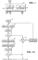
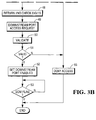
- Figures 3A and 3B show steps in the operation of Figures 1 and 2.
-
- In Figure 1, a host
digital data processor 10 has first and secondoutput data ports upstream data ports second hubs hub 15 has a plurality of downstream oroutput data ports hub 16 has downstream oroutput data ports hub - Each
downstream data port digital data processor 10. Akeyboard 19 has aninput data port 19a connected for data communication with thedownstream port 17c, acard reader 20 has aninput data port 20a connected for data communication with thedownstream port 17b, and adisplay device 21 has aninput data port 21a connected for data communication with thedownstream port 17a. - Each
downstream port hub 16 is also connected to an input or upstream port of a respective peripheral device so as to put the peripheral device into data communication with thedata processor 10. A miscellaneous communicationperipheral device 22 including a telecommunications modem has aninput port 22a connected to thedownstream port 18a. Aprinter 23 has aninput port 23a connected for data communication with thedownstream port 18b, and asecure autoteller subsystem 24 has aninput port 24a connected for data communication with thedownstream port 18c. - It will be noted that the bus system connecting the
data processor 10 and the individual terminals has a tiered star topology where each link segment is point-to point. The use of hubs with one upstream port and more than one downstream port allows the links to fan out to a plurality of peripheral devices. A suitable bus topology for implementing the invention is the Universal Serial Bus (USB). - The
secure autoteller subsystem 24 is situated inside a security enclosure or safe 25. Theinput port 24a of thesubsystem 24 is connected to ahub 26. Thehub 26 has twodownstream ports data input port 29 of acurrency dispenser 30 and thedata input port 31 of adepository 32. Thedata processor 10 can address packets of data to the peripheral devices through the data ports of the hubs. The hubs are adapted to repeat the data packets addressed to them and direct packets to the appropriate downstream port of the hub so as to pass through the tiers of the bus system to reach the required peripheral device. - In Figure 2, the
hub 26 of theautoteller subsystem 24 has ahub repeater 33 connected to theinput data port 24a and thedownstream data ports hub repeater 33 is also connected to ahub controller 34 which controls the data communication through thehub 26. Additional downstream ports are provided as indicated in Figure 2 for data communication with further optional peripherals. Each of the downstream ports of theautoteller subsystem 24 can be in one of a number of logical states. These states include a powered off state, a disconnected state, a disabled state, an enabled state and a suspended state. Transitions between the states are controlled by thehub controller 34 in response to physical power on/off and connect/disconnect events and to commands from thehub controller 34. - In Figures 3A and 3B, the operation of addressing the
secure autoteller subsystem 24 begins at thestarting point 40. Instep 41, thedata processor 10 addresses an access key and an identity code to thesubsystem 24 which is received through theinput port 24a and applied to thehub 26. Thehub controller 34 subjects the digits of the access key and the identity code to a checking algorithm instep 42 to determine whether the access requested by thedata processor 10 is valid. The access key, the identity code and the checking algorithm may take any of a variety of forms which are known in the art. - In
step 43 the result of validation is checked and, if the access request is valid, the hub controller returns an authentication code in the form of check digits to thedata processor 10 instep 44. The data processor subjects the check digits to a processing algorithm instep 45 to formulate and return a hub access request. The hub access request is received by thehub controller 34 and subjected to a second checking algorithm instep 46. The result of the validation instep 46 is checked instep 47. If the hub access request is valid, the hub controller returns a second authorisation code in the form of check digits to thedata processor 10 instep 48. - The
data processor 10 subjects the second check digits to a second processing algorithm to formulate and return a specific downstream port access request instep 49. The port access request is received by the hub controller and subjected to a third checking algorithm instep 50. The result of the validation instep 50 is checked instep 51. If the port access request is valid, thehub controller 34 sets the downstream port selected by thedata processor 10 to an enabled state instep 52. Thedata processor 10 is now in data communication with the selected downstream port of thesubsystem 24 and can communicate operating instructions to the attached peripheral. Thehub controller 34 monitors the data communication passing through thehub repeater 33 and detects instep 53 the end of the communication which is flagged by an end of message flag. - If the
validation step 42 is checked instep 43 and found to result in an unrecognised source of access request, a check is made instep 54 to determine whether more than two earlier such attempts have been made. If this is the third invalid attempt, the check instep 54 results in denial of access instep 55 and the termination of the access operation. On the other hand, if this is the first or second such invalid attempt at access, the hub controller returns a message that the data source has not been recognised and requests a further attempt. - If the validation operation in
step 46 is checked instep 47 and found to result in an invalid hub access request, the access is denied instep 55 and the access operation is terminated. Similarly, if the validation operation instep 50 is checked instep 51 and found to result in an invalid port access request, the access is denied instep 55 and the access operation is terminated. - The data communications between the
data processor 10 and the peripherals connected to the bus system are in encrypted form to provide a first level of security against unauthorised access to the cable links of the bus system. This first level of security applies to the communications to all the peripherals. A second level of security is provided for the peripherals of theautoteller subsystem 24. The second level of security is provided by the enclosure or safe 25 preventing access to the links inside the safe 25 and by the authentication demanded between thedata processor 10 thehub controller 34. The authentication is performed by the exchange of authorisation codes so that a user is correctly identified and the hub access request and the port access request are correctly identified. Because of the tiered star topology of the bus system, information to access individual peripherals is not required to pass serially through all the peripherals and the identity and number of peripherals within the safe 25 can be hidden with enhanced security. - Whilst only one
secure autoteller subsystem 24 has been shown in Figures 1 and 2 it will be apparent that the system may include a plurality of such subsystems connected to thedata processor 10, for example in the arrangement known as a sidecar. Also, in the example, thesecure subsystem 24 has both a dispenser and a depository; in variations, either a dispenser alone or a depository alone could be provided.
Claims (6)
- An automated teller machine characterized by a secure enclosure (25) enclosingan input data port (24a),a hub (26) in data communication with the input port,at least one downstream port (29,31) in data communication with the hub,at least one teller machine utility (30,32) in data communication with a respective downstream port, anda hub controller (34) in data communication with the input port to control data communications from the hub to the downstream port or ports, the hub controller being adapted to authorise access from the hub to a downstream port in response to an exchange of authentication codes between the hub controller and the input port.
- A teller machine as claimed in claim 1, wherein the teller machine utility comprises a cash dispenser (30) and/or a depository (32).
- A teller machine as claimed in claim 1 or 2, wherein the or each downstream port (29,31) is switchable between a plurality of states under the control of the hub controller (34), the plurality of states including an enabled state and a disabled state.
- A teller machine as claimed in claim 1, 2 or 3, wherein the hub controller (34) comprises a processor adapted to validate authentication codes relating to access through the input port to the hub and further authentication codes relating to access through the hub to a downstream port.
- A data processing system including a host data processor (10), a bus including a plurality of hubs (15,16) connected in a tiered star topology, each hub having an input data port (13,14) and a plurality of downstream data ports (17a,b,c, 18a,b,c,) in data communication with the hub, each downstream data port being connected to a respective peripheral (19,20, 21,22,23,26), and at least one of the hubs constituting the hub (26) of the teller machine of claim 1, 2, 3 or 4.
- A data processing system according to claim 5, in which at least two of the hubs constitute a hub (26) of a teller machine of claim 1,2,3 or 4, one hub being arranged as a sidecar.
Applications Claiming Priority (2)
| Application Number | Priority Date | Filing Date | Title |
|---|---|---|---|
| GBGB9811071.1A GB9811071D0 (en) | 1998-05-23 | 1998-05-23 | Automated teller machine |
| GB9811071 | 1998-05-23 |
Publications (3)
| Publication Number | Publication Date |
|---|---|
| EP0959438A2 true EP0959438A2 (en) | 1999-11-24 |
| EP0959438A3 EP0959438A3 (en) | 2002-06-05 |
| EP0959438B1 EP0959438B1 (en) | 2018-08-29 |
Family
ID=10832563
Family Applications (1)
| Application Number | Title | Priority Date | Filing Date |
|---|---|---|---|
| EP99303475.0A Expired - Lifetime EP0959438B1 (en) | 1998-05-23 | 1999-05-04 | Automated teller machine |
Country Status (6)
| Country | Link |
|---|---|
| US (1) | US6196456B1 (en) |
| EP (1) | EP0959438B1 (en) |
| JP (1) | JP4372264B2 (en) |
| BR (1) | BR9901559A (en) |
| GB (1) | GB9811071D0 (en) |
| ZA (1) | ZA993211B (en) |
Cited By (4)
| Publication number | Priority date | Publication date | Assignee | Title |
|---|---|---|---|---|
| CN103383676A (en) * | 2012-07-13 | 2013-11-06 | 威盛电子股份有限公司 | Hub device and method for initializing hub device |
| CN103559162A (en) * | 2013-10-28 | 2014-02-05 | 飞天诚信科技股份有限公司 | Method and host for positioning USB (universal serial bus) devices on HUB set |
| CN107180481A (en) * | 2017-04-01 | 2017-09-19 | 深圳怡化电脑股份有限公司 | A kind of finance self-help traction equipment |
| CN107918315A (en) * | 2017-11-15 | 2018-04-17 | 浪潮金融信息技术有限公司 | ATM control systems and its control method based on Controller Area Network BUS |
Families Citing this family (18)
| Publication number | Priority date | Publication date | Assignee | Title |
|---|---|---|---|---|
| US6546441B1 (en) * | 1993-01-26 | 2003-04-08 | Logic Controls, Inc. | Point-of-sale system |
| US6311165B1 (en) * | 1998-04-29 | 2001-10-30 | Ncr Corporation | Transaction processing systems |
| US7319688B2 (en) * | 2002-05-06 | 2008-01-15 | Extricom Ltd. | LAN with message interleaving |
| US20030206532A1 (en) * | 2002-05-06 | 2003-11-06 | Extricom Ltd. | Collaboration between wireless lan access points |
| US6799054B2 (en) * | 2002-05-06 | 2004-09-28 | Extricom, Ltd. | Collaboration between wireless LAN access points using wired lan infrastructure |
| US20050195786A1 (en) * | 2002-08-07 | 2005-09-08 | Extricom Ltd. | Spatial reuse of frequency channels in a WLAN |
| US20060209771A1 (en) * | 2005-03-03 | 2006-09-21 | Extricom Ltd. | Wireless LAN with contention avoidance |
| US7697549B2 (en) * | 2002-08-07 | 2010-04-13 | Extricom Ltd. | Wireless LAN control over a wired network |
| EP1573631A4 (en) | 2002-12-16 | 2006-08-09 | Peregrin Technologies Inc | A currency dispense and control system with anti-theft features |
| JP2006520137A (en) | 2003-02-18 | 2006-08-31 | エクストリコム リミティド | Multiplexing between access point and hub |
| US20040162037A1 (en) * | 2003-02-18 | 2004-08-19 | Eran Shpak | Multi-channel WLAN transceiver with antenna diversity |
| US7813738B2 (en) * | 2005-08-11 | 2010-10-12 | Extricom Ltd. | WLAN operating on multiple adjacent bands |
| US20080112373A1 (en) * | 2006-11-14 | 2008-05-15 | Extricom Ltd. | Dynamic BSS allocation |
| MY191823A (en) * | 2007-08-03 | 2022-07-18 | Omarco Network Solutions Ltd | A system and a method of handling a multifunction transaction |
| WO2009097464A2 (en) | 2008-02-02 | 2009-08-06 | Peregrin Technologies, Inc. | Remote currency dispensation systems and methods |
| US20090287562A1 (en) * | 2008-02-02 | 2009-11-19 | Peregrin Technologies, Inc. | Anonymous merchant-customer loyalty rewards program |
| US8588844B2 (en) | 2010-11-04 | 2013-11-19 | Extricom Ltd. | MIMO search over multiple access points |
| US9002742B2 (en) | 2013-03-14 | 2015-04-07 | Elisah DUMAS | Computer implemented method for a recycling company to increase recycling demand |
Citations (4)
| Publication number | Priority date | Publication date | Assignee | Title |
|---|---|---|---|---|
| US4902881A (en) * | 1988-06-10 | 1990-02-20 | Faxplus Corporation | Parallel process communications terminal and network |
| DE4442357A1 (en) * | 1994-11-29 | 1996-06-05 | Deutsche Telekom Ag | Protecting data passing between data processing device and terminal device connected via telecommunications network |
| WO1997021199A1 (en) * | 1995-12-01 | 1997-06-12 | Atlantic Richfield Company | System for transacting fuel purchases using an island transaction terminal |
| WO1999061989A1 (en) * | 1998-05-22 | 1999-12-02 | Wave Systems Corporation | Method and system for secure transactions in a computer system |
Family Cites Families (12)
| Publication number | Priority date | Publication date | Assignee | Title |
|---|---|---|---|---|
| AT350822B (en) * | 1976-09-29 | 1979-06-25 | Gao Ges Automation Org | MONEY DISPENSER |
| JPS56111967A (en) | 1980-02-07 | 1981-09-04 | Omron Tateisi Electronics Co | Transaction process system |
| NL8201077A (en) | 1982-03-16 | 1983-10-17 | Philips Nv | A COMMUNICATION SYSTEM, CONTAINING A CENTRAL DATA PROCESSING DEVICE, ACCESS STATIONS AND EXTERNAL STATIONS, WHICH A CRYPTOGRAPHIC CHECK IS FORDICULARIZING AN EXTERNAL STATION, AND EXTERNAL STATIONS FOR USE IN SUCH A COMMUNITY. |
| EP0246823A3 (en) | 1986-05-22 | 1989-10-04 | Racal-Guardata Limited | Data communication systems and methods |
| JP3253335B2 (en) * | 1992-01-20 | 2002-02-04 | 株式会社東芝 | Cash management system |
| US5668876A (en) | 1994-06-24 | 1997-09-16 | Telefonaktiebolaget Lm Ericsson | User authentication method and apparatus |
| US5557778A (en) * | 1994-11-07 | 1996-09-17 | Network Devices, Inc. | Star hub connection device for an information display system |
| US5696824A (en) * | 1995-06-07 | 1997-12-09 | E-Comm Incorporated | System for detecting unauthorized account access |
| US5991546A (en) | 1996-09-17 | 1999-11-23 | Cmd Technology, Inc. | System and method for interfacing manually controllable input devices to a universal computer bus system |
| US6032135A (en) * | 1997-04-29 | 2000-02-29 | Diebold, Incorporated | Electronic purse card value system terminal programming system and method |
| US6000608A (en) * | 1997-07-10 | 1999-12-14 | Dorf; Robert E. | Multifunction card system |
| US6068184A (en) * | 1998-04-27 | 2000-05-30 | Barnett; Donald A. | Security card and system for use thereof |
-
1998
- 1998-05-23 GB GBGB9811071.1A patent/GB9811071D0/en not_active Ceased
-
1999
- 1999-02-26 US US09/259,083 patent/US6196456B1/en not_active Expired - Lifetime
- 1999-05-04 EP EP99303475.0A patent/EP0959438B1/en not_active Expired - Lifetime
- 1999-05-10 ZA ZA9903211A patent/ZA993211B/en unknown
- 1999-05-19 BR BR9901559A patent/BR9901559A/en not_active Application Discontinuation
- 1999-05-20 JP JP14077599A patent/JP4372264B2/en not_active Expired - Lifetime
Patent Citations (4)
| Publication number | Priority date | Publication date | Assignee | Title |
|---|---|---|---|---|
| US4902881A (en) * | 1988-06-10 | 1990-02-20 | Faxplus Corporation | Parallel process communications terminal and network |
| DE4442357A1 (en) * | 1994-11-29 | 1996-06-05 | Deutsche Telekom Ag | Protecting data passing between data processing device and terminal device connected via telecommunications network |
| WO1997021199A1 (en) * | 1995-12-01 | 1997-06-12 | Atlantic Richfield Company | System for transacting fuel purchases using an island transaction terminal |
| WO1999061989A1 (en) * | 1998-05-22 | 1999-12-02 | Wave Systems Corporation | Method and system for secure transactions in a computer system |
Cited By (7)
| Publication number | Priority date | Publication date | Assignee | Title |
|---|---|---|---|---|
| CN103383676A (en) * | 2012-07-13 | 2013-11-06 | 威盛电子股份有限公司 | Hub device and method for initializing hub device |
| CN103383676B (en) * | 2012-07-13 | 2016-07-20 | 威盛电子股份有限公司 | Hub device and method for initializing hub device |
| US9817788B2 (en) | 2012-07-13 | 2017-11-14 | Via Technologies, Inc. | Hub devices and methods for initializing hub device |
| CN103559162A (en) * | 2013-10-28 | 2014-02-05 | 飞天诚信科技股份有限公司 | Method and host for positioning USB (universal serial bus) devices on HUB set |
| CN103559162B (en) * | 2013-10-28 | 2017-01-25 | 飞天诚信科技股份有限公司 | Method and host for positioning USB (universal serial bus) devices on HUB set |
| CN107180481A (en) * | 2017-04-01 | 2017-09-19 | 深圳怡化电脑股份有限公司 | A kind of finance self-help traction equipment |
| CN107918315A (en) * | 2017-11-15 | 2018-04-17 | 浪潮金融信息技术有限公司 | ATM control systems and its control method based on Controller Area Network BUS |
Also Published As
| Publication number | Publication date |
|---|---|
| JP4372264B2 (en) | 2009-11-25 |
| EP0959438A3 (en) | 2002-06-05 |
| GB9811071D0 (en) | 1998-07-22 |
| BR9901559A (en) | 2000-03-21 |
| ZA993211B (en) | 2000-11-10 |
| US6196456B1 (en) | 2001-03-06 |
| EP0959438B1 (en) | 2018-08-29 |
| JP2000029974A (en) | 2000-01-28 |
Similar Documents
| Publication | Publication Date | Title |
|---|---|---|
| EP0959438B1 (en) | Automated teller machine | |
| Rubin | Security considerations for remote electronic voting | |
| EP0186981B1 (en) | Security module for an electronic funds transfer system | |
| US6694436B1 (en) | Terminal and system for performing secure electronic transactions | |
| US20080288790A1 (en) | Means and Method of Using Cryptographic Device to Combat Online Institution Identity Theft | |
| US9246881B2 (en) | Method and system for securing the exchange of data between a client module and a server module | |
| CN101443746B (en) | Method for protecting client and server | |
| US20030005289A1 (en) | System and method for downloading of files to a secure terminal | |
| GB2354102A (en) | System for communicating over a public network | |
| WO2000048062A1 (en) | Communications between modules of a computing apparatus | |
| CN108615154A (en) | A kind of block chain digital signature system and process for using based on hardware encipherment protection | |
| JP2001500999A (en) | Smart card reader with multiple data storage compartments | |
| JP2002517036A (en) | Method and system for transaction security in a computer system | |
| CA2795249A1 (en) | System and method for point-to-point encryption with adjunct terminal | |
| US20130085942A1 (en) | Electronic funds transfer | |
| US20070136589A1 (en) | Identification and authentication system and method | |
| CN107924365A (en) | Anti- hacker's Computer Design | |
| CN101471770B (en) | Method for determining inquiry answer type bidirectional identification and business | |
| JPH0344703B2 (en) | ||
| CN1333610A (en) | Method for identifying user | |
| CN101420299B (en) | Method for enhancing stability of intelligent cipher key equipment and intelligent cipher key equipment | |
| JPH09179951A (en) | Portable information recording medium and its system | |
| CN109347791A (en) | Double I/O bus SIM cards | |
| WO2005069524A1 (en) | Procedure and multi-key card to avoid internet fraud | |
| EP0354771A2 (en) | Personal identification number processing using control vectors |
Legal Events
| Date | Code | Title | Description |
|---|---|---|---|
| PUAI | Public reference made under article 153(3) epc to a published international application that has entered the european phase |
Free format text: ORIGINAL CODE: 0009012 |
|
| AK | Designated contracting states |
Kind code of ref document: A2 Designated state(s): AT BE CH CY DE DK ES FI FR GB GR IE IT LI LU MC NL PT SE |
|
| AX | Request for extension of the european patent |
Free format text: AL;LT;LV;MK;RO;SI |
|
| PUAL | Search report despatched |
Free format text: ORIGINAL CODE: 0009013 |
|
| AK | Designated contracting states |
Kind code of ref document: A3 Designated state(s): AT BE CH CY DE DK ES FI FR GB GR IE IT LI LU MC NL PT SE |
|
| AX | Request for extension of the european patent |
Free format text: AL;LT;LV;MK;RO;SI |
|
| RIC1 | Information provided on ipc code assigned before grant |
Free format text: 7G 07D 11/00 A, 7G 07F 19/00 B |
|
| 17P | Request for examination filed |
Effective date: 20021205 |
|
| AKX | Designation fees paid |
Designated state(s): DE ES FR GB IT |
|
| 17Q | First examination report despatched |
Effective date: 20050627 |
|
| RAP1 | Party data changed (applicant data changed or rights of an application transferred) |
Owner name: NCR INTERNATIONAL, INC. |
|
| REG | Reference to a national code |
Ref country code: DE Ref legal event code: R079 Ref document number: 69945892 Country of ref document: DE Free format text: PREVIOUS MAIN CLASS: G07D0011000000 Ipc: G06Q0020380000 |
|
| GRAP | Despatch of communication of intention to grant a patent |
Free format text: ORIGINAL CODE: EPIDOSNIGR1 |
|
| RIC1 | Information provided on ipc code assigned before grant |
Ipc: G06Q 20/38 20120101AFI20180328BHEP Ipc: G07F 19/00 20060101ALI20180328BHEP |
|
| INTG | Intention to grant announced |
Effective date: 20180420 |
|
| RAP1 | Party data changed (applicant data changed or rights of an application transferred) |
Owner name: NCR INTERNATIONAL, INC. |
|
| GRAS | Grant fee paid |
Free format text: ORIGINAL CODE: EPIDOSNIGR3 |
|
| GRAA | (expected) grant |
Free format text: ORIGINAL CODE: 0009210 |
|
| AK | Designated contracting states |
Kind code of ref document: B1 Designated state(s): DE ES FR GB IT |
|
| REG | Reference to a national code |
Ref country code: GB Ref legal event code: FG4D |
|
| REG | Reference to a national code |
Ref country code: DE Ref legal event code: R096 Ref document number: 69945892 Country of ref document: DE |
|
| REG | Reference to a national code |
Ref country code: GB Ref legal event code: 746 Effective date: 20181101 |
|
| REG | Reference to a national code |
Ref country code: DE Ref legal event code: R084 Ref document number: 69945892 Country of ref document: DE |
|
| PG25 | Lapsed in a contracting state [announced via postgrant information from national office to epo] |
Ref country code: ES Free format text: LAPSE BECAUSE OF FAILURE TO SUBMIT A TRANSLATION OF THE DESCRIPTION OR TO PAY THE FEE WITHIN THE PRESCRIBED TIME-LIMIT Effective date: 20180829 |
|
| REG | Reference to a national code |
Ref country code: DE Ref legal event code: R071 Ref document number: 69945892 Country of ref document: DE |
|
| REG | Reference to a national code |
Ref country code: DE Ref legal event code: R097 Ref document number: 69945892 Country of ref document: DE |
|
| PLBE | No opposition filed within time limit |
Free format text: ORIGINAL CODE: 0009261 |
|
| STAA | Information on the status of an ep patent application or granted ep patent |
Free format text: STATUS: NO OPPOSITION FILED WITHIN TIME LIMIT |
|
| 26N | No opposition filed |
Effective date: 20190531 |
|
| REG | Reference to a national code |
Ref country code: GB Ref legal event code: PE20 Expiry date: 20190503 |
|
| PG25 | Lapsed in a contracting state [announced via postgrant information from national office to epo] |
Ref country code: GB Free format text: LAPSE BECAUSE OF EXPIRATION OF PROTECTION Effective date: 20190503 |