EP0961184B1 - System for use in a field device management - Google Patents
System for use in a field device management Download PDFInfo
- Publication number
- EP0961184B1 EP0961184B1 EP99115002A EP99115002A EP0961184B1 EP 0961184 B1 EP0961184 B1 EP 0961184B1 EP 99115002 A EP99115002 A EP 99115002A EP 99115002 A EP99115002 A EP 99115002A EP 0961184 B1 EP0961184 B1 EP 0961184B1
- Authority
- EP
- European Patent Office
- Prior art keywords
- collection
- block
- items
- fms
- parameter
- Prior art date
- Legal status (The legal status is an assumption and is not a legal conclusion. Google has not performed a legal analysis and makes no representation as to the accuracy of the status listed.)
- Revoked
Links
Images


Classifications
-
- G—PHYSICS
- G05—CONTROLLING; REGULATING
- G05B—CONTROL OR REGULATING SYSTEMS IN GENERAL; FUNCTIONAL ELEMENTS OF SUCH SYSTEMS; MONITORING OR TESTING ARRANGEMENTS FOR SUCH SYSTEMS OR ELEMENTS
- G05B19/00—Programme-control systems
- G05B19/02—Programme-control systems electric
- G05B19/418—Total factory control, i.e. centrally controlling a plurality of machines, e.g. direct or distributed numerical control [DNC], flexible manufacturing systems [FMS], integrated manufacturing systems [IMS], computer integrated manufacturing [CIM]
- G05B19/4185—Total factory control, i.e. centrally controlling a plurality of machines, e.g. direct or distributed numerical control [DNC], flexible manufacturing systems [FMS], integrated manufacturing systems [IMS], computer integrated manufacturing [CIM] characterised by the network communication
-
- G—PHYSICS
- G05—CONTROLLING; REGULATING
- G05B—CONTROL OR REGULATING SYSTEMS IN GENERAL; FUNCTIONAL ELEMENTS OF SUCH SYSTEMS; MONITORING OR TESTING ARRANGEMENTS FOR SUCH SYSTEMS OR ELEMENTS
- G05B19/00—Programme-control systems
- G05B19/02—Programme-control systems electric
- G05B19/04—Programme control other than numerical control, i.e. in sequence controllers or logic controllers
- G05B19/042—Programme control other than numerical control, i.e. in sequence controllers or logic controllers using digital processors
- G05B19/0423—Input/output
-
- G—PHYSICS
- G05—CONTROLLING; REGULATING
- G05B—CONTROL OR REGULATING SYSTEMS IN GENERAL; FUNCTIONAL ELEMENTS OF SUCH SYSTEMS; MONITORING OR TESTING ARRANGEMENTS FOR SUCH SYSTEMS OR ELEMENTS
- G05B2219/00—Program-control systems
- G05B2219/20—Pc systems
- G05B2219/25—Pc structure of the system
- G05B2219/25428—Field device
-
- G—PHYSICS
- G05—CONTROLLING; REGULATING
- G05B—CONTROL OR REGULATING SYSTEMS IN GENERAL; FUNCTIONAL ELEMENTS OF SUCH SYSTEMS; MONITORING OR TESTING ARRANGEMENTS FOR SUCH SYSTEMS OR ELEMENTS
- G05B2219/00—Program-control systems
- G05B2219/30—Nc systems
- G05B2219/31—From computer integrated manufacturing till monitoring
- G05B2219/31098—Configuration editor for networking interconnection
-
- G—PHYSICS
- G05—CONTROLLING; REGULATING
- G05B—CONTROL OR REGULATING SYSTEMS IN GENERAL; FUNCTIONAL ELEMENTS OF SUCH SYSTEMS; MONITORING OR TESTING ARRANGEMENTS FOR SUCH SYSTEMS OR ELEMENTS
- G05B2219/00—Program-control systems
- G05B2219/30—Nc systems
- G05B2219/31—From computer integrated manufacturing till monitoring
- G05B2219/31103—Configure parameters of controlled devices
-
- G—PHYSICS
- G05—CONTROLLING; REGULATING
- G05B—CONTROL OR REGULATING SYSTEMS IN GENERAL; FUNCTIONAL ELEMENTS OF SUCH SYSTEMS; MONITORING OR TESTING ARRANGEMENTS FOR SUCH SYSTEMS OR ELEMENTS
- G05B2219/00—Program-control systems
- G05B2219/30—Nc systems
- G05B2219/31—From computer integrated manufacturing till monitoring
- G05B2219/31326—Database to manage communication networks
-
- Y—GENERAL TAGGING OF NEW TECHNOLOGICAL DEVELOPMENTS; GENERAL TAGGING OF CROSS-SECTIONAL TECHNOLOGIES SPANNING OVER SEVERAL SECTIONS OF THE IPC; TECHNICAL SUBJECTS COVERED BY FORMER USPC CROSS-REFERENCE ART COLLECTIONS [XRACs] AND DIGESTS
- Y02—TECHNOLOGIES OR APPLICATIONS FOR MITIGATION OR ADAPTATION AGAINST CLIMATE CHANGE
- Y02P—CLIMATE CHANGE MITIGATION TECHNOLOGIES IN THE PRODUCTION OR PROCESSING OF GOODS
- Y02P90/00—Enabling technologies with a potential contribution to greenhouse gas [GHG] emissions mitigation
- Y02P90/02—Total factory control, e.g. smart factories, flexible manufacturing systems [FMS] or integrated manufacturing systems [IMS]
Definitions
- the present invention relates generally to database management and, more particularly, to a database management system and method for maintaining a database of transaction records for changes made to parameters of smart field devices within a process.
- process plants include many field devices which control and measure parameters within the process.
- Each field device may be a control device (such as a flow valve controller), a measurement device (such as a temperature gauge, pressure gauge, flow meter, etc.) and/or any other device that affects or determines a value associated with a process.
- control device such as a flow valve controller
- measurement device such as a temperature gauge, pressure gauge, flow meter, etc.
- any other device that affects or determines a value associated with a process.
- field devices have typically been rather simple devices which were controlled either manually or electronically and which produced output readings either electronically or on a gauge connected to the device.
- these devices typically only provide limited information to a controller such as analog signals pertaining to the readings or measurements made by these devices.
- Smart field devices are capable of communicating with a process controller and/or a management system associated with the device.
- Typical smart field devices are capable of transmitting an analog signal indicative of the value associated with the device, for example, a measurement value, and of storing and also digitally transmitting detailed device-specific information, including calibration, configuration, diagnostic, maintenance and/or process information.
- Some smart devices may, for example, store and transmit the units in which the device is measuring, the maximum ranges of the device, whether the device is operating correctly, troubleshooting information about the device, how and when to calibrate the device, etc.
- a smart field device may be able to perform operations on itself, such as self-tests and self-calibration routines.
- Exemplary smart devices include devices which follow the HART (Highway Addressable Remote Transducer) protocol (HART devices), the Fieldbus protocol (Fieldbus devices), the Modbus protocol, and the DE protocol.
- HART devices Highway Addressable Remote Transducer
- Fieldbus devices Fieldbus devices
- Modbus protocol Modbus protocol
- DE protocol DE protocol
- Every conventional and smart device is capable of performing one or more specific input and/or output functions with respect to a process.
- An input function is any function which measures or reads a value associated with a process, such as the function performed by a temperature or pressure measurement device.
- An output function is any function that changes something within a process, such as the functions performed by a valve or flow controller.
- some smart devices such as Fieldbus devices, can perform control functions which are functions associated with the control of a process.
- Each input, output and control sub-function performed by a device is referred to as a "block.” By definition, therefore, each device includes at least one, and maybe more, blocks.
- Fieldbus devices usually include multiple blocks ( e.g. , one or more input, output, and control blocks), and while HART devices do not include blocks, per se, the contents of a HART device are often conceptualized by those skilled in the art as constituting one and only one block.
- Each block (a "conceptual" block) and, therefore, each device includes one or more "parameters.”
- a parameter is an attribute of a block which characterizes, affects or is somehow otherwise related to the block. Parameters may include, for example, the type of the block, the maximum operating or measurement range of a block, the mode of a block, the value of a block measurement, etc.
- each parameter has one or more properties associated therewith, and each of those properties defines or describes the information within the parameter.
- the temperature parameter of a temperature measuring device has a label property which stores the name of the parameter (e.g. , "temperature"), a value property which stores the value of the parameter (e.g. , the actual measured temperature), and a units property which stores the units in which the temperature value is expressed (e.g ., degrees centigrade or degrees fahrenheit).
- a device or a block configuration comprises a set of values for each of the properties of each of the parameters associated with a device or a block.
- HART and Fieldbus protocols allow device manufacturers to provide device-specific types of information for a device and, of course, the particular types of information are different for each type of smart field device. Consequently, these protocols are complex and difficult to use in device programming. More particularly, some of these protocols do not provide a completely consistent method for communicating with every smart device conforming thereto. Instead, these protocols, such as the HART protocol, merely provide a way for device manufactures to specify what information is available from each smart field device and how to retrieve that information.
- DDL device description languages
- DDS device description services
- DDL source files comprise human-readable text written by device developers. These files specify all the information available about a device between the device and a bus or a host to which the device is connected. Basically, in developing a DDL source file for a device, a developer uses the DDL language to describe core or essential parameter characteristics of the device as well as to provide group-specific, and vendor-specific definitions relating to each block, parameter, and special feature of a smart device.
- a DDL source file is compiled into a binary format to produce a machine-readable file known as a device description (DD) which can be provided to a user by the device manufacturer or a third-party developer to be stored in a host system, such as a management system.
- DD device description
- DDL source files may be stored in a smart device and transferred from the smart device to a host system.
- the host system receives a DD object file for a smart device, it can decode and interpret the DD to derive a complete description of the interface with the device.
- DDS is a general software system developed and provided by Fisher-Rosemount Systems, Inc. and/or Rosemount, Inc. for automatically decoding and interpreting the DD's of smart devices. More particularly, DDS is a library of routines which, when called by a host, interprets the DD of a smart device to provide the host with information pertaining to the smart device, including information pertaining to: (1) the setup and configuration of the smart device; (2) communication with the smart device; (3) user interfaces; and (4) methods available for use in conjunction with the smart device.
- One extremely useful application of DDS is in providing a consistent interface between a host system and one or more smart devices having associated DDL source files (and corresponding DD object files).
- DDS, DDL and DD's are generally known in the art, more information pertaining to the specific function and format of DDL's, and of Fieldbus DDL in particular, can be found in the InterOperable Systems Project Foundation's manual entitled “InterOperable Systems Project Fieldbus Specification Device Description Language” (1993), which is hereby incorporated by reference herein.
- a similar document pertaining to the HART DDL is provided by the HART foundation.
- a management system is a system which interacts with one or more smart field devices to read any of the device, block, parameter, variable, or configuration information associated with those devices.
- a management system comprises a personal computer having appropriate communication ports which allow it to interconnect to, communicate with, and reconfigure a smart device.
- Management systems may be on-line, that is, have a hard-wired or other permanent connection with a smart device, management systems may be portable and capable of being periodically connected to a smart device to reconfigure that smart device.
- Management systems typically perform a wide variety of functions with respect to smart devices within a system. For example, management systems may be used to provide users with information (e.g. , values of variables or parameters) pertaining to the state of a process and to each of the smart field devices associated with or connected to the process. Management systems may also be used to enable a user to monitor a process and control the process by reconfiguring smart devices within the process as necessary.
- information e.g. , values of variables or parameters
- the software routines which are used to perform functions within a management system using features provided by the system are typically referred to as applications.
- management systems implement applications provided by individual smart device manufacturers to implement changes on, and read data from, a particular smart device.
- various applications within a management system often do not share a common or consistent interface, and the transition from one application to another is therefore cumbersome and time-consuming.
- smart device configuration data, configuration logs, and smart device diagnostic data created and stored by different applications are decentralized and cannot be cross-referenced because this data may be stored in diverse formats, in different databases and, in some cases, in proprietary formats. Consequently, tasks that could be common to each device within a system must be duplicated in separate applications.
- a management system which implements such separately developed applications typically has no way to view information pertaining to all the smart devices in a plant or a process simultaneously because the applications for each device must be run separately. Furthermore, it is difficult for users to write applications that provide a comprehensive view of data pertaining to multiple, different devices in a process because users typically do not have a great familiarity with DDS or with the DDL and DD's associated with each of the devices within a process. Even if a user does have such familiarity, such applications are time-consuming and expensive to develop and must be updated each time a new smart device is added to the system.
- the management system stored, in an internal "state database," a complete new or current "state” for the device.
- the "state” of a device includes (1) an indication of the time when the change was made (i.e., when the device was put in the new state) and (2) data corresponding to all information stored in the device.
- the state databases of prior management systems may also have included additional information together with the states of devices (e.g ., information about who made the changes to device states or why, etc.).
- multiple on-line management systems are typically interconnected, and data from each system is combined to form a unified historical database reflecting the state of the entire control system.
- the presence of an indication in the records of the multiple interconnected state databases of the time corresponding to each new state does permit reconciliation of the multiple databases to develop such a unified historical database, it does not overcome the well-known inability of prior-art management systems to interface directly with hand-held communicators and to then reconcile data transferred to the management system from hand-held communicators into the management system database.
- Integrated management systems also can be used to reconfigure smart devices more regularly to maintain the certifiability of the process in which the devices are used.
- most management systems which support more than one smart field device include particularized software written for each supported smart device to allow communication with that smart device. Adding a new smart device to a process therefore requires the management system for that process to be reprogrammed. Once again, this programming is time-consuming and can be expensive because it must be performed by a person knowledgeable not only in the management system software, but also in the smart device protocol and the new smart device.
- Another cumbersome aspect of application development is programming an application to perform the numerous tasks relating to and necessary for communication between a user and each smart device within a system.
- a developer not only must be attentive to details involving how to communicate with each separate device, but that developer must also pay particular attention to how information is presented to a user via, for example, a display.
- This task is made more difficult because typical applications do not use consistent user interface protocols.
- Each of these functions requires much programming time and effort, which must be repeated each time a new smart device is added to the system.
- WO 9526527A teaches a control system for controlling auxiliary devices of a printing process.
- a computer-based database management system for managing a configuration database associated with one of a plurality of field devices, each of which has a changeable configuration which includes at least one adjustable parameter.
- the system includes initializing means for setting the adjustable parameter to a first value at a first time, updating means for setting the adjustable parameter to a second value at a second time, and a transaction memory responsive to the initializing means and the updating means for storing a plurality of transactions.
- Each transaction includes a particular value of a particular adjustable parameter and a corresponding time at which the particular adjustable parameter attains the particular value.
- a computer-based database management system for managing a configuration database associated with one of a plurality of devices, each of which has a variable configuration including at least one adjustable parameter.
- the system includes first selecting means for selecting a particular device, second selecting means for selecting a particular parameter of the particular device, assigning means for assigning a particular value for the particular parameter at a particular time, means coupled to the assigning means for communicating the particular value for the particular parameter to the particular device at the particular time, and recording means for creating a transaction record.
- the transaction record includes an identifier uniquely identifying the particular device and further specifies the particular parameter of the particular device, the particular value for the particular parameter, and the particular time at which the particular value is to be applied to the particular parameter.
- the system further includes means for storing the transaction record in a configuration database.
- the present invention is defined by claims 1 to 13 and relate to a field device management system adapted for communication with a field device having device data associated therewith and with a device description storing a subset of the device data therein.
- the system includes means for communication with the field device; means for interpreting the device description to obtain the subset of the device data stored therein; means for initiating a command related to a position of the device data; characterized in that a storing means stores a hierarchy of categories of information associated with the device data, including means associated with each of the categories for defining communication procedures related to the device data associated with that category; a categorizing means categorizes the command as related to one of the categories of the predetermined hierarchy of categories of information; and a controlling means responsive to the categorizing means controls the communicating means and the interpreting means in accordance with the communication procedures associated with one of the categories.
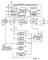
- Fig. 1 illustrates a management system 10, referred to hereinafter as a Field Management Solutions system (an FMS system), interconnected with a process 12, a digital control system 14 (DCS) which controls the process 12, and a further management system such as another FMS system 15.
- the process 12 may comprise any desired type of process, such as a manufacturing or refinery, process, etc., and is illustrated as including four smart field devices, including three HART devices 16, 18 and 20 and one Fieldbus device 22, and a conventional (i.e., non-smart) device 24.
- the devices 16, 18, 20, 22 and 24 are controlled in any desired manner by the digital control system 14.
- the FMS system 10 is a PC-based software tool that includes applications which perform field-device management tasks.
- the FMS system 10 integrates device management for each of the devices within the process 12 by helping users to, for example, configure, calibrate, monitor and troubleshoot any and all of the smart field devices associated with the process 12.
- the FMS system 10 which may comprise any type of computer- or microprocessor-based system, may include a display 30, a printer 31, a keyboard 32 and a mouse 34 connected to an operating system and CPU 36.
- a memory 38 having an FMS database 40 is coupled to the operating system and CPU 36.
- the memory 38, including the FMS database 40 stores software and data used by the FMS system 10 in performing tasks related to displaying information to a user via the display 30 or the printer 31 and communicating with the smart devices 16, 18, 20 and 22.
- the FMS database 40 stores device-related information which is not available from the smart devices, for example, information pertaining to past configurations of the devices, information pertaining to off-line devices, such as off-line smart devices and conventional devices, and information pertaining to service notes including when the next service is needed; who performed service procedures; any favored replacement devices, etc.
- Data pertaining to off-line smart devices may be stored within the database 40 in a format identical to the format in which that data is actually stored within the off-line devices so that, to the FMS system 10, off-line devices appear to be available through the database 40 in the same way they would be available if those devices were on-line.
- the smart devices 16, 18 are on-line devices which are connected to the FMS system via a communication line 42 and a modem 44.
- the smart device 22 is an on-line device which is connected to the FMS system via a Fieldbus Interface 45.
- the smart device 20 is an off-line device which is not permanently connected to the FMS system 10.
- the smart device 20 may communicate with the FMS system 10 via a hand-held communicator and/or secondary (laptop) FMS 46 which, as described in more detail below, may be periodically connected to the device 20 and/or any of the other smart devices to read data from, and write data to, the device 20 and/or the other smart devices. Thereafter, the hand-held communicator and/or secondary FMS 46 may be connected to the FMS system 10 to upload data pertaining to the smart device 20 and/or any other smart devices to which it was attached and store such data in the FMS database 40.
- the operating system and CPU 36 of the FMS system can be connected through, for example, an ethernet communication link 48 and/or other network link to the digital control system 14 and other FMS systems, for example, the other FMS system 15.
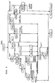
- Fig. 2 illustrates the interconnections between various component parts of the FMS system 10, including hardware and software components, and will be used to describe how the various software components stored in the memory 38 of the FMS system 10 interact with each other, with the display 30, the printer 31, the keyboard 32, the mouse 34, the FMS database 40 and the smart devices within the process 12. It is understood that the software components of the FMS system 10 are stored in the memory 38 and are run on the operating system and CPU 36.
- the FMS system 10 preferably operates in a Microsoft Windows environment (such as a Windows 95TM environment) and, therefore, includes a standard Windows operating system 46, which is used to display data and information on the display 30 and the printer 31 and to retrieve data and information from the keyboard 32 and the mouse 34.
- a standard Windows operating system 46 is preferably provided in a standard Windows call format of any desired type, as is known to those skilled in the art.
- the FMS system 10 could be implemented according to the present invention using any other desired Windows-based or non-Windows-based interface format (whether or not a graphical user interface) including, for example, MacIntosh, Xwindows or IBM DOS formats.
- the FMS system 10 includes a set of FMS applications 50 comprising core applications 52 and add-on applications 54.
- the core applications 52 are essentially programs written by the FMS system provider to perform predetermined and frequently used operations.
- the add-on applications are applications which are developed by a user or a third-party developer and imported to the FMS system 10 to perform customized functions.
- an application refers to any software routine implemented by the FMS system 10 which displays to a user information pertaining to or about the process 12 or one or more devices, blocks, parameters, or other information associated with the devices connected to, or associated with, the FMS system 10, and/or which allows a user to reconfigure one or more of the devices associated with or connected to the FMS system 10.
- the information used by an application typically is either stored in, or developed by, the smart devices within the process 12, or is stored in the FMS database 40.
- the FMS system 10 may include core or other applications which allow a user to interact with the data within the FMS database 40 and/or the smart devices within the process 12 to view the present state of one or more of the devices within the process 12, to change the configuration of one or more of the smart devices within the process 12, to view multiple devices in a simultaneous or sequential manner, to perform common smart device control and configuration functions, to run browsers that locate devices on the network, to monitor the status of devices and generate alarm lists, and to implement device calibration and testing routines.
- a configuration application displays the values of the variables associated with one or more parameters of a device within a process and allows a user to change appropriate ones of those parameter values.
- a configuration management application allows a user to manage the configuration of the device as a whole, for example, resetting a device, initializing a device, and calibrating a device.
- An alarm scanning application checks all of the devices being serviced by the FMS system 10 to determine if those devices are operating correctly or if an error has occurred within any of the devices.
- a history event-log application provides an event log having, for example, user log-in information, time-stamped messages which indicate changes that have been made to the configurations of the devices being serviced by the FMS system 10, alarms associated with the devices being serviced the FMS system 10 and other events.
- a reporting application automatically generates a report showing, for example, all past, present or desired future configurations of one or more devices.
- a trend-analysis or "trending" application records data measured by devices within the process 12 to identify trends which may be occurring within particular devices or across a process as a whole. As is evident, any other desired applications can be created and provided to the FMS system 10.
- a user selects one or more of the applications for execution.
- the selected application is identified in Fig. 2 as the current application or applications 56. Because multiple applications may be executed simultaneously by the FMS system 10, there may be multiple current applications 56.
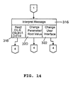
- Any current application 56 may interface directly with the Windows operating system 46, an interface block 58, a digital control interface (DCI) 60 and an FMS database interface 62.
- the current application 56 can also interface with an Open DataBase Connectivity (ODBC) block 64 (a well-known Microsoft database application interface (API) system that enables communication with nearly all databases) and a server network 65. For many applications, however, such connections are not necessary or desirable.
- ODBC Open DataBase Connectivity
- API Microsoft database application interface
- any current application 56 may indirectly interface with the Windows operating system 46, the smart devices within the process 12, and the database 40 via the interface block 58.
- the interface block 58 is essentially a software package having for example, specifically configured Windows custom controls, OCX controls or VBX controls, which automatically perform functions relating to the communication of particular, frequently used information between a current application 56, the smart devices within the process 12, the database 40, and a user interface 65 comprising the Windows operating system 46, the display 30, the printer 31, the keyboard 32, and the mouse 34.
- the interface block 58 can be used by a current application 56 to perform these interfacing functions without the application designer knowing the specifics of the protocols involved therewith. As a result, the interface block 58 enables an application to be designed more easily and provides a consistent user interface.
- current applications 56 and the interface block 58 interface and communicate with the smart devices within the process 12, other FMS systems or digital control systems and/or the database 40 through the DCI 60 and a server network 66 comprising servers 68 and 70.
- server network 66 While typically the server network 66 will be located in, and associated with, the FMS system 10, the dotted line between the DCI 60 and the servers 68 and 70 in Fig. 2 indicates that the DCI 60 can also access server networks of other FMS systems through, for example, the ethernet connection illustrated in Fig. 1.
- the DCI 60 is a convenience layer which comprises a library of routines which perform functions necessary for communicating with, and retrieving data from, and other functions pertaining to the database 40, the smart devices associated with the process 12 and/or other FMS systems.
- the DCI 60 converts commands and messages sent from the current application 56 and the interface block 58 into a format recognized and used by server network 66 and, likewise, converts data provided by the server network 66 into a form recognized and used by the current application 56 and the interface block 58.
- the DCI 60 can use any desired protocol to perform these communication functions, the DCI 60 preferably uses an object-oriented protocol and, most preferably, uses an object linking and embedding protocol such as the Object Linking and Embedding (OLE) protocol developed and documented by MicroSoft, Inc.
- OLE Object Linking and Embedding
- the MicroSoft OLE (2.0) protocol is used in the MicroSoft Windows 95TM operating system and is well-known in the art.
- an object-oriented protocol is a programming paradigm which models the world as a collection of self-contained objects that interact by sending messages.
- Objects include data (a state) and methods (algorithms) that can be performed on the data.
- objects are related to one another through an interface connection and may communicate with other objects in the hierarchy through messages.
- an object receives a message, it responds by using its own methods which are responsible for processing the data in that object and sending messages to other objects to perform specific tasks and possibly return appropriate results.
- the DCI 60 communicates with the server network 66 through an OLE hierarchy
- the DCI uses standard OLE procedures or calls relating to reading and writing values of OLE objects, enumerating a set of enumerated values in an OLE object, getting and setting properties in OLE objects, calling and implementing methods of OLE objects and retrieving property data stored in the OLE collection objects in conjunction with OLE Item methods (a particular type of OLE method).
- OLE procedures can be implemented by the DCI 60 on OLE objects to communicate with the server network 66.
- the particular OLE hierarchy which is preferably used by the FMS system 10 is an OLE object hierarchy which has been developed to categorize all of the different types of information and the interrelationships between the different types of information available for, or used by, each of the different DDL's associated with each of the DD's which, in turn, are associated with the devices within the process 12 being serviced by the FMS system 10.
- This determined hierarchy defines a set of OLE objects, each of which stores a particular set of properties as defined by the hierarchy and a particular set of methods which can be used to manipulate the property data and to communicate with other OLE objects according to the relationships defined by the hierarchy. This hierarchy will be discussed in more detail in conjunction with Figs. 3 and 4.
- the DCI 60 communicates with the server network 66 as if all the OLE objects identified for the determined hierarchy exist within the memory of the server network 66.
- the DCI 60 implements a simple set of calls necessary for communicating with the OLE objects in the OLE protocol. In reality, however, the data and methods of each OLE object are not actually stored or placed in the memory of the server network 66 until a call, such as a read or write call, is sent to the server network 66 for such OLE object by, for example, the DCI 60, the DDS 72, the smart device communication network 74, or the FMS database interface 80.
- the server network 66 recognizes that the data and methods pertaining to the OLE object must be retrieved and stored in memory associated with one of the servers 68 or 70 and automatically performs the functions necessary to retrieve the data and methods of that OLE object.
- the server network 66 When the server network 66 receives a call relating to the reading or writing of data or methods within one of the OLE objects stored in its memory, the server network 66 returns the requested information or performs the requested function to the OLE object data according to its stored routines so as to read data from, and write data to, the OLE object, the DDS 72, the smart devices within the process 12 and the FMS database 40.
- the DCI 60 recognizes or receives changes in OLE objects stored within the memory associated with the server network 66 and performs functions based thereon to implement communication with the current application 56 and the interface block 58.
- the server network 66 interfaces with the OLE objects in the determined OLE hierarchy and includes a device server 68 and a database server 70.
- the device server 68 is essentially a set of software routines which have a specified correspondence with the set of OLE objects in the determined OLE hierarchy. These routines are specifically developed to communicate with a DDS 72, a smart device communication interface 74, and the OLE objects of the defined hierarchy.
- routines may, for example, transmit, retrieve, and change particular types of data and information stored within, or available from, the smart devices within the process 12 and/or from DD's (which are files) associated with the smart devices within the process 12.
- the database server 70 is essentially a set of software routines associated with the OLE objects in the determined OLE hierarchy. These routines communicate with the DDS or API 72 and/or an FMS database interface 80 to, for example, transmit, retrieve, or change particular types of data and information stored within, or available from, the FMS database 40 and/or from the DD's which are associated with the smart devices for which data is stored in the FMS database 40.
- the DD's used by the DDS 72 are stored in a device description library 76 coupled to the DDS library 72.
- the routines of the servers 68 and 70 are associated with each of the OLE objects in such a way that the routines which perform the particular read functions required for retrieving the data of an OLE object from the DDS 72, from smart devices, or from the database 40 are automatically implemented by a request for such data from the DCI 60.
- the routines of the servers 68 and 70 are associated with each of the OLE objects in such a way that the routines which perform the particular writing functions required for changing the configuration of smart devices or storing information in the database 40 are automatically implemented by a request to write such data in the OLE object.
- a request made by the DCI 60 to write the value property within an OLE object representing data within or associated with a smart device will cause the server 68 to implement the routine which writes new property values to the smart device.
- a request to read from any OLE object property values stored in, or associated with, a smart device will automatically call the server routine which retrieves the property values associated with that OLE object from the DDS and/or the smart device and store such property values in the memory (not shown) associated with the server 68 as the OLE object.
- a request made by, for example, the DCI 60 to write the property values within an OLE object associated with data stored in the database 40 will automatically implement the server 70 routine which writes new property values to the locations within the database 40 with which that OLE object is associated.
- a request to read property values from an OLE object will cause the server 70 to retrieve the data associated with that OLE object from the DDS and/or the location in the database 40 associated with those property values and store such property values in the memory (not shown) of the server 70 as the OLE object.
- routines are simple, straightforward, and easy to write by those skilled in the art and thus are not provided herein. However, those familiar with OLE and DDL's can create such routines in a straightforward manner using any desired programming language. If desired, the routines may be written or optimized in any desired way to perform in as high-speed a manner as possible to thereby increase the operating speed of the current application within the FMS system 10.
- the server 68 asks the DDS 72 for the specific data. If that data is stored in the DD for a smart device, the DDS 72 then consults the DD for the referenced device or the DD associated with a block of the referenced device and returns the requested data to the server 68.
- the server 68 stores and maintains that data in the OLE object to which the retrieved data is related. If however, the requested specific data is not available from the DD for a device or a block of a device but is stored, instead, in the on-line device, the server 68 sends a command to the smart device communication interface 74 (which may comprise any known smart device communication interface including, for example, a Fieldbus device interface developed by SoftIng, a German company located in Düsseldorf, or the HART device interface of Micromotion, located in Boulder, Colorado) to retrieve the specific data from the on-line device.
- the smart device communication interface 74 which may comprise any known smart device communication interface including, for example, a Fieldbus device interface developed by SoftIng, a German company located in Düsseldorf, or the HART device interface of Micromotion, located in Boulder, Colorado
- the smart device communication interface 74 then sends a request to the DDS 72 for information on how to get the specific on-line device for the data requested by the server 68.
- the DDS 72 retrieves this instruction information from the DD for the on-line device and returns the instruction information to the smart device communication interface 74 which, in turn, sends a proper request to the on-line smart device.
- the smart device then responds with a data stream including the specific data.
- the smart device communication interface 74 then sends a request to the DDS 72 for information on how to interpret the data stream received from the on-line smart device.
- the DDS 72 then retrieves interpretation instructions from the DD for the on-line smart device and returns them to the smart device communication interface 74 which, in turn, interprets the data stream from the on-line device in accordance with the interpretation instructions in order to extract the specific data requested by the server 68.
- the smart device communication interface then returns the specific data to the server 68 which provides the retrieved data to the OLE object with which that data is associated.
- the process of writing data to an on-line device is similar to the process of reading data from that device except that the server 68 first sends a request to the DDS 72 for write information, e.g. , whether the data is writable, what type, what specific values, and what range of data can be written, etc. If the data is writable, the server 68 sends a write command to the smart device communication interface 74 which, in turn, interfaces with the DDS 72 for write protocols for the on-line device and sends the proper write command to the on-line device in response to the information.
- the smart device communication interface 74 can also interpret other data from the on-line devices, such as write verifications, response codes, data or value changes which occur in the device, etc. and sends such data to the server 68 for storage in the proper OLE object.
- the DDS 72 will inform the server 68 that it needs more information to answer a request for data. For example, the DDS 72 may determine that the handling property of a parameter (i.e. , whether the parameter is readable and/or writable) is dependent on the mode parameter of a particular device.
- the DDS 72 sends a request to the server 68 for the mode parameter of the device.
- the server 68 sends a request for the mode parameter of a device to the smart device communication interface 74 which operates as described above to retrieve the mode parameter of the device.
- the server 68 When the server 68 receives the mode parameter of the device from the smart device communication interface 74, it sends this information to the DDS 72 which, thereafter, determines the handling property of a parameter of a device and returns such property to the server 68 which, in turn, places that value in the proper OLE parameter object.
- Communication between the server 70, the DDS 72 and the FMS database interface 80 is similar to that described above, except that the FMS database interface 80 is programmed to read and write information to and from the FMS database 40 instead of a smart device. Generally, however, the FMS database interface 80 mimics the functions of the smart device communication interface 74 as they relate to communications between the DDS 72 and the server 70.
- the FMS database interface 80 stores information pertaining to, for example, values associated with off-line devices and data pertaining to changes made to on-line and off-line devices in the database 40 in a DDL format, i.e. , in a format that mimics how such data is stored in on-line devices.
- the FMS database interface 80 may need to access the DDS 72 to determine how the data is stored in the FMS database 40.
- the database 40 stores parameter values, such as past parameter values in order to, for example, mimic the state of a device.
- the FMS database interface 80 may have to access the DDS 72 to retrieve this information to know what type of data is stored in the database, i.e., integer, enumerated, etc.
- information stored in the database 40 need not be stored in a DDL format. Therefore, to service a command from the server 70 to read data from, or write data to, the database 40, the FMS database interface 80 may not need to access the DDS 72 for device values. Instead, the FMS database interface 80 may write data to, and read data from, the database 40 directly.
- the FMS database interface 80 is preferably an application program interface (API) of any conventional type which is specifically set up and configured for retrieving information from the database 40 according to any desired or known method.
- API application program interface
- the current application 56 and, if desired, the interface block 58 can also interface with the database 40 through the FMS database interface 62 and the ODBC block 64.
- the FMS database interface 62 may comprise any desired or known applications program interface (API) having a library of routines developed to convert data and requests from a format recognizable or used by the current application 56 into a form recognizable and usable by the ODBC block 64 and vice-versa.
- API applications program interface
- the FMS database interface 62 and the ODBC block 64 will be used when an application needs to store data in the database 40 in a format that is inaccessible or incompatible with the OLE object hierarchy communication scheme discussed herein.
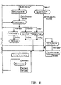
- Figs. 3 and 4 illustrate a particular hierarchy of OLE objects which has been developed to represent all of the information defined within or available from one or more DDL's, a set of smart devices which follow the protocols of those DDL's and a database which stores information related to devices using those DDL's.
- the hierarchy of Figs. 3 and 4 also represents the relationships between those OLE objects. This hierarchy can be used within an OLE environment to enable an application to retrieve information associated with a DDL, smart devices which use that DDL, and a database which stores information pertaining to smart devices which use that DDL.
- the hierarchy of Figs. 3 and 4 represents not only an arrangement of DDL information (i.e.
- Each of the OLE objects in the hierarchy of Figs. 3 and 4 is preferably an OLE automation object and is represented as an oval having the type of OLE object identified therein.
- Each of the OLE objects of Figs. 3 and 4 includes, or is associated with, a subset of the information defined within or used by one or more DDL's and available from DD's, smart devices and databases which store information pertaining to smart devices.
- each of the OLE automation objects of Figs. 3 and 4 includes properties (or attributes), methods and interfaces. Because the OLE objects within Figs. 3 and 4 are automation objects, they have an IDispatch interface (a well-known interface of the OLE protocol) associated therewith.
- the IDispatch of the OLE automation objects of Figs. 3 and 4 can be used by, for example, the DCI 60 and the server network 66 to retrieve information pertaining to the properties and the methods of that OLE object and to communicate with other OLE objects.
- the properties of an OLE object comprise data pertaining to the objects. Each property also has functions which can be used, for example, to get the property value and to set the property value of the OLE object.
- Example OLE object properties include the name of the object, a count of the number of items within or associated with the object, a label associated with the object, and help associated with the object.
- OLE object methods perform actions on OLE objects, or on the data in OLE objects, implement particular routines using the data in OLE objects, and communicate with other OLE objects. For example, a method may enumerate a set of values in other OLE objects.
- the properties and the methods of an OLE automation object define the programmable interface of that OLE object accessible by the server network 66 and the DCI 60.
- the hierarchy of Figs. 3 and 4 comprises an upper hierarchy, illustrated in Fig. 3, and a lower hierarchy, illustrated in Fig. 4.
- the upper hierarchy of Fig. 3 corresponds to and illustrates the physical or defined connectivity of devices such as HART, Fieldbus, and other smart or conventional devices, and blocks, such as Fieldbus blocks, connected within a process.
- the lower hierarchy of Fig. 4 illustrates relationships among the data which is available from, or referenced by, DDL's such as the HART and Fieldbus DDL's, and the data which is stored in and/or available from DD's, smart devices and/or a database pertaining to smart or other devices.
- the OLE Object DDL Equivalents table identifies, for each of the OLE objects illustrated in the lower hierarchy of Fig. 4, the functionally equivalent data, definitions and/or constructs of the Fieldbus DDL that correspond to the OLE object. It should be recognized, however, that the OLE objects of Figs. 3 and 4 similarly have functionally equivalent types of data, definitions, and constructs available in other DDL's, such as the HART DDL, and that the hierarchy of Figs. 3 and 4 therefore can be applied to any DDL.
- Another table (entitled “OLE Object Definitions"), also appearing at the end of the present specification, provides a list of some important properties and methods associated with each of the OLE objects illustrated in Figs. 3 and 4, and provides a short description of those properties and methods.
- the properties of the OLE objects of Figs. 3 and 4 represent, and correspond to, similar types of data available from, or defined by, DDL's (for example, the HART and Fieldbus DDL's) because, as noted above, the OLE objects of Figs. 3 and 4 have been developed to map onto and represent the data available from or defined by these DDL's.
- the Block object of Fig. 3 represents and corresponds to the block entity recognized and used by the Fieldbus DDL
- the Device object of Fig. 3 and the Parameter object of Fig. 4 represent and correspond to the device and parameter entities, respectively, recognized and used by both the HART and Fieldbus DDL's.
- the methods identified in the OLE Object Definitions table are standard OLE methods.
- Root objects define, among other things, the ViewTime to which the data within any of the OLE objects below the Root object pertains. More specifically, the Root object is associated with a ViewTime, which may be "past,” “present,” or “future” and, in some instances, which specifies a particular time. If the ViewTime is present, the time is the actual time. If the ViewTime is past, the time may be set to any historical time but, preferably, is set to a time at which a change was made to one or more parameter values. Preferably these changes are stored in the database 40 in, for example, an event log. If the ViewTime is future, the time may be set to any future time or may be set to indicate only that it refers generally to the future.
- the Item method of the Root object includes a set of collections, as identified in the OLE Object Definitions table, which defines the next layer in the hierarchy of Fig. 3.
- the collections of the Item method of an OLE object define interconnections between that OLE object and the OLE objects below that OLE object within the hierarchy of Figs. 3 and 4.
- Each collection of an Item method of an OLE object is illustrated in the hierarchy of Figs. 3 and 4 by the quoted name of that collection below the OLE object which includes that collection.
- the generic name of the members within a collection are identified in the hierarchy of Figs. 3 and 4 by unquoted and underlined expressions located beneath the OLE object associated with the collection type and above the OLE object which has information pertaining to this expression as one of the properties thereof.
- the Root object has a collection of BlockTag objects (identified as the "BlockTag" collection), each of which has a particular name illustrated generally in Fig. 3 as Block Tag .
- a block tag is a unique identifier assigned to a particular block within the FMS system by a technician installing/configuring the FMS system in order to identify a particular block.
- a BlockTag object having a name of Block Tag therefore, uniquely defines a Block object, as illustrated in Fig. 3.
- the actual number of BlockTag objects within the hierarchy of Figs. 3 and 4 is dependent on the number of blocks (as that name is used in the Fieldbus DDL prctocol) connected to or associated with the FMS system 10.
- the PhysicalTag, DeviceID, and DeviceTag objects relate to or are associated with the "PhysicalTag,” “DeviceID,” and “DeviceTag” collections of the Root object, respectively, and are used to uniquely define a particular device connected to or associated with the FMS system 10.
- a device ID typically includes a triplet of information comprising the name of the device manufacturer, the model number of the device, and the serial number of the device.
- Device tags and physical tags usually refer to a location of the device in a plant or a process such as the process 12.
- the value of a physical tag and/or a device tag can be, for example, an alphanumeric code associated with a specific physical location in the plant or any other description of a physical location.
- the physical tag is considered the same as the device tag whereas, for Fieldbus devices, the physical tag can have a different value than the device tag.
- the OLE objects in Figs. 3 and 4 immediately below a quoted collection name, such as the PhysicalTag object, the DeviceTag object, and the DeviceID object, are also referred to as collections because they are related to constructs which a DDL considers or defines as collections.
- a device can be identified by its physical communication connection to an FMS system. Specifically, each device is connected to an FMS network (illustrated in Fig. 3 by the Network object which is a "Net" collection of the Root object) through one of a number of networks, each of which is identified generically by the expression TCP/IP Node Name .
- Each network includes a series of nodes, identified in Fig. 3 by the NetNode object.
- a network node includes a set of ports (illustrated by the Port object) which may have names of, for example, "Com1" or "Com2".
- the port may connect to a device through a modem (identified by the Modem object) and at one of sixteen station addresses, each of which is identified by a different Station Address .
- the port of a network node may also connect to a device through one or more HART interface units (HIU's) (identified by an HIU object) having a Station Address .
- HIU HART interface units
- Each HIU includes one or more interchanges (identified by the Interchange object) each of which typically includes 8 lines identified by Line Number .
- Interchange objects also include a method (which, contrary to the above-stated general rule about quoted names, is identified by the label "Block") which returns an interface to the particular Block object that describes the HIU.
- a network node can also be coupled to a device through one or more different DCS's, for example, the RS3, Provox, or other DCS's.
- Fig. 3 illustrates each of these as connected through a generic DCS object, the actual connection to an RS3 DCS, for example, would be made and could be identified in Fig. 3 by a node number, a card number, a port (typically one of four ports in a card) and a line (typically four lines per port).
- the configurations of these DCS systems are not yet fully developed, the actual connections with each are not shown and the DCS object is not mentioned in the OLE Object Definitions table.
- a network node may be coupled to one or more Fieldbus interface cards.
- the Fieldbus devices are not yet being sold, the exact connection to a device is not yet known and, therefore, this connection is not represented in the hierarchy of Fig. 3.
- such a Fieldbus connection could easily be added by showing a Fieldbus object and any other OLE objects related to the components required for a Fieldbus connection from between a network node and a device between the NetNode object and the Device object.
- a block within the device can be uniquely determined by the "Tag” collection, illustrated as the Tag object, having the HART Tag name. If the device is a HART device, the contents of which are represented by only one conceptual block, the block is already uniquely identified and can simply be specified by the "HART" collection.
- the names of the tags related to the Tag object are specified as HART Tag in Fig. 3 because the HART tag of HART devices is used as this identifier. However, other tags for other types of devices could be used instead.
- a Block object and, correspondingly, a block of a process can be uniquely identified by traversing any of the above defined paths through the upper hierarchy of Fig. 3.
- every other OLE object within the hierarchy of Figs. 3 and 4 can be identified by a unique moniker derived by traversing a path from the Root object at the top of the hierarchy of Fig. 3 through to the particular OLE object.
- the properties and methods of any of the OLE objects within the hierarchy of Figs. 3 and 4 can be referenced and obtained using the moniker developed for that OLE object.
- a moniker can be determined from the hierarchy of Figs. 3 and 4 by compiling a string comprising the quoted and the unquoted/underlined expressions encountered in traversing a path from the Root object in Fig. 3 to the OLE object of interest, and seperating these expressions with an exclamation point ("!).
- the moniker for a Block object can be any of the following:
- the "NamedConfig" collection of the Root object of Fig. 3 (represented by the NamedConfigs object) relates to objects which are stored in the FMS database 40 and which are not available from a device.
- Each NamedConfigs object is identified by a ConfigName to specify a particular NamedConfig object.
- a NamedConfig object may include, for example, a "recipe" or particular configuration of a block necessary for implementing a particular function within a process, a past configuration of a block within a process, or for that matter, any other desired user information related to Block objects.
- each NamedConfig object looks similar to a Block object except that the parameter value data of a NamedConfig object is retrieved from the FMS database 40 as opposed to being retrieved from a device.
- NamedConfig objects may have a subset of the information typically associated with a Block object.
- each Block object includes a set of collections denominated "Param,” “Unit,” “Database,” “Refresh,” “ItemArray,” “Collection,” “Menu,” “Method,” “EditDisplay,” and “WAO,” each having an associated (although slightly differently named) OLE object.
- Each of these OLE objects in turn, have other OLE objects related thereto as defined in Fig. 4.
- a Parameter object identified by a Param Name may be a VariableParameter object, a RecordParameter object or an ArrayParameter object.
- the EnumerationValues object (a collection of the VariableParameter object for variables of the enumerated type) has particular enumerated values identified by the Enumeration Value object which, in turn, includes a collection of Method objects. These Method objects may, for example, include methods of getting or changing enumerated values of a VariableParameter object.
- the property, data, and methods stored in, or associated with, all of the OLE objects within Fig. 4, except for the DatabaseParameters and DatabaseParameter objects, represent information which is available from or through the use of DD's or a device conforming to a DDL.
- the data and method of the DatabaseParameters objects and DatabaseParameter objects are stored in a database.
- any OLE object in Fig. 4 can be uniquely identified by a moniker developed by tracing a path from the Root object of Fig. 3 down to the particular OLE object of interest.
- the moniker for a pre-edit Method block could be constructed by adding onto the end of the moniker for any Block object of Fig. 3, which is also represented by the Block object of Fig. 4, the expression !param! Param Name !PreEdit! Index .
- the DCI 60 and the server network 66 can, thereafter, operate on and access that OLE object using a shorter unique "handle" generated by the server network 66.
- the handle may, for example, comprise a unique number identifying an OLE object which has been stored in the memory of the server network 66.
- any OLE object identified by the hierarchy of Figs. 3 and 4 can be immediately accessed by the DCI 60 or the server network 66 and the methods within that OLE object can be invoked in order to accomplish communication with the DDS, a database, a smart device, or other OLE objects as necessary.
- the software routine within the server 68 which accesses the DDS 72 to retrieve a particular parameter value from a particular device can be initiated when a call to the proper VariableParameter object is initiated by the DCI 60 using a command which tells the OLE VariableParameter object to read a parameter value.
- the server network 66 communicates with the database 40, the DDS 72, and the on-line devices transparently to the DCI 60 and the current application 56, because the server network automatically accesses the interrelationships between the OLE objects identified by the lower hierarchy of Fig. 4 to determine which set of routines to implement in order to obtain new information requested by an OLE object or a DDS.
- the OLE objects above that OLE object in at least one path between that OLE object and the Root Object Fig. 3 must be stored in the server network memory.
- the Parameter object and the Block object associated with that parameter and that block will also be stored in the server network memory.
- the Device object, the DeviceID object and the Root object may also be stored in the server network memory. Without these higher level objects, the server network 66 can not access enough information to determine how to locate and retrieve the data of the VariableParameter object.
- the DCI 60 sends a command to get a value from an OLE object, for example, the Handling property of a VariableParameter object for a particular block of a particular device using a moniker or a handle which has been provided for that VariableParameter object.
- an OLE object for example, the Handling property of a VariableParameter object for a particular block of a particular device using a moniker or a handle which has been provided for that VariableParameter object.
- the server network 66 uses pre-written routines and the methods of the one or more OLE objects above that VariableParameter object to retrieve this data from, for example, one of the DDS 72, the smart device itself, or the database 40.
- the server network 66 then stores this data in a server memory. If needed the server network 66 first stores for example, the Root object, the DeviceID object, the Device object, the Block object, and the Parameters object, in memory.
- the server uses the methods of the VariableParmeter object and pre-written routines associated therewith to access the DDS 72 (because that is where the Handling information of a variable parameter of a block is located). If, as in this instance, the value of the Handling property of the variable parameter depends on the mode parameter to which the smart device is currently set, the DDS returns a message to the server 68 telling the server 68 that the DDS needs the mode parameter information pertaining to the device or block which contains that variable. At this point, the server 68 locates the Device object related to the VaribleParameter object to determine how to communicate with the device, i.e. , where the device is located in the system and how to interact with that device.
- the server 66 uses a prewritten routine for communicating with the device associated with the Device object to instruct the smart device communication interface 74 to retrieve the mode parameter of the device.
- the server 68 provides this information to the DDS 72 which, thereafter, computes and returns the Handling property to the server 66 which then forwards this information to the OLE VariableParameter object and, thereby to the DCI 60 (because changes in OLE objects result in messages being sent to the host, i.e., the DCI 60 in this case).
- the DCI 60 it merely appears that a request for a read of the Handling property of a parameter was sent to an OLE object and that a message was returned with the Handling property.
- the DCI 60 may thereby operate to communicate with and retrieve information from the OLE hierarchy represented by Figs. 3 and 4 by performing relatively simple routines which, for example, (1) create an object hierarchy and associate it with the server network 66, (2) traverse the object hierarchy to explore the objects below a specified object, (3) implement standard OLE methods like Item , which traverses a specific path from one object to another, and NewEnum , which creates an interface to enumerate objects one level below, (4) implement methods related to Block objects which may include methods related to DDL operations, (5) read and write Root and Device object properties, (6) initiate and control non-blocking read and write requests from OLE objects, (7) retrieve results from blocking reads and writes, (8) control changes to the database 40, and (9) control the creation and maintenance of an event log that includes information pertaining to, for example, user changes to the system including change times, identification of the persons and the computers which made the changes, etc.
- relatively simple routines which, for example, (1) create an object hierarchy and associate it with the server network 66
- an application for the FMS system 10 does not have to be specifically programmed to interface with a DDS, database or smart devices which, in turn, allows an application developer to be much less knowledgeable with respect to DDL formats, DD's and smart device communications.
- any application implemented by the FMS system 10 can interface with FMS devices using, for example, any OLE-compatible programming environment to gain access to the IUnknown and IDispatch interfaces associated with each object in the hierarchy. It is considered that Visual Basic programs and C++ programs are well-suited to use the above-defined OLE hierarchy.
- Figs. 3 and 4 is specifically related to the Fieldbus DDL and to the HART DDL, which is very similar to the Fieldbus DDL, it is considered that this or a similar hierarchy can be made for other DDL's associated with other smart devices including, for example, Modbus smart devices in accordance with the present invention. Furthermore, it is considered that the hierarchy of Figs. 3 and 4 can be implemented by other object-oriented programming protocols and even by non-object oriented programming protocols.
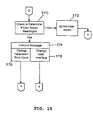
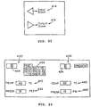
- the FMS database 40 (Figs. 1 and 2) contains a transaction database 200 which the FMS system 10 uses to store data representing changes made to parameters of the various blocks corresponding to devices 16, 18, 20, 22 in the process 12.
- the transaction database 200 is adapted for storing a transaction record 202 corresponding to each parameter change of which the FMS system 10 is or becomes aware.
- Each transaction record 202 includes a number of fields 204-213.
- the fields 204-213 of the records 202 described herein are identified as BlockKey, TimeKey, ParamName, ParamKind, ValueMode, ParamDataType, ParamSize, ParamData, Archived, and Expected.
- the particular contents of the transaction records 202 in the transaction database 200 described herein are only exemplary.
- the records 202 of the transaction database 200 can be adapted to contain any other necessary or desired information relating to the stored transactions, or other information, if desired.
- the meaning of each of the particular fields 204-213 is now described in detail in relation to an exemplary change or transaction comprising the assignment of a particular value (V) to a particular parameter (P) of a particular block (B) at a particular time (T).
- the BlockKey field 204 contains the identifying number of the block to which the change applies, whether the change is a past, present, or future change.
- the identifying number stored in the BlockKey field 204 is a unique number which the FMS system 10 assigns to the block B and uses to uniquely identify the block B.
- the value of BlockKey for a particular block is arbitrary. However, the FMS system 10 must maintain an index (such as in the FMS database 40) of the BlockKeys assigned to all blocks.
- the TimeKey field 205 stores a number, or a collection of numbers, representing the particular time T when the change represented by the transaction record 202 is made.
- the TimeKey could be an actual calendar date and time, expressed with as much precision as is needed ( i.e ., seconds, milliseconds, etc.), or can be a number derived from that information, such as the number of seconds or milliseconds that have elapsed since a particular reference date and time ( e.g ., since January 1, 1980, at 12:00 a.m.).
- the TimeKey for a change could further be expressed in two fields, one containing the date of the change, and the other containing the time of the change.
- the time field could be represented either as an actual time or as a number of seconds (or milliseconds, etc.) elapsed since a reference time.
- the ParamName field 206 contains the name of the particular parameter P of the particular block B to which the change stored by the transaction record 202 relates.
- the names stored in the ParamName fields 206 of transaction records 202 are the actual names of parameters used in the OLE parameter objects of the block B, as described above. Conveniently, these names also correspond with parameter names found in DDL's.
- the ParamKind field 207 contains a single alphabetic character corresponding to the kind of the parameter P.
- the parameter P is an "actual” or “real” parameter, (i.e. , one which affects and/or changes the behavior of a block)
- the ParamKind field 207 contains the value "P.”
- the parameter P is a parameter stored in the database 40 (Fig. 1)
- the ParamKind field 207 contains the value "D.”
- the latter type of parameter is stored only in the database 40 and not in a device. Additional designations of kinds of parameters can also be provided (e.g ., for user-defined parameters or for parameters which contain information about a block but do not affect the block).
- the ValueMode field 208 contains an alphabetic character indicating whether the value "V" of the parameter "P" is part of a "real" state of the device corresponding to the block B, or whether it is, instead, part of a "future” state of that device. Specifically, the ValueMode field 208 contains the value "H” if the transaction record 202 represents part of a real state ( i.e ., if the record 202 represents a past or present change to the block B). On the other hand, the ValueMode field 208 contains the value "F” if the transaction record 202 represents part of a future state ( i . e ., if the transaction record 202 represents a change to be made to the block B at an unspecified time in the future) .
- the numbers corresponding to the various available data types can be arbitrarily assigned by the FMS system 10, but the FMS system 10 must keep track of those assignments.
- the ParamDataSize field 210 contains a number corresponding to the size of the data D stored in the parameter P.
- the value stored in the ParamDataSize field 210 is the number of bytes used to store the data D representing the value of the parameter P.
- the ParamData field 211 in a transaction record 202 stores the actual data or value D assigned to the parameter P by the change represented by the transaction record 202.
- the Archived field 212 is an optional field which stores an indication of whether the contents of the associated transaction record 202 have already been archived or stored to a backup storage medium.
- the Archived field serves to minimize the time required to complete a backup of the database 200 by identifying those transaction records 202 which have already been archived, so that those archived transaction records 202 can be skipped during subsequent archiving procedures.
- the Archived field also provides a safeguard against inadvertent and/or undesired deletion (e . g ., by housekeeping or utility software) of transaction records 202 which have not yet been archived.
- the Archived field 212 of a transaction record 202 contains a one or "true” value if the transaction record 202 has already been archived, and contains a zero or "false” value otherwise.
- the Expected field 213 contains an indication of whether the change or transaction represented by the transaction record 202 was identified by the FMS system 10 that made the change as an "expected" change or an "unexpected” change.
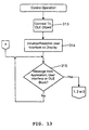
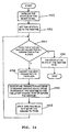
- an FMS system 10 can use the transaction records 202 of the transaction database 200 of the present invention to reconstruct, for any particular time, an expected state of any block of any device in the process 12.
- An "expected" state for a device is the state that an FMS system 10 believes to be the state of the device, based on the transaction history stored in the transaction database 200 of the FMS system 10.
- an FMS system 10 may "expect" a state for a device which is not identical to the actual state of the device. For example, a second FMS system 10, or a hand-held communicator 46, may have changed the state of the device but not yet informed the first FMS system 10 that the change was made.
- the FMS system 10 determines whether the device is in the state that the FMS system 10 "expects" or some other "unexpected” state. If the device is in the state expected by the FMS system 10, then the FMS system 10 makes the change, and stores a one (or other suitable "true” value) in the Expected field 213 of the transaction record 202 corresponding to the change (indicating that the change was expected).
- the FMS system 10 finds the device to be in a state other than the state in which the FMS system 10 expected the device to be, then the FMS system 10 knows that a change has been made which was not reconciled into the transaction database 200 of the FMS system 10. (The procedures by which changes are reconciled into an FMS transaction database 200 are explained in detail below.) In that case, the FMS system 10 enters a transaction record 202 in its transaction database 200 which represents the change that would have to have been made to the device in order to change the state of the device from the state expected by the FMS system 10 to the actual state in which the FMS system 10 found the device.
- the FMS system 10 also stores a zero (or other suitable "false” value) in the Expected field 213 for the transaction record 202 corresponding to that change, indicating that the change was unexpected.
- the Expected field 213 is used by an FMS system 10 (such as a primary FMS) in reconciling transaction records 202 from secondary FMS's and/or hand-held communicators 46 into the primary FMS system 10 as described in more detail below in connection with Fig. 9 and 10.
- the ParamKind field 207, the ValueMode field 208, the ParamDataType field 209, and the ParamDataSize field 210 of a transaction record 202 are included in the transaction record 202 simply to facilitate processing of the data stored in the ParamData field 211 of the transaction record 202, and of the parameter object corresponding to the parameter P as a whole.
- any other suitable information such as the name of the person who made the change, the reason why the change was made, or any other information which may be required by standard plant operating procedures, regulatory requirements, or user preferences, can also be stored in the transaction records 202 of the transaction database 200.
- this additional information can be stored in a second data table similar to the transaction database 200, and including transaction-identifying information (e.g.
- the FMS system 10 then accesses the additional information for each change by cross-referencing to the second data table using the transaction-identifying fields in the particular transaction record 202 representing the change in the transaction database 200.
- the FMS system 10 uses the transaction database 200 to maintain historical records of changes made to smart field devices, e.g. , devices 16, 18, 20, 22, in the process 12; to store current values of parameters in the various field devices; and to store records of future changes to be made to those devices.
- Several specific functions can be performed by the FMS system 10, with respect to the transaction database 200.
- the first function is that when the FMS system 10 (sometimes referred to herein as the primary FMS system) itself makes a change to a parameter of a device or, more particularly, to a specific block of the device, the FMS system 10 adds a record 202 to the database 200 providing all of the above-described information in relation to that change.
- the BlockKey assigned by the FMS system 10 to the block in which the change is made is stored in the BlockKey field 204.
- the TimeKey corresponding to the time at which the change is made is stored in the TimeKey field 205.
- the name of the parameter whose value is changed is stored in the ParamName field 206.
- the kind of that parameter is stored in the ParamKind field 207.
- the mode of the value of the parameter is stored in the ValueMode field 208.
- the type of the data stored by the parameter is stored in the DataType field 209.
- the size of the data stored by the parameter is stored in the ParamDataSize field 210.
- the new value stored in the parameter is stored in the ParamData field 211.
- the Archived field 212 is set to zero, of course, because the transaction record 202, being new, cannot yet have been archived.
- the Expected field 213 is set to one which indicates that the change is an expected one: the change clearly is "expected" because the FMS system 10 authorized and made the change itself.
- the FMS system 10 is not permanently connected to all smart devices in the process 12, because such permanent connections typically are costly to install even though they provide advantages in terms of ease of configuration of the devices by the FMS system 10 to which the devices are permanently connected.
- a so-called transient or temporary connection can be provided between the FMS system 10 and a smart device which is not permanently connected to the FMS system 10, so that the FMS system 10 can make a desired change in the smart device.
- a secondary FMS system 46 can first be connected to the primary FMS system 10 to receive instructions as to what change to make, and the secondary FMS system 46 can then be disconnected from the primary FMS system 10 and connected instead to the smart device so that the secondary FMS system 46 can make the change instructed by the primary FMS system 10.
- the primary FMS system 10 When the primary FMS system 10 sends instructions to a secondary FMS system 46 for making a change, the primary FMS system 10 also sends the "expected" state of the device to the secondary FMS system 46 together with instructions for the change to be made (i.e. , the name of the parameter that is to be changed, and the new value for that parameter).
- a technician takes the secondary FMS system 46 into the field and connects it to the smart field devices 16, 18, 20 and/or 22, etc., of the process, to which changes are to be made and performs the following change-making operation (Fig. 7).
- Fig. 7 depicts a flowchart illustrating how an FMS system 10 interacts with the transaction database 200 when making a change to a smart device 16, 18, 20, or 22 in the process 12.
- the FMS system 10 can change a device only if it is coupled to the device, whether electrically or via any other suitable mode of communication.
- an FMS system 10 can have a permanent connection to a field device or a transient one.
- a transient connection between a secondary FMS system 46 and the FMS system 10 is shown by a dashed line 47 in Fig. 1, and another such connection is shown between a secondary FMS system 46 (which may additionally or alternatively represent a hand-held communicator 46) and a field device 20.
- an FMS system 10 can make changes to the field device by itself. If the device is not permanently connected to the FMS system 10, the FMS system 10 can be used to make a change in the field device in two ways. First, the field device can be transported to the site of the FMS system 10 and interfaced with the FMS system 10 via a transient connection to a serial-interface or other port of the FMS system 10 so that, again, the FMS system 10 can make the change itself. Second, if interfacing the device with the FMS system 10 directly is impractical or inconvenient, a secondary FMS system 46 (Fig. 1) can be transiently connected to, or interfaced with, the FMS system 10 and instructed by the FMS system 10 to make the required changes.
- the secondary FMS system 46 is then disconnected from the FMS system 10 and taken by a field operator to each remote field device in which a change is to be made. The operator connects the secondary FMS system 46 to the field device, and the secondary FMS system 46 makes the change just as would the FMS system 10.
- the FMS system 10 and the secondary FMS system 46 are occasionally referred to as the primary FMS system and the secondary FMS system, respectively. It should be noted that these labels are merely arbitrary designations and that the primary and secondary FMS systems can be equivalent in structure and function, or the secondary FMS system can have reduced functionality compared to the primary, if desired.
- the change-making process begins at a block 220 where the FMS system 10 or 46 connects to the smart field device to which a change is to be made and retrieves the actual state of that device by obtaining values from the device for all of the parameters of the particular block to which the change is to be made.
- a block 222 then compares the actual state of the device to the expected state of the device, which, as described above, was stored in the FMS system 10 before the FMS system 10 was connected to the device.
- the primary FMS system 10 instructs a secondary FMS system 46 to make a change to a device
- the primary FMS system 10 communicates the expected state of that device to the secondary FMS system 46.
- a block 224 causes the FMS system 10 to apply the next change to the device, and a block 226 adds a record of that change to the transaction database 200 (Fig. 5). If the block 222 determines that the actual state of the device is not equal to the expected state of the device, then, before the block 224 applies the change to the device, a block 228 calculates an "unexpected" change and adds a record of the unexpected change to the transaction database 200 so that the transaction database 200 accurately reflects the present state of the device as it exists before the FMS system 10 makes the change.
- the unexpected change is the change that necessarily must have been made (unbeknownst to the FMS system 10) to change the state of the device from the state in which the FMS system 10 expected the device to be, on the one hand, to the actual state in which the FMS system 10 found the device, on the other hand.
- a block 230 permits the operator of the FMS system 10 to make additional changes to the device and, if any such additional changes are made, the FMS system 10 stores transaction records in its transaction database 200 representing the additional changes. These additional changes are identified in the transaction database 200 as "expected" changes.
- a block 232 determines whether the FMS system 10 must make any further changes to the device to which it is connected. If so, control returns to the block 222 to repeat the foregoing process for the next change; if not, the process of Fig. 7 ends.
- the primary FMS system 10 can download change instructions to a hand-held, intrinsically safe communicator 46, such as the Model 275-HC HART Communicator manufactured by Fisher-Rosemount Systems, Inc.
- a hand-held communicator 46 is used by a field operator to take change information to a HART field device located in an area remote from the primary FMS system and/or in a hazardous area where intrinsically safe instrumentation is required (secondary (laptop) FMS systems are unusable in such hazardous areas).
- the operator can connect the hand-held communicator 46 to the smart HART field device to make the changes.
- a hand-held communicator 46 is connected to the FMS system 10, and the FMS system 10 stores a configuration for a particular device in the memory of the hand-held communicator 46, as indicated by a block 240 (Fig. 8).
- a block 240 Fig. 8
- multiple configurations can be stored in the hand-held communicator 46 for multiple devices, if desired.
- the hand-held communicator 46 can receive configuration information from a secondary FMS system 46 in the same manner as it receives configuration information from the primary FMS system 10 as depicted in Fig. 1.
- the hand-held communicator 46 After the hand-held communicator 46 is loaded with configuration information for one or more smart field devices 16, 18, 20, 22, the hand-held communicator 46 is connected to one of the smart field devices where the communicator 46 applies the new configuration for that device to the device as indicated by a block 242.
- a configuration includes all of the same information as a change referred to above in connection with the primary and secondary FMS systems 10 and 46. Further, a configuration can include new values for either some (a partial configuration) or all (a full configuration) of the parameters of a device.
- the difference between a configuration and a change is simply that a configuration, unlike a change, does not include an indication of a time. The reason for this difference is that cost constraints on hand-held communicators 46, and the desire that they be very simple to use, prevent them from providing a timekeeping function.
- the procedure illustrated in Fig. 8 by which a hand-held communicator 46 makes a change to a device is rather simple compared to the procedure illustrated in Fig. 7 by which an FMS system 10 makes such a change.
- the operations that can be performed by a hand-held communicator are rather unsophisticated compared to the operations of an FMS system 10.
- the hand-held communicator 46 can read back the entire state of the device to which it is connected, and return that state to the primary FMS system 10 (or to a secondary FMS system 46), so that the FMS system 10 or 46 can reconcile the new state of the device with the transaction database 200 of the FMS system.
- a plant might require this procedure as part of a standard operating procedure in situations where it is essential to ensure that the changes that an FMS system 10 instructs a hand-held communicator 46 to make are actually made.
- an FMS system 10 communicates a configuration to a hand-held communicator 46
- the FMS system 10 inserts a transaction in its transaction database 200 to reflect the change corresponding to the configuration.
- the transaction record is designated as an expected change, because the FMS system 10 presumes that the hand-held communicator 46 will in fact make the change.
- multiple FMS systems can be interconnected so that data in their respective transaction databases 200 can be merged to form a consistent global view of the plant serviced by the multiple FMS systems.
- This capability facilitates the review of historical information about the operation of a plant, such as by auditors responsible for ensuring the compliance of the plant with the regulatory requirements of various governmental agencies as described above, and also with the guidelines or rules established by plant safety groups.
- Fig. 9 depicts a flowchart illustrating a process by which the transaction database 200 of one FMS system (e.g ., a secondary FMS system 46) can be merged into the transaction database 200 of another FMS system (e.g ., a primary FMS system 10).
- any FMS system can serve as a primary or as a secondary, but the "primary FMS" designation typically refers to a stationary system; secondary FMS systems typically reside in laptop computers which may not always be readily accessible when needed, such as for a compliance audit.
- the labels FMS1 and FMS2 refer to the transaction databases 200 of the primary and secondary FMS systems, respectively.
- a block 250 determines whether any unreconciled transaction records are present in the secondary FMS system 46. If not, or when all unreconciled transactions in the secondary FMS system 46 have been reconciled, the process of Fig. 9 is finished. If unreconciled transactions remain in the secondary FMS system 46 (i.e. , transaction records which have not yet been reconciled into the transaction database 200 of the primary FMS system 10), then a block 252 loads the next unreconciled transaction record (referred to herein as TR) from the memory of the secondary FMS system 46 into the memory of the primary FMS system 10. A block 254 then examines the transaction record TR to determine whether the change represented by that transaction record is an expected change.
- TR next unreconciled transaction record
- a block 256 determines whether the transaction record TR represents the same change as a change which is already present in the primary FMS transaction database FMS1 but which is designated as an "unexpected" change in FMS1. If the change represented by the transaction record TR does not match an unexpected change in FMS1, then the transaction record TR is inserted in the primary FMS transaction database FMS1 in chronological order, and control returns to the block 250 to determine whether any further unreconciled transaction records remain in the secondary FMS system 46. If the change represented by the transaction record TR does match an unexpected change present in the transaction database FMS1, as determined by the block 256, then a block 260 replaces that unexpected change with the transaction record TR (which is an expected change), and control then returns to the block 250.
- a block 264 appends the transaction record TR at the end of the primary FMS transaction database FMS1 and designates the change represented by that transaction record as "unexpected" by setting the Expected field 213 of the record 202 corresponding to that change in the FMS transaction database FMS1 accordingly. Thereafter, control returns to the block 250 to check for more unreconciled transaction records 202 in the secondary FMS system 46.
- a block 266 discards the transaction record TR, inasmuch as the actual change corresponding to the unexpected transaction record TR is already represented by a transaction record 202 in the transaction database FMS1. Again, control thereafter returns to the block 250 to check for more unreconciled transactions in the secondary FMS system 46.
- a primary FMS system 10 instructs a secondary FMS system 46 (S_FMS) to make a future change CF (i.e., a change for which no time is yet specified) to a particular smart field device (refer to the table entitled "Example 1").
- CF future change for which no time is yet specified
- S_FMS secondary FMS system 46
- P_FMS Primary FMS database
- S_FMS secondary FMS database
- i S(i) S(i) S(i) Primary FMS instructs secondary FMS to make change CF to Device.
- S(i) Secondary FMS attempts to make change C(i+1) to Device.
- Prior actual state S(i) of Device matches state S(i) expected by S_FMS so change C(i+1) is made and is recorded in S_FMS designated as "expected.”
- Device is now in state S(i+1).
- the first row of the foregoing table describes the primary and secondary FMS systems in the field device at some arbitrary time i.
- the actual state of the device is S(i), and this state is accurately reflected in the transaction databases 200 of the primary FMS system 10 and the secondary FMS system 46.
- the primary FMS system 10 instructs the secondary FMS system 46 to make a future change to the device. Therefore, at this time, the device remains in the state S(i). Further, the primary and secondary FMS transaction databases P_FMS and S_FMS continue to accurately reflect that the actual state of the device is S(i), but the transaction database 200 of the secondary FMS system 46 now holds a transaction record 202 representing the future change CF.
- the secondary FMS system 46 is connected to the device and attempts to make the future change, designated C(i+1), to the device. Because the secondary FMS system 46 detects that the prior actual state S(i) of the device matches the state S(i) that the secondary FMS system 46 expected for the device, the secondary FMS system 46 makes the change to the device and records in its transaction database S_FMS a transaction record 202 corresponding to the change. Because the change was made to the device, the device is now in state S(i+1), and because the transaction record for that change (which, incidentally, is designated as an expected change in the transaction database 200), the expected state of the device reflected in the transaction database 200 of the secondary FMS system 46 is also updated to S(i+1). However, because the primary FMS system 10 has not yet been informed that the secondary FMS 46 has successfully made the future change CF, the primary FMS system 10 maintains S(i) as the expected state for the device.
- the primary FMS system 10 reconciles that transaction record into its primary FMS transaction database 200 as described above in connection with the process of Fig. 9. Specifically, because the incoming transaction record was designated as an expected change, and because the change had not yet been entered in the primary FMS transaction database 200 as an unexpected change (presuming that it really had not been), the transaction record for the change C(i+1) is entered into the primary FMS transaction database 200 in chronological order by the block 258 (Fig. 9) such that the expected state of the device as now reflected by the transaction database 200 of the primary FMS system 10 accurately reflects the actual state of the device, namely S(i+1).
- Example 2 Occurrence Time P_FMS S_FMS1 S_FMS2 Device Primary FMS database (P_FMS) and secondary FMS databases (S_FMS1 and S_FMS2) accurately reflect actual state of Device.
- P_FMS Primary FMS database
- S_FMS1 and S_FMS2 accurately reflect actual state of Device.
- Secondary FMS2 instructed to make future change CF to Device.
- a primary FMS system 10 and two secondary FMS systems 46 accurately reflect the actual state S(i) of a device at an initial time i.
- the primary FMS system 10 instructs the first secondary FMS (FMS1) to make a change C(i+1) to a device. Also at that time, the primary FMS system 10 instructs the second secondary FMS (FMS2) to make a future change CF to the same device. Therefore, at time i+1, the transaction databases 200 of the primary FMS system and the first and second secondary FMS systems accurately reflect the actual state S(i+1) of the device. In addition, a record of the change C(i+1) is stored in the first secondary FMS system 46, and a record of the future change CF is stored in the second secondary FMS system 46.
- FMS1 makes the change C(i+1) to the device according to the procedure described above in connection with Fig. 7. Consequently, at this time, FMS1 accurately reflects the actual state S(i+1) in its transaction database 200, while the primary FMS PFMS and the second secondary FMS FMS2 continue to reflect the prior state S(i) of the device in their respective transaction databases 200. Also, FMS2 still holds a transaction record for the future change CF which has not yet been made.
- FMS2 attempts to make the future change CF to the device and detects that the device is in an unexpected state S(i+1) (i.e., a state other than the state S(i) which the transaction database 200 of the FMS2 reflects). FMS2 therefore computes the unexpected change CU that must have been made to change the device state from S(i) (expected by FMS2) to S(i+1) (the actual state of the device). FMS2 then records a transaction record corresponding to the unexpected change CU in its transaction database 200 and then makes the future change CF to the device and records a transaction record corresponding to the change CF together with a current TimeKey in the transaction database 200 of FMS2. Therefore, the transaction database 200 of FMS2 now accurately reflects the current state S(i+2) of the device, and the transaction database 200 of FMS2 further includes a record of the unexpected change CU which FMS2 recognized to have been made to the device.
- S(i+1) i.e., a state other than the state S(i) which the transaction
- the secondary FMS system FMS2 is connected to the primary FMS system 10 and reports the unexpected change CU and the now-made, authorized change C(i+2) to the primary FMS system 10.
- the transaction records for these two changes are then reconciled by the primary FMS system 10 into its transaction database 200 according to the procedure of Fig. 9, so that the transaction database 200 of the primary FMS system 10 accurately reflects the actual state S(i+2) of the device and includes transaction records corresponding to the changes CU and C(i+2).
- the primary FMS FMS1 still reflects that it expects a state of S(i+1) for the device, while the secondary FMS FMS2 accurately reflects the actual state S(i+2) of the device.
- FMS1 is connected to the primary FMS system 10 and reports change C(i+1) thereto.
- the primary FMS system 10 reconciles the transaction record for change C(i+1) into its transaction database 200 and finds that C(i+1) matches the unexpected change CU entered into the transaction database 200 of the primary FMS system 10 during time i+4. Therefore, in accordance with the block 260 (Fig. 9), the transaction record for the change C(i+1) replaces the transaction record for the unexpected change CU in the transaction database 200 of the primary FMS system 10.
- the interface block 58 calls the interface block 58 to initialize one or more specific controls which, thereafter, automatically handle all operations associated with interfacing between the Windows operating system 46, the smart devices within the process 12 and/or the FMS database 40 with respect to a device, a block, or a parameter associated with the process 12.
- the interface block 58 may also change the Time property of the Root object stored in the memory of the server network 66 to control displays in an advantageous manner.
- Each control of the interface block 58 displays and updates information pertaining to a device, a block, a parameter, or a time on the display 30; and communicates with the smart devices, the database 40, and the server network 66 in response to user or application inputs to retrieve data from, or write data to, the DDS 72, the smart devices, the database 40, or the Root object in the server network 66, without further involvement of the current application 56.
- a control generally appears to run independently of the current application 56 and of other controls which may have been established.
- the interface block 58 includes a master control routine 300 which can be used to implement control functions, including control functions relating to a device, a block, or a parameter associated with the process 12.
- the interface block 58 also includes a master timeline control routine 301 which can be used to implement control functions such as reading and writing times from the Root object and changing time values from the database 40.
- one of the master control routines 300 or 301 is, in effect, copied and converted into a specific control routine or control.
- Such specific controls are illustrated in Fig. 11 as a device control 302, a block control 304, a parameter control 306 and a timeline control 308.
- the specific controls 302, 304, 306, 308 thereafter automatically handle functions related to communication between the Windows operating system 46, the current application 56, the database 40 (through the DCI 60), the DDS 72 (through the DCI 60), and the on-line smart devices (through the DCI 60) as those communications relate to the specific devices, blocks, parameters, or timelines for which the controls are created.
- each of the controls 302, 304, 306, 308 operates continuously and independently of the other controls and the current application 56. Any number of the same and/or different control types can be implemented to operate at the same time.
- Fig. 11 illustrates the controls 302, 304, 306, 308 as separate routines which are copies of one of the master control routines 300 or 301
- controls 302, 304, 306, 308 can also contain the data necessary to implement a particular device, block, parameter, or timeline control using one of the master control routines 300 or 301.
- Fig. 12 generally illustrates the steps that should be performed by, for example, the current application 56 to initialize a control, including any of the controls illustrated in Fig. 11.
- a block 310 defines the type of the control, for example, a device, a block, a parameter, or a timeline control, by providing the interface block 58 with a unique moniker pointing to the OLE object within the hierarchy of Figs. 3 and 4 with which the control is associated. Because, conceptually, an instantiation of the hierarchy of Figs. 3 and 4 exists for each time available to the FMS application, the timeline control specifies the Root object of a particular hierarchy by specifying, for example, the time and view of the Root object with which the control is associated.
- a block 311 defines the user interface attributes including, for example, the fonts, sizes, etc., of display characters, the style in which the information is to be displayed, the display screen location at which the control information is to be displayed, the initial window size of the control display if the size of a control display is capable of being changed by the user, and the so-called "visibility" of the control.
- Control visibility defines whether the control will actually be displayed or be visible on the screen. While an invisible control still operates to retrieve data from its associated OLE object and may provide such information to the current application 56, the user interface operations of that control are simply disabled.
- a block 312 defines the refresh rate of the control (i.e., the rate at which the control will receive information from its associated OLE object in a periodic read).
- the block 312 connects the control to a particular Root object of the hierarchy in Figs. 3 and 4, and the Root object defines the rate at which the OLE object will refresh data in response to a periodic read.
- Fig. 13 illustrates the general operation of a control routine which can be used for the device control, the block control, the parameter control and the timeline control of Fig. 11.
- a block 313 connects to or establishes a connection to the proper OLE object as defined by the hierarchy of Figs. 3 and 4 and the moniker provided by the current application 56.
- the control sends a command through the DCI 60 to the server network 66 to read information, for example, the properties, of the OLE object associated with the control.
- this command is a periodic read which tells the OLE object, such as a device, a block or a parameter object, to periodically send the requested data to the control.
- the server network 66 establishes a connection to the OLE object by retrieving the data thereof from the DDS 72, the smart devices and/or the database 40, and stores that data as the OLE object in a server network memory.
- the server network 66 must also store in its memory the data pertaining to the Device and/or Block objects above the requested OLE object as defined by the hierarchy of Figs. 3 and 4.
- the requested OLE object data is sent to the DCI 60 and then to the interface block 58 where this data may be stored in a memory or control cache associated with the interface block 58.
- a block 314 then establishes or initializes a user interface screen on the display 30 for the particular control as defined by the user interface attributes provided to the control by the block 311 of Fig. 12.
- the display attributes may be configured to display control information in any desired manner using standard Windows calls and Windows formats.
- An exemplary screen for each of the device, parameter, block, and timeline controls is illustrated in Figs. 20-22.
- a block 315 checks to see if any messages have been received from the application, the user interface via the Windows operating system 46, or an OLE block through the DCI 60. If no such messages have been received, the block 315 continually rechecks for such messages. When the block 315 receives a message, control is transferred as indicated by the identifiers labeled 1, 2, and 3.
- Fig. 14 illustrates the operation of a control in response to a message from the current application 56.
- a block 316 interprets the message which can be of three general types, including a read OLE object data message, a change Parameter object value, or a Root object value message and a change user interface message.
- a block 318 reads the requested data from the referenced OLE object of Figs. 3 and 4.
- a device control may read the DeviceID property or the "Tag" collection of a Device object while a block control may read the Name property or the "Param" collection of a Block object.
- a parameter control might read parameter properties such as the value or name of a VariableParameter object.
- a timeline control can read Root object properties and may obtain a list of times for which Root objects exist in the past from the database 40. Thereafter, the block 318 returns control to the block 315.
- a block 320 implements a change to the referenced parameter object, for example, the VariableParameter object, RecordParameter object, or ArrayParameter object of Fig. 4 and returns control to the block 315.
- a block 322 implements a change of the user interface and returns control to the block 315.
- Fig. 15 illustrates a routine 324 which is implemented by a control during a read OLE object data procedure.
- a block 326 sends a message through the DCI 60 to the OLE object associated with the control to retrieve data from that OLE object.
- a block 328 determines what type of read message was received. If a non-blocking, non-periodic or a non-blocking, periodic read message was received, the block 328 returns control to the block from which the routine 324 was called.
- a non-blocking read refers to one in which the control sends a read message to the OLE object associated with the control and does not wait for a response from the OLE object before continuing with other functions.
- a non-periodic read is a request for a single, one-time read from the OLE object associated with the control.
- a periodic read instructs the OLE object to periodically notify the control of changes which occur to data within the OLE object at a rate defined within the Root object associated with that OLE object.
- a block 330 waits for the return data requested from the OLE object.
- a block 332 stores the received OLE object data in the control cache.
- a block 334 changes the user interface by calling a user interface change routine described hereinafter to reflect the new data obtained by the read.
- a block 336 notifies the current application 56 if the application has identified that it wants to receive messages or data changes from OLE object data reads during, for example, initialization of the control. Thereafter, control is returned to whatever block called the routine 324.
- Fig. 16 illustrates a routine 338 which is implemented by a control during a change of a parameter or root value of an OLE parameter object (such as the VaribleParameter object) or a Root object.
- a block 340 determines whether the parameter or root value indicated to be changed is writable. In essence, the block 340 sends a message to read the handling properties of the OLE object and determines whether the parameter value is writable. If the block 340 determines that the parameter or root data value is not writable, a block 342 notifies the user or the current application 56 that the parameter or root value is not writable, such as by calling the change-user interface routine described below. Thereafter, control is returned to the block from which the routine 338 was called.
- a block 344 determines if the new parameter value (or root value) is an accepted value. To perform this function, the block 344 reads, for example, the value characteristics of the parameter object associated with the control such as the minimum value, the maximum value and the type of value accepted which may be, for example, a variable, an enumerated set, etc. If, thereafter, the block 344 determines that the new value is out of range or of the wrong type, a block 346 may send a message to the application and/or may change the user display to indicate that an unacceptable value has been entered. Thereafter, control is returned to the block which called the routine 338.
- a block 348 sends a change message to the correct OLE parameter or root object through the DCI 60.
- the new value is then changed in the OLE object which, of course, may cause a corresponding change in a smart device or in the database 40.
- a block 350 waits for a return message and a block 352 decodes the return message to determine if the write was successful. If the write was successful, a block 354 may indicate to the application and/or to the user via the user interface that the change was made ( e.g. , by changing the color of the background of the data on the screen).
- a block 356 indicates to the application and/or to the user via the user interface that the change was not made (e.g. , by changing the data on the screen to its original state).
- the response codes associated with an OLE object are always available to an application so that the reason for the rejection can be determined and/or displayed to the user.
- a block 358 retrieves a response code from the OLE object by specifically initiating a proper read from the OLE object.
- a block 360 then indicates to the application, and/or to the user if desired, that the change was made but that a write condition exists.
- the block 360 may also indicate the type of condition that exists (e.g. , that the OLE object property was set to the nearest available possible value).
- Each of the blocks 354, 356, and 360 returns control to the block which called the routine 338.
- Fig. 17 illustrates a routine 362 which is implemented by a control to change the user interface display.
- a block 364 changes the display interface attributes in conjunction with new attributes provided by the current application 56, or in accordance with a set of attributes previously defined by the control for the condition which now exists. These previously defined attributes may be stored in a memory associated with the control, such as the control cache.
- a block 366 refreshes the user display using the new user display attributes and the data in the control cache which is to be displayed. Thereafter, control returns to the block from which the routine 362 was called.
- Fig. 18 illustrates the operation of a control in response to a message from the user interface.
- a block 370 checks to determine if the user action is meaningful. The block 370 may, for example, determine if the user clicked the proper button of the mouse or if the pointer (i.e., the cursor or arrow) was located within an area of the control display where the control recognizes the user's actions as requests for action. If the user action is not meaningful, a block 372 simply ignores the user action or gives some indication that the action has been ignored (e.g ., refreshing the user display with the same display interface attributes). Thereafter, control is returned to the block 315.
- the pointer i.e., the cursor or arrow
- a block 374 interprets the message from the user interface. If the message from the user interface indicates that the user would like to change a parameter value or a root value, a block 376 calls the change-parameter/root-value routine 338 and then returns control to the block 315. If desired the block 376 may also change the user interface, for example, to implement a color change to the background field surrounding the data to be written. Upon receiving an indication of a successful write, the block 376 may also return the background color to its original state to indicate that the value has been written (if the routine 338 has not already done so).
- a block 378 calls the change-user-interface routine 362 and returns control to the block 315.
- Fig. 19 illustrates the operation of a control in response to a message from the DCI 60, i.e. , from an OLE object within the hierarchy of Figs. 3 and 4.
- a block 380 first determines if the message from the DCI 60 is non-blocking read return or if the message indicates some other change or changed condition within the referenced OLE object of the OLE hierarchy.
- a condition-change message may, for example, comprise an FMS locking message which prevents multiple users from accessing a particular block within a device of a process at the same time. If, for example, a block is being accessed by a different user by a hand-held communicator or another FMS system attached to the device, the OLE object will identify such condition to the control through the DCI 60. Thereafter, the control may indicate to the user that the data of that block is no longer writable by, for example, displaying a gray background on the screen surrounding a normally writable value.
- a block 382 determines if the returned value has changed. If so, a block 384 stores this new value in the control cache. The block 384 and, if there has been no change in the data stored in the control cache, the block 382 as well, provides control to a block 386. The block 386 is also implemented if the block 380 determines that the message from the OLE object relates to a change not related to a non-blocking read.
- the block 386 determines if a change to the user interface is needed, such as if the changed data or the new condition or status is to be displayed on the screen. If so, a block 390 calls the change-user-interface routine 362 to display the changed data or the condition to the user. If, however, the block 386 determines that the changed data or the condition does not need to be displayed, or if the block 390 has indicated such changed data or condition to the user, a block 392 determines if the application should be notified of the changed data or condition in accordance with pre-written instructions. If so, a block 394 sends a message to the current application 56 indicating the changed data or condition. Thereafter, control is returned to the block 315.
- information accessed by a device, a block, a parameter, or a timeline control can be displayed on a screen in any desired manner including (1) the EDIT style wherein the control behaves similarly to a normal Microsoft Windows Edit control, (2) the COMBO style wherein the control behaves similarly to a normal Microsoft Windows Combo Box control ( i . e ., as a drop down list), (3) the LIST style wherein the control behaves similarly to a normal Microsoft Windows List Box control ( i.e.
- Fig. 20 illustrates control displays 400 and 402 associated with two device controls.
- Each of the device control displays 400 and 402 includes a picture or digital bitmap of the device (usually provided by a device manufacturer or the DDS provider), which is stored in a memory associated with the current application. Instead, this bitmap may be stored in the database 40 so as to be accessible by the OLE objects.
- the control displays 400 and 402 may include any other desired information about a device including, for example, the name (illustrated in Fig. 20), tags, moniker, etc. of a device, or any other desired device-specific information.
- menus for the device can be provided in a pull-down window associated with the device control displays 400 and 402.
- Such menus may include files associated with a device, for example, the names of the collections associated with a Device object for the device, methods which can be implemented on the device, including calibration, resetting, and self-testing methods, blocks associated with the device, a list of parameters associated with the device, help for the device, service notes for the device, etc.
- Other information about a device which may be displayed includes the contents of every variable of each parameter in a device, the face-plate information of a device, the operational status of the device, including, for example, whether an error has occurred within the device and a side-by-side list of, for example, the values of variables of one or more parameters of a device as they exist or existed at specified times.
- Fig. 21 illustrates a general parameter control display 406 along with particular parameter control displays 408, 410, and 412 associated with three specific parameter controls for the parameters of a device.
- Each of the parameter control displays 406-412 is located at a different portion on a screen and, in particular, the parameter control display 406 is located at the top of the screen while the parameter control displays 408, 410 and 412 are located in sequence below the parameter control display 406.
- the parameter control display 406 illustrates that a parameter control display may have three fields, including a label field, which provides information pertaining to the type of information being shown, for example, "Pressure,” “Temperature,” or “Mode,” a value field which shows the value of a parameter and a units field which indicates the units in which the value is expressed.
- the value of a parameter can be an integer number, a decimal number (parameter control displays 408 and 410) or an enumerated value consisting of one of an enumerated set of values, as listed in a pull-down menu associated with the parameter control display 412.
- the parameter control display 412 does not include a units variable because such a variable is inapplicable to the enumerated set associated therewith.
- Fig. 22 illustrates two block control displays 414 and 416 associated with block controls. Similar to a device control display, a block control display typically includes a picture or other representation of a block and/or any other desired information pertaining to a block and/or the device in which the block is located including, for example, whether a block is an input, output, or control (or interface) block.
- Fig. 23 illustrates two timeline control displays 420 and 422 which are used to control and change the time and view properties of OLE Root objects to which other controls, such as device, block, and parameter controls may be connected.
- Each of the timeline controls associated with the displays 420 and 422 can change the time value of its respective Root object to any of the previous times for which Root objects are available, which will typically include the past times when changes were made to the system and for which transaction records 202 are stored in the transaction database 200 (Fig. 5) of the FMS database 40 (Fig. 1).
- the timeline controls associated with the control displays 420 and 422 can change the view of a Root object between a past, a present, or a future setting.
- Each timeline control display usually includes, as illustrated in Fig. 23, a slider 424 indicating which one of the past, present, and future views is selected as well as a combo box 426 which allows a user to select from a set of historical times, each having, for example, a date and a time.
- timeline control slider 424 By changing the timeline control slider 424, the user tells the timeline control to change the Root object View property associated with that timeline control.
- timeline control combo box 426 By changing the timeline control combo box 426, the user tells the timeline control to change the Root object time value to a specified time.
- any other controls such as parameter, device or block controls which are associated with that Root object will automatically be updated in response to change messages generated by the OLE objects.
- Change messages will be generated by the OLE objects when the OLE objects within the same hierarchy as the Root object retrieve new data pertaining to the new time or view now associated with the Root object.
- Fig. 23 also illustrates temperature- and pressure-parameter control displays 430 and 432 which are connected to the same Root object as the timeline control associated with the timeline control display 420.
- temperature and pressure parameter control displays 440 and 442 are connected to the same Root object as the timeline control associated with the timeline control display 422. Because the timeline control displays 420 and 422 are set to different times, i.e., a past time (control display 420) and the present (control display 422), the values of the temperature parameters 430 and 440 are different and the values of the pressure parameters 432 and 442 are different.
- a list of such parameter control displays can be configured on the screen to display one or more complete configurations for a device, block, etc.
- Device and block and/or other parameter controls can also be associated with the same Root object as timeline controls and can be used to illustrate a configuration display which shows a configuration of a device, a block, or a parameter at different times in a side-by-side or other relationship on a screen.
- a timeline control can also be used in conjunction with other controls on a display to scroll through the settings or values of devices, blocks or parameters or a set of such device, blocks, or parameters.
- any desired combination of timeline, device, block, parameter and/or other controls may be used to illustrate any desired past and or present information to a user including, for example, information related to on-line devices at the present time, i.e., on-line data, and information related to on-line devices in the past or future, and to off-line devices in the past, present or future, i.e., off-line data.
- information related to on-line devices at the present time i.e., on-line data
- information related to on-line devices in the past or future i.e., off-line data.
- off-line devices in the past, present or future i.e., off-line data.
- the same data for example, the same parameter values for a device, may be illustrated for different times using timeline controls and, if desired, routines may be implemented to indicate the differences between the sets of values.
- the timeline control changes the Time property of the Root object to a specific time (designated hereinafter as the ViewTime), which the user specifies using the timeline control. Consequently, the time attributes for all of the objects downstream of the Root object in the OLE hierarchy are changed to match the ViewTime as described above. In addition, the values of other properties of those objects are updated to the values corresponding to that ViewTime.
- the state of the corresponding block at any desired time is obtained using the above-described transaction database 200 (Fig. 5). More particularly, the values of the parameters of the Block object at the ViewTime (i.e., the values of the Value properties of the Parameter objects of the Block object as of the ViewTime) are obtained by searching the transaction database 200 in reverse-chronological order beginning at the ViewTime to find the values last assigned to the parameters corresponding to those Parameter objects on or before the ViewTime. This procedure is now described in detail with reference to the flowchart of Fig. 24.
- Fig. 24 is a flowchart illustrating how a state of a particular block can be reconstructed from the transaction database 200 described above.
- a block 450 initializes a "set"-type variable ⁇ S ⁇ to null.
- the set variable ⁇ S ⁇ is used to accumulate the values as of the ViewTime of the parameters of the block whose ViewTime state is to be reconstructed.
- a block 452 sets a time associated with the set or state ⁇ S ⁇ equal to the ViewTime.
- a block 454 determines whether the set variable ⁇ S ⁇ includes a value for each parameter of the Block Object. If it does, then a block 456 assigns the assembled state ⁇ S ⁇ as the state of the block at the ViewTime, and execution of the state reconstruction routine of Fig. 24 ends.
- a block 458 identifies the next parameter P for which a current value is not included in the accumulated state ⁇ S ⁇ .
- a block 460 searches the transaction database 200 in reverse-chronological order beginning at the ViewTime to find the latest-made change TR made at or before the ViewTime.
- a block 462 adds the parameter P, with the value of the parameter P set by the change represented by transaction TR, to the accumulated state ⁇ S ⁇ , and control then returns to the block 454 to check, once again, whether values of all parameters in the block have now been accumulated in the state ⁇ S ⁇ .
- the DDL equivalent is an array , which is a logical group of values. Each value, or element, is of the data type of a DDL variable. An element may be referenced from elsewhere in the device description via the array name and the element index. DDL arrays describe communication array objects. Therefore, from a communication perspective, the individual elements of the array are not treated as individual variables, but simply as individual values.
- Block object The DDL equivalent is a block, which defines the external characteristics of a DDL block. Collection object This OLE object represents a particular object in the Collections collection object. (see Collections) The DDL equivalent is a collection , which is a logical group of members.
- Each member in the group is assigned a name.
- the members may be referenced in the device description by using a collection name and a member name.
- CollectionItems collection object (“Member")
- the DDL equivalent is a collection, which is a logical group of members. Each member in the group is assigned a name. The members may be referenced in the device description by using a collection name and a member name.
- Collections collection object (“Collection")
- the closest DDL equivalent is a collection , which is a logical group of items (in this case collections ). Each collection in the group is assigned a name. The collections may be referenced from in the device description by using the collection name and the name of the collection of collections.
- DatabaseParameters collection object (“Database”) There is no DDL equivalent to this OLE collection object, which exists only in the FMS database. This object relates to a collection of parameters stored in a database. DatabaseParameter object There is no DDL equivalent to this OLE object, which exists only in the FMS database. This object relates to a parameter stored in a database. EditDisplay object The DDL equivalent is an edit display, which defines how data will be presented to a user by a host. It is used to group items together during editing. EditDisplayItems collection object (“Display” and "Edit”) The DDL equivalent is a collection of edit items , which are a set of block parameters and elements of block parameters to be edited by the user.
- EditDisplays collection object The DDL equivalent is a collection of edit displays, which define how data will be presented to a user by a host. They are used to group items together during editing.
- Elements collection object (“Element")
- the DDL equivalent is a collection or group of elements, which specify one item (such as a variable or menu) in the group, and is defined by a group of four parameters (index, item, description and help).
- EnumerationValue object The DDL equivalent is a variable of the enumeration type.
- Such variables include enumerated variables, which are unsigned integers that have a text string associated with some or all values (useful for defining tables, for example), and bit-enumerated variables, which are unsigned integers that have a text string associated with some or all bits (useful in defining status octets).
- EnumerationValues collection Object (“Enum")
- the DDL equivalent is a collection of variables of the enumeration type.
- ItemArray collection object IndexedItemArray
- the DDL equivalent is a collection of item arrays.
- ItemArray object The DDL equivalent is an item array, which is a logical group of items, such as variables or menus. Each item in the group is assigned a number, called an index.
- Item arrays are merely groups of DDL items and are unrelated to communication arrays (item type "ARRAY"). Communication arrays are arrays of values.
- ItemArrayItems collection object The DDL equivalent is an element, an attribute of an item array which identifies elements of the item array. Each item array element specifies one item (such as a variable or menu) in the group, and is defined by a group of four parameters (index, item, description and help).
- ItemArrays collection object (“ItemArray)
- the DDL equivalent is a collection of item arrays.
- Members collection object (“Member”) The DDL equivalent is a collection of members, which are variables, records, and/or arrays.
- Menu object The DDL equivalent is a menu , which organizes parameters, methods, and other items specified in the DDL into a hierarchical structure. A host application may use the menu items to display information to the user in an organized and consistent fashion.
- MenuItems collection object (“MenuItem”)
- the DDL equivalent is a collection of menus items. The items of a menu specify the items associated with the menu plus an optional qualifier.
- Menus collection object (“Menu")
- the DDL equivalent is a collection of menus.
- Method object The DDL equivalent is a method, which describes the execution of complex interactions that must occur between host devices and a field device. Methods collection object (“PreEdit”, "PostEdit”, and “Method”) The DDL equivalent is a collection of methods.
- NamedConfig object There is no DDL equivalent to a NamedConfig object because these objects correspond to blocks that are stored in the FMS database rather than in field devices.
- Parameters collection object (“Param")
- the DDL equivalent is a collection of parameters , which may be records , arrays , or variables .
- RecordParameter object The DDL equivalent is a record, which is a logical group of variables. Each variable in the record is assigned a DDL variable name. Each variable may have a different data type. The variables may be referenced from elsewhere in the device description via the record name and the member name.
- DDL records describe communication record objects. Therefore, from a communication perspective, the individual members of the record are not treated as individual variables, but simply as a group of variable values.
- the DDL equivalent is a refresh relation , a particular type of relation which allows the host device to make decisions regarding parameter value consistency when a parameter value changes. It specifies a set of block parameters which may need to be refreshed (re-read from the device) whenever a block parameter from another set is modified.
- a block parameter can have a refresh relationship with itself, implying that the block parameter must be read after writing.
- Occasionally writing a block parameter to a field device causes the field device to update the values of other block parameters. If the additional updated block parameters are dynamic, there is no conflict because the host device should re-read the parameter values from a failed device each time the values are needed. However, host devices may cache the values of static block parameters.
- RefreshRelations collection object The DDL equivalent is a collection of refresh relations. RelationItems collection object ("Units”, “Members”, “Left”, and “Right") The DDL equivalent is a collection of parameters, which may be variables, records, and/or arrays. ResponseCode object The DDL equivalent is a response codes, which specifies the values a field device may return as application-specific errors. Each variable , record , array , variable list , program , or domain can have its own set of response codes, because each one is eligible for FMS services. ResponseCodes collection object (“RespCode”) The DDL equivalent is a collection of response codes.
- UnitRelation object The DDL equivalent is a unit relation , which specifies a units code parameter and the block parameters with those units. When a units code parameter is modified, the block parameters having that units code should be refreshed. In this respect, a unit relation is exactly like a refresh relation. In addition, when a block parameter with a units code is displayed, the value of its units code will also be displayed.
- UnitRelations collection object ("Unit")
- the DDL equivalent is a collection of unit relations .
- VariableParameter object The DDL equivalent is a variable, which describes data contained in a device.
- WriteAsOne Relation object The DDL equivalent is a write- as-one relation, which informs the host device that a group of block parameters needs to be modified as a group.
- This relation does not necessarily mean the block parameters are written to the field device at the same time. Not all block parameters sent to the field device at the same time are necessarily part of a write-as-one relation. If a field device requires specific block parameters to be examined and modified at the same time for proper operation, a write-as-one relation is required.
- WriteAsOneRelations collection object (“WAO")
- the DDL equivalent is a collection of write-as-one relations .
- OLE OBJECT DEFINITIONS The following tables illustrate the properties and methods of the various OLE objects and collection objects in the lower hierarchy illustrated in Fig. 4. The various properties of those objects and collection objects are not included in the following table, but those properties correspond to the attributes of the DDL objects which are equivalents of the objects.
- the DDL equivalents of the OLE objects and collection objects are identified in the OLE object DDL equivalents table, and are fully described in the ISP Fieldbus DDL specification document, incorporated by reference herein.
- the following tables use the following symbols to denote the following information: (R) Access the property via the Read/Write and Get/Set methods. ( ⁇ ) Read/Write. (tt) Read/Write in devices less than Rev. 5; otherwise, read-only. (M) Run this method by executing the OLE method called "Method" or "CallMethod" (N) Not implemented. (C) Access this property via an OLE property. Get method, or a Read request containing only this property.
- VT_EMPTY Used when no value is available.
- VT_I4 Used for integer values and boolean values.
- VT_R4 Used for most floating point field measurement values.
- VT_R8 Used for double precision measurement values.
- VT_DATE Used for dates and times using double precision.
- VT_BSTR Used for character strings.
- VT_ERROR Used for error codes.
- VT_ARRAY Used for binary values. All objects defined in this table have the set of Standard Properties listed below. Standard Properties Property Name Return Type Description
- VT_I4 Returns the object's kind.
- KindAsString (R) VT_BSTR Returns the object's kind as a string.
- Moniker (P) VT_BSTR Returns a full moniker for the object.
- Array-Parameter Object Property Name Return Type Description Count (C) VT_I4 The number of items in the collection. This property blocks until all the items in the collection can be accessed without blocking.
- ReadyCount (C) VT_I4 The number of items in the collection that can be accessed without blocking, which may be less than the total number of items in the collection.
- ServerCount (N) VT_I4 Same as the Count property except it does not block if all the items are not immediately available.
- Name (R) VT_BSTR The parameter's (or record member's) name.
- MemberId (R) VT_I4 The parameter's (or record member's) member ID.
- ItemId (R) VT_I4 The array's item ID.
- ParamIndex (R) VT_I4 The parameter's (or array element's) index.
- ParamLabel (R) VT_BSTR The parameter-specific label.
- Label (R) VT_BSTR The array-specific label.
- ParamHelp (R) VT_BSTR The parameter-specific help.
- Help (R) VT_BSTR The array-specific help.
- NumberOfElements (R) VT_I4 The number of elements in the array.
- Method Name Return Type Description Item VT_DISPATCH Takes one argument of type VT BSTR and returns one of the collections provided by the object. Collections: The "Element" collection is an Elements collection and contains the array's elements.
- the "RespCode” collection is a ResponseCodes collection and contains the array's response codes.
- _NewEnum VT_UNKNOWN Returns the IUnknown interface of an object that implements the IEnumVariant interface.
- Block Object Property Name Return Type Description Count (C) VT_I4 The number of items in the collection. This property blocks until all the items in the collection can be accessed without blocking. ReadyCount (C) VT_I4 The number of items in the collection that can be accessed without blocking, which may be less than the total number of items in the collection.
- ServerCount (N) VT_14 Same as the Count property except it does not block if all the items are not immediately available.
- Name (R) VT_BSTR The block's name.
- ItemId (R) VT_I4 The block's item id. Label (R) VT_BSTR The block's label. Help (R) VT_BSTR The block's help.
- Tag (R) VT_BSTR The block's internal tag. Note: For a HART block, this is the HART tag. BlockTag (R) VT_BSTR The block's external tag. PhysicalTag (R) VT_BSTR The internal tag of the device in which the block resides. Note: For a HART device, this is the HART tag. DeviceTag (R) VT_BSTR The external tag of the device in which the block resides. DeviceID (R) VT_BSTR The unique identifier of the device in which the block resides.
- VT_BSTR The network address, as a moniker, of the device in which the block resides.
- StationAddress (R) VT_I4 The station address of the device in which the block resides.
- Method Name Return Type Description Item VT_DISPATCH Takes one argument of type VT_BSTR and returns one of the collections provided by the object. Collections: The "Param” collection is a Parameters collection and contains the block's parameters.
- the "Database” collection is a DatabaseParameters collection and contains the database parameters for the block.
- the "Method” collection is a Methods collection and contains the block's methods.
- the "Menu” collection is a Menus collection and contains the block's menus.
- the "EditDisplay” collection is an EditDisplays collection and contains the block's edit displays.
- the "ItemArray” collection is an ItemArrays collection and contains the block's item arrays.
- the "Collection” collection is a Collections collection and contains the block's collections.
- the "Refresh” collection is a RefreshRelations collection and contains the block's refresh relations.
- the "Unit” collection is a UnitRelations collection and contains the block's unit relations.
- the "WAO” collection is a WriteAsOneRelations collection and contains the block's write as one relations. _NewEnum VT_UNKNOWN Returns the IUnknown interface of an object that implements the IEnumVariant interface.
- VT_EMPTY Invalidates the parameters in the parameter cache. This method is used to force all the parameters to be re-read from the device.
- SendCommand (M) VT_EMPTY Sends a HART command. Takes two arguments of type VT_I4 which specify the command number and the transaction number.
- SendContinuous Command (M) VT_EMPTY Sends two HART commands continuously. Takes six arguments of type VT_14. The first three arguments specify the first command to be sent and the last three arguments specify the second command to sent. The first and fourth arguments specify command numbers, the second and fifth arguments specify transaction numbers, and the third and sixth arguments specify the number of times to send the specified commands.
- FindResponseCode (M) VT_BSTR Returns the string associated with a response code of a HART command. Takes three arguments of type VT_I4 which specify the command number, the transaction number and the response code value.
- BlockTag Collection Property Name Return Type Description Count (N) VT_I4 The number of items in the collection. This property blocks until all the items in the collection can be accessed without blocking.
- ReadyCount N
- VT_I4 The number of items in the collection that can be accessed without blocking, which may be less than the total number of items in the collection.
- ServerCount (N) VT_I4 Same as the Count property except it does not block if all the items are not immediately available.
- VT_DISPATCH Takes one argument of type VT_BSTR and returns one of the items in the collection.
- the Block object whose BlockTag property matches the argument is returned.
- _NewEnum (N) VT_UNKNOWN Returns the IUnknown interface of an object that implements the IEnumVariant interface.
- Collections Collection Property Name Return Type Description Count(C) VT_I4 The number of items in the collection. This property blocks until all the items in the collection can be accessed without blocking. ReadyCount (C) VT_I4 The number of items in the collection that can be accessed without blocking, which may be less than the total number of items in the collection.
- VT_I4 Same as the Count property except it does not block if all the items are not immediately available.
- Method Name Return Type Description Item VT_DISPATCH Takes one argument of type VT_BSTR and returns one of the items in the collection. If the argument begins with a $, the rest of the string must take the form of an integer. The DDL collection whose ItemId property matches the argument is returned. If the argument begins with a digit, the string must take the form of an integer and the DDL collection whose Index property matches the argument is returned. Otherwise, the DDL collection whose Name property matches the argument is returned. _NewEnum VT_UNKNOWN Returns the IUnknown interface of an object that implements the IEnumVariant interface.
- CollectionItems Collection Property Name Return Type Description Count (C) VT_I4 The number of items in the collection. This property blocks until all the items in the collection can be accessed without blocking. ReadyCount (C) VT_I4 The number of items in the collection that can be accessed without blocking, which may be less than the total number of items in the collection. ServerCount (N) VT_I4 Same as the Count property except it does not block if all the items are not immediately available.
- Method Name Return Type Description Item VT_DISPATCH Takes one argument of type VT BSTR and returns one of the items in the collection. If the argument begins with a $, the rest of the string must take the form of an integer. The item whose ItemMemberID property matches the argument is returned.
- CollectionItem Object Property Name Return Type Description ItemName (R) VT_BSTR The collection item's member name. ItemMemberId (R) VT_I4 The collection item's member ID. ItemLabel (R) VT_I4 The collection item's label. ItemHelp (R) VT_BSTR The collection item's help. Collection Object Property Name Return Type Description Count (C) VT_I4 The number of items in the collection. This property blocks until all the items in the collection can be accessed without blocking.
- VT_I4 The number of items in the collection that can be accessed without blocking, which may be less than the total number of items in the collection.
- ServerCount (N) VT_I4 Same as the Count property except it does not block if all the items are not immediately available.
- Name (R) VT_BSTR The collection's name. Itemid (R) VT_I4 The collection's item ID. Index (R) VT_I4 The collection's index. Label (R) VT_BSTR The collection's label. Help (R) VT_BSTR The collection's help.
- Type (R) VT_I4 The collection's type. TypeAsString (R) VT_BSTR The collection's type as a string.
- VT_DISPATCH Takes one argument of type VT BSTR and returns one of the collections provided by the object. Collections: The "Member" collection is a CollectionItems collection and contains the members of the DDL collection. _NewEnum VT_UNKNOWN Returns the IUnknown interface of an object that implements the IEnumVariant interface. DatabaseParameter Object Property Name Return Type Description Name (R) VT_BSTR The parameter's name. Value (R)( ⁇ ) VT_VARIANT The parameter's value. ValueAsString (R)( ⁇ ) VT_BSTR The parameter's value as a string. Size (R) VT_I4 The parameter's size (in bytes).
- Type (R) VT_I4 The parameter's type.
- TypeAsString (R) VT_BSTR The parameter's type as a string.
- DatabaseParameters Collection Property Name Return Type Description Count (C) VT_I4 The number of items in the collection. This property blocks until all the items in the collection can be accessed without blocking.
- ReadyCount (C) VT_I4 The number of items in the collection that can be stressed without blocking, which may be less than the total number of items in the collection.
- ServerCount (N) VT_I4 Same as the Count property except it does not block if all the items are not immediately available.
- Method Name Return Type Description Item VT_DISPATCH Takes one argument of type VT_BSTR and returns one of the items in the collection.
- VT_I4 The number of items in the collection. This property blocks until all the items in the collection can be accessed without blocking. ReadyCount (N) VT_I4 The number of items in the collection that can be accessed without blocking, which may be less than the total number of items in the collection. ServerCount (N) VT_I4 Same as the Count property except it does not block if all the items are not immediately available.
- VT_DISPATCH Takes one argument of type VT BSTR and returns one of the items in the collection.
- the Device object whose DeviceID property matches the argument is returned.
- _NewEnum (N) VT_UNKNOWN Returns the IUnknown interface of an object that implements the IEnumVariant interface.
- Device Object Property Name Return Type Description Count (C) VT_I4 The number of items in the collection. This property blocks until all the items in the collection can be accessed without blocking. ReadyCount (C) VT_I4 The number of items in the collection that can be accessed without blocking, which may be less than the total number of items in the collection.
- VT_I4 Same as the Count property except it does not block if all the items are not immediately available.
- PhysicalTag (R)(t) VT_BSTR The device's internal tag. Note: For a HART device, this is the HART tag.
- DeviceTag (R) VT_BSTR The device's external tag.
- DeviceID (R)( ⁇ ⁇ ) VT_BSTR The device's unique identifier.
- StationAddress (R)( ⁇ ) VT_I4 The device's station address.
- NetAddress (R) VT_BSTR The device's network address as a moniker.
- Method Name Return Type Description Item VT_DISPATCH Takes one argument of type VT_BSTR and returns one of the collections provided by the object.
- the "Tag” collection is a Tag collection and contains all the device's blocks. Special Case: If the argument is "HART," the IDispatch interface of the device's Block object is returned. _NewEnum VT_UNKNOWN Returns the IUnknown interface of an object that implements the IEnumVariant interface.
- DeviceTag Collection Property Name Return Type Description Count (N) VT_I4 The number of items in the collection. This property blocks until all the items in the collection can be accessed without blocking. ReadyCount (N) VT_I4 The number of items in the collection that can be accessed without blocking, which may be less than the total number of items in the collection.
- VT_I4 Same as the Count property except it does not block if all the items are not immediately available.
- Method Name Return Type Description Item VT_DISPATCH Takes one argument of type VT_BSTR and returns one of the items in the collection. The Device object whose DeviceTag property matches the argument is returned.
- _NewEnum (N) VT_UNKNOWN Returns the IUnknown interface of an object that implements the IEnumVariant interface. EditDisplayItems Collections Property Name Return Type Description Count (C) VT_I4 The number of items in the collection. This property blocks until all the items in the collection can be accessed without blocking.
- VT_I4 The number of items in the collection that can be accessed without blocking, which may be less than the total number of items in the collection.
- ServerCount (N) VT_I4 Same as the Count property except it does not block if all the items are not immediately available.
- Method Name Return Type Description Item VT_DISPATCH Takes one argument of type VT_BSTR and returns one of the items in the collection. The argument must take the form of an integer and the item whose Index property matches the argument is returned.
- _NewEnum VT_UNKNOWN Returns the IUnknown interface of an object that implements the IEnumVariant interface. EditDisplays Collection Property Name Return Type Description Count (C) VT_I4 The number of items in the collection.
- VT_I4 The number of items in the collection that can be accessed without blocking, which may be less than the total number of items in the collection.
- ServerCount (N) VT_I4 Same as the Count property except it does not block if all the items are not immediately available.
- Method Name Return Type Description Item VT_DISPATCH Takes one argument of type VT_BSTR and returns one of the items in the collection. If the argument begins with a $, the rest of the string must take the form of an integer. The edit display whose ItemId property matches the argument is returned. If the argument begins with a digit, the string must take the form of an integer and the edit display whose Index property matches the argument is returned.
- _NewEnum VT_UNKNOWN Returns the IUnknown interface of an object that implements the IEnumVariant interface.
- EditDisplay Object Property Name Return Type Description Count (C) VT_I4 The number of items in the collection. This property blocks until all the items in the collection can be accessed without blocking. ReadyCount (C) VT_I4 The number of items in the collection that can be accessed without blocking, which may be less than all the items in the collection. ServerCount (N) VT_I4 Same as the Count property except it does not block if all the items are not immediately available.
- Name (R) VT_BSTR The edit display's name.
- ItemId (R) VT_I4 The edit display's item ID. Index (R) VT_I4 The edit display's index. Label (R) VT_BSTR The edit display's label. Method Name Return Type Description Item VT_DISPATCH Takes an argument of type VT_BSTR and returns one collection of the object. Collections: The "Edit” collection is an EditDisplayItems collection and contains the edit display's edit items. The "Display” collection is an EditDisplayItems collection and contains the edit display's display items. The "PreEdit” collection is a Methods collection and contains the edit display's pre-edit methods. The "PostEdit” collection is a Methods collection and contains the edit display's post-edit methods.
- VT_NewEnum VT_UNKNOWN Returns the IUnknown interface of an object that implements the IEnumVariant interface.
- ExecutePreEdit VT_EMPTY Executes the edit display's pre-edit methods.
- ExecutePostEdit VT_EMPTY Executes the edit display's post-edit methods.
- Elements Collection Property Name Return Type Description Count (C) VT_I4 The number of items in the collection. This property blocks until all the items in the collection can be accessed without blocking. ReadyCount (C) VT_I4 The number of items in the collection that can be accessed without blocking, which may be less than the total number of items in the collection.
- VT_I4 Same as the Count property except it does not block if all the items are not immediately available.
- Method Name Return Type Description Item VT_DISPATCH Takes one argument of type VT_BSTR and returns one of the items in the collection. If the argument begins with a $, the rest of the string must take the form of an integer. The element whose ItemId property matches the argument is returned. Otherwise, the string must take the form of an integer. The element whose ParamIndex property equals this integer is returned. _NewEnum VT_UNKNOWN Returns the IUnknown interface of an object that implements the IEnumVariant interface.
- VT_I4 The number of items in the collection. This property blocks until all the items in the collection can be accessed without blocking. ReadyCount (C) VT_I4 The number of items in the collection that can be accessed without blocking, which may be less than the total number of items in the collection. ServerCount (N) VT_I4 Same as the Count property except it does not block if all the items are not immediately available. Description (R) VT_BSTR The enumeration value's description. Value (R) VT_I4 The enumeration value. Help (R) VT_BSTR The enumeration value's help.
- Class (R) VT_I4 The enumeration value's class.
- ClassAsString (R) VT_BSTR The enumeration value's class as a string.
- StatusClasses (R) VT_I4 The enumeration value's status classes.
- StatusClassesAs String (R) VT_BSTR The enumeration value's status classes as a string.
- Method Name Return Type Description Item VT_DISPATCH Takes one argument of type VT_BSTR and returns one of the collections provided by the object. Collections: The "Member" collection is a CollectionItems collection and contains the members of the DDL collection.
- VT_NewEnum VT_UNKNOWN Returns the IUnknown interface of an object that implements the IEnumVariant interface.
- ExecuteActions VT_EMPTY Executes the enumeration value's actions method.
- EnumerationValues Collection Property Name Return Type Description Count (C) VT_I4 The number of items in the collection. This property blocks until all the items in the collection can be accessed without blocking.
- ReadyCount (C) VT_I4 The number of items in the collection that can be accessed without blocking, which may be less than the total number of items in the collection.
- ServerCount (R) VT_I4 Same as the Count property except it does not block if all the items are not immediately available.
- Method Name Return Type Description Item VT_DISPATCH Takes one argument of type VT_BSTR and returns one of the items in the collection. If the argument begins with a digit, the string must take the form of an integer and the enumeration value whose Value property matches the argument is returned. Otherwise, the enumeration value whose Description property matches the argument is returned.
- _NewEnum VT_UNKNOWN Returns the IUnknown interface of an object that implements the IEnumVariant interface.
- HIU Collection Property Name Return Type Description Count (C) VT_I4 The number of items in the collection. This property blocks until all the items in the collection can be accessed without blocking.
- VT_I4 The number of items in the collection that can be accessed without blocking, which may be less than the total number of items in the collection.
- ServerCount (N) VT_I4 Same as the Count property except it does not block if all the items are not immediately available.
- Method Name Return Type Description Item VT_DISPATCH Takes one argument of type VT_BSTR and returns one of the items in the collection. The argument must take the form of an integer and the Interchange object whose StationAddress property matches the argument is returned. _NewEnum VT_UNKNOWN Returns the IUnknown interface of an object that implements the IEnumVariant interface.
- Interchange Object Property Name Return Type Description Count (C) VT_I4 The number of items in the collection.
- ReadyCount C
- ServerCount N
- Tag R)(t) VT_BSTR The HART Interchange's HART tag.
- DeviceID R
- VT_BSTR The HART Interchange's unique identifier.
- NetAddress R
- VT_BSTR The HART Interchange's network address as a moniker.
- StationAddress R
- Item VT_DISPATCH Returns the IDispatch interface of the specified device on the Instrument List. This method takes one argument which is a loop number, 0-31 inclusive. Or “Block,” which returns the IDISPATCH interface to the Block Object that describes the HIU itself. _NewEnum VT_UNKNOWN Returns the IUnknown interface of an object that implements the IEnumVariant interface.
- ItemArray Object Property Name Return Type Description Count (C) VT_I4 The number of items in the collection. This property blocks until all the items in the collection can be accessed without blocking. ReadyCount (C) VT_I4 The number of items in the collection that can be accessed without blocking, which may be less than the total number of items in the collection.
- VT_I4 Same as the Count property except it does not block if all the items are not immediately available.
- Name (R) VT_BSTR The item array's name. ItemId (R) VT_I4 The item array's item ID. Index (R) VT_I4 The item array's index. Label (R) VT_BSTR The item array's label. Help (R) VT_BSTR The item array's help.
- Type (R) VT_I4 The item array's type. TypeAsString (R) VT_BSTR The item array's type as a string. Method Name Return Type Description Item VT_DISPATCH Takes one argument of type VT_BSTR and returns one of the collections provided by the object.
- the "Element" collection is an ItemArrayItems collection and contains the elements of the item array.
- _NewEnum VT_UNKNOWN Returns the IUnknown interface of an object that implements the IEnumVariant interface.
- ItemArrays Collection Property Name Return Type Description Count (C) VT_I4 The number of items in the collection. This property blocks until all the items in the collection can be accessed without blocking. ReadyCount (C) VT_I4 The number of items in the collection that can be accessed without blocking, which may be less than the total number of items in the collection. ServerCount (N) VT_I4 Same as the Count property except it does not block if all the items are not immediately available.
- Item VT_DISPATCH Takes one argument of type VT_BSTR and returns one of the items in the collection. If the argument begins with a $, the rest of the string must take the form of an integer. The item array whose ItemId property matches the argument is returned. If the argument begins with a digit, the string must take the form of an integer and the item array whose Index property matches the argument is returned. Otherwise, the item array whose Name property matches the argument is returned.
- _NewEnum VT_UNKNOWN Returns the IUnknown interface of an object that implements the IEnumVariant interface.
- ItemArrayItem Object Property Name Return Type Description ItemIndex (R) VT_BSTR The item array item's index.
- ItemLabel (R) VT_I4 The item array item's label.
- ItemHelp (R) VT_BSTR The item array item's help.
- ItemArrayItems Collection Property Name Return Type Description Count (C) VT_I4 The number of items in the collection. This property blocks until all the items in the collection can be accessed without blocking. ReadyCount (C) VT_I4 The number of items in the collection that can be accessed without blocking, which may be less than the total number of items in the collection.
- ServerCount (N) VT_I4 Same as the Count property except it does not block if all the items are not immediately available.
- Method Name Return Type Description Item VT_DISPATCH Takes one argument of type VT_BSTR and returns one of the items in the collection.
- VT_I4 The number of items in the collection. This property blocks until all the items in the collection can be accessed without blocking. ReadyCount (C) VT_I4 The number of items in the collection that can be accessed without blocking, which may be less than the total number of items in the collection. ServerCount (N) VT_I4 Same as the Count property except it does not block if all the items are not immediately available.
- Item VT_DISPATCH Takes one argument of type VT_BSTR and returns one of the items in the collection. If the argument begins with a $, the rest of the string must take the form of a DDID (an integer). If the DDID is an item ID, the member whose ItemId property matches the argument is returned. If the DDID is a member ID, the member whose MemberId property matches the argument is returned. If the argument begins with a digit, the string must take the form of an integer and the parameter whose ParamIndex property matches the argument is returned. Otherwise, the parameter whose Name property matches the argument is returned.
- DDID an integer
- VT_I4 The number of items in the collection. This property blocks until all the items in the collection can be accessed without blocking. ReadyCount (C) VT_I4 The number of items in the collection that can be accessed without blocking, which may be less than the total number of items in the collection. ServerCount (N) VT_I4 Same as the Count property except it does not block if all the items are not immediately available.
- Method Name Return Type Description Item VT_DISPATCH Takes one argument of type VT_BSTR and returns one of the items in the collection.
- _NewEnum VT_UNKNOWN Returns the IUnknown interface of an object that implements the IEnumVariant interface.
- MenuItem Object Property Name Return Type Description Flags (R) VT_I4 The menu item's flags. FlagsAsString (R) VT_BSTR The menu item's flags as a string.
- Menu Object Property Name Return Type Description Count (C) VT_I4 The number of items in the collection. This property blocks until all the items in the collection can be accessed without blocking. ReadyCount (C) VT_I4 The number of items in the collection that can be accessed without blocking, which may be less than the total number of items in the collection.
- VT_I4 Same as the Count property except it does not block if all the items are not immediately available.
- Name (R) VT_BSTR The menu's name.
- Itemld (R) VT_I4 The menu's item id.
- Index (R) VT_I4 The menu's index.
- Label (R) VT_BSTR The menu's label.
- Method Name Return Type Description Item VT_DISPATCH Takes one argument of type VT_BSTR and returns one of the collections provided by the object. Collections: The "MenuItem" collection is a MenuItems collection and contains the items of the menu.
- VT_NewEnum VT_UNKNOWN Returns the IUnknown interface of an object that implements the IEnumVariant interface.
- Method Name Return Type Description Item VT_DISPATCH Takes one argument of type VT_BSTR and returns one of the items in the collection.
- VT_I4 The number of items in the collection that can be accessed without blocking, which may be less than the total number of items in the collection.
- ServerCount (N) VT_I4 Same as the Count property except it does not block if all the items are not immediately available.
- Method Name Return Type Description Item VT_DISPATCH Takes one argument of type VT_BSTR and returns one of the items in the collection. If the argument begins with a $, the rest of the string must take the form of an integer. The method whose ItemId property matches the argument is returned. If the argument begins with a digit, the string must take the form of an integer and the method whose Index property matches the argument is returned. Otherwise, the method whose Name property matches the argument is returned.
- VT_NewEnum VT_UNKNOWN Returns the IUnknown interface of an object that implements the IEnumVariant interface.
- Method Object Property Name Return Type Description Name (R) VT_BSTR The method's name. ItemID (R) VT_I4 The method's item ID. Index (R) VT_I4 The method's index. Class (R) VT_I4 The method's class. ClassAsString (R) VT_BSTR The method's class as a string. Definition (R) VT_BSTR The method's definition. Label (R) VT_BSTR The method's label. Help (R) VT_BSTR The method's help. Validity (R) VT_I4 The method's validity.
- Method Name Return Type Description Execute VT_EMPTY Executes the method.
- Modem Collection Property Name Return Type Description Count (C) VT_I4 The number of items in the collection. This property blocks until all the items in the collection can be accessed without blocking.
- ReadyCount (C) VT_I4 The number of items in the collection that can be accessed without blocking, which may be less than the total number of items in the collection.
- ServerCount (N) VT_I4 Same as the Count property except it does not block if all the items are not immediately available.
- Method Name Return Type Description Item VT_DISPATCH Takes one argument of type VT_BSTR and returns one of the items in the collection. The argument must take the form of an integer and the Device object whose StationAddress property matches the argument is returned.
- Method Name Return Type Description Item VT_DISPATCH Takes one argument of type VT_BSTR and returns one of the items in the collection.
- VT_I4 The number of items in the collection. This property blocks until all the items in the collection can be accessed without blocking. ReadyCount (C) VT_I4 The number of items in the collection that can be accessed without blocking, which may be less than the total number of items in the collection. ServerCount (N) VT_I4 Same as the Count property except it does not block if all the items are not immediately available.
- Name (R) VT_BSTR The configuration's name.
- Label (R) VT_BSTR The configuration's label. Help (R) VT_BSTR The configuration's help.
- Tag (R) VT_BSTR If set, the configuration only applies to a block with the specified internal tag. BlockTag (R) VT_BSTR If set, the configuration only applies to a block with the specified external tag. PhysicalTag (R) VT_BSTR If set, the configuration only applies to a device with the specif ied internal tag.
- DeviceTag (R) VT_BSTR If set, the configuration only applies to a device with the specified external tag.
- DeviceID (R) VT_BSTR If set, the configuration only applies to a device with the specified unique identifier.
- the "Param” collection is a Parameters collection and contains the block's parameters.
- the "Database” collection is a DatabaseParameters collection and contains the database parameters for the block.
- the “Method” collection is a Methods collection and contains the block's methods.
- the "Menu.” collection is a Menus collection and contains the block's menus.
- the "EditDisplay” collection is an EditDisplays collection and contains the block's edit displays.
- the "ItemArray” collection is an ItemArrays collection and contains the block's item arrays.
- the "Collection” collection is a Collections collection and contains the block's collections.
- the "Refresh” collection is a RefreshRelations collection and contains the block's refresh relations.
- the "Unit” collection is a UnitRelations collection and contains the block's unit relations.
- the "WAO” collection is a WriteAsOneRelations collection and contains the block's write as one relations.
- _NewEnum VT_UNKNOWN Returns the IUnknown interface of an object that implements the IEnumVariant interface.
- Net Collection Property Name Return Type Description Count (C) VT_I4 The number of items in the collection. This property blocks until all the items in the collection can be accessed without blocking.
- VT_I4 The number of items in the collection that can be accessed without blocking, which may be less than the total number of items in the collection.
- ServerCount (N) VT_I4 Same as the Count property except it does not block if all the items are not immediately available.
- Method Name Return Type Description Item VT_DISPATCH Takes one argument of type VT_BSTR and returns one of the items in the collection. The NetNode object whose Name property matches the argument is returned. _NewEnum VT_UNKNOWN Returns the IUnknown interface of an object that implements the IEnumVariant interface. NetNode Object Property Name Return Type Description Count (C) VT_I4 The number of items in the collection.
- VT_I4 The number of items in the collection that can be accessed without blocking, which may be less than the total number of items in the collection.
- ServerCount (N) VT_I4 Same as the Count property except it does not block if all the items are not immediately available.
- Name (R) VT_BSTR The node's TCP/IP node name.
- Address (R) VT_BSTR The node's TCP/IP address in dot address format.
- Method Name Return Type Description Item VT_DISPATCH Takes one argument of type VT_BSTR and returns one of the collections provided by the object.
- _NewEnum VT_UNKNOWN Returns the IUnknown interface of an object that implements the IEnumVariant interface.
- Parameters Collection Property Name Return Type Description Count (C) VT_I4 The number of items in the collection. This property blocks until all the items in the collection can be accessed without blocking. ReadyCount (C) VT_I4 The number of items in the collection that can be accessed without blocking, which may be less than the total number of items in the collection.
- VT_I4 Same as the Count property except it does not block if all the items are not immediately available.
- Method Name Return Type Description Item VT_DISPATCH Takes one argument of type VT_BSTR and returns one of the items in the collection. If the argument begins with a $, the rest of the string must take the form of a DDID (an integer). If the DDID is an item id, the parameter whose ItemId property matches the argument is returned. If the DDID is a MemberId, the parameter whose MemberId property matches the argument is returned. If the argument begins with a digit, the string must take the form of an integer and the parameter whose ParamIndex property matches the argument is returned.
- _NewEnum VT_UNKNOWN Returns the IUnknown interface of an object that implements the IEnumVariant interface.
- PhysicalTag Collection Property Name Return Type Description Count (N) VT_I4 The number of items in the collection. This property blocks until all the items in the collection can be accessed without blocking.
- ReadyCount (N) VT_I4 The number of items in the collection that can be accessed without blocking, which may be less than the total number of items in the collection.
- ServerCount (N) VT_14 Same as the Count property except it does not block if all the items are not immediately available.
- VT_DISPATCH Takes one argument of type VT_BSTR and returns one of the items in the collection.
- the Device object whose PhysicalTag property matches the argument is returned.
- _NewEnum (N) VT_UNKNOWN Returns the IUnknown interface of an object that implements the IEnumVariant interface.
- Port Collection Property Name Return Type Description Count(C) VT_I4 The number of items in the collection. This property blocks until all the items in the collection can be accessed without blocking. ReadyCount (C) VT_I4 The number of items in the collection that can be accessed without blocking, which may be less than the total number of items in the collection.
- VT_I4 Same as the Count property except it does not block if all the items are not immediately available.
- Method Name Return Type Description Item VT_DISPATCH Takes one argument of type VT_BSTR and returns one of the collections provided by the object. Collections: The "HIU” collection is a HIU collection and contains all the HART Interchanges accessible via the port. The "Modem” collection is a Modem collection and contains all the HART devices accessible via the port. _NewEnum VT_UNKNOWN Returns the IUnknown interface of an object that implements the IEnumVariant interface. RecordParameter Object Property Name Return Type Description Count (C) VT_I4 The number of items in the collection.
- ReadyCount C
- ServerCount N
- VT_I4 Same as the Count property except it does not block if all the items are not immediately available.
- Name R
- VT_BSTR The parameter's (or record member's) name.
- MemberId R
- VT_I4 The parameter's (or record member's) member id.
- Itemld R
- VT_I4 The record's item id.
- ParamIndex R
- VT_I4 The parameter's (or array element's) index.
- ParamLabel (R) VT_BSTR The parameter-specific label.
- Label (R) VT_BSTR The record-specific label.
- ParamHelp (R) VT_BSTR The parameter-specific help.
- Help (R) VT_BSTR The record-specific help.
- Method Name Return Type Description Item VT_DISPATCH Takes one argument of type VT_BSTR and returns one of the collections provided by the object. Collections: The "Member" collection is a Members collection and contains the record's members. The "RespCode” collection is a ResponseCodes collection and contains the record's response codes. _NewEnum VT_UNKNOWN Returns the IUnknown interface of an object that implements the IEnumVariant interface.
- RefreshRelation Object Property Name Return Type Description Count (C) VT_I4 The number of items in the collection. This property blocks until all the items in the collection can be accessed without blocking. ReadyCount (C) VT_I4 The number of items in the collection that can be accessed without blocking, which may be less than the total number of items in the collection. ServerCount (N) VT_I4 Same as the Count property except it does not block if all the items are not immediately available.
- Name (R) VT_BSTR The refresh relation's name. ItemId (R) VT_I4 The refresh relation's item ID. Index (R) VT_I4 The refresh relation's index.
- VT_DISPATCH Takes one argument of type VT_BSTR and returns one of the collections provided by the object. Collections: The "Left” collection is a RelationItems collection and contains the parameters on the left side of the refresh relation. The "Right” collection is a RelationItems collection and contains the parameters on the right side of the refresh relation. _NewEnum VT_UNKNOWN Returns the IUnknown interface of an object that implements the IEnumVariant interface. RefreshRelations Collection Property Name Return Type Description Count (C) VT_I4 The number of items in the collection. This property blocks until all the items in the collection can be accessed without blocking.
- C Return Type Description Count
- VT_I4 The number of items in the collection that can be accessed without blocking, which may be less than the total number of items in the collection.
- ServerCount (N) VT_I4 Same as the Count property except it does not block if all the items are not immediately available.
- Method Name Return Type Description Item VT_DISPATCH Takes one argument of type VT_BSTR and returns one of the items in the collection. If the argument begins with a $, the rest of the string must take the form of an integer. The refresh relation whose ItemId property matches the argument is returned. If the argument begins with a digit, the string must take the form of an integer and the refresh relation whose Index property matches the argument is returned. Otherwise, the refresh relation whose Name property matches the argument is returned.
- VT_NewEnum VT_UNKNOWN Returns the IUnknown interface of an object thatimplements the IEnumVariant interface.
- ResponseCode Object Property Name Return Type Description Value (R) VT_I4 The response code's value.
- Type (R) VT_I4 The response code's type. Description (R) VT_BSTR The response code's description. Help (R) VT_BSTR The response code's help.
- RelationItems Collection Property Name Return Type Description Count (C) VT_I4 The number of items in the collection. This property blocks until all the items in the collection can be accessed without blocking. ReadyCount (C) VT_I4 The number of items in the collection that can be accessed without blocking, which may be less than the total number of items in the collection.
- VT_I4 Same as the Count property except it does not block if all the items are not immediately available.
- Method Name Return Type Description Item VT_DISPATCH Takes one argument of type VT_BSTR and returns one of the items in the collection. The argument must take the form of an integer and the item whose Index property matches the argument is returned.
- _NewEnum VT_UNKNOWN Returns the IUnknown interface of an object that implements the IEnumVariant interface.
- ResponseCodes Collection Property Name Return Type Description Count (C) VT_I4 The number of items in the collection. This property blocks until all the items in the collection can be accessed without blocking.
- VT_I4 The number of items in the collection that can be accessed without blocking, which may be less than the total number of items in the collection.
- ServerCount (N) VT_I4 Same as the Count property except it does not block if all the items are not immediately available.
- Method Name Return Type Description Item VT_DISPATCH Takes one argument of type VT_BSTR and returns one of the items in the collection. The argument must take the form of an integer and the response code whose Value property matches the argument is returned.
- _NewEnum VT_UNKNOWN Returns the IUnknown interface of an object that implements the IEnumVariant interface. Root Object Property Name Return Type Description Count (C) VT_I4 The number of items in the collection.
- VT_I4 The number of items in the collection that can be accessed without blocking, which may be less than the total number of items in the collection.
- ServerCount (N) VT_I4 Same as the Count property except it does not block if all the items are not immediately available.
- Method Name Return Type Description Item VT_DISPATCH Takes one argument of type VT_BSTR and returns one of the collections provided by the object. Collections: The "NamedConfig" collection is a NamedConfig collection and contains all the named configurations, 275 configurations, and device templates. The "BlockTag” collection is a BlockTag collection and contains all the blocks in the database organized by tag.
- the "DeviceID” collection is a DeviceID collection and contains all the devices in the database organized by unique identifier.
- the "DeviceTag” collection is a DeviceTag collection and contains all the devices in the database organized by tag.
- the "PhysicalTag” collection is a PhysicalTag collection and contains all the devices in the database organized by HART tag.
- the "Net” collection is a Net collection and contains all the TCP/IP nodes. _NewEnum VT_UNKNOWN Returns the IUnknown interface of an object that implements the IEnumVariant interface.
- Tag Collection Property Name Return Type Description Count (C) VT_I4 The number of items in the collection. This property blocks until all the items in the collection can be accessed without blocking.
- VT_I4 The number of items in the collection that can be accessed without blocking, which may be less than the total number of items in the collection.
- ServerCount (N) VT_I4 Same as the Count property except it does not block if all the items are not immediately available.
- Method Name Return Type Description Item VT_DISPATCH Takes one argument of type VT_BSTR and returns one of the items in the collection. The Block object whose Tag property matches the argument is returned.
- _NewEnum VT_UNKNOWN Returns the IUnknown interface of an object that implements the IEnumVariant interface.
- UnitRelation Object Property Name Return Type Description Count (C) VT_I4 The number of items in the collection.
- ReadyCount C
- S SBA
- N ServerCount
- ItemId R
- ItemId R
- Index R
- VT_I4 The unit relation's index.
- Method Name Return Type Description Item VT_DISPATCH Takes one argument of type VT_BSTR and returns one of the collections provided by the object.
- the "Units" collection is a RelationItems collection and contains the parameter on the left side of the unit relation.
- the "Member” collection is a RelationItems collection and contains the parameters on the right side of the unit relation.
- _NewEnum VT_UNKNOWN Returns the IUnknown interface of an object that implements the IEnumVariant interface.
- UnitRelations Collection Property Name Return Type Description Count (C) VT_I4 The number of items in the collection. This property blocks until all the items in the collection can be accessed without blocking. ReadyCount (C) VT_I4 The number of items in the collection that can be accessed without blocking, which may be less than the total number of items in the collection.
- VT_I4 Same as the Count property except it does not block if all the items are not immediately available.
- Method Name Return Type Description Item VT_DISPATCH Takes one argument of type VT_BSTR and returns one of the items in the collection. If the argument begins with a $, the rest of the string must take the form of an integer. The unit relation whose ItemId property matches the argument is returned. If the argument begins with a digit, the string must take the form of an integer and the unit relation whose Index property matches the argument is returned. Otherwise, the unit relation whose Name property matches the argument is returned.
- _NewEnum VT_UNKNOWN Returns the IUnknown interface of an object thatimplements the IEnumVariant interface.
- VariableParameter Object Property Name Return Type Description Count C) VT_I4 The number of items in the collection. This property blocks until all the items in the collection can be accessed without blocking. ReadyCount (C) VT_I4 The number of items in the collection that can be accessed without blocking, which may be less than the total number of items in the collection. ServerCount (N) VT_I4 Same as the Count property except it does not block if all the items are not immediately available.
- Name(R) VT_BSTR The parameter's (or record member's) name.
- MemberId R
- VT_I4 The parameter's (or record member's) member id.
- ItemId (R) VT_I4 The variable's item id.
- Paramlndex (R) VT_I4 The parameter's (or array element's) index. Value (t)(R) VT_VARIANT The parameter's value. ValueAsString( ⁇ ) (R) VT_BSTR The parameter's value as a string. Type (R) VT_I4 The parameter's type. TypeAsString (R) VT_BSTR The parameter's type as a string. Size (R) VT_I4 The parameter's size (in bytes). ParamLabel (R) VT_BSTR The parameter-specific label. Label (R) VT_BSTR The variable-specific label. ParamHelp (R) VT_BSTR The parameter-specific help.
- Help (R) VT_BSTR The variable-specific help.
- Class(R) VT_I4 The parameter's class.
- ClassAsString (R) VT_BSTR The parameter's class as a string.
- Handling (R) VT_I4 Returns the parameter's handling.
- HandlingAsString (R) VT_BSTR The parameter's handling as a string.
- ReadTimeout (R) VT_14 The parameter's read time-out.
- WriteTimeout (R) VT_I4 The parameter's write time-out.
- DisplayFormat (R) VT_BSTR The parameter's display format.
- EditFormat (R) VT_BSTR The parameter's edit format.
- MinCount (R) VT_I4 The number of min values.
- MaxCount (R) VT_I4 The number of max values.
- MinValueN (R) VT_VARIANT One of the parameter's min values. N indicates which min value is to be returned and must take the form of an integer.
- MaxValueN (R) VT_VARIANT One of the parameter's max values. N indicates which max value is to be returned and must take the form of an integer.
- EnumDescription (R) VT_BSTR The Description property of the Enumeration Value corresponding to the current value of the parameter. This property is only meaningful if the parameter's type is ENUMERATED.
- EnumHelp (R) VT_BSTR The Help property of the Enumeration Value corresponding to the current value of the parameter.
- the "PreEdit” collection is a Methods collection and contains the parameter's pre-edit methods.
- the "PostEdit” collection is a Methods collection and contains the parameter's post-edit methods.
- the "IndexedItemArray” collection is an ItemArray object which corresponds to the ItemArray parameter, if this variable is of type Index. _NewEnum VT_UNKNOWN Returns the IUnknown interface of an object that implements the IEnumVariant interface.
- ExecutePreEdit VT_EMPTY Executes the parameter's pre-edit methods.
- ExecutePostEdit VT_EMPTY Executes the parameter's post-edit methods.
- WriteAsOneRelation Object Property Name Return Type Description Count (C) VT_I4 The number of items in the collection.
- the "Member" collection is a RelationItems collection and contains the parameters of the write as one relation.
- _NewEnum VT_UNKNOWN Returns the IUnknown interface of an object that implements the IEnumVariant interface.
- WriteAsOneRelations Collection Property Name Return Type Description Count (C) VT_I4 The number of items in the collection. This property blocks until all the items in the collection can be accessed without blocking. ReadyCount (C) VT_I4 The number of items in the collection that can be accessed without blocking, which may be less than the total number of items in the collection. ServerCount (N) VT_I4 Same as the Count property except it does not block if all the items are not immediately available.
- Item VT_DISPATCH Takes one argument of type VT_BSTR and returns one of the items in the collection. If the argument begins with a $, the rest of aha must take the form of an integer. The write as one relation whose ItemId property matches the argument is returned. If the argument begins with a digit, the string must take the form of an integer and the write as one relation whose Index property matches the argument is returned. Otherwise, the write as one relation whose Name property matches the argument is returned.
- _NewEnum VT_UNKNOWN Returns the IUnknown interface of an object that implements the IEnumVariant interface.
Description
- The present invention relates generally to database management and, more particularly, to a database management system and method for maintaining a database of transaction records for changes made to parameters of smart field devices within a process.
- Typically, process plants (such as chemical refinery plants and drug manufacturing plants, for example) include many field devices which control and measure parameters within the process. Each field device may be a control device (such as a flow valve controller), a measurement device (such as a temperature gauge, pressure gauge, flow meter, etc.) and/or any other device that affects or determines a value associated with a process. Until the past decade or so, field devices have typically been rather simple devices which were controlled either manually or electronically and which produced output readings either electronically or on a gauge connected to the device. However, these devices typically only provide limited information to a controller such as analog signals pertaining to the readings or measurements made by these devices.
- More recently, so called " smart" field devices have been developed. Smart field devices are capable of communicating with a process controller and/or a management system associated with the device. Typical smart field devices are capable of transmitting an analog signal indicative of the value associated with the device, for example, a measurement value, and of storing and also digitally transmitting detailed device-specific information, including calibration, configuration, diagnostic, maintenance and/or process information. Some smart devices may, for example, store and transmit the units in which the device is measuring, the maximum ranges of the device, whether the device is operating correctly, troubleshooting information about the device, how and when to calibrate the device, etc. Furthermore, a smart field device may be able to perform operations on itself, such as self-tests and self-calibration routines. Exemplary smart devices include devices which follow the HART (Highway Addressable Remote Transducer) protocol (HART devices), the Fieldbus protocol (Fieldbus devices), the Modbus protocol, and the DE protocol. However, other smart device protocols may exist or be developed in the future to support different types of smart devices.
- Currently, every conventional and smart device is capable of performing one or more specific input and/or output functions with respect to a process. An input function is any function which measures or reads a value associated with a process, such as the function performed by a temperature or pressure measurement device. An output function is any function that changes something within a process, such as the functions performed by a valve or flow controller. Furthermore, some smart devices, such as Fieldbus devices, can perform control functions which are functions associated with the control of a process. Each input, output and control sub-function performed by a device is referred to as a "block." By definition, therefore, each device includes at least one, and maybe more, blocks. Fieldbus devices usually include multiple blocks (e.g., one or more input, output, and control blocks), and while HART devices do not include blocks, per se, the contents of a HART device are often conceptualized by those skilled in the art as constituting one and only one block.
- Each block (a "conceptual" block) and, therefore, each device includes one or more "parameters." A parameter is an attribute of a block which characterizes, affects or is somehow otherwise related to the block. Parameters may include, for example, the type of the block, the maximum operating or measurement range of a block, the mode of a block, the value of a block measurement, etc.
- Likewise, each parameter has one or more properties associated therewith, and each of those properties defines or describes the information within the parameter. For example, the temperature parameter of a temperature measuring device has a label property which stores the name of the parameter (e.g., "temperature"), a value property which stores the value of the parameter (e.g., the actual measured temperature), and a units property which stores the units in which the temperature value is expressed (e.g., degrees centigrade or degrees fahrenheit). A device or a block configuration comprises a set of values for each of the properties of each of the parameters associated with a device or a block.
- As noted above, smart field devices are developed so that communication therewith must be performed in one of several available protocols (the HART and Fieldbus protocols, for example). These protocols allow device manufacturers to provide device-specific types of information for a device and, of course, the particular types of information are different for each type of smart field device. Consequently, these protocols are complex and difficult to use in device programming. More particularly, some of these protocols do not provide a completely consistent method for communicating with every smart device conforming thereto. Instead, these protocols, such as the HART protocol, merely provide a way for device manufactures to specify what information is available from each smart field device and how to retrieve that information.
- Communication with smart devices has been simplified to some extent with the advent of device description languages (DDL) and device description services (DDS) which are provided by the manufacturers of smart field devices. A DDL is a human-readable language that provides a protocol for describing the data available from a smart device, the meaning of the data associated with the smart device and retrieved therefrom, the methods available for implementation of the smart device, the format for communicating with the smart device to obtain data, user interface information about the device such as edit displays and menus, and for handling or interpreting other information pertaining to a smart device.
- DDL source files comprise human-readable text written by device developers. These files specify all the information available about a device between the device and a bus or a host to which the device is connected. Basically, in developing a DDL source file for a device, a developer uses the DDL language to describe core or essential parameter characteristics of the device as well as to provide group-specific, and vendor-specific definitions relating to each block, parameter, and special feature of a smart device.
- A DDL source file is compiled into a binary format to produce a machine-readable file known as a device description (DD) which can be provided to a user by the device manufacturer or a third-party developer to be stored in a host system, such as a management system. In some cases, for example in Fieldbus devices, DDL source files may be stored in a smart device and transferred from the smart device to a host system. When the host system receives a DD object file for a smart device, it can decode and interpret the DD to derive a complete description of the interface with the device.
- DDS is a general software system developed and provided by Fisher-Rosemount Systems, Inc. and/or Rosemount, Inc. for automatically decoding and interpreting the DD's of smart devices. More particularly, DDS is a library of routines which, when called by a host, interprets the DD of a smart device to provide the host with information pertaining to the smart device, including information pertaining to: (1) the setup and configuration of the smart device; (2) communication with the smart device; (3) user interfaces; and (4) methods available for use in conjunction with the smart device. One extremely useful application of DDS is in providing a consistent interface between a host system and one or more smart devices having associated DDL source files (and corresponding DD object files).
- Although DDS, DDL and DD's are generally known in the art, more information pertaining to the specific function and format of DDL's, and of Fieldbus DDL in particular, can be found in the InterOperable Systems Project Foundation's manual entitled "InterOperable Systems Project Fieldbus Specification Device Description Language" (1993), which is hereby incorporated by reference herein. A similar document pertaining to the HART DDL is provided by the HART foundation.
- A management system is a system which interacts with one or more smart field devices to read any of the device, block, parameter, variable, or configuration information associated with those devices. Typically, a management system comprises a personal computer having appropriate communication ports which allow it to interconnect to, communicate with, and reconfigure a smart device. Management systems may be on-line, that is, have a hard-wired or other permanent connection with a smart device, management systems may be portable and capable of being periodically connected to a smart device to reconfigure that smart device.
- Management systems typically perform a wide variety of functions with respect to smart devices within a system. For example, management systems may be used to provide users with information (e.g., values of variables or parameters) pertaining to the state of a process and to each of the smart field devices associated with or connected to the process. Management systems may also be used to enable a user to monitor a process and control the process by reconfiguring smart devices within the process as necessary.
- The software routines which are used to perform functions within a management system using features provided by the system are typically referred to as applications. Typically, management systems implement applications provided by individual smart device manufacturers to implement changes on, and read data from, a particular smart device. As a result, various applications within a management system often do not share a common or consistent interface, and the transition from one application to another is therefore cumbersome and time-consuming. Further, smart device configuration data, configuration logs, and smart device diagnostic data created and stored by different applications are decentralized and cannot be cross-referenced because this data may be stored in diverse formats, in different databases and, in some cases, in proprietary formats. Consequently, tasks that could be common to each device within a system must be duplicated in separate applications.
- A management system which implements such separately developed applications typically has no way to view information pertaining to all the smart devices in a plant or a process simultaneously because the applications for each device must be run separately. Furthermore, it is difficult for users to write applications that provide a comprehensive view of data pertaining to multiple, different devices in a process because users typically do not have a great familiarity with DDS or with the DDL and DD's associated with each of the devices within a process. Even if a user does have such familiarity, such applications are time-consuming and expensive to develop and must be updated each time a new smart device is added to the system.
- The need for an integrated management system is particularly great in processes or systems which must be certified by government agencies such as the EPA and the FDA, which regulate, for example, certain chemical and pharmaceutical processes to ensure that the products manufactured by those processes meet stringent standards, that emissions remain below a predetermined level, and that safety procedures were followed. The easiest way for a plant implementing a regulated process to maintain its certification is to maintain records sufficiently thorough to prove to government auditors that the values of critical process parameters have remained at specified values or within specified ranges that comply with the regulatory requirements of interested governmental agencies and safety procedures. An integrated management system coupled to the smart devices of a process can be used to automatically record these values in a database. Thereafter, the data stored in the database of the integrated management system can be used to prove that these critical values remained within respective required ranges.
- Previously, whenever a management system changed the state of a field device in the control system (i.e., changed any information in the field device), the management system stored, in an internal "state database," a complete new or current "state" for the device. The "state" of a device includes (1) an indication of the time when the change was made (i.e., when the device was put in the new state) and (2) data corresponding to all information stored in the device. The state databases of prior management systems may also have included additional information together with the states of devices (e.g., information about who made the changes to device states or why, etc.).
- Maintaining a state database in this fashion, and storing a complete set of variables corresponding to a new state every time a change is made to any field device in the control system, requires a significant amount of storage and processing time. Further, multiple on-line management systems are typically interconnected, and data from each system is combined to form a unified historical database reflecting the state of the entire control system. Although the presence of an indication in the records of the multiple interconnected state databases of the time corresponding to each new state does permit reconciliation of the multiple databases to develop such a unified historical database, it does not overcome the well-known inability of prior-art management systems to interface directly with hand-held communicators and to then reconcile data transferred to the management system from hand-held communicators into the management system database. The reason is that present hand-held communicators, which are quite primitive instruments, do not have internal real-time clocks and therefore cannot apply a time stamp to the state records that the hand-held communicators return to the management system. Consequently, the management system cannot determine the particular point in the chronological, historical database at which to insert a record of a given new state received from the hand-held communicator in order to reconcile that new state with the existing chronological database.
- Integrated management systems also can be used to reconfigure smart devices more regularly to maintain the certifiability of the process in which the devices are used. Currently, most management systems which support more than one smart field device include particularized software written for each supported smart device to allow communication with that smart device. Adding a new smart device to a process therefore requires the management system for that process to be reprogrammed. Once again, this programming is time-consuming and can be expensive because it must be performed by a person knowledgeable not only in the management system software, but also in the smart device protocol and the new smart device.
- Although hand held communicators exist which interface with different smart devices following a particular protocol, these devices only read and write data from and to the device and are not capable of processing that data in any significant manner.
- Another cumbersome aspect of application development is programming an application to perform the numerous tasks relating to and necessary for communication between a user and each smart device within a system. A developer not only must be attentive to details involving how to communicate with each separate device, but that developer must also pay particular attention to how information is presented to a user via, for example, a display. This task is made more difficult because typical applications do not use consistent user interface protocols. Each of these functions requires much programming time and effort, which must be repeated each time a new smart device is added to the system.
- Still further, applications typically allow a user to view a current configuration of a device, block, or parameter within a process, but those applications do not allow the user to view past configurations or to display multiple configurations simultaneously to compare such configurations. WO 9526527A teaches a control system for controlling auxiliary devices of a printing process.
- According to one aspect of the present invention, a computer-based database management system is provided for managing a configuration database associated with one of a plurality of field devices, each of which has a changeable configuration which includes at least one adjustable parameter. The system includes initializing means for setting the adjustable parameter to a first value at a first time, updating means for setting the adjustable parameter to a second value at a second time, and a transaction memory responsive to the initializing means and the updating means for storing a plurality of transactions. Each transaction includes a particular value of a particular adjustable parameter and a corresponding time at which the particular adjustable parameter attains the particular value.
- In accordance with another aspect of the present invention, a computer-based database management system is provided for managing a configuration database associated with one of a plurality of devices, each of which has a variable configuration including at least one adjustable parameter. The system includes first selecting means for selecting a particular device, second selecting means for selecting a particular parameter of the particular device, assigning means for assigning a particular value for the particular parameter at a particular time, means coupled to the assigning means for communicating the particular value for the particular parameter to the particular device at the particular time, and recording means for creating a transaction record. The transaction record includes an identifier uniquely identifying the particular device and further specifies the particular parameter of the particular device, the particular value for the particular parameter, and the particular time at which the particular value is to be applied to the particular parameter. The system further includes means for storing the transaction record in a configuration database.
- The present invention is defined by
claims 1 to 13 and relate to a field device management system adapted for communication with a field device having device data associated therewith and with a device description storing a subset of the device data therein. The system includes means for communication with the field device; means for interpreting the device description to obtain the subset of the device data stored therein; means for initiating a command related to a position of the device data; characterized in that a storing means stores a hierarchy of categories of information associated with the device data, including means associated with each of the categories for defining communication procedures related to the device data associated with that category; a categorizing means categorizes the command as related to one of the categories of the predetermined hierarchy of categories of information; and a controlling means responsive to the categorizing means controls the communicating means and the interpreting means in accordance with the communication procedures associated with one of the categories. -
- Fig. 1 is a block diagram illustrating the interconnections between a process, a digital control system and a management system;
- Fig. 2 is a block diagram of the management control system of Fig. 1 having a device communication interface and controls which operate according to the present invention;
- Fig. 3 is an upper hierarchy of object information according to the present invention;
- Fig. 4 is a lower hierarchy of object information according to the present invention;
- Fig. 5 is a diagrammatic view of the FMS database of Fig. 2 illustrating a transaction database included therein;
- Fig. 6 is a diagrammatic view of a record of the transaction database of Fig. 5;
- Figs. 7-10 are flowcharts illustrating programming for a transaction database management system and method in accordance with the present invention;
- Fig. 11 illustrates the control block of Fig. 2;
- Fig. 12 is a flowchart illustrating the initialization steps associated with a control constructed according to the present invention;
- Figs. 13-19 are flowcharts illustrating the operation of a control according to the present invention;
- Fig. 20 is a screen display which can be generated by a set of device controls in accordance with the present invention;
- Fig. 21 is a screen display which can be generated by a set of parameter controls according to the present invention;
- Fig. 22 is a screen display which can be generated by a set of block controls according to the present invention;
- Fig. 23 is a screen display which can be generated by a set of timeline and parameter controls according to the present invention; and
- Fig. 24 is a flowchart illustrating programming for reconstructing an expected device state from the transaction database of Fig. 5.
-
- Fig. 1 illustrates a
management system 10, referred to hereinafter as a Field Management Solutions system (an FMS system), interconnected with aprocess 12, a digital control system 14 (DCS) which controls theprocess 12, and a further management system such as anotherFMS system 15. Theprocess 12 may comprise any desired type of process, such as a manufacturing or refinery, process, etc., and is illustrated as including four smart field devices, including threeHART devices Fieldbus device 22, and a conventional (i.e., non-smart)device 24. Thedevices digital control system 14. - Generally, the
FMS system 10 is a PC-based software tool that includes applications which perform field-device management tasks. TheFMS system 10 integrates device management for each of the devices within theprocess 12 by helping users to, for example, configure, calibrate, monitor and troubleshoot any and all of the smart field devices associated with theprocess 12. - The
FMS system 10, which may comprise any type of computer- or microprocessor-based system, may include adisplay 30, aprinter 31, akeyboard 32 and amouse 34 connected to an operating system andCPU 36. Amemory 38 having anFMS database 40 is coupled to the operating system andCPU 36. Thememory 38, including theFMS database 40, stores software and data used by theFMS system 10 in performing tasks related to displaying information to a user via thedisplay 30 or theprinter 31 and communicating with thesmart devices FMS database 40 stores device-related information which is not available from the smart devices, for example, information pertaining to past configurations of the devices, information pertaining to off-line devices, such as off-line smart devices and conventional devices, and information pertaining to service notes including when the next service is needed; who performed service procedures; any favored replacement devices, etc. Data pertaining to off-line smart devices may be stored within thedatabase 40 in a format identical to the format in which that data is actually stored within the off-line devices so that, to theFMS system 10, off-line devices appear to be available through thedatabase 40 in the same way they would be available if those devices were on-line. - The
smart devices communication line 42 and amodem 44. Thesmart device 22 is an on-line device which is connected to the FMS system via aFieldbus Interface 45. Thesmart device 20 is an off-line device which is not permanently connected to theFMS system 10. However, thesmart device 20 may communicate with theFMS system 10 via a hand-held communicator and/or secondary (laptop)FMS 46 which, as described in more detail below, may be periodically connected to thedevice 20 and/or any of the other smart devices to read data from, and write data to, thedevice 20 and/or the other smart devices. Thereafter, the hand-held communicator and/orsecondary FMS 46 may be connected to theFMS system 10 to upload data pertaining to thesmart device 20 and/or any other smart devices to which it was attached and store such data in theFMS database 40. - If desired, the operating system and
CPU 36 of the FMS system can be connected through, for example, anethernet communication link 48 and/or other network link to thedigital control system 14 and other FMS systems, for example, theother FMS system 15. - Fig. 2 illustrates the interconnections between various component parts of the
FMS system 10, including hardware and software components, and will be used to describe how the various software components stored in thememory 38 of theFMS system 10 interact with each other, with thedisplay 30, theprinter 31, thekeyboard 32, themouse 34, theFMS database 40 and the smart devices within theprocess 12. It is understood that the software components of theFMS system 10 are stored in thememory 38 and are run on the operating system andCPU 36. - The
FMS system 10 preferably operates in a Microsoft Windows environment (such as a Windows 95™ environment) and, therefore, includes a standardWindows operating system 46, which is used to display data and information on thedisplay 30 and theprinter 31 and to retrieve data and information from thekeyboard 32 and themouse 34. Thus, information provided to, or retrieved from, theWindows operating system 46 is preferably provided in a standard Windows call format of any desired type, as is known to those skilled in the art. However, theFMS system 10 could be implemented according to the present invention using any other desired Windows-based or non-Windows-based interface format (whether or not a graphical user interface) including, for example, MacIntosh, Xwindows or IBM DOS formats. - The
FMS system 10 includes a set ofFMS applications 50 comprisingcore applications 52 and add-onapplications 54. Thecore applications 52 are essentially programs written by the FMS system provider to perform predetermined and frequently used operations. The add-on applications are applications which are developed by a user or a third-party developer and imported to theFMS system 10 to perform customized functions. - As used hereinafter, an application refers to any software routine implemented by the
FMS system 10 which displays to a user information pertaining to or about theprocess 12 or one or more devices, blocks, parameters, or other information associated with the devices connected to, or associated with, theFMS system 10, and/or which allows a user to reconfigure one or more of the devices associated with or connected to theFMS system 10. The information used by an application typically is either stored in, or developed by, the smart devices within theprocess 12, or is stored in theFMS database 40. - Thus, for example, the
FMS system 10 may include core or other applications which allow a user to interact with the data within theFMS database 40 and/or the smart devices within theprocess 12 to view the present state of one or more of the devices within theprocess 12, to change the configuration of one or more of the smart devices within theprocess 12, to view multiple devices in a simultaneous or sequential manner, to perform common smart device control and configuration functions, to run browsers that locate devices on the network, to monitor the status of devices and generate alarm lists, and to implement device calibration and testing routines. - Other typical core applications may include configuration applications, configuration-management applications, alarm scanning applications, history event-log applications, reporting applications, trend-analysis applications and diagnostic applications. A configuration application displays the values of the variables associated with one or more parameters of a device within a process and allows a user to change appropriate ones of those parameter values. A configuration management application allows a user to manage the configuration of the device as a whole, for example, resetting a device, initializing a device, and calibrating a device. An alarm scanning application checks all of the devices being serviced by the
FMS system 10 to determine if those devices are operating correctly or if an error has occurred within any of the devices. A history event-log application provides an event log having, for example, user log-in information, time-stamped messages which indicate changes that have been made to the configurations of the devices being serviced by theFMS system 10, alarms associated with the devices being serviced theFMS system 10 and other events. A reporting application automatically generates a report showing, for example, all past, present or desired future configurations of one or more devices. A trend-analysis or "trending" application records data measured by devices within theprocess 12 to identify trends which may be occurring within particular devices or across a process as a whole. As is evident, any other desired applications can be created and provided to theFMS system 10. - During operation of the
FMS system 10, a user selects one or more of the applications for execution. The selected application is identified in Fig. 2 as the current application orapplications 56. Because multiple applications may be executed simultaneously by theFMS system 10, there may be multiplecurrent applications 56. Anycurrent application 56 may interface directly with theWindows operating system 46, aninterface block 58, a digital control interface (DCI) 60 and anFMS database interface 62. If desired, thecurrent application 56 can also interface with an Open DataBase Connectivity (ODBC) block 64 (a well-known Microsoft database application interface (API) system that enables communication with nearly all databases) and aserver network 65. For many applications, however, such connections are not necessary or desirable. Furthermore, anycurrent application 56 may indirectly interface with theWindows operating system 46, the smart devices within theprocess 12, and thedatabase 40 via theinterface block 58. - The
interface block 58 is essentially a software package having for example, specifically configured Windows custom controls, OCX controls or VBX controls, which automatically perform functions relating to the communication of particular, frequently used information between acurrent application 56, the smart devices within theprocess 12, thedatabase 40, and auser interface 65 comprising theWindows operating system 46, thedisplay 30, theprinter 31, thekeyboard 32, and themouse 34. Theinterface block 58 can be used by acurrent application 56 to perform these interfacing functions without the application designer knowing the specifics of the protocols involved therewith. As a result, theinterface block 58 enables an application to be designed more easily and provides a consistent user interface. - Preferably,
current applications 56 and theinterface block 58 interface and communicate with the smart devices within theprocess 12, other FMS systems or digital control systems and/or thedatabase 40 through theDCI 60 and aserver network 66 comprisingservers server network 66 will be located in, and associated with, theFMS system 10, the dotted line between theDCI 60 and theservers DCI 60 can also access server networks of other FMS systems through, for example, the ethernet connection illustrated in Fig. 1. - Essentially, the
DCI 60 is a convenience layer which comprises a library of routines which perform functions necessary for communicating with, and retrieving data from, and other functions pertaining to thedatabase 40, the smart devices associated with theprocess 12 and/or other FMS systems. In operation, theDCI 60 converts commands and messages sent from thecurrent application 56 and theinterface block 58 into a format recognized and used byserver network 66 and, likewise, converts data provided by theserver network 66 into a form recognized and used by thecurrent application 56 and theinterface block 58. - While the
DCI 60 can use any desired protocol to perform these communication functions, theDCI 60 preferably uses an object-oriented protocol and, most preferably, uses an object linking and embedding protocol such as the Object Linking and Embedding (OLE) protocol developed and documented by MicroSoft, Inc. The MicroSoft OLE (2.0) protocol is used in the MicroSoft Windows 95™ operating system and is well-known in the art. - Generally, an object-oriented protocol is a programming paradigm which models the world as a collection of self-contained objects that interact by sending messages. Objects include data (a state) and methods (algorithms) that can be performed on the data. In addition, objects are related to one another through an interface connection and may communicate with other objects in the hierarchy through messages. When an object receives a message, it responds by using its own methods which are responsible for processing the data in that object and sending messages to other objects to perform specific tasks and possibly return appropriate results.
- Because the
DCI 60 communicates with theserver network 66 through an OLE hierarchy, the DCI uses standard OLE procedures or calls relating to reading and writing values of OLE objects, enumerating a set of enumerated values in an OLE object, getting and setting properties in OLE objects, calling and implementing methods of OLE objects and retrieving property data stored in the OLE collection objects in conjunction with OLE Item methods (a particular type of OLE method). However, other OLE procedures can be implemented by theDCI 60 on OLE objects to communicate with theserver network 66. - As described in more detail below, the particular OLE hierarchy which is preferably used by the
FMS system 10 is an OLE object hierarchy which has been developed to categorize all of the different types of information and the interrelationships between the different types of information available for, or used by, each of the different DDL's associated with each of the DD's which, in turn, are associated with the devices within theprocess 12 being serviced by theFMS system 10. This determined hierarchy defines a set of OLE objects, each of which stores a particular set of properties as defined by the hierarchy and a particular set of methods which can be used to manipulate the property data and to communicate with other OLE objects according to the relationships defined by the hierarchy. This hierarchy will be discussed in more detail in conjunction with Figs. 3 and 4. - Essentially, the
DCI 60 communicates with theserver network 66 as if all the OLE objects identified for the determined hierarchy exist within the memory of theserver network 66. TheDCI 60 implements a simple set of calls necessary for communicating with the OLE objects in the OLE protocol. In reality, however, the data and methods of each OLE object are not actually stored or placed in the memory of theserver network 66 until a call, such as a read or write call, is sent to theserver network 66 for such OLE object by, for example, theDCI 60, theDDS 72, the smartdevice communication network 74, or theFMS database interface 80. At that time, theserver network 66 recognizes that the data and methods pertaining to the OLE object must be retrieved and stored in memory associated with one of theservers - When the
server network 66 receives a call relating to the reading or writing of data or methods within one of the OLE objects stored in its memory, theserver network 66 returns the requested information or performs the requested function to the OLE object data according to its stored routines so as to read data from, and write data to, the OLE object, theDDS 72, the smart devices within theprocess 12 and theFMS database 40. - Likewise, the
DCI 60 recognizes or receives changes in OLE objects stored within the memory associated with theserver network 66 and performs functions based thereon to implement communication with thecurrent application 56 and theinterface block 58. Theserver network 66 interfaces with the OLE objects in the determined OLE hierarchy and includes adevice server 68 and adatabase server 70. Thedevice server 68 is essentially a set of software routines which have a specified correspondence with the set of OLE objects in the determined OLE hierarchy. These routines are specifically developed to communicate with aDDS 72, a smartdevice communication interface 74, and the OLE objects of the defined hierarchy. Such routines may, for example, transmit, retrieve, and change particular types of data and information stored within, or available from, the smart devices within theprocess 12 and/or from DD's (which are files) associated with the smart devices within theprocess 12. Likewise, thedatabase server 70 is essentially a set of software routines associated with the OLE objects in the determined OLE hierarchy. These routines communicate with the DDS orAPI 72 and/or anFMS database interface 80 to, for example, transmit, retrieve, or change particular types of data and information stored within, or available from, theFMS database 40 and/or from the DD's which are associated with the smart devices for which data is stored in theFMS database 40. As indicated in Fig. 2, the DD's used by theDDS 72 are stored in adevice description library 76 coupled to theDDS library 72. - The routines of the
servers DDS 72, from smart devices, or from thedatabase 40 are automatically implemented by a request for such data from theDCI 60. Likewise, the routines of theservers database 40 are automatically implemented by a request to write such data in the OLE object. - For example, a request made by the
DCI 60 to write the value property within an OLE object representing data within or associated with a smart device will cause theserver 68 to implement the routine which writes new property values to the smart device. Likewise, a request to read from any OLE object property values stored in, or associated with, a smart device will automatically call the server routine which retrieves the property values associated with that OLE object from the DDS and/or the smart device and store such property values in the memory (not shown) associated with theserver 68 as the OLE object. Similarly, a request made by, for example, theDCI 60 to write the property values within an OLE object associated with data stored in thedatabase 40 will automatically implement theserver 70 routine which writes new property values to the locations within thedatabase 40 with which that OLE object is associated. Likewise, a request to read property values from an OLE object will cause theserver 70 to retrieve the data associated with that OLE object from the DDS and/or the location in thedatabase 40 associated with those property values and store such property values in the memory (not shown) of theserver 70 as the OLE object. - These server routines are simple, straightforward, and easy to write by those skilled in the art and thus are not provided herein. However, those familiar with OLE and DDL's can create such routines in a straightforward manner using any desired programming language. If desired, the routines may be written or optimized in any desired way to perform in as high-speed a manner as possible to thereby increase the operating speed of the current application within the
FMS system 10. - Generally, to retrieve specific data from, or pertaining to, one of the on-line devices of the
process 12, theserver 68 asks theDDS 72 for the specific data. If that data is stored in the DD for a smart device, theDDS 72 then consults the DD for the referenced device or the DD associated with a block of the referenced device and returns the requested data to theserver 68. - If the specific data was available from the DD, the
server 68 stores and maintains that data in the OLE object to which the retrieved data is related. If however, the requested specific data is not available from the DD for a device or a block of a device but is stored, instead, in the on-line device, theserver 68 sends a command to the smart device communication interface 74 (which may comprise any known smart device communication interface including, for example, a Fieldbus device interface developed by SoftIng, a German company located in Karlsruhe, or the HART device interface of Micromotion, located in Boulder, Colorado) to retrieve the specific data from the on-line device. - The smart
device communication interface 74 then sends a request to theDDS 72 for information on how to get the specific on-line device for the data requested by theserver 68. TheDDS 72 retrieves this instruction information from the DD for the on-line device and returns the instruction information to the smartdevice communication interface 74 which, in turn, sends a proper request to the on-line smart device. The smart device then responds with a data stream including the specific data. The smartdevice communication interface 74 then sends a request to theDDS 72 for information on how to interpret the data stream received from the on-line smart device. TheDDS 72 then retrieves interpretation instructions from the DD for the on-line smart device and returns them to the smartdevice communication interface 74 which, in turn, interprets the data stream from the on-line device in accordance with the interpretation instructions in order to extract the specific data requested by theserver 68. The smart device communication interface then returns the specific data to theserver 68 which provides the retrieved data to the OLE object with which that data is associated. - The process of writing data to an on-line device is similar to the process of reading data from that device except that the
server 68 first sends a request to theDDS 72 for write information, e.g., whether the data is writable, what type, what specific values, and what range of data can be written, etc. If the data is writable, theserver 68 sends a write command to the smartdevice communication interface 74 which, in turn, interfaces with theDDS 72 for write protocols for the on-line device and sends the proper write command to the on-line device in response to the information. The smartdevice communication interface 74 can also interpret other data from the on-line devices, such as write verifications, response codes, data or value changes which occur in the device, etc. and sends such data to theserver 68 for storage in the proper OLE object. - In some instances, the
DDS 72 will inform theserver 68 that it needs more information to answer a request for data. For example, theDDS 72 may determine that the handling property of a parameter (i.e., whether the parameter is readable and/or writable) is dependent on the mode parameter of a particular device. TheDDS 72 sends a request to theserver 68 for the mode parameter of the device. In response thereto, theserver 68 sends a request for the mode parameter of a device to the smartdevice communication interface 74 which operates as described above to retrieve the mode parameter of the device. When theserver 68 receives the mode parameter of the device from the smartdevice communication interface 74, it sends this information to theDDS 72 which, thereafter, determines the handling property of a parameter of a device and returns such property to theserver 68 which, in turn, places that value in the proper OLE parameter object. - Communication between the
server 70, theDDS 72 and theFMS database interface 80 is similar to that described above, except that theFMS database interface 80 is programmed to read and write information to and from theFMS database 40 instead of a smart device. Generally, however, theFMS database interface 80 mimics the functions of the smartdevice communication interface 74 as they relate to communications between theDDS 72 and theserver 70. - It is possible to have the
FMS database interface 80 store information pertaining to, for example, values associated with off-line devices and data pertaining to changes made to on-line and off-line devices in thedatabase 40 in a DDL format, i.e., in a format that mimics how such data is stored in on-line devices. In such a situation, theFMS database interface 80 may need to access theDDS 72 to determine how the data is stored in theFMS database 40. For example, in some instances, thedatabase 40 stores parameter values, such as past parameter values in order to, for example, mimic the state of a device. Consequently, theFMS database interface 80 may have to access theDDS 72 to retrieve this information to know what type of data is stored in the database, i.e., integer, enumerated, etc. However, information stored in thedatabase 40 need not be stored in a DDL format. Therefore, to service a command from theserver 70 to read data from, or write data to, thedatabase 40, theFMS database interface 80 may not need to access theDDS 72 for device values. Instead, theFMS database interface 80 may write data to, and read data from, thedatabase 40 directly. - The
FMS database interface 80 is preferably an application program interface (API) of any conventional type which is specifically set up and configured for retrieving information from thedatabase 40 according to any desired or known method. Thus, theFMS database interface 80 automatically keeps track of where and how data is stored in, and retrieved from thedatabase 40. - As indicated above, the
current application 56 and, if desired, theinterface block 58 can also interface with thedatabase 40 through theFMS database interface 62 and theODBC block 64. TheFMS database interface 62 may comprise any desired or known applications program interface (API) having a library of routines developed to convert data and requests from a format recognizable or used by thecurrent application 56 into a form recognizable and usable by theODBC block 64 and vice-versa. Using the FMS database interface 62 (API) to write to thedatabase 40, as opposed to using theODBC block 64 directly, helps maintain database integrity and consistency and makes applications easier to write because the application is then shielded from database management. Typically, theFMS database interface 62 and the ODBC block 64 (or any other open database accessing system) will be used when an application needs to store data in thedatabase 40 in a format that is inaccessible or incompatible with the OLE object hierarchy communication scheme discussed herein. - Figs. 3 and 4 illustrate a particular hierarchy of OLE objects which has been developed to represent all of the information defined within or available from one or more DDL's, a set of smart devices which follow the protocols of those DDL's and a database which stores information related to devices using those DDL's. The hierarchy of Figs. 3 and 4 also represents the relationships between those OLE objects. This hierarchy can be used within an OLE environment to enable an application to retrieve information associated with a DDL, smart devices which use that DDL, and a database which stores information pertaining to smart devices which use that DDL. Thus, the hierarchy of Figs. 3 and 4 represents not only an arrangement of DDL information (i.e., information available from DD's of DDL's and/or information available from a device or a database associated with devices using one or more DDL's), but also a way of defining an interface between the
DCI 60 and theservers - Each of the OLE objects in the hierarchy of Figs. 3 and 4 is preferably an OLE automation object and is represented as an oval having the type of OLE object identified therein. Each of the OLE objects of Figs. 3 and 4 includes, or is associated with, a subset of the information defined within or used by one or more DDL's and available from DD's, smart devices and databases which store information pertaining to smart devices.
- Generally, each of the OLE automation objects of Figs. 3 and 4 includes properties (or attributes), methods and interfaces. Because the OLE objects within Figs. 3 and 4 are automation objects, they have an IDispatch interface (a well-known interface of the OLE protocol) associated therewith. The IDispatch of the OLE automation objects of Figs. 3 and 4 can be used by, for example, the
DCI 60 and theserver network 66 to retrieve information pertaining to the properties and the methods of that OLE object and to communicate with other OLE objects. - The properties of an OLE object comprise data pertaining to the objects. Each property also has functions which can be used, for example, to get the property value and to set the property value of the OLE object. Example OLE object properties include the name of the object, a count of the number of items within or associated with the object, a label associated with the object, and help associated with the object.
- OLE object methods perform actions on OLE objects, or on the data in OLE objects, implement particular routines using the data in OLE objects, and communicate with other OLE objects. For example, a method may enumerate a set of values in other OLE objects. Together, the properties and the methods of an OLE automation object define the programmable interface of that OLE object accessible by the
server network 66 and theDCI 60. - The hierarchy of Figs. 3 and 4 comprises an upper hierarchy, illustrated in Fig. 3, and a lower hierarchy, illustrated in Fig. 4. The upper hierarchy of Fig. 3 corresponds to and illustrates the physical or defined connectivity of devices such as HART, Fieldbus, and other smart or conventional devices, and blocks, such as Fieldbus blocks, connected within a process. The lower hierarchy of Fig. 4 illustrates relationships among the data which is available from, or referenced by, DDL's such as the HART and Fieldbus DDL's, and the data which is stored in and/or available from DD's, smart devices and/or a database pertaining to smart or other devices.
- In order to facilitate a complete understanding of the hierarchy of Figs. 3 and 4, a table (entitled "OLE Object DDL Equivalents") is provided at the end of the present specification. The OLE Object DDL Equivalents table identifies, for each of the OLE objects illustrated in the lower hierarchy of Fig. 4, the functionally equivalent data, definitions and/or constructs of the Fieldbus DDL that correspond to the OLE object. It should be recognized, however, that the OLE objects of Figs. 3 and 4 similarly have functionally equivalent types of data, definitions, and constructs available in other DDL's, such as the HART DDL, and that the hierarchy of Figs. 3 and 4 therefore can be applied to any DDL. Another table (entitled "OLE Object Definitions"), also appearing at the end of the present specification, provides a list of some important properties and methods associated with each of the OLE objects illustrated in Figs. 3 and 4, and provides a short description of those properties and methods.
- Once again, the properties of the OLE objects of Figs. 3 and 4 represent, and correspond to, similar types of data available from, or defined by, DDL's (for example, the HART and Fieldbus DDL's) because, as noted above, the OLE objects of Figs. 3 and 4 have been developed to map onto and represent the data available from or defined by these DDL's. Thus, for example, the Block object of Fig. 3 represents and corresponds to the block entity recognized and used by the Fieldbus DDL, while the Device object of Fig. 3 and the Parameter object of Fig. 4 represent and correspond to the device and parameter entities, respectively, recognized and used by both the HART and Fieldbus DDL's. The methods identified in the OLE Object Definitions table are standard OLE methods.
- Each OLE object within the hierarchy of Figs. 3 and 4 can be accessed or defined by traversing a path through the hierarchy to that OLE object. Beginning at the top of Fig. 3, every path through the hierarchy of Figs. 3 and 4 includes a Root object. Root objects define, among other things, the ViewTime to which the data within any of the OLE objects below the Root object pertains. More specifically, the Root object is associated with a ViewTime, which may be "past," "present," or "future" and, in some instances, which specifies a particular time. If the ViewTime is present, the time is the actual time. If the ViewTime is past, the time may be set to any historical time but, preferably, is set to a time at which a change was made to one or more parameter values. Preferably these changes are stored in the
database 40 in, for example, an event log. If the ViewTime is future, the time may be set to any future time or may be set to indicate only that it refers generally to the future. - The Item method of the Root object includes a set of collections, as identified in the OLE Object Definitions table, which defines the next layer in the hierarchy of Fig. 3. Generally, the collections of the Item method of an OLE object define interconnections between that OLE object and the OLE objects below that OLE object within the hierarchy of Figs. 3 and 4. Each collection of an Item method of an OLE object is illustrated in the hierarchy of Figs. 3 and 4 by the quoted name of that collection below the OLE object which includes that collection. The generic name of the members within a collection are identified in the hierarchy of Figs. 3 and 4 by unquoted and underlined expressions located beneath the OLE object associated with the collection type and above the OLE object which has information pertaining to this expression as one of the properties thereof.
- Thus, for example, the Root object has a collection of BlockTag objects (identified as the "BlockTag" collection), each of which has a particular name illustrated generally in Fig. 3 as Block Tag. Generally, a block tag is a unique identifier assigned to a particular block within the FMS system by a technician installing/configuring the FMS system in order to identify a particular block. A BlockTag object having a name of Block Tag, therefore, uniquely defines a Block object, as illustrated in Fig. 3. As is evident, the actual number of BlockTag objects within the hierarchy of Figs. 3 and 4 is dependent on the number of blocks (as that name is used in the Fieldbus DDL prctocol) connected to or associated with the
FMS system 10. - The PhysicalTag, DeviceID, and DeviceTag objects relate to or are associated with the "PhysicalTag," "DeviceID," and "DeviceTag" collections of the Root object, respectively, and are used to uniquely define a particular device connected to or associated with the
FMS system 10. A device ID typically includes a triplet of information comprising the name of the device manufacturer, the model number of the device, and the serial number of the device. Device tags and physical tags usually refer to a location of the device in a plant or a process such as theprocess 12. The value of a physical tag and/or a device tag can be, for example, an alphanumeric code associated with a specific physical location in the plant or any other description of a physical location. For HART devices, the physical tag is considered the same as the device tag whereas, for Fieldbus devices, the physical tag can have a different value than the device tag. The OLE objects in Figs. 3 and 4 immediately below a quoted collection name, such as the PhysicalTag object, the DeviceTag object, and the DeviceID object, are also referred to as collections because they are related to constructs which a DDL considers or defines as collections. - In lieu of, or in addition to having a device tag, a physical tag and/or a device ID, a device can be identified by its physical communication connection to an FMS system. Specifically, each device is connected to an FMS network (illustrated in Fig. 3 by the Network object which is a "Net" collection of the Root object) through one of a number of networks, each of which is identified generically by the expression TCP/IP Node Name.
- Each network includes a series of nodes, identified in Fig. 3 by the NetNode object. A network node includes a set of ports (illustrated by the Port object) which may have names of, for example, "Com1" or "Com2". The port may connect to a device through a modem (identified by the Modem object) and at one of sixteen station addresses, each of which is identified by a different Station Address.
- The port of a network node may also connect to a device through one or more HART interface units (HIU's) (identified by an HIU object) having a Station Address. Each HIU includes one or more interchanges (identified by the Interchange object) each of which typically includes 8 lines identified by Line Number. Interchange objects also include a method (which, contrary to the above-stated general rule about quoted names, is identified by the label "Block") which returns an interface to the particular Block object that describes the HIU.
- A network node can also be coupled to a device through one or more different DCS's, for example, the RS3, Provox, or other DCS's. Although Fig. 3 illustrates each of these as connected through a generic DCS object, the actual connection to an RS3 DCS, for example, would be made and could be identified in Fig. 3 by a node number, a card number, a port (typically one of four ports in a card) and a line (typically four lines per port). However, because the configurations of these DCS systems are not yet fully developed, the actual connections with each are not shown and the DCS object is not mentioned in the OLE Object Definitions table.
- Furthermore, a network node may be coupled to one or more Fieldbus interface cards. However, because the Fieldbus devices are not yet being sold, the exact connection to a device is not yet known and, therefore, this connection is not represented in the hierarchy of Fig. 3. However, such a Fieldbus connection could easily be added by showing a Fieldbus object and any other OLE objects related to the components required for a Fieldbus connection from between a network node and a device between the NetNode object and the Device object.
- Once a device is identified in any manner specified above, a block within the device can be uniquely determined by the "Tag" collection, illustrated as the Tag object, having the HART Tag name. If the device is a HART device, the contents of which are represented by only one conceptual block, the block is already uniquely identified and can simply be specified by the "HART" collection. The names of the tags related to the Tag object are specified as HART Tag in Fig. 3 because the HART tag of HART devices is used as this identifier. However, other tags for other types of devices could be used instead.
- As suggested above, a Block object and, correspondingly, a block of a process, can be uniquely identified by traversing any of the above defined paths through the upper hierarchy of Fig. 3. Likewise, every other OLE object within the hierarchy of Figs. 3 and 4 can be identified by a unique moniker derived by traversing a path from the Root object at the top of the hierarchy of Fig. 3 through to the particular OLE object. Thereafter, the properties and methods of any of the OLE objects within the hierarchy of Figs. 3 and 4 can be referenced and obtained using the moniker developed for that OLE object.
- More particularly, a moniker can be determined from the hierarchy of Figs. 3 and 4 by compiling a string comprising the quoted and the unquoted/underlined expressions encountered in traversing a path from the Root object in Fig. 3 to the OLE object of interest, and seperating these expressions with an exclamation point ("!"). For example, the moniker for a Block object can be any of the following:
- Root!BlockTag!Block Tag!
- Root!PhysicalTag!HART Tag!Tag!HART Tag
- Root!DeviceID!Unique Identifier!HART
- Root!Net!TCP/IP Node Name!Port
- Name!Modem!Station Address!Tag!HART Tag
-
- As will be evident, monikers for other OLE objects illustrated in Figs. 3 and 4 can be developed using this format. The "NamedConfig" collection of the Root object of Fig. 3 (represented by the NamedConfigs object) relates to objects which are stored in the
FMS database 40 and which are not available from a device. Each NamedConfigs object is identified by a ConfigName to specify a particular NamedConfig object. A NamedConfig object may include, for example, a "recipe" or particular configuration of a block necessary for implementing a particular function within a process, a past configuration of a block within a process, or for that matter, any other desired user information related to Block objects. However, to theserver network 66 of Fig. 2, each NamedConfig object looks similar to a Block object except that the parameter value data of a NamedConfig object is retrieved from theFMS database 40 as opposed to being retrieved from a device. NamedConfig objects may have a subset of the information typically associated with a Block object. - The lower hierarchy of Fig. 4 illustrates an inter-relationship among the data associated with each block of a system. Therefore, as illustrated in Fig. 4, each Block object (and each NamedConfig object) includes a set of collections denominated "Param," "Unit," "Database," "Refresh," "ItemArray," "Collection," "Menu," "Method," "EditDisplay," and "WAO," each having an associated (although slightly differently named) OLE object. Each of these OLE objects, in turn, have other OLE objects related thereto as defined in Fig. 4. Thus, for example, a Parameter object identified by a Param Name may be a VariableParameter object, a RecordParameter object or an ArrayParameter object. If it is a VariableParameter object, it includes collections of "IndexedItemArray," "Enum," "PreEdit," and "PostEdit," all having associated OLE objects. The EnumerationValues object (a collection of the VariableParameter object for variables of the enumerated type) has particular enumerated values identified by the Enumeration Value object which, in turn, includes a collection of Method objects. These Method objects may, for example, include methods of getting or changing enumerated values of a VariableParameter object.
- The property, data, and methods stored in, or associated with, all of the OLE objects within Fig. 4, except for the DatabaseParameters and DatabaseParameter objects, represent information which is available from or through the use of DD's or a device conforming to a DDL. The data and method of the DatabaseParameters objects and DatabaseParameter objects are stored in a database.
- As with Fig. 3, any OLE object in Fig. 4 can be uniquely identified by a moniker developed by tracing a path from the Root object of Fig. 3 down to the particular OLE object of interest. Thus, for example, the moniker for a pre-edit Method block could be constructed by adding onto the end of the moniker for any Block object of Fig. 3, which is also represented by the Block object of Fig. 4, the expression !param!Param Name!PreEdit!Index.
- Once a moniker is established for a particular object within the hierarchy of Figs. 3 and 4 and stored in the memory associated with the
server network 66, theDCI 60 and theserver network 66 can, thereafter, operate on and access that OLE object using a shorter unique "handle" generated by theserver network 66. The handle may, for example, comprise a unique number identifying an OLE object which has been stored in the memory of theserver network 66. - In essence, with a unique moniker or the handle, any OLE object identified by the hierarchy of Figs. 3 and 4 can be immediately accessed by the
DCI 60 or theserver network 66 and the methods within that OLE object can be invoked in order to accomplish communication with the DDS, a database, a smart device, or other OLE objects as necessary. Thus, for example, the software routine within theserver 68 which accesses theDDS 72 to retrieve a particular parameter value from a particular device can be initiated when a call to the proper VariableParameter object is initiated by theDCI 60 using a command which tells the OLE VariableParameter object to read a parameter value. - As is evident, the
server network 66 communicates with thedatabase 40, theDDS 72, and the on-line devices transparently to theDCI 60 and thecurrent application 56, because the server network automatically accesses the interrelationships between the OLE objects identified by the lower hierarchy of Fig. 4 to determine which set of routines to implement in order to obtain new information requested by an OLE object or a DDS. - It should be noted that, for any OLE object of Figs. 3 and 4 to be accessed, the OLE objects above that OLE object in at least one path between that OLE object and the Root Object Fig. 3 must be stored in the server network memory. Thus, for example, when accessing a VariableParameter object of a parameter for a block, the Parameter object and the Block object associated with that parameter and that block will also be stored in the server network memory. The Device object, the DeviceID object and the Root object may also be stored in the server network memory. Without these higher level objects, the
server network 66 can not access enough information to determine how to locate and retrieve the data of the VariableParameter object. - In a typical situation, the
DCI 60 sends a command to get a value from an OLE object, for example, the Handling property of a VariableParameter object for a particular block of a particular device using a moniker or a handle which has been provided for that VariableParameter object. If the identified OLE object has not yet been stored in the memory of theserver network 66, theserver network 66 uses pre-written routines and the methods of the one or more OLE objects above that VariableParameter object to retrieve this data from, for example, one of theDDS 72, the smart device itself, or thedatabase 40. Theserver network 66 then stores this data in a server memory. If needed theserver network 66 first stores for example, the Root object, the DeviceID object, the Device object, the Block object, and the Parameters object, in memory. - Next, the server uses the methods of the VariableParmeter object and pre-written routines associated therewith to access the DDS 72 (because that is where the Handling information of a variable parameter of a block is located). If, as in this instance, the value of the Handling property of the variable parameter depends on the mode parameter to which the smart device is currently set, the DDS returns a message to the
server 68 telling theserver 68 that the DDS needs the mode parameter information pertaining to the device or block which contains that variable. At this point, theserver 68 locates the Device object related to the VaribleParameter object to determine how to communicate with the device, i.e., where the device is located in the system and how to interact with that device. Theserver 66 then uses a prewritten routine for communicating with the device associated with the Device object to instruct the smartdevice communication interface 74 to retrieve the mode parameter of the device. When the smartdevice communication interface 74 returns the mode parameter value to theserver 68, theserver 68 provides this information to theDDS 72 which, thereafter, computes and returns the Handling property to theserver 66 which then forwards this information to the OLE VariableParameter object and, thereby to the DCI 60 (because changes in OLE objects result in messages being sent to the host, i.e., theDCI 60 in this case). Thus, to theDCI 60, it merely appears that a request for a read of the Handling property of a parameter was sent to an OLE object and that a message was returned with the Handling property. The communication with the DDS and between OLE objects was accomplished automatically by the server transparently to thecurrent application 56, and the application did not need to know any specifics regarding the type of device was accessed, the DD or DDL associated with that device, etc. Thus, using the interface defined above, an application can communicate with a number of different smart devices following the same or different DDL protocols without the need to consider any of the specifics of the DDS, DDL or DD which must be used to implement that communication. - As will be apparent to those skilled in the art, the
DCI 60 may thereby operate to communicate with and retrieve information from the OLE hierarchy represented by Figs. 3 and 4 by performing relatively simple routines which, for example, (1) create an object hierarchy and associate it with theserver network 66, (2) traverse the object hierarchy to explore the objects below a specified object, (3) implement standard OLE methods like Item, which traverses a specific path from one object to another, and NewEnum, which creates an interface to enumerate objects one level below, (4) implement methods related to Block objects which may include methods related to DDL operations, (5) read and write Root and Device object properties, (6) initiate and control non-blocking read and write requests from OLE objects, (7) retrieve results from blocking reads and writes, (8) control changes to thedatabase 40, and (9) control the creation and maintenance of an event log that includes information pertaining to, for example, user changes to the system including change times, identification of the persons and the computers which made the changes, etc. - As a result, an application for the
FMS system 10 does not have to be specifically programmed to interface with a DDS, database or smart devices which, in turn, allows an application developer to be much less knowledgeable with respect to DDL formats, DD's and smart device communications. - It will be noted that, using the hierarchy of Figs. 3 and 4 as described above, any application implemented by the
FMS system 10 can interface with FMS devices using, for example, any OLE-compatible programming environment to gain access to the IUnknown and IDispatch interfaces associated with each object in the hierarchy. It is considered that Visual Basic programs and C++ programs are well-suited to use the above-defined OLE hierarchy. - Furthermore, although the hierarchy of Figs. 3 and 4 is specifically related to the Fieldbus DDL and to the HART DDL, which is very similar to the Fieldbus DDL, it is considered that this or a similar hierarchy can be made for other DDL's associated with other smart devices including, for example, Modbus smart devices in accordance with the present invention. Furthermore, it is considered that the hierarchy of Figs. 3 and 4 can be implemented by other object-oriented programming protocols and even by non-object oriented programming protocols.
- As illustrated in Fig. 5, the FMS database 40 (Figs. 1 and 2) contains a
transaction database 200 which theFMS system 10 uses to store data representing changes made to parameters of the various blocks corresponding todevices process 12. Specifically, thetransaction database 200 is adapted for storing atransaction record 202 corresponding to each parameter change of which theFMS system 10 is or becomes aware. Eachtransaction record 202 includes a number of fields 204-213. Each field 204-213, in turn, stores a piece of information relating to the "transaction" (i.e., the change in the value of a parameter) which corresponds to thetransaction record 202. - The fields 204-213 of the
records 202 described herein, are identified as BlockKey, TimeKey, ParamName, ParamKind, ValueMode, ParamDataType, ParamSize, ParamData, Archived, and Expected. However, the particular contents of the transaction records 202 in thetransaction database 200 described herein are only exemplary. In accordance with the present invention, therecords 202 of thetransaction database 200 can be adapted to contain any other necessary or desired information relating to the stored transactions, or other information, if desired. - The meaning of each of the particular fields 204-213 is now described in detail in relation to an exemplary change or transaction comprising the assignment of a particular value (V) to a particular parameter (P) of a particular block (B) at a particular time (T). The BlockKey field 204 contains the identifying number of the block to which the change applies, whether the change is a past, present, or future change. The identifying number stored in the BlockKey field 204 is a unique number which the
FMS system 10 assigns to the block B and uses to uniquely identify the block B. The value of BlockKey for a particular block, is arbitrary. However, theFMS system 10 must maintain an index (such as in the FMS database 40) of the BlockKeys assigned to all blocks. - The
TimeKey field 205 stores a number, or a collection of numbers, representing the particular time T when the change represented by thetransaction record 202 is made. For example, the TimeKey could be an actual calendar date and time, expressed with as much precision as is needed (i.e., seconds, milliseconds, etc.), or can be a number derived from that information, such as the number of seconds or milliseconds that have elapsed since a particular reference date and time (e.g., since January 1, 1980, at 12:00 a.m.). For convenience, the TimeKey for a change could further be expressed in two fields, one containing the date of the change, and the other containing the time of the change. Here, too, the time field could be represented either as an actual time or as a number of seconds (or milliseconds, etc.) elapsed since a reference time. - The
ParamName field 206 contains the name of the particular parameter P of the particular block B to which the change stored by thetransaction record 202 relates. The names stored in the ParamName fields 206 oftransaction records 202 are the actual names of parameters used in the OLE parameter objects of the block B, as described above. Conveniently, these names also correspond with parameter names found in DDL's. - The
ParamKind field 207 contains a single alphabetic character corresponding to the kind of the parameter P. In particular, if the parameter P is an "actual" or "real" parameter, (i.e., one which affects and/or changes the behavior of a block), then theParamKind field 207 contains the value "P." If, instead, the parameter P is a parameter stored in the database 40 (Fig. 1), then theParamKind field 207 contains the value "D." The latter type of parameter is stored only in thedatabase 40 and not in a device. Additional designations of kinds of parameters can also be provided (e.g., for user-defined parameters or for parameters which contain information about a block but do not affect the block). - The
ValueMode field 208 contains an alphabetic character indicating whether the value "V" of the parameter "P" is part of a "real" state of the device corresponding to the block B, or whether it is, instead, part of a "future" state of that device. Specifically, theValueMode field 208 contains the value "H" if thetransaction record 202 represents part of a real state (i.e., if therecord 202 represents a past or present change to the block B). On the other hand, theValueMode field 208 contains the value "F" if thetransaction record 202 represents part of a future state (i.e., if thetransaction record 202 represents a change to be made to the block B at an unspecified time in the future) . - The
ParamDataType field 209 contains a number corresponding to the type of the data or value "D" stored in the parameter P (e.g., 1=string, 2=integer, 3=long-integer, 4=unsigned long-integer, 5=floating-point, 6-double-precision, 7=binary, etc.). The numbers corresponding to the various available data types can be arbitrarily assigned by theFMS system 10, but theFMS system 10 must keep track of those assignments. - The
ParamDataSize field 210 contains a number corresponding to the size of the data D stored in the parameter P. The value stored in theParamDataSize field 210 is the number of bytes used to store the data D representing the value of the parameter P. - The
ParamData field 211 in atransaction record 202 stores the actual data or value D assigned to the parameter P by the change represented by thetransaction record 202. - The
Archived field 212 is an optional field which stores an indication of whether the contents of the associatedtransaction record 202 have already been archived or stored to a backup storage medium. The Archived field serves to minimize the time required to complete a backup of thedatabase 200 by identifying thosetransaction records 202 which have already been archived, so that thosearchived transaction records 202 can be skipped during subsequent archiving procedures. The Archived field also provides a safeguard against inadvertent and/or undesired deletion (e.g., by housekeeping or utility software) oftransaction records 202 which have not yet been archived. TheArchived field 212 of atransaction record 202 contains a one or "true" value if thetransaction record 202 has already been archived, and contains a zero or "false" value otherwise. - The
Expected field 213 contains an indication of whether the change or transaction represented by thetransaction record 202 was identified by theFMS system 10 that made the change as an "expected" change or an "unexpected" change. As described in detail below, anFMS system 10 can use the transaction records 202 of thetransaction database 200 of the present invention to reconstruct, for any particular time, an expected state of any block of any device in theprocess 12. An "expected" state for a device is the state that anFMS system 10 believes to be the state of the device, based on the transaction history stored in thetransaction database 200 of theFMS system 10. At any given time, however, anFMS system 10 may "expect" a state for a device which is not identical to the actual state of the device. For example, asecond FMS system 10, or a hand-heldcommunicator 46, may have changed the state of the device but not yet informed thefirst FMS system 10 that the change was made. - Before an FMS system 10 (or a hand-held communicator) makes a change to a device (e.g., the device containing the block B), the
FMS system 10 determines whether the device is in the state that theFMS system 10 "expects" or some other "unexpected" state. If the device is in the state expected by theFMS system 10, then theFMS system 10 makes the change, and stores a one (or other suitable "true" value) in theExpected field 213 of thetransaction record 202 corresponding to the change (indicating that the change was expected). If, on the other hand, theFMS system 10 finds the device to be in a state other than the state in which theFMS system 10 expected the device to be, then theFMS system 10 knows that a change has been made which was not reconciled into thetransaction database 200 of theFMS system 10. (The procedures by which changes are reconciled into anFMS transaction database 200 are explained in detail below.) In that case, theFMS system 10 enters atransaction record 202 in itstransaction database 200 which represents the change that would have to have been made to the device in order to change the state of the device from the state expected by theFMS system 10 to the actual state in which theFMS system 10 found the device. TheFMS system 10 also stores a zero (or other suitable "false" value) in theExpected field 213 for thetransaction record 202 corresponding to that change, indicating that the change was unexpected. TheExpected field 213 is used by an FMS system 10 (such as a primary FMS) in reconcilingtransaction records 202 from secondary FMS's and/or hand-heldcommunicators 46 into theprimary FMS system 10 as described in more detail below in connection with Fig. 9 and 10. - The
ParamKind field 207, theValueMode field 208, theParamDataType field 209, and theParamDataSize field 210 of atransaction record 202 are included in thetransaction record 202 simply to facilitate processing of the data stored in theParamData field 211 of thetransaction record 202, and of the parameter object corresponding to the parameter P as a whole. As noted above, any other suitable information, such as the name of the person who made the change, the reason why the change was made, or any other information which may be required by standard plant operating procedures, regulatory requirements, or user preferences, can also be stored in the transaction records 202 of thetransaction database 200. Alternatively, this additional information can be stored in a second data table similar to thetransaction database 200, and including transaction-identifying information (e.g., the BlockKey, the TimeKey, and the ParamName fields 204, 205, and 206) together with additional fields for the additional information. TheFMS system 10 then accesses the additional information for each change by cross-referencing to the second data table using the transaction-identifying fields in theparticular transaction record 202 representing the change in thetransaction database 200. - The database functions performed by the
FMS system 10 with respect to thetransaction database 200 are now described in detail. Generally, theFMS system 10 uses thetransaction database 200 to maintain historical records of changes made to smart field devices, e.g.,devices process 12; to store current values of parameters in the various field devices; and to store records of future changes to be made to those devices. Several specific functions can be performed by theFMS system 10, with respect to thetransaction database 200. - The first function is that when the FMS system 10 (sometimes referred to herein as the primary FMS system) itself makes a change to a parameter of a device or, more particularly, to a specific block of the device, the
FMS system 10 adds a record 202 to thedatabase 200 providing all of the above-described information in relation to that change. The BlockKey assigned by theFMS system 10 to the block in which the change is made is stored in the BlockKey field 204. The TimeKey corresponding to the time at which the change is made is stored in theTimeKey field 205. The name of the parameter whose value is changed is stored in theParamName field 206. The kind of that parameter is stored in theParamKind field 207. The mode of the value of the parameter is stored in theValueMode field 208. The type of the data stored by the parameter is stored in theDataType field 209. The size of the data stored by the parameter is stored in theParamDataSize field 210. The new value stored in the parameter is stored in theParamData field 211. TheArchived field 212 is set to zero, of course, because thetransaction record 202, being new, cannot yet have been archived. Lastly, because theFMS system 10 itself made the change to the device, theExpected field 213 is set to one which indicates that the change is an expected one: the change clearly is "expected" because theFMS system 10 authorized and made the change itself. - In many installations, the
FMS system 10 is not permanently connected to all smart devices in theprocess 12, because such permanent connections typically are costly to install even though they provide advantages in terms of ease of configuration of the devices by theFMS system 10 to which the devices are permanently connected. A so-called transient or temporary connection can be provided between theFMS system 10 and a smart device which is not permanently connected to theFMS system 10, so that theFMS system 10 can make a desired change in the smart device. Alternatively, asecondary FMS system 46 can first be connected to theprimary FMS system 10 to receive instructions as to what change to make, and thesecondary FMS system 46 can then be disconnected from theprimary FMS system 10 and connected instead to the smart device so that thesecondary FMS system 46 can make the change instructed by theprimary FMS system 10. - When the
primary FMS system 10 sends instructions to asecondary FMS system 46 for making a change, theprimary FMS system 10 also sends the "expected" state of the device to thesecondary FMS system 46 together with instructions for the change to be made (i.e., the name of the parameter that is to be changed, and the new value for that parameter). - After the secondary FMS system or
laptop computer 46 is loaded with change instructions by the primary FMS system, a technician takes thesecondary FMS system 46 into the field and connects it to thesmart field devices - Fig. 7 depicts a flowchart illustrating how an
FMS system 10 interacts with thetransaction database 200 when making a change to asmart device process 12. Of course, theFMS system 10 can change a device only if it is coupled to the device, whether electrically or via any other suitable mode of communication. As noted above, anFMS system 10 can have a permanent connection to a field device or a transient one. A transient connection between asecondary FMS system 46 and theFMS system 10 is shown by a dashed line 47 in Fig. 1, and another such connection is shown between a secondary FMS system 46 (which may additionally or alternatively represent a hand-held communicator 46) and afield device 20. If anFMS system 10 is permanently connected to a field device, it can make changes to the field device by itself. If the device is not permanently connected to theFMS system 10, theFMS system 10 can be used to make a change in the field device in two ways. First, the field device can be transported to the site of theFMS system 10 and interfaced with theFMS system 10 via a transient connection to a serial-interface or other port of theFMS system 10 so that, again, theFMS system 10 can make the change itself. Second, if interfacing the device with theFMS system 10 directly is impractical or inconvenient, a secondary FMS system 46 (Fig. 1) can be transiently connected to, or interfaced with, theFMS system 10 and instructed by theFMS system 10 to make the required changes. Thesecondary FMS system 46 is then disconnected from theFMS system 10 and taken by a field operator to each remote field device in which a change is to be made. The operator connects thesecondary FMS system 46 to the field device, and thesecondary FMS system 46 makes the change just as would theFMS system 10. - Hereinafter, for simplicity, the
FMS system 10 and thesecondary FMS system 46 are occasionally referred to as the primary FMS system and the secondary FMS system, respectively. It should be noted that these labels are merely arbitrary designations and that the primary and secondary FMS systems can be equivalent in structure and function, or the secondary FMS system can have reduced functionality compared to the primary, if desired. - The process by which an FMS system (whether primary or secondary) makes one or more changes to one or more parameters in a smart field device, such as the
HART devices - The change-making process begins at a
block 220 where theFMS system block 222 then compares the actual state of the device to the expected state of the device, which, as described above, was stored in theFMS system 10 before theFMS system 10 was connected to the device. When theprimary FMS system 10 instructs asecondary FMS system 46 to make a change to a device, theprimary FMS system 10 communicates the expected state of that device to thesecondary FMS system 46. - If the
block 222 determines that the actual state of the device equals the expected state, then ablock 224 causes theFMS system 10 to apply the next change to the device, and ablock 226 adds a record of that change to the transaction database 200 (Fig. 5). If theblock 222 determines that the actual state of the device is not equal to the expected state of the device, then, before theblock 224 applies the change to the device, ablock 228 calculates an "unexpected" change and adds a record of the unexpected change to thetransaction database 200 so that thetransaction database 200 accurately reflects the present state of the device as it exists before theFMS system 10 makes the change. - Specifically, the unexpected change is the change that necessarily must have been made (unbeknownst to the FMS system 10) to change the state of the device from the state in which the
FMS system 10 expected the device to be, on the one hand, to the actual state in which theFMS system 10 found the device, on the other hand. After the "unexpected" change record is added to thetransaction database 200, ablock 230 permits the operator of theFMS system 10 to make additional changes to the device and, if any such additional changes are made, theFMS system 10 stores transaction records in itstransaction database 200 representing the additional changes. These additional changes are identified in thetransaction database 200 as "expected" changes. - Thereafter, control passes to the
block 224 which, as described above, applies the next change to the device. Once a record of that change is added to thetransaction database 200 of theFMS system 10 by theblock 226, a block 232 determines whether theFMS system 10 must make any further changes to the device to which it is connected. If so, control returns to theblock 222 to repeat the foregoing process for the next change; if not, the process of Fig. 7 ends. - In addition to instructing a secondary FMS system to make changes, the
primary FMS system 10 can download change instructions to a hand-held, intrinsicallysafe communicator 46, such as the Model 275-HC HART Communicator manufactured by Fisher-Rosemount Systems, Inc. Such a hand-heldcommunicator 46 is used by a field operator to take change information to a HART field device located in an area remote from the primary FMS system and/or in a hazardous area where intrinsically safe instrumentation is required (secondary (laptop) FMS systems are unusable in such hazardous areas). The operator can connect the hand-heldcommunicator 46 to the smart HART field device to make the changes. - The process by which a change is made to a smart field device using a hand-held communicator 46 (Fig. 1) is now described in detail in connection with Fig. 8.
- First, as shown in Fig. 1, a hand-held
communicator 46 is connected to theFMS system 10, and theFMS system 10 stores a configuration for a particular device in the memory of the hand-heldcommunicator 46, as indicated by a block 240 (Fig. 8). Of course, multiple configurations can be stored in the hand-heldcommunicator 46 for multiple devices, if desired. In addition, the hand-heldcommunicator 46 can receive configuration information from asecondary FMS system 46 in the same manner as it receives configuration information from theprimary FMS system 10 as depicted in Fig. 1. - After the hand-held
communicator 46 is loaded with configuration information for one or moresmart field devices communicator 46 is connected to one of the smart field devices where thecommunicator 46 applies the new configuration for that device to the device as indicated by ablock 242. - A configuration includes all of the same information as a change referred to above in connection with the primary and
secondary FMS systems communicators 46, and the desire that they be very simple to use, prevent them from providing a timekeeping function. Hence, the procedure illustrated in Fig. 8 by which a hand-heldcommunicator 46 makes a change to a device is rather simple compared to the procedure illustrated in Fig. 7 by which anFMS system 10 makes such a change. As a result, however, the operations that can be performed by a hand-held communicator are rather unsophisticated compared to the operations of anFMS system 10. - Optionally, as indicated by a
block 244, shown in phantom lines in Fig. 8, the hand-heldcommunicator 46 can read back the entire state of the device to which it is connected, and return that state to the primary FMS system 10 (or to a secondary FMS system 46), so that theFMS system transaction database 200 of the FMS system. Typically, a plant might require this procedure as part of a standard operating procedure in situations where it is essential to ensure that the changes that anFMS system 10 instructs a hand-heldcommunicator 46 to make are actually made. Importantly, when anFMS system 10 communicates a configuration to a hand-heldcommunicator 46, theFMS system 10 inserts a transaction in itstransaction database 200 to reflect the change corresponding to the configuration. The transaction record is designated as an expected change, because theFMS system 10 presumes that the hand-heldcommunicator 46 will in fact make the change. - As described above, multiple FMS systems can be interconnected so that data in their
respective transaction databases 200 can be merged to form a consistent global view of the plant serviced by the multiple FMS systems. This capability facilitates the review of historical information about the operation of a plant, such as by auditors responsible for ensuring the compliance of the plant with the regulatory requirements of various governmental agencies as described above, and also with the guidelines or rules established by plant safety groups. - Fig. 9 depicts a flowchart illustrating a process by which the
transaction database 200 of one FMS system (e.g., a secondary FMS system 46) can be merged into thetransaction database 200 of another FMS system (e.g., a primary FMS system 10). As indicated previously herein, any FMS system can serve as a primary or as a secondary, but the "primary FMS" designation typically refers to a stationary system; secondary FMS systems typically reside in laptop computers which may not always be readily accessible when needed, such as for a compliance audit. In the following description, the labels FMS1 and FMS2 refer to thetransaction databases 200 of the primary and secondary FMS systems, respectively. - Initially, a
block 250 determines whether any unreconciled transaction records are present in thesecondary FMS system 46. If not, or when all unreconciled transactions in thesecondary FMS system 46 have been reconciled, the process of Fig. 9 is finished. If unreconciled transactions remain in the secondary FMS system 46 (i.e., transaction records which have not yet been reconciled into thetransaction database 200 of the primary FMS system 10), then ablock 252 loads the next unreconciled transaction record (referred to herein as TR) from the memory of thesecondary FMS system 46 into the memory of theprimary FMS system 10. Ablock 254 then examines the transaction record TR to determine whether the change represented by that transaction record is an expected change. If it is, then ablock 256 determines whether the transaction record TR represents the same change as a change which is already present in the primary FMS transaction database FMS1 but which is designated as an "unexpected" change in FMS1. If the change represented by the transaction record TR does not match an unexpected change in FMS1, then the transaction record TR is inserted in the primary FMS transaction database FMS1 in chronological order, and control returns to theblock 250 to determine whether any further unreconciled transaction records remain in thesecondary FMS system 46. If the change represented by the transaction record TR does match an unexpected change present in the transaction database FMS1, as determined by theblock 256, then ablock 260 replaces that unexpected change with the transaction record TR (which is an expected change), and control then returns to theblock 250. - If, on the other hand, the
block 254 determines that the transaction record TR represents a change which is unexpected, then control passes to ablock 262 which determines whether the primary FMS transaction database FMS1 contains a transaction record representing the assignment of the same value to the same parameter as the change represented by the transaction record TR, and which transaction record bears a TimeKey (field 205, Fig. 6) which approximates the TimeKey of the transaction record TR to within some predetermined acceptable temporal tolerance. If no such transaction record is present in FMS1, then ablock 264 appends the transaction record TR at the end of the primary FMS transaction database FMS1 and designates the change represented by that transaction record as "unexpected" by setting theExpected field 213 of the record 202 corresponding to that change in the FMS transaction database FMS1 accordingly. Thereafter, control returns to theblock 250 to check for moreunreconciled transaction records 202 in thesecondary FMS system 46. If theblock 262 determines that a change resembling the unexpected change represented by the transaction record TR does already appear in the primary FMS transaction database FMS1, then ablock 266 discards the transaction record TR, inasmuch as the actual change corresponding to the unexpected transaction record TR is already represented by atransaction record 202 in the transaction database FMS1. Again, control thereafter returns to theblock 250 to check for more unreconciled transactions in thesecondary FMS system 46. - Several examples of the use of the
FMS transaction database 200 are described below in detail in connection with the accompanying tables. In the first example, a primary FMS system 10 (P_FMS) instructs a secondary FMS system 46 (S_FMS) to make a future change CF (i.e., a change for which no time is yet specified) to a particular smart field device (refer to the table entitled "Example 1"). This example illustrates what happens to the primary and secondary FMS systems and to the device as this instruction is carried out and the result is reported back to theprimary FMS system 10 by thesecondary FMS system 46.Example 1 Occurrence Time P_FMS S_FMS Device Primary FMS database (P_FMS) and secondary FMS database (S_FMS) accurately reflect actual state of Device. i S(i) S(i) S(i) Primary FMS instructs secondary FMS to make change CF to Device. i+1 S(i) S(i); also holds record of change CF S(i) Secondary FMS attempts to make change C(i+1) to Device. Prior actual state S(i) of Device matches state S(i) expected by S_FMS so change C(i+1) is made and is recorded in S_FMS designated as "expected." Device is now in state S(i+1). i+2 S(i) S(i+1) S(i+1) Secondary FMS reports change C(i+1) to primary FMS, which reconciles that change into P_FMS. i+3 S(i+1) S(i+1) S(i+1) - The first row of the foregoing table describes the primary and secondary FMS systems in the field device at some arbitrary time i. At time i, the actual state of the device is S(i), and this state is accurately reflected in the
transaction databases 200 of theprimary FMS system 10 and thesecondary FMS system 46. - At a later time i+1, the
primary FMS system 10 instructs thesecondary FMS system 46 to make a future change to the device. Therefore, at this time, the device remains in the state S(i). Further, the primary and secondary FMS transaction databases P_FMS and S_FMS continue to accurately reflect that the actual state of the device is S(i), but thetransaction database 200 of thesecondary FMS system 46 now holds atransaction record 202 representing the future change CF. - At yet a later time, the
secondary FMS system 46 is connected to the device and attempts to make the future change, designated C(i+1), to the device. Because thesecondary FMS system 46 detects that the prior actual state S(i) of the device matches the state S(i) that thesecondary FMS system 46 expected for the device, thesecondary FMS system 46 makes the change to the device and records in its transaction database S_FMS atransaction record 202 corresponding to the change. Because the change was made to the device, the device is now in state S(i+1), and because the transaction record for that change (which, incidentally, is designated as an expected change in the transaction database 200), the expected state of the device reflected in thetransaction database 200 of thesecondary FMS system 46 is also updated to S(i+1). However, because theprimary FMS system 10 has not yet been informed that thesecondary FMS 46 has successfully made the future change CF, theprimary FMS system 10 maintains S(i) as the expected state for the device. - When the
secondary FMS system 46 connects to theprimary FMS system 10 at time i+3 and communicates the transaction record corresponding to the change C(i+1) to theprimary FMS system 10, theprimary FMS system 10 reconciles that transaction record into its primaryFMS transaction database 200 as described above in connection with the process of Fig. 9. Specifically, because the incoming transaction record was designated as an expected change, and because the change had not yet been entered in the primaryFMS transaction database 200 as an unexpected change (presuming that it really had not been), the transaction record for the change C(i+1) is entered into the primaryFMS transaction database 200 in chronological order by the block 258 (Fig. 9) such that the expected state of the device as now reflected by thetransaction database 200 of theprimary FMS system 10 accurately reflects the actual state of the device, namely S(i+1). - If, instead, when the transaction record representing the change C(i+1) was reconciled with the primary
FMS transaction database 200, a matching unexpected change was determined to be present in the primaryFMS transaction database 200, then the transaction record for the expected change C(i+1) would have been inserted in place of thetransaction record 202 for the corresponding unexpected change in the primaryFMS transaction database 200. - Another example, which illustrates the reconciliation of a
transaction record 202 representing an "unexpected" change into the primaryFMS transaction database 200 is now described in detail with reference to the following table, entitled "Example 2."Example 2 Occurrence Time P_FMS S_FMS1 S_FMS2 Device Primary FMS database (P_FMS) and secondary FMS databases (S_FMS1 and S_FMS2) accurately reflect actual state of Device. i S(i) S(i) S(i) S(i) Secondary FMS1 instructed to make change C(i+1) to Device. Secondary FMS2 instructed to make future change CF to Device. i+1 S(i) S(i); also holds record of change C(i+1) S(i); also holds record of future change CF S(i) Secondary FMS1 makes change C(i+1) to Device. Secondary FMS2 has not yet made future change CF. i+2 S(i) S(i+1) S(i); also holds record of future change CF S(i+1) Secondary FMS2 attempts to make future change CF and detects unexpected state S(1+1) (resulting from change C(i+1) made by secondary FMS1). Secondary FMS2 then records a corresponding unexpected change CU in S_FMS2 and makes the change CF to the Device. i+3 S(i) S(i+1) S(i+2); also holds record of unexpected change CU S(i+2) Secondary FMS2 reports unexpected change CU and authorized change C(i+2) to primary FMS. i+4 S(i+2); CU added to P_FMS database S(i+1) S(i+2) S(i+2) Secondary FMS1 reports change C(i+1) to primary FMS, which reconciles that change into P_FMS database. i+5 S(i+2), CU replaced by C(i+1) in P_FMS database S(i+2) S(i+2) S(i+2) - In this example, a
primary FMS system 10 and twosecondary FMS systems 46 accurately reflect the actual state S(i) of a device at an initial time i. - At a later time i+1, the
primary FMS system 10 instructs the first secondary FMS (FMS1) to make a change C(i+1) to a device. Also at that time, theprimary FMS system 10 instructs the second secondary FMS (FMS2) to make a future change CF to the same device. Therefore, at time i+1, thetransaction databases 200 of the primary FMS system and the first and second secondary FMS systems accurately reflect the actual state S(i+1) of the device. In addition, a record of the change C(i+1) is stored in the firstsecondary FMS system 46, and a record of the future change CF is stored in the secondsecondary FMS system 46. - At a later time i+2, FMS1 makes the change C(i+1) to the device according to the procedure described above in connection with Fig. 7. Consequently, at this time, FMS1 accurately reflects the actual state S(i+1) in its
transaction database 200, while the primary FMS PFMS and the second secondary FMS FMS2 continue to reflect the prior state S(i) of the device in theirrespective transaction databases 200. Also, FMS2 still holds a transaction record for the future change CF which has not yet been made. - At a later time i+3, FMS2 attempts to make the future change CF to the device and detects that the device is in an unexpected state S(i+1) (i.e., a state other than the state S(i) which the
transaction database 200 of the FMS2 reflects). FMS2 therefore computes the unexpected change CU that must have been made to change the device state from S(i) (expected by FMS2) to S(i+1) (the actual state of the device). FMS2 then records a transaction record corresponding to the unexpected change CU in itstransaction database 200 and then makes the future change CF to the device and records a transaction record corresponding to the change CF together with a current TimeKey in thetransaction database 200 of FMS2. Therefore, thetransaction database 200 of FMS2 now accurately reflects the current state S(i+2) of the device, and thetransaction database 200 of FMS2 further includes a record of the unexpected change CU which FMS2 recognized to have been made to the device. - Later still, at time i+4, the secondary FMS system FMS2 is connected to the
primary FMS system 10 and reports the unexpected change CU and the now-made, authorized change C(i+2) to theprimary FMS system 10. The transaction records for these two changes are then reconciled by theprimary FMS system 10 into itstransaction database 200 according to the procedure of Fig. 9, so that thetransaction database 200 of theprimary FMS system 10 accurately reflects the actual state S(i+2) of the device and includes transaction records corresponding to the changes CU and C(i+2). The primary FMS FMS1 still reflects that it expects a state of S(i+1) for the device, while the secondary FMS FMS2 accurately reflects the actual state S(i+2) of the device. - At yet a later time i+5, FMS1 is connected to the
primary FMS system 10 and reports change C(i+1) thereto. Theprimary FMS system 10 reconciles the transaction record for change C(i+1) into itstransaction database 200 and finds that C(i+1) matches the unexpected change CU entered into thetransaction database 200 of theprimary FMS system 10 during time i+4. Therefore, in accordance with the block 260 (Fig. 9), the transaction record for the change C(i+1) replaces the transaction record for the unexpected change CU in thetransaction database 200 of theprimary FMS system 10. Therefore, at this time, alloutstanding transaction records 202 have been reconciled into the primaryFMS transaction database 200, which now accurately reflects the actual current state of the device S(i+2) and also, very importantly, a complete historical accounting of the configuration history of the device (i.e., a device configuration history). - The functionality of the
interface block 58 will now be described in more detail. As noted above, during operation, thecurrent application 56 calls theinterface block 58 to initialize one or more specific controls which, thereafter, automatically handle all operations associated with interfacing between theWindows operating system 46, the smart devices within theprocess 12 and/or theFMS database 40 with respect to a device, a block, or a parameter associated with theprocess 12. Theinterface block 58 may also change the Time property of the Root object stored in the memory of theserver network 66 to control displays in an advantageous manner. - Each control of the
interface block 58 displays and updates information pertaining to a device, a block, a parameter, or a time on thedisplay 30; and communicates with the smart devices, thedatabase 40, and theserver network 66 in response to user or application inputs to retrieve data from, or write data to, theDDS 72, the smart devices, thedatabase 40, or the Root object in theserver network 66, without further involvement of thecurrent application 56. Importantly, once established, a control generally appears to run independently of thecurrent application 56 and of other controls which may have been established. - As illustrated in Fig. 11, the
interface block 58 includes amaster control routine 300 which can be used to implement control functions, including control functions relating to a device, a block, or a parameter associated with theprocess 12. Theinterface block 58 also includes a mastertimeline control routine 301 which can be used to implement control functions such as reading and writing times from the Root object and changing time values from thedatabase 40. - When the
current application 56 calls theinterface block 58 to implement a device, block, parameter or timeline control, one of themaster control routines device control 302, ablock control 304, aparameter control 306 and atimeline control 308. Thespecific controls Windows operating system 46, thecurrent application 56, the database 40 (through the DCI 60), the DDS 72 (through the DCI 60), and the on-line smart devices (through the DCI 60) as those communications relate to the specific devices, blocks, parameters, or timelines for which the controls are created. Once established, each of thecontrols current application 56. Any number of the same and/or different control types can be implemented to operate at the same time. - While Fig. 11 illustrates the
controls master control routines master control routines - Fig. 12 generally illustrates the steps that should be performed by, for example, the
current application 56 to initialize a control, including any of the controls illustrated in Fig. 11. Ablock 310 defines the type of the control, for example, a device, a block, a parameter, or a timeline control, by providing theinterface block 58 with a unique moniker pointing to the OLE object within the hierarchy of Figs. 3 and 4 with which the control is associated. Because, conceptually, an instantiation of the hierarchy of Figs. 3 and 4 exists for each time available to the FMS application, the timeline control specifies the Root object of a particular hierarchy by specifying, for example, the time and view of the Root object with which the control is associated. - A
block 311 defines the user interface attributes including, for example, the fonts, sizes, etc., of display characters, the style in which the information is to be displayed, the display screen location at which the control information is to be displayed, the initial window size of the control display if the size of a control display is capable of being changed by the user, and the so-called "visibility" of the control. Control visibility defines whether the control will actually be displayed or be visible on the screen. While an invisible control still operates to retrieve data from its associated OLE object and may provide such information to thecurrent application 56, the user interface operations of that control are simply disabled. - A
block 312 defines the refresh rate of the control (i.e., the rate at which the control will receive information from its associated OLE object in a periodic read). In effect, theblock 312 connects the control to a particular Root object of the hierarchy in Figs. 3 and 4, and the Root object defines the rate at which the OLE object will refresh data in response to a periodic read. - Fig. 13, illustrates the general operation of a control routine which can be used for the device control, the block control, the parameter control and the timeline control of Fig. 11. A
block 313 connects to or establishes a connection to the proper OLE object as defined by the hierarchy of Figs. 3 and 4 and the moniker provided by thecurrent application 56. Specifically, the control sends a command through theDCI 60 to theserver network 66 to read information, for example, the properties, of the OLE object associated with the control. Preferably, this command is a periodic read which tells the OLE object, such as a device, a block or a parameter object, to periodically send the requested data to the control. - In response to the read, the
server network 66 establishes a connection to the OLE object by retrieving the data thereof from theDDS 72, the smart devices and/or thedatabase 40, and stores that data as the OLE object in a server network memory. To perform this read function, however, theserver network 66 must also store in its memory the data pertaining to the Device and/or Block objects above the requested OLE object as defined by the hierarchy of Figs. 3 and 4. When stored in the server memory, the requested OLE object data is sent to theDCI 60 and then to theinterface block 58 where this data may be stored in a memory or control cache associated with theinterface block 58. - A
block 314 then establishes or initializes a user interface screen on thedisplay 30 for the particular control as defined by the user interface attributes provided to the control by theblock 311 of Fig. 12. The display attributes may be configured to display control information in any desired manner using standard Windows calls and Windows formats. An exemplary screen for each of the device, parameter, block, and timeline controls is illustrated in Figs. 20-22. - Next, a
block 315 checks to see if any messages have been received from the application, the user interface via theWindows operating system 46, or an OLE block through theDCI 60. If no such messages have been received, theblock 315 continually rechecks for such messages. When theblock 315 receives a message, control is transferred as indicated by the identifiers labeled 1, 2, and 3. - Fig. 14 illustrates the operation of a control in response to a message from the
current application 56. Ablock 316 interprets the message which can be of three general types, including a read OLE object data message, a change Parameter object value, or a Root object value message and a change user interface message. In response to a read OLE object data message, ablock 318 reads the requested data from the referenced OLE object of Figs. 3 and 4. For example, a device control may read the DeviceID property or the "Tag" collection of a Device object while a block control may read the Name property or the "Param" collection of a Block object. A parameter control might read parameter properties such as the value or name of a VariableParameter object. A timeline control can read Root object properties and may obtain a list of times for which Root objects exist in the past from thedatabase 40. Thereafter, theblock 318 returns control to theblock 315. - In response to a change-parameter or root-value message, a
block 320 implements a change to the referenced parameter object, for example, the VariableParameter object, RecordParameter object, or ArrayParameter object of Fig. 4 and returns control to theblock 315. In response to a change-user-interface message, ablock 322 implements a change of the user interface and returns control to theblock 315. - Fig. 15 illustrates a routine 324 which is implemented by a control during a read OLE object data procedure. Specifically, a
block 326 sends a message through theDCI 60 to the OLE object associated with the control to retrieve data from that OLE object. Thereafter, ablock 328 determines what type of read message was received. If a non-blocking, non-periodic or a non-blocking, periodic read message was received, theblock 328 returns control to the block from which the routine 324 was called. A non-blocking read refers to one in which the control sends a read message to the OLE object associated with the control and does not wait for a response from the OLE object before continuing with other functions. A non-periodic read is a request for a single, one-time read from the OLE object associated with the control. A periodic read instructs the OLE object to periodically notify the control of changes which occur to data within the OLE object at a rate defined within the Root object associated with that OLE object. - If, however, the read was a blocking read, which is always a non-periodic read, a
block 330 waits for the return data requested from the OLE object. Next, ablock 332 stores the received OLE object data in the control cache. If necessary, ablock 334 changes the user interface by calling a user interface change routine described hereinafter to reflect the new data obtained by the read. Ablock 336 notifies thecurrent application 56 if the application has identified that it wants to receive messages or data changes from OLE object data reads during, for example, initialization of the control. Thereafter, control is returned to whatever block called the routine 324. - Fig. 16 illustrates a routine 338 which is implemented by a control during a change of a parameter or root value of an OLE parameter object (such as the VaribleParameter object) or a Root object. A
block 340 determines whether the parameter or root value indicated to be changed is writable. In essence, theblock 340 sends a message to read the handling properties of the OLE object and determines whether the parameter value is writable. If theblock 340 determines that the parameter or root data value is not writable, ablock 342 notifies the user or thecurrent application 56 that the parameter or root value is not writable, such as by calling the change-user interface routine described below. Thereafter, control is returned to the block from which the routine 338 was called. - If, on the other hand, the
block 340 determines that the parameter or root value is writable, ablock 344 determines if the new parameter value (or root value) is an accepted value. To perform this function, theblock 344 reads, for example, the value characteristics of the parameter object associated with the control such as the minimum value, the maximum value and the type of value accepted which may be, for example, a variable, an enumerated set, etc. If, thereafter, theblock 344 determines that the new value is out of range or of the wrong type, ablock 346 may send a message to the application and/or may change the user display to indicate that an unacceptable value has been entered. Thereafter, control is returned to the block which called the routine 338. - If the
block 344 determines that the new value is an accepted value for a parameter or a root object, ablock 348 sends a change message to the correct OLE parameter or root object through theDCI 60. The new value is then changed in the OLE object which, of course, may cause a corresponding change in a smart device or in thedatabase 40. - A
block 350 waits for a return message and ablock 352 decodes the return message to determine if the write was successful. If the write was successful, ablock 354 may indicate to the application and/or to the user via the user interface that the change was made (e.g., by changing the color of the background of the data on the screen). - If the
block 352 determines that the write was not successful, ablock 356 indicates to the application and/or to the user via the user interface that the change was not made (e.g., by changing the data on the screen to its original state). Incidentally, the response codes associated with an OLE object are always available to an application so that the reason for the rejection can be determined and/or displayed to the user. - If the
block 352 determines that the change was made but that a write condition exists, ablock 358 retrieves a response code from the OLE object by specifically initiating a proper read from the OLE object. Ablock 360 then indicates to the application, and/or to the user if desired, that the change was made but that a write condition exists. Theblock 360 may also indicate the type of condition that exists (e.g., that the OLE object property was set to the nearest available possible value). Each of theblocks - Fig. 17 illustrates a routine 362 which is implemented by a control to change the user interface display. A
block 364 changes the display interface attributes in conjunction with new attributes provided by thecurrent application 56, or in accordance with a set of attributes previously defined by the control for the condition which now exists. These previously defined attributes may be stored in a memory associated with the control, such as the control cache. Ablock 366 refreshes the user display using the new user display attributes and the data in the control cache which is to be displayed. Thereafter, control returns to the block from which the routine 362 was called. - Fig. 18 illustrates the operation of a control in response to a message from the user interface. A
block 370 checks to determine if the user action is meaningful. Theblock 370 may, for example, determine if the user clicked the proper button of the mouse or if the pointer (i.e., the cursor or arrow) was located within an area of the control display where the control recognizes the user's actions as requests for action. If the user action is not meaningful, ablock 372 simply ignores the user action or gives some indication that the action has been ignored (e.g., refreshing the user display with the same display interface attributes). Thereafter, control is returned to theblock 315. - On the other hand, if the user action is meaningful, a
block 374 interprets the message from the user interface. If the message from the user interface indicates that the user would like to change a parameter value or a root value, ablock 376 calls the change-parameter/root-value routine 338 and then returns control to theblock 315. If desired theblock 376 may also change the user interface, for example, to implement a color change to the background field surrounding the data to be written. Upon receiving an indication of a successful write, theblock 376 may also return the background color to its original state to indicate that the value has been written (if the routine 338 has not already done so). - If, on the other hand, the
block 374 determines that the user is requesting a change in the user interface, ablock 378 calls the change-user-interface routine 362 and returns control to theblock 315. - Fig. 19 illustrates the operation of a control in response to a message from the
DCI 60, i.e., from an OLE object within the hierarchy of Figs. 3 and 4. Ablock 380 first determines if the message from theDCI 60 is non-blocking read return or if the message indicates some other change or changed condition within the referenced OLE object of the OLE hierarchy. A condition-change message may, for example, comprise an FMS locking message which prevents multiple users from accessing a particular block within a device of a process at the same time. If, for example, a block is being accessed by a different user by a hand-held communicator or another FMS system attached to the device, the OLE object will identify such condition to the control through theDCI 60. Thereafter, the control may indicate to the user that the data of that block is no longer writable by, for example, displaying a gray background on the screen surrounding a normally writable value. - In the case of a non-blocking read return, a block 382 determines if the returned value has changed. If so, a
block 384 stores this new value in the control cache. Theblock 384 and, if there has been no change in the data stored in the control cache, the block 382 as well, provides control to ablock 386. Theblock 386 is also implemented if theblock 380 determines that the message from the OLE object relates to a change not related to a non-blocking read. - The
block 386 determines if a change to the user interface is needed, such as if the changed data or the new condition or status is to be displayed on the screen. If so, ablock 390 calls the change-user-interface routine 362 to display the changed data or the condition to the user. If, however, theblock 386 determines that the changed data or the condition does not need to be displayed, or if theblock 390 has indicated such changed data or condition to the user, ablock 392 determines if the application should be notified of the changed data or condition in accordance with pre-written instructions. If so, ablock 394 sends a message to thecurrent application 56 indicating the changed data or condition. Thereafter, control is returned to theblock 315. - Generally, information accessed by a device, a block, a parameter, or a timeline control can be displayed on a screen in any desired manner including (1) the EDIT style wherein the control behaves similarly to a normal Microsoft Windows Edit control, (2) the COMBO style wherein the control behaves similarly to a normal Microsoft Windows Combo Box control (i.e., as a drop down list), (3) the LIST style wherein the control behaves similarly to a normal Microsoft Windows List Box control (i.e., such that each item in the enumeration will be represented as a list box entry), (4) the GROUP style wherein the control behaves similarly to a normal Microsoft Windows Group Box control, or (5) the PANEL style wherein the control displays either a raised or a sunken panel and/or any other desired style or format.
- Fig. 20 illustrates control displays 400 and 402 associated with two device controls. Each of the device control displays 400 and 402 includes a picture or digital bitmap of the device (usually provided by a device manufacturer or the DDS provider), which is stored in a memory associated with the current application. Instead, this bitmap may be stored in the
database 40 so as to be accessible by the OLE objects. - The control displays 400 and 402 may include any other desired information about a device including, for example, the name (illustrated in Fig. 20), tags, moniker, etc. of a device, or any other desired device-specific information. Furthermore, menus for the device can be provided in a pull-down window associated with the device control displays 400 and 402. Such menus may include files associated with a device, for example, the names of the collections associated with a Device object for the device, methods which can be implemented on the device, including calibration, resetting, and self-testing methods, blocks associated with the device, a list of parameters associated with the device, help for the device, service notes for the device, etc. Other information about a device which may be displayed includes the contents of every variable of each parameter in a device, the face-plate information of a device, the operational status of the device, including, for example, whether an error has occurred within the device and a side-by-side list of, for example, the values of variables of one or more parameters of a device as they exist or existed at specified times.
- Fig. 21 illustrates a general
parameter control display 406 along with particular parameter control displays 408, 410, and 412 associated with three specific parameter controls for the parameters of a device. Each of the parameter control displays 406-412 is located at a different portion on a screen and, in particular, theparameter control display 406 is located at the top of the screen while the parameter control displays 408, 410 and 412 are located in sequence below theparameter control display 406. - The
parameter control display 406 illustrates that a parameter control display may have three fields, including a label field, which provides information pertaining to the type of information being shown, for example, "Pressure," "Temperature," or "Mode," a value field which shows the value of a parameter and a units field which indicates the units in which the value is expressed. The value of a parameter can be an integer number, a decimal number (parameter control displays 408 and 410) or an enumerated value consisting of one of an enumerated set of values, as listed in a pull-down menu associated with theparameter control display 412. Theparameter control display 412 does not include a units variable because such a variable is inapplicable to the enumerated set associated therewith. - Fig. 22 illustrates two block control displays 414 and 416 associated with block controls. Similar to a device control display, a block control display typically includes a picture or other representation of a block and/or any other desired information pertaining to a block and/or the device in which the block is located including, for example, whether a block is an input, output, or control (or interface) block.
- Fig. 23 illustrates two timeline control displays 420 and 422 which are used to control and change the time and view properties of OLE Root objects to which other controls, such as device, block, and parameter controls may be connected. Each of the timeline controls associated with the
displays - Each timeline control display usually includes, as illustrated in Fig. 23, a
slider 424 indicating which one of the past, present, and future views is selected as well as acombo box 426 which allows a user to select from a set of historical times, each having, for example, a date and a time. - By changing the
timeline control slider 424, the user tells the timeline control to change the Root object View property associated with that timeline control. By changing the timelinecontrol combo box 426, the user tells the timeline control to change the Root object time value to a specified time. - When a timeline control changes the time or view of a Root object, any other controls, such as parameter, device or block controls which are associated with that Root object will automatically be updated in response to change messages generated by the OLE objects. These change messages will be generated by the OLE objects when the OLE objects within the same hierarchy as the Root object retrieve new data pertaining to the new time or view now associated with the Root object.
- Fig. 23 also illustrates temperature- and pressure-
parameter control displays timeline control display 420. Likewise temperature and pressureparameter control displays 440 and 442 are connected to the same Root object as the timeline control associated with thetimeline control display 422. Because the timeline control displays 420 and 422 are set to different times, i.e., a past time (control display 420) and the present (control display 422), the values of thetemperature parameters 430 and 440 are different and the values of thepressure parameters - The timeline control changes the Time property of the Root object to a specific time (designated hereinafter as the ViewTime), which the user specifies using the timeline control. Consequently, the time attributes for all of the objects downstream of the Root object in the OLE hierarchy are changed to match the ViewTime as described above. In addition, the values of other properties of those objects are updated to the values corresponding to that ViewTime.
- For a Block object in particular, the state of the corresponding block at any desired time (e.g., the ViewTime specified using the timeline control) is obtained using the above-described transaction database 200 (Fig. 5). More particularly, the values of the parameters of the Block object at the ViewTime (i.e., the values of the Value properties of the Parameter objects of the Block object as of the ViewTime) are obtained by searching the
transaction database 200 in reverse-chronological order beginning at the ViewTime to find the values last assigned to the parameters corresponding to those Parameter objects on or before the ViewTime. This procedure is now described in detail with reference to the flowchart of Fig. 24. - Fig. 24 is a flowchart illustrating how a state of a particular block can be reconstructed from the
transaction database 200 described above. First, ablock 450 initializes a "set"-type variable {S} to null. The set variable {S} is used to accumulate the values as of the ViewTime of the parameters of the block whose ViewTime state is to be reconstructed. Ablock 452 then sets a time associated with the set or state {S} equal to the ViewTime. Thereafter, ablock 454 determines whether the set variable {S} includes a value for each parameter of the Block Object. If it does, then ablock 456 assigns the assembled state {S} as the state of the block at the ViewTime, and execution of the state reconstruction routine of Fig. 24 ends. - If the
block 454 determines that the accumulated state (i.e., the contents of the set variable {S}) does not include values for every parameter in the block, then ablock 458 identifies the next parameter P for which a current value is not included in the accumulated state {S}. Ablock 460 then searches thetransaction database 200 in reverse-chronological order beginning at the ViewTime to find the latest-made change TR made at or before the ViewTime. Ablock 462 then adds the parameter P, with the value of the parameter P set by the change represented by transaction TR, to the accumulated state {S}, and control then returns to theblock 454 to check, once again, whether values of all parameters in the block have now been accumulated in the state {S}. - Although the device, block, parameter, and timeline controls are illustrated and described herein, other controls according to the present invention could be constructed to illustrate other properties or data available through DDL, including data within any of the OLE objects illustrated in Figs. 3 and 4.
OLE OBJECT DDL EQUIVALENTS The following table explains the correspondence between the OLE hierarchy described above and the related constructs in the DDL. As used in the table, the term "Host device" means an FMS system or an FMS application. Further, the actual keywords employed by a particular DDL may vary, and the proper keywords for a particular DDL will be provided in the specification provided for that DDL. The following table is based on the Fieldbus Device Description Language, which is similar to the HART Device Description Language. OLE OBJECT (Lower Hierarchy) DDL EQUIVALENT ArrayParameter object The DDL equivalent is an array, which is a logical group of values. Each value, or element, is of the data type of a DDL variable. An element may be referenced from elsewhere in the device description via the array name and the element index. DDL arrays describe communication array objects. Therefore, from a communication perspective, the individual elements of the array are not treated as individual variables, but simply as individual values. Block object The DDL equivalent is a block, which defines the external characteristics of a DDL block. Collection object
This OLE object represents a particular object in the Collections collection object.
(see Collections)The DDL equivalent is a collection, which is a logical group of members. Each member in the group is assigned a name. The members may be referenced in the device description by using a collection name and a member name. CollectionItems collection object ("Member") The DDL equivalent is a collection, which is a logical group of members. Each member in the group is assigned a name. The members may be referenced in the device description by using a collection name and a member name. Collections collection object ("Collection") The closest DDL equivalent is a collection, which is a logical group of items (in this case collections). Each collection in the group is assigned a name. The collections may be referenced from in the device description by using the collection name and the name of the collection of collections. DatabaseParameters collection object ("Database") There is no DDL equivalent to this OLE collection object, which exists only in the FMS database. This object relates to a collection of parameters stored in a database. DatabaseParameter object There is no DDL equivalent to this OLE object, which exists only in the FMS database. This object relates to a parameter stored in a database. EditDisplay object The DDL equivalent is an edit display, which defines how data will be presented to a user by a host. It is used to group items together during editing. EditDisplayItems collection object ("Display" and "Edit") The DDL equivalent is a collection of edit items, which are a set of block parameters and elements of block parameters to be edited by the user. The display items are provided to allow the user to decide what the values of the edit items should be. EditDisplays collection object ("EditDisplay") The DDL equivalent is a collection of edit displays, which define how data will be presented to a user by a host. They are used to group items together during editing. Elements collection object ("Element") The DDL equivalent is a collection or group of elements, which specify one item (such as a variable or menu) in the group, and is defined by a group of four parameters (index, item, description and help). EnumerationValue object The DDL equivalent is a variable of the enumeration type. Such variables include enumerated variables, which are unsigned integers that have a text string associated with some or all values (useful for defining tables, for example), and bit-enumerated variables, which are unsigned integers that have a text string associated with some or all bits (useful in defining status octets). EnumerationValues collection Object ("Enum") The DDL equivalent is a collection of variables of the enumeration type. ItemArray collection object ("IndexedItemArray") The DDL equivalent is a collection of item arrays. ItemArray object The DDL equivalent is an item array, which is a logical group of items, such as variables or menus. Each item in the group is assigned a number, called an index. The items can be referenced from elsewhere in the device description via the item array name and the item number. Item arrays are merely groups of DDL items and are unrelated to communication arrays (item type "ARRAY"). Communication arrays are arrays of values. ItemArrayItems collection object ("Element") The DDL equivalent is an element, an attribute of an item array which identifies elements of the item array. Each item array element specifies one item (such as a variable or menu) in the group, and is defined by a group of four parameters (index, item, description and help). ItemArrays collection object ("ItemArray") The DDL equivalent is a collection of item arrays. Members collection object ("Member") The DDL equivalent is a collection of members, which are variables, records, and/or arrays. Menu object The DDL equivalent is a menu, which organizes parameters, methods, and other items specified in the DDL into a hierarchical structure. A host application may use the menu items to display information to the user in an organized and consistent fashion. MenuItems collection object ("MenuItem") The DDL equivalent is a collection of menus items. The items of a menu specify the items associated with the menu plus an optional qualifier. Menus collection object ("Menu") The DDL equivalent is a collection of menus. Method object The DDL equivalent is a method, which describes the execution of complex interactions that must occur between host devices and a field device. Methods collection object ("PreEdit", "PostEdit", and "Method") The DDL equivalent is a collection of methods. NamedConfig object There is no DDL equivalent to a NamedConfig object because these objects correspond to blocks that are stored in the FMS database rather than in field devices. Parameters collection object ("Param") The DDL equivalent is a collection of parameters, which may be records, arrays, or variables. RecordParameter object The DDL equivalent is a record, which is a logical group of variables. Each variable in the record is assigned a DDL variable name. Each variable may have a different data type. The variables may be referenced from elsewhere in the device description via the record name and the member name. DDL records describe communication record objects. Therefore, from a communication perspective, the individual members of the record are not treated as individual variables, but simply as a group of variable values. RefreshRelation object The DDL equivalent is a refresh relation, a particular type of relation which allows the host device to make decisions regarding parameter value consistency when a parameter value changes. It specifies a set of block parameters which may need to be refreshed (re-read from the device) whenever a block parameter from another set is modified. A block parameter can have a refresh relationship with itself, implying that the block parameter must be read after writing. Occasionally writing a block parameter to a field device causes the field device to update the values of other block parameters. If the additional updated block parameters are dynamic, there is no conflict because the host device should re-read the parameter values from a failed device each time the values are needed. However, host devices may cache the values of static block parameters. Therefore, for host devices to maintain the correct values of all static block parameters, they need to know when the field device is changing its values. RefreshRelations collection object ("Refresh") The DDL equivalent is a collection of refresh relations. RelationItems collection object ("Units", "Members", "Left", and "Right") The DDL equivalent is a collection of parameters, which may be variables, records, and/or arrays. ResponseCode object The DDL equivalent is a response codes, which specifies the values a field device may return as application-specific errors. Each variable, record, array, variable list, program, or domain can have its own set of response codes, because each one is eligible for FMS services. ResponseCodes collection object ("RespCode") The DDL equivalent is a collection of response codes. UnitRelation object The DDL equivalent is a unit relation, which specifies a units code parameter and the block parameters with those units. When a units code parameter is modified, the block parameters having that units code should be refreshed. In this respect, a unit relation is exactly like a refresh relation. In addition, when a block parameter with a units code is displayed, the value of its units code will also be displayed. UnitRelations collection object ("Unit") The DDL equivalent is a collection of unit relations. VariableParameter object The DDL equivalent is a variable, which describes data contained in a device. WriteAsOne Relation object The DDL equivalent is a write- as-one relation, which informs the host device that a group of block parameters needs to be modified as a group. This relation does not necessarily mean the block parameters are written to the field device at the same time. Not all block parameters sent to the field device at the same time are necessarily part of a write-as-one relation. If a field device requires specific block parameters to be examined and modified at the same time for proper operation, a write-as-one relation is required. WriteAsOneRelations collection object ("WAO") The DDL equivalent is a collection of write-as-one relations. OLE OBJECT DEFINITIONS The following tables illustrate the properties and methods of the various OLE objects and collection objects in the lower hierarchy illustrated in Fig. 4. The various properties of those objects and collection objects are not included in the following table, but those properties correspond to the attributes of the DDL objects which are equivalents of the objects. The DDL equivalents of the OLE objects and collection objects are identified in the OLE object DDL equivalents table, and are fully described in the ISP Fieldbus DDL specification document, incorporated by reference herein. The following tables use the following symbols to denote the following information: (R) Access the property via the Read/Write and Get/Set methods. (†) Read/Write. (tt) Read/Write in devices less than Rev. 5; otherwise, read-only. (M) Run this method by executing the OLE method called "Method" or "CallMethod" (N) Not implemented. (C) Access this property via an OLE property. Get method, or a Read request containing only this property. The values referenced in the Return Type column indicate the following VARIANT types: VT_EMPTY Used when no value is available. VT_I4 Used for integer values and boolean values. VT_R4 Used for most floating point field measurement values. VT_R8 Used for double precision measurement values. VT_DATE Used for dates and times using double precision. VT_BSTR Used for character strings. VT_ERROR Used for error codes. VT_ARRAY Used for binary values. All objects defined in this table have the set of Standard Properties listed below. Standard Properties Property Name Return Type Description Kind (R) VT_I4 Returns the object's kind. KindAsString (R) VT_BSTR Returns the object's kind as a string. Moniker (P) VT_BSTR Returns a full moniker for the object. Array-Parameter Object Property Name Return Type Description Count (C) VT_I4 The number of items in the collection. This property blocks until all the items in the collection can be accessed without blocking. ReadyCount (C) VT_I4 The number of items in the collection that can be accessed without blocking, which may be less than the total number of items in the collection. ServerCount (N) VT_I4 Same as the Count property except it does not block if all the items are not immediately available. Name (R) VT_BSTR The parameter's (or record member's) name. MemberId (R) VT_I4 The parameter's (or record member's) member ID. ItemId (R) VT_I4 The array's item ID. ParamIndex (R) VT_I4 The parameter's (or array element's) index. ParamLabel (R) VT_BSTR The parameter-specific label. Label (R) VT_BSTR The array-specific label. ParamHelp (R) VT_BSTR The parameter-specific help. Help (R) VT_BSTR The array-specific help. NumberOfElements (R) VT_I4 The number of elements in the array. Method Name Return Type Description Item VT_DISPATCH Takes one argument of type VT BSTR and returns one of the collections provided by the object. Collections: The "Element" collection is an Elements collection and contains the array's elements. The "RespCode" collection is a ResponseCodes collection and contains the array's response codes. _NewEnum VT_UNKNOWN Returns the IUnknown interface of an object that implements the IEnumVariant interface. Block Object Property Name Return Type Description Count (C) VT_I4 The number of items in the collection. This property blocks until all the items in the collection can be accessed without blocking. ReadyCount (C) VT_I4 The number of items in the collection that can be accessed without blocking, which may be less than the total number of items in the collection. ServerCount (N) VT_14 Same as the Count property except it does not block if all the items are not immediately available. Name (R) VT_BSTR The block's name. ItemId (R) VT_I4 The block's item id. Label (R) VT_BSTR The block's label. Help (R) VT_BSTR The block's help. Tag (R) VT_BSTR The block's internal tag. Note: For a HART block, this is the HART tag. BlockTag (R) VT_BSTR The block's external tag. PhysicalTag (R) VT_BSTR The internal tag of the device in which the block resides. Note: For a HART device, this is the HART tag. DeviceTag (R) VT_BSTR The external tag of the device in which the block resides. DeviceID (R) VT_BSTR The unique identifier of the device in which the block resides. NetAddress (R) VT_BSTR The network address, as a moniker, of the device in which the block resides. StationAddress (R) VT_I4 The station address of the device in which the block resides. Method Name Return Type Description Item VT_DISPATCH Takes one argument of type VT_BSTR and returns one of the collections provided by the object. Collections: The "Param" collection is a Parameters collection and contains the block's parameters. The "Database" collection is a DatabaseParameters collection and contains the database parameters for the block. The "Method" collection is a Methods collection and contains the block's methods. The "Menu" collection is a Menus collection and contains the block's menus. The "EditDisplay" collection is an EditDisplays collection and contains the block's edit displays. The "ItemArray" collection is an ItemArrays collection and contains the block's item arrays. The "Collection" collection is a Collections collection and contains the block's collections. The "Refresh" collection is a RefreshRelations collection and contains the block's refresh relations. The "Unit" collection is a UnitRelations collection and contains the block's unit relations. The "WAO" collection is a WriteAsOneRelations collection and contains the block's write as one relations. _NewEnum VT_UNKNOWN Returns the IUnknown interface of an object that implements the IEnumVariant interface. Invalidate (M) VT_EMPTY Invalidates the parameters in the parameter cache. This method is used to force all the parameters to be re-read from the device. SendCommand (M) VT_EMPTY Sends a HART command. Takes two arguments of type VT_I4 which specify the command number and the transaction number. SendContinuous Command (M) VT_EMPTY Sends two HART commands continuously. Takes six arguments of type VT_14. The first three arguments specify the first command to be sent and the last three arguments specify the second command to sent. The first and fourth arguments specify command numbers, the second and fifth arguments specify transaction numbers, and the third and sixth arguments specify the number of times to send the specified commands. FindResponseCode (M) VT_BSTR Returns the string associated with a response code of a HART command. Takes three arguments of type VT_I4 which specify the command number, the transaction number and the response code value. BlockTag Collection Property Name Return Type Description Count (N) VT_I4 The number of items in the collection. This property blocks until all the items in the collection can be accessed without blocking. ReadyCount (N) VT_I4 The number of items in the collection that can be accessed without blocking, which may be less than the total number of items in the collection. ServerCount (N) VT_I4 Same as the Count property except it does not block if all the items are not immediately available. Method Name Return Type Description Item VT_DISPATCH Takes one argument of type VT_BSTR and returns one of the items in the collection. The Block object whose BlockTag property matches the argument is returned. _NewEnum (N) VT_UNKNOWN Returns the IUnknown interface of an object that implements the IEnumVariant interface. Collections Collection Property Name Return Type Description Count(C) VT_I4 The number of items in the collection. This property blocks until all the items in the collection can be accessed without blocking. ReadyCount (C) VT_I4 The number of items in the collection that can be accessed without blocking, which may be less than the total number of items in the collection. ServerCount (N) VT_I4 Same as the Count property except it does not block if all the items are not immediately available. Method Name Return Type Description Item VT_DISPATCH Takes one argument of type VT_BSTR and returns one of the items in the collection. If the argument begins with a $, the rest of the string must take the form of an integer. The DDL collection whose ItemId property matches the argument is returned. If the argument begins with a digit, the string must take the form of an integer and the DDL collection whose Index property matches the argument is returned. Otherwise, the DDL collection whose Name property matches the argument is returned. _NewEnum VT_UNKNOWN Returns the IUnknown interface of an object that implements the IEnumVariant interface. CollectionItems Collection Property Name Return Type Description Count (C) VT_I4 The number of items in the collection. This property blocks until all the items in the collection can be accessed without blocking. ReadyCount (C) VT_I4 The number of items in the collection that can be accessed without blocking, which may be less than the total number of items in the collection. ServerCount (N) VT_I4 Same as the Count property except it does not block if all the items are not immediately available. Method Name Return Type Description Item VT_DISPATCH Takes one argument of type VT BSTR and returns one of the items in the collection. If the argument begins with a $, the rest of the string must take the form of an integer. The item whose ItemMemberID property matches the argument is returned. Otherwise, the item whose ItemName property matches the argument is returned. _NewEnum VT_UNKNOWN Returns the IUnknown interface of an object that implements the IEnumVariant interface. CollectionItem Object Property Name Return Type Description ItemName (R) VT_BSTR The collection item's member name. ItemMemberId (R) VT_I4 The collection item's member ID. ItemLabel (R) VT_I4 The collection item's label. ItemHelp (R) VT_BSTR The collection item's help. Collection Object Property Name Return Type Description Count (C) VT_I4 The number of items in the collection. This property blocks until all the items in the collection can be accessed without blocking. ReadyCount (C) VT_I4 The number of items in the collection that can be accessed without blocking, which may be less than the total number of items in the collection. ServerCount (N) VT_I4 Same as the Count property except it does not block if all the items are not immediately available. Name (R) VT_BSTR The collection's name. Itemid (R) VT_I4 The collection's item ID. Index (R) VT_I4 The collection's index. Label (R) VT_BSTR The collection's label. Help (R) VT_BSTR The collection's help. Type (R) VT_I4 The collection's type. TypeAsString (R) VT_BSTR The collection's type as a string. Method Name Return Type Description Item VT_DISPATCH Takes one argument of type VT BSTR and returns one of the collections provided by the object. Collections: The "Member" collection is a CollectionItems collection and contains the members of the DDL collection. _NewEnum VT_UNKNOWN Returns the IUnknown interface of an object that implements the IEnumVariant interface. DatabaseParameter Object Property Name Return Type Description Name (R) VT_BSTR The parameter's name. Value (R)(†) VT_VARIANT The parameter's value. ValueAsString (R)(†) VT_BSTR The parameter's value as a string. Size (R) VT_I4 The parameter's size (in bytes). Type (R) VT_I4 The parameter's type. TypeAsString (R) VT_BSTR The parameter's type as a string. DatabaseParameters Collection Property Name Return Type Description Count (C) VT_I4 The number of items in the collection. This property blocks until all the items in the collection can be accessed without blocking. ReadyCount (C) VT_I4 The number of items in the collection that can be stressed without blocking, which may be less than the total number of items in the collection. ServerCount (N) VT_I4 Same as the Count property except it does not block if all the items are not immediately available. Method Name Return Type Description Item VT_DISPATCH Takes one argument of type VT_BSTR and returns one of the items in the collection. The DatabaseParameter object whose Name property matches the argument is returned. _NewEnum VT_UNKNOWN Returns the IUnknown interface of an object that implements the IEnumVariant interface. DeviceID Collection Property Name Return Type Description Count (N) VT_I4 The number of items in the collection. This property blocks until all the items in the collection can be accessed without blocking. ReadyCount (N) VT_I4 The number of items in the collection that can be accessed without blocking, which may be less than the total number of items in the collection. ServerCount (N) VT_I4 Same as the Count property except it does not block if all the items are not immediately available. Method Name Return Type Description Item VT_DISPATCH Takes one argument of type VT BSTR and returns one of the items in the collection. The Device object whose DeviceID property matches the argument is returned. _NewEnum (N) VT_UNKNOWN Returns the IUnknown interface of an object that implements the IEnumVariant interface. Device Object Property Name Return Type Description Count (C) VT_I4 The number of items in the collection. This property blocks until all the items in the collection can be accessed without blocking. ReadyCount (C) VT_I4 The number of items in the collection that can be accessed without blocking, which may be less than the total number of items in the collection. ServerCount (N) VT_I4 Same as the Count property except it does not block if all the items are not immediately available. PhysicalTag (R)(t) VT_BSTR The device's internal tag. Note: For a HART device, this is the HART tag. DeviceTag (R) VT_BSTR The device's external tag. DeviceID (R)(† †) VT_BSTR The device's unique identifier. StationAddress (R)(†) VT_I4 The device's station address. NetAddress (R) VT_BSTR The device's network address as a moniker. Method Name Return Type Description Item VT_DISPATCH Takes one argument of type VT_BSTR and returns one of the collections provided by the object. Collections: The "Tag" collection is a Tag collection and contains all the device's blocks. Special Case: If the argument is "HART," the IDispatch interface of the device's Block object is returned. _NewEnum VT_UNKNOWN Returns the IUnknown interface of an object that implements the IEnumVariant interface. DeviceTag Collection Property Name Return Type Description Count (N) VT_I4 The number of items in the collection. This property blocks until all the items in the collection can be accessed without blocking. ReadyCount (N) VT_I4 The number of items in the collection that can be accessed without blocking, which may be less than the total number of items in the collection. ServerCount (N) VT_I4 Same as the Count property except it does not block if all the items are not immediately available. Method Name Return Type Description Item VT_DISPATCH Takes one argument of type VT_BSTR and returns one of the items in the collection. The Device object whose DeviceTag property matches the argument is returned. _NewEnum (N) VT_UNKNOWN Returns the IUnknown interface of an object that implements the IEnumVariant interface. EditDisplayItems Collections Property Name Return Type Description Count (C) VT_I4 The number of items in the collection. This property blocks until all the items in the collection can be accessed without blocking. ReadyCount (C) VT_I4 The number of items in the collection that can be accessed without blocking, which may be less than the total number of items in the collection. ServerCount (N) VT_I4 Same as the Count property except it does not block if all the items are not immediately available. Method Name Return Type Description Item VT_DISPATCH Takes one argument of type VT_BSTR and returns one of the items in the collection. The argument must take the form of an integer and the item whose Index property matches the argument is returned. _NewEnum VT_UNKNOWN Returns the IUnknown interface of an object that implements the IEnumVariant interface. EditDisplays Collection Property Name Return Type Description Count (C) VT_I4 The number of items in the collection. This property blocks until all the items in the collection can be accessed without blocking. ReadyCount (C) VT_I4 The number of items in the collection that can be accessed without blocking, which may be less than the total number of items in the collection. ServerCount (N) VT_I4 Same as the Count property except it does not block if all the items are not immediately available. Method Name Return Type Description Item VT_DISPATCH Takes one argument of type VT_BSTR and returns one of the items in the collection. If the argument begins with a $, the rest of the string must take the form of an integer. The edit display whose ItemId property matches the argument is returned. If the argument begins with a digit, the string must take the form of an integer and the edit display whose Index property matches the argument is returned. Otherwise, the edit display whose Name property matches the argument is returned. _NewEnum VT_UNKNOWN Returns the IUnknown interface of an object that implements the IEnumVariant interface. EditDisplay Object Property Name Return Type Description Count (C) VT_I4 The number of items in the collection. This property blocks until all the items in the collection can be accessed without blocking. ReadyCount (C) VT_I4 The number of items in the collection that can be accessed without blocking, which may be less than all the items in the collection. ServerCount (N) VT_I4 Same as the Count property except it does not block if all the items are not immediately available. Name (R) VT_BSTR The edit display's name. ItemId (R) VT_I4 The edit display's item ID. Index (R) VT_I4 The edit display's index. Label (R) VT_BSTR The edit display's label. Method Name Return Type Description Item VT_DISPATCH Takes an argument of type VT_BSTR and returns one collection of the object. Collections: The "Edit" collection is an EditDisplayItems collection and contains the edit display's edit items. The "Display" collection is an EditDisplayItems collection and contains the edit display's display items. The "PreEdit" collection is a Methods collection and contains the edit display's pre-edit methods. The "PostEdit" collection is a Methods collection and contains the edit display's post-edit methods. _NewEnum VT_UNKNOWN Returns the IUnknown interface of an object that implements the IEnumVariant interface. ExecutePreEdit VT_EMPTY Executes the edit display's pre-edit methods. ExecutePostEdit VT_EMPTY Executes the edit display's post-edit methods. Elements Collection Property Name Return Type Description Count (C) VT_I4 The number of items in the collection. This property blocks until all the items in the collection can be accessed without blocking. ReadyCount (C) VT_I4 The number of items in the collection that can be accessed without blocking, which may be less than the total number of items in the collection. ServerCount (N) VT_I4 Same as the Count property except it does not block if all the items are not immediately available. Method Name Return Type Description Item VT_DISPATCH Takes one argument of type VT_BSTR and returns one of the items in the collection. If the argument begins with a $, the rest of the string must take the form of an integer. The element whose ItemId property matches the argument is returned. Otherwise, the string must take the form of an integer. The element whose ParamIndex property equals this integer is returned. _NewEnum VT_UNKNOWN Returns the IUnknown interface of an object that implements the IEnumVariant interface. EnumerationValue Object Property Name Return Type Description Count (C) VT_I4 The number of items in the collection. This property blocks until all the items in the collection can be accessed without blocking. ReadyCount (C) VT_I4 The number of items in the collection that can be accessed without blocking, which may be less than the total number of items in the collection. ServerCount (N) VT_I4 Same as the Count property except it does not block if all the items are not immediately available. Description (R) VT_BSTR The enumeration value's description. Value (R) VT_I4 The enumeration value. Help (R) VT_BSTR The enumeration value's help. Class (R) VT_I4 The enumeration value's class. ClassAsString (R) VT_BSTR The enumeration value's class as a string. StatusClasses (R) VT_I4 The enumeration value's status classes. StatusClassesAs String (R) VT_BSTR The enumeration value's status classes as a string. Method Name Return Type Description Item VT_DISPATCH Takes one argument of type VT_BSTR and returns one of the collections provided by the object. Collections: The "Member" collection is a CollectionItems collection and contains the members of the DDL collection. _NewEnum VT_UNKNOWN Returns the IUnknown interface of an object that implements the IEnumVariant interface. ExecuteActions VT_EMPTY Executes the enumeration value's actions method. EnumerationValues Collection Property Name Return Type Description Count (C) VT_I4 The number of items in the collection. This property blocks until all the items in the collection can be accessed without blocking. ReadyCount (C) VT_I4 The number of items in the collection that can be accessed without blocking, which may be less than the total number of items in the collection. ServerCount (R) VT_I4 Same as the Count property except it does not block if all the items are not immediately available. Method Name Return Type Description Item VT_DISPATCH Takes one argument of type VT_BSTR and returns one of the items in the collection. If the argument begins with a digit, the string must take the form of an integer and the enumeration value whose Value property matches the argument is returned. Otherwise, the enumeration value whose Description property matches the argument is returned. _NewEnum VT_UNKNOWN Returns the IUnknown interface of an object that implements the IEnumVariant interface. HIU Collection Property Name Return Type Description Count (C) VT_I4 The number of items in the collection. This property blocks until all the items in the collection can be accessed without blocking. ReadyCount (C) VT_I4 The number of items in the collection that can be accessed without blocking, which may be less than the total number of items in the collection. ServerCount (N) VT_I4 Same as the Count property except it does not block if all the items are not immediately available. Method Name Return Type Description Item VT_DISPATCH Takes one argument of type VT_BSTR and returns one of the items in the collection. The argument must take the form of an integer and the Interchange object whose StationAddress property matches the argument is returned. _NewEnum VT_UNKNOWN Returns the IUnknown interface of an object that implements the IEnumVariant interface. Interchange Object Property Name Return Type Description Count (C) VT_I4 The number of items in the collection. This property blocks until all the items in the collection can be accessed without blocking. ReadyCount (C) VT_I4 The number of items in the collection that can be accessed without blocking, which may be less than the total number of items in the collection. ServerCount (N) VT_I4 Same as the Count property except it does not block if all the items are not immediately available. Tag (R)(t) VT_BSTR The HART Interchange's HART tag. DeviceID (R) VT_BSTR The HART Interchange's unique identifier. NetAddress (R) VT_BSTR The HART Interchange's network address as a moniker. StationAddress (R) VT_I4 The HART Interchange's station address. Method Name Return Type Description Item VT_DISPATCH Returns the IDispatch interface of the specified device on the Instrument List. This method takes one argument which is a loop number, 0-31 inclusive. Or "Block," which returns the IDISPATCH interface to the Block Object that describes the HIU itself. _NewEnum VT_UNKNOWN Returns the IUnknown interface of an object that implements the IEnumVariant interface. ItemArray Object Property Name Return Type Description Count (C) VT_I4 The number of items in the collection. This property blocks until all the items in the collection can be accessed without blocking. ReadyCount (C) VT_I4 The number of items in the collection that can be accessed without blocking, which may be less than the total number of items in the collection. ServerCount (N) VT_I4 Same as the Count property except it does not block if all the items are not immediately available. Name (R) VT_BSTR The item array's name. ItemId (R) VT_I4 The item array's item ID. Index (R) VT_I4 The item array's index. Label (R) VT_BSTR The item array's label. Help (R) VT_BSTR The item array's help. Type (R) VT_I4 The item array's type. TypeAsString (R) VT_BSTR The item array's type as a string. Method Name Return Type Description Item VT_DISPATCH Takes one argument of type VT_BSTR and returns one of the collections provided by the object. Collections: The "Element" collection is an ItemArrayItems collection and contains the elements of the item array. _NewEnum VT_UNKNOWN Returns the IUnknown interface of an object that implements the IEnumVariant interface. ItemArrays Collection Property Name Return Type Description Count (C) VT_I4 The number of items in the collection. This property blocks until all the items in the collection can be accessed without blocking. ReadyCount (C) VT_I4 The number of items in the collection that can be accessed without blocking, which may be less than the total number of items in the collection. ServerCount (N) VT_I4 Same as the Count property except it does not block if all the items are not immediately available. Method Name Return Type Description Item VT_DISPATCH Takes one argument of type VT_BSTR and returns one of the items in the collection. If the argument begins with a $, the rest of the string must take the form of an integer. The item array whose ItemId property matches the argument is returned. If the argument begins with a digit, the string must take the form of an integer and the item array whose Index property matches the argument is returned. Otherwise, the item array whose Name property matches the argument is returned. _NewEnum VT_UNKNOWN Returns the IUnknown interface of an object that implements the IEnumVariant interface. ItemArrayItem Object Property Name Return Type Description ItemIndex (R) VT_BSTR The item array item's index. ItemLabel (R) VT_I4 The item array item's label. ItemHelp (R) VT_BSTR The item array item's help. ItemArrayItems Collection Property Name Return Type Description Count (C) VT_I4 The number of items in the collection. This property blocks until all the items in the collection can be accessed without blocking. ReadyCount (C) VT_I4 The number of items in the collection that can be accessed without blocking, which may be less than the total number of items in the collection. ServerCount (N) VT_I4 Same as the Count property except it does not block if all the items are not immediately available. Method Name Return Type Description Item VT_DISPATCH Takes one argument of type VT_BSTR and returns one of the items in the collection. The argument must take the form of an integer and the item whose ItemIndex property matches the argument is returned. _NewEnum VT_UNKNOWN Returns the IUnknown interface of an object that implements the IEnumVariant interface. Members Collection Property Name Return Type Description Count (C) VT_I4 The number of items in the collection. This property blocks until all the items in the collection can be accessed without blocking. ReadyCount (C) VT_I4 The number of items in the collection that can be accessed without blocking, which may be less than the total number of items in the collection. ServerCount (N) VT_I4 Same as the Count property except it does not block if all the items are not immediately available. Method Name Return Type Description Item VT_DISPATCH Takes one argument of type VT_BSTR and returns one of the items in the collection. If the argument begins with a $, the rest of the string must take the form of a DDID (an integer). If the DDID is an item ID, the member whose ItemId property matches the argument is returned. If the DDID is a member ID, the member whose MemberId property matches the argument is returned. If the argument begins with a digit, the string must take the form of an integer and the parameter whose ParamIndex property matches the argument is returned. Otherwise, the parameter whose Name property matches the argument is returned. _NewEnum VT_UNKNOWN Returns the IUnknown interface of an object that implements the IEnumVariant interface. MenuItems Collection Property Name Return Type Description Count (C) VT_I4 The number of items in the collection. This property blocks until all the items in the collection can be accessed without blocking. ReadyCount (C) VT_I4 The number of items in the collection that can be accessed without blocking, which may be less than the total number of items in the collection. ServerCount (N) VT_I4 Same as the Count property except it does not block if all the items are not immediately available. Method Name Return Type Description Item VT_DISPATCH Takes one argument of type VT_BSTR and returns one of the items in the collection. The argument must take the form of an integer and the item whose Index property matches the argument is returned. _NewEnum VT_UNKNOWN Returns the IUnknown interface of an object that implements the IEnumVariant interface. MenuItem Object Property Name Return Type Description Flags (R) VT_I4 The menu item's flags. FlagsAsString (R) VT_BSTR The menu item's flags as a string. Menu Object Property Name Return Type Description Count (C) VT_I4 The number of items in the collection. This property blocks until all the items in the collection can be accessed without blocking. ReadyCount (C) VT_I4 The number of items in the collection that can be accessed without blocking, which may be less than the total number of items in the collection. ServerCount (N) VT_I4 Same as the Count property except it does not block if all the items are not immediately available. Name (R) VT_BSTR The menu's name. Itemld (R) VT_I4 The menu's item id. Index (R) VT_I4 The menu's index. Label (R) VT_BSTR The menu's label. Method Name Return Type Description Item VT_DISPATCH Takes one argument of type VT_BSTR and returns one of the collections provided by the object. Collections: The "MenuItem" collection is a MenuItems collection and contains the items of the menu. _NewEnum VT_UNKNOWN Returns the IUnknown interface of an object that implements the IEnumVariant interface. Menus Collection Property Name Return Type Description Count (C) VT_I4 The number of items in the collection. This property blocks until all the items in the collection can be accessed without blocking. ReadyCount (C) VT_I4 The number of items in the collection that can be accessed without blocking, which may be less than the total number of items in the collection. ServerCount (N) VT_I4 Same as the Count property except it does not block if all the items are not immediately available. Method Name Return Type Description Item VT_DISPATCH Takes one argument of type VT_BSTR and returns one of the items in the collection. If the argument begins with a $, the rest of the string must take the form of an integer. The menu whose Itemld property matches the argument is returned. If the argument begins with a digit the string must take the form of an integer and the menu whose Index property matches the argument is returned. Otherwise, the menu whose Name property matches the argument is returned. _NewEnum VT_UNKNOWN Returns the IUnknown interface of an object that implements the IEnumVariant interface. Methods Collection Property Name Return Type Description Count (C) VT_I4 The number of items in the collection. This property blocks until all the items in the collection can be accessed without blocking. ReadyCount (C) VT_I4 The number of items in the collection that can be accessed without blocking, which may be less than the total number of items in the collection. ServerCount (N) VT_I4 Same as the Count property except it does not block if all the items are not immediately available. Method Name Return Type Description Item VT_DISPATCH Takes one argument of type VT_BSTR and returns one of the items in the collection. If the argument begins with a $, the rest of the string must take the form of an integer. The method whose ItemId property matches the argument is returned. If the argument begins with a digit, the string must take the form of an integer and the method whose Index property matches the argument is returned. Otherwise, the method whose Name property matches the argument is returned. _NewEnum VT_UNKNOWN Returns the IUnknown interface of an object that implements the IEnumVariant interface. Method Object Property Name Return Type Description Name (R) VT_BSTR The method's name. ItemID (R) VT_I4 The method's item ID. Index (R) VT_I4 The method's index. Class (R) VT_I4 The method's class. ClassAsString (R) VT_BSTR The method's class as a string. Definition (R) VT_BSTR The method's definition. Label (R) VT_BSTR The method's label. Help (R) VT_BSTR The method's help. Validity (R) VT_I4 The method's validity. Method Name Return Type Description Execute VT_EMPTY Executes the method. Modem Collection Property Name Return Type Description Count (C) VT_I4 The number of items in the collection. This property blocks until all the items in the collection can be accessed without blocking. ReadyCount (C) VT_I4 The number of items in the collection that can be accessed without blocking, which may be less than the total number of items in the collection. ServerCount (N) VT_I4 Same as the Count property except it does not block if all the items are not immediately available. Method Name Return Type Description Item VT_DISPATCH Takes one argument of type VT_BSTR and returns one of the items in the collection. The argument must take the form of an integer and the Device object whose StationAddress property matches the argument is returned. _NewEnum VT_UNKNOWN Returns the IUnknown interface of an object that implements the IEnumVariant interface. NamedConfigs Collection Property Name Return Type Description Count (N) VT_I4 The number of items in the collection. This property blocks until all the items in the collection can be accessed without blocking. ReadyCount (N) VT_I4 The number of items in the collection that can be accessed without blocking, which may be less than the total number of items in the collection. ServerCount (N) VT_I4 Same as the Count property except it does not block if all the items are not immediately available. Method Name Return Type Description Item VT_DISPATCH Takes one argument of type VT_BSTR and returns one of the items in the collection. The NamedConfig object whose Name property matches the argument is returned. _NewEnum (N) VT_UNKNOWN Returns the IUnknown interface of an object that implements the IEnumVariant interface. NamedConfig Object Property Name Return Type Description Count (C) VT_I4 The number of items in the collection. This property blocks until all the items in the collection can be accessed without blocking. ReadyCount (C) VT_I4 The number of items in the collection that can be accessed without blocking, which may be less than the total number of items in the collection. ServerCount (N) VT_I4 Same as the Count property except it does not block if all the items are not immediately available. Name (R) VT_BSTR The configuration's name. Label (R) VT_BSTR The configuration's label. Help (R) VT_BSTR The configuration's help. Tag (R) VT_BSTR If set, the configuration only applies to a block with the specified internal tag. BlockTag (R) VT_BSTR If set, the configuration only applies to a block with the specified external tag. PhysicalTag (R) VT_BSTR If set, the configuration only applies to a device with the specif ied internal tag. DeviceTag (R) VT_BSTR If set, the configuration only applies to a device with the specified external tag. DeviceID (R) VT_BSTR If set, the configuration only applies to a device with the specified unique identifier. Method Name Return Type Description Item VT_DISPATCH Takes one argument of type VT_BSTR and returns one of the collections provided by the object. Collections: The "Param" collection is a Parameters collection and contains the block's parameters. The "Database" collection is a DatabaseParameters collection and contains the database parameters for the block. The "Method" collection is a Methods collection and contains the block's methods. The "Menu." collection is a Menus collection and contains the block's menus. The "EditDisplay" collection is an EditDisplays collection and contains the block's edit displays. The "ItemArray" collection is an ItemArrays collection and contains the block's item arrays. The "Collection" collection, is a Collections collection and contains the block's collections. The "Refresh" collection is a RefreshRelations collection and contains the block's refresh relations. The "Unit" collection is a UnitRelations collection and contains the block's unit relations. The "WAO" collection is a WriteAsOneRelations collection and contains the block's write as one relations. _NewEnum VT_UNKNOWN Returns the IUnknown interface of an object that implements the IEnumVariant interface. Net Collection Property Name Return Type Description Count (C) VT_I4 The number of items in the collection. This property blocks until all the items in the collection can be accessed without blocking. ReadyCount (C) VT_I4 The number of items in the collection that can be accessed without blocking, which may be less than the total number of items in the collection. ServerCount (N) VT_I4 Same as the Count property except it does not block if all the items are not immediately available. Method Name Return Type Description Item VT_DISPATCH Takes one argument of type VT_BSTR and returns one of the items in the collection. The NetNode object whose Name property matches the argument is returned. _NewEnum VT_UNKNOWN Returns the IUnknown interface of an object that implements the IEnumVariant interface. NetNode Object Property Name Return Type Description Count (C) VT_I4 The number of items in the collection. This property blocks until all the items in the collection can be accessed without blocking. ReadyCount (C) VT_I4 The number of items in the collection that can be accessed without blocking, which may be less than the total number of items in the collection. ServerCount (N) VT_I4 Same as the Count property except it does not block if all the items are not immediately available. Name (R) VT_BSTR The node's TCP/IP node name. Address (R) VT_BSTR The node's TCP/IP address in dot address format. Method Name Return Type Description Item VT_DISPATCH Takes one argument of type VT_BSTR and returns one of the collections provided by the object. Collections: - port name (returns a Port collection, e.g., COM1 or COM2) Note: In the future, access to the RS3, PROVOX, and HAWK control systems will also be provided. _NewEnum VT_UNKNOWN Returns the IUnknown interface of an object that implements the IEnumVariant interface. Parameters Collection Property Name Return Type Description Count (C) VT_I4 The number of items in the collection. This property blocks until all the items in the collection can be accessed without blocking. ReadyCount (C) VT_I4 The number of items in the collection that can be accessed without blocking, which may be less than the total number of items in the collection. ServerCount (N) VT_I4 Same as the Count property except it does not block if all the items are not immediately available. Method Name Return Type Description Item VT_DISPATCH Takes one argument of type VT_BSTR and returns one of the items in the collection. If the argument begins with a $, the rest of the string must take the form of a DDID (an integer). If the DDID is an item id, the parameter whose ItemId property matches the argument is returned. If the DDID is a MemberId, the parameter whose MemberId property matches the argument is returned. If the argument begins with a digit, the string must take the form of an integer and the parameter whose ParamIndex property matches the argument is returned. Otherwise, the parameter whose Name property matches the argument is returned. _NewEnum VT_UNKNOWN Returns the IUnknown interface of an object that implements the IEnumVariant interface. PhysicalTag Collection Property Name Return Type Description Count (N) VT_I4 The number of items in the collection. This property blocks until all the items in the collection can be accessed without blocking. ReadyCount (N) VT_I4 The number of items in the collection that can be accessed without blocking, which may be less than the total number of items in the collection. ServerCount (N) VT_14 Same as the Count property except it does not block if all the items are not immediately available. Method Name Return Type Description Item VT_DISPATCH Takes one argument of type VT_BSTR and returns one of the items in the collection. The Device object whose PhysicalTag property matches the argument is returned. _NewEnum (N) VT_UNKNOWN Returns the IUnknown interface of an object that implements the IEnumVariant interface. Port Collection Property Name Return Type Description Count(C) VT_I4 The number of items in the collection. This property blocks until all the items in the collection can be accessed without blocking. ReadyCount (C) VT_I4 The number of items in the collection that can be accessed without blocking, which may be less than the total number of items in the collection. ServerCount (N) VT_I4 Same as the Count property except it does not block if all the items are not immediately available. Method Name Return Type Description Item VT_DISPATCH Takes one argument of type VT_BSTR and returns one of the collections provided by the object. Collections: The "HIU" collection is a HIU collection and contains all the HART Interchanges accessible via the port. The "Modem" collection is a Modem collection and contains all the HART devices accessible via the port. _NewEnum VT_UNKNOWN Returns the IUnknown interface of an object that implements the IEnumVariant interface. RecordParameter Object Property Name Return Type Description Count (C) VT_I4 The number of items in the collection. This property blocks until all the items in the collection can be accessed without blocking. ReadyCount (C) VT_I4 The number of items in the collection that can be accessed without blocking, which may be less than the total number of items in the collection. ServerCount (N) VT_I4 Same as the Count property except it does not block if all the items are not immediately available. Name (R) VT_BSTR The parameter's (or record member's) name. MemberId (R) VT_I4 The parameter's (or record member's) member id. Itemld (R) VT_I4 The record's item id. ParamIndex (R) VT_I4 The parameter's (or array element's) index. ParamLabel (R) VT_BSTR The parameter-specific label. Label (R) VT_BSTR The record-specific label. ParamHelp (R) VT_BSTR The parameter-specific help. Help (R) VT_BSTR The record-specific help. Method Name Return Type Description Item VT_DISPATCH Takes one argument of type VT_BSTR and returns one of the collections provided by the object. Collections: The "Member" collection is a Members collection and contains the record's members. The "RespCode" collection is a ResponseCodes collection and contains the record's response codes. _NewEnum VT_UNKNOWN Returns the IUnknown interface of an object that implements the IEnumVariant interface. RefreshRelation Object Property Name Return Type Description Count (C) VT_I4 The number of items in the collection. This property blocks until all the items in the collection can be accessed without blocking. ReadyCount (C) VT_I4 The number of items in the collection that can be accessed without blocking, which may be less than the total number of items in the collection. ServerCount (N) VT_I4 Same as the Count property except it does not block if all the items are not immediately available. Name (R) VT_BSTR The refresh relation's name. ItemId (R) VT_I4 The refresh relation's item ID. Index (R) VT_I4 The refresh relation's index. Method Name Return Type Description Item VT_DISPATCH Takes one argument of type VT_BSTR and returns one of the collections provided by the object. Collections: The "Left" collection is a RelationItems collection and contains the parameters on the left side of the refresh relation. The "Right" collection is a RelationItems collection and contains the parameters on the right side of the refresh relation. _NewEnum VT_UNKNOWN Returns the IUnknown interface of an object that implements the IEnumVariant interface. RefreshRelations Collection Property Name Return Type Description Count (C) VT_I4 The number of items in the collection. This property blocks until all the items in the collection can be accessed without blocking. ReadyCount (C) VT_I4 The number of items in the collection that can be accessed without blocking, which may be less than the total number of items in the collection. ServerCount (N) VT_I4 Same as the Count property except it does not block if all the items are not immediately available. Method Name Return Type Description Item VT_DISPATCH Takes one argument of type VT_BSTR and returns one of the items in the collection. If the argument begins with a $, the rest of the string must take the form of an integer. The refresh relation whose ItemId property matches the argument is returned. If the argument begins with a digit, the string must take the form of an integer and the refresh relation whose Index property matches the argument is returned. Otherwise, the refresh relation whose Name property matches the argument is returned. _NewEnum VT_UNKNOWN Returns the IUnknown interface of an object thatimplements the IEnumVariant interface. ResponseCode Object Property Name Return Type Description Value (R) VT_I4 The response code's value. Type (R) VT_I4 The response code's type. Description (R) VT_BSTR The response code's description. Help (R) VT_BSTR The response code's help. RelationItems Collection Property Name Return Type Description Count (C) VT_I4 The number of items in the collection. This property blocks until all the items in the collection can be accessed without blocking. ReadyCount (C) VT_I4 The number of items in the collection that can be accessed without blocking, which may be less than the total number of items in the collection. ServerCount (N) VT_I4 Same as the Count property except it does not block if all the items are not immediately available. Method Name Return Type Description Item VT_DISPATCH Takes one argument of type VT_BSTR and returns one of the items in the collection. The argument must take the form of an integer and the item whose Index property matches the argument is returned. _NewEnum VT_UNKNOWN Returns the IUnknown interface of an object that implements the IEnumVariant interface. ResponseCodes Collection Property Name Return Type Description Count (C) VT_I4 The number of items in the collection. This property blocks until all the items in the collection can be accessed without blocking. ReadyCount (C) VT_I4 The number of items in the collection that can be accessed without blocking, which may be less than the total number of items in the collection. ServerCount (N) VT_I4 Same as the Count property except it does not block if all the items are not immediately available. Method Name Return Type Description Item VT_DISPATCH Takes one argument of type VT_BSTR and returns one of the items in the collection. The argument must take the form of an integer and the response code whose Value property matches the argument is returned. _NewEnum VT_UNKNOWN Returns the IUnknown interface of an object that implements the IEnumVariant interface. Root Object Property Name Return Type Description Count (C) VT_I4 The number of items in the collection. This property blocks until all the items in the collection can be accessed without blocking. ReadyCount (C) VT_I4 The number of items in the collection that can be accessed without blocking, which may be less than the total number of items in the collection. ServerCount (N) VT_I4 Same as the Count property except it does not block if all the items are not immediately available. Method Name Return Type Description Item VT_DISPATCH Takes one argument of type VT_BSTR and returns one of the collections provided by the object. Collections: The "NamedConfig" collection is a NamedConfig collection and contains all the named configurations, 275 configurations, and device templates. The "BlockTag" collection is a BlockTag collection and contains all the blocks in the database organized by tag. The "DeviceID" collection is a DeviceID collection and contains all the devices in the database organized by unique identifier. The "DeviceTag" collection is a DeviceTag collection and contains all the devices in the database organized by tag. The "PhysicalTag" collection is a PhysicalTag collection and contains all the devices in the database organized by HART tag. The "Net" collection is a Net collection and contains all the TCP/IP nodes. _NewEnum VT_UNKNOWN Returns the IUnknown interface of an object that implements the IEnumVariant interface. Tag Collection Property Name Return Type Description Count (C) VT_I4 The number of items in the collection. This property blocks until all the items in the collection can be accessed without blocking. ReadyCount (C) VT_I4 The number of items in the collection that can be accessed without blocking, which may be less than the total number of items in the collection. ServerCount (N) VT_I4 Same as the Count property except it does not block if all the items are not immediately available. Method Name Return Type Description Item VT_DISPATCH Takes one argument of type VT_BSTR and returns one of the items in the collection. The Block object whose Tag property matches the argument is returned. _NewEnum VT_UNKNOWN Returns the IUnknown interface of an object that implements the IEnumVariant interface. UnitRelation Object Property Name Return Type Description Count (C) VT_I4 The number of items in the collection. This property blocks until all the items in the collection can be accessed without blocking. ReadyCount (C) VT_I4 The number of items in the collection that can be accessed without blocking, which may be less than the total number of items in the collection. ServerCount (N) VT_I4 Same as the Count property except it does not block if all the items are not immediately available. Name (R) VT_BSTR The unit relation's name. ItemId (R) VT_I4 The unit relation's item ID. Index (R) VT_I4 The unit relation's index. Method Name Return Type Description Item VT_DISPATCH Takes one argument of type VT_BSTR and returns one of the collections provided by the object. Collections: The "Units" collection is a RelationItems collection and contains the parameter on the left side of the unit relation. The "Member" collection is a RelationItems collection and contains the parameters on the right side of the unit relation. _NewEnum VT_UNKNOWN Returns the IUnknown interface of an object that implements the IEnumVariant interface. UnitRelations Collection Property Name Return Type Description Count (C) VT_I4 The number of items in the collection. This property blocks until all the items in the collection can be accessed without blocking. ReadyCount (C) VT_I4 The number of items in the collection that can be accessed without blocking, which may be less than the total number of items in the collection. ServerCount (N) VT_I4 Same as the Count property except it does not block if all the items are not immediately available. Method Name Return Type Description Item VT_DISPATCH Takes one argument of type VT_BSTR and returns one of the items in the collection. If the argument begins with a $, the rest of the string must take the form of an integer. The unit relation whose ItemId property matches the argument is returned. If the argument begins with a digit, the string must take the form of an integer and the unit relation whose Index property matches the argument is returned. Otherwise, the unit relation whose Name property matches the argument is returned. _NewEnum VT_UNKNOWN Returns the IUnknown interface of an object thatimplements the IEnumVariant interface. VariableParameter Object Property Name Return Type Description Count (C) VT_I4 The number of items in the collection. This property blocks until all the items in the collection can be accessed without blocking. ReadyCount (C) VT_I4 The number of items in the collection that can be accessed without blocking, which may be less than the total number of items in the collection. ServerCount (N) VT_I4 Same as the Count property except it does not block if all the items are not immediately available. Name(R) VT_BSTR The parameter's (or record member's) name. MemberId (R) VT_I4 The parameter's (or record member's) member id. ItemId (R) VT_I4 The variable's item id. Paramlndex (R) VT_I4 The parameter's (or array element's) index. Value (t)(R) VT_VARIANT The parameter's value. ValueAsString(†) (R) VT_BSTR The parameter's value as a string. Type (R) VT_I4 The parameter's type. TypeAsString (R) VT_BSTR The parameter's type as a string. Size (R) VT_I4 The parameter's size (in bytes). ParamLabel (R) VT_BSTR The parameter-specific label. Label (R) VT_BSTR The variable-specific label. ParamHelp (R) VT_BSTR The parameter-specific help. Help (R) VT_BSTR The variable-specific help. Class(R) VT_I4 The parameter's class. ClassAsString (R) VT_BSTR The parameter's class as a string. Handling (R) VT_I4 Returns the parameter's handling. HandlingAsString (R) VT_BSTR The parameter's handling as a string. ReadTimeout (R) VT_14 The parameter's read time-out. WriteTimeout (R) VT_I4 The parameter's write time-out. DisplayFormat (R) VT_BSTR The parameter's display format. EditFormat (R) VT_BSTR The parameter's edit format. MinCount (R) VT_I4 The number of min values. MaxCount (R) VT_I4 The number of max values. MinValueN (R) VT_VARIANT One of the parameter's min values. N indicates which min value is to be returned and must take the form of an integer. MaxValueN (R) VT_VARIANT One of the parameter's max values. N indicates which max value is to be returned and must take the form of an integer. EnumDescription (R) VT_BSTR The Description property of the Enumeration Value corresponding to the current value of the parameter. This property is only meaningful if the parameter's type is ENUMERATED. EnumHelp (R) VT_BSTR The Help property of the Enumeration Value corresponding to the current value of the parameter. This property is only meaningful if the parameter's type is ENUMERATED. Units (R) VT_BSTR The parameter's units. validity (R) VT_I4 The parameter's validity. IndexItemArray (R) VT_I4 The Item ID of the Item Array which this variable indexes, if this variable is of type Index. Method Name Return Type Description Item VT_DISPATCH Takes one argument of type VT_BSTR and returns one of the collections provided by the object. Collections: The "Enum" collection is an EnumerationValues collection and contains the parameter's enumeration values. The "RespCode" collection is a ResponseCodes collection and contains the parameter's response codes. The "PreEdit" collection is a Methods collection and contains the parameter's pre-edit methods. The "PostEdit" collection is a Methods collection and contains the parameter's post-edit methods. The "IndexedItemArray" collection is an ItemArray object which corresponds to the ItemArray parameter, if this variable is of type Index. _NewEnum VT_UNKNOWN Returns the IUnknown interface of an object that implements the IEnumVariant interface. ExecutePreEdit VT_EMPTY Executes the parameter's pre-edit methods. ExecutePostEdit VT_EMPTY Executes the parameter's post-edit methods. WriteAsOneRelation Object Property Name Return Type Description Count (C) VT_I4 The number of items in the collection. This property blocks until all the items in the collection can be accessed without blocking. ReadyCount (C) VT_I4 The number of items in the collection that can be accessed without blocking, which may be less than the total number of items in the collection. ServerCount (N) VT_I4 Same as the Count property except it does not block if all the items are not immediately available. Name (R) VT_BSTR The write as one relation's name. ItemId (R) VT_I4 The write as one relation's item ID. Index (R) VT_I4 The write as one relation's index. Method Name Return Type Description Item VT_DISPATCH Takes one argument of type VT_BSTR and returns one of the items in the collection. Collections: The "Member" collection is a RelationItems collection and contains the parameters of the write as one relation. _NewEnum VT_UNKNOWN Returns the IUnknown interface of an object that implements the IEnumVariant interface. WriteAsOneRelations Collection Property Name Return Type Description Count (C) VT_I4 The number of items in the collection. This property blocks until all the items in the collection can be accessed without blocking. ReadyCount (C) VT_I4 The number of items in the collection that can be accessed without blocking, which may be less than the total number of items in the collection. ServerCount (N) VT_I4 Same as the Count property except it does not block if all the items are not immediately available. Method Name Return Type Description Item VT_DISPATCH Takes one argument of type VT_BSTR and returns one of the items in the collection. If the argument begins with a $, the rest of aha must take the form of an integer. The write as one relation whose ItemId property matches the argument is returned. If the argument begins with a digit, the string must take the form of an integer and the write as one relation whose Index property matches the argument is returned. Otherwise, the write as one relation whose Name property matches the argument is returned. _NewEnum VT_UNKNOWN Returns the IUnknown interface of an object that implements the IEnumVariant interface.
Claims (13)
- A field device management system (10) adapted for communication with a field device (16, 18, 20, 22, 24) having device data associated therewith and with a device description storing a subset of the device data therein, the system including means for communication (74) with the field device; means for Interpreting (72) the device description to obtain the subset of the device data stored therein; means for initiating (56) a command related to a position of the device data;
characterized in that
a storing means (80) stores a hierarchy of categories of information associated with the device data, including means associated with each of the categories for defining communication procedures related to the device data associated with that category;
a categorizing means (68, 70) categorizes the command as related to one of the categories of the predetermined hierarchy of categories of information; and
a controlling means (58) responsive to the categorizing means (68,70) controls the communicating means (74) and the interpreting means (72) in accordance with the communication procedures associated with one of the categories. - The field management system (10) of claim 1 characterized in that a database (40) stores another portion of the device data, interfacing means (62) interfaces with the database (40) and further controlling means (58) responsive to the categorizing means (68,70) controls (58) the interfacing means (62) in accordance with the communication procedures associated with one of the categories.
- The field device management system (10) of daim 2, characterized in that the another portion of the device data indudes data related to a past configuration of the field device (16, 18, 20, 22, 24).
- The field management system (10) of daim 2, characterized in that the initiating means (56) initiates a command to retrieve device data from one of the filed device (16, 18, 20, 22, 24), the device description and the database.
- The field device management system (10) of claim 2, characterized in that the initiating means (56) initiates a command to store device data in one of the field device (16, 18, 20, 22, 24) and the database.
- The field device management system (10) of claim 2, characterized in that the initiating means (56) initiates a command to have the field device (16, 18, 20, 22, 24) perform a predefined function.
- The field device management system (10) of claim 1, characterized in that the predetermined hierarchy of categories of information includes a category related to the physical connectivity of the field device and includes a category related to the configuration of the field device (16, 18, 20, 22, 24).
- The field device management system (10) of claim 1, characterized in that the field device (16, 18, 20, 22, 24) includes a functional block defining one of an input, an output and a control function of the field device and wherein the predetermined hierarchy of categories of information includes a category defining the block of the field device (16, 18, 20, 22, 24).
- The field device management system (10) of claim 1, characterized in that the predetermined hierarchy of categories of information includes means for specifying the interrelationship between a multiplicity of the categories of information and wherein the controlling means (58) includes a means for sending messages between two of the multiplicity of the categories of information according to the specified interrelationship to control the communicating means (74) and the interpreting means (72).
- The field device management system (10) of claim 1, characterized in that the storing means (80) includes means for assigning a moniker to a selected one of the categories based on the position of the selected one of the categories within the hierarchy of categories of information.
- The field device management system (10) of claim 1, characterized in that the storing means (80) includes a set of objects in an object-oriented programming paradigm.
- The field device management system (10) of claim 1, characterized in that the communicating means (74) includes further means for communicating with the device (16, 18 ,20, 22, 24) through a portable communication device (46).
- The field device management system (10) of claim 1, characterized in that it comprises a library (76) that stores a device description associated with each of the plurality of field devices (16, 18, 20, 22, 24), wherein each of the device descriptions stores a portion of the field device information.
Applications Claiming Priority (8)
| Application Number | Priority Date | Filing Date | Title |
|---|---|---|---|
| US599371 | 1996-02-06 | ||
| US08/599,371 US6094600A (en) | 1996-02-06 | 1996-02-06 | System and method for managing a transaction database of records of changes to field device configurations |
| US759387 | 1996-12-04 | ||
| US08/759,387 US5960214A (en) | 1996-02-06 | 1996-12-04 | Integrated communication network for use in a field device management system |
| US08/764,057 US5903455A (en) | 1996-02-06 | 1996-12-12 | Interface controls for use in a field device management system |
| US764057 | 1996-12-12 | ||
| PCT/US1997/001534 WO1997029409A1 (en) | 1996-02-06 | 1997-02-05 | System and method for managing a transaction database of records of changes to field device configurations |
| EP97904119A EP0885412B1 (en) | 1996-02-06 | 1997-02-05 | Interface controls for a field device management system |
Related Parent Applications (1)
| Application Number | Title | Priority Date | Filing Date |
|---|---|---|---|
| EP97904119A Division EP0885412B1 (en) | 1996-02-06 | 1997-02-05 | Interface controls for a field device management system |
Publications (3)
| Publication Number | Publication Date |
|---|---|
| EP0961184A2 EP0961184A2 (en) | 1999-12-01 |
| EP0961184A3 EP0961184A3 (en) | 2000-05-31 |
| EP0961184B1 true EP0961184B1 (en) | 2003-12-10 |
Family
ID=24399350
Family Applications (2)
| Application Number | Title | Priority Date | Filing Date |
|---|---|---|---|
| EP99115002A Revoked EP0961184B1 (en) | 1996-02-06 | 1997-02-05 | System for use in a field device management |
| EP99115001A Revoked EP0962845B1 (en) | 1996-02-06 | 1997-02-05 | System for use in a field device management |
Family Applications After (1)
| Application Number | Title | Priority Date | Filing Date |
|---|---|---|---|
| EP99115001A Revoked EP0962845B1 (en) | 1996-02-06 | 1997-02-05 | System for use in a field device management |
Country Status (4)
| Country | Link |
|---|---|
| US (4) | US6094600A (en) |
| EP (2) | EP0961184B1 (en) |
| JP (1) | JP4906829B2 (en) |
| CA (1) | CA2247378A1 (en) |
Cited By (8)
| Publication number | Priority date | Publication date | Assignee | Title |
|---|---|---|---|---|
| US7702401B2 (en) | 2007-09-05 | 2010-04-20 | Fisher-Rosemount Systems, Inc. | System for preserving and displaying process control data associated with an abnormal situation |
| US8005647B2 (en) | 2005-04-08 | 2011-08-23 | Rosemount, Inc. | Method and apparatus for monitoring and performing corrective measures in a process plant using monitoring data with corrective measures data |
| US8044793B2 (en) | 2001-03-01 | 2011-10-25 | Fisher-Rosemount Systems, Inc. | Integrated device alerts in a process control system |
| US8055479B2 (en) | 2007-10-10 | 2011-11-08 | Fisher-Rosemount Systems, Inc. | Simplified algorithm for abnormal situation prevention in load following applications including plugged line diagnostics in a dynamic process |
| US8073967B2 (en) | 2002-04-15 | 2011-12-06 | Fisher-Rosemount Systems, Inc. | Web services-based communications for use with process control systems |
| US8301676B2 (en) | 2007-08-23 | 2012-10-30 | Fisher-Rosemount Systems, Inc. | Field device with capability of calculating digital filter coefficients |
| US8417595B2 (en) | 2001-03-01 | 2013-04-09 | Fisher-Rosemount Systems, Inc. | Economic calculations in a process control system |
| US9201420B2 (en) | 2005-04-08 | 2015-12-01 | Rosemount, Inc. | Method and apparatus for performing a function in a process plant using monitoring data with criticality evaluation data |
Families Citing this family (400)
| Publication number | Priority date | Publication date | Assignee | Title |
|---|---|---|---|---|
| US7949495B2 (en) | 1996-03-28 | 2011-05-24 | Rosemount, Inc. | Process variable transmitter with diagnostics |
| US8290721B2 (en) | 1996-03-28 | 2012-10-16 | Rosemount Inc. | Flow measurement diagnostics |
| US6032208A (en) * | 1996-04-12 | 2000-02-29 | Fisher-Rosemount Systems, Inc. | Process control system for versatile control of multiple process devices of various device types |
| US5793951A (en) * | 1996-05-10 | 1998-08-11 | Apple Computer, Inc. | Security and report generation system for networked multimedia workstations |
| EP0825506B1 (en) | 1996-08-20 | 2013-03-06 | Invensys Systems, Inc. | Methods and apparatus for remote process control |
| US6424872B1 (en) | 1996-08-23 | 2002-07-23 | Fieldbus Foundation | Block oriented control system |
| US20040194101A1 (en) * | 1997-08-21 | 2004-09-30 | Glanzer David A. | Flexible function blocks |
| US7146230B2 (en) * | 1996-08-23 | 2006-12-05 | Fieldbus Foundation | Integrated fieldbus data server architecture |
| US6826590B1 (en) * | 1996-08-23 | 2004-11-30 | Fieldbus Foundation | Block-oriented control system on high speed ethernet |
| US5978850A (en) * | 1997-07-02 | 1999-11-02 | National Instruments Corporation | System and method for accessing parameters in a fieldbus network using a tag parameters interface |
| US6999824B2 (en) * | 1997-08-21 | 2006-02-14 | Fieldbus Foundation | System and method for implementing safety instrumented systems in a fieldbus architecture |
| EP0915419A3 (en) * | 1997-10-06 | 2003-11-12 | Sun Microsystems, Inc. | Remote object access |
| US6243698B1 (en) * | 1997-10-17 | 2001-06-05 | Sagent Technology, Inc. | Extensible database retrieval and viewing architecture |
| US6842776B1 (en) * | 1997-12-05 | 2005-01-11 | Intel Corporation | Method for automatic device monitoring by a central computer |
| JPH11191062A (en) * | 1997-12-26 | 1999-07-13 | Hitachi Ltd | Application image development support system |
| US6691183B1 (en) | 1998-05-20 | 2004-02-10 | Invensys Systems, Inc. | Second transfer logic causing a first transfer logic to check a data ready bit prior to each of multibit transfer of a continous transfer operation |
| FI114745B (en) * | 1998-06-01 | 2004-12-15 | Metso Automation Oy | Control systems for field devices |
| US6205457B1 (en) * | 1998-06-22 | 2001-03-20 | Intel Corporation | Ordered ole file structure |
| US6198941B1 (en) * | 1998-08-07 | 2001-03-06 | Lucent Technologies Inc. | Method of operating a portable communication device |
| US6738388B1 (en) * | 1998-09-10 | 2004-05-18 | Fisher-Rosemount Systems, Inc. | Shadow function block interface for use in a process control network |
| US6393341B1 (en) * | 1998-12-07 | 2002-05-21 | Abb Automation Inc. | Architecture neutral device abstraction layer for interfacing devices and applications |
| US6779184B1 (en) * | 1999-01-21 | 2004-08-17 | Oracle International Corporation | Method for loosely coupling object oriented and non-object oriented applications in a messaging-based communication infrastructure |
| JP3723692B2 (en) * | 1999-01-26 | 2005-12-07 | 株式会社日立製作所 | Monitor device |
| US7230582B1 (en) * | 1999-02-12 | 2007-06-12 | Fisher-Rosemount Systems, Inc. | Wearable computer in a process control environment |
| US7640007B2 (en) * | 1999-02-12 | 2009-12-29 | Fisher-Rosemount Systems, Inc. | Wireless handheld communicator in a process control environment |
| US7562135B2 (en) * | 2000-05-23 | 2009-07-14 | Fisher-Rosemount Systems, Inc. | Enhanced fieldbus device alerts in a process control system |
| US7206646B2 (en) * | 1999-02-22 | 2007-04-17 | Fisher-Rosemount Systems, Inc. | Method and apparatus for performing a function in a plant using process performance monitoring with process equipment monitoring and control |
| US6510351B1 (en) * | 1999-03-15 | 2003-01-21 | Fisher-Rosemount Systems, Inc. | Modifier function blocks in a process control system |
| JP2000263381A (en) * | 1999-03-19 | 2000-09-26 | Komatsu Ltd | Maintenance control system of press line |
| US6304877B1 (en) * | 1999-04-26 | 2001-10-16 | 3Com Corporation | Device description and management language for computer network devices |
| US6985750B1 (en) * | 1999-04-27 | 2006-01-10 | Bj Services Company | Wireless network system |
| WO2000070531A2 (en) | 1999-05-17 | 2000-11-23 | The Foxboro Company | Methods and apparatus for control configuration |
| US7089530B1 (en) | 1999-05-17 | 2006-08-08 | Invensys Systems, Inc. | Process control configuration system with connection validation and configuration |
| US6754885B1 (en) | 1999-05-17 | 2004-06-22 | Invensys Systems, Inc. | Methods and apparatus for controlling object appearance in a process control configuration system |
| US6501995B1 (en) | 1999-06-30 | 2002-12-31 | The Foxboro Company | Process control system and method with improved distribution, installation and validation of components |
| AU5602800A (en) * | 1999-06-11 | 2001-01-02 | Invensys Systems Inc. | Peer-to-peer hosting of intelligent field devices |
| US6788980B1 (en) | 1999-06-11 | 2004-09-07 | Invensys Systems, Inc. | Methods and apparatus for control using control devices that provide a virtual machine environment and that communicate via an IP network |
| US6978294B1 (en) | 2000-03-20 | 2005-12-20 | Invensys Systems, Inc. | Peer-to-peer hosting of intelligent field devices |
| JP4187229B2 (en) * | 1999-07-05 | 2008-11-26 | キヤノン株式会社 | Exposure apparatus and parameter changing method |
| US6834370B1 (en) | 1999-07-08 | 2004-12-21 | Osi Software, Inc. | Method for creating master recipes |
| US6618630B1 (en) * | 1999-07-08 | 2003-09-09 | Fisher-Rosemount Systems, Inc. | User interface that integrates a process control configuration system and a field device management system |
| US6418486B1 (en) * | 1999-07-28 | 2002-07-09 | Intel Corporation | Device handling system and method |
| US6510352B1 (en) | 1999-07-29 | 2003-01-21 | The Foxboro Company | Methods and apparatus for object-based process control |
| DE29913057U1 (en) | 1999-07-30 | 2000-09-07 | Siemens Ag | Visualization system for technical process data |
| US6961763B1 (en) * | 1999-08-17 | 2005-11-01 | Microsoft Corporation | Automation system for controlling and monitoring devices and sensors |
| US7133729B1 (en) | 1999-08-17 | 2006-11-07 | Microsoft Corporation | Pattern-and model-based power line monitoring |
| US7139790B1 (en) | 1999-08-17 | 2006-11-21 | Microsoft Corporation | Weak leader election |
| US6330517B1 (en) * | 1999-09-17 | 2001-12-11 | Rosemount Inc. | Interface for managing process |
| US6698021B1 (en) | 1999-10-12 | 2004-02-24 | Vigilos, Inc. | System and method for remote control of surveillance devices |
| US6434500B1 (en) | 1999-10-18 | 2002-08-13 | Rosemount Inc. | Interface for managing test definitions |
| DE59911450D1 (en) * | 1999-11-01 | 2005-02-17 | Abb Research Ltd | Integration of a bay control unit into a plant control system |
| US6473660B1 (en) | 1999-12-03 | 2002-10-29 | The Foxboro Company | Process control system and method with automatic fault avoidance |
| US6640151B1 (en) | 1999-12-22 | 2003-10-28 | Applied Materials, Inc. | Multi-tool control system, method and medium |
| US6584186B1 (en) * | 2000-01-12 | 2003-06-24 | Lucent Technologies Inc. | Protecting communications network integrity |
| US6779128B1 (en) | 2000-02-18 | 2004-08-17 | Invensys Systems, Inc. | Fault-tolerant data transfer |
| GB0004455D0 (en) * | 2000-02-26 | 2000-04-19 | Glaxo Group Ltd | Manufacturing method |
| GB0004456D0 (en) * | 2000-02-26 | 2000-04-19 | Glaxo Group Ltd | Medicament dispenser |
| DE50115341D1 (en) * | 2000-04-13 | 2010-03-25 | Infineon Technologies Ag | DC CONVERTER |
| US6574515B1 (en) | 2000-05-12 | 2003-06-03 | Rosemount Inc. | Two-wire field-mounted process device |
| US7844365B2 (en) * | 2000-05-12 | 2010-11-30 | Rosemount Inc. | Field-mounted process device |
| US7228186B2 (en) | 2000-05-12 | 2007-06-05 | Rosemount Inc. | Field-mounted process device with programmable digital/analog interface |
| US6973521B1 (en) * | 2000-05-16 | 2005-12-06 | Cisco Technology, Inc. | Lock controller supporting blocking and non-blocking requests |
| GB0012465D0 (en) * | 2000-05-24 | 2000-07-12 | Glaxo Group Ltd | Monitoring method |
| US7130701B1 (en) * | 2000-05-24 | 2006-10-31 | Schneider Automation Inc. | System for remote configuration monitoring of an industrial control system |
| GB0013619D0 (en) * | 2000-06-06 | 2000-07-26 | Glaxo Group Ltd | Sample container |
| US20050240286A1 (en) * | 2000-06-21 | 2005-10-27 | Glanzer David A | Block-oriented control system on high speed ethernet |
| AU2001285825A1 (en) * | 2000-07-15 | 2002-01-30 | Glaxo Group Limited | Medicament dispenser |
| US20030093430A1 (en) * | 2000-07-26 | 2003-05-15 | Mottur Peter A. | Methods and systems to control access to network devices |
| US7382397B2 (en) * | 2000-07-26 | 2008-06-03 | Smiths Detection, Inc. | Systems and methods for controlling devices over a network |
| WO2002009060A2 (en) | 2000-07-26 | 2002-01-31 | Livewave, Inc. | Methods and systems for networked camera control |
| US6708074B1 (en) * | 2000-08-11 | 2004-03-16 | Applied Materials, Inc. | Generic interface builder |
| EP1193578A1 (en) * | 2000-09-21 | 2002-04-03 | Abb Research Ltd. | Measurement event representation of a control system |
| US7627665B2 (en) * | 2000-09-28 | 2009-12-01 | Barker Geoffrey T | System and method for providing configurable security monitoring utilizing an integrated information system |
| US6542075B2 (en) | 2000-09-28 | 2003-04-01 | Vigilos, Inc. | System and method for providing configurable security monitoring utilizing an integrated information portal |
| JP2004510275A (en) * | 2000-09-28 | 2004-04-02 | ビジロス, インコーポレイテッド | System and method for dynamic interaction with a remote device |
| EP1323014A2 (en) | 2000-09-28 | 2003-07-02 | Vigilos, Inc. | Method and process for configuring a premises for monitoring |
| US8392552B2 (en) | 2000-09-28 | 2013-03-05 | Vig Acquisitions Ltd., L.L.C. | System and method for providing configurable security monitoring utilizing an integrated information system |
| WO2002042896A1 (en) * | 2000-11-20 | 2002-05-30 | Flexiworld Technologies, Inc. | tOBILE AND PERVASIVE OUTPUT COMPONENTS |
| US6731992B1 (en) * | 2000-11-22 | 2004-05-04 | Atlantic Software, Inc. | Remotely accessible energy control system |
| EP1346728A1 (en) * | 2000-11-22 | 2003-09-24 | Mitsubishi Pharma Corporation | Ophthalmological preparations |
| JP2002163016A (en) * | 2000-11-27 | 2002-06-07 | Canon Inc | Control system and control method for industrial equipment |
| US7188142B2 (en) | 2000-11-30 | 2007-03-06 | Applied Materials, Inc. | Dynamic subject information generation in message services of distributed object systems in a semiconductor assembly line facility |
| US7171475B2 (en) * | 2000-12-01 | 2007-01-30 | Microsoft Corporation | Peer networking host framework and hosting API |
| WO2002046901A1 (en) * | 2000-12-06 | 2002-06-13 | Vigilos, Inc. | System and method for implementing open-protocol remote device control |
| DE10063982A1 (en) * | 2000-12-14 | 2002-07-04 | Ifak Inst Fuer Automation Und | Field device for automation systems |
| US7631265B1 (en) | 2000-12-29 | 2009-12-08 | Gateway, Inc. | System and method for configuring and loading a user interface |
| JP4362977B2 (en) * | 2001-01-16 | 2009-11-11 | セイコーエプソン株式会社 | Device status monitoring device |
| WO2002061512A2 (en) * | 2001-01-30 | 2002-08-08 | Endress + Hauser Process Solutions Ag | Method for maintaining and managing a manufacturing facility |
| US7389204B2 (en) * | 2001-03-01 | 2008-06-17 | Fisher-Rosemount Systems, Inc. | Data presentation system for abnormal situation prevention in a process plant |
| WO2002071171A2 (en) | 2001-03-01 | 2002-09-12 | Fisher-Rosemount Systems, Inc. | Automatic work order/parts order generation and tracking |
| US6954713B2 (en) * | 2001-03-01 | 2005-10-11 | Fisher-Rosemount Systems, Inc. | Cavitation detection in a process plant |
| WO2002071173A2 (en) * | 2001-03-01 | 2002-09-12 | Fisher-Rosemount Systems, Inc. | Data sharing in a process plant |
| US6795798B2 (en) | 2001-03-01 | 2004-09-21 | Fisher-Rosemount Systems, Inc. | Remote analysis of process control plant data |
| US6970003B2 (en) * | 2001-03-05 | 2005-11-29 | Rosemount Inc. | Electronics board life prediction of microprocessor-based transmitters |
| WO2002082301A1 (en) * | 2001-04-03 | 2002-10-17 | Vigilos, Inc. | System and method for managing a device network |
| US6859755B2 (en) * | 2001-05-14 | 2005-02-22 | Rosemount Inc. | Diagnostics for industrial process control and measurement systems |
| DE10124266A1 (en) * | 2001-05-18 | 2002-11-21 | Abb Patent Gmbh | System for physical location of field equipment in process plant has fixed device associated with field device and mobile device with corresponding wireless communications devices |
| US7370239B2 (en) * | 2001-05-31 | 2008-05-06 | Fisher-Rosemount Systems, Inc. | Input/output device with configuration, fault isolation and redundant fault assist functionality |
| US7160739B2 (en) | 2001-06-19 | 2007-01-09 | Applied Materials, Inc. | Feedback control of a chemical mechanical polishing device providing manipulation of removal rate profiles |
| US7698012B2 (en) | 2001-06-19 | 2010-04-13 | Applied Materials, Inc. | Dynamic metrology schemes and sampling schemes for advanced process control in semiconductor processing |
| US7082345B2 (en) * | 2001-06-19 | 2006-07-25 | Applied Materials, Inc. | Method, system and medium for process control for the matching of tools, chambers and/or other semiconductor-related entities |
| EP1410204B1 (en) * | 2001-06-22 | 2016-11-09 | Wonderware Corporation | Supervisory process control and manufacturing information system application having an extensible component model |
| US20030040816A1 (en) * | 2001-07-12 | 2003-02-27 | Paul Wolejko | Module control system |
| US6975913B2 (en) * | 2001-07-13 | 2005-12-13 | Siemens Aktiengesellschaft | Database system and method for industrial automation services |
| US7603289B2 (en) * | 2001-07-13 | 2009-10-13 | Siemens Aktiengesellschaft | System and method for electronic delivery of content for industrial automation systems |
| US20060085091A9 (en) * | 2001-07-13 | 2006-04-20 | Martin Kiesel | Electronic fingerprints for machine control and production machines |
| US7395122B2 (en) * | 2001-07-13 | 2008-07-01 | Siemens Aktiengesellschaft | Data capture for electronically delivered automation services |
| DE10152765B4 (en) * | 2001-07-13 | 2015-11-12 | Siemens Aktiengesellschaft | A method for electronically providing services to machines via a data communication link |
| US7292900B2 (en) | 2001-07-13 | 2007-11-06 | Siemens Aktiengesellschaft | Power distribution expert system |
| EP1407334B1 (en) * | 2001-07-13 | 2010-02-17 | Siemens Aktiengesellschaft | System architecture and method for network-delivered automation-related content |
| US7337019B2 (en) * | 2001-07-16 | 2008-02-26 | Applied Materials, Inc. | Integration of fault detection with run-to-run control |
| US6819960B1 (en) | 2001-08-13 | 2004-11-16 | Rockwell Software Inc. | Industrial controller automation interface |
| US7568000B2 (en) * | 2001-08-21 | 2009-07-28 | Rosemount Analytical | Shared-use data processing for process control systems |
| US7032045B2 (en) * | 2001-09-18 | 2006-04-18 | Invensys Systems, Inc. | Multi-protocol bus device |
| US8060587B2 (en) * | 2001-10-05 | 2011-11-15 | International Business Machines Corporation | Methods and apparatus for launching device specific applications on storage area network components |
| US20030074547A1 (en) * | 2001-10-11 | 2003-04-17 | Haines Robert E. | Hardcopy output engine consumable supply management and method |
| US20030074268A1 (en) * | 2001-10-11 | 2003-04-17 | Haines Robert E. | User and device interactions for web consolidation |
| US20030074442A1 (en) * | 2001-10-11 | 2003-04-17 | Haines Robert E. | Hardcopy output engine discovery method and apparatus |
| US20030072027A1 (en) * | 2001-10-11 | 2003-04-17 | Haines Robert E. | Unique identifier for customer account and method |
| US20030204373A1 (en) * | 2001-12-06 | 2003-10-30 | Fisher-Rosemount Systems, Inc. | Wireless communication method between handheld field maintenance tools |
| US6889166B2 (en) * | 2001-12-06 | 2005-05-03 | Fisher-Rosemount Systems, Inc. | Intrinsically safe field maintenance tool |
| US7426452B2 (en) * | 2001-12-06 | 2008-09-16 | Fisher-Rosemount Systems. Inc. | Dual protocol handheld field maintenance tool with radio-frequency communication |
| US20030229472A1 (en) * | 2001-12-06 | 2003-12-11 | Kantzes Christopher P. | Field maintenance tool with improved device description communication and storage |
| EP1468356A2 (en) * | 2001-12-27 | 2004-10-20 | Siemens Aktiengesellschaft | Automated method for generating program modules used for controlling field devices by means of a machine-readable parametered description of the field devices |
| US20040044442A1 (en) * | 2001-12-28 | 2004-03-04 | Bayoumi Deia Salah-Eldin | Optimized dispatch planning of distributed resources in electrical power systems |
| US7480715B1 (en) | 2002-01-25 | 2009-01-20 | Vig Acquisitions Ltd., L.L.C. | System and method for performing a predictive threat assessment based on risk factors |
| US6973508B2 (en) * | 2002-02-12 | 2005-12-06 | Fisher-Rosemount Systems, Inc. | Highly versatile process control system controller |
| WO2003075127A2 (en) * | 2002-03-01 | 2003-09-12 | Vigilos, Inc. | System and method for processing monitoring data using data profiles |
| AU2003224642A1 (en) * | 2002-03-04 | 2003-09-22 | Vigilos, Inc. | Data archival system and method |
| US7039744B2 (en) * | 2002-03-12 | 2006-05-02 | Fisher-Rosemount Systems, Inc. | Movable lead access member for handheld field maintenance tool |
| US7027952B2 (en) * | 2002-03-12 | 2006-04-11 | Fisher-Rosemount Systems, Inc. | Data transmission method for a multi-protocol handheld field maintenance tool |
| US20030174068A1 (en) * | 2002-03-15 | 2003-09-18 | Dobos Jeffrey A. | Apparatus for calibrating a digital field sensor |
| US20030199112A1 (en) | 2002-03-22 | 2003-10-23 | Applied Materials, Inc. | Copper wiring module control |
| US7254640B2 (en) * | 2002-04-09 | 2007-08-07 | Vigilos, Inc. | System for providing fault tolerant data warehousing environment by temporary transmitting data to alternate data warehouse during an interval of primary data warehouse failure |
| WO2003089995A2 (en) | 2002-04-15 | 2003-10-30 | Invensys Systems, Inc. | Methods and apparatus for process, factory-floor, environmental, computer aided manufacturing-based or other control system with real-time data distribution |
| US6839660B2 (en) | 2002-04-22 | 2005-01-04 | Csi Technology, Inc. | On-line rotating equipment monitoring device |
| WO2003096596A2 (en) * | 2002-05-13 | 2003-11-20 | Robotic Cranes, Lp | Equipment control system and methods for its use |
| WO2003101035A1 (en) * | 2002-05-20 | 2003-12-04 | Vigilos, Inc. | System and method for providing data communication in a device network |
| US7506048B1 (en) * | 2002-06-05 | 2009-03-17 | Ricoh Co. Ltd. | Method and system for monitoring network connected devices and displaying device status |
| DE10234304A1 (en) | 2002-07-26 | 2004-02-19 | Endress + Hauser Gmbh + Co. Kg | Process for updating device descriptions for field devices in process automation technology |
| US6631298B1 (en) * | 2002-07-31 | 2003-10-07 | Smar Research Corporation | System and method for providing information in a particular format |
| US6725182B2 (en) * | 2002-07-31 | 2004-04-20 | Smar Research Corporation | System and method for monitoring devices and components |
| JP2005535130A (en) * | 2002-08-01 | 2005-11-17 | アプライド マテリアルズ インコーポレイテッド | Methods, systems, and media for handling misrepresented measurement data in modern process control systems |
| DE10242919A1 (en) * | 2002-09-16 | 2004-03-25 | Siemens Ag | Linking system for linking processes in an automation environment for distributed computer engineering systems uses virtual online process linking and a remote desktop protocol |
| US20040063224A1 (en) * | 2002-09-18 | 2004-04-01 | Applied Materials, Inc. | Feedback control of a chemical mechanical polishing process for multi-layered films |
| DE10243782A1 (en) * | 2002-09-20 | 2004-03-25 | Sick Ag | Parameterizing-diagnosis system for field/array appliances, includes separate visualization section for displaying appliance parameters via visual display unit |
| US7146231B2 (en) * | 2002-10-22 | 2006-12-05 | Fisher-Rosemount Systems, Inc.. | Smart process modules and objects in process plants |
| US9983559B2 (en) | 2002-10-22 | 2018-05-29 | Fisher-Rosemount Systems, Inc. | Updating and utilizing dynamic process simulation in an operating process environment |
| DE10348563B4 (en) * | 2002-10-22 | 2014-01-09 | Fisher-Rosemount Systems, Inc. | Integration of graphic display elements, process modules and control modules in process plants |
| DE10253603A1 (en) * | 2002-11-15 | 2004-06-03 | Endress + Hauser Conducta Gesellschaft für Mess- und Regeltechnik mbH + Co. KG | Method for generating software modules for field devices in process automation technology |
| CN1720490B (en) | 2002-11-15 | 2010-12-08 | 应用材料有限公司 | Method and system for controlling manufacture process having multivariate input parameters |
| DE10255288A1 (en) * | 2002-11-26 | 2004-07-08 | Endress + Hauser Gmbh + Co. Kg | Method for determining the state of a field measuring device for process automation and process measurement technology and field measuring device for carrying out the method |
| US10261506B2 (en) * | 2002-12-05 | 2019-04-16 | Fisher-Rosemount Systems, Inc. | Method of adding software to a field maintenance tool |
| US7600234B2 (en) * | 2002-12-10 | 2009-10-06 | Fisher-Rosemount Systems, Inc. | Method for launching applications |
| US20040111500A1 (en) * | 2002-12-10 | 2004-06-10 | York International Corporation | System and method for commissioning a unit into a networked control system |
| DE10313389A1 (en) * | 2003-03-25 | 2004-10-07 | Endress + Hauser Process Solutions Ag | Method for transferring software code from a control unit to a field device in process automation technology |
| US8935298B2 (en) | 2002-12-30 | 2015-01-13 | Fisher-Rosemount Systems, Inc. | Integrated navigational tree importation and generation in a process plant |
| US7493310B2 (en) | 2002-12-30 | 2009-02-17 | Fisher-Rosemount Systems, Inc. | Data visualization within an integrated asset data system for a process plant |
| US7152072B2 (en) | 2003-01-08 | 2006-12-19 | Fisher-Rosemount Systems Inc. | Methods and apparatus for importing device data into a database system used in a process plant |
| US8516504B1 (en) * | 2003-01-28 | 2013-08-20 | Altera Corporation | Method for adding device information by extending an application programming interface |
| US7246194B2 (en) * | 2003-01-30 | 2007-07-17 | Rosemount, Inc. | Interface module for use with a fieldbus device network and with internet and non-internet based process control networks |
| US7246193B2 (en) * | 2003-01-30 | 2007-07-17 | Rosemount, Inc. | Interface module for use with a Modbus device network and a Fieldbus device network |
| US20040158553A1 (en) * | 2003-02-07 | 2004-08-12 | Ise Research Corporation | Method of using a smart device with a separate generic interface application |
| US7043311B2 (en) * | 2003-02-18 | 2006-05-09 | Fisher-Rosemount Systems, Inc. | Module class objects in a process plant configuration system |
| US7526347B2 (en) * | 2003-02-18 | 2009-04-28 | Fisher-Rosemount Systems, Inc. | Security for objects in a process plant configuration system |
| US7117052B2 (en) * | 2003-02-18 | 2006-10-03 | Fisher-Rosemount Systems, Inc. | Version control for objects in a process plant configuration system |
| US7110843B2 (en) * | 2003-02-24 | 2006-09-19 | Smar Research Corporation | Arrangements and methods for monitoring processes and devices using a web service |
| JP4739183B2 (en) * | 2003-03-06 | 2011-08-03 | フィッシャー−ローズマウント システムズ, インコーポレイテッド | Battery |
| US7634384B2 (en) * | 2003-03-18 | 2009-12-15 | Fisher-Rosemount Systems, Inc. | Asset optimization reporting in a process plant |
| US7266812B2 (en) * | 2003-04-15 | 2007-09-04 | Smar Research Corporation | Arrangements, storage mediums and methods for transmitting a non-proprietary language device description file associated with a field device using a web service |
| AU2004231988B2 (en) * | 2003-04-16 | 2010-04-15 | Drexel University | Acoustic blood analyzer for assessing blood properties |
| US7512521B2 (en) * | 2003-04-30 | 2009-03-31 | Fisher-Rosemount Systems, Inc. | Intrinsically safe field maintenance tool with power islands |
| US20040230899A1 (en) * | 2003-05-13 | 2004-11-18 | Pagnano Marco Aurelio De Oliveira | Arrangements, storage mediums and methods for associating an extensible stylesheet language device description file with a non- proprietary language device description file |
| US20040230582A1 (en) * | 2003-05-13 | 2004-11-18 | Pagnano Marco Aurelio De Oliveira | Arrangement, storage medium and method for providing information which is obtained via a device type manager, and transmitted in an extensible mark-up language format or a hypertext mark-up language format |
| US7054695B2 (en) | 2003-05-15 | 2006-05-30 | Fisher-Rosemount Systems, Inc. | Field maintenance tool with enhanced scripts |
| US6925419B2 (en) * | 2003-05-16 | 2005-08-02 | Fisher-Rosemount Systems, Inc. | Intrinsically safe field maintenance tool with removable battery pack |
| US8874402B2 (en) * | 2003-05-16 | 2014-10-28 | Fisher-Rosemount Systems, Inc. | Physical memory handling for handheld field maintenance tools |
| US7199784B2 (en) * | 2003-05-16 | 2007-04-03 | Fisher Rosemount Systems, Inc. | One-handed operation of a handheld field maintenance tool |
| US7526802B2 (en) * | 2003-05-16 | 2009-04-28 | Fisher-Rosemount Systems, Inc. | Memory authentication for intrinsically safe field maintenance tools |
| US7036386B2 (en) * | 2003-05-16 | 2006-05-02 | Fisher-Rosemount Systems, Inc. | Multipurpose utility mounting assembly for handheld field maintenance tool |
| US7096078B2 (en) * | 2003-05-30 | 2006-08-22 | Fisher-Rosemount Systems, Inc. | Boolean logic function block |
| US7299415B2 (en) * | 2003-06-16 | 2007-11-20 | Fisher-Rosemount Systems, Inc. | Method and apparatus for providing help information in multiple formats |
| US7460865B2 (en) | 2003-06-18 | 2008-12-02 | Fisher-Rosemount Systems, Inc. | Self-configuring communication networks for use with process control systems |
| US7624108B1 (en) * | 2003-06-25 | 2009-11-24 | Sun Microsystems, Inc. | Method and apparatus for formally specifying application-specific read/write consistency |
| US7533347B2 (en) * | 2003-08-13 | 2009-05-12 | National Instruments Corporation | Creating a graphical user interface for selected parameters of a graphical program |
| US20050055348A1 (en) * | 2003-09-05 | 2005-03-10 | Sabine Deimel | XSteps: modular interface to a manufacturing control system |
| US7865907B2 (en) * | 2003-09-25 | 2011-01-04 | Fisher-Rosemount Systems, Inc. | Method and apparatus for providing automatic software updates |
| DE10345883A1 (en) * | 2003-09-30 | 2005-05-12 | Siemens Ag | Fabricating device with automatic remote monitoring e.g. for main spindle unit of milling machines and lathes, has data processing device joined via remote data link to server |
| US20050076160A1 (en) * | 2003-10-06 | 2005-04-07 | Mcwalter William F. | Using logical names as a string to distinguish logical controls |
| US20050076168A1 (en) * | 2003-10-06 | 2005-04-07 | Sun Microsystems, Inc. | Logical devices as a wrapper for physical devices in a system |
| US7016741B2 (en) * | 2003-10-14 | 2006-03-21 | Rosemount Inc. | Process control loop signal converter |
| DE602004011968T2 (en) * | 2003-10-22 | 2009-03-19 | Leica Geosystems Ag | METHOD AND DEVICE FOR MANAGING INFORMATION EXCHANGES BETWEEN DEVICES AT ONE WORK PLACE |
| US20050102704A1 (en) * | 2003-11-07 | 2005-05-12 | Rudy Prokupets | Multiregional security system integrated with digital video recording and archiving |
| US7861162B2 (en) * | 2003-11-14 | 2010-12-28 | Samsung Electronics Co., Ltd. | Help file generating method and apparatus |
| US7251534B2 (en) * | 2003-12-04 | 2007-07-31 | Honeywell International Inc. | System and method for communicating device descriptions between a control system and a plurality of controlled devices |
| US7386563B1 (en) | 2003-12-11 | 2008-06-10 | Unisys Corporation | Method for using deferred column retrieval to improve row retrieval and query performance of OLE DB applications |
| DE102004003052A1 (en) * | 2004-01-20 | 2005-08-11 | Siemens Ag | Investment information system and method for the same |
| US20050177859A1 (en) * | 2004-02-09 | 2005-08-11 | Valentino Henry Iii | Video surveillance system and methods of use and doing business |
| US7761923B2 (en) | 2004-03-01 | 2010-07-20 | Invensys Systems, Inc. | Process control methods and apparatus for intrusion detection, protection and network hardening |
| US7079984B2 (en) * | 2004-03-03 | 2006-07-18 | Fisher-Rosemount Systems, Inc. | Abnormal situation prevention in a process plant |
| US7676287B2 (en) | 2004-03-03 | 2010-03-09 | Fisher-Rosemount Systems, Inc. | Configuration system and method for abnormal situation prevention in a process plant |
| US20050265388A1 (en) * | 2004-05-12 | 2005-12-01 | Searete Llc, A Limited Liability Corporation Of The State Of Delaware | Aggregating mote-associated log data |
| US9062992B2 (en) * | 2004-07-27 | 2015-06-23 | TriPlay Inc. | Using mote-associated indexes |
| US7599696B2 (en) * | 2004-06-25 | 2009-10-06 | Searete, Llc | Frequency reuse techniques in mote-appropriate networks |
| US20050256667A1 (en) * | 2004-05-12 | 2005-11-17 | Searete Llc, A Limited Liability Corporation Of The State Of Delaware | Federating mote-associated log data |
| US8200744B2 (en) * | 2004-03-31 | 2012-06-12 | The Invention Science Fund I, Llc | Mote-associated index creation |
| US20060064402A1 (en) * | 2004-07-27 | 2006-03-23 | Jung Edward K Y | Using federated mote-associated indexes |
| US20060062252A1 (en) * | 2004-06-30 | 2006-03-23 | Jung Edward K | Mote appropriate network power reduction techniques |
| US9261383B2 (en) | 2004-07-30 | 2016-02-16 | Triplay, Inc. | Discovery of occurrence-data |
| US7536388B2 (en) * | 2004-03-31 | 2009-05-19 | Searete, Llc | Data storage for distributed sensor networks |
| US8346846B2 (en) * | 2004-05-12 | 2013-01-01 | The Invention Science Fund I, Llc | Transmission of aggregated mote-associated log data |
| WO2005099233A2 (en) * | 2004-03-31 | 2005-10-20 | Searete Llc | Transmission of mote-associated index data |
| US7929914B2 (en) * | 2004-03-31 | 2011-04-19 | The Invention Science Fund I, Llc | Mote networks using directional antenna techniques |
| US8335814B2 (en) * | 2004-03-31 | 2012-12-18 | The Invention Science Fund I, Llc | Transmission of aggregated mote-associated index data |
| US20050267960A1 (en) * | 2004-05-12 | 2005-12-01 | Searete Llc, A Limited Liability Corporation Of The State Of Delaware | Mote-associated log creation |
| US7457834B2 (en) | 2004-07-30 | 2008-11-25 | Searete, Llc | Aggregation and retrieval of network sensor data |
| US20060004888A1 (en) * | 2004-05-21 | 2006-01-05 | Searete Llc, A Limited Liability Corporation Of The State Delaware | Using mote-associated logs |
| US7725080B2 (en) * | 2004-03-31 | 2010-05-25 | The Invention Science Fund I, Llc | Mote networks having directional antennas |
| US20060079285A1 (en) * | 2004-03-31 | 2006-04-13 | Jung Edward K Y | Transmission of mote-associated index data |
| US8275824B2 (en) * | 2004-03-31 | 2012-09-25 | The Invention Science Fund I, Llc | Occurrence data detection and storage for mote networks |
| US20050255841A1 (en) * | 2004-05-12 | 2005-11-17 | Searete Llc | Transmission of mote-associated log data |
| US8161097B2 (en) * | 2004-03-31 | 2012-04-17 | The Invention Science Fund I, Llc | Aggregating mote-associated index data |
| US20050227686A1 (en) * | 2004-03-31 | 2005-10-13 | Jung Edward K Y | Federating mote-associated index data |
| US7941188B2 (en) | 2004-03-31 | 2011-05-10 | The Invention Science Fund I, Llc | Occurrence data detection and storage for generalized sensor networks |
| US7389295B2 (en) * | 2004-06-25 | 2008-06-17 | Searete Llc | Using federated mote-associated logs |
| US7558884B2 (en) * | 2004-05-03 | 2009-07-07 | Microsoft Corporation | Processing information received at an auxiliary computing device |
| US7511682B2 (en) | 2004-05-03 | 2009-03-31 | Microsoft Corporation | Context-aware auxiliary display platform and applications |
| US7660914B2 (en) * | 2004-05-03 | 2010-02-09 | Microsoft Corporation | Auxiliary display system architecture |
| US7577771B2 (en) * | 2004-05-03 | 2009-08-18 | Microsoft Corporation | Caching data for offline display and navigation of auxiliary information |
| US7729789B2 (en) | 2004-05-04 | 2010-06-01 | Fisher-Rosemount Systems, Inc. | Process plant monitoring based on multivariate statistical analysis and on-line process simulation |
| JP2007536634A (en) | 2004-05-04 | 2007-12-13 | フィッシャー−ローズマウント・システムズ・インコーポレーテッド | Service-oriented architecture for process control systems |
| US7799273B2 (en) | 2004-05-06 | 2010-09-21 | Smp Logic Systems Llc | Manufacturing execution system for validation, quality and risk assessment and monitoring of pharmaceutical manufacturing processes |
| CA2567139A1 (en) | 2004-06-12 | 2005-12-29 | Fisher-Rosemount Systems, Inc. | System and method for detecting an abnormal situation associated with a process gain of a control loop |
| US8392545B2 (en) * | 2004-07-01 | 2013-03-05 | Nokia Corporation | Device management system |
| US8073960B2 (en) * | 2004-07-01 | 2011-12-06 | Nokia Corporation | Arranging management operations in management system |
| US20060031449A1 (en) * | 2004-07-01 | 2006-02-09 | Mika Hallamaa | Selection of management method |
| US7716239B2 (en) * | 2004-07-20 | 2010-05-11 | Siemens Energy, Inc. | Apparatus and method for performing process hazard analysis |
| US20060020626A1 (en) * | 2004-07-20 | 2006-01-26 | Berwanger Patrick C | Apparatus and method for assessing exceedance of a process beyond safe operating limits |
| JP2008511938A (en) * | 2004-08-31 | 2008-04-17 | ワットロー・エレクトリック・マニュファクチャリング・カンパニー | Distributed diagnostic system for operating system |
| US20060069660A1 (en) * | 2004-09-30 | 2006-03-30 | Vogen Matthew L | Methods and apparatus for monitoring equipment productivity |
| US7173539B2 (en) * | 2004-09-30 | 2007-02-06 | Florida Power And Light Company | Condition assessment system and method |
| US8655853B2 (en) * | 2004-10-01 | 2014-02-18 | Sap Ag | System and method for optimizing database transaction termination |
| US20070055386A1 (en) * | 2004-11-03 | 2007-03-08 | Rockwell Automation Technologies, Inc. | Abstracted display building method and system |
| US8875040B2 (en) * | 2005-06-07 | 2014-10-28 | Rockwell Automation Technologies, Inc. | Universal web-based reprogramming method and system |
| US20070033538A1 (en) * | 2004-11-03 | 2007-02-08 | Rockwell Automation Technologies, Inc. | Real time parallel interface configuration and device representation method and system |
| US8180927B2 (en) | 2004-12-14 | 2012-05-15 | Core Wireless Licensing S.A.R.L | Transaction control arrangement for device management system |
| EP1674954A1 (en) * | 2004-12-21 | 2006-06-28 | Siemens Aktiengesellschaft | System and method for reusing of design related data |
| DE502004011831D1 (en) * | 2004-12-21 | 2010-12-09 | Siemens Ag | System and method for reusing configuration data |
| US7421531B2 (en) * | 2005-01-12 | 2008-09-02 | Rosemount Inc. | Isolating system that couples fieldbus data to a network |
| US20070044034A1 (en) * | 2005-02-07 | 2007-02-22 | Metavize, Inc. | Graphical user interface device and method for security application rack |
| US20060190960A1 (en) * | 2005-02-14 | 2006-08-24 | Barker Geoffrey T | System and method for incorporating video analytics in a monitoring network |
| US7944469B2 (en) * | 2005-02-14 | 2011-05-17 | Vigilos, Llc | System and method for using self-learning rules to enable adaptive security monitoring |
| JP2006253376A (en) * | 2005-03-10 | 2006-09-21 | Oki Electric Ind Co Ltd | Semiconductor device and its manufacturing method |
| US20060218311A1 (en) * | 2005-03-28 | 2006-09-28 | Prashant Maranat | Simplifying integration of field devices accessible by different network protocols into a field device management system |
| US7600200B2 (en) * | 2005-03-28 | 2009-10-06 | Honeywell International Inc. | Display of historical information related to field devices used in process control plants |
| CN101156119B (en) * | 2005-04-04 | 2011-04-13 | 费希尔-罗斯蒙德系统公司 | Diagnostics in industrial process control system |
| PL1875319T3 (en) * | 2005-04-25 | 2009-08-31 | Siemens Ag | Process for operating an industrial plant |
| US8112565B2 (en) | 2005-06-08 | 2012-02-07 | Fisher-Rosemount Systems, Inc. | Multi-protocol field device interface with automatic bus detection |
| US8160574B1 (en) | 2005-06-17 | 2012-04-17 | Fisher-Rosemount Systems, Inc. | Wireless architecture utilizing geo-referencing |
| US7835295B2 (en) * | 2005-07-19 | 2010-11-16 | Rosemount Inc. | Interface module with power over Ethernet function |
| EP1929383A1 (en) * | 2005-07-20 | 2008-06-11 | Rosemount, Inc. | Field device with power over ethernet |
| US20100036840A1 (en) * | 2005-09-09 | 2010-02-11 | Pitts William M | Presentation of Search Results |
| CN101273309B (en) * | 2005-09-26 | 2012-12-05 | 西门子公司 | Parametrization equipment and method for parametrizing electronic equipments |
| US20070068225A1 (en) | 2005-09-29 | 2007-03-29 | Brown Gregory C | Leak detector for process valve |
| KR100747466B1 (en) | 2005-10-01 | 2007-08-09 | 엘지전자 주식회사 | A device management client and device management method using nodes having additional properties |
| US20070078540A1 (en) * | 2005-10-05 | 2007-04-05 | Invensys Systems, Inc. | Utility for comparing deployed and archived parameter value sets within a field device editor |
| US8527888B2 (en) * | 2006-04-11 | 2013-09-03 | Invensys Systems, Inc. | Method and supporting configuration user interfaces for streamlining installing replacement field devices |
| CN101305327A (en) * | 2005-10-14 | 2008-11-12 | 费舍-柔斯芒特系统股份有限公司 | Statistical signatures used with multivariate statistical analysis for fault detection and isolation and abnormal condition prevention in a process |
| US20070130376A1 (en) * | 2005-12-02 | 2007-06-07 | Samsung Electronics Co., Ltd. | Method and apparatus for setting configuration information |
| US8055358B2 (en) | 2005-12-05 | 2011-11-08 | Fisher-Rosemount Systems, Inc. | Multi-objective predictive process optimization with concurrent process simulation |
| US7489977B2 (en) * | 2005-12-20 | 2009-02-10 | Fieldbus Foundation | System and method for implementing time synchronization monitoring and detection in a safety instrumented system |
| US8676357B2 (en) * | 2005-12-20 | 2014-03-18 | Fieldbus Foundation | System and method for implementing an extended safety instrumented system |
| US7860857B2 (en) | 2006-03-30 | 2010-12-28 | Invensys Systems, Inc. | Digital data processing apparatus and methods for improving plant performance |
| EP2011183B1 (en) * | 2006-04-03 | 2016-06-08 | Bloom Energy Corporation | Fuel cell system and balance of plant configuration |
| US7660509B2 (en) * | 2006-05-24 | 2010-02-09 | 3M Innovative Properties Company | Backlight asymmetric light input wedge |
| US7945907B2 (en) * | 2006-06-14 | 2011-05-17 | Sap Ag | System and method for configuring application programs |
| US8145358B2 (en) | 2006-07-25 | 2012-03-27 | Fisher-Rosemount Systems, Inc. | Method and system for detecting abnormal operation of a level regulatory control loop |
| US7657399B2 (en) | 2006-07-25 | 2010-02-02 | Fisher-Rosemount Systems, Inc. | Methods and systems for detecting deviation of a process variable from expected values |
| US8606544B2 (en) * | 2006-07-25 | 2013-12-10 | Fisher-Rosemount Systems, Inc. | Methods and systems for detecting deviation of a process variable from expected values |
| US7912676B2 (en) | 2006-07-25 | 2011-03-22 | Fisher-Rosemount Systems, Inc. | Method and system for detecting abnormal operation in a process plant |
| US20080065705A1 (en) * | 2006-09-12 | 2008-03-13 | Fisher-Rosemount Systems, Inc. | Process Data Collection for Process Plant Diagnostics Development |
| US20080065706A1 (en) * | 2006-09-12 | 2008-03-13 | Fisher-Rosemount Systems, Inc. | Process Data Storage For Process Plant Diagnostics Development |
| US20080125877A1 (en) * | 2006-09-12 | 2008-05-29 | Fisher-Rosemount Systems, Inc. | Process data collection system configuration for process plant diagnostics development |
| US8774204B2 (en) * | 2006-09-25 | 2014-07-08 | Fisher-Rosemount Systems, Inc. | Handheld field maintenance bus monitor |
| US7953501B2 (en) | 2006-09-25 | 2011-05-31 | Fisher-Rosemount Systems, Inc. | Industrial process control loop monitor |
| US8788070B2 (en) | 2006-09-26 | 2014-07-22 | Rosemount Inc. | Automatic field device service adviser |
| CN101535909B (en) | 2006-09-28 | 2012-08-29 | 费舍-柔斯芒特系统股份有限公司 | Abnormal situation prevention in a heat exchanger |
| US20080082295A1 (en) * | 2006-09-28 | 2008-04-03 | Fisher-Rosemount Systems, Inc. | Abnormal situation prevention in a coker heater |
| US7778797B2 (en) * | 2006-09-28 | 2010-08-17 | Fisher-Rosemount Systems, Inc. | Method and system for detecting abnormal operation in a stirred vessel |
| US8010292B2 (en) * | 2006-09-28 | 2011-08-30 | Fisher-Rosemount Systems, Inc. | Method and system for detecting abnormal operation in a hydrocracker |
| JP2010505121A (en) | 2006-09-29 | 2010-02-18 | ローズマウント インコーポレイテッド | Magnetic flow meter with verification |
| US7853431B2 (en) * | 2006-09-29 | 2010-12-14 | Fisher-Rosemount Systems, Inc. | On-line monitoring and diagnostics of a process using multivariate statistical analysis |
| US8364431B2 (en) * | 2006-10-13 | 2013-01-29 | Fisher-Rosemount Systems, Inc. | Field device calibration |
| US8345710B2 (en) * | 2006-11-10 | 2013-01-01 | Fisher-Rosemount Systems, Inc. | FDT for EDDL-based field devices |
| DE102006062604A1 (en) * | 2006-12-29 | 2008-07-03 | Codewrights Gmbh | Device description i.e. device type manager, testing method for e.g. process field bus, involves providing test component between frame application and device descriptions, where test component tests interface access |
| US8032340B2 (en) | 2007-01-04 | 2011-10-04 | Fisher-Rosemount Systems, Inc. | Method and system for modeling a process variable in a process plant |
| US8032341B2 (en) | 2007-01-04 | 2011-10-04 | Fisher-Rosemount Systems, Inc. | Modeling a process using a composite model comprising a plurality of regression models |
| US7827006B2 (en) | 2007-01-31 | 2010-11-02 | Fisher-Rosemount Systems, Inc. | Heat exchanger fouling detection |
| US10410145B2 (en) | 2007-05-15 | 2019-09-10 | Fisher-Rosemount Systems, Inc. | Automatic maintenance estimation in a plant environment |
| EP2162809A2 (en) * | 2007-06-13 | 2010-03-17 | Fisher-Rosemount Systems, Inc. | Improved functionality for handheld field maintenance tools |
| US8898036B2 (en) | 2007-08-06 | 2014-11-25 | Rosemount Inc. | Process variable transmitter with acceleration sensor |
| US9323247B2 (en) | 2007-09-14 | 2016-04-26 | Fisher-Rosemount Systems, Inc. | Personalized plant asset data representation and search system |
| US20090138692A1 (en) * | 2007-11-05 | 2009-05-28 | Duda Kenneth J | Self describing line cards in network switch |
| US8527554B2 (en) * | 2007-12-14 | 2013-09-03 | Microsoft Corporation | Metadata retrieval for multi-function devices |
| DE102007062914B4 (en) * | 2007-12-21 | 2015-10-29 | Endress + Hauser Process Solutions Ag | Method for providing identification information of a field device |
| US7668117B2 (en) * | 2008-01-25 | 2010-02-23 | Intelliserv, Inc. | Topology maintenance and discovery facility for downhole networks |
| US7668118B2 (en) * | 2008-01-25 | 2010-02-23 | Intelliserv, Inc. | Directional topology discovery for downhole networks |
| US8438125B2 (en) * | 2008-02-12 | 2013-05-07 | Acenture Global Services Limited | System for assembling behavior models of technology components |
| US8395621B2 (en) * | 2008-02-12 | 2013-03-12 | Accenture Global Services Limited | System for providing strategies for increasing efficiency of data centers |
| US8521476B2 (en) * | 2008-02-12 | 2013-08-27 | Accenture Global Services Limited | System for monitoring the energy efficiency of technology components |
| US8812971B2 (en) | 2008-02-12 | 2014-08-19 | Accenture Global Services Limited | System for providing strategies to reduce the carbon output and operating costs of a workplace |
| DE102008012104A1 (en) * | 2008-03-01 | 2009-09-03 | Abb Ag | Device description file, system and method for setting up control and / or regulating devices |
| US20090302588A1 (en) * | 2008-06-05 | 2009-12-10 | Autoliv Asp, Inc. | Systems and methods for airbag tether release |
| CN102124432B (en) | 2008-06-20 | 2014-11-26 | 因文西斯系统公司 | Systems and methods for immersive interaction with actual and/or simulated facilities for process, environmental and industrial control |
| US9141105B2 (en) * | 2008-07-23 | 2015-09-22 | Hurco Companies, Inc. | Method and apparatus for monitoring or controlling a machine tool system |
| RU2530256C2 (en) * | 2008-12-05 | 2014-10-10 | Фишер Контролз Интернешнел Ллс | Method and apparatus for controlling operating field devices through portable communicator |
| US8881039B2 (en) | 2009-03-13 | 2014-11-04 | Fisher-Rosemount Systems, Inc. | Scaling composite shapes for a graphical human-machine interface |
| CN102356364A (en) * | 2009-05-15 | 2012-02-15 | 费希尔-罗斯蒙德系统公司 | Handheld field maintenance tool with improved functionality |
| US9532232B2 (en) | 2009-05-15 | 2016-12-27 | Fisher-Rosemount Systems, Inc. | Detection and location of wireless field devices |
| US8127060B2 (en) | 2009-05-29 | 2012-02-28 | Invensys Systems, Inc | Methods and apparatus for control configuration with control objects that are fieldbus protocol-aware |
| US8463964B2 (en) | 2009-05-29 | 2013-06-11 | Invensys Systems, Inc. | Methods and apparatus for control configuration with enhanced change-tracking |
| DE102009027949A1 (en) * | 2009-07-23 | 2011-01-27 | Endress + Hauser Process Solutions Ag | Method for data synchronization between an operator panel and a configuration / management system |
| US8311778B2 (en) * | 2009-09-22 | 2012-11-13 | Rosemount Inc. | Industrial process control transmitter with multiple sensors |
| JP5045724B2 (en) * | 2009-10-15 | 2012-10-10 | 横河電機株式会社 | Device information setting device |
| US8825183B2 (en) | 2010-03-22 | 2014-09-02 | Fisher-Rosemount Systems, Inc. | Methods for a data driven interface based on relationships between process control tags |
| US20110239109A1 (en) * | 2010-03-24 | 2011-09-29 | Mark Nixon | Methods and apparatus to display process data |
| US9122764B2 (en) | 2010-03-24 | 2015-09-01 | Fisher-Rosemount Systems, Inc. | Methods and apparatus to access process data stored on a server |
| JP5062499B2 (en) * | 2010-05-07 | 2012-10-31 | 横河電機株式会社 | Field device management device |
| US8555190B2 (en) | 2010-06-30 | 2013-10-08 | Honeywell International Inc. | Apparatus and method for optimizing maintenance and other operations of field devices in a process control system using user-defined device configurations |
| US10268180B2 (en) | 2010-07-28 | 2019-04-23 | Fisher-Rosemount Systems, Inc. | Handheld field maintenance tool with simulation of field device for instruction or qualification |
| US8717374B2 (en) | 2010-09-13 | 2014-05-06 | Fisher-Rosemount Systems, Inc. | Methods and apparatus to display process control information |
| US9229947B2 (en) | 2010-09-27 | 2016-01-05 | Fisher-Rosemount Systems, Inc. | Methods and apparatus to manage process data |
| US8745278B2 (en) * | 2010-10-13 | 2014-06-03 | Rosemount Inc. | Field device with self description |
| GB201018456D0 (en) * | 2010-11-01 | 2010-12-15 | Northern Design Electronics Ltd | Improvments in metering |
| US9065813B2 (en) | 2011-03-18 | 2015-06-23 | Honeywell International Inc. | Adapter device for coupling an industrial field instrument to an industrial wireless network and related system and method |
| US9405285B2 (en) | 2011-03-18 | 2016-08-02 | Honeywell International Inc. | Interface for local configuration and monitoring of an industrial field device with support for provisioning onto an industrial wireless network and related system and method |
| US9207670B2 (en) | 2011-03-21 | 2015-12-08 | Rosemount Inc. | Degrading sensor detection implemented within a transmitter |
| JP5666958B2 (en) * | 2011-03-29 | 2015-02-12 | アズビル株式会社 | Field equipment management system |
| US9182757B2 (en) * | 2011-03-30 | 2015-11-10 | Fisher-Rosemount Systems, Inc. | Methods and apparatus to transmit device description files to a host |
| CN103748524A (en) * | 2011-03-31 | 2014-04-23 | Abb技术有限公司 | A method of engineering and diagnosing a field device and a system thereof |
| US9927788B2 (en) | 2011-05-19 | 2018-03-27 | Fisher-Rosemount Systems, Inc. | Software lockout coordination between a process control system and an asset management system |
| US9239574B2 (en) | 2011-06-30 | 2016-01-19 | Honeywell International Inc. | Apparatus for automating field device operations by capturing device method execution steps for later use and related method |
| EP2547140A1 (en) * | 2011-07-11 | 2013-01-16 | Koninklijke Philips Electronics N.V. | Method for configuring a node |
| JP5483211B2 (en) * | 2011-09-30 | 2014-05-07 | 横河電機株式会社 | Field device setting method and field device setting system |
| US8818417B2 (en) | 2011-10-13 | 2014-08-26 | Honeywell International Inc. | Method for wireless device location using automatic location update via a provisioning device and related apparatus and system |
| JP5834813B2 (en) * | 2011-11-18 | 2015-12-24 | ヤマハ株式会社 | Remote control system |
| US9529348B2 (en) | 2012-01-24 | 2016-12-27 | Emerson Process Management Power & Water Solutions, Inc. | Method and apparatus for deploying industrial plant simulators using cloud computing technologies |
| AR090952A1 (en) | 2012-05-07 | 2014-12-17 | Bristol Inc D B A Remote Automated Solutions | METHODS AND APPLIANCES FOR IDENTIFYING A COMMUNICATION PROTOCOL USED IN A PROCESS CONTROL SYSTEM |
| US9052240B2 (en) | 2012-06-29 | 2015-06-09 | Rosemount Inc. | Industrial process temperature transmitter with sensor stress diagnostics |
| DE102012106774A1 (en) * | 2012-07-25 | 2014-01-30 | Endress + Hauser Gmbh + Co. Kg | Method for maintaining the functionality of a field device |
| US9405291B2 (en) * | 2012-07-31 | 2016-08-02 | Fisher-Rosemount Systems, Inc. | Systems and methods to monitor an asset in an operating process unit |
| US20140052304A1 (en) * | 2012-08-16 | 2014-02-20 | Infosys Limited | Dynamic enforcement of power management policy and methods thereof |
| US9602122B2 (en) | 2012-09-28 | 2017-03-21 | Rosemount Inc. | Process variable measurement noise diagnostic |
| US10120350B2 (en) | 2013-03-11 | 2018-11-06 | Fisher-Rosemount Systems, Inc. | Background collection of diagnostic data from field instrumentation devices |
| US9906398B1 (en) * | 2013-03-11 | 2018-02-27 | Amazon Technologies, Inc. | Remote management of device settings |
| US20140359458A1 (en) * | 2013-05-31 | 2014-12-04 | Ge Intelligent Platforms, Inc. | Providing a hybrid fieldbus device management application |
| TWI648609B (en) * | 2013-06-07 | 2019-01-21 | 美商科學設計股份有限公司 | Program monitoring system and method |
| US9618910B2 (en) | 2013-06-14 | 2017-04-11 | Honeywell International Inc. | On-demand device templates for integrating devices in a processing facility |
| JP2015014981A (en) * | 2013-07-08 | 2015-01-22 | 株式会社リコー | Information processing system, device management apparatus, asset management apparatus, and information processing method |
| US10459418B2 (en) | 2013-09-04 | 2019-10-29 | Fisher-Rosemount Systems, Inc. | Technology for assessing and presenting field device commissioning information associated with a process plant |
| EP3042311A4 (en) * | 2013-09-04 | 2017-04-19 | Fisher-Rosemount Systems, Inc. | Bulk field device operations |
| EP3069351B1 (en) | 2013-11-13 | 2021-05-19 | Fluke Corporation | Profiles for streamlining calibration test |
| US9817780B2 (en) | 2013-11-13 | 2017-11-14 | Fluke Corporation | Communicator with profiles |
| US9734470B2 (en) | 2013-11-14 | 2017-08-15 | Honeywell International Inc. | Apparatus and method for providing customized viewing and control of field devices through custom groups and actions in a process control system |
| JP5850033B2 (en) * | 2013-12-05 | 2016-02-03 | 横河電機株式会社 | Field device management apparatus, device information display method, computer program, and recording medium |
| DE102013227084A1 (en) * | 2013-12-23 | 2015-06-25 | Robert Bosch Gmbh | Tool identification system |
| US9612587B2 (en) | 2014-02-11 | 2017-04-04 | Honeywell International Inc. | Mobile extension for industrial operator consoles |
| US9239899B2 (en) * | 2014-03-11 | 2016-01-19 | Wipro Limited | System and method for improved transaction based verification of design under test (DUT) to minimize bogus fails |
| US9788039B2 (en) | 2014-06-23 | 2017-10-10 | Google Inc. | Camera system API for third-party integrations |
| US20150370272A1 (en) | 2014-06-23 | 2015-12-24 | Google Inc. | Intelligent configuration of a smart environment based on arrival time |
| DE102014111350A1 (en) * | 2014-08-08 | 2016-02-11 | Endress + Hauser Gmbh + Co. Kg | Automated creation of suitable preference menus for field devices |
| US9841307B2 (en) | 2014-09-30 | 2017-12-12 | Rosemount Inc. | Multivariable guided wave radar probe |
| JP6052265B2 (en) * | 2014-10-21 | 2016-12-27 | 横河電機株式会社 | I / O module, setting device, and process control system construction method |
| DE102015010266A1 (en) * | 2014-10-21 | 2016-04-21 | Testo Ag | Method for adjusting a heating system, exhaust gas measuring device and adjustment arrangement |
| US9830216B2 (en) * | 2014-12-10 | 2017-11-28 | Yokogawa Electric Corporation | Device management system and method for commissioning field devices with error resolution |
| US10142199B2 (en) * | 2014-12-19 | 2018-11-27 | Emerson Process Management Lllp | Automatic process data transmission and monitoring for an industrial process network |
| US10684030B2 (en) | 2015-03-05 | 2020-06-16 | Honeywell International Inc. | Wireless actuator service |
| EP3284078B1 (en) * | 2015-04-17 | 2024-03-27 | Tulip Interfaces Inc. | Augmented interface authoring |
| US9857975B2 (en) | 2015-06-26 | 2018-01-02 | International Business Machines Corporation | Non-volatile memory drive partitions within microcontrollers |
| US9865156B2 (en) * | 2015-09-23 | 2018-01-09 | Schneider Electric Systems Usa, Inc. | System for contextualizing and resolving alerts |
| US10878140B2 (en) | 2016-07-27 | 2020-12-29 | Emerson Process Management Power & Water Solutions, Inc. | Plant builder system with integrated simulation and control system configuration |
| US9953474B2 (en) | 2016-09-02 | 2018-04-24 | Honeywell International Inc. | Multi-level security mechanism for accessing a panel |
| DE102017111933A1 (en) * | 2017-05-31 | 2018-12-06 | Krohne Messtechnik Gmbh | Method for secure communication with a process measuring field measuring device and corresponding field measuring device |
| GB2568380B (en) * | 2017-10-02 | 2022-08-31 | Fisher Rosemount Systems Inc | Systems and methods for multi-site performance monitoring of process control systems |
| US11150635B2 (en) | 2017-10-02 | 2021-10-19 | Fisher-Rosemount Systems, Inc. | Projects within a process control asset management system |
| US10838413B2 (en) * | 2017-10-02 | 2020-11-17 | Fisher-Rosemount Systems, Inc. | Systems and methods for multi-site performance monitoring of process control systems |
| JP6702347B2 (en) * | 2018-02-27 | 2020-06-03 | 横河電機株式会社 | Provisioning system, provisioning method, provisioning program, and network device |
| JP6887407B2 (en) | 2018-08-28 | 2021-06-16 | 横河電機株式会社 | Equipment, programs, program recording media, and methods |
| US11714394B2 (en) | 2018-09-28 | 2023-08-01 | Fisher-Rosemount Systems, Inc | Bulk commissioning of field devices within a process plant |
| US11126411B2 (en) * | 2018-12-13 | 2021-09-21 | Sap Se | Dashboard user interface for data driven applications |
| US10832509B1 (en) | 2019-05-24 | 2020-11-10 | Ademco Inc. | Systems and methods of a doorbell device initiating a state change of an access control device and/or a control panel responsive to two-factor authentication |
| US10789800B1 (en) | 2019-05-24 | 2020-09-29 | Ademco Inc. | Systems and methods for authorizing transmission of commands and signals to an access control device or a control panel device |
| US11159203B2 (en) | 2019-09-13 | 2021-10-26 | Micro Motion, Inc. | Process control loop bridge |
| US11092939B2 (en) | 2019-10-07 | 2021-08-17 | Fisher-Rosemount Systems, Inc. | Preview mode for configuration logic |
| CN112260760B (en) * | 2020-10-19 | 2022-01-11 | 中国核动力研究设计院 | Nuclear power plant distributed control system field bus system based on optical loop |
| CN112783022B (en) * | 2020-12-25 | 2022-03-01 | 长城汽车股份有限公司 | Network system and gateway control method |
| US11418969B2 (en) | 2021-01-15 | 2022-08-16 | Fisher-Rosemount Systems, Inc. | Suggestive device connectivity planning |
| CN113225382A (en) * | 2021-04-07 | 2021-08-06 | 中国二十冶集团有限公司 | Method and system for diagnosing state of instrument equipment through digital quantity remote communication |
| EP4312418A1 (en) * | 2022-07-29 | 2024-01-31 | Abb Schweiz Ag | Method for automatic selection of servers |
| CN117234170B (en) * | 2023-11-16 | 2024-01-12 | 中钢集团武汉安全环保研究院有限公司 | Method and device for monitoring and managing key technological parameters of steel |
Family Cites Families (100)
| Publication number | Priority date | Publication date | Assignee | Title |
|---|---|---|---|---|
| US33162A (en) * | 1861-08-27 | Improved spermatorrhoea-instrument | ||
| US3665172A (en) * | 1969-06-25 | 1972-05-23 | Shell Oil Co | Control of a process variable by a computer and a controller which replaces the computer |
| FR2296221A1 (en) * | 1974-12-27 | 1976-07-23 | Ibm France | SIGNAL PROCESSING SYSTEM |
| US4006464A (en) * | 1975-02-20 | 1977-02-01 | Fx Systems, Inc. | Industrial process controller |
| US4047003A (en) * | 1975-04-22 | 1977-09-06 | Continental Can Company, Inc. | Communication control system |
| US4648064A (en) * | 1976-01-02 | 1987-03-03 | Morley Richard E | Parallel process controller |
| JPS53124943A (en) * | 1977-04-08 | 1978-10-31 | Agency Of Ind Science & Technol | Composite information processor |
| US4413314A (en) * | 1980-06-16 | 1983-11-01 | Forney Engineering Company | Industrial process control system |
| US4368510A (en) * | 1980-10-20 | 1983-01-11 | Leeds & Northrup Company | Automatic identification system for self tuning process controller |
| US4443861A (en) * | 1981-04-13 | 1984-04-17 | Forney Engineering Company | Combined mode supervisory program-panel controller method and apparatus for a process control system |
| JPS5864503A (en) | 1981-10-14 | 1983-04-16 | Hitachi Ltd | Operation guiding device for plant |
| IT1142074B (en) * | 1981-11-24 | 1986-10-08 | Honeywell Inf Systems | DATA PROCESSING SYSTEM WITH AUTOMATIC ALLOCATION OF THE ADDRESS IN A MODULAR MEMORY |
| US4602343A (en) * | 1982-03-19 | 1986-07-22 | Mcc Powers | Supervisory and control system having dynamic significant change of values |
| DE3236812A1 (en) * | 1982-10-05 | 1984-04-05 | Standard Elektrik Lorenz Ag, 7000 Stuttgart | REMOTE CONTROL SYSTEM |
| JPS5990197A (en) * | 1982-11-12 | 1984-05-24 | 富士電機株式会社 | Field instrumentation system |
| US4641269A (en) * | 1983-01-26 | 1987-02-03 | Emhart Industries, Inc. | Programmable control system for glassware forming machines |
| US4517637A (en) * | 1983-04-21 | 1985-05-14 | Inconix Corporation | Distributed measurement and control system for industrial processes |
| FR2547075B1 (en) * | 1983-06-03 | 1986-03-28 | Telemecanique Electrique | METHOD AND DEVICE FOR PROTECTING AND CONTROLLING THE TRANSMISSION OF INFORMATION BETWEEN THE CENTRAL UNIT OF A PROGRAMMABLE CONTROLLER AND THE SENSORS AND / OR ACTUATORS OF THE CONTROLLED PROCESS |
| US4589063A (en) * | 1983-08-04 | 1986-05-13 | Fortune Systems Corporation | Data processing system having automatic configuration |
| US4586151A (en) * | 1983-09-02 | 1986-04-29 | Zymark Corporation | Self-configuring computerized robot control system |
| JPH0754442B2 (en) * | 1983-11-24 | 1995-06-07 | 大倉電気株式会社 | Process control system |
| US4682158A (en) * | 1984-03-23 | 1987-07-21 | Ricoh Company, Ltd. | Guidance device for manipulation of machine |
| US4672529A (en) * | 1984-10-26 | 1987-06-09 | Autech Partners Ltd. | Self contained data acquisition apparatus and system |
| US4663704A (en) * | 1984-12-03 | 1987-05-05 | Westinghouse Electric Corp. | Universal process control device and method for developing a process control loop program |
| US4680753A (en) * | 1985-04-03 | 1987-07-14 | Texas Instruments Incorporated | System and method for controlling network bus communications for input-output interlocking information among distributed programmable controllers |
| US4777584A (en) * | 1985-04-08 | 1988-10-11 | Pogue James L | Operator interface for a process controller |
| US4910658A (en) * | 1985-09-04 | 1990-03-20 | Eaton Leonard Technologies, Inc. | Real time process controller with serial I/O bus |
| US5371895A (en) * | 1985-10-08 | 1994-12-06 | The Foxboro Company | Local equipment controller for computerized process control applications utilizing language structure templates in a hierarchical organization and method of operating the same |
| US4825404A (en) * | 1985-11-27 | 1989-04-25 | Tektronix, Inc. | Interface system which generates configuration control signal and duplex control signal for automatically determining the configuration of removable modules |
| JPH0812206B2 (en) * | 1986-03-07 | 1996-02-07 | ヒューレット・パッカード・カンパニー | Measuring device controller |
| US4704676A (en) * | 1986-03-24 | 1987-11-03 | The Foxboro Company | Method and apparatus for configuring a controller |
| US4965880A (en) * | 1987-07-15 | 1990-10-23 | Ciba-Geigy Corporation | Productio installation for the manufacture of a product |
| US5115511A (en) * | 1987-09-08 | 1992-05-19 | Siemens Ak. | Arrangement for loading the parameters into active modules in a computer system |
| US4910691A (en) * | 1987-09-30 | 1990-03-20 | E.I. Du Pont De Nemours & Co. | Process control system with multiple module sequence options |
| US4965742A (en) * | 1987-09-30 | 1990-10-23 | E. I. Du Pont De Nemours And Company | Process control system with on-line reconfigurable modules |
| US5311451A (en) * | 1987-11-06 | 1994-05-10 | M. T. Mcbrian Company, Inc. | Reconfigurable controller for monitoring and controlling environmental conditions |
| US4918690A (en) * | 1987-11-10 | 1990-04-17 | Echelon Systems Corp. | Network and intelligent cell for providing sensing, bidirectional communications and control |
| US5095417A (en) * | 1988-05-17 | 1992-03-10 | Kabushiki Kaisha Komatsu Seisakusho | Apparatus for carrying out serial control |
| US5068778A (en) * | 1988-11-28 | 1991-11-26 | Reliance Electric Industrial Company | Industrial control system device |
| US5121318A (en) * | 1989-04-19 | 1992-06-09 | Westinghouse Electric Corp. | On-line plant operating procedure guidance system |
| US5386360A (en) * | 1989-05-09 | 1995-01-31 | Ansan Industries Ltd. | Peripheral data acquisition, monitor, and adaptive control system via personal computer |
| US5146401A (en) * | 1989-09-05 | 1992-09-08 | Honeywell Inc. | Apparatus for providing a universal interface in a process control system |
| EP0419064A3 (en) * | 1989-09-22 | 1992-08-05 | International Business Machines Corporation | Computer system having apparatus for providing pointing device independent support in an operating environment |
| AU638507B2 (en) * | 1989-10-02 | 1993-07-01 | Rosemount Inc. | Field-mounted control unit |
| CA2010591C (en) * | 1989-10-20 | 1999-01-26 | Phillip M. Adams | Kernels, description tables and device drivers |
| EP0429252B1 (en) * | 1989-11-17 | 1998-01-14 | Digital Equipment Corporation | System and method for storing firmware in relocatable format |
| US5056001A (en) * | 1989-12-20 | 1991-10-08 | Ge Fanuc Automation North America, Inc. | Method for configuring an input/output module coupled to a programmable logic controller |
| EP0434986A3 (en) * | 1989-12-22 | 1993-06-16 | Siemens Aktiengesellschaft | Method for putting into operation a module connected to an electronic control system |
| JPH03245202A (en) * | 1990-02-23 | 1991-10-31 | Toshiba Corp | Adaptive controller |
| US5124908A (en) * | 1990-04-23 | 1992-06-23 | Ellis Corporation | User interactive expert machine controller |
| US5164894A (en) * | 1990-04-26 | 1992-11-17 | Elsag International B.V. | Method of data entry into a plant loop |
| US5251125A (en) * | 1990-04-30 | 1993-10-05 | Eaton Corporation | User interface for a process control device |
| US5140677A (en) * | 1990-05-11 | 1992-08-18 | International Business Machines Corporation | Computer user interface with window title bar mini-icons |
| US5168441A (en) * | 1990-05-30 | 1992-12-01 | Allen-Bradley Company, Inc. | Methods for set up and programming of machine and process controllers |
| US5202961A (en) * | 1990-06-08 | 1993-04-13 | Apple Computer, Inc. | Sequential information controller |
| US5122948A (en) * | 1990-06-28 | 1992-06-16 | Allen-Bradley Company, Inc. | Remote terminal industrial control communication system |
| US5220517A (en) * | 1990-08-31 | 1993-06-15 | Sci Systems, Inc. | Process gas distribution system and method with supervisory control |
| US5265005A (en) * | 1990-08-31 | 1993-11-23 | Allen-Bradley Company, Inc. | Processor for a programmable controller |
| JPH06266727A (en) * | 1990-10-24 | 1994-09-22 | Osaka Gas Co Ltd | Method and equipment for displaying diagnosis |
| JP2845606B2 (en) * | 1990-10-31 | 1999-01-13 | 株式会社東芝 | Power plant control equipment |
| JP3292300B2 (en) * | 1990-11-22 | 2002-06-17 | 株式会社日立製作所 | Fieldbus system |
| JPH0727504B2 (en) * | 1990-12-10 | 1995-03-29 | インターナショナル・ビジネス・マシーンズ・コーポレイション | System for defining network configuration, method for generating configuration parameters for network, and system for configuring network |
| US5247450A (en) * | 1991-02-12 | 1993-09-21 | Vhc Ltd. | Electronic timing system for glassware-forming machines |
| US5307491A (en) * | 1991-02-12 | 1994-04-26 | International Business Machines Corporation | Layered SCSI device driver with error handling circuit providing sense data from device directly to the driver on the occurrence of an error |
| JP2868162B2 (en) * | 1991-03-29 | 1999-03-10 | 株式会社日立製作所 | Redundant fieldbus system |
| JP3142595B2 (en) * | 1991-03-30 | 2001-03-07 | マツダ株式会社 | Production system control system design support and failure diagnosis method |
| US5444642A (en) * | 1991-05-07 | 1995-08-22 | General Signal Corporation | Computer system for monitoring events and which is capable of automatically configuring itself responsive to changes in system hardware |
| US5291585A (en) * | 1991-07-29 | 1994-03-01 | Dell Usa, L.P. | Computer system having system feature extension software containing a self-describing feature table for accessing I/O devices according to machine-independent format |
| CA2068486C (en) * | 1991-08-30 | 1998-09-15 | Stephen S. Fleming | System and graphical method for creating an object |
| US5500934A (en) * | 1991-09-04 | 1996-03-19 | International Business Machines Corporation | Display and control system for configuring and monitoring a complex system |
| US5233510A (en) * | 1991-09-27 | 1993-08-03 | Motorola, Inc. | Continuously self configuring distributed control system |
| US5282128A (en) * | 1991-11-25 | 1994-01-25 | Braude Eric J | Apparatus and method for determining gradients of process variables |
| US5289365A (en) * | 1991-12-23 | 1994-02-22 | Donnelly Corporation | Modular network control system |
| US5319751A (en) * | 1991-12-27 | 1994-06-07 | Intel Corporation | Device driver configuration in a computer system |
| US5365423A (en) * | 1992-01-08 | 1994-11-15 | Rockwell International Corporation | Control system for distributed sensors and actuators |
| US5452419A (en) * | 1992-03-06 | 1995-09-19 | Pitney Bowes Inc. | Serial communication control system between nodes having predetermined intervals for synchronous communications and mediating asynchronous communications for unused time in the predetermined intervals |
| US5461710A (en) * | 1992-03-20 | 1995-10-24 | International Business Machines Corporation | Method for providing a readily distinguishable template and means of duplication thereof in a computer system graphical user interface |
| US5408603A (en) * | 1992-03-31 | 1995-04-18 | Dow Benelux N.V. | Global process control information system and method |
| JP3050348B2 (en) * | 1992-04-17 | 2000-06-12 | インターナショナル・ビジネス・マシーンズ・コーポレイション | Method and apparatus for user control in a process control system |
| FR2692701B1 (en) * | 1992-06-18 | 1994-09-30 | Aerospatiale | Method for controlling the configuration of a complex installation and device for implementing this method. |
| JP3476484B2 (en) * | 1992-09-01 | 2003-12-10 | ファナック株式会社 | Operation history display device in control device |
| US5613123A (en) * | 1992-09-30 | 1997-03-18 | Microsoft Corporation | Method and system for configuring and executing device drivers based on configuration requirements |
| US5377315A (en) * | 1992-10-06 | 1994-12-27 | Leggett; Andrew G. | Regeneration of process control flow diagrams for programmable logic controllers |
| US5437007A (en) * | 1992-11-10 | 1995-07-25 | Hewlett-Packard Company | Control sequencer in an iconic programming system |
| US5428734A (en) * | 1992-12-22 | 1995-06-27 | Ibm Corporation | Method and apparatus for enhancing drag and drop manipulation of objects in a graphical user interface |
| US5384910A (en) * | 1992-12-31 | 1995-01-24 | International Business Machines Corporation | Method and apparatus for facilitating operator reconfiguration of a graphical user interface in a data processing system |
| JP3204279B2 (en) * | 1993-03-29 | 2001-09-04 | 横河電機株式会社 | Control device |
| US5486998A (en) * | 1993-06-14 | 1996-01-23 | Amax Coal West, Inc. | Process stabilizing process controller |
| JPH0720930A (en) * | 1993-07-02 | 1995-01-24 | Miyazaki Oki Electric Co Ltd | Production management device and production managing method using the same |
| US5594858A (en) * | 1993-07-29 | 1997-01-14 | Fisher-Rosemount Systems, Inc. | Uniform control template generating system and method for process control programming |
| US5452201A (en) * | 1993-08-24 | 1995-09-19 | Allen-Bradley Company, Inc. | Industrial controller with highly distributed processing |
| US5631825A (en) * | 1993-09-29 | 1997-05-20 | Dow Benelux N.V. | Operator station for manufacturing process control system |
| JPH07115685A (en) * | 1993-10-20 | 1995-05-02 | Hitachi Ltd | Configurator for field bus |
| FR2713360B1 (en) * | 1993-12-01 | 1996-03-08 | Aerospatiale | Centralized control system for an industrial installation. |
| JPH07182033A (en) * | 1993-12-21 | 1995-07-21 | Mitsubishi Electric Corp | History recording method |
| US5406176A (en) * | 1994-01-12 | 1995-04-11 | Aurora Robotics Limited | Computer controlled stage lighting system |
| JPH07241894A (en) * | 1994-03-01 | 1995-09-19 | Ube Ind Ltd | Set value altering method for injection molding machine |
| US5459825A (en) * | 1994-03-14 | 1995-10-17 | Apple Computer, Inc. | System for updating the locations of objects in computer displays upon reconfiguration |
| WO1995026527A1 (en) * | 1994-03-25 | 1995-10-05 | Oxy-Dry Corporation | Touch screen control system and method for controlling auxiliary devices of a printing press |
| US5611059A (en) * | 1994-09-02 | 1997-03-11 | Square D Company | Prelinked parameter configuration, automatic graphical linking, and distributed database configuration for devices within an automated monitoring/control system |
-
1996
- 1996-02-06 US US08/599,371 patent/US6094600A/en not_active Expired - Lifetime
- 1996-07-12 US US08/682,833 patent/US5796602A/en not_active Expired - Lifetime
- 1996-12-04 US US08/759,387 patent/US5960214A/en not_active Expired - Lifetime
- 1996-12-12 US US08/764,057 patent/US5903455A/en not_active Expired - Lifetime
-
1997
- 1997-02-05 CA CA002247378A patent/CA2247378A1/en not_active Abandoned
- 1997-02-05 EP EP99115002A patent/EP0961184B1/en not_active Revoked
- 1997-02-05 EP EP99115001A patent/EP0962845B1/en not_active Revoked
-
2008
- 2008-10-16 JP JP2008267906A patent/JP4906829B2/en not_active Expired - Fee Related
Cited By (10)
| Publication number | Priority date | Publication date | Assignee | Title |
|---|---|---|---|---|
| US8044793B2 (en) | 2001-03-01 | 2011-10-25 | Fisher-Rosemount Systems, Inc. | Integrated device alerts in a process control system |
| US8417595B2 (en) | 2001-03-01 | 2013-04-09 | Fisher-Rosemount Systems, Inc. | Economic calculations in a process control system |
| US8620779B2 (en) | 2001-03-01 | 2013-12-31 | Fisher-Rosemount Systems, Inc. | Economic calculations in a process control system |
| US8073967B2 (en) | 2002-04-15 | 2011-12-06 | Fisher-Rosemount Systems, Inc. | Web services-based communications for use with process control systems |
| US9094470B2 (en) | 2002-04-15 | 2015-07-28 | Fisher-Rosemount Systems, Inc. | Web services-based communications for use with process control systems |
| US8005647B2 (en) | 2005-04-08 | 2011-08-23 | Rosemount, Inc. | Method and apparatus for monitoring and performing corrective measures in a process plant using monitoring data with corrective measures data |
| US9201420B2 (en) | 2005-04-08 | 2015-12-01 | Rosemount, Inc. | Method and apparatus for performing a function in a process plant using monitoring data with criticality evaluation data |
| US8301676B2 (en) | 2007-08-23 | 2012-10-30 | Fisher-Rosemount Systems, Inc. | Field device with capability of calculating digital filter coefficients |
| US7702401B2 (en) | 2007-09-05 | 2010-04-20 | Fisher-Rosemount Systems, Inc. | System for preserving and displaying process control data associated with an abnormal situation |
| US8055479B2 (en) | 2007-10-10 | 2011-11-08 | Fisher-Rosemount Systems, Inc. | Simplified algorithm for abnormal situation prevention in load following applications including plugged line diagnostics in a dynamic process |
Also Published As
| Publication number | Publication date |
|---|---|
| JP4906829B2 (en) | 2012-03-28 |
| US5903455A (en) | 1999-05-11 |
| US5960214A (en) | 1999-09-28 |
| CA2247378A1 (en) | 1997-08-14 |
| EP0961184A3 (en) | 2000-05-31 |
| EP0962845A2 (en) | 1999-12-08 |
| JP2009054180A (en) | 2009-03-12 |
| US6094600A (en) | 2000-07-25 |
| US5796602A (en) | 1998-08-18 |
| EP0961184A2 (en) | 1999-12-01 |
| EP0962845A3 (en) | 2000-05-31 |
| EP0962845B1 (en) | 2003-12-10 |
Similar Documents
| Publication | Publication Date | Title |
|---|---|---|
| EP0961184B1 (en) | System for use in a field device management | |
| JP4722890B2 (en) | System and method for managing a transaction database of records of changes to field device configurations | |
| US8127060B2 (en) | Methods and apparatus for control configuration with control objects that are fieldbus protocol-aware | |
| US6243717B1 (en) | System and method for implementing revision management of linked data entities and user dependent terminology | |
| US8122434B2 (en) | Methods and apparatus for control configuration control objects associated with a track attribute for selecting configuration information | |
| US5971581A (en) | Fieldbus network configuration utility with improved scheduling and looping | |
| US6076952A (en) | Fieldbus network configuration utility with improved parameter control | |
| US8056056B2 (en) | Methods and apparatus for configuring a process control system with a configuration editor executing on a digital data processing device | |
| EP0879444B1 (en) | Method and apparatus using a device description for a conventional device | |
| US20050262124A1 (en) | Method and apparatus for aggregated update of dataset records in a JavaScript environment | |
| US20050262070A1 (en) | Method and apparatus for combining of information across multiple datasets in a JavaScript environment | |
| Simon et al. | Integration of field devices using field device tool (FDT) on the basis of electronic device descriptions (EDD) | |
| US20050262156A1 (en) | Method and apparatus for informational comparison of multiple datasets in a javascript environment | |
| US20050262037A1 (en) | Method and apparatus for controlling result dataset generation in a javascript environment | |
| US20050262140A1 (en) | Method and apparatus for argument parameterization of complex dataset operations |
Legal Events
| Date | Code | Title | Description |
|---|---|---|---|
| PUAI | Public reference made under article 153(3) epc to a published international application that has entered the european phase |
Free format text: ORIGINAL CODE: 0009012 |
|
| AC | Divisional application: reference to earlier application |
Ref document number: 885412 Country of ref document: EP |
|
| AK | Designated contracting states |
Kind code of ref document: A2 Designated state(s): DE |
|
| AX | Request for extension of the european patent |
Free format text: AL;LT;LV;RO;SI |
|
| RIN1 | Information on inventor provided before grant (corrected) |
Inventor name: BRUCK, ROBERT Inventor name: OLSON, GENE H. Inventor name: WESTBROCK, JON Inventor name: TIELENS, CRAIG R. Inventor name: SHARPE, RICHARD R., JR. |
|
| PUAL | Search report despatched |
Free format text: ORIGINAL CODE: 0009013 |
|
| AK | Designated contracting states |
Kind code of ref document: A3 Designated state(s): AT BE CH DE DK ES FI FR GB GR IE IT LI LU MC NL PT SE |
|
| AX | Request for extension of the european patent |
Free format text: AL;LT;LV;RO;SI |
|
| RIC1 | Information provided on ipc code assigned before grant |
Free format text: 7G 05B 19/418 A |
|
| 17P | Request for examination filed |
Effective date: 20000629 |
|
| AKX | Designation fees paid |
Free format text: DE |
|
| 17Q | First examination report despatched |
Effective date: 20020110 |
|
| GRAH | Despatch of communication of intention to grant a patent |
Free format text: ORIGINAL CODE: EPIDOS IGRA |
|
| GRAS | Grant fee paid |
Free format text: ORIGINAL CODE: EPIDOSNIGR3 |
|
| GRAA | (expected) grant |
Free format text: ORIGINAL CODE: 0009210 |
|
| AC | Divisional application: reference to earlier application |
Ref document number: 0885412 Country of ref document: EP Kind code of ref document: P |
|
| AK | Designated contracting states |
Kind code of ref document: B1 Designated state(s): DE |
|
| RIN1 | Information on inventor provided before grant (corrected) |
Inventor name: BRUCK, ROBERT Inventor name: OLSON, GENE H. Inventor name: WESTBROCK, JON Inventor name: TIELENS, CRAIG R. Inventor name: SHARPE, RICHARD R., JR. |
|
| RTI1 | Title (correction) |
Free format text: SYSTEM FOR USE IN A FIELD DEVICE MANAGEMENT |
|
| REF | Corresponds to: |
Ref document number: 69726763 Country of ref document: DE Date of ref document: 20040122 Kind code of ref document: P |
|
| PLBI | Opposition filed |
Free format text: ORIGINAL CODE: 0009260 |
|
| PLAX | Notice of opposition and request to file observation + time limit sent |
Free format text: ORIGINAL CODE: EPIDOSNOBS2 |
|
| 26 | Opposition filed |
Opponent name: ENDRESS + HAUSER(DEUTSCHLAND) HOLDING GMBH Effective date: 20040910 |
|
| PLAX | Notice of opposition and request to file observation + time limit sent |
Free format text: ORIGINAL CODE: EPIDOSNOBS2 |
|
| PLBB | Reply of patent proprietor to notice(s) of opposition received |
Free format text: ORIGINAL CODE: EPIDOSNOBS3 |
|
| PLAY | Examination report in opposition despatched + time limit |
Free format text: ORIGINAL CODE: EPIDOSNORE2 |
|
| PLBC | Reply to examination report in opposition received |
Free format text: ORIGINAL CODE: EPIDOSNORE3 |
|
| PLAB | Opposition data, opponent's data or that of the opponent's representative modified |
Free format text: ORIGINAL CODE: 0009299OPPO |
|
| R26 | Opposition filed (corrected) |
Opponent name: ENDRESS+HAUSER (DEUTSCHLAND) AG+CO. KG Effective date: 20040910 |
|
| APAH | Appeal reference modified |
Free format text: ORIGINAL CODE: EPIDOSCREFNO |
|
| APBM | Appeal reference recorded |
Free format text: ORIGINAL CODE: EPIDOSNREFNO |
|
| APAH | Appeal reference modified |
Free format text: ORIGINAL CODE: EPIDOSCREFNO |
|
| APBY | Invitation to file observations in appeal sent |
Free format text: ORIGINAL CODE: EPIDOSNOBA2O |
|
| APCA | Receipt of observations in appeal recorded |
Free format text: ORIGINAL CODE: EPIDOSNOBA4O |
|
| PGFP | Annual fee paid to national office [announced via postgrant information from national office to epo] |
Ref country code: DE Payment date: 20130227 Year of fee payment: 17 |
|
| RDAF | Communication despatched that patent is revoked |
Free format text: ORIGINAL CODE: EPIDOSNREV1 |
|
| REG | Reference to a national code |
Ref country code: DE Ref legal event code: R103 Ref document number: 69726763 Country of ref document: DE Ref country code: DE Ref legal event code: R064 Ref document number: 69726763 Country of ref document: DE |
|
| RDAG | Patent revoked |
Free format text: ORIGINAL CODE: 0009271 |
|
| STAA | Information on the status of an ep patent application or granted ep patent |
Free format text: STATUS: PATENT REVOKED |
|
| 27W | Patent revoked |
Effective date: 20130808 |
|
| REG | Reference to a national code |
Ref country code: DE Ref legal event code: R107 Ref document number: 69726763 Country of ref document: DE Effective date: 20140213 |