EP0961954B1 - Repetitively projecting a mask pattern using a time-saving height measurement - Google Patents
Repetitively projecting a mask pattern using a time-saving height measurement Download PDFInfo
- Publication number
- EP0961954B1 EP0961954B1 EP98965251A EP98965251A EP0961954B1 EP 0961954 B1 EP0961954 B1 EP 0961954B1 EP 98965251 A EP98965251 A EP 98965251A EP 98965251 A EP98965251 A EP 98965251A EP 0961954 B1 EP0961954 B1 EP 0961954B1
- Authority
- EP
- European Patent Office
- Prior art keywords
- substrate
- measuring
- height
- projection
- station
- Prior art date
- Legal status (The legal status is an assumption and is not a legal conclusion. Google has not performed a legal analysis and makes no representation as to the accuracy of the status listed.)
- Expired - Lifetime
Links
Images


Classifications
-
- G—PHYSICS
- G03—PHOTOGRAPHY; CINEMATOGRAPHY; ANALOGOUS TECHNIQUES USING WAVES OTHER THAN OPTICAL WAVES; ELECTROGRAPHY; HOLOGRAPHY
- G03F—PHOTOMECHANICAL PRODUCTION OF TEXTURED OR PATTERNED SURFACES, e.g. FOR PRINTING, FOR PROCESSING OF SEMICONDUCTOR DEVICES; MATERIALS THEREFOR; ORIGINALS THEREFOR; APPARATUS SPECIALLY ADAPTED THEREFOR
- G03F9/00—Registration or positioning of originals, masks, frames, photographic sheets or textured or patterned surfaces, e.g. automatically
- G03F9/70—Registration or positioning of originals, masks, frames, photographic sheets or textured or patterned surfaces, e.g. automatically for microlithography
- G03F9/7003—Alignment type or strategy, e.g. leveling, global alignment
- G03F9/7023—Aligning or positioning in direction perpendicular to substrate surface
- G03F9/7026—Focusing
-
- G—PHYSICS
- G03—PHOTOGRAPHY; CINEMATOGRAPHY; ANALOGOUS TECHNIQUES USING WAVES OTHER THAN OPTICAL WAVES; ELECTROGRAPHY; HOLOGRAPHY
- G03F—PHOTOMECHANICAL PRODUCTION OF TEXTURED OR PATTERNED SURFACES, e.g. FOR PRINTING, FOR PROCESSING OF SEMICONDUCTOR DEVICES; MATERIALS THEREFOR; ORIGINALS THEREFOR; APPARATUS SPECIALLY ADAPTED THEREFOR
- G03F7/00—Photomechanical, e.g. photolithographic, production of textured or patterned surfaces, e.g. printing surfaces; Materials therefor, e.g. comprising photoresists; Apparatus specially adapted therefor
- G03F7/70—Microphotolithographic exposure; Apparatus therefor
- G03F7/70691—Handling of masks or workpieces
- G03F7/70716—Stages
-
- G—PHYSICS
- G03—PHOTOGRAPHY; CINEMATOGRAPHY; ANALOGOUS TECHNIQUES USING WAVES OTHER THAN OPTICAL WAVES; ELECTROGRAPHY; HOLOGRAPHY
- G03F—PHOTOMECHANICAL PRODUCTION OF TEXTURED OR PATTERNED SURFACES, e.g. FOR PRINTING, FOR PROCESSING OF SEMICONDUCTOR DEVICES; MATERIALS THEREFOR; ORIGINALS THEREFOR; APPARATUS SPECIALLY ADAPTED THEREFOR
- G03F7/00—Photomechanical, e.g. photolithographic, production of textured or patterned surfaces, e.g. printing surfaces; Materials therefor, e.g. comprising photoresists; Apparatus specially adapted therefor
- G03F7/70—Microphotolithographic exposure; Apparatus therefor
- G03F7/70691—Handling of masks or workpieces
- G03F7/70733—Handling masks and workpieces, e.g. exchange of workpiece or mask, transport of workpiece or mask
- G03F7/7075—Handling workpieces outside exposure position, e.g. SMIF box
-
- G—PHYSICS
- G03—PHOTOGRAPHY; CINEMATOGRAPHY; ANALOGOUS TECHNIQUES USING WAVES OTHER THAN OPTICAL WAVES; ELECTROGRAPHY; HOLOGRAPHY
- G03F—PHOTOMECHANICAL PRODUCTION OF TEXTURED OR PATTERNED SURFACES, e.g. FOR PRINTING, FOR PROCESSING OF SEMICONDUCTOR DEVICES; MATERIALS THEREFOR; ORIGINALS THEREFOR; APPARATUS SPECIALLY ADAPTED THEREFOR
- G03F7/00—Photomechanical, e.g. photolithographic, production of textured or patterned surfaces, e.g. printing surfaces; Materials therefor, e.g. comprising photoresists; Apparatus specially adapted therefor
- G03F7/70—Microphotolithographic exposure; Apparatus therefor
- G03F7/70691—Handling of masks or workpieces
- G03F7/70775—Position control, e.g. interferometers or encoders for determining the stage position
-
- G—PHYSICS
- G03—PHOTOGRAPHY; CINEMATOGRAPHY; ANALOGOUS TECHNIQUES USING WAVES OTHER THAN OPTICAL WAVES; ELECTROGRAPHY; HOLOGRAPHY
- G03F—PHOTOMECHANICAL PRODUCTION OF TEXTURED OR PATTERNED SURFACES, e.g. FOR PRINTING, FOR PROCESSING OF SEMICONDUCTOR DEVICES; MATERIALS THEREFOR; ORIGINALS THEREFOR; APPARATUS SPECIALLY ADAPTED THEREFOR
- G03F9/00—Registration or positioning of originals, masks, frames, photographic sheets or textured or patterned surfaces, e.g. automatically
- G03F9/70—Registration or positioning of originals, masks, frames, photographic sheets or textured or patterned surfaces, e.g. automatically for microlithography
- G03F9/7003—Alignment type or strategy, e.g. leveling, global alignment
Definitions
- the invention relates to a method of projecting a mask pattern on a plurality of fields of a substrate, provided with a radiation-sensitive layer, by means of a projection beam and a projection system, according to claim 1.
- the invention also relates to a lithographic projection apparatus according to claim 6 which is suitable for performing the method.
- This apparatus may be a stepper or a step-and-scanner.
- the object of IP-A 61-196532 is to provide a method with which it can be ensured that the entire substrate field surface is within the depth of focus and with which it can be ascertained whether this surface has a quality which is too bad to be illuminated or should not be used at all.
- JP-A 61-196532 proposes to measure the height and possible tilt of the fields of the substrates before they are introduced into the projection beam and underneath the projection lens system, hence in a projection station. This measurement is performed in a separate measuring station.
- JP-A 61-196532 a separate measuring station is used for measuring the height and the tilt of the substrate fields. It is further remarked that, due to the use of a plurality of substrate holders, the illumination of a first substrate and the measurement on a second substrate can be performed simultaneously so that the same throughput as in known apparatuses can be achieved. The reason behind this is that, due to the various and extra measuring steps to be performed per substrate field, the time required for illuminating the entire substrate would become too long if the apparatus treated substrate by substrate, i.e. first consecutively measuring and illuminating a first substrate, subsequently consecutively measuring and illuminating a second substrate, and so forth.
- a second substrate can be aligned with respect to the substrate support in the alignment station while a first substrate is being illuminated in the projection station, and the time required for alignment in the projection station can be minimized.
- the same multiple height sensor consisting of, for example three air sensors is used for measuring the height of both a substrate field and a reference plane of the substrate holder. Furthermore, a shearing interferometer system is provided for measuring the shape of the substrate field surface. The result of this choice of measuring devices is that the measuring procedure comprises a relatively large number of steps.
- the height of the substrate field is measured at three different positions in this field by means of the three air sensors, so that the slope of this field can be computed.
- This slope is referred to as "temporary base plane".
- the temporary base plane is parallel to a reference plane of the interferometer.
- the air sensors of the substrate surface are moved to the reference plane of the substrate holder.
- the substrate field is measured with the interferometer, while the shape of the substrate field surface is computed from the interference pattern formed in the interferometer system. During this step the substrate must be moved vertically over small distances by the vertical actuator.
- the height of the substrate support reference plane is measured with the three air sensors. Finally, the correlation between this height and the temporary base plane is determined.
- the information thus obtained is sent to the projection station where it is used, after arrival of the relevant substrate, for adjusting the height of the substrate fields, at which only the height of the substrate reference plane is measured with three air sensors which are present in the projection station.
- EP-A-0 793 073 discloses a lithographic projection apparatus system in which a height sensor is provided to measure the position of the surface of the substrate underneath the projection lens. The substrate is scanned under the lens to measure its surface before exposures are carried out.
- the axis of the projection beam is understood to mean the symmetry axis of the projection radiation.
- This radiation may consist of a single beam with a round cross-section or an annular cross-section or a cross-section in the form of a circular segment.
- the projection radiation may alternatively consist of, for example four sub-beams which are arranged in four quadrants and have for their object to increase the resolving power of the projection apparatus.
- the symmetry axis is then an axis through the center of the four quadrants.
- a projection beam with a cross-section in the form of a circular segment at the area of the mask plane is used in a step-and-scanner. In the latter case, the symmetry axis is an axis through the center of curvature of the circle.
- the invention is based on the recognition that the height and the profile of the substrate field can be measured in a considerably simpler way and within a shorter period of time as compared with the method described in JP-A 61-196532 by using a single height sensor for measuring the substrate field and by moving this field and the height sensor with respect to each other in a plane perpendicular to the measuring direction, at which the height sensor each time measures only a small portion of the substrate field. Since furthermore a second height sensor is used for measuring the substrate support reference plane, the first height sensor no longer needs to be displaced from the substrate field to the reference plane, and vice versa, which increases the stability of the measuring device and enhances the measurement.
- the method according to the invention is preferably further characterized in that, for each substrate field, the height of this substrate field and the height of the substrate holder reference plane are measured simultaneously.
- a preferred embodiment of the method is further characterized in that, both before and after introducing the substrate holder with the substrate into the projection station, and when measuring the height of the substrate holder reference plane, also the position of the substrate is measured along an X axis and an Y axis, the X axis and the Y axis being axes of a three-axis orthogonal system of co-ordinates, the Z axis of which is parallel to the axis of the projection beam.
- the position of a substrate field is measured in a system of co-ordinates determined by the interferometer system, simultaneously with the height of this substrate field.
- the result of this measurement may be used in the projection station, inter alia, for identifying the substrate field.
- the combination of the Z measurement with the X and Y measurements enhances the reliability and accuracy of these measurements.
- An embodiment of the method for which this is the case is characterized in that, before introducing the substrate holder with the substrate into the projection station, a relation is determined for each substrate field between an alignment mark associated with said substrate field and at least one reference mark on the substrate holder, and, after introducing the substrate holder with the substrate into the projection station, each substrate field is aligned before it is illuminated, while using said relation and by aligning said reference mark with respect to a corresponding mark on the mask.
- the most time-consuming part of the alignment procedure can thus be performed on a second substrate, so that also the time required for alignment can be considerably shorter.
- Advantage is taken of the fact that the X and Y position measurements required for the alignment are already performed for the purpose of the height measurements of the substrate fields.
- a particularly advantageous embodiment of the method according to the invention is characterized in that, in determining the surface profile of a plurality of substrate fields prior to introducing the substrate into the projection station, a certain route is followed as defined by the order in which successively inspected fields are disposed relative to one another, and that, when the substrate is subsequently introduced into the projection station and underneath the projection system, the same route is followed during illumination of the fields.
- the invention also relates to a lithographic projection apparatus suitable for performing the method according to the invention.
- This apparatus which comprises a projection station for projecting a mask pattern on a plurality of fields of a substrate arranged on a substrate holder, and a measuring station for measuring the height of each substrate field and the height of a reference plane of the substrate holder, wherein the path of the substrate through the apparatus extends via the measuring station to the projection station, is characterized in that the measuring station accommodates a first and a second height sensor for measuring the height of the substrate fields and the substrate holder reference plane, respectively, and the projection station accommodates a third height sensor for measuring the height of the substrate holder reference plane.
- This apparatus differs from the apparatus in accordance with JP-A 61-196532 in that the measuring station of the last-mentioned apparatus accommodates only one height sensor.
- the height sensors can be of mutually different types.
- the three height sensors are optical height sensors.
- Optical height sensors are flexible in use, require few extra provisions in the apparatus and are very accurate and reliable.
- a preferred embodiment of the projection apparatus is characterized in that at least one of the second and third height sensors forms part of a separate composite XYZ interferometer system for measuring X and Y displacements and positions of the substrate, and has a number of X and Y measuring axes, which number is at least equal to the number of substrate displacements to be determined interferometrically, said measuring axes co-operating with X and Y measuring mirrors arranged on the substrate holder, said interferometer system further having a Z measuring axis which co-operates with a Z measuring mirror which is arranged on the substrate holder at an acute angle to the XY plane, said Z measuring axis and Z measuring mirror, together with a Z reflector and a Z detector, constituting the height sensor.
- a measuring axis of the interferometer system is understood to be an axis along which the position or the displacement in a given direction (X, Y or Z) of the substrate is measured. This measuring axis does not need to coincide with the chief ray of the measuring beam which is used for the relevant measurement. If the measuring beam is sent through the system twice and is reflected twice at substantially the same point by a measuring mirror, the measuring axis is situated between the chief ray of the measuring beam upon the first passage and the chief ray of this beam upon the second passage through the system.
- an XY interferometer system extended with a Z measuring axis is eminently suitable for use as a height sensor in a lithographic apparatus.
- the height measurement can then be realized with relatively few and simple means: extra beam splitters and an extra Z detector in the interferometer system, and an extra measuring mirror on the substrate holder.
- the height of the substrate is now determined with respect to a Z reflector which is connected to the projection system.
- An apparatus providing this facility is characterized in that the measuring station includes an optical alignment system which comprises elements for aligning alignment marks associated with the substrate fields, and at least one substrate holder alignment mark with respect to a reference mark within the measuring system.
- a preferred embodiment of the apparatus is characterized in that the Z measuring mirror for the interferometer system is arranged on the substrate holder at an angle of substantially 45° to the XY plane.
- the Z measuring mirror may then have a minimal width because the Z measuring beam traverses the same path to and from the Z reflector.
- the apparatus may be further characterized in that the Z measuring mirror for the interferometer system is constituted by a beveled portion of an X or Y measuring mirror.
- a substrate holder side face which is suitable for this purpose is then divided into a straight portion and a beveled portion at an angle of preferably 45° to the straight portion, and both portions are reflective.
- a preferred embodiment of the apparatus is characterized in that the Z measuring mirror for the interferometer system is constituted by a beveled bar arranged on a side face of the substrate holder on which also an X or Y measuring mirror is arranged, said bar extending in the Z direction through only a small part of said side face and, in the direction perpendicular thereto, throughout the side face.
- the Z reflector Since the Z reflector is arranged against the holder of the projection system, there will be a given distance, for example of the order of 70 mm, between one end of this reflector and the axis of the projection system in a lithographic apparatus.
- the distance between the axis of the projection system and the center of the Z measuring mirror must be minimally equal to said distance in this extreme position. This means that the substrate holder would have to be enlarged for the purpose of the Z measurement.
- this holder Since this holder must have a given height, also because the X or Y measuring mirror must also be provided on the side face on which the Z measuring mirror is provided, an enlargement of the substrate holder for the purpose of the Z measuring mirror would considerably increase its weight. By providing the Z measuring mirror on a thin bar which is rigidly connected to the substrate holder, the weight of this holder can remain limited.
- the Z measuring mirror is preferably arranged on the part of the substrate holder remote from the substrate.
- the Z measuring mirror By placing the Z measuring mirror on the lower side of the holder and the X or Y measuring mirror above it, the risk of dynamic Abbe errors in the X and Y directions can be reduced. Moreover, a maximal portion of the relevant side face of the substrate holder and a maximal space between the Z measuring mirror and the projection system are then suitable for other measurements.
- a separate reference mirror for the reference beam associated with the Z measuring beam may be arranged in the interferometer system.
- the Z detector which receives the Z measuring beam and the Z reference beam then supplies a signal in which the information about the Z position is mixed with information about the X position if the Z measuring mirror is arranged on the same side face of the substrate holder as the X measuring mirror, or with information about the Y position if the Z measuring mirror is arranged on the same side face as the Y measuring mirror.
- An electronic differentiation with the X position signal, or with the Y position signal must then still be performed on this signal, i.e. this signal must be combined with the X position, or Y position, signal to obtain the pure Z position.
- the apparatus is further characterized in that the reference mirror for the reference beam associated with the Z measuring beam is constituted by an X or Y measuring mirror which is arranged on that side face of the substrate holder on which also the Z measuring mirror is arranged.
- optical differentiation is then performed, and the output signal of the Z detector comprises pure Z position information. It is not necessary to perform an electronic differentiation.
- the optical differentiation has the advantage that one is no longer dependent on the processing speed of the electronic circuits associated with the interferometer system.
- a beam splitter For the Z measuring axis, a beam splitter must combine the measuring beam and the associated reference beam, after they have been reflected by the measuring mirror and the reference mirror, respectively, such that the radiation spots formed by these beams in the plane of the Z detector coincide as satisfactorily as possible.
- the signal supplied by this detector then has a maximal amplitude.
- these radiation spots may be offset with respect to the detector due to an unwanted tilt of the measuring mirrors associated with these beams, so that the directions of these beams vary. This phenomenon is known as "beam walk-off'. Since the Z measuring beam is reflected by the Z measuring mirror as well as by the Z reflector, the beam walk-off for the Z measuring beam is larger than that for the Z reference beam.
- the beam walk-off can be reduced. In fact, the beam walk-off then varies in the same direction for both beams.
- the optical differentiation method thus provides a second advantage.
- the apparatus is preferably further characterized in that the path of the Z measuring beam incorporates a retroreflector by which the Z measuring beam reflected by the measuring mirror and directed to the detector is reflected to said measuring mirror for further reflection on said mirror.
- the number of X and Y measuring axes of the interferometer system may be different, dependent on the presence of other measuring systems in the apparatus. However, in addition to a Z measuring axis, the interferometer system preferably comprises at least five further measuring axes.
- the interferometer system may be further characterized in that the system has a measuring axis along which two measuring beams of different wavelengths propagate.
- Said measuring axis may be a separate reference measuring axis or one of the other measuring axes.
- the lithographic apparatus is preferably further characterized in that, with the exception of the measuring mirrors, the components of the projection station-interferometer system as well as the Z reflector are arranged in a rigid frame in which also a projection system is rigidly secured, which frame is suspended dynamically isolated from the other components of the apparatus.
- the interferometer units are rigidly coupled free from disturbances to the projection system. Since said frame, also referred to as metrology frame, is suspended dynamically isolated, or free from vibrations, in the apparatus, the positions of the interferometer units present in this apparatus are no longer affected by external forces such as the drive forces for the substrate table of which the substrate holder forms part, and for the mask table of which the mask holder forms part.
- the apparatus may be further characterized in that the reference mirrors for the reference beams associated with the X and Y measuring beams are arranged on the holder of the projection system.
- the X and Y positions of the substrate are then no longer measured with respect to interferometer elements but with respect to the projection system. Possible deformations of the metrology frame then have a negligibly small influence on the position measurements.
- Fig. 1 shows diagrammatically the optical elements of an embodiment of a photolithographic apparatus for repetitively imaging a mask pattern on a substrate.
- the main component of this apparatus is a projection column accommodating a projection lens system PL.
- the mask holder is present in a mask table MT.
- a substrate table WT is arranged below the projection lens system PL.
- This table accommodates a substrate holder WH for a substrate W which is provided with a photosensitive layer and on which the mask pattern must be imaged a number of times, each time in a different IC area Wd.
- the substrate table is movable in the X and Y directions so that, after imaging of the mask pattern on an IC area, a subsequent IC area can be positioned underneath the mask pattern.
- the apparatus further has an illumination system which comprises a radiation source LA, for example, a Krypton-Fluoride Excimer laser or a mercury lamp, a lens system LS a reflector RE and a condensor lens CO.
- the projection beam PB supplied by the illumination system illuminates the mask pattern C. This pattern is imaged by the projection lens system PL on an IC area of the substrate W.
- the illumination system may be alternatively implemented as described in EP-A 0 658 810 .
- the apparatus further comprises a plurality of measuring systems, namely a system for aligning the mask MA with respect to the substrate W in the XY plane, an interferometer system for determining the X and Y positions and the orientation of the substrate holder and hence of the substrate, and a focus error detection system for determining a deviation between the focal or image plane of the projection lens system PL and the surface of the photosensitive layer on the substrate W.
- These measuring systems are parts of servosystems which comprise electronic signal-processing and control circuits and drivers, or actuators, with which the position and orientation of the substrate and the focusing can be corrected with reference to the signals supplied by the measuring systems.
- the alignment system uses two alignment marks M 1 and M 2 in the mask MA, indicated in the top right corner of Fig. 1. These marks preferably consist of diffraction gratings, but they may be alternatively formed by other marks, such as squares or strips which are optically different from their surroundings.
- the alignment marks are preferably two-dimensional, i.e. they extend in two mutually perpendicular directions, the X and Y directions in Fig. 1.
- the substrate W has at least two alignment marks, preferably also two-dimensional diffraction gratings, two of which, P 1 and P 2 , are shown in Fig. 1.
- the marks P 1 and P 2 are located outside the area of the substrate W where the images of the pattern C must be formed.
- the grating marks P 1 and P 2 are preferably phase gratings and the grating marks M 1 and M 2 are preferably amplitude gratings.
- Fig. 1 shows a special embodiment of an alignment system, namely a double alignment system in which two alignment beams b and b' are used for aligning the substrate alignment mark P 2 on the mask alignment mark M 2 , and the substrate alignment mark P 1 on the mask alignment mark M 1 , respectively.
- the beam b is reflected by a reflecting element 30, for example, a mirror to a reflecting surface 27 of a prism 26.
- the surface 27 reflects the beam b to the substrate alignment mark P 2 which passes a part of the radiation as beam b 1 to the associated mask alignment mark M 2 where an image of the mark P 2 is formed.
- a reflecting element 11, for example, a prism is arranged above the mark M 2 , which prism directs the radiation passed by the mark M 2 towards a radiation-sensitive detector 13.
- the second alignment beam b' is reflected by a mirror 31 to a reflector 29 in the projection lens system PL.
- the reflector 29 passes the beam b' to a second reflecting surface 28 of the prism 26, which surface directs the beam b' onto the substrate alignment mark P 1 .
- This mark reflects a part of the radiation of the beam b' as beam b,' to the mask alignment mark M 1 where an image of the mark P 1 is formed.
- the radiation of the beam b 1 . passing through the mark M 1 is directed towards a radiation-sensitive detector 13' by a reflector 11'.
- the operation of the double alignment system is described in United States patent 4,778,275 , to which reference is made for further details of this system.
- the embodiment of the alignment system according to Fig. 1 is particularly suitable for an apparatus in which the projection lens system PL is designed for a projection beam PB having a short wavelength, for example, 248 nm, whereas the alignment beam has a considerably longer wavelength, for example, 633 nm.
- this system incorporates an extra lens, or correction lens, 25 in the projection column. This lens ensures that the substrate alignment marks are imaged in the plane of the mask alignment marks and with the correct magnification in spite of the fact that the projection lens system is not optimized for the wavelength of the alignment beam.
- the correction lens is arranged at such a height in the projection column that, on the one hand, the sub-beams of different diffraction orders of the alignment beam, which sub-beams are generated by a substrate alignment mark, are sufficiently separated in the plane of the correction lens so as to be able to influence these sub-beams separately, and, on the other hand, the correction lens has a negligible influence on the projection beam and the image formed therewith of the mask pattern C.
- the correction lens 25 is preferably arranged in the Fourier plane of the projection lens system. If the correction lens is arranged in a plane in which the chief rays of the alignment beams b and b 1 . intersect each other, as is shown in Fig. 1, this lens can be used for correcting the two alignment beams.
- US patent 5,100,237 for further details about the object and operation of the correction lens 25, reference is made to US patent 5,100,237 .
- a wedge or another deflection element such as a diffraction element, is preferably arranged in the proximity of an alignment mark further down the path of the alignment-beam(s).
- a deflection element (not shown in Fig. 1), alignment errors may be prevented, which result from unintentional phase differences within the selected alignment beam portions captured by the detector 13 or 13', which phase differences may occur if the symmetry axis of the alignment beam portions coming from a substrate alignment mark is not perpendicular to the mask plate, so that false reflections may occur within this plate.
- An alignment system provided with such a deflection element is described in US patent 5,481,362 .
- the substrate may be provided with further alignment marks, for example one mark per IC area, so as to align the relevant area with respect to the mask pattern for each IC area.
- the mask may have more than two alignment marks, while the further alignment marks may be used, for example, to measure the rotation of the mask about the Z axis so as to correct therefor.
- known projection apparatuses comprise a multi-axis interferometer system.
- US patent 4,251,160 describes a two-axis system and US patent 4,737,283 describes a three-axis system.
- Fig. 1 such an interferometer system is diagrammatically represented by the elements 50, 51, 52 and 53, the Figure showing only one measuring axis, the X axis.
- the beam b 4 emitted by a radiation source 50 for example a laser, is split into a measuring beam b 4.m and a reference beam b 4,r by a beam splitter 51.
- the measuring beam reaches a reflecting side face 54 of the substrate holder WH and the measuring beam reflected by this side face is combined by the beam splitter with the reference beam reflected by a stationary reflector 52, for example, a "comer cube" reflector.
- the intensity of the combined beam can be measured with a detector 53 and the displacement, in this case in the X direction, of the substrate holder WH can be derived from the output signal of this detector, and also an instantaneous position of this holder can be established.
- the interferometer signals represented by one signal S 53 for the sake of simplicity, and the signals S 13 and S 13' of the alignment system are applied to a signal-processing unit SPU, for example a microcomputer, which processes said signals to control signals S AC for an actuator AC with which the substrate holder is moved in the XY plane via the substrate table WT.
- a signal-processing unit SPU for example a microcomputer
- an interferometer system which does not only comprise the X measuring axis shown in Fig. 1 but also a Y measuring axis and possibly a third measuring axis, the positions of, and the mutual distances between, the alignment marks P 1 , P 2 and M 1 , M 2 in a system of co-ordinates defined by the stationary interferometer system can be laid down during the initial, or global, alignment of the mask with respect to the substrate.
- This interferometer system is also used to enable the substrate table to step very accurately, i.e. to move it through predetermined distances and directions.
- Such a step is performed to position a subsequent IC field under the mask pattern and the projection lens system after the mask pattern has been imaged with one (or more) flash(es) in a first IC area or field, so that the mask pattern can also be imaged in this field.
- stepper A lithographic apparatus operating in this manner is referred to as stepper.
- the mask pattern is illuminated with a projection beam which forms a small, for example rectangular or arcuate, illumination spot at the location of the mask pattern, and the substrate table is moved in a given direction, the scan direction, with respect to the projection lens system and the projection beam, and the mask table is moved in the same or the opposite direction, while the rate of the substrate table is M times that of the mask table.
- M is the magnification with which the mask pattern is imaged.
- the step-and-scanner should not only comprise a substrate interferometer system but also a mask interferometer system with which the movement and the position of the mask can be measured accurately.
- the measuring mirror of the last-mentioned system is preferably secured to the mask holder.
- the mask interferometer system is denoted in Fig. 1 by the elements 60, 61, 62, 63 and 64 which have the same function as the elements 50, 51, 52, 53, and 54 of the substrate interferometer system.
- the mask interferometer system signals represented by one signal S 63 for the sake of simplicity in Fig. 1, are applied to the signal-processing unit SPU in which these signals are compared with the corresponding signals of the substrate interferometer system. It can then be ascertained whether the mask and the substrate have the mutually correct position and/or move synchronously.
- both the interferometer system for the substrate and that for the mask have three measuring axes.
- the substrate interferometer system preferably has five measuring axes.
- not only X, Y and ⁇ z,w but also ⁇ x,w and ⁇ y,w , i.e. the tilts of the substrate about the X axis and the Y axis can be measured.
- a five-axis mask interferometer system may be used.
- the height in the Z direction of the substrate must first be measured with respect to the projection system and possibly adapted so that the mask pattern can always be imaged sharply on the substrate.
- an optical focus error detection device is used for this height measurement, which device is present in the projection station and is secured to the projection system. This detection device is described in US-A 4,356,392 .
- the local tilt of the substrate must be measured.
- a focus-and-level device which is present in the projection station is used in known apparatuses. Such a device is described in US-A 5,191,200 .
- the focus-and-level device is rigidly coupled to the projection system because the elements of this device are arranged in a plate which forms part of a measuring frame in which also the projection system is rigidly secured. A coupling is thereby established between the image plane of the projection system and the surface of the substrate holder.
- a given space is required for using the focus-and-level device so that the projection system should have such a design that it has a given free working distance, the distance between the last element of this system and the substrate surface.
- problems may occur during measurements with the aid of the focus-and-level device when measuring the so-called edge-dies, i.e. substrate fields located at the edge of the substrate.
- the measurements on the separate substrate fields require a certain amount of time during which the projection station cannot be used for the actual illumination of the substrate.
- the projection apparatus may to this end be extended with a Z measuring station and with a second, or more, substrate holder(s).
- Fig. 2 shows diagrammatically the mechanical elements of such an extended photolithographic projection apparatus with two substrate holders and a Z measuring station.
- This apparatus comprises a frame 101 which, viewed in a vertical Z direction, successively comprises a positioning device 103, a mask holder 107 and an illumination unit 108 provided with a radiation source 109.
- the positioning device 103 comprises a first substrate holder 111 and a second, identical substrate holder 113.
- a projection lens holder 105 is present between the mask holder and the substrate holder.
- the substrate holders 111 and 113 comprise a first and a second supporting face 117 and 119 which extend perpendicularly to the Z direction and on which a first substrate 120 and a second substrate 121, respectively, may be arranged.
- the first and second substrate holders 111 and 113 are movable with respect to the frame 101 in a first direction, parallel to an X direction which is perpendicular to the Z direction, and in a second direction parallel to an Y direction which is perpendicular to the Z direction and the X direction, by means of a first displacement unit 123 and a second displacement unit 125, respectively, of the positioning device 103.
- the mask holder 107 has a supporting surface 127 which extends perpendicularly to the Z direction and on which a mask 129 can be arranged.
- the substrates which must be illuminated are arranged in a magazine which is entered into the apparatus. From this magazine, the substrates are consecutively introduced into the apparatus by means of a transport mechanism. Said magazine and transport mechanism, which are not shown in Fig. 2, are known per se.
- the Z measuring station is diagrammatically represented in Fig. 2 by a measuring unit 133 which is also secured to the frame 101.
- the first substrate holder 111 is present in the projection station and the first substrate 120 is illuminated via the mask 129 with radiation emitted by the illumination unit 108 and focused by the projection system which is present in the holder 105. Only the optical axis 131 of this projection system is shown.
- the second substrate holder is present in the measuring station.
- the height and the position of the substrate fields are determined in this station and related to the height of a reference plane on the second substrate holder 113.
- the first substrate holder 111 is displaced by the positioning device from the projection station to the measuring station.
- the first substrate 120 is moved by said transport mechanism to said magazine.
- the second substrate holder is moved from the measuring station to the projection station by the positioning device 103. Since the ideal height and position of the substrate fields in the measuring station is already related to the height of the substrate holder reference plane, only the height of the substrate holder reference plane is to be measured and, if necessary, corrected in the projection station. This measurement and correction is a relatively simple process which can be performed quickly.
- the projection station can be used for the illumination itself for a maximum period of time so that a large number of substrates can be illuminated per unit of time.
- Fig. 3 shows diagrammatically the method according to the invention for measuring the height and the position of the substrate fields.
- the righthand part of the Figure shows the measuring station 133 accommodating the second substrate holder 113 with the second substrate 121 at the instant indicated in the Figure.
- the left-hand part of the Figure shows a small part of the projection station accommodating the first substrate holder 111 with the first substrate 120.
- the arrow 140 illustrates how the substrates are moved in the projection apparatus.
- the measuring station 133 comprises a first height sensor 150 shown only diagrammatically, which may be implemented in various known manners. This height sensor may be, for example a capacitive, pneumatic or optical height sensor. An example of an optical height sensor is shown in Fig. 4.
- element 190 is a radiation source, for example a diode laser which supplies a measuring beam b 3 .
- This beam passes a beam splitter 191 and is reflected by a reflecting prism 192 to the surface of the substrate 121, the beam being incident on the substrate at a very small angle ⁇ .
- the beam reflected by the substrate surface is reflected by a prism 193 to a retroreflector 194.
- the retroreflector reflects the beam in itself so that this beam once more traverses the same path as beam b' 3 , via reflections on the prism 193, the substrate surface and the prism 192.
- the beam splitter 195 and a reflecting prism reflect the measuring beam to a radiation-sensitive detection system 196.
- This system consists of, for example a position-sensitive detector or of two separate detectors.
- the position of the radiation spot formed by the beam b' 3 on this system is dependent on the height of the portion of the substrate surface on which the measuring beam is incident.
- this optical height sensor reference is made to US-A 4,356,392 in which such a height sensor is referred to as focus error detection device.
- a height sensor which is particularly suitable for measurements on a substrate provided with a photosensitive layer is of the type which also operates with a measuring beam which is obliquely incident on the photosensitive layer but in which this beam has a broad wavelength band. Due to the broadband character of the measuring beam, interferences which may occur in the beam due to multiple reflections on the layers of the assembly of substrate and photosensitive layer will average each other out and will not affect the height-measuring signal. To obtain a sufficiently accurate measuring signal, the path of the measuring beam incorporates a first grating between the radiation source and the substrate, and a second grating between this substrate and the detection system.
- the first grating is imaged on the second grating via a reflection on the radiation-sensitive layer, and the extent to which the image of the first grating coincides with the second grating is determined by the height of the radiation-sensitive layer.
- this height sensor For an extensive description of this height sensor, reference is made to US-A 5,191,200 in which different embodiments of this height sensor, which is referred to as focus detection system in this patent, are described.
- the height sensor 150 measures only a small area of the substrate 121 at any instant. During the height measurement, the substrate holder 113 with the substrate 121 is moved under the height sensor in the Z and Y directions as is illustrated by means of the arrows 152 and 153, so that the local height of this substrate is measured at a large number of points on the substrate. The measured values thus obtained can be processed in known manner such that the ideal height and position can be computed for each substrate field.
- the measuring station comprises a second height sensor 160, which is also shown only diagrammatically, measuring the height of a reference plane 170 of the substrate holder. This measurement is performed simultaneously with, and as many times as, the height measurement of the substrate.
- this height sensor is preferably implemented as an interferometer and the reference plane is a beveled reflecting face of the substrate holder, which face functions as Z measuring mirror for the interferometer.
- This face reflects an interferometer measuring beam 165 to a Z reflector 175 which is arranged on a plate 174 coupled to the height sensor 150.
- the Z reflector reflects the measuring beam to the interferometer again and forms the reference with respect to which the height of the substrate holder is measured.
- the substrate 120 is illuminated in the projection station.
- the substrate holder 111 is removed from the projection station, the substrate 120 is removed from this holder and the holder is provided with a new substrate and then placed in the measuring station 150 where it is measured.
- the substrate holder 113 and the substrate have been removed from this station and placed in the projection station.
- the substrate holder is moved in the X and Y directions under the projection system 305, as is indicated by the arrows 162 and 163, so that the mask pattern can be projected consecutively on all substrate fields.
- the projection station Before a substrate field is illuminated, it should first be checked whether the substrate holder reference plane 172 is at the height computed in the measuring station 150 and associated with the ideal height of the relevant substrate field.
- the projection station is provided with a third height sensor 180.
- the signal from this height sensor can be used to correct the height of the supporting surface of the substrate holder and hence the height and the position of the relevant substrate field. To this end, for example this signal can be applied to a Z actuator which is present in the substrate holder.
- the height sensor 180 can be implemented in various ways.
- this height sensor is preferably also a Z interferometer.
- the measuring beam 185 of this interferometer is reflected by the substrate support reference plane 172 functioning as the Z measuring mirror to a Z reflector 186 which reflects the beam via the Z measuring mirror 172 back to the interferometer.
- the Z reflector 186 is arranged on a plate 184 which is secured to the projection system 305.
- a Z interferometer as a height meter for the substrate holder is that this meter can be integrated in the X and Y interferometer system which is already present in the projection station for measuring the X and Y positions of the substrate and the substrate fields.
- a known interferometer system such as the system described in EP-A 0 498 499 , not only supplies and is able to process X and Y measuring beams but also at least a Z measuring beam.
- the composite interferometer system may be used to ensure that a substrate field which is about to be illuminated is brought underneath the projection system and positioned at the correct height.
- the XY measurement, on the one hand, and the Z measurement, on the other hand, performed by a composite interferometer system has also an important synergetic effect.
- the height, or Z position of the substrate and the substrate fields must be known so as to be able to measure the X and Y positions of this substrate and the substrate fields with great accuracy and, on the other hand, the X and Y positions of the substrate and the substrate fields must be known so as to be able to measure the Z position of this substrate and the substrate fields with great accuracy. Since the composite interferometer supplies information about the X and Y position as well as the Z position, it is thus possible to perform an optimal and rapid measurement.
- a further considerable advantage of the use of a composite interferometer system in the measuring station as well as the projection station is that a part of the procedure for aligning the substrate and the substrate fields in the X and Y directions can also take place in the measuring station.
- this substrate and the mask are usually provided with alignment marks, and for aligning the separate substrate fields, each substrate field is provided with a separate alignment mark.
- the extent of alignment is determined by imaging a substrate alignment mark and a mask alignment mark on each other and by detecting whether an alignment mark coincides correctly with the image of the other alignment mark.
- a position-measuring system preferably an interferometer system, must be used for measuring the displacements of the substrate and for fixing the positions of the substrate fields in a system of co-ordinates.
- the substrate holder With one or more alignment marks and by aligning the substrate alignment marks and the substrate holder alignment marks in the measuring station with respect to a reference alignment mark present in the measuring station, a relation can be established between each substrate alignment mark and the substrate holder alignment mark. It is then only necessary to align the substrate holder alignment mark with respect to the mask alignment mark in the projection system. This is a fairly simple process requiring a short time, whereas the alignment of the marks of the substrate fields is more time-consuming. Since the latter process takes place in the measuring station and time-parallel with the illumination of another substrate, considerable time can be saved, also as regards the alignment.
- the XYZ interferometer system used for performing the novel method may, in principle, be constructed as described in EP-A 0 498 499 , on the condition that the system described therein is extended with at least one Z measuring axis whose measuring beam is directed onto the Z measuring mirror.
- an interferometer not only comprises a measuring beam which is directed onto and reflected by the measuring mirror which is secured to the object on which the measurement must be performed, but also a reference beam which is directed onto and reflected by a stationary reference mirror.
- the X and Y reference mirrors may be arranged in the interferometer units constituting the interferometer system as described in EP-A 0 498 499 .
- the reference mirror for a Z measuring beam may be arranged in such a unit
- the Z reference mirror is preferably formed by an X or Y measuring mirror, as illustrated in Fig. 5.
- the Z reference beam is denoted by b z,lr .
- This beam comes from an interferometer unit 200 which, in addition to two X measuring axes, one of which is not shown and the other being MAX,2, also comprises a Z measuring axis MAX,7, which measuring axis is located as close as possible to the upper face of a substrate holder WH.
- the Z measuring mirror 260 reflects the Z measuring beam of the measuring axis MAX,7 to a Z reflector 264 which is arranged on a plate 263 which is rigidly secured to the holder LH of the projection system and may form part of a larger metrology frame.
- the Z reflector reflects the Z measuring beam to the Z measuring mirror 260 which, in its turn, reflects the measuring beam to the interferometer unit 200.
- This unit accommodates a separate detector for the Z measuring beam. Together with other signals, the output signal of this detector can be processed to a Z measuring signal.
- the Z measuring mirror 260 in Fig. 5 is arranged at an angle of 45° to the XY plane, the plane in which the X and Y. measuring beams propagate.
- the Z measuring mirror may also extend at a different acute angle to the XY plane.
- the angle of 45° is preferred because the Z measuring beam traverses the same path to and from the Z reflector 264 and the Z measuring minor may then have a minimal width.
- the X measuring minor is used as a reference minor for the Z measurement, as is shown in Fig. 5.
- the reference beam b z,1r reflected by this mirror then does not only comprise Z position information but also X position information so that the combination on the Z detector of this reference beam with the Z measuring beam results in the output signal of this detector being a pure Z position signal Thus, an optical differentiation is performed.
- the X measuring mirror 261 as a reference mirror for the Z measurement
- the signal which is then supplied by the Z detector does not contain pure Z position information, but the Z position information in that signal is mixed with X position information.
- the X position information must be removed from the detector signal, hence subtracted from this signal.
- an electronic differentiation must be used.
- the rate at which the electronic circuits associated with the interferometer system can process the measuring signals may be a restrictive factor. There is no such restriction when an optical differentiation is used.
- the optical differentiation i.e. the use of an X or Y measuring mirror as a reference mirror for the Z measurement, can be used in all embodiments of the XYZ interferometer system.
- the interferometer system may be implemented in such a way that two Z measurements can be performed therewith.
- the side face 265 of the substrate holder WH opposite the first Z measuring mirror 260 is also beveled and provided with a second Z measuring mirror.
- This mirror co-operates with a second Z measuring beam which extends along the Z measuring axis MAX,8.
- the second Z measuring beam is reflected by the measuring mirror to a second Z reflector 268 which is arranged on the lower side of the plate 263.
- the second Z measuring beam is reflected by the Z reflector 268 to the measuring mirror which, in its turn, reflects the measuring beam to a detector associated with the measuring axis MAX, 8.
- a signal which is indicative of a tilt of the substrate about the Y axis can also be obtained.
- This signal is proportional to the difference of the signals supplied by the MAX,7 and MAX,8 measuring axes.
- a separate interferometer unit 280 is required which is provided with an extra radiation source and accommodates the second Z detector.
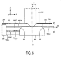
- Fig. 6 shows an embodiment of the interferometer system in which no extra interferometer unit is required.
- the measuring beam for the MAX,8 measuring axis is supplied by the interferometer unit 200 which also comprises the second Z detector.
- the measuring beam for the MAX,8 measuring axis traverses the space between the substrate and the projection lens and is reflected by a roof reflector 270 with two reflecting faces 271 and 272 to the Z measuring mirror 265.
- the mirror 265 reflects the measuring beam to the Z reflector 268 which, in its turn, reflects the measuring beam to the measuring mirror 265, whereafter this beam traverses the reverse path to the detector unit 200.
- the measuring beam is received by the afore-mentioned second detector.
- the Z measuring mirrors 260 and 265 extend in the Y direction, the direction perpendicular to the plane of the drawing of Figs. 5 and 6 throughout the length of the substrate holder. If the lithographic apparatus is a step-and-scanner, the Y direction is the scanning direction so that the Z measurement can be performed throughout the scanning length.
- the width of the Z measuring mirrors is equal to the diameter of the cross-section of the Z measuring beam at the area of this mirror, or is slightly larger if this beam traverses the path to the Z reflector twice. This means that this width can be limited and the surface of the Z measuring mirror can remain small. Due to their small total surface, the measuring mirrors can be manufactured in practice with the desired surface accuracy.
- f there is a given distance f between the principal axis AA' of the projection lens system PL and the end of the Z reflector 268.
- This distance is, for example of the order of 70 mm.
- the distance between the axis AA' and the measuring mirror should be at least equal to the distance f for that position. This may mean that, for the purpose of the Z measurement, the width of the substrate holder in the X direction should be increased by a given value.
- the width of the substrate holder should be increased by twice this value. Since the substrate holder should also have a given height in order that both the Z measuring mirror(s) and the X and Y measuring mirrors can be arranged on its side faces, a larger dimension in the X direction will considerably increase the weight of the holder. This is less desirable because of the required drive forces for the holder and stability requirements.
- a Z measuring mirror is therefore preferably arranged on a bar-shaped element having a beveled side face, which element is rigidly connected to the substrate holder.
- Fig. 7 shows an embodiment of the interferometer system in which the two Z measuring mirrors 293 and 294 are arranged on bar-shaped elements 291, 292.
- the required width for a measuring mirror is also equal to or slightly larger than the diameter of the cross-section of the measuring beam at the area of this mirror so that the dimension in the Z direction of the bar-shaped element can be limited
- the extra weight added to the substrate holder to render it suitable for performing the described Z measurement is thereby limited.
- the two Z measuring mirrors are arranged on the lower part of the substrate holder.
- the X measuring axes associated with the interferometer unit 200 can be positioned proximate to the upper face of the substrate holder so that the risk of Abbe errors for these measuring axes can be reduced. Moreover, a maximal portion of the side faces of the substrate holder and a maximal space between the projection system and the substrate holder are then available for performing measurements other than the measurements described and being irrelevant to the present invention.
- Fig. 7 also shows the projection beam PB.
- this beam has an oblong, for example rectangular, cross-section at the area of the substrate, whose longitudinal direction is parallel to the X direction.
- this beam is moved in the Y direction across the substrate by moving the mask and the substrate in the Y direction with respect to the projection beam and the projection lens system.
- EP patent application 97203771.7 describes various embodiments of a composite interferometer system with a Z measuring axis for an application other than for the implementation of the method in accordance with the present invention.
- These embodiments of the interferometer system with a plurality of X. and/or Y measuring axes may also be used for performing the method in accordance with the present invention.
- An interferometer system is preferred in which not only at least a Z measuring axis but also at least five other X and Y measuring axes are used because not only the X and Y position and the rotation about the Z axis but also the tilts of the substrate about the X axis and the Y axis can be measured therewith. It is not necessary to further describe the constructive details of the embodiments of the interferometer system.
- the path of a Z measuring beam which returns from the Z reflector and the Z measuring mirror may incorporate, between this Z measuring mirror and the interferometer with which this beam is associated, a retroreflector which reflects this measuring beam again to the Z measuring mirror and the Z reflector.
- a retroreflector which reflects this measuring beam again to the Z measuring mirror and the Z reflector.
- the interferometer system may be provided with an extra measuring axis, a reference measuring axis, which co-operates with a stationary reflector. The measuring beam of the reference axis traverses a constant geometrical path length.
- the optical path length which is the product of the geometrical path length and the refractive index of the traversed medium, is, however, influenced by a variation of the refractive index.
- This variation thus also influences the differences between the path lengths traversed by the reference axis measuring beam and the associated reference beam. This difference is measured by means of an extra, reference, detector in the interferometer unit with which the reference measuring axis is associated.
- the output signal of this detector can be used to correct the information obtained via other measuring axes for refractive index variations due to turbulences or variations of the ambient parameters.
- Refractive index variations may also be measured by means of two measuring beams which have considerably different wavelengths, for example, different by a factor of two, and traverse the same path within the medium in which the interferometer beams propagate. Since the refractive index for a beam is dependent on the wavelength of this beam, the optical path lengths for these beams are different despite the equal geometrical path lengths for the beams, so that these beams have a phase difference upon arrival at a detector. In the case of refractive index variations, there are also variations of this phase difference, so that a signal which is indicative of the refractive index variation is obtained.
- the components of the interferometer system(s), with the exception of the measuring mirrors, may be arranged in a rigid frame in which also the projection system is rigidly secured, which frame is suspended dynamically isolated from the other components of the apparatus.
- the interferometer components are now rigidly coupled free from disturbance to the projection system. Since said frame, also referred to as metrology frame, is suspended dynamically isolated or free from vibrations in the apparatus, the positions of the interferometer components present therein are no longer affected by external forces such as the drive forces for the substrate table and the mask table.
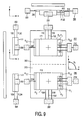
- Fig. 8 shows diagrammatically a step-and-scanning optical lithographic apparatus provided with a metrology frame.
- Such an apparatus not only comprises an interferometer system ISW for the substrate, but also an interferometer system ISM for measuring the X and Y displacements of the mask. Since these interferometer systems and the projection system PL are arranged in a metrology frame MF, these systems are rigidly fixed with respect to each other, and the image of the mask pattern formed by the projection system is coupled to the interferometer systems.
- the measuring mirrors 290 and 293 of the substrate interferometer system and the measuring mirror 297 of the mask interferometer system are part of the substrate holder WH and the mask holder MH, respectively, on which the substrate and the mask are rigidly fixed, the movements of the substrate and the mask are directly measured with these systems. Consequently, these movements and the mask pattern image formed are not affected by movements of other components of the apparatus, such as actuators for adjusting the mutual position of the substrate and the mask along the Z axis.
- the actuators for displacing the mask and the substrate in the X and Y directions form part of an actuator frame AF.
- the metrology frame is suspended in the actuator frame by means of diagrammatically shown dynamic isolators SU 1 , SU 2 , SU 3 and SU 4 so that this frame is dynamically decoupled from the rest of the apparatus.
- the mask table MT and the substrate table WT are arranged in the actuator frame.
- the substrate table has three Z actuators, two of which, ZA w,1 and ZA w,2 are shown, with which the Z position of the substrate can be adjusted by equal energization of the three actuators, or with which a tilt of the substrate can be realized by unequal energization of the three actuators. These movements can be realized also for the mask in an analogous manner if the mask table is also provided with three Z actuators, two of which, ZA r,1 and Z r,2 , are shown.
- the plate 263 which is rigidly secured to the lower part of the projection lens holder, is present in the metrology frame. As already described, the reflecting lower side 264 of this plate constitutes the Z reflector for the Z measuring axis of the interferometer system ISW.
- a lithographic apparatus of the stepping type in which a Z measurement is performed in accordance with the invention may also be used in a lithographic apparatus of the stepping type in which a Z measurement is performed in accordance with the invention.
- Such an apparatus does not comprise a mask interferometer system.
- the X and Y reference mirrors of the substrate interferometer system, and possibly of the mask interferometer system may be secured to the holder of the projection lens system so as to obtain the same advantages.
- a photolithographic projection apparatus provided with multi-axis interferometer systems, but without the Z measuring axis, in which the reference mirrors are secured to the holder of the projection lens system is known per se and described in PCT WO 97/33205 .
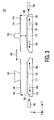
- Fig. 9 is a survey of the interferometer measurements which, in a given embodiment of a lithographic apparatus suitable for performing the method according to the invention, are performed in the projection station and the measuring station.
- This Figure shows the two substrate holders 111 and 113 with the X measuring mirrors R 1 , R' 1 , Y measuring mirrors R 2 and R' 2 and Z measuring mirrors R 3.1 , R 3.2 , R' 3.1 , R' 3.2 .
- the central part of Fig. 9 is a cross-section taken on the XY plane, the upper part is a cross-section taken on the XZ plane, and the left-hand part is a cross-section taken on the YZ plane.
- the reference numerals 300 and 310 denote the measuring area of the illumination station and that of the alignment station. Each measuring axis is indicated by two letters and one numeral. The first letter indicates the direction (X, Y or Z) in which the measurement is performed with the relevant measuring axis, the numeral shows the number of the measuring axis in this direction, and the second letter indicates whether the measurement takes place in the alignment station (M) or the illumination station (E). In the embodiment of Fig. 9, the measurements are performed along three measuring axes both in the X direction and in the Y direction, and two Z measurements are performed.
- the interferometer unit 330 is used for the Y measurements in the projection station.
- the corresponding interferometer units for the projection station and the measuring station are denoted by the same reference numerals, but the reference numerals for the interferometer units in the measuring station are primed.
- the two substrate tables may be secured to a common rotatable arm during this movement so that the substrates can be brought to the measuring station or the projection station via a common rotation.
- the substrate tables are preferably driven separately in such a way that they make rectilinear movements in the XY plane.
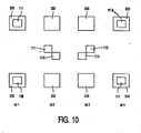
- Fig. 10 shows how the substrate holders 111 and 113 and the associated tables (not shown) move with respect to the projection station 300 and the measuring station 310 in that case. In this Figure, four different situations are denoted by SIT1, SIT2, SIT3 and SIT4 from left to right.
- the substrate holder 111 is present in the projection station 300 and the substrate present on this holder is illuminated, while the substrate holder 113 is present in the measuring station 310 and the substrate in this holder is measured.
- the illumination process and the measuring process have been completed, and the two substrate holders have left the relevant station.
- the two substrate holders have passed each other, and substrate holder 111 is on its way to the measuring station 310 and substrate holder 113 is on its way to the projection station 300.
- substrate holder 113 is positioned in the projection station 300 so that the substrate present on this holder can be illuminated, while the substrate holder 111, after removal of the first substrate and provided with a new substrate, is positioned in the measuring station 310 so that a measurement can be performed on this substrate.
- the method of measuring the height and position of substrate fields according to the present invention has been described with reference to a photolithographic apparatus for manufacturing IC structures. However, this method may also be used in photolithographic apparatuses for manufacturing other structures such as structures for integrated or planar optical systems, guidance and detection patterns of magnetic domain memories, or structures of liquid crystalline display panels. The method may also be used in other lithographic apparatuses in which radiation other than optical radiation such as ion radiation, electron radiation or X-ray radiation is used for imaging a mask pattern, either or not with reduction, on a substrate. The image may not only be an image formed by a projection system, but also a proximity image.
Abstract
Description
- The invention relates to a method of projecting a mask pattern on a plurality of fields of a substrate, provided with a radiation-sensitive layer, by means of a projection beam and a projection system, according to
claim 1. - The invention also relates to a lithographic projection apparatus according to claim 6 which is suitable for performing the method. This apparatus may be a stepper or a step-and-scanner.
- A method and apparatus of this type for manufacturing ICs is described in Japanese patent application
JP-A 61-196532 - The object of IP-A 61-196532 is to provide a method with which it can be ensured that the entire substrate field surface is within the depth of focus and with which it can be ascertained whether this surface has a quality which is too bad to be illuminated or should not be used at all. To realize this object,
JP-A 61-196532 - An important parameter of the current lithographic apparatuses is the throughput, i.e. the number of substrates which can be illuminated per unit of time by the apparatus, hence provided with images of the mask pattern. As is known, there is a very rapid development in the field of lithographic apparatuses. After the publication of
JP-A 61-196532 US 4,778,275 , but also an interferometer system is used with which the X and Y movements of the substrate and the positions of the substrate fields can be fixed in a system of co-ordinates. - An important breakthrough was the use of an interferometer system with at least five instead of three measuring axes. A lithographic apparatus provided with such an interferometer system is described in
EP-A 0 498 499 . With this interferometer system, not only the displacements of the substrate along the X axis and the Y axis and the rotation about the Z axis can be measured, but also the tilt about the X axis and the tilt about the Y axis can be measured very accurately. Consequently, each substrate field can be positioned with sufficient accuracy with respect to the mask pattern without separate alignments having to be performed per substrate field. The time required for illuminating the substrate can thus be reduced considerably. - In
JP-A 61-196532 JP-A 61-196532 - For the novel lithographic apparatuses and the lithographic apparatuses which are currently being developed, with which even smaller details must be imaged and an even greater positioning accuracy of the substrate fields is desirable, it is necessary to align per substrate field and to perform a focus and tilt correction despite the use of an interferometer system with five or more measuring axes.
- It has already been proposed, for example in
EP-A 0 687 957 and the English-language abstract ofJP-A 57-183031 - In the height-measuring station described in
JP-A 61-196532 - First, the height of the substrate field is measured at three different positions in this field by means of the three air sensors, so that the slope of this field can be computed. This slope is referred to as "temporary base plane". Subsequently, it is ensured by means of a vertical actuator which is present in the heighf-measuring station that the temporary base plane is parallel to a reference plane of the interferometer. Then, the air sensors of the substrate surface are moved to the reference plane of the substrate holder. Subsequently, the substrate field is measured with the interferometer, while the shape of the substrate field surface is computed from the interference pattern formed in the interferometer system. During this step the substrate must be moved vertically over small distances by the vertical actuator. Subsequently, the height of the substrate support reference plane is measured with the three air sensors. Finally, the correlation between this height and the temporary base plane is determined. The information thus obtained is sent to the projection station where it is used, after arrival of the relevant substrate, for adjusting the height of the substrate fields, at which only the height of the substrate reference plane is measured with three air sensors which are present in the projection station.
-
EP-A-0 793 073 discloses a lithographic projection apparatus system in which a height sensor is provided to measure the position of the surface of the substrate underneath the projection lens. The substrate is scanned under the lens to measure its surface before exposures are carried out. - It is an object of the present invention to provide a lithographic method and a lithographic apparatus which is based on a different concept and is simpler than that described in
JP-A 61-196532 - The method and apparatus according to the invention are defined in the appended claims.
- The axis of the projection beam is understood to mean the symmetry axis of the projection radiation. This radiation may consist of a single beam with a round cross-section or an annular cross-section or a cross-section in the form of a circular segment. The projection radiation may alternatively consist of, for example four sub-beams which are arranged in four quadrants and have for their object to increase the resolving power of the projection apparatus. The symmetry axis is then an axis through the center of the four quadrants. A projection beam with a cross-section in the form of a circular segment at the area of the mask plane is used in a step-and-scanner. In the latter case, the symmetry axis is an axis through the center of curvature of the circle.
- The invention is based on the recognition that the height and the profile of the substrate field can be measured in a considerably simpler way and within a shorter period of time as compared with the method described in
JP-A 61-196532 - The method according to the invention is preferably further characterized in that, for each substrate field, the height of this substrate field and the height of the substrate holder reference plane are measured simultaneously.
- This is made possible because two height sensors are used in the measuring station so that the measuring time is shorter.
- A preferred embodiment of the method is further characterized in that, both before and after introducing the substrate holder with the substrate into the projection station, and when measuring the height of the substrate holder reference plane, also the position of the substrate is measured along an X axis and an Y axis, the X axis and the Y axis being axes of a three-axis orthogonal system of co-ordinates, the Z axis of which is parallel to the axis of the projection beam.
- Due to the X and Y measurement, which can be performed with the above-mentioned interferometer system, the position of a substrate field is measured in a system of co-ordinates determined by the interferometer system, simultaneously with the height of this substrate field. The result of this measurement may be used in the projection station, inter alia, for identifying the substrate field. Moreover, the combination of the Z measurement with the X and Y measurements enhances the reliability and accuracy of these measurements.
- Since the X and Y positions of each substrate field are now determined both in the measuring station and in the projection station, a part of the alignment procedure required in lithography techniques can be performed before the substrate is introduced into the projection beam. An embodiment of the method for which this is the case is characterized in that, before introducing the substrate holder with the substrate into the projection station, a relation is determined for each substrate field between an alignment mark associated with said substrate field and at least one reference mark on the substrate holder, and, after introducing the substrate holder with the substrate into the projection station, each substrate field is aligned before it is illuminated, while using said relation and by aligning said reference mark with respect to a corresponding mark on the mask.
- During illumination of a first substrate, the most time-consuming part of the alignment procedure can thus be performed on a second substrate, so that also the time required for alignment can be considerably shorter. Advantage is taken of the fact that the X and Y position measurements required for the alignment are already performed for the purpose of the height measurements of the substrate fields. The principle and advantages of performing a part of the alignment procedure before a substrate is introduced into the projection beam are described in
EP-A-0 687 957 and in the English-language abstract ofJP-A 57-183031 - A particularly advantageous embodiment of the method according to the invention is characterized in that, in determining the surface profile of a plurality of substrate fields prior to introducing the substrate into the projection station, a certain route is followed as defined by the order in which successively inspected fields are disposed relative to one another, and that, when the substrate is subsequently introduced into the projection station and underneath the projection system, the same route is followed during illumination of the fields. This greatly simplifies the matching of data between the measurement positions (where the surface profile is determined) and exposure positions (where illumination occurs) of the fields on the substrate. Although such an embodiment follows the same routing at both the measurement and exposure stations, it should be explicitly noted that it is not restricted to following the same order, although this is certainly permitted.
- By using the method according to the invention, sharp images of the mask pattern in the substrate fields are obtained, so that the products, for example ICs, which are manufactured by means of the method have very well defined structures so that the invention is also embodied in these products.
- The invention also relates to a lithographic projection apparatus suitable for performing the method according to the invention. This apparatus, which comprises a projection station for projecting a mask pattern on a plurality of fields of a substrate arranged on a substrate holder, and a measuring station for measuring the height of each substrate field and the height of a reference plane of the substrate holder, wherein the path of the substrate through the apparatus extends via the measuring station to the projection station, is characterized in that the measuring station accommodates a first and a second height sensor for measuring the height of the substrate fields and the substrate holder reference plane, respectively, and the projection station accommodates a third height sensor for measuring the height of the substrate holder reference plane.
- This apparatus differs from the apparatus in accordance with
JP-A 61-196532 - In the novel apparatus, various types of height sensors can be used, such as capacitive or pneumatic meters. Moreover, the height sensors may be of mutually different types. Preferably, however, the three height sensors are optical height sensors.
- Optical height sensors are flexible in use, require few extra provisions in the apparatus and are very accurate and reliable.
- A preferred embodiment of the projection apparatus is characterized in that at least one of the second and third height sensors forms part of a separate composite XYZ interferometer system for measuring X and Y displacements and positions of the substrate, and has a number of X and Y measuring axes, which number is at least equal to the number of substrate displacements to be determined interferometrically, said measuring axes co-operating with X and Y measuring mirrors arranged on the substrate holder, said interferometer system further having a Z measuring axis which co-operates with a Z measuring mirror which is arranged on the substrate holder at an acute angle to the XY plane, said Z measuring axis and Z measuring mirror, together with a Z reflector and a Z detector, constituting the height sensor.
- A measuring axis of the interferometer system is understood to be an axis along which the position or the displacement in a given direction (X, Y or Z) of the substrate is measured. This measuring axis does not need to coincide with the chief ray of the measuring beam which is used for the relevant measurement. If the measuring beam is sent through the system twice and is reflected twice at substantially the same point by a measuring mirror, the measuring axis is situated between the chief ray of the measuring beam upon the first passage and the chief ray of this beam upon the second passage through the system.
- As regards stability and accuracy, an XY interferometer system extended with a Z measuring axis is eminently suitable for use as a height sensor in a lithographic apparatus. The height measurement can then be realized with relatively few and simple means: extra beam splitters and an extra Z detector in the interferometer system, and an extra measuring mirror on the substrate holder. Moreover, it is not necessary to reserve a space between the projection system and the substrate for providing a height sensor. The height of the substrate is now determined with respect to a Z reflector which is connected to the projection system.
- As already noted, it is of great advantage if also a part of the alignment procedure can take place in addition to a height measurement in the measuring station. An apparatus providing this facility is characterized in that the measuring station includes an optical alignment system which comprises elements for aligning alignment marks associated with the substrate fields, and at least one substrate holder alignment mark with respect to a reference mark within the measuring system.
- An alignment system for a measuring station which is only used for aligning a substrate on a substrate table is described in the above-mentioned
JP-A 57-183031 - A preferred embodiment of the apparatus is characterized in that the Z measuring mirror for the interferometer system is arranged on the substrate holder at an angle of substantially 45° to the XY plane.
- If the Z reflector is parallel to the XY plane, the Z measuring mirror may then have a minimal width because the Z measuring beam traverses the same path to and from the Z reflector.
- The apparatus may be further characterized in that the Z measuring mirror for the interferometer system is constituted by a beveled portion of an X or Y measuring mirror.
- A substrate holder side face which is suitable for this purpose is then divided into a straight portion and a beveled portion at an angle of preferably 45° to the straight portion, and both portions are reflective.
- A preferred embodiment of the apparatus is characterized in that the Z measuring mirror for the interferometer system is constituted by a beveled bar arranged on a side face of the substrate holder on which also an X or Y measuring mirror is arranged, said bar extending in the Z direction through only a small part of said side face and, in the direction perpendicular thereto, throughout the side face.
- Since the Z reflector is arranged against the holder of the projection system, there will be a given distance, for example of the order of 70 mm, between one end of this reflector and the axis of the projection system in a lithographic apparatus. In order that, also in an extreme X position of the substrate holder, the measuring beam reflected by the Z measuring mirror can reach the Z reflector, the distance between the axis of the projection system and the center of the Z measuring mirror must be minimally equal to said distance in this extreme position. This means that the substrate holder would have to be enlarged for the purpose of the Z measurement. Since this holder must have a given height, also because the X or Y measuring mirror must also be provided on the side face on which the Z measuring mirror is provided, an enlargement of the substrate holder for the purpose of the Z measuring mirror would considerably increase its weight. By providing the Z measuring mirror on a thin bar which is rigidly connected to the substrate holder, the weight of this holder can remain limited.
- In accordance with a further characteristic feature of the lithographic apparatus, the Z measuring mirror is preferably arranged on the part of the substrate holder remote from the substrate.
- By placing the Z measuring mirror on the lower side of the holder and the X or Y measuring mirror above it, the risk of dynamic Abbe errors in the X and Y directions can be reduced. Moreover, a maximal portion of the relevant side face of the substrate holder and a maximal space between the Z measuring mirror and the projection system are then suitable for other measurements.
- A separate reference mirror for the reference beam associated with the Z measuring beam may be arranged in the interferometer system. The Z detector which receives the Z measuring beam and the Z reference beam then supplies a signal in which the information about the Z position is mixed with information about the X position if the Z measuring mirror is arranged on the same side face of the substrate holder as the X measuring mirror, or with information about the Y position if the Z measuring mirror is arranged on the same side face as the Y measuring mirror. An electronic differentiation with the X position signal, or with the Y position signal, must then still be performed on this signal, i.e. this signal must be combined with the X position, or Y position, signal to obtain the pure Z position.
- Preferably, however, the apparatus is further characterized in that the reference mirror for the reference beam associated with the Z measuring beam is constituted by an X or Y measuring mirror which is arranged on that side face of the substrate holder on which also the Z measuring mirror is arranged.
- An optical differentiation is then performed, and the output signal of the Z detector comprises pure Z position information. It is not necessary to perform an electronic differentiation. The optical differentiation has the advantage that one is no longer dependent on the processing speed of the electronic circuits associated with the interferometer system.
- For the Z measuring axis, a beam splitter must combine the measuring beam and the associated reference beam, after they have been reflected by the measuring mirror and the reference mirror, respectively, such that the radiation spots formed by these beams in the plane of the Z detector coincide as satisfactorily as possible. The signal supplied by this detector then has a maximal amplitude. However, these radiation spots may be offset with respect to the detector due to an unwanted tilt of the measuring mirrors associated with these beams, so that the directions of these beams vary. This phenomenon is known as "beam walk-off'. Since the Z measuring beam is reflected by the Z measuring mirror as well as by the Z reflector, the beam walk-off for the Z measuring beam is larger than that for the Z reference beam. If use is made of the above-mentioned optical differentiation method, i.e. if the Z reference beam is sent to an X or Y measuring mirror, the beam walk-off can be reduced. In fact, the beam walk-off then varies in the same direction for both beams. The optical differentiation method thus provides a second advantage.
- To further reduce the beam walk-off, the apparatus is preferably further characterized in that the path of the Z measuring beam incorporates a retroreflector by which the Z measuring beam reflected by the measuring mirror and directed to the detector is reflected to said measuring mirror for further reflection on said mirror.
- Due to this extra reflection of the Z measuring beam on the measuring mirror, the original direction of the measuring beam is maintained, independent of a tilt of the mirrors which are present in the path of this beam.
- The number of X and Y measuring axes of the interferometer system may be different, dependent on the presence of other measuring systems in the apparatus. However, in addition to a Z measuring axis, the interferometer system preferably comprises at least five further measuring axes.
- In this system, the advantage of a maximal measuring accuracy is combined with that of an extra measuring facility, namely the Z measurement.
- To render the interferometric measurements independent of variations of the refractive index of the medium in which the measuring beams propagate, the interferometer system may be further characterized in that the system has a measuring axis along which two measuring beams of different wavelengths propagate.
- Since the same distance is measured with two beams of different wavelengths, and the refractive index of a medium is dependent on the wavelength of this measuring beam, a possible refractive index variation can be measured, and the measuring results of the interferometer system can be corrected therewith. Said measuring axis may be a separate reference measuring axis or one of the other measuring axes.
- The lithographic apparatus is preferably further characterized in that, with the exception of the measuring mirrors, the components of the projection station-interferometer system as well as the Z reflector are arranged in a rigid frame in which also a projection system is rigidly secured, which frame is suspended dynamically isolated from the other components of the apparatus.
- This measure considerably contributes to the realization of the desired measuring accuracy. The interferometer units are rigidly coupled free from disturbances to the projection system. Since said frame, also referred to as metrology frame, is suspended dynamically isolated, or free from vibrations, in the apparatus, the positions of the interferometer units present in this apparatus are no longer affected by external forces such as the drive forces for the substrate table of which the substrate holder forms part, and for the mask table of which the mask holder forms part.
- The apparatus may be further characterized in that the reference mirrors for the reference beams associated with the X and Y measuring beams are arranged on the holder of the projection system.
- The X and Y positions of the substrate are then no longer measured with respect to interferometer elements but with respect to the projection system. Possible deformations of the metrology frame then have a negligibly small influence on the position measurements.
- These and other aspects of the invention are apparent from and will be elucidated with reference to the embodiments described hereinafter.
- In the drawings:
- Fig. 1 shows an embodiment of a projection station of a lithographic projection apparatus;
- Fig. 2 shows the diagram of a lithographic projection apparatus with a separate height-measuring station and two substrate holders;
- Fig. 3 shows the height sensors used in the projection station and the measuring station;
- Fig. 4 shows an embodiment of a height sensor for measurements on a substrate;
- Figs. 5, 6 and 7 show a first, a second and a third embodiment of a height sensor for a substrate holder for use in both stations, which meter forms part of a composite interferometer system;
- Fig. 8 shows an embodiment of a projection station with a metrology frame;
- Fig. 9 is a survey of the interferometer measurements which are performed in the measuring station and in the projection station, and
- Fig. 10 illustrates the movements performed by the substrate holders in the apparatus of Fig. 2.
- Fig. 1 shows diagrammatically the optical elements of an embodiment of a photolithographic apparatus for repetitively imaging a mask pattern on a substrate. The main component of this apparatus is a projection column accommodating a projection lens system PL. A mask holder MH for a mask MA, in which the mask pattern C to be imaged is provided, is arranged above this system. The mask holder is present in a mask table MT. A substrate table WT is arranged below the projection lens system PL. This table accommodates a substrate holder WH for a substrate W which is provided with a photosensitive layer and on which the mask pattern must be imaged a number of times, each time in a different IC area Wd. The substrate table is movable in the X and Y directions so that, after imaging of the mask pattern on an IC area, a subsequent IC area can be positioned underneath the mask pattern.
- The apparatus further has an illumination system which comprises a radiation source LA, for example, a Krypton-Fluoride Excimer laser or a mercury lamp, a lens system LS a reflector RE and a condensor lens CO. The projection beam PB supplied by the illumination system illuminates the mask pattern C. This pattern is imaged by the projection lens system PL on an IC area of the substrate W. The illumination system may be alternatively implemented as described in
EP-A 0 658 810 . The projection lens system has a magnification of, for example, M = 1/4, a numerical aperture NA = 0.6 and a diffraction-limited image field having a diameter of 22 mm. - The apparatus further comprises a plurality of measuring systems, namely a system for aligning the mask MA with respect to the substrate W in the XY plane, an interferometer system for determining the X and Y positions and the orientation of the substrate holder and hence of the substrate, and a focus error detection system for determining a deviation between the focal or image plane of the projection lens system PL and the surface of the photosensitive layer on the substrate W. These measuring systems are parts of servosystems which comprise electronic signal-processing and control circuits and drivers, or actuators, with which the position and orientation of the substrate and the focusing can be corrected with reference to the signals supplied by the measuring systems.
- The alignment system uses two alignment marks M1 and M2 in the mask MA, indicated in the top right corner of Fig. 1. These marks preferably consist of diffraction gratings, but they may be alternatively formed by other marks, such as squares or strips which are optically different from their surroundings. The alignment marks are preferably two-dimensional, i.e. they extend in two mutually perpendicular directions, the X and Y directions in Fig. 1. The substrate W has at least two alignment marks, preferably also two-dimensional diffraction gratings, two of which, P1 and P2, are shown in Fig. 1. The marks P1 and P2 are located outside the area of the substrate W where the images of the pattern C must be formed. The grating marks P1 and P2 are preferably phase gratings and the grating marks M1 and M2 are preferably amplitude gratings.
- Fig. 1 shows a special embodiment of an alignment system, namely a double alignment system in which two alignment beams b and b' are used for aligning the substrate alignment mark P2 on the mask alignment mark M2, and the substrate alignment mark P1 on the mask alignment mark M1, respectively. The beam b is reflected by a reflecting
element 30, for example, a mirror to a reflectingsurface 27 of aprism 26. Thesurface 27 reflects the beam b to the substrate alignment mark P2 which passes a part of the radiation as beam b1 to the associated mask alignment mark M2 where an image of the mark P2 is formed. A reflectingelement 11, for example, a prism is arranged above the mark M2, which prism directs the radiation passed by the mark M2 towards a radiation-sensitive detector 13. The second alignment beam b' is reflected by amirror 31 to areflector 29 in the projection lens system PL. Thereflector 29 passes the beam b' to a second reflectingsurface 28 of theprism 26, which surface directs the beam b' onto the substrate alignment mark P1. This mark reflects a part of the radiation of the beam b' as beam b,' to the mask alignment mark M1 where an image of the mark P1 is formed. The radiation of the beam b1. passing through the mark M1 is directed towards a radiation-sensitive detector 13' by a reflector 11'. The operation of the double alignment system is described inUnited States patent 4,778,275 , to which reference is made for further details of this system. - The embodiment of the alignment system according to Fig. 1 is particularly suitable for an apparatus in which the projection lens system PL is designed for a projection beam PB having a short wavelength, for example, 248 nm, whereas the alignment beam has a considerably longer wavelength, for example, 633 nm. In fact, this system incorporates an extra lens, or correction lens, 25 in the projection column. This lens ensures that the substrate alignment marks are imaged in the plane of the mask alignment marks and with the correct magnification in spite of the fact that the projection lens system is not optimized for the wavelength of the alignment beam. The correction lens is arranged at such a height in the projection column that, on the one hand, the sub-beams of different diffraction orders of the alignment beam, which sub-beams are generated by a substrate alignment mark, are sufficiently separated in the plane of the correction lens so as to be able to influence these sub-beams separately, and, on the other hand, the correction lens has a negligible influence on the projection beam and the image formed therewith of the mask pattern C. The
correction lens 25 is preferably arranged in the Fourier plane of the projection lens system. If the correction lens is arranged in a plane in which the chief rays of the alignment beams b and b1. intersect each other, as is shown in Fig. 1, this lens can be used for correcting the two alignment beams. For further details about the object and operation of thecorrection lens 25, reference is made toUS patent 5,100,237 . - A wedge or another deflection element, such as a diffraction element, is preferably arranged in the proximity of an alignment mark further down the path of the alignment-beam(s). With such a deflection element (not shown in Fig. 1), alignment errors may be prevented, which result from unintentional phase differences within the selected alignment beam portions captured by the
detector 13 or 13', which phase differences may occur if the symmetry axis of the alignment beam portions coming from a substrate alignment mark is not perpendicular to the mask plate, so that false reflections may occur within this plate. An alignment system provided with such a deflection element is described inUS patent 5,481,362 . - In addition to the global alignment marks P1 and P2 shown in Fig. 1, which marks are used for aligning the total substrate with respect to the mask, referred to as global alignment, the substrate may be provided with further alignment marks, for example one mark per IC area, so as to align the relevant area with respect to the mask pattern for each IC area. The mask may have more than two alignment marks, while the further alignment marks may be used, for example, to measure the rotation of the mask about the Z axis so as to correct therefor.
- For accurately determining the X and Y positions of the substrate table WT, known projection apparatuses comprise a multi-axis interferometer system.
US patent 4,251,160 describes a two-axis system andUS patent 4,737,283 describes a three-axis system. In Fig. 1, such an interferometer system is diagrammatically represented by theelements radiation source 50, for example a laser, is split into a measuring beam b4.m and a reference beam b4,r by abeam splitter 51. The measuring beam reaches a reflecting side face 54 of the substrate holder WH and the measuring beam reflected by this side face is combined by the beam splitter with the reference beam reflected by astationary reflector 52, for example, a "comer cube" reflector. The intensity of the combined beam can be measured with adetector 53 and the displacement, in this case in the X direction, of the substrate holder WH can be derived from the output signal of this detector, and also an instantaneous position of this holder can be established. - As is diagrammatically shown in Fig. 1, the interferometer signals, represented by one signal S53 for the sake of simplicity, and the signals S13 and S13' of the alignment system are applied to a signal-processing unit SPU, for example a microcomputer, which processes said signals to control signals SAC for an actuator AC with which the substrate holder is moved in the XY plane via the substrate table WT.
- With an interferometer system, which does not only comprise the X measuring axis shown in Fig. 1 but also a Y measuring axis and possibly a third measuring axis, the positions of, and the mutual distances between, the alignment marks P1, P2 and M1, M2 in a system of co-ordinates defined by the stationary interferometer system can be laid down during the initial, or global, alignment of the mask with respect to the substrate. This interferometer system is also used to enable the substrate table to step very accurately, i.e. to move it through predetermined distances and directions. Such a step is performed to position a subsequent IC field under the mask pattern and the projection lens system after the mask pattern has been imaged with one (or more) flash(es) in a first IC area or field, so that the mask pattern can also be imaged in this field. These step and imaging operations continue until all IC fields have been provided with a mask pattern image. A lithographic apparatus operating in this manner is referred to as stepper.
- Due to the demand for more electronic components per surface unit of an IC field, on the one hand, and larger IC fields, on the other hand, increasingly stricter requirements are imposed on the resolving power and the image field of the projection lens system. To alleviate these technologically contradictory requirements, it has already been proposed to use a step-and-scanner. In such an apparatus, the same stepping movements as in a stepper are performed, but only a small portion of the mask pattern is imaged on a corresponding sub-field of the IC field when imaging the mask pattern on an IC field. By imaging successive parts of the mask pattern on successive sub-fields of the IC area, an image of the entire mask pattern on an IC field is obtained. To this end, the mask pattern is illuminated with a projection beam which forms a small, for example rectangular or arcuate, illumination spot at the location of the mask pattern, and the substrate table is moved in a given direction, the scan direction, with respect to the projection lens system and the projection beam, and the mask table is moved in the same or the opposite direction, while the rate of the substrate table is M times that of the mask table. M is the magnification with which the mask pattern is imaged. It should be ensured that the mask and the substrate have the correct mutual position at any moment, which can be realized by means of a very accurate synchronization of the movements of the mask and the substrate, i.e. the rate Vsub of the substrate is always equal to M times the rate VMA of the mask.
- To check the condition VSub = M.VMA, the step-and-scanner should not only comprise a substrate interferometer system but also a mask interferometer system with which the movement and the position of the mask can be measured accurately. The measuring mirror of the last-mentioned system is preferably secured to the mask holder. The mask interferometer system is denoted in Fig. 1 by the
elements elements - To ascertain whether these conditions are fulfilled, it is sufficient that both the interferometer system for the substrate and that for the mask have three measuring axes. However, the substrate interferometer system preferably has five measuring axes. As described in
EP-A 0 498 499 , not only X, Y and ϕz,w but also ϕx,w and ϕy,w, i.e. the tilts of the substrate about the X axis and the Y axis can be measured. For the different embodiments of the interferometer units of which a five-axis interferometer system may be composed, reference is made toEP-A 0 498 499 . To be able to measure the tilts about the X axis and the Y axis also for the mask, a five-axis mask interferometer system may be used. However, it is alternatively possible to combine a three-axis mask interferometer system with other sensors, such as capacitive sensors, for measuring the tilts of the mask about the X axis and the Y axis. - Before a substrate can be illuminated in the projection station, the height in the Z direction of the substrate must first be measured with respect to the projection system and possibly adapted so that the mask pattern can always be imaged sharply on the substrate. In known projection apparatuses, an optical focus error detection device is used for this height measurement, which device is present in the projection station and is secured to the projection system. This detection device is described in
US-A 4,356,392 . - Moreover, the local tilt of the substrate must be measured. For this purpose, a focus-and-level device which is present in the projection station is used in known apparatuses. Such a device is described in
US-A 5,191,200 . The focus-and-level device is rigidly coupled to the projection system because the elements of this device are arranged in a plate which forms part of a measuring frame in which also the projection system is rigidly secured. A coupling is thereby established between the image plane of the projection system and the surface of the substrate holder. - A given space is required for using the focus-and-level device so that the projection system should have such a design that it has a given free working distance, the distance between the last element of this system and the substrate surface. Moreover, problems may occur during measurements with the aid of the focus-and-level device when measuring the so-called edge-dies, i.e. substrate fields located at the edge of the substrate. The measurements on the separate substrate fields require a certain amount of time during which the projection station cannot be used for the actual illumination of the substrate.
- These problems can be avoided if the Z positions and the tilts of the substrate fields are measured in a different manner, and if this measurement is largely performed outside the projection station. In analogy with what has already been proposed for aligning the substrate fields with respect to the mask pattern, the projection apparatus may to this end be extended with a Z measuring station and with a second, or more, substrate holder(s).
- Fig. 2 shows diagrammatically the mechanical elements of such an extended photolithographic projection apparatus with two substrate holders and a Z measuring station. This apparatus comprises a
frame 101 which, viewed in a vertical Z direction, successively comprises apositioning device 103, amask holder 107 and anillumination unit 108 provided with aradiation source 109. Thepositioning device 103 comprises afirst substrate holder 111 and a second,identical substrate holder 113. Aprojection lens holder 105 is present between the mask holder and the substrate holder. Thesubstrate holders face first substrate 120 and asecond substrate 121, respectively, may be arranged. The first andsecond substrate holders frame 101 in a first direction, parallel to an X direction which is perpendicular to the Z direction, and in a second direction parallel to an Y direction which is perpendicular to the Z direction and the X direction, by means of afirst displacement unit 123 and asecond displacement unit 125, respectively, of thepositioning device 103. Themask holder 107 has a supportingsurface 127 which extends perpendicularly to the Z direction and on which a mask 129 can be arranged. - The substrates which must be illuminated are arranged in a magazine which is entered into the apparatus. From this magazine, the substrates are consecutively introduced into the apparatus by means of a transport mechanism. Said magazine and transport mechanism, which are not shown in Fig. 2, are known per se. The Z measuring station is diagrammatically represented in Fig. 2 by a measuring
unit 133 which is also secured to theframe 101. In the situation of the apparatus shown in Fig. 2, thefirst substrate holder 111 is present in the projection station and thefirst substrate 120 is illuminated via the mask 129 with radiation emitted by theillumination unit 108 and focused by the projection system which is present in theholder 105. Only theoptical axis 131 of this projection system is shown. The second substrate holder is present in the measuring station. As will be described hereinafter, the height and the position of the substrate fields are determined in this station and related to the height of a reference plane on thesecond substrate holder 113. After the illumination of thesubstrate 119 is finished, thefirst substrate holder 111 is displaced by the positioning device from the projection station to the measuring station. From this station, thefirst substrate 120 is moved by said transport mechanism to said magazine. Simultaneously, the second substrate holder is moved from the measuring station to the projection station by thepositioning device 103. Since the ideal height and position of the substrate fields in the measuring station is already related to the height of the substrate holder reference plane, only the height of the substrate holder reference plane is to be measured and, if necessary, corrected in the projection station. This measurement and correction is a relatively simple process which can be performed quickly. Since the more difficult and more time-consuming measurement of the height and position of the substrate fields is performed in the measuring station and time-parallel with the illumination of the substrate which is present in the projection station at that instant, the projection station can be used for the illumination itself for a maximum period of time so that a large number of substrates can be illuminated per unit of time. - The principle and advantages of a photolithographic apparatus with two substrate holders and tables are described in, inter alia,
EP-A 0 687 957 and in the English-language abstract ofJP-A 57-183031 - Fig. 3 shows diagrammatically the method according to the invention for measuring the height and the position of the substrate fields. In this Figure, the elements which correspond to those of Fig. 2 are denoted by the same reference numerals. The righthand part of the Figure shows the measuring
station 133 accommodating thesecond substrate holder 113 with thesecond substrate 121 at the instant indicated in the Figure. The left-hand part of the Figure shows a small part of the projection station accommodating thefirst substrate holder 111 with thefirst substrate 120. Thearrow 140 illustrates how the substrates are moved in the projection apparatus. The measuringstation 133 comprises afirst height sensor 150 shown only diagrammatically, which may be implemented in various known manners. This height sensor may be, for example a capacitive, pneumatic or optical height sensor. An example of an optical height sensor is shown in Fig. 4. - In this Figure,
element 190 is a radiation source, for example a diode laser which supplies a measuring beam b3. This beam passes abeam splitter 191 and is reflected by a reflectingprism 192 to the surface of thesubstrate 121, the beam being incident on the substrate at a very small angle α. The beam reflected by the substrate surface is reflected by aprism 193 to aretroreflector 194. The retroreflector reflects the beam in itself so that this beam once more traverses the same path as beam b'3, via reflections on theprism 193, the substrate surface and theprism 192. Thebeam splitter 195 and a reflecting prism reflect the measuring beam to a radiation-sensitive detection system 196. This system consists of, for example a position-sensitive detector or of two separate detectors. The position of the radiation spot formed by the beam b'3 on this system is dependent on the height of the portion of the substrate surface on which the measuring beam is incident. For an extensive description of this optical height sensor, reference is made toUS-A 4,356,392 in which such a height sensor is referred to as focus error detection device. - A height sensor which is particularly suitable for measurements on a substrate provided with a photosensitive layer is of the type which also operates with a measuring beam which is obliquely incident on the photosensitive layer but in which this beam has a broad wavelength band. Due to the broadband character of the measuring beam, interferences which may occur in the beam due to multiple reflections on the layers of the assembly of substrate and photosensitive layer will average each other out and will not affect the height-measuring signal. To obtain a sufficiently accurate measuring signal, the path of the measuring beam incorporates a first grating between the radiation source and the substrate, and a second grating between this substrate and the detection system. The first grating is imaged on the second grating via a reflection on the radiation-sensitive layer, and the extent to which the image of the first grating coincides with the second grating is determined by the height of the radiation-sensitive layer. For an extensive description of this height sensor, reference is made to
US-A 5,191,200 in which different embodiments of this height sensor, which is referred to as focus detection system in this patent, are described. - The
height sensor 150 measures only a small area of thesubstrate 121 at any instant. During the height measurement, thesubstrate holder 113 with thesubstrate 121 is moved under the height sensor in the Z and Y directions as is illustrated by means of thearrows second height sensor 160, which is also shown only diagrammatically, measuring the height of areference plane 170 of the substrate holder. This measurement is performed simultaneously with, and as many times as, the height measurement of the substrate. Then, the measured values of the two height sensors can be related to each other, and the height of thereference plane 170 associated with the ideal height and position of the relevant substrate field can be computed for each substrate field. Various embodiments of the second height sensor are also possible. As will hereinafter be explained, this height sensor is preferably implemented as an interferometer and the reference plane is a beveled reflecting face of the substrate holder, which face functions as Z measuring mirror for the interferometer. This face reflects aninterferometer measuring beam 165 to aZ reflector 175 which is arranged on aplate 174 coupled to theheight sensor 150. The Z reflector reflects the measuring beam to the interferometer again and forms the reference with respect to which the height of the substrate holder is measured. - During the height measurement on the
substrate 121 and thesubstrate holder 113, thesubstrate 120 is illuminated in the projection station. After this height measurement and illumination have been performed, thesubstrate holder 111 is removed from the projection station, thesubstrate 120 is removed from this holder and the holder is provided with a new substrate and then placed in the measuringstation 150 where it is measured. Meanwhile, thesubstrate holder 113 and the substrate have been removed from this station and placed in the projection station. In this station, the substrate holder is moved in the X and Y directions under theprojection system 305, as is indicated by thearrows holder reference plane 172 is at the height computed in the measuringstation 150 and associated with the ideal height of the relevant substrate field. To this end, the projection station is provided with athird height sensor 180. The signal from this height sensor can be used to correct the height of the supporting surface of the substrate holder and hence the height and the position of the relevant substrate field. To this end, for example this signal can be applied to a Z actuator which is present in the substrate holder. - In principle, also the
height sensor 180 can be implemented in various ways. However, this height sensor is preferably also a Z interferometer. Themeasuring beam 185 of this interferometer is reflected by the substratesupport reference plane 172 functioning as the Z measuring mirror to aZ reflector 186 which reflects the beam via theZ measuring mirror 172 back to the interferometer. TheZ reflector 186 is arranged on aplate 184 which is secured to theprojection system 305. - An advantage of the use of a Z interferometer as a height meter for the substrate holder is that this meter can be integrated in the X and Y interferometer system which is already present in the projection station for measuring the X and Y positions of the substrate and the substrate fields. Using only a few extra elements, such as a splitting mirror and a Z detector, it can be ensured that a known interferometer system, such as the system described in
EP-A 0 498 499 , not only supplies and is able to process X and Y measuring beams but also at least a Z measuring beam. - Simultaneously with the measurement of the height of the substrate and the separate substrate fields, it is also possible to measure the position of the substrate and the substrate field position required for performing the Z measurement according to the invention, the height of which field is measured at that instant, by using a composite XYZ interferometer system also in the Z measuring station. In the projection station, the composite interferometer system may be used to ensure that a substrate field which is about to be illuminated is brought underneath the projection system and positioned at the correct height. The XY measurement, on the one hand, and the Z measurement, on the other hand, performed by a composite interferometer system has also an important synergetic effect. On the one hand, the height, or Z position of the substrate and the substrate fields must be known so as to be able to measure the X and Y positions of this substrate and the substrate fields with great accuracy and, on the other hand, the X and Y positions of the substrate and the substrate fields must be known so as to be able to measure the Z position of this substrate and the substrate fields with great accuracy. Since the composite interferometer supplies information about the X and Y position as well as the Z position, it is thus possible to perform an optimal and rapid measurement.
- A further considerable advantage of the use of a composite interferometer system in the measuring station as well as the projection station is that a part of the procedure for aligning the substrate and the substrate fields in the X and Y directions can also take place in the measuring station. For aligning the substrate with respect to the mask pattern, this substrate and the mask are usually provided with alignment marks, and for aligning the separate substrate fields, each substrate field is provided with a separate alignment mark. The extent of alignment is determined by imaging a substrate alignment mark and a mask alignment mark on each other and by detecting whether an alignment mark coincides correctly with the image of the other alignment mark. A position-measuring system, preferably an interferometer system, must be used for measuring the displacements of the substrate and for fixing the positions of the substrate fields in a system of co-ordinates. By providing also the substrate holder with one or more alignment marks and by aligning the substrate alignment marks and the substrate holder alignment marks in the measuring station with respect to a reference alignment mark present in the measuring station, a relation can be established between each substrate alignment mark and the substrate holder alignment mark. It is then only necessary to align the substrate holder alignment mark with respect to the mask alignment mark in the projection system. This is a fairly simple process requiring a short time, whereas the alignment of the marks of the substrate fields is more time-consuming. Since the latter process takes place in the measuring station and time-parallel with the illumination of another substrate, considerable time can be saved, also as regards the alignment.
- As already noted, the XYZ interferometer system used for performing the novel method may, in principle, be constructed as described in
EP-A 0 498 499 , on the condition that the system described therein is extended with at least one Z measuring axis whose measuring beam is directed onto the Z measuring mirror. - As is known, an interferometer not only comprises a measuring beam which is directed onto and reflected by the measuring mirror which is secured to the object on which the measurement must be performed, but also a reference beam which is directed onto and reflected by a stationary reference mirror. For the composite XYZ interferometer system, the X and Y reference mirrors may be arranged in the interferometer units constituting the interferometer system as described in
EP-A 0 498 499 . Also the reference mirror for a Z measuring beam may be arranged in such a unit However, the Z reference mirror is preferably formed by an X or Y measuring mirror, as illustrated in Fig. 5. - In this Figure, which relates to the substrate interferometer system of the projection station, the Z reference beam is denoted by bz,lr. This beam comes from an
interferometer unit 200 which, in addition to two X measuring axes, one of which is not shown and the other being MAX,2, also comprises a Z measuring axis MAX,7, which measuring axis is located as close as possible to the upper face of a substrate holder WH. TheZ measuring mirror 260 reflects the Z measuring beam of the measuring axis MAX,7 to aZ reflector 264 which is arranged on aplate 263 which is rigidly secured to the holder LH of the projection system and may form part of a larger metrology frame. The Z reflector reflects the Z measuring beam to theZ measuring mirror 260 which, in its turn, reflects the measuring beam to theinterferometer unit 200. This unit accommodates a separate detector for the Z measuring beam. Together with other signals, the output signal of this detector can be processed to a Z measuring signal. - The
Z measuring mirror 260 in Fig. 5 is arranged at an angle of 45° to the XY plane, the plane in which the X and Y. measuring beams propagate. In principle, the Z measuring mirror may also extend at a different acute angle to the XY plane. However, the angle of 45° is preferred because the Z measuring beam traverses the same path to and from theZ reflector 264 and the Z measuring minor may then have a minimal width. - In this embodiment of the interferometer system, in which the Z measuring beam impinges upon the Z measuring minor at a position which is proximate to the upper face of the substrate holder, and hence proximate to the substrate, possible tilts of the substrate have a negligible influence on the Z measuring signal
- The X measuring minor is used as a reference minor for the Z measurement, as is shown in Fig. 5. The reference beam bz,1r reflected by this mirror then does not only comprise Z position information but also X position information so that the combination on the Z detector of this reference beam with the Z measuring beam results in the output signal of this detector being a pure Z position signal Thus, an optical differentiation is performed. Instead of using the
X measuring mirror 261 as a reference mirror for the Z measurement, it is also possible to arrange a reference minor for the Z measurement in theinterferometer unit 200. The signal which is then supplied by the Z detector does not contain pure Z position information, but the Z position information in that signal is mixed with X position information. For obtaining a pure Z position signal, the X position information must be removed from the detector signal, hence subtracted from this signal. In other words, an electronic differentiation must be used. Particularly if the substrate holder must be moved at great speeds and accelerations, which is desirable in lithographic apparatuses, the rate at which the electronic circuits associated with the interferometer system can process the measuring signals may be a restrictive factor. There is no such restriction when an optical differentiation is used. The optical differentiation, i.e. the use of an X or Y measuring mirror as a reference mirror for the Z measurement, can be used in all embodiments of the XYZ interferometer system. - As is also illustrated in Fig. 5, the interferometer system may be implemented in such a way that two Z measurements can be performed therewith.
- To this end, the
side face 265 of the substrate holder WH opposite the firstZ measuring mirror 260 is also beveled and provided with a second Z measuring mirror. This mirror co-operates with a second Z measuring beam which extends along the Z measuring axis MAX,8. The second Z measuring beam is reflected by the measuring mirror to asecond Z reflector 268 which is arranged on the lower side of theplate 263. The second Z measuring beam is reflected by theZ reflector 268 to the measuring mirror which, in its turn, reflects the measuring beam to a detector associated with the measuring axis MAX, 8. By adding the signals supplied by the measuring axes MAX,7 and MAX,8, the average Z position of the substrate can be determined. The value for the Z position thus obtained is independent of the X position of the substrate holder. - With the embodiment shown in Fig. 5, a signal which is indicative of a tilt of the substrate about the Y axis can also be obtained. This signal is proportional to the difference of the signals supplied by the MAX,7 and MAX,8 measuring axes.
- In the embodiment of Fig. 5, a
separate interferometer unit 280 is required which is provided with an extra radiation source and accommodates the second Z detector. Fig. 6 shows an embodiment of the interferometer system in which no extra interferometer unit is required. In this embodiment, the measuring beam for the MAX,8 measuring axis is supplied by theinterferometer unit 200 which also comprises the second Z detector. The measuring beam for the MAX,8 measuring axis traverses the space between the substrate and the projection lens and is reflected by aroof reflector 270 with two reflectingfaces Z measuring mirror 265. Themirror 265 reflects the measuring beam to theZ reflector 268 which, in its turn, reflects the measuring beam to the measuringmirror 265, whereafter this beam traverses the reverse path to thedetector unit 200. In this unit, the measuring beam is received by the afore-mentioned second detector. - The Z measuring mirrors 260 and 265 extend in the Y direction, the direction perpendicular to the plane of the drawing of Figs. 5 and 6 throughout the length of the substrate holder. If the lithographic apparatus is a step-and-scanner, the Y direction is the scanning direction so that the Z measurement can be performed throughout the scanning length.
- In principle, the width of the Z measuring mirrors is equal to the diameter of the cross-section of the Z measuring beam at the area of this mirror, or is slightly larger if this beam traverses the path to the Z reflector twice. This means that this width can be limited and the surface of the Z measuring mirror can remain small. Due to their small total surface, the measuring mirrors can be manufactured in practice with the desired surface accuracy.
- As is shown in Fig. 6, there is a given distance f between the principal axis AA' of the projection lens system PL and the end of the
Z reflector 268. This distance is, for example of the order of 70 mm. In order that a Z measurement can also be performed in an extreme X position of the substrate holder WH, in which the extreme right portion of the substrate is illuminated, as is indicated in Fig. 7, in figure 6 the distance between the axis AA' and the measuring mirror should be at least equal to the distance f for that position. This may mean that, for the purpose of the Z measurement, the width of the substrate holder in the X direction should be increased by a given value. If, in addition to a Z measurement via the MAX,8 measuring axis, also a Z measurement via the MAY,7 measuring axis is performed, the width of the substrate holder should be increased by twice this value. Since the substrate holder should also have a given height in order that both the Z measuring mirror(s) and the X and Y measuring mirrors can be arranged on its side faces, a larger dimension in the X direction will considerably increase the weight of the holder. This is less desirable because of the required drive forces for the holder and stability requirements. A Z measuring mirror is therefore preferably arranged on a bar-shaped element having a beveled side face, which element is rigidly connected to the substrate holder. - Fig. 7 shows an embodiment of the interferometer system in which the two Z measuring mirrors 293 and 294 are arranged on bar-shaped
elements interferometer unit 200 can be positioned proximate to the upper face of the substrate holder so that the risk of Abbe errors for these measuring axes can be reduced. Moreover, a maximal portion of the side faces of the substrate holder and a maximal space between the projection system and the substrate holder are then available for performing measurements other than the measurements described and being irrelevant to the present invention. - Fig. 7 also shows the projection beam PB. In the case of a step-and-scanning lithographic apparatus, this beam has an oblong, for example rectangular, cross-section at the area of the substrate, whose longitudinal direction is parallel to the X direction. Upon each image of the mask pattern on a substrate field, this beam is moved in the Y direction across the substrate by moving the mask and the substrate in the Y direction with respect to the projection beam and the projection lens system.
-
EP patent application 97203771.7 WO 99/28790 - The path of a Z measuring beam which returns from the Z reflector and the Z measuring mirror may incorporate, between this Z measuring mirror and the interferometer with which this beam is associated, a retroreflector which reflects this measuring beam again to the Z measuring mirror and the Z reflector. As a result, extra reflections of the measuring beam occur on the Z measuring mirror and the Z reflector so that it is achieved that the original direction of the measuring beam is maintained when possible tilts of the mirrors which are present in the path of this measuring beam occur. Thus, the influence of a beam walk-off on the Z measuring signal can be reduced considerably. An embodiment of the interferometer system with a retroreflector in the path of the Z measuring beam is also described in the above-mentioned prior patent application.
- In view of the required accuracy of the composite interferometer system for a lithographic apparatus, changes of ambient parameters, such as temperature, air pressure, humidity may start playing a role. These changes cause a variation of the refractive index of the medium in which the interferometer beams propagate. Such a variation may also be caused by turbulences in the medium. To be able to determine these variations, so that they can be corrected, the interferometer system may be provided with an extra measuring axis, a reference measuring axis, which co-operates with a stationary reflector. The measuring beam of the reference axis traverses a constant geometrical path length. The optical path length, which is the product of the geometrical path length and the refractive index of the traversed medium, is, however, influenced by a variation of the refractive index. This variation thus also influences the differences between the path lengths traversed by the reference axis measuring beam and the associated reference beam. This difference is measured by means of an extra, reference, detector in the interferometer unit with which the reference measuring axis is associated. The output signal of this detector can be used to correct the information obtained via other measuring axes for refractive index variations due to turbulences or variations of the ambient parameters.
- Refractive index variations may also be measured by means of two measuring beams which have considerably different wavelengths, for example, different by a factor of two, and traverse the same path within the medium in which the interferometer beams propagate. Since the refractive index for a beam is dependent on the wavelength of this beam, the optical path lengths for these beams are different despite the equal geometrical path lengths for the beams, so that these beams have a phase difference upon arrival at a detector. In the case of refractive index variations, there are also variations of this phase difference, so that a signal which is indicative of the refractive index variation is obtained.
- To ensure that the mask and the substrate are positioned with respect to each other in an extremely accurate manner in a lithographic apparatus having a high feed-through rate for the substrates during illumination of the IC areas, it should be prevented that forces of the actuators for the substrate holder and the mask holder are transferred to components of the interferometer system for the substrate holder and, in the case of a step-and-scanner, to the interferometer system for the mask holder. To this end, the components of the interferometer system(s), with the exception of the measuring mirrors, may be arranged in a rigid frame in which also the projection system is rigidly secured, which frame is suspended dynamically isolated from the other components of the apparatus. The interferometer components are now rigidly coupled free from disturbance to the projection system. Since said frame, also referred to as metrology frame, is suspended dynamically isolated or free from vibrations in the apparatus, the positions of the interferometer components present therein are no longer affected by external forces such as the drive forces for the substrate table and the mask table.
- Fig. 8 shows diagrammatically a step-and-scanning optical lithographic apparatus provided with a metrology frame. Such an apparatus not only comprises an interferometer system ISW for the substrate, but also an interferometer system ISM for measuring the X and Y displacements of the mask. Since these interferometer systems and the projection system PL are arranged in a metrology frame MF, these systems are rigidly fixed with respect to each other, and the image of the mask pattern formed by the projection system is coupled to the interferometer systems.
- Since the measuring mirrors 290 and 293 of the substrate interferometer system and the measuring
mirror 297 of the mask interferometer system are part of the substrate holder WH and the mask holder MH, respectively, on which the substrate and the mask are rigidly fixed, the movements of the substrate and the mask are directly measured with these systems. Consequently, these movements and the mask pattern image formed are not affected by movements of other components of the apparatus, such as actuators for adjusting the mutual position of the substrate and the mask along the Z axis. - The actuators for displacing the mask and the substrate in the X and Y directions, of which only the X actuators XAw and XAr are illustrated by way of rods in Fig. 8, form part of an actuator frame AF.
- The metrology frame is suspended in the actuator frame by means of diagrammatically shown dynamic isolators SU1, SU2, SU3 and SU4 so that this frame is dynamically decoupled from the rest of the apparatus. The mask table MT and the substrate table WT are arranged in the actuator frame. The substrate table has three Z actuators, two of which, ZAw,1 and ZAw,2 are shown, with which the Z position of the substrate can be adjusted by equal energization of the three actuators, or with which a tilt of the substrate can be realized by unequal energization of the three actuators. These movements can be realized also for the mask in an analogous manner if the mask table is also provided with three Z actuators, two of which, ZAr,1 and Zr,2, are shown.
- The
plate 263, which is rigidly secured to the lower part of the projection lens holder, is present in the metrology frame. As already described, the reflectinglower side 264 of this plate constitutes the Z reflector for the Z measuring axis of the interferometer system ISW. - The construction shown in Fig. 8 with a metrology frame and an actuator frame may also be used in a lithographic apparatus of the stepping type in which a Z measurement is performed in accordance with the invention. Such an apparatus does not comprise a mask interferometer system.
- Strict requirements with respect to rigidity and stability must be imposed on the metrology frame, and the material of this frame must have a very small temperature coefficient of expansion. However, these requirements may be alleviated if the reference mirrors for the X and Y measuring axes of the substrate interferometer system and possibly of the mask interferometer system are secured to the holder of the projection lens system PL or on the
metrology plate 263. The interferometer systems and the projection lens system are then optically coupled and mutual movements can no longer affect the measurements. This facility is diagrammatically shown in Fig. 8 with the two reference mirrors 298 and 299 under theplate 263. The reference beams may be guided from the substrate interferometer system to these reference mirror via reflectors (not shown). Also for the mask interferometer system, the reference mirrors may be secured to the holder of the projection lens system. - It is to be noted explicitly that, also in a lithographic projection apparatus without a metrology frame, the X and Y reference mirrors of the substrate interferometer system, and possibly of the mask interferometer system, may be secured to the holder of the projection lens system so as to obtain the same advantages. A photolithographic projection apparatus provided with multi-axis interferometer systems, but without the Z measuring axis, in which the reference mirrors are secured to the holder of the projection lens system is known per se and described in PCT
WO 97/33205 - Fig. 9 is a survey of the interferometer measurements which, in a given embodiment of a lithographic apparatus suitable for performing the method according to the invention, are performed in the projection station and the measuring station. This Figure shows the two
substrate holders reference numerals interferometer unit 330 is used for the Y measurements in the projection station. The corresponding interferometer units for the projection station and the measuring station are denoted by the same reference numerals, but the reference numerals for the interferometer units in the measuring station are primed. - In order that the two substrate tables and associated holders are moved from the measuring station to the projection station, and vice versa, in a lithographic apparatus, the two substrate tables may be secured to a common rotatable arm during this movement so that the substrates can be brought to the measuring station or the projection station via a common rotation. However, for performing these movements from and to the stations, the substrate tables are preferably driven separately in such a way that they make rectilinear movements in the XY plane. Fig. 10 shows how the
substrate holders projection station 300 and the measuringstation 310 in that case. In this Figure, four different situations are denoted by SIT1, SIT2, SIT3 and SIT4 from left to right. In SIT1, thesubstrate holder 111 is present in theprojection station 300 and the substrate present on this holder is illuminated, while thesubstrate holder 113 is present in the measuringstation 310 and the substrate in this holder is measured. In SIT2, the illumination process and the measuring process have been completed, and the two substrate holders have left the relevant station. In SIT3, the two substrate holders have passed each other, andsubstrate holder 111 is on its way to the measuringstation 310 andsubstrate holder 113 is on its way to theprojection station 300. In SIT4,substrate holder 113 is positioned in theprojection station 300 so that the substrate present on this holder can be illuminated, while thesubstrate holder 111, after removal of the first substrate and provided with a new substrate, is positioned in the measuringstation 310 so that a measurement can be performed on this substrate. - The method of measuring the height and position of substrate fields according to the present invention has been described with reference to a photolithographic apparatus for manufacturing IC structures. However, this method may also be used in photolithographic apparatuses for manufacturing other structures such as structures for integrated or planar optical systems, guidance and detection patterns of magnetic domain memories, or structures of liquid crystalline display panels. The method may also be used in other lithographic apparatuses in which radiation other than optical radiation such as ion radiation, electron radiation or X-ray radiation is used for imaging a mask pattern, either or not with reduction, on a substrate. The image may not only be an image formed by a projection system, but also a proximity image.
Claims (19)
- A method of projecting a mask pattern onto a plurality of fields of a substrate (W), provided with a radiation-sensitive layer, by means of a projection beam (PB) and a projection system (PL), wherein
prior to introducing a substrate holder (WH, 113) with the substrate into a projection station underneath the projection system, the surface profile of the substrate is determined, for each substrate field, by:measuring the height of the substrate field in a direction parallel to the axis of the projection beam by moving said field and a first height sensor (150) with respect to each other in a plane perpendicular to the axis of the projection beam;measuring the height of a reference plane (170) of the substrate holder (113) using a second height sensor (160);establishing a relation between the height of the substrate field and the height of the reference plane (170) of the substrate holder; andstoring this relation in a memory;subsequently the height of the substrate holder reference plane associated with the ideal height of the relevant substrate field relative to the image plane of the projection system is computed and stored;and after introducing the substrate holder with a substrate into the projection station for illuminating each substrate field, the height of this field is adjusted by checking the height of the reference plane of the substrate holder by means of a third height sensor (180). - A method as claimed in claim 1, wherein for each substrate field, the height of that substrate field and the height of the substrate holder reference plane (170) are measured simultaneously.
- A method as claimed in claim 1 or 2, wherein both before and after introducing the substrate holder (113) with the substrate into the projection station, and when measuring the height of the substrate holder reference plane (170), also the position of the substrate is measured along an X axis and a Y axis, the X axis and the Y axis being axes of a three-axis orthogonal system of co-ordinates, the Z axis of which is parallel to the axis of the projection beam.
- A method as claimed in claim 3, wherein before introducing the substrate holder (113) with the substrate into the projection station, a relation is determined for each substrate field between an alignment mark associated with said substrate field and at least one reference mark on the substrate holder, and after introducing the substrate holder with the substrate into the projection station, each substrate field is aligned before it is illuminated, while using said relation and by aligning said reference mark with respect to a corresponding mark on the mask.
- A method according to any one of claims 1 to 4, wherein, in determining the surface profile of a plurality of substrate fields prior to introducing the substrate into the projection station, a certain route is followed as defined by the order in which successively inspected fields are disposed relative to one another, and that, when the substrate is subsequently introduced into the projection station and underneath the projection system, the same route is followed during illumination of the fields.
- A lithographic projection apparatus suitable for performing the method as claimed in claim 1, which apparatus comprises:a projection station having a projection system (PL) for projecting a mask pattern on a plurality of fields of a substrate arranged on a substrate holder (113) and having a third height sensor (180) for measuring the height of the reference plane of the substrate holder; anda measuring station (133) having a first height sensor (150) for measuring the height of each substrate field while moving said field and said first height sensor (150) with respect to each other in a plane perpendicular to the axis of the projection beam and a second height sensor (160) for measuring the height of a reference plane (170) of the substrate holder; andmeans for establishing and storing a relation between the height of each substrate field and the height of the reference plane of the substrate holder; andmeans for checking the height of the substrate holder reference plane associated with the ideal height of each substrate field relative to the image plane of the projection system by means of the third sensor;wherein the path of the substrate through the apparatus extends via the measuring station to the projection station.
- A lithographic projection apparatus as claimed in claim 6, wherein the measuring station (133) includes an optical alignment system which comprises elements for aligning alignment marks associated with the substrate fields, and at least one substrate holder alignment mark with respect to a reference mark in the measurement station (113).
- A lithographic projection apparatus as claimed in claim 6 or 7, wherein the three height sensors (150, 160, 180) are optical height sensors.
- A lithographic projection apparatus as claimed in claim 8, wherein at least one of the second and third height sensor (160, 180) forms part of a separate composite XYZ interferometer system (200, 180) for measuring X and Y displacements and positions of the substrate, and has a number of X and Y measuring axes, which number is at least equal to the number of substrate displacements to be determined interferometrically, said measuring axes co-operating with X and Y measuring mirrors (261, 267) arranged on the substrate holder, said interferometer system further having a Z measuring axis which co-operates with a Z measuring mirror (260, 265) which is arranged on the substrate holder at an acute angle to the XY plane, said Z measuring axis and Z measuring mirror, together with a Z reflector and a Z detector, constituting the height sensor.
- A lithographic projection apparatus as claimed in claim 9, wherein the Z measuring mirror (260, 265) for the interferometer system is arranged on the substrate holder at an angle of substantially 45° to the XY plane.
- A lithographic projection apparatus as claimed in claim 9 or 10, wherein the Z measuring mirror (260, 265) for the interferometer system is constituted by a bevelled portion of an X or Y measuring mirror.
- A lithographic projection apparatus as claimed in claim 9 or 10, wherein the Z measuring mirror for the interferometer system is constituted by a bevelled bar (291, 292) arranged on a side face of the substrate holder on which also an X or Y measuring mirror is arranged, said bar extending in the Z direction through only a small part of the said side face and, in the direction perpendicular thereto, throughout the side face.
- A lithographic projection apparatus as claimed in claim 12, wherein the Z measuring mirror for the interferometer system is arranged on the part of the substrate holder remote from the substrate.
- A lithographic projection apparatus as claimed in any one of claim 9 to 13, wherein a reference mirror for a reference beam associated with the Z measuring beam is constituted by an X or Y measuring mirror (261, 267) which is arranged on that side face of the substrate holder on which also the Z measuring mirror is arranged.
- A lithographic projection apparatus as claimed in any one of claims 9 to 14, wherein the path of the Z measuring beam incorporates a retroreflector (270) by which the Z measuring beam reflected by the Z measuring mirror and directed to the Z detector is reflected to said measuring mirror for further reflection on said mirror.
- A lithographic projection apparatus as claimed in any one of claims 9 to 15, wherein, in addition to a Z measuring axis, the interferometer system comprises at least five further measuring axes.
- A lithographic projection apparatus as claimed in any one of claims 9 to 16, wherein the interferometer system has a measuring axis along which two measuring beams of different wavelengths propagate.
- A lithographic projection apparatus as claimed in any one of claims 9 to 17, wherein, with the exception of the measuring mirrors, the components of the projection station-interferometer system as well as the Z reflector are arranged in a rigid frame (MF) in which also a projection system (PL) is rigidly secured, which frame is suspended dynamically isolated from the other components of the apparatus.
- A lithographic projection apparatus as claimed in any one of claims 9 to 18, wherein the reference mirrors for the reference beams associated with the X and Y measuring beams are arranged on the holder of the projection system.
Priority Applications (1)
| Application Number | Priority Date | Filing Date | Title |
|---|---|---|---|
| EP98965251A EP0961954B1 (en) | 1997-12-22 | 1998-12-11 | Repetitively projecting a mask pattern using a time-saving height measurement |
Applications Claiming Priority (4)
| Application Number | Priority Date | Filing Date | Title |
|---|---|---|---|
| EP97204054 | 1997-12-22 | ||
| EP97204054 | 1997-12-22 | ||
| PCT/EP1998/008090 WO1999032940A1 (en) | 1997-12-22 | 1998-12-11 | Repetitively projecting a mask pattern using a time-saving height measurement |
| EP98965251A EP0961954B1 (en) | 1997-12-22 | 1998-12-11 | Repetitively projecting a mask pattern using a time-saving height measurement |
Publications (2)
| Publication Number | Publication Date |
|---|---|
| EP0961954A1 EP0961954A1 (en) | 1999-12-08 |
| EP0961954B1 true EP0961954B1 (en) | 2008-01-30 |
Family
ID=8229101
Family Applications (1)
| Application Number | Title | Priority Date | Filing Date |
|---|---|---|---|
| EP98965251A Expired - Lifetime EP0961954B1 (en) | 1997-12-22 | 1998-12-11 | Repetitively projecting a mask pattern using a time-saving height measurement |
Country Status (7)
| Country | Link |
|---|---|
| US (1) | US6208407B1 (en) |
| EP (1) | EP0961954B1 (en) |
| JP (2) | JP3631766B2 (en) |
| KR (1) | KR100632427B1 (en) |
| DE (1) | DE69839069T2 (en) |
| TW (1) | TW399145B (en) |
| WO (1) | WO1999032940A1 (en) |
Cited By (1)
| Publication number | Priority date | Publication date | Assignee | Title |
|---|---|---|---|---|
| TWI820723B (en) * | 2021-05-25 | 2023-11-01 | 荷蘭商Asml荷蘭公司 | Method of mask rule check (mrc) and related non-transitory computer-readable medium |
Families Citing this family (353)
| Publication number | Priority date | Publication date | Assignee | Title |
|---|---|---|---|---|
| TW396395B (en) * | 1998-01-07 | 2000-07-01 | Nikon Corp | Exposure method and scanning-type aligner |
| ATE282590T1 (en) | 1998-05-15 | 2004-12-15 | Astrazeneca Ab | BENZAMIDE DERIVATIVES FOR THE TREATMENT OF CYTOKINE-MEDIATED DISEASES |
| WO1999066542A1 (en) * | 1998-06-17 | 1999-12-23 | Nikon Corporation | Exposure method and exposure apparatus |
| TW490596B (en) * | 1999-03-08 | 2002-06-11 | Asm Lithography Bv | Lithographic projection apparatus, method of manufacturing a device using the lithographic projection apparatus, device manufactured according to the method and method of calibrating the lithographic projection apparatus |
| US7116401B2 (en) * | 1999-03-08 | 2006-10-03 | Asml Netherlands B.V. | Lithographic projection apparatus using catoptrics in an optical sensor system, optical arrangement, method of measuring, and device manufacturing method |
| US6924884B2 (en) | 1999-03-08 | 2005-08-02 | Asml Netherlands B.V. | Off-axis leveling in lithographic projection apparatus |
| EP1037117A3 (en) * | 1999-03-08 | 2003-11-12 | ASML Netherlands B.V. | Off-axis levelling in lithographic projection apparatus |
| JP2001015420A (en) * | 1999-06-30 | 2001-01-19 | Toshiba Corp | Semiconductor wafer pattern exposing method and pattern aligner |
| JP2001160535A (en) * | 1999-09-20 | 2001-06-12 | Nikon Corp | Aligner and device manufacturing using the same |
| US6525802B1 (en) * | 1999-11-05 | 2003-02-25 | Nikon Corporation | Kinematic mounted reference mirror with provision for stable mounting of alignment optics |
| JP2001160530A (en) | 1999-12-01 | 2001-06-12 | Nikon Corp | Stage system and exposure device |
| JP2001332490A (en) * | 2000-03-14 | 2001-11-30 | Nikon Corp | Aligning method, exposure method, aligner, and device- manufacturing method |
| US6717159B2 (en) | 2000-10-18 | 2004-04-06 | Nikon Corporation | Low distortion kinematic reticle support |
| US6859260B2 (en) * | 2001-04-25 | 2005-02-22 | Asml Holding N.V. | Method and system for improving focus accuracy in a lithography system |
| DE10136387A1 (en) * | 2001-07-26 | 2003-02-13 | Zeiss Carl | Optical objective for semiconductor lithography has optical element with reflective reference surface used for adjustment relative to objective |
| US6678038B2 (en) | 2001-08-03 | 2004-01-13 | Nikon Corporation | Apparatus and methods for detecting tool-induced shift in microlithography apparatus |
| US6674512B2 (en) | 2001-08-07 | 2004-01-06 | Nikon Corporation | Interferometer system for a semiconductor exposure system |
| US6785005B2 (en) | 2001-09-21 | 2004-08-31 | Nikon Corporation | Switching type dual wafer stage |
| US6665054B2 (en) | 2001-10-22 | 2003-12-16 | Nikon Corporation | Two stage method |
| JP3780221B2 (en) * | 2002-03-26 | 2006-05-31 | キヤノン株式会社 | Exposure method and apparatus |
| DE10219514A1 (en) * | 2002-04-30 | 2003-11-13 | Zeiss Carl Smt Ag | Lighting system, especially for EUV lithography |
| US6757110B2 (en) | 2002-05-29 | 2004-06-29 | Asml Holding N.V. | Catadioptric lithography system and method with reticle stage orthogonal to wafer stage |
| US7170075B2 (en) * | 2002-07-18 | 2007-01-30 | Rudolph Technologies, Inc. | Inspection tool with a 3D point sensor to develop a focus map |
| SG121822A1 (en) * | 2002-11-12 | 2006-05-26 | Asml Netherlands Bv | Lithographic apparatus and device manufacturing method |
| JP4645027B2 (en) * | 2002-12-10 | 2011-03-09 | 株式会社ニコン | Exposure apparatus, exposure method, and device manufacturing method |
| US7242455B2 (en) * | 2002-12-10 | 2007-07-10 | Nikon Corporation | Exposure apparatus and method for producing device |
| CN100429748C (en) | 2002-12-10 | 2008-10-29 | 株式会社尼康 | Exposure apparatus and method for producing device |
| DE10261775A1 (en) | 2002-12-20 | 2004-07-01 | Carl Zeiss Smt Ag | Device for the optical measurement of an imaging system |
| EP3301511A1 (en) | 2003-02-26 | 2018-04-04 | Nikon Corporation | Exposure apparatus, exposure method, and method for producing device |
| SG123601A1 (en) * | 2003-03-10 | 2006-07-26 | Asml Netherlands Bv | Focus spot monitoring in a lithographic projectionapparatus |
| EP2270597B1 (en) * | 2003-04-09 | 2017-11-01 | Nikon Corporation | Exposure method and apparatus and device manufacturing method |
| KR101697896B1 (en) | 2003-04-11 | 2017-01-18 | 가부시키가이샤 니콘 | Apparatus and method for maintaining immersion fluid in the gap under the projection lens during wafer exchange in an immersion lithography machine |
| KR101324818B1 (en) * | 2003-04-11 | 2013-11-01 | 가부시키가이샤 니콘 | Cleanup method for optics in immersion lithography |
| JPWO2004094940A1 (en) | 2003-04-23 | 2006-07-13 | 株式会社ニコン | Interferometer system, signal processing method in interferometer system, and stage using the signal processing method |
| TWI237307B (en) * | 2003-05-01 | 2005-08-01 | Nikon Corp | Optical projection system, light exposing apparatus and light exposing method |
| TWI295414B (en) * | 2003-05-13 | 2008-04-01 | Asml Netherlands Bv | Lithographic apparatus and device manufacturing method |
| TW201806001A (en) | 2003-05-23 | 2018-02-16 | 尼康股份有限公司 | Exposure device and device manufacturing method |
| TWI463533B (en) | 2003-05-23 | 2014-12-01 | 尼康股份有限公司 | An exposure method, an exposure apparatus, and an element manufacturing method |
| KR20150036794A (en) * | 2003-05-28 | 2015-04-07 | 가부시키가이샤 니콘 | Exposure method, exposure device, and device manufacturing method |
| TW200511388A (en) | 2003-06-13 | 2005-03-16 | Nikon Corp | Exposure method, substrate stage, exposure apparatus and method for manufacturing device |
| KR101475634B1 (en) | 2003-06-19 | 2014-12-22 | 가부시키가이샤 니콘 | Exposure device and device producing method |
| ATE513309T1 (en) * | 2003-07-09 | 2011-07-15 | Nikon Corp | EXPOSURE DEVICE AND METHOD FOR PRODUCING COMPONENTS |
| WO2005006418A1 (en) * | 2003-07-09 | 2005-01-20 | Nikon Corporation | Exposure apparatus and method for manufacturing device |
| ATE489724T1 (en) * | 2003-07-09 | 2010-12-15 | Nikon Corp | EXPOSURE DEVICE AND METHOD FOR PRODUCING COMPONENTS |
| US7196300B2 (en) * | 2003-07-18 | 2007-03-27 | Rudolph Technologies, Inc. | Dynamic focusing method and apparatus |
| EP1503244A1 (en) * | 2003-07-28 | 2005-02-02 | ASML Netherlands B.V. | Lithographic projection apparatus and device manufacturing method |
| CN102043350B (en) | 2003-07-28 | 2014-01-29 | 株式会社尼康 | Exposure apparatus, device manufacturing method, and control method of exposure apparatus |
| TW200513809A (en) * | 2003-09-29 | 2005-04-16 | Nippon Kogaku Kk | Liquid-soaked lens system and projecting exposure apparatus as well as component manufacturing method |
| KR101441840B1 (en) | 2003-09-29 | 2014-11-04 | 가부시키가이샤 니콘 | Exposure apparatus, exposure method, and device manufacturing method |
| EP1670040B1 (en) * | 2003-09-29 | 2012-08-08 | Nikon Corporation | Projection exposure apparatus, projection exposure method, and device manufacturing method |
| JP4319188B2 (en) * | 2003-10-08 | 2009-08-26 | 株式会社蔵王ニコン | Substrate transport apparatus and substrate transport method, exposure apparatus and exposure method, device manufacturing apparatus and device manufacturing method |
| TW201738932A (en) | 2003-10-09 | 2017-11-01 | Nippon Kogaku Kk | Exposure apparatus, exposure method, and device producing method |
| TWI569308B (en) | 2003-10-28 | 2017-02-01 | 尼康股份有限公司 | Optical illumination device, exposure device, exposure method and device manufacturing method |
| WO2005048325A1 (en) * | 2003-11-17 | 2005-05-26 | Nikon Corporation | Stage drive method, stage apparatus, and exposure apparatus |
| TWI385414B (en) * | 2003-11-20 | 2013-02-11 | 尼康股份有限公司 | Optical illuminating apparatus, illuminating method, exposure apparatus, exposure method and device fabricating method |
| TWI605315B (en) | 2003-12-03 | 2017-11-11 | Nippon Kogaku Kk | Exposure device, exposure method, and device manufacturing method |
| US20050134865A1 (en) * | 2003-12-17 | 2005-06-23 | Asml Netherlands B.V. | Method for determining a map, device manufacturing method, and lithographic apparatus |
| US7265917B2 (en) | 2003-12-23 | 2007-09-04 | Carl Zeiss Smt Ag | Replacement apparatus for an optical element |
| US6955074B2 (en) * | 2003-12-29 | 2005-10-18 | Asml Netherlands, B.V. | Lithographic apparatus, method of calibration, calibration plate, device manufacturing method, and device manufactured thereby |
| WO2005067013A1 (en) | 2004-01-05 | 2005-07-21 | Nikon Corporation | Exposure apparatus, exposure method, and device producing method |
| CN1902733A (en) * | 2004-01-06 | 2007-01-24 | 株式会社尼康 | Exposure method and apparatus, and device producing method |
| US7072024B2 (en) * | 2004-01-20 | 2006-07-04 | Nikon Corporation | Lithographic projection method and apparatus |
| US6980279B2 (en) * | 2004-01-22 | 2005-12-27 | Nikon Corporation | Interferometer system for measuring a height of wafer stage |
| JP4319189B2 (en) * | 2004-01-26 | 2009-08-26 | 株式会社ニコン | Exposure apparatus and device manufacturing method |
| TWI395068B (en) * | 2004-01-27 | 2013-05-01 | 尼康股份有限公司 | Optical system, exposure device and method of exposure |
| US7589822B2 (en) | 2004-02-02 | 2009-09-15 | Nikon Corporation | Stage drive method and stage unit, exposure apparatus, and device manufacturing method |
| KR101377815B1 (en) * | 2004-02-03 | 2014-03-26 | 가부시키가이샤 니콘 | Exposure apparatus and method of producing device |
| US20070058146A1 (en) * | 2004-02-04 | 2007-03-15 | Nikon Corporation | Exposure apparatus, exposure method, position control method, and method for producing device |
| KR101579361B1 (en) | 2004-02-04 | 2015-12-21 | 가부시키가이샤 니콘 | Exposure apparatus, exposure method, and device producing method |
| TWI609410B (en) | 2004-02-06 | 2017-12-21 | 尼康股份有限公司 | Optical illumination apparatus, light-exposure apparatus ,light-exposure method and device manufacturing method |
| KR101166007B1 (en) * | 2004-02-10 | 2012-07-17 | 가부시키가이샤 니콘 | Aligner, device manufacturing method, maintenance method and aligning method |
| US7113256B2 (en) * | 2004-02-18 | 2006-09-26 | Asml Netherlands B.V. | Lithographic apparatus and device manufacturing method with feed-forward focus control |
| US20070030467A1 (en) * | 2004-02-19 | 2007-02-08 | Nikon Corporation | Exposure apparatus, exposure method, and device fabricating method |
| KR101106497B1 (en) * | 2004-02-20 | 2012-01-20 | 가부시키가이샤 니콘 | Exposure apparatus, supply method and recovery method, exposure method, and device producing method |
| US7130056B2 (en) * | 2004-02-20 | 2006-10-31 | Agilent Technologies, Inc. | System and method of using a side-mounted interferometer to acquire position information |
| US7362447B2 (en) * | 2004-02-20 | 2008-04-22 | Agilent Technologies, Inc. | Low walk-off interferometer |
| US7034917B2 (en) * | 2004-04-01 | 2006-04-25 | Asml Netherlands B.V. | Lithographic apparatus, device manufacturing method and device manufactured thereby |
| US6975407B1 (en) * | 2004-05-19 | 2005-12-13 | Taiwan Semiconductor Manufacturing Co, Ltd. | Method of wafer height mapping |
| US7486381B2 (en) * | 2004-05-21 | 2009-02-03 | Asml Netherlands B.V. | Lithographic apparatus and device manufacturing method |
| US7158236B2 (en) | 2004-05-21 | 2007-01-02 | Agilent Technologies, Inc. | Heterodyne laser interferometer for measuring wafer stage translation |
| US7796274B2 (en) | 2004-06-04 | 2010-09-14 | Carl Zeiss Smt Ag | System for measuring the image quality of an optical imaging system |
| EP1768169B9 (en) * | 2004-06-04 | 2013-03-06 | Nikon Corporation | Exposure apparatus, exposure method, and device producing method |
| CN102290365B (en) * | 2004-06-09 | 2015-01-21 | 尼康股份有限公司 | Substrate holding device, exposure apparatus having same, exposure method and method for producing device |
| KR101421915B1 (en) * | 2004-06-09 | 2014-07-22 | 가부시키가이샤 니콘 | Exposure system and device production method |
| US8373843B2 (en) * | 2004-06-10 | 2013-02-12 | Nikon Corporation | Exposure apparatus, exposure method, and method for producing device |
| US8508713B2 (en) * | 2004-06-10 | 2013-08-13 | Nikon Corporation | Exposure apparatus, exposure method, and method for producing device |
| KR101556454B1 (en) * | 2004-06-10 | 2015-10-13 | 가부시키가이샤 니콘 | Exposure equipment, exposure method and device manufacturing method |
| US8717533B2 (en) * | 2004-06-10 | 2014-05-06 | Nikon Corporation | Exposure apparatus, exposure method, and method for producing device |
| KR101505756B1 (en) * | 2004-06-10 | 2015-03-26 | 가부시키가이샤 니콘 | Exposure apparatus, exposure method, and device producing method |
| US20080266037A1 (en) * | 2004-06-17 | 2008-10-30 | Mark Williams | Magnetic Levitation Lithography Apparatus and Method |
| US7463330B2 (en) | 2004-07-07 | 2008-12-09 | Asml Netherlands B.V. | Lithographic apparatus and device manufacturing method |
| KR101433491B1 (en) * | 2004-07-12 | 2014-08-22 | 가부시키가이샤 니콘 | Exposure equipment and device manufacturing method |
| ATE470235T1 (en) | 2004-08-03 | 2010-06-15 | Nikon Corp | EXPOSURE DEVICES, EXPOSURE PROCESSES AND COMPONENT PRODUCTION PROCESSES |
| TW200615716A (en) * | 2004-08-05 | 2006-05-16 | Nikon Corp | Stage device and exposure device |
| US20060038972A1 (en) * | 2004-08-17 | 2006-02-23 | Nikon Corporation | Lithographic system with separated isolation structures |
| JP4983257B2 (en) * | 2004-08-18 | 2012-07-25 | 株式会社ニコン | Exposure apparatus, device manufacturing method, measuring member, and measuring method |
| US7706074B2 (en) * | 2004-09-13 | 2010-04-27 | Nikon Corporation | Projection optical system, method of manufacturing projection optical system, exposure apparatus, and exposure method |
| KR101618493B1 (en) | 2004-09-17 | 2016-05-04 | 가부시키가이샤 니콘 | Exposure apparatus, exposure method, and method for manufacturing device |
| CN101032068B (en) | 2004-10-01 | 2010-12-22 | 株式会社尼康 | Linear motor, stage apparatus and exposure apparatus |
| JP4613910B2 (en) * | 2004-10-08 | 2011-01-19 | 株式会社ニコン | Exposure apparatus and device manufacturing method |
| TW200628995A (en) * | 2004-10-13 | 2006-08-16 | Nikon Corp | Exposure device, exposure method, and device manufacturing method |
| WO2006041083A1 (en) * | 2004-10-13 | 2006-04-20 | Nikon Corporation | Exposure apparatus, exposure method and device manufacturing method |
| US7456929B2 (en) * | 2004-10-15 | 2008-11-25 | Nikon Corporation | Exposure apparatus and device manufacturing method |
| US20080151213A1 (en) * | 2004-10-18 | 2008-06-26 | Dai Arai | Bearing Device, Stage Device, and Exposure Apparatus |
| WO2006059634A1 (en) | 2004-12-01 | 2006-06-08 | Nikon Corporation | Stage device and exposure apparatus |
| TW200625026A (en) * | 2004-12-06 | 2006-07-16 | Nikon Corp | Substrate processing method, method of exposure, exposure device and device manufacturing method |
| JP4752473B2 (en) * | 2004-12-09 | 2011-08-17 | 株式会社ニコン | Exposure apparatus, exposure method, and device manufacturing method |
| US20060139595A1 (en) * | 2004-12-27 | 2006-06-29 | Asml Netherlands B.V. | Lithographic apparatus and method for determining Z position errors/variations and substrate table flatness |
| TW200923418A (en) * | 2005-01-21 | 2009-06-01 | Nikon Corp | Exposure device, exposure method, fabricating method of device, exposure system, information collecting device, and measuring device |
| KR101427056B1 (en) | 2005-01-31 | 2014-08-05 | 가부시키가이샤 니콘 | Exposure apparatus and method for manufacturing device |
| US8692973B2 (en) * | 2005-01-31 | 2014-04-08 | Nikon Corporation | Exposure apparatus and method for producing device |
| JP4738829B2 (en) * | 2005-02-09 | 2011-08-03 | キヤノン株式会社 | Positioning device |
| US20070258068A1 (en) * | 2005-02-17 | 2007-11-08 | Hiroto Horikawa | Exposure Apparatus, Exposure Method, and Device Fabricating Method |
| US7342641B2 (en) * | 2005-02-22 | 2008-03-11 | Nikon Corporation | Autofocus methods and devices for lithography |
| JP4946109B2 (en) * | 2005-03-18 | 2012-06-06 | 株式会社ニコン | Exposure method, exposure apparatus, and device manufacturing method |
| JP4844186B2 (en) | 2005-03-18 | 2011-12-28 | 株式会社ニコン | Plate member, substrate holding apparatus, exposure apparatus and exposure method, and device manufacturing method |
| CN100459039C (en) | 2005-03-25 | 2009-02-04 | 尼康股份有限公司 | Shot shape measuring method, mask |
| JP4544303B2 (en) * | 2005-03-30 | 2010-09-15 | 株式会社ニコン | Exposure apparatus, exposure method, and device manufacturing method |
| JP4605219B2 (en) * | 2005-03-30 | 2011-01-05 | 株式会社ニコン | Exposure condition determination method, exposure method and exposure apparatus, and device manufacturing method |
| TW200644079A (en) * | 2005-03-31 | 2006-12-16 | Nikon Corp | Exposure apparatus, exposure method, and device production method |
| US20070132976A1 (en) * | 2005-03-31 | 2007-06-14 | Nikon Corporation | Exposure apparatus, exposure method, and method for producing device |
| US8089608B2 (en) * | 2005-04-18 | 2012-01-03 | Nikon Corporation | Exposure apparatus, exposure method, and device manufacturing method |
| US7349069B2 (en) * | 2005-04-20 | 2008-03-25 | Asml Netherlands B.V. | Lithographic apparatus and positioning apparatus |
| US7405811B2 (en) * | 2005-04-20 | 2008-07-29 | Asml Netherlands B.V. | Lithographic apparatus and positioning apparatus |
| US8236467B2 (en) * | 2005-04-28 | 2012-08-07 | Nikon Corporation | Exposure method, exposure apparatus, and device manufacturing method |
| EP1876636A1 (en) * | 2005-04-28 | 2008-01-09 | Nikon Corporation | Exposure method, exposure apparatus, and device producing method |
| JP4596191B2 (en) * | 2005-05-24 | 2010-12-08 | 株式会社ニコン | Exposure method, exposure apparatus, and device manufacturing method |
| US20070085989A1 (en) * | 2005-06-21 | 2007-04-19 | Nikon Corporation | Exposure apparatus and exposure method, maintenance method, and device manufacturing method |
| EP1895571A4 (en) | 2005-06-21 | 2011-04-27 | Nikon Corp | Exposure apparatus, exposure method, maintenance method and device manufacturing method |
| US7924416B2 (en) * | 2005-06-22 | 2011-04-12 | Nikon Corporation | Measurement apparatus, exposure apparatus, and device manufacturing method |
| US8693006B2 (en) * | 2005-06-28 | 2014-04-08 | Nikon Corporation | Reflector, optical element, interferometer system, stage device, exposure apparatus, and device fabricating method |
| JPWO2007000995A1 (en) * | 2005-06-28 | 2009-01-22 | 株式会社ニコン | Exposure apparatus and method, and device manufacturing method |
| KR20080026082A (en) * | 2005-06-30 | 2008-03-24 | 가부시키가이샤 니콘 | Exposure apparatus and method, exposure apparatus maintenance method, and device manufacturing method |
| EP1909310A4 (en) * | 2005-07-11 | 2010-10-06 | Nikon Corp | Exposure apparatus and method for manufacturing device |
| WO2007018127A1 (en) * | 2005-08-05 | 2007-02-15 | Nikon Corporation | Stage apparatus and exposure apparatus |
| US7355719B2 (en) * | 2005-08-16 | 2008-04-08 | Agilent Technologies, Inc. | Interferometer for measuring perpendicular translations |
| WO2007023813A1 (en) | 2005-08-23 | 2007-03-01 | Nikon Corporation | Exposure apparatus, exposure method, and device manufacturing method |
| WO2007029829A1 (en) | 2005-09-09 | 2007-03-15 | Nikon Corporation | Exposure apparatus, exposure method, and device production method |
| US8111374B2 (en) * | 2005-09-09 | 2012-02-07 | Nikon Corporation | Analysis method, exposure method, and device manufacturing method |
| JPWO2007034838A1 (en) | 2005-09-21 | 2009-03-26 | 株式会社ニコン | Exposure apparatus, exposure method, and device manufacturing method |
| US20070070323A1 (en) * | 2005-09-21 | 2007-03-29 | Nikon Corporation | Exposure apparatus, exposure method, and device fabricating method |
| US7948675B2 (en) * | 2005-10-11 | 2011-05-24 | Nikon Corporation | Surface-corrected multilayer-film mirrors with protected reflective surfaces, exposure systems comprising same, and associated methods |
| US8681314B2 (en) * | 2005-10-24 | 2014-03-25 | Nikon Corporation | Stage device and coordinate correction method for the same, exposure apparatus, and device manufacturing method |
| US20070095739A1 (en) * | 2005-10-24 | 2007-05-03 | Nikon Corporation | Utility transfer apparatus, stage apparatus, exposure apparatus, and device manufacturing method |
| US20070127135A1 (en) * | 2005-11-01 | 2007-06-07 | Nikon Corporation | Exposure apparatus, exposure method and device manufacturing method |
| EP1950795A4 (en) | 2005-11-01 | 2010-06-02 | Nikon Corp | Exposure apparatus, exposure method and device manufacturing method |
| US7878791B2 (en) * | 2005-11-04 | 2011-02-01 | Asml Netherlands B.V. | Imprint lithography |
| US8011915B2 (en) | 2005-11-04 | 2011-09-06 | Asml Netherlands B.V. | Imprint lithography |
| US20070127002A1 (en) * | 2005-11-09 | 2007-06-07 | Nikon Corporation | Exposure apparatus and method, and device manufacturing method |
| JPWO2007055237A1 (en) | 2005-11-09 | 2009-04-30 | 株式会社ニコン | Exposure apparatus, exposure method, and device manufacturing method |
| WO2007055199A1 (en) | 2005-11-09 | 2007-05-18 | Nikon Corporation | Exposure apparatus and method, and method for manufacturing device |
| KR20080068006A (en) | 2005-11-15 | 2008-07-22 | 가부시키가이샤 니콘 | Exposure apparatus, exposure method and device manufacturing method |
| JP4968589B2 (en) | 2005-11-16 | 2012-07-04 | 株式会社ニコン | Substrate processing method, photomask manufacturing method and photomask, and device manufacturing method |
| EP1965414A4 (en) * | 2005-12-06 | 2010-08-25 | Nikon Corp | Exposure method, exposure apparatus, and method for manufacturing device |
| KR101704310B1 (en) * | 2005-12-08 | 2017-02-07 | 가부시키가이샤 니콘 | Substrate holding device, exposure device, exposure method, and device fabrication method |
| US8411271B2 (en) * | 2005-12-28 | 2013-04-02 | Nikon Corporation | Pattern forming method, pattern forming apparatus, and device manufacturing method |
| CN102681368B (en) | 2005-12-28 | 2015-09-30 | 株式会社尼康 | Pattern formation method and patterning device and manufacturing method |
| US7649611B2 (en) * | 2005-12-30 | 2010-01-19 | Asml Netherlands B.V. | Lithographic apparatus and device manufacturing method |
| JPWO2007094470A1 (en) * | 2006-02-16 | 2009-07-09 | 株式会社ニコン | Exposure apparatus, exposure method, and device manufacturing method |
| US8908145B2 (en) | 2006-02-21 | 2014-12-09 | Nikon Corporation | Pattern forming apparatus and pattern forming method, movable body drive system and movable body drive method, exposure apparatus and exposure method, and device manufacturing method |
| SG178791A1 (en) | 2006-02-21 | 2012-03-29 | Nikon Corp | Pattern forming apparatus, mark detecting apparatus, exposure apparatus, pattern forming method, exposure method and device manufacturing method |
| EP3267259A1 (en) | 2006-02-21 | 2018-01-10 | Nikon Corporation | Exposure apparatus, exposure method, and device manufacturing method |
| US7253875B1 (en) * | 2006-03-03 | 2007-08-07 | Asml Netherlands B.V. | Lithographic apparatus and device manufacturing method |
| WO2007100087A1 (en) | 2006-03-03 | 2007-09-07 | Nikon Corporation | Exposure apparatus and device manufacturing method |
| WO2007102484A1 (en) * | 2006-03-07 | 2007-09-13 | Nikon Corporation | Device manufacturing method, device manufacturing system, and measuring/examining instrument |
| US9478501B2 (en) * | 2006-03-08 | 2016-10-25 | Erich Thallner | Substrate processing and alignment |
| EP1832933B1 (en) * | 2006-03-08 | 2008-10-01 | Erich Thallner | Device manufacturing method and substrate processing apparatus, and substrate support structure |
| CN100590173C (en) * | 2006-03-24 | 2010-02-17 | 北京有色金属研究总院 | Fluorescent powder and manufacturing method and electric light source produced thereby |
| US7936443B2 (en) * | 2006-05-09 | 2011-05-03 | Asml Netherlands B.V. | Lithographic apparatus and device manufacturing method |
| US20070267995A1 (en) * | 2006-05-18 | 2007-11-22 | Nikon Corporation | Six Degree-of-Freedom Stage Apparatus |
| US7728462B2 (en) * | 2006-05-18 | 2010-06-01 | Nikon Corporation | Monolithic stage devices providing motion in six degrees of freedom |
| US20080024749A1 (en) * | 2006-05-18 | 2008-01-31 | Nikon Corporation | Low mass six degree of freedom stage for lithography tools |
| WO2007135990A1 (en) | 2006-05-18 | 2007-11-29 | Nikon Corporation | Exposure method and apparatus, maintenance method and device manufacturing method |
| SG172607A1 (en) | 2006-05-22 | 2011-07-28 | Nikon Corp | Exposure method and apparatus, maintenance method, and device manufacturing method |
| EP2034515A4 (en) | 2006-05-23 | 2012-01-18 | Nikon Corp | Maintenance method, exposure method and apparatus, and device manufacturing method |
| EP2023379A4 (en) | 2006-05-31 | 2009-07-08 | Nikon Corp | Exposure apparatus and exposure method |
| JPWO2007142350A1 (en) | 2006-06-09 | 2009-10-29 | 株式会社ニコン | Pattern forming method and pattern forming apparatus, exposure method and exposure apparatus, and device manufacturing method |
| EP2037487A4 (en) * | 2006-06-09 | 2014-07-02 | Nikon Corp | Apparatus with mobile body, exposure apparatus, exposure method and device manufacturing method |
| KR20090029686A (en) | 2006-06-16 | 2009-03-23 | 가부시키가이샤 니콘 | Variable slit device, illuminating device, exposure device, exposure method, and method of manufacturing device |
| EP2043134A4 (en) * | 2006-06-30 | 2012-01-25 | Nikon Corp | Maintenance method, exposure method and apparatus and device manufacturing method |
| US20080073563A1 (en) | 2006-07-01 | 2008-03-27 | Nikon Corporation | Exposure apparatus that includes a phase change circulation system for movers |
| US7872730B2 (en) * | 2006-09-15 | 2011-01-18 | Nikon Corporation | Immersion exposure apparatus and immersion exposure method, and device manufacturing method |
| US8908144B2 (en) * | 2006-09-27 | 2014-12-09 | Asml Netherlands B.V. | Lithographic apparatus and device manufacturing method |
| KR101391025B1 (en) * | 2006-09-29 | 2014-04-30 | 가부시키가이샤 니콘 | Mobile unit system, pattern forming device, exposing device, exposing method, and device manufacturing method |
| KR101419196B1 (en) | 2006-09-29 | 2014-07-15 | 가부시키가이샤 니콘 | Exposure apparatus, exposure method, and device manufacturing method |
| US20080100575A1 (en) * | 2006-11-01 | 2008-05-01 | Sehat Sutardja | Low power optical mouse |
| WO2008056735A1 (en) * | 2006-11-09 | 2008-05-15 | Nikon Corporation | Holding unit, position detecting system and exposure system, moving method, position detecting method, exposure method, adjusting method of detection system, and device producing method |
| WO2008059916A1 (en) * | 2006-11-15 | 2008-05-22 | Nikon Corporation | Exposure apparatus, exposure method and device manufacturing method |
| US20080158531A1 (en) * | 2006-11-15 | 2008-07-03 | Nikon Corporation | Exposure apparatus, exposure method, and method for producing device |
| US20080212047A1 (en) * | 2006-12-28 | 2008-09-04 | Nikon Corporation | Exposure apparatus, exposing method, and device fabricating method |
| US8004651B2 (en) * | 2007-01-23 | 2011-08-23 | Nikon Corporation | Liquid recovery system, immersion exposure apparatus, immersion exposing method, and device fabricating method |
| WO2008090975A1 (en) * | 2007-01-26 | 2008-07-31 | Nikon Corporation | Support structure and exposure apparatus |
| JP2010519722A (en) * | 2007-02-23 | 2010-06-03 | 株式会社ニコン | Exposure method, exposure apparatus, device manufacturing method, and immersion exposure substrate |
| KR101531426B1 (en) * | 2007-03-01 | 2015-06-24 | 가부시키가이샤 니콘 | Pellicle frame apparatus, mask, exposure method, exposure apparatus, and device manufacturing method |
| US20080225261A1 (en) * | 2007-03-13 | 2008-09-18 | Noriyuki Hirayanagi | Exposure apparatus and device manufacturing method |
| US7830046B2 (en) * | 2007-03-16 | 2010-11-09 | Nikon Corporation | Damper for a stage assembly |
| US8497980B2 (en) * | 2007-03-19 | 2013-07-30 | Nikon Corporation | Holding apparatus, exposure apparatus, exposure method, and device manufacturing method |
| US8134685B2 (en) | 2007-03-23 | 2012-03-13 | Nikon Corporation | Liquid recovery system, immersion exposure apparatus, immersion exposing method, and device fabricating method |
| US7903866B2 (en) * | 2007-03-29 | 2011-03-08 | Asml Netherlands B.V. | Measurement system, lithographic apparatus and method for measuring a position dependent signal of a movable object |
| US20080246941A1 (en) * | 2007-04-06 | 2008-10-09 | Katsura Otaki | Wavefront aberration measuring device, projection exposure apparatus, method for manufacturing projection optical system, and method for manufacturing device |
| US8194322B2 (en) * | 2007-04-23 | 2012-06-05 | Nikon Corporation | Multilayer-film reflective mirror, exposure apparatus, device manufacturing method, and manufacturing method of multilayer-film reflective mirror |
| US20080266651A1 (en) * | 2007-04-24 | 2008-10-30 | Katsuhiko Murakami | Optical apparatus, multilayer-film reflective mirror, exposure apparatus, and device |
| US8300207B2 (en) * | 2007-05-17 | 2012-10-30 | Nikon Corporation | Exposure apparatus, immersion system, exposing method, and device fabricating method |
| US20080285004A1 (en) * | 2007-05-18 | 2008-11-20 | Nikon Corporation | Monolithic, Non-Contact Six Degree-of-Freedom Stage Apparatus |
| US20090122282A1 (en) * | 2007-05-21 | 2009-05-14 | Nikon Corporation | Exposure apparatus, liquid immersion system, exposing method, and device fabricating method |
| WO2008147175A1 (en) * | 2007-05-25 | 2008-12-04 | Asml Netherlands B.V. | Lithographic apparatus and device manufacturing method |
| KR20100031694A (en) * | 2007-05-28 | 2010-03-24 | 가부시키가이샤 니콘 | Exposure apparatus, device manufacturing method, cleaning device, cleaning method and exposure method |
| US8164736B2 (en) * | 2007-05-29 | 2012-04-24 | Nikon Corporation | Exposure method, exposure apparatus, and method for producing device |
| US8098362B2 (en) * | 2007-05-30 | 2012-01-17 | Nikon Corporation | Detection device, movable body apparatus, pattern formation apparatus and pattern formation method, exposure apparatus and exposure method, and device manufacturing method |
| WO2008149853A1 (en) * | 2007-06-04 | 2008-12-11 | Nikon Corporation | Environment control apparatus, stage apparatus, exposure apparatus, and device production method |
| JP4968335B2 (en) * | 2007-06-11 | 2012-07-04 | 株式会社ニコン | Measuring member, sensor, measuring method, exposure apparatus, exposure method, and device manufacturing method |
| US8547527B2 (en) * | 2007-07-24 | 2013-10-01 | Nikon Corporation | Movable body drive method and movable body drive system, pattern formation method and pattern formation apparatus, and device manufacturing method |
| US8194232B2 (en) | 2007-07-24 | 2012-06-05 | Nikon Corporation | Movable body drive method and movable body drive system, pattern formation method and apparatus, exposure method and apparatus, position control method and position control system, and device manufacturing method |
| US8243257B2 (en) | 2007-07-24 | 2012-08-14 | Nikon Corporation | Position measurement system, exposure apparatus, position measuring method, exposure method and device manufacturing method, and tool and measuring method |
| TWI526794B (en) | 2007-07-24 | 2016-03-21 | 尼康股份有限公司 | Exposure method and apparatus, and component manufacturing method |
| US9025126B2 (en) * | 2007-07-31 | 2015-05-05 | Nikon Corporation | Exposure apparatus adjusting method, exposure apparatus, and device fabricating method |
| US8237919B2 (en) * | 2007-08-24 | 2012-08-07 | Nikon Corporation | Movable body drive method and movable body drive system, pattern formation method and apparatus, exposure method and apparatus, and device manufacturing method for continuous position measurement of movable body before and after switching between sensor heads |
| US8218129B2 (en) * | 2007-08-24 | 2012-07-10 | Nikon Corporation | Movable body drive method and movable body drive system, pattern formation method and apparatus, exposure method and apparatus, device manufacturing method, measuring method, and position measurement system |
| US8023106B2 (en) * | 2007-08-24 | 2011-09-20 | Nikon Corporation | Movable body drive method and movable body drive system, pattern formation method and apparatus, exposure method and apparatus, and device manufacturing method |
| US9304412B2 (en) * | 2007-08-24 | 2016-04-05 | Nikon Corporation | Movable body drive method and movable body drive system, pattern formation method and apparatus, exposure method and apparatus, device manufacturing method, and measuring method |
| US8867022B2 (en) * | 2007-08-24 | 2014-10-21 | Nikon Corporation | Movable body drive method and movable body drive system, pattern formation method and apparatus, and device manufacturing method |
| US20090051895A1 (en) * | 2007-08-24 | 2009-02-26 | Nikon Corporation | Movable body drive method and movable body drive system, pattern formation method and apparatus, device manufacturing method, and processing system |
| CN101855705A (en) * | 2007-09-07 | 2010-10-06 | 国立大学法人横滨国立大学 | Drive controlling method, driving control device, stage control method, stage control apparatus, exposure method, exposure device and measuring device |
| TW200912560A (en) * | 2007-09-07 | 2009-03-16 | Nikon Corp | Suspending apparatus and exposure apparatus |
| US8421994B2 (en) * | 2007-09-27 | 2013-04-16 | Nikon Corporation | Exposure apparatus |
| US8279399B2 (en) | 2007-10-22 | 2012-10-02 | Nikon Corporation | Exposure apparatus, exposure method, and device manufacturing method |
| US20090201484A1 (en) * | 2007-10-29 | 2009-08-13 | Nikon Corporation | Utilities supply member connection apparatus, stage apparatus, projection optical system support apparatus and exposure apparatus |
| US9013681B2 (en) * | 2007-11-06 | 2015-04-21 | Nikon Corporation | Movable body apparatus, pattern formation apparatus and exposure apparatus, and device manufacturing method |
| US9256140B2 (en) * | 2007-11-07 | 2016-02-09 | Nikon Corporation | Movable body apparatus, pattern formation apparatus and exposure apparatus, and device manufacturing method with measurement device to measure movable body in Z direction |
| CN101675500B (en) * | 2007-11-07 | 2011-05-18 | 株式会社尼康 | Exposure apparatus, exposure method and device manufacturing method |
| US8665455B2 (en) * | 2007-11-08 | 2014-03-04 | Nikon Corporation | Movable body apparatus, pattern formation apparatus and exposure apparatus, and device manufacturing method |
| US8422015B2 (en) | 2007-11-09 | 2013-04-16 | Nikon Corporation | Movable body apparatus, pattern formation apparatus and exposure apparatus, and device manufacturing method |
| US20090147228A1 (en) * | 2007-12-11 | 2009-06-11 | Nikon Corporation | Exposure apparatus, manufacturing method thereof, and maintenance method of exposure apparatus |
| SG185261A1 (en) * | 2007-12-11 | 2012-11-29 | Nikon Corp | Movable body apparatus, exposure apparatus and pattern formation apparatus, and device manufacturing method |
| US8964166B2 (en) * | 2007-12-17 | 2015-02-24 | Nikon Corporation | Stage device, exposure apparatus and method of producing device |
| KR20100102580A (en) * | 2007-12-17 | 2010-09-24 | 가부시키가이샤 니콘 | Exposure apparatus, exposure method and device manufacturing method |
| US20090174873A1 (en) * | 2007-12-17 | 2009-07-09 | Nikon Corporation | Exposure apparatus, exposure method and device manufacturing method |
| TWI640840B (en) | 2007-12-28 | 2018-11-11 | 日商尼康股份有限公司 | Exposure apparatus, exposure method, and component manufacturing method |
| US8269945B2 (en) * | 2007-12-28 | 2012-09-18 | Nikon Corporation | Movable body drive method and apparatus, exposure method and apparatus, pattern formation method and apparatus, and device manufacturing method |
| US8451425B2 (en) * | 2007-12-28 | 2013-05-28 | Nikon Corporation | Exposure apparatus, exposure method, cleaning apparatus, and device manufacturing method |
| JP5369443B2 (en) | 2008-02-05 | 2013-12-18 | 株式会社ニコン | Stage apparatus, exposure apparatus, exposure method, and device manufacturing method |
| JP5344180B2 (en) * | 2008-02-08 | 2013-11-20 | 株式会社ニコン | POSITION MEASUREMENT SYSTEM AND POSITION MEASUREMENT METHOD, MOBILE DEVICE, MOBILE BODY DRIVING METHOD, EXPOSURE DEVICE AND EXPOSURE METHOD, PATTERN FORMING DEVICE, AND DEVICE MANUFACTURING METHOD |
| US20090218743A1 (en) * | 2008-02-29 | 2009-09-03 | Nikon Corporation | Substrate holding apparatus, exposure apparatus, exposing method, device fabricating method, plate member, and wall |
| JP5256790B2 (en) * | 2008-03-11 | 2013-08-07 | 富士通セミコンダクター株式会社 | Solid-state imaging device, manufacturing method of solid-state imaging device, and manufacturing method of camera module |
| US20100039628A1 (en) * | 2008-03-19 | 2010-02-18 | Nikon Corporation | Cleaning tool, cleaning method, and device fabricating method |
| US8233139B2 (en) * | 2008-03-27 | 2012-07-31 | Nikon Corporation | Immersion system, exposure apparatus, exposing method, and device fabricating method |
| DE102008000967B4 (en) * | 2008-04-03 | 2015-04-09 | Carl Zeiss Smt Gmbh | Projection exposure machine for EUV microlithography |
| JPWO2009125867A1 (en) * | 2008-04-11 | 2011-08-04 | 株式会社ニコン | Stage apparatus, exposure apparatus, and device manufacturing method |
| US8654306B2 (en) * | 2008-04-14 | 2014-02-18 | Nikon Corporation | Exposure apparatus, cleaning method, and device fabricating method |
| KR20100135215A (en) * | 2008-04-30 | 2010-12-24 | 가부시키가이샤 니콘 | Exposure apparatus, exposure method and device manufacturing method |
| US8786829B2 (en) * | 2008-05-13 | 2014-07-22 | Nikon Corporation | Exposure apparatus, exposure method, and device manufacturing method |
| US8817236B2 (en) | 2008-05-13 | 2014-08-26 | Nikon Corporation | Movable body system, movable body drive method, pattern formation apparatus, pattern formation method, exposure apparatus, exposure method, and device manufacturing method |
| US8228482B2 (en) * | 2008-05-13 | 2012-07-24 | Nikon Corporation | Exposure apparatus, exposure method, and device manufacturing method |
| US7940374B2 (en) * | 2008-06-30 | 2011-05-10 | Asml Holding N.V. | Parallel process focus compensation |
| WO2010005081A1 (en) * | 2008-07-10 | 2010-01-14 | 株式会社ニコン | Deformation measuring apparatus, exposure apparatus, jig for deformation measuring apparatus, position measuring method and device manufacturing method |
| KR100947640B1 (en) | 2008-07-18 | 2010-03-12 | (주)비노시스 | Exposure apparatus |
| TW201009895A (en) * | 2008-08-11 | 2010-03-01 | Nikon Corp | Exposure apparatus, maintaining method and device fabricating method |
| JP5131094B2 (en) * | 2008-08-29 | 2013-01-30 | 東京エレクトロン株式会社 | Heat treatment apparatus, heat treatment method, and storage medium |
| US8435723B2 (en) * | 2008-09-11 | 2013-05-07 | Nikon Corporation | Pattern forming method and device production method |
| US20100302526A1 (en) * | 2008-11-13 | 2010-12-02 | Nikon Corporation | Drive control method for moving body, exposure method, robot control method, drive control apparatus, exposure apparatus and robot apparatus |
| US8599359B2 (en) | 2008-12-19 | 2013-12-03 | Nikon Corporation | Exposure apparatus, exposure method, device manufacturing method, and carrier method |
| US8773635B2 (en) * | 2008-12-19 | 2014-07-08 | Nikon Corporation | Exposure apparatus, exposure method, and device manufacturing method |
| US8902402B2 (en) * | 2008-12-19 | 2014-12-02 | Nikon Corporation | Movable body apparatus, exposure apparatus, exposure method, and device manufacturing method |
| US8760629B2 (en) | 2008-12-19 | 2014-06-24 | Nikon Corporation | Exposure apparatus including positional measurement system of movable body, exposure method of exposing object including measuring positional information of movable body, and device manufacturing method that includes exposure method of exposing object, including measuring positional information of movable body |
| US8896806B2 (en) * | 2008-12-29 | 2014-11-25 | Nikon Corporation | Exposure apparatus, exposure method, and device manufacturing method |
| US20100196832A1 (en) | 2009-01-30 | 2010-08-05 | Nikon Corporation | Exposure apparatus, exposing method, liquid immersion member and device fabricating method |
| EP2219077A1 (en) | 2009-02-12 | 2010-08-18 | Carl Zeiss SMT AG | Projection exposure method, projection exposure system and projection objective |
| WO2010103822A1 (en) | 2009-03-10 | 2010-09-16 | 株式会社ニコン | Exposure apparatus, exposure method and device manufacturing method |
| US8739383B2 (en) * | 2009-04-20 | 2014-06-03 | Nikon Corporation | Method and apparatus for aligning mirror blocks of a multi-element mirror assembly |
| US8953143B2 (en) * | 2009-04-24 | 2015-02-10 | Nikon Corporation | Liquid immersion member |
| US8202671B2 (en) | 2009-04-28 | 2012-06-19 | Nikon Corporation | Protective apparatus, mask, mask forming apparatus, mask forming method, exposure apparatus, device fabricating method, and foreign matter detecting apparatus |
| US20100296074A1 (en) * | 2009-04-30 | 2010-11-25 | Nikon Corporation | Exposure method, and device manufacturing method |
| US20110085152A1 (en) * | 2009-05-07 | 2011-04-14 | Hideaki Nishino | Vibration control apparatus, vibration control method, exposure apparatus, and device manufacturing method |
| US20100323303A1 (en) * | 2009-05-15 | 2010-12-23 | Nikon Corporation | Liquid immersion member, exposure apparatus, exposing method, and device fabricating method |
| JPWO2010131490A1 (en) * | 2009-05-15 | 2012-11-01 | 株式会社ニコン | Exposure apparatus and device manufacturing method |
| US8792084B2 (en) | 2009-05-20 | 2014-07-29 | Nikon Corporation | Exposure apparatus, exposure method, and device manufacturing method |
| US8970820B2 (en) | 2009-05-20 | 2015-03-03 | Nikon Corporation | Object exchange method, exposure method, carrier system, exposure apparatus, and device manufacturing method |
| US8619231B2 (en) | 2009-05-21 | 2013-12-31 | Nikon Corporation | Cleaning method, exposure method, and device manufacturing method |
| US9312159B2 (en) | 2009-06-09 | 2016-04-12 | Nikon Corporation | Transport apparatus and exposure apparatus |
| NL2004735A (en) * | 2009-07-06 | 2011-01-10 | Asml Netherlands Bv | Imprint lithography apparatus and method. |
| WO2011016255A1 (en) * | 2009-08-07 | 2011-02-10 | 株式会社ニコン | Exposure apparatus, exposure method, and device manufacturing method |
| TWI579659B (en) * | 2009-08-07 | 2017-04-21 | 尼康股份有限公司 | An exposure apparatus, and an element manufacturing method |
| US20110037962A1 (en) * | 2009-08-17 | 2011-02-17 | Nikon Corporation | Polarization converting unit, illumination optical system, exposure apparatus, and device manufacturing method |
| US8514395B2 (en) | 2009-08-25 | 2013-08-20 | Nikon Corporation | Exposure method, exposure apparatus, and device manufacturing method |
| US8488109B2 (en) | 2009-08-25 | 2013-07-16 | Nikon Corporation | Exposure method, exposure apparatus, and device manufacturing method |
| US8493547B2 (en) | 2009-08-25 | 2013-07-23 | Nikon Corporation | Exposure apparatus, exposure method, and device manufacturing method |
| US20110096306A1 (en) * | 2009-09-28 | 2011-04-28 | Nikon Corporation | Stage apparatus, exposure apparatus, driving method, exposing method, and device fabricating method |
| US20110199591A1 (en) * | 2009-10-14 | 2011-08-18 | Nikon Corporation | Exposure apparatus, exposing method, maintenance method and device fabricating method |
| KR20120100959A (en) | 2009-10-30 | 2012-09-12 | 가부시키가이샤 니콘 | Exposure apparatus and device manufacturing method |
| JP5783376B2 (en) * | 2009-11-05 | 2015-09-24 | 株式会社ニコン | Focus test mask, focus measurement method, exposure apparatus, and exposure method |
| TWI643027B (en) | 2009-11-09 | 2018-12-01 | 尼康股份有限公司 | Exposure apparatus, exposure method, exposure apparatus maintenance method, exposure apparatus adjustment method and device manufacturing method |
| US20110134400A1 (en) | 2009-12-04 | 2011-06-09 | Nikon Corporation | Exposure apparatus, liquid immersion member, and device manufacturing method |
| KR20120112615A (en) | 2009-12-28 | 2012-10-11 | 가부시키가이샤 니콘 | Liquid immersion member, method for manufacturing liquid immersion member, exposure apparatus, and device manufacturing method |
| US8488106B2 (en) | 2009-12-28 | 2013-07-16 | Nikon Corporation | Movable body drive method, movable body apparatus, exposure method, exposure apparatus, and device manufacturing method |
| WO2011083724A1 (en) | 2010-01-08 | 2011-07-14 | 株式会社ニコン | Liquid-immersion member, exposing device, exposing method, and device manufacturing method |
| US8841065B2 (en) * | 2010-02-12 | 2014-09-23 | Nikon Corporation | Manufacturing method of exposure apparatus and device manufacturing method |
| WO2011102109A1 (en) | 2010-02-20 | 2011-08-25 | 株式会社ニコン | Light source optimizing method, exposure method, device manufacturing method, program, exposure apparatus, lithography system, light source evaluation method, and light source modulation method |
| US20110205519A1 (en) * | 2010-02-25 | 2011-08-25 | Nikon Corporation | Polarization converting unit, illumination optical system, exposure apparatus, and device manufacturing method |
| US20110222031A1 (en) * | 2010-03-12 | 2011-09-15 | Nikon Corporation | Liquid immersion member, exposure apparatus, liquid recovering method, device fabricating method, program, and storage medium |
| US8937703B2 (en) | 2010-07-14 | 2015-01-20 | Nikon Corporation | Liquid immersion member, immersion exposure apparatus, liquid recovering method, device fabricating method, program, and storage medium |
| US20120013864A1 (en) | 2010-07-14 | 2012-01-19 | Nikon Corporation | Liquid immersion member, immersion exposure apparatus, liquid recovering method, device fabricating method, program, and storage medium |
| US20120013863A1 (en) | 2010-07-14 | 2012-01-19 | Nikon Corporation | Liquid immersion member, immersion exposure apparatus, liquid recovering method, device fabricating method, program, and storage medium |
| US20120012191A1 (en) | 2010-07-16 | 2012-01-19 | Nikon Corporation | Liquid recovery apparatus, exposure apparatus, liquid recovering method, device fabricating method, program, and storage medium |
| US20120019804A1 (en) | 2010-07-23 | 2012-01-26 | Nikon Corporation | Cleaning method, cleaning apparatus, device fabricating method, program, and storage medium |
| US20120019802A1 (en) | 2010-07-23 | 2012-01-26 | Nikon Corporation | Cleaning method, immersion exposure apparatus, device fabricating method, program, and storage medium |
| US20120019803A1 (en) | 2010-07-23 | 2012-01-26 | Nikon Corporation | Cleaning method, liquid immersion member, immersion exposure apparatus, device fabricating method, program, and storage medium |
| US20120188521A1 (en) | 2010-12-27 | 2012-07-26 | Nikon Corporation | Cleaning method, liquid immersion member, immersion exposure apparatus, device fabricating method, program and storage medium |
| US20120162619A1 (en) | 2010-12-27 | 2012-06-28 | Nikon Corporation | Liquid immersion member, immersion exposure apparatus, exposing method, device fabricating method, program, and storage medium |
| US9746787B2 (en) | 2011-02-22 | 2017-08-29 | Nikon Corporation | Holding apparatus, exposure apparatus and manufacturing method of device |
| CN102692195B (en) * | 2011-03-21 | 2015-05-13 | 上海微电子装备有限公司 | Rotation angle measuring device |
| US20130016329A1 (en) | 2011-07-12 | 2013-01-17 | Nikon Corporation | Exposure apparatus, exposure method, measurement method, and device manufacturing method |
| US9329496B2 (en) | 2011-07-21 | 2016-05-03 | Nikon Corporation | Exposure apparatus, exposure method, method of manufacturing device, program, and storage medium |
| US9256137B2 (en) | 2011-08-25 | 2016-02-09 | Nikon Corporation | Exposure apparatus, liquid holding method, and device manufacturing method |
| US20130050666A1 (en) | 2011-08-26 | 2013-02-28 | Nikon Corporation | Exposure apparatus, liquid holding method, and device manufacturing method |
| US20130135594A1 (en) | 2011-11-25 | 2013-05-30 | Nikon Corporation | Liquid immersion member, immersion exposure apparatus, exposure method, device manufacturing method, program, and recording medium |
| US20130169944A1 (en) | 2011-12-28 | 2013-07-04 | Nikon Corporation | Exposure apparatus, exposure method, device manufacturing method, program, and recording medium |
| CN103197506B (en) * | 2012-01-10 | 2015-11-18 | 上海微电子装备有限公司 | A kind of litho machine adopting mirror image silicon wafer stage |
| DE102012201393A1 (en) * | 2012-02-01 | 2013-08-01 | Dr. Johannes Heidenhain Gmbh | Position measuring device and arrangement with several position measuring devices |
| US9323160B2 (en) | 2012-04-10 | 2016-04-26 | Nikon Corporation | Liquid immersion member, exposure apparatus, exposure method, device fabricating method, program, and recording medium |
| US9268231B2 (en) | 2012-04-10 | 2016-02-23 | Nikon Corporation | Liquid immersion member, exposure apparatus, exposing method, method for manufacturing device, program, and recording medium |
| WO2013175835A1 (en) | 2012-05-21 | 2013-11-28 | 株式会社ニコン | Reflector, projection optical system, exposure apparatus, and device manufacturing method |
| US9823580B2 (en) | 2012-07-20 | 2017-11-21 | Nikon Corporation | Liquid immersion member, exposure apparatus, exposing method, method for manufacturing device, program, and recording medium |
| US9494870B2 (en) | 2012-10-12 | 2016-11-15 | Nikon Corporation | Exposure apparatus, exposing method, device manufacturing method, program, and recording medium |
| US9568828B2 (en) | 2012-10-12 | 2017-02-14 | Nikon Corporation | Exposure apparatus, exposing method, device manufacturing method, program, and recording medium |
| EP3866184A1 (en) | 2012-11-30 | 2021-08-18 | Nikon Corporation | Carrier system, exposure apparatus and carry-in method |
| CN104956465B (en) | 2012-11-30 | 2018-05-29 | 株式会社尼康 | Conveyer, exposure device, transport method, exposure method and device making method and suction device |
| JP6119242B2 (en) | 2012-12-27 | 2017-04-26 | 株式会社ニコン | Exposure apparatus, exposure method, and device manufacturing method |
| US9651873B2 (en) | 2012-12-27 | 2017-05-16 | Nikon Corporation | Liquid immersion member, exposure apparatus, exposing method, method of manufacturing device, program, and recording medium |
| US9720331B2 (en) | 2012-12-27 | 2017-08-01 | Nikon Corporation | Liquid immersion member, exposure apparatus, exposing method, method of manufacturing device, program, and recording medium |
| US9352073B2 (en) | 2013-01-22 | 2016-05-31 | Niko Corporation | Functional film |
| US9057955B2 (en) | 2013-01-22 | 2015-06-16 | Nikon Corporation | Functional film, liquid immersion member, method of manufacturing liquid immersion member, exposure apparatus, and device manufacturing method |
| JP5979302B2 (en) | 2013-02-28 | 2016-08-24 | 株式会社ニコン | Sliding film, member formed with sliding film, and manufacturing method thereof |
| EP2998980A4 (en) | 2013-05-09 | 2016-11-16 | Nikon Corp | Optical element, projection optical system, exposure apparatus, and device manufacturing method |
| WO2015001805A1 (en) | 2013-07-05 | 2015-01-08 | 株式会社ニコン | Multilayer film reflector, multilayer film reflector manufacturing method, projection optical system, exposure apparatus, device manufacturing method |
| EP3057122B1 (en) | 2013-10-08 | 2018-11-21 | Nikon Corporation | Immersion member, exposure apparatus, exposure method, and device manufacturing method |
| KR102411747B1 (en) | 2013-10-30 | 2022-06-22 | 가부시키가이샤 니콘 | Substrate-holding apparatus, exposure apparatus, and device manufacturing method |
| CN104777715B (en) * | 2014-01-10 | 2017-03-29 | 上海微电子装备有限公司 | A kind of method of measurement litho machine vertical measuring system reflecting mirror surface shape |
| KR101963012B1 (en) | 2014-01-16 | 2019-03-27 | 가부시키가이샤 니콘 | Exposure apparatus, exposure method, and device manufacturing method |
| CN112068406A (en) | 2015-02-23 | 2020-12-11 | 株式会社尼康 | Measuring device, lithographic system, and device manufacturing method |
| KR20240010551A (en) * | 2015-02-23 | 2024-01-23 | 가부시키가이샤 니콘 | Substrate processing system and substrate processing method, and device manufacturing method |
| EP3264179B1 (en) | 2015-02-23 | 2023-12-27 | Nikon Corporation | Measurement device, lithography system, exposure apparatus, device manufacturing method, control method and overlay measurement method |
| TWI703402B (en) | 2015-03-25 | 2020-09-01 | 日商尼康股份有限公司 | Layout method, mark detection method, exposure method, measurement device, exposure apparatus, and device manufacturing method |
| WO2018038071A1 (en) | 2016-08-24 | 2018-03-01 | 株式会社ニコン | Measuring system, substrate processing system, and device manufacturing method |
| JP7081490B2 (en) | 2016-09-27 | 2022-06-07 | 株式会社ニコン | Layout information provision method, layout information, decision method, program, and information recording medium |
| KR102239782B1 (en) | 2016-09-30 | 2021-04-13 | 가부시키가이샤 니콘 | Measurement system and substrate processing system, and device manufacturing method |
| CN110505814A (en) | 2017-02-20 | 2019-11-26 | 3M创新有限公司 | Optical goods and the system interacted |
| EP3598236A4 (en) | 2017-03-16 | 2021-01-20 | Nikon Corporation | Control device and control method, exposure device and exposure method, device manufacturing method, data generation method, and program |
| KR20200061370A (en) | 2017-09-27 | 2020-06-02 | 쓰리엠 이노베이티브 프로퍼티즈 캄파니 | Personal protective equipment management system using optical patterns for equipment and safety monitoring |
| US10600614B2 (en) * | 2017-09-29 | 2020-03-24 | Hitachi High-Technologies Corporation | Stage device and charged particle beam device |
| CN111183501B (en) * | 2017-10-04 | 2022-11-25 | Asml荷兰有限公司 | Positioning device for interference measuring table |
| JP7132042B2 (en) * | 2018-09-10 | 2022-09-06 | 株式会社ディスコ | processing equipment |
| EP3948421A1 (en) | 2019-04-01 | 2022-02-09 | ASML Netherlands B.V. | A lithographic apparatus and related methods |
| CN111089539B (en) * | 2019-11-29 | 2022-02-25 | 中国科学院微电子研究所 | Method for constructing wafer contour map |
Family Cites Families (8)
| Publication number | Priority date | Publication date | Assignee | Title |
|---|---|---|---|---|
| JPS57183031A (en) | 1981-05-06 | 1982-11-11 | Toshiba Corp | Method for wafer exposure and device thereof |
| JPS57204547A (en) | 1981-06-12 | 1982-12-15 | Hitachi Ltd | Exposing method |
| JPS61196532A (en) | 1985-02-26 | 1986-08-30 | Canon Inc | Exposure device |
| JPH0228312A (en) * | 1988-07-18 | 1990-01-30 | Nikon Corp | Aligner |
| US5416562A (en) * | 1992-03-06 | 1995-05-16 | Nikon Corporation | Method of detecting a position and apparatus therefor |
| US5715064A (en) | 1994-06-17 | 1998-02-03 | International Business Machines Corporation | Step and repeat apparatus having enhanced accuracy and increased throughput |
| US5920398A (en) | 1996-03-01 | 1999-07-06 | Canon Kabushiki Kaisha | Surface position detecting method and scanning exposure method using the same |
| US5917580A (en) * | 1996-08-29 | 1999-06-29 | Canon Kabushiki Kaisha | Scan exposure method and apparatus |
-
1998
- 1998-07-13 US US09/114,748 patent/US6208407B1/en not_active Expired - Lifetime
- 1998-07-16 TW TW087111562A patent/TW399145B/en not_active IP Right Cessation
- 1998-12-11 DE DE69839069T patent/DE69839069T2/en not_active Expired - Lifetime
- 1998-12-11 JP JP53327199A patent/JP3631766B2/en not_active Expired - Fee Related
- 1998-12-11 WO PCT/EP1998/008090 patent/WO1999032940A1/en active IP Right Grant
- 1998-12-11 KR KR1019997007600A patent/KR100632427B1/en not_active IP Right Cessation
- 1998-12-11 EP EP98965251A patent/EP0961954B1/en not_active Expired - Lifetime
-
2004
- 2004-10-13 JP JP2004298625A patent/JP4332486B2/en not_active Expired - Fee Related
Cited By (1)
| Publication number | Priority date | Publication date | Assignee | Title |
|---|---|---|---|---|
| TWI820723B (en) * | 2021-05-25 | 2023-11-01 | 荷蘭商Asml荷蘭公司 | Method of mask rule check (mrc) and related non-transitory computer-readable medium |
Also Published As
| Publication number | Publication date |
|---|---|
| EP0961954A1 (en) | 1999-12-08 |
| JP4332486B2 (en) | 2009-09-16 |
| JP3631766B2 (en) | 2005-03-23 |
| JP2001513267A (en) | 2001-08-28 |
| KR20000075541A (en) | 2000-12-15 |
| DE69839069D1 (en) | 2008-03-20 |
| JP2005020030A (en) | 2005-01-20 |
| US6208407B1 (en) | 2001-03-27 |
| WO1999032940A1 (en) | 1999-07-01 |
| TW399145B (en) | 2000-07-21 |
| KR100632427B1 (en) | 2006-10-09 |
| DE69839069T2 (en) | 2009-01-22 |
Similar Documents
| Publication | Publication Date | Title |
|---|---|---|
| EP0961954B1 (en) | Repetitively projecting a mask pattern using a time-saving height measurement | |
| EP0956518B1 (en) | Interferometer system and lithographic apparatus comprising such a system | |
| KR100262992B1 (en) | Method of and device for repetitively imaging a msak pattern | |
| US6122058A (en) | Interferometer system with two wavelengths, and lithographic apparatus provided with such a system | |
| US6297876B1 (en) | Lithographic projection apparatus with an alignment system for aligning substrate on mask | |
| EP0823977B1 (en) | Lithopraphic apparatus for step-and-scan imaging of a mask pattern | |
| US5144363A (en) | Apparatus for and method of projecting a mask pattern on a substrate | |
| KR100281211B1 (en) | Projection exposure method, projection exposure apparatus, and device manufacturing method | |
| US5015866A (en) | Stage apparatus in exposing apparatus | |
| US6624879B2 (en) | Exposure apparatus and method for photolithography | |
| JPH0581046B2 (en) | ||
| JPH10261576A (en) | Projection aligner | |
| JPH0782390B2 (en) | Stage positioning method | |
| JP2001118791A (en) | Exposure method and projection aligner | |
| JPH0216717A (en) | Pattern projector | |
| JPH11329965A (en) | Projection aligner | |
| JPH10261569A (en) | Aligner |
Legal Events
| Date | Code | Title | Description |
|---|---|---|---|
| PUAI | Public reference made under article 153(3) epc to a published international application that has entered the european phase |
Free format text: ORIGINAL CODE: 0009012 |
|
| AK | Designated contracting states |
Kind code of ref document: A1 Designated state(s): DE FR GB IT NL |
|
| 17P | Request for examination filed |
Effective date: 19991215 |
|
| RAP1 | Party data changed (applicant data changed or rights of an application transferred) |
Owner name: ASML NETHERLANDS B.V. |
|
| 17Q | First examination report despatched |
Effective date: 20040611 |
|
| RAP1 | Party data changed (applicant data changed or rights of an application transferred) |
Owner name: ASML NETHERLANDS B.V. |
|
| 17Q | First examination report despatched |
Effective date: 20040906 |
|
| GRAP | Despatch of communication of intention to grant a patent |
Free format text: ORIGINAL CODE: EPIDOSNIGR1 |
|
| GRAS | Grant fee paid |
Free format text: ORIGINAL CODE: EPIDOSNIGR3 |
|
| GRAA | (expected) grant |
Free format text: ORIGINAL CODE: 0009210 |
|
| AK | Designated contracting states |
Kind code of ref document: B1 Designated state(s): DE FR GB IT NL |
|
| REG | Reference to a national code |
Ref country code: GB Ref legal event code: FG4D |
|
| REF | Corresponds to: |
Ref document number: 69839069 Country of ref document: DE Date of ref document: 20080320 Kind code of ref document: P |
|
| ET | Fr: translation filed | ||
| PLBE | No opposition filed within time limit |
Free format text: ORIGINAL CODE: 0009261 |
|
| STAA | Information on the status of an ep patent application or granted ep patent |
Free format text: STATUS: NO OPPOSITION FILED WITHIN TIME LIMIT |
|
| 26N | No opposition filed |
Effective date: 20081031 |
|
| GBPC | Gb: european patent ceased through non-payment of renewal fee |
Effective date: 20081211 |
|
| NLV4 | Nl: lapsed or anulled due to non-payment of the annual fee |
Effective date: 20090701 |
|
| PG25 | Lapsed in a contracting state [announced via postgrant information from national office to epo] |
Ref country code: NL Free format text: LAPSE BECAUSE OF NON-PAYMENT OF DUE FEES Effective date: 20090701 Ref country code: GB Free format text: LAPSE BECAUSE OF NON-PAYMENT OF DUE FEES Effective date: 20081211 |
|
| PG25 | Lapsed in a contracting state [announced via postgrant information from national office to epo] |
Ref country code: IT Free format text: LAPSE BECAUSE OF NON-PAYMENT OF DUE FEES Effective date: 20081211 |
|
| REG | Reference to a national code |
Ref country code: FR Ref legal event code: PLFP Year of fee payment: 18 |
|
| PGFP | Annual fee paid to national office [announced via postgrant information from national office to epo] |
Ref country code: DE Payment date: 20151211 Year of fee payment: 18 |
|
| PGFP | Annual fee paid to national office [announced via postgrant information from national office to epo] |
Ref country code: FR Payment date: 20151221 Year of fee payment: 18 |
|
| REG | Reference to a national code |
Ref country code: DE Ref legal event code: R119 Ref document number: 69839069 Country of ref document: DE |
|
| REG | Reference to a national code |
Ref country code: FR Ref legal event code: ST Effective date: 20170831 |
|
| PG25 | Lapsed in a contracting state [announced via postgrant information from national office to epo] |
Ref country code: FR Free format text: LAPSE BECAUSE OF NON-PAYMENT OF DUE FEES Effective date: 20170102 |
|
| PG25 | Lapsed in a contracting state [announced via postgrant information from national office to epo] |
Ref country code: DE Free format text: LAPSE BECAUSE OF NON-PAYMENT OF DUE FEES Effective date: 20170701 |